

ER-10.4.02 - Ariel Corporation
ER-10.4.02 - Ariel Corporation
ER-10.4.02 - Ariel Corporation

You also want an ePaper? Increase the reach of your titles
YUMPU automatically turns print PDFs into web optimized ePapers that Google loves.
ENGINE<strong>ER</strong>ING REF<strong>ER</strong>ENCE<br />
The contents of this document are proprietary and confidential. They are the<br />
property of <strong>Ariel</strong> <strong>Corporation</strong> and may not be disclosed, reproduced, or used for<br />
manufacture in part or in whole without written permission from <strong>Ariel</strong> <strong>Corporation</strong>.<br />
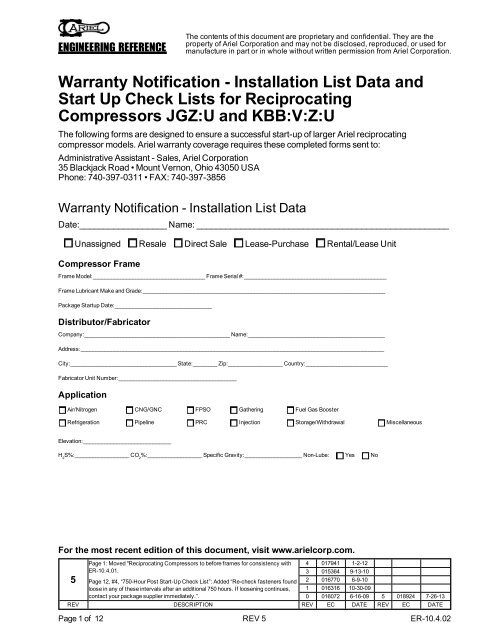
Warranty Notification - Installation List Data and<br />
Start Up Check Lists for Reciprocating<br />
Compressors JGZ:U and KBB:V:Z:U<br />
The following forms are designed to ensure a successful start-up of larger <strong>Ariel</strong> reciprocating<br />
compressor models. <strong>Ariel</strong> warranty coverage requires these completed forms sent to:<br />
Administrative Assistant - Sales, <strong>Ariel</strong> <strong>Corporation</strong><br />
35 Blackjack Road • Mount Vernon, Ohio 43050 USA<br />
Phone: 740-397-0311 • FAX: 740-397-3856<br />
Warranty Notification - Installation List Data<br />
Date:__________________ Name: ____________________________________________________<br />
Unassigned Resale Direct Sale Lease-Purchase Rental/Lease Unit<br />
Compressor Frame<br />
Frame Model:_____________________________________ Frame Serial #:_______________________________________________<br />
Frame Lubricant Make and Grade:________________________________________________________________________________<br />
Package Startup Date:________________________________<br />
Distributor/Fabricator<br />
Company:________________________________________________ Name:_____________________________________________<br />
Address:____________________________________________________________________________________________________<br />
City:___________________________________ State:________ Zip:__________________ Country:___________________________<br />
Fabricator Unit Number:_______________________________________<br />
Application<br />
Air/Nitrogen CNG/GNC FPSO Gathering Fuel Gas Booster<br />
Refrigeration Pipeline PRC Injection Storage/Withdrawal Miscellaneous<br />
Elevation:_____________________________<br />
H 2<br />
S%:__________________ CO 2<br />
%:__________________ Specific Gravity:___________________ Non-Lube: Yes No<br />
For the most recent edition of this document, visit www.arielcorp.com.<br />
5<br />
Page 1: Moved "Reciprocating Compressors to before frames for consistency with<br />
<strong>ER</strong>-10.4.01.<br />
Page 12, #4, “750-Hour Post Start-Up Check List”: Added “Re-check fasteners found<br />
loose in any of these intervals after an additional 750 hours. If loosening continues,<br />
contact your package supplier immediately.”.<br />
4 017941 1-2-12<br />
3 015364 9-13-10<br />
2 016770 6-9-10<br />
1 016316 10-30-09<br />
0 016072 6-16-09 5 018924 7-26-13<br />
REV DESCRIPTION REV EC DATE REV EC DATE<br />
Page 1 of 12 REV 5 <strong>ER</strong>-<strong>10.4.02</strong>
ENGINE<strong>ER</strong>ING REF<strong>ER</strong>ENCE<br />
The contents of this document are proprietary and confidential. They are the<br />
property of <strong>Ariel</strong> <strong>Corporation</strong> and may not be disclosed, reproduced, or used for<br />
manufacture in part or in whole without written permission from <strong>Ariel</strong> <strong>Corporation</strong>.<br />
Frame Serial #:_______________________________________________<br />
Unit Location<br />
Customer Name:______________________________________________________________________________________________<br />
Project/Lease Name: ___________________________________________________________________________________________<br />
Closest Town:________________________________ State:_________ Country:______________________ Offshore: Yes No<br />
Directions to Location or GPS:____________________________________________________________________________________<br />
___________________________________________________________________________________________________________<br />
___________________________________________________________________________________________________________<br />
___________________________________________________________________________________________________________<br />
Customer Contact Person:____________________________________________ Contact Phone:______________________________<br />
Contact Email:_______________________________________________________________________ OK to contact: Yes No<br />
Driver<br />
Driver Manufacturer:___________________________________________________ Driver Model:____________________________<br />
Driver Type:______________________________ Applied RPM:___________________ Name Plate HP (kW):____________________<br />
Coupling Manufacturer:_____________________________________________ Coupling Model:______________________________<br />
Compressor Cylinders and Operating Conditions<br />
Cylinder<br />
Class<br />
Stage<br />
Number<br />
Throw<br />
Number<br />
Serial<br />
Number<br />
Bore Dia.<br />
In. (mm)<br />
Inlet Temp.<br />
°F (°C)<br />
Inlet Pres.<br />
psig (barg)<br />
Disc. Temp<br />
°F (°C)<br />
Disc. Pres.<br />
psig (barg)<br />
_________ _________ _________ _________ _________ _________ _________ _________ _________<br />
_________ _________ _________ _________ _________ _________ _________ _________ _________<br />
_________ _________ _________ _________ _________ _________ _________ _________ _________<br />
_________ _________ _________ _________ _________ _________ _________ _________ _________<br />
_________ _________ _________ _________ _________ _________ _________ _________ _________<br />
_________ _________ _________ _________ _________ _________ _________ _________ _________<br />
Cylinder Lubricant Make and Grade:______________________________________________________________________________<br />
Documentation and Accessories<br />
Check all items included in the shipment:<br />
Maintenance and Repair Manual Yes No Recommended Spares List Yes No<br />
Start-Up Spare Parts Yes No Unit Start and Stop Procedures Yes No<br />
Toolbox w/<strong>Ariel</strong> Tools Yes No Toolbox with Hydraulic Tools (optional) Yes No<br />
Unit Parts List Yes No Toolbox with SAE Hand Tools (optional) Yes No<br />
Commissioning Agent<br />
Name:________________________________________________ Company:_____________________________________________<br />
Address:____________________________________________________________________________________________________<br />
City:___________________________________ State:________ Zip:__________________ Country:___________________________<br />
Phone:________________________________________________ Email:________________________________________________<br />
Page 2 of 12 REV 5 <strong>ER</strong>-<strong>10.4.02</strong>
ENGINE<strong>ER</strong>ING REF<strong>ER</strong>ENCE<br />
The contents of this document are proprietary and confidential. They are the<br />
property of <strong>Ariel</strong> <strong>Corporation</strong> and may not be disclosed, reproduced, or used for<br />
manufacture in part or in whole without written permission from <strong>Ariel</strong> <strong>Corporation</strong>.<br />
Frame Serial #:_______________________________________________<br />
START-UP CHECK LIST - ITEMS TO CHECK IN THE FIELD AT COMMISSIONING<br />
Description Date Checked Date Verified<br />
1. Confirm receipt of all <strong>Ariel</strong> supplied components and protection of<br />
all containers and parts against storage-related damage.<br />
2. Check and verify the top cover data plate of the compressor<br />
frame for compressor design limitations such as rod load, maximum<br />
and minimum speed, and maximum lube oil temperature.<br />
3. Check and verify the availability of correct start-up spares, hand<br />
tools, special tools, compressor parts list and drawings, and technical<br />
manuals at installation.<br />
4. Check and verify the <strong>Ariel</strong> lube sheet and Lubrication Specification<br />
matches the recommended oil grade and viscosity for<br />
the service.<br />
5. Check and verify all lube oil piping cleanliness per <strong>Ariel</strong> lubrication<br />
specifications (see <strong>ER</strong>-56.06).<br />
6. Verify lube oil storage and supply line cleanliness per <strong>ER</strong>-56.06).<br />
Verify crankcase oil supply isolation valve is open.<br />
7. Verify pre-lube piping cleanliness per <strong>ER</strong>-56.06) and correct circuit<br />
operation.<br />
8. Verify there is an oil cooler and high temperature shutdown for the<br />
oil into the compressor frame.<br />
9. Verify whether the temperature control valve installation is blending<br />
or diverting (blending preferred). ________________________<br />
10. Check compressor crankcase oil level controller for proper installation,<br />
operation, levelness, and venting.<br />
11. If applicable, check cooling water circuit cleanliness for the oil<br />
cooler and cooled packing per Maintenance and Repair Manual.<br />
Verify correct routing and test pump rotation. Set pressure appropriately<br />
per Maintenance and Repair Manual and leak test.<br />
12. Verify correct filter element installation. Prime the oil filter element<br />
and all lube oil piping with oil.<br />
13. Verify proper compressor crankcase oil level before starting<br />
(about 7/8 full in site glass).<br />
14. Verify correct installation of a low oil pressure shutdown tubed to<br />
the downstream side of the oil filter.<br />
15. Operate pre-lube system.<br />
16. Tighten frame hold down bolting (see <strong>ER</strong>-26).<br />
Customer:___________<br />
Commissioning Agent:<br />
__________________<br />
Commissioning Agent:<br />
__________________<br />
Commissioning Agent:<br />
__________________<br />
Commissioning Agent:<br />
__________________<br />
Commissioning Agent:<br />
__________________<br />
Commissioning Agent:<br />
__________________<br />
Commissioning Agent:<br />
__________________<br />
Commissioning Agent:<br />
__________________<br />
Commissioning Agent:<br />
__________________<br />
Commissioning Agent:<br />
__________________<br />
Commissioning Agent:<br />
__________________<br />
Commissioning Agent:<br />
__________________<br />
Commissioning Agent:<br />
__________________<br />
Commissioning Agent:<br />
__________________<br />
Commissioning Agent:<br />
__________________<br />
Commissioning Agent:<br />
__________________<br />
Distributor:<br />
__________________<br />
Distributor:<br />
__________________<br />
Distributor:<br />
__________________<br />
Distributor:<br />
__________________<br />
Distributor:<br />
__________________<br />
Distributor:<br />
__________________<br />
Distributor:<br />
__________________<br />
Distributor:<br />
__________________<br />
Distributor:<br />
__________________<br />
Distributor:<br />
__________________<br />
Distributor:<br />
__________________<br />
Distributor:<br />
__________________<br />
Distributor:<br />
__________________<br />
Distributor:<br />
__________________<br />
Distributor:<br />
__________________<br />
Distributor:<br />
__________________<br />
Page 3 of 12 REV 5 <strong>ER</strong>-<strong>10.4.02</strong>
ENGINE<strong>ER</strong>ING REF<strong>ER</strong>ENCE<br />
The contents of this document are proprietary and confidential. They are the<br />
property of <strong>Ariel</strong> <strong>Corporation</strong> and may not be disclosed, reproduced, or used for<br />
manufacture in part or in whole without written permission from <strong>Ariel</strong> <strong>Corporation</strong>.<br />
Frame Serial #:_______________________________________________<br />
START-UP CHECK LIST - ITEMS TO CHECK IN THE FIELD AT COMMISSIONING<br />
Description Date Checked Date Verified<br />
17. Record “out of plane” readings (pre-grout).<br />
_________ _________ _________ _________ _________ _________<br />
Drive End _________ _________ _________ _________ _________ _________ Auxiliary End<br />
NOTE: See <strong>ER</strong>-82.<br />
18. If applicable, check compressor frame mounting grout or chocks<br />
for proper installation to top of base frame. Also check for cracks.<br />
19. If applicable, check compressor skid-to-foundation grouting for<br />
proper installation, grout type, and internal support.<br />
Commissioning Agent:<br />
__________________<br />
Commissioning Agent:<br />
__________________<br />
Commissioning Agent:<br />
__________________<br />
Distributor:<br />
__________________<br />
Distributor:<br />
__________________<br />
Distributor:<br />
__________________<br />
20. Record soft foot readings. Over 0.002 inches (0.05 mm) pull-down on any frame foot requires correction.<br />
_________ _________ _________ _________ _________ _________<br />
Drive End _________ _________ _________ _________ _________ _________ Auxiliary End<br />
NOTE: See <strong>ER</strong>-82.<br />
21. If applicable, re-assemble the guide/cylinder components.<br />
22. Check and verify connecting rods can move freely without damage<br />
before rotating the crankshaft.<br />
NOTE: Pre-lube compressor before turning crankshaft.<br />
23. Check crosshead guide shimming for correct pre-load and hold<br />
down bolt torque.<br />
Commissioning Agent:<br />
__________________<br />
Commissioning Agent:<br />
__________________<br />
Commissioning Agent:<br />
__________________<br />
Commissioning Agent:<br />
__________________<br />
Distributor:<br />
__________________<br />
Distributor:<br />
__________________<br />
Distributor:<br />
__________________<br />
Distributor:<br />
__________________<br />
24. Record piston end clearances with feeler gages (see Maintenance and Repair Manual, Appendix B).<br />
Throw 1 2 3 4 5 6<br />
Head End _________ _________ _________ _________ _________ _________<br />
Crank End _________ _________ _________ _________ _________ _________<br />
NOTE: Pre-lube compressor before turning crankshaft.<br />
Commissioning Agent:<br />
__________________<br />
Distributor:<br />
__________________<br />
Page 4 of 12 REV 5 <strong>ER</strong>-<strong>10.4.02</strong>
ENGINE<strong>ER</strong>ING REF<strong>ER</strong>ENCE<br />
The contents of this document are proprietary and confidential. They are the<br />
property of <strong>Ariel</strong> <strong>Corporation</strong> and may not be disclosed, reproduced, or used for<br />
manufacture in part or in whole without written permission from <strong>Ariel</strong> <strong>Corporation</strong>.<br />
Frame Serial #:_______________________________________________<br />
START-UP CHECK LIST - ITEMS TO CHECK IN THE FIELD AT COMMISSIONING<br />
Description Date Checked Date Verified<br />
25. Record rod run out (see Maintenance and Repair Manual, Section 4 for maximum acceptable readings).<br />
Throw 1 2 3 4 5 6<br />
Piston @ CE<br />
Vertical:<br />
Mid-Stroke _________ _________ _________ _________ _________ _________<br />
Piston @ HE<br />
Piston @ CE<br />
_________ _________ _________ _________ _________ _________<br />
_________ _________ _________ _________ _________ _________<br />
Horizontal:<br />
Mid-Stroke _________ _________ _________ _________ _________ _________<br />
Piston @ HE<br />
_________ _________ _________ _________ _________ _________<br />
_________ _________ _________ _________ _________ _________<br />
NOTE: Pre-lube compressor before turning crankshaft.<br />
26. Measure crosshead clearances with cylinders mounted. To<br />
check top, insert 0.5 inch (12.7 mm) wide feelers from one side<br />
edge across to the opposite side, at both ends. See Maintenance<br />
and Repair Manual, Appendix B for limits. To check bottom,<br />
insert a 0.0015 inch (0.038 mm) feeler at the four corners; feeler<br />
should insert no more than 0.50 (13 mm). Record values:<br />
Throw Top Min. Top Max. Bottom Max. (Corners)<br />
1<br />
2<br />
3<br />
4<br />
5<br />
6<br />
_________<br />
_________<br />
_________<br />
_________<br />
_________<br />
_________<br />
_________<br />
_________<br />
_________<br />
_________<br />
_________<br />
_________<br />
27. Record “out of plane” readings (post-grout).<br />
_________<br />
_________<br />
_________<br />
_________<br />
_________<br />
_________<br />
Commissioning Agent:<br />
__________________<br />
Commissioning Agent:<br />
__________________<br />
Distributor:<br />
__________________<br />
Distributor:<br />
__________________<br />
_________ _________ _________ _________ _________ _________<br />
Drive End _________ _________ _________ _________ _________ _________ Auxiliary End<br />
NOTE: See <strong>Ariel</strong> <strong>ER</strong>-82. If applicable after reassembly, send<br />
readings to <strong>Ariel</strong>.<br />
28. For electric motor drivers, check and verify the motor shaft is set<br />
at its magnetic center before positioning axial clearance. With the<br />
coupling disconnected, check and verify driver rotation matches<br />
the compressor rotation arrow.<br />
29. Check coupling bolt torque to coupling manufacturer<br />
recommendations.<br />
Commissioning Agent:<br />
__________________<br />
Commissioning Agent:<br />
__________________<br />
Commissioning Agent:<br />
__________________<br />
Distributor:<br />
__________________<br />
Distributor:<br />
__________________<br />
Distributor:<br />
__________________<br />
Page 5 of 12 REV 5 <strong>ER</strong>-<strong>10.4.02</strong>
ENGINE<strong>ER</strong>ING REF<strong>ER</strong>ENCE<br />
The contents of this document are proprietary and confidential. They are the<br />
property of <strong>Ariel</strong> <strong>Corporation</strong> and may not be disclosed, reproduced, or used for<br />
manufacture in part or in whole without written permission from <strong>Ariel</strong> <strong>Corporation</strong>.<br />
Frame Serial #:_______________________________________________<br />
START-UP CHECK LIST - ITEMS TO CHECK IN THE FIELD AT COMMISSIONING<br />
Description Date Checked Date Verified<br />
30. Check and verify compressor to driver alignment (installed on<br />
site, cold). Record dial indicator readings in inches (mm) at the 3,<br />
6, 9 and 12 o’clock positions or attach alignment tool print-out.<br />
Commissioning Agent:<br />
__________________<br />
Distributor:<br />
__________________<br />
If using a laser alignment tool, make a print out and attach it to this<br />
document.<br />
31. Check and verify compressor crankshaft thrust clearance. The<br />
shaft should remain stationary after thrusting each direction (see<br />
Maintenance and Repair Manual, Appendix B).<br />
__________________________ __________________________<br />
Commissioning Agent:<br />
__________________<br />
Distributor:<br />
__________________<br />
START-UP CHECK LIST - PROCESS PIPING VENTS AND DRAINS<br />
Description Date Checked Date Verified<br />
1. Verify the bottle and process pipe installation contains no bolt<br />
bound flanges or elevation differences that may stress the compressor<br />
cylinders<br />
2. Verify cold adjustment of any bottle or cylinder supports.<br />
3. Verify correct inlet screen orientation in process piping.<br />
4. Check, verify, & record process piping orifice sizes & locations.<br />
_______________________________________________________<br />
_______________________________________________________<br />
_______________________________________________________<br />
_______________________________________________________<br />
5. Check and verify piping and instrumentation diagrams are "as<br />
built". Check all valves for correct position and easy operation<br />
and verify correct installation of all identification tag numbers. Verify<br />
tag numbers match component numbers on the drawing.<br />
6. Check and verify routing and diameters of tubing for all vents,<br />
drains, and instrument air (diameters must equal the full diameter<br />
of ports). Check and verify bracketing is according to industry<br />
standard and good engineering practices.<br />
Commissioning Agent:<br />
__________________<br />
Commissioning Agent:<br />
__________________<br />
Commissioning Agent:<br />
__________________<br />
Commissioning Agent:<br />
__________________<br />
Commissioning Agent:<br />
__________________<br />
Commissioning Agent:<br />
__________________<br />
Distributor:<br />
__________________<br />
Distributor:<br />
__________________<br />
Distributor:<br />
__________________<br />
Distributor:<br />
__________________<br />
Distributor:<br />
__________________<br />
Distributor:<br />
__________________<br />
Page 6 of 12 REV 5 <strong>ER</strong>-<strong>10.4.02</strong>
ENGINE<strong>ER</strong>ING REF<strong>ER</strong>ENCE<br />
The contents of this document are proprietary and confidential. They are the<br />
property of <strong>Ariel</strong> <strong>Corporation</strong> and may not be disclosed, reproduced, or used for<br />
manufacture in part or in whole without written permission from <strong>Ariel</strong> <strong>Corporation</strong>.<br />
Frame Serial #:_______________________________________________<br />
START-UP CHECK LIST - PROCESS PIPING VENTS AND DRAINS<br />
Description Date Checked Date Verified<br />
7. Check and verify vents and drains of the primary and secondary<br />
packing-case and the crosshead distance piece are open and<br />
tubed to a safe atmosphere.<br />
8. Check and verify safety relief valve installation to protect cylinders,<br />
piping, and cooler for each compression stage.<br />
9. Record method of suction pressure control and valve size.<br />
_________________________ _________________________<br />
10. Check, verify, and record line size, valve type, and diameter of<br />
the by-pass line.<br />
_______________________________________________________<br />
_______________________________________________________<br />
_______________________________________________________<br />
11. Check and verify crankcase breather element is open to atmosphere<br />
and clean.<br />
12. Check and verify torque to spec on all gas containment and other<br />
fasteners where loosening may result in a safety hazard or equipment<br />
failure including: gas nozzle flanges, valve caps, cylinder<br />
heads, compressor rod packing, and crosshead guide support.<br />
See <strong>ER</strong>-63.<br />
13. Perform leak testing on installed piping and vessels.<br />
14. Record “out of plane” readings (final, after bottle guide shimming).<br />
Commissioning Agent:<br />
__________________<br />
Commissioning Agent:<br />
__________________<br />
Commissioning Agent:<br />
__________________<br />
Commissioning Agent:<br />
__________________<br />
Commissioning Agent:<br />
__________________<br />
Commissioning Agent:<br />
__________________<br />
Commissioning Agent:<br />
__________________<br />
Distributor:<br />
__________________<br />
Distributor:<br />
__________________<br />
Distributor:<br />
__________________<br />
Distributor:<br />
__________________<br />
Distributor:<br />
__________________<br />
Distributor:<br />
__________________<br />
Distributor:<br />
__________________<br />
_________ _________ _________ _________ _________ _________<br />
Drive End _________ _________ _________ _________ _________ _________ Auxiliary End<br />
NOTE: See <strong>ER</strong>-82.<br />
Commissioning Agent:<br />
__________________<br />
Distributor:<br />
__________________<br />
START-UP CHECK LIST - INSTRUMENTATION<br />
Description Date Checked Date Verified<br />
1. Check and verify correct installation of all required instrumentation<br />
and that devices meet applicable codes.<br />
2. Check and verify proper grounding of compressor skid to a suitable<br />
earth ground.<br />
3. Before starting, verify the programmable logic controller (PLC)<br />
operates the complete compressor package correctly. <strong>Ariel</strong><br />
reviewed and approved the full start sequence. NOTE: Send<br />
<strong>Ariel</strong> a copy of the load steps.<br />
Commissioning Agent:<br />
__________________<br />
Commissioning Agent:<br />
__________________<br />
Commissioning Agent:<br />
__________________<br />
Distributor:<br />
__________________<br />
Distributor:<br />
__________________<br />
Distributor:<br />
__________________<br />
Page 7 of 12 REV 5 <strong>ER</strong>-<strong>10.4.02</strong>
ENGINE<strong>ER</strong>ING REF<strong>ER</strong>ENCE<br />
The contents of this document are proprietary and confidential. They are the<br />
property of <strong>Ariel</strong> <strong>Corporation</strong> and may not be disclosed, reproduced, or used for<br />
manufacture in part or in whole without written permission from <strong>Ariel</strong> <strong>Corporation</strong>.<br />
Frame Serial #:_______________________________________________<br />
START-UP CHECK LIST - INSTRUMENTATION<br />
Description Date Checked Date Verified<br />
4. Check and verify operation of required shutdowns. See <strong>ER</strong>-<br />
56.07.<br />
5. Check and verify the set point for the high compressor oil temperature<br />
shutdown at 190°F (88°C) maximum.<br />
6. Check and verify proper vibration shutdown installation and operation.<br />
Record alarm and shut down settings.<br />
_______________________________________________________<br />
_______________________________________________________<br />
_______________________________________________________<br />
_______________________________________________________<br />
7. Verify operation of suction, inter-stage, and discharge pressure<br />
shutdowns. Record alarm and shutdown settings.<br />
_______________________________________________________<br />
_______________________________________________________<br />
_______________________________________________________<br />
_______________________________________________________<br />
8. Verify gas discharge temperature shutdowns operation. Record<br />
alarm and shutdown settings.<br />
_______________________________________________________<br />
_______________________________________________________<br />
_______________________________________________________<br />
_______________________________________________________<br />
9. Check and verify main bearing temperature shutdowns operation.<br />
10. Check and verify instrument air supply for adequate pressure and<br />
gas back pressure protection.<br />
11. Check and verify correct PLC operation of any solenoids.<br />
12. If applicable, check and verify flow meters, valves, and gauge<br />
positions for water-cooled packing.<br />
13. Check, verify, and record the over speed setting: _____________<br />
Commissioning Agent:<br />
__________________<br />
Commissioning Agent:<br />
__________________<br />
Commissioning Agent:<br />
__________________<br />
Commissioning Agent:<br />
__________________<br />
Commissioning Agent:<br />
__________________<br />
Commissioning Agent:<br />
__________________<br />
Commissioning Agent:<br />
__________________<br />
Commissioning Agent:<br />
__________________<br />
Commissioning Agent:<br />
__________________<br />
Commissioning Agent:<br />
__________________<br />
Distributor:<br />
__________________<br />
Distributor:<br />
__________________<br />
Distributor:<br />
__________________<br />
Distributor:<br />
__________________<br />
Distributor:<br />
__________________<br />
Distributor:<br />
__________________<br />
Distributor:<br />
__________________<br />
Distributor:<br />
__________________<br />
Distributor:<br />
__________________<br />
Distributor:<br />
__________________<br />
Page 8 of 12 REV 5 <strong>ER</strong>-<strong>10.4.02</strong>
ENGINE<strong>ER</strong>ING REF<strong>ER</strong>ENCE<br />
The contents of this document are proprietary and confidential. They are the<br />
property of <strong>Ariel</strong> <strong>Corporation</strong> and may not be disclosed, reproduced, or used for<br />
manufacture in part or in whole without written permission from <strong>Ariel</strong> <strong>Corporation</strong>.<br />
Frame Serial #:_______________________________________________<br />
START-UP CHECK LIST - FORCE FEED LUBRICATION SYSTEM<br />
Description Date Checked Date Verified<br />
1. Check and verify divider valve outlet ports against <strong>Ariel</strong> lube<br />
sheet to confirm correct routing of lines.<br />
2. Check and verify force feed lubricator box for proper oil level.<br />
3. Prime the force feed lubrication system through the purge port at<br />
the force feed pump discharge manifold. Check and verify each<br />
tube connection for tightness.<br />
4. For independent oil supply, verify a separate lubricator tank overflow<br />
exists.<br />
5. Check and verify operation of force feed lubrication system no<br />
flow shutdowns.<br />
6. Record color of force feed blow out discs (see Customer Technical<br />
Bulletin CTB-137 for disc ratings): ____________________<br />
7. Check, verify, and record recommended lube feed rates from lubricator<br />
data plate or “Parts Book” Cylinder Lubrication sheet.<br />
_______________________________________________________<br />
Commissioning Agent:<br />
__________________<br />
Commissioning Agent:<br />
__________________<br />
Commissioning Agent:<br />
__________________<br />
Commissioning Agent:<br />
__________________<br />
Commissioning Agent:<br />
__________________<br />
Commissioning Agent:<br />
__________________<br />
Commissioning Agent:<br />
__________________<br />
Distributor:<br />
__________________<br />
Distributor:<br />
__________________<br />
Distributor:<br />
__________________<br />
Distributor:<br />
__________________<br />
Distributor:<br />
__________________<br />
Distributor:<br />
__________________<br />
Distributor:<br />
__________________<br />
FINAL PRE-START CHECK LIST<br />
Description Date Checked Date Verified<br />
1. Operate pre-lube system. Record pre-lube pressure:__________<br />
2. For engine driven units, disable ignition and roll the engine with<br />
the starter to check and verify the compressor rolls freely. Check<br />
and verify oil pressure increases noticeably while rolling on the<br />
starter.<br />
3. For electric motors, bar the compressor over manually to check<br />
and verify it rolls freely.<br />
4. For machines compressing a combustible gas, purge the entire<br />
system including the piping, by-pass, recycle line, and compressor<br />
cylinders of all air.<br />
5. Check and verify correct position and operation of all valves.<br />
Check and verify operation of all compressor interfaces with the<br />
system.<br />
6. Review start-up instructions for all other package components.<br />
7. Complete the required review of the Start-Up and Operating<br />
Instructions for the unit with the unit operator.<br />
8. Ensure compressor PLC logic is understood and approved.<br />
Commissioning Agent:<br />
__________________<br />
Commissioning Agent:<br />
__________________<br />
Commissioning Agent:<br />
__________________<br />
Commissioning Agent:<br />
__________________<br />
Commissioning Agent:<br />
__________________<br />
Commissioning Agent:<br />
__________________<br />
Commissioning Agent:<br />
__________________<br />
Commissioning Agent:<br />
__________________<br />
Distributor:<br />
__________________<br />
Distributor:<br />
__________________<br />
Distributor:<br />
__________________<br />
Distributor:<br />
__________________<br />
Distributor:<br />
__________________<br />
Distributor:<br />
__________________<br />
Distributor:<br />
__________________<br />
Distributor:<br />
__________________<br />
Page 9 of 12 REV 5 <strong>ER</strong>-<strong>10.4.02</strong>
ENGINE<strong>ER</strong>ING REF<strong>ER</strong>ENCE<br />
The contents of this document are proprietary and confidential. They are the<br />
property of <strong>Ariel</strong> <strong>Corporation</strong> and may not be disclosed, reproduced, or used for<br />
manufacture in part or in whole without written permission from <strong>Ariel</strong> <strong>Corporation</strong>.<br />
Frame Serial #:_______________________________________________<br />
INITIAL POST START-UP CHECK LIST<br />
Description Date Checked Date Verified<br />
1. Check and verify immediate oil pressure increase. Enable oil pressure<br />
shutdown and bearing temperature shutdowns. Record initial<br />
pressure at operating speed.___________________________<br />
2. Check and verify oil filter pressure gauges. Record initial differential:<br />
_____________________________________________<br />
3. Check and verify the low oil pressure shutdown is active and set<br />
at 45 psig (3.1 barg).<br />
4. Check and verify lube oil pressure set at 50 to 60 psig (3.5 to 4.2<br />
barg) at operating speed and temperature (see Maintenance and<br />
Repair Manual, Section 4). Record final setting:______________<br />
5. Record oil filter maximum differential reference value listed on the<br />
compressor top cover filter data plate: ______________________<br />
6. Listen and feel for any strange noises or vibration in the compressor<br />
or piping. Record any occurrences.<br />
_______________________________________________________<br />
_______________________________________________________<br />
_______________________________________________________<br />
_______________________________________________________<br />
7. Check and verify high discharge gas temperature shutdowns are<br />
set about 10% above normal operating temperature (350 °F (177<br />
°C) maximum) and functioning.<br />
8. Check and verify gas pressure shutdowns are set as close as<br />
possible and establish them to protect the unit from over rod load<br />
and crosshead pin non-reversal.<br />
9. Check and verify distribution block cycle time indicator and set<br />
lubricator pump for proper break-in rate.<br />
10. For electric motor driven units, check and verify the magnetic<br />
center position. Check and verify the coupling does not "hunt" during<br />
normal operation.<br />
11. Check and verify the unit and piping is free from any gas or fluid<br />
leaks. Record any occurrences.<br />
_______________________________________________________<br />
_______________________________________________________<br />
_______________________________________________________<br />
_______________________________________________________<br />
12. Check and verify scrubber high level shutdowns operation and<br />
check scrubber dumps operation and frequency.<br />
13. Check, verify, and record tank levels that indicate the amount of<br />
liquids removed from the gas. ____________________________<br />
Commissioning Agent:<br />
__________________<br />
Commissioning Agent:<br />
__________________<br />
Commissioning Agent:<br />
__________________<br />
Commissioning Agent:<br />
__________________<br />
Commissioning Agent:<br />
__________________<br />
Commissioning Agent:<br />
__________________<br />
Commissioning Agent:<br />
__________________<br />
Commissioning Agent:<br />
__________________<br />
Commissioning Agent:<br />
__________________<br />
Commissioning Agent:<br />
__________________<br />
Commissioning Agent:<br />
__________________<br />
Commissioning Agent:<br />
__________________<br />
Commissioning Agent:<br />
__________________<br />
Distributor:<br />
__________________<br />
Distributor:<br />
__________________<br />
Distributor:<br />
__________________<br />
Distributor:<br />
__________________<br />
Distributor:<br />
__________________<br />
Distributor:<br />
__________________<br />
Distributor:<br />
__________________<br />
Distributor:<br />
__________________<br />
Distributor:<br />
__________________<br />
Distributor:<br />
__________________<br />
Distributor:<br />
__________________<br />
Distributor:<br />
__________________<br />
Distributor:<br />
__________________<br />
Page 10 of 12 REV 5 <strong>ER</strong>-<strong>10.4.02</strong>
ENGINE<strong>ER</strong>ING REF<strong>ER</strong>ENCE<br />
The contents of this document are proprietary and confidential. They are the<br />
property of <strong>Ariel</strong> <strong>Corporation</strong> and may not be disclosed, reproduced, or used for<br />
manufacture in part or in whole without written permission from <strong>Ariel</strong> <strong>Corporation</strong>.<br />
Frame Serial #:_______________________________________________<br />
INITIAL POST START-UP CHECK LIST<br />
Description Date Checked Date Verified<br />
14. Check and verify piston rod packings seal properly in the primary<br />
packing vents.<br />
15. Check and verify operation of all safety functions to ensure unit<br />
shutdown upon indication.<br />
16. If applicable, check and verify main bearing temperatures and record.<br />
Watch for even bearing temperature increase.<br />
17. During various operational conditions, use the <strong>Ariel</strong> performance<br />
program to check and verify operational characteristics of various<br />
load steps.<br />
18. If applicable, check and verify torsional analysis with on-site monitoring.<br />
Commissioning Agent:<br />
__________________<br />
Commissioning Agent:<br />
__________________<br />
Commissioning Agent:<br />
__________________<br />
Commissioning Agent:<br />
__________________<br />
Commissioning Agent:<br />
__________________<br />
Distributor:<br />
__________________<br />
Distributor:<br />
__________________<br />
Distributor:<br />
__________________<br />
Distributor:<br />
__________________<br />
Distributor:<br />
__________________<br />
24-HOUR POST START-UP CHECK LIST<br />
Description Date Checked Date Verified<br />
1. Record "hot" alignment readings after reaching normal operating<br />
temperatures and components become heat soaked. Shutdown<br />
and vent gas system. Within 30 minutes and while components<br />
are still hot, record dial indicator readings in inches (mm) at the 3,<br />
6, 9 and 12 o’clock positions on lines provided below:<br />
Commissioning Agent:<br />
__________________<br />
Distributor:<br />
__________________<br />
If using a laser alignment tool, make a print out and attach it to<br />
this document.<br />
2. If using a discharge bottle or head end cylinder supports, adjust<br />
when components are heat soaked to ensure no excessive<br />
forces exist to cause detrimental cylinder deflection.<br />
3. Check and verify torque on gas nozzle flange, valve cap, cylinder<br />
head, compressor rod packing flange, and guide to frame bolting.<br />
4. Complete <strong>Ariel</strong>’s “Compressor Warranty Notification - Installation<br />
List Data” (see pages 1 to 2).<br />
Commissioning Agent:<br />
__________________<br />
Commissioning Agent:<br />
__________________<br />
Commissioning Agent:<br />
__________________<br />
Distributor:<br />
__________________<br />
Distributor:<br />
__________________<br />
Distributor:<br />
__________________<br />
Page 11 of 12 REV 5 <strong>ER</strong>-<strong>10.4.02</strong>
ENGINE<strong>ER</strong>ING REF<strong>ER</strong>ENCE<br />
The contents of this document are proprietary and confidential. They are the<br />
property of <strong>Ariel</strong> <strong>Corporation</strong> and may not be disclosed, reproduced, or used for<br />
manufacture in part or in whole without written permission from <strong>Ariel</strong> <strong>Corporation</strong>.<br />
Frame Serial #:_______________________________________________<br />
750-HOUR POST START-UP CHECK LIST<br />
Description Date Checked Date Verified<br />
1. Check and verify the equipment performance design point. If site<br />
conditions prevent design point achievement, use a mutually<br />
agreed on secondary point.<br />
2. Perform a vibration and pulsation survey to validate system<br />
design and rectify any issues.<br />
3. Address all package issues, discrepancies, or deficiencies.<br />
4. Check and verify torque on gas nozzle flange, valve cap, cylinder<br />
head, and compressor rod packing flange bolting. Re-check fasteners<br />
found loose in any of these intervals after an additional 750<br />
hours. If loosening continues, contact your package supplier<br />
immediately.<br />
5. Send completed form and check lists (pages 1 to 12) to <strong>Ariel</strong> as<br />
noted on page 1.<br />
Commissioning Agent:<br />
__________________<br />
Commissioning Agent:<br />
__________________<br />
Commissioning Agent:<br />
__________________<br />
Commissioning Agent:<br />
__________________<br />
Commissioning Agent:<br />
__________________<br />
Distributor:<br />
__________________<br />
Distributor:<br />
__________________<br />
Distributor:<br />
__________________<br />
Distributor:<br />
__________________<br />
Distributor:<br />
__________________<br />
Page 12 of 12 REV 5 <strong>ER</strong>-<strong>10.4.02</strong>


