Compression Fitting Assembly Procedure - Franklin Fueling Systems
Compression Fitting Assembly Procedure - Franklin Fueling Systems
Compression Fitting Assembly Procedure - Franklin Fueling Systems

Create successful ePaper yourself
Turn your PDF publications into a flip-book with our unique Google optimized e-Paper software.
<strong>Compression</strong> <strong>Fitting</strong> <strong>Assembly</strong> <strong>Procedure</strong><br />
On occasion it is necessary to use compression fittings<br />
to extend or terminate UPP pipe work. This can be<br />
achieved using the following assembly procedures.<br />
Note: <strong>Compression</strong> fittings must only be used inside<br />
containment, i.e. Sumps and Chambers, and<br />
NOT direct-buried or used in contact with soil.<br />
General Rules for All <strong>Fitting</strong>s<br />
1. Pipe ends must be cut square and smooth, i.e.<br />
Perpendicular to axis.<br />
2. Cut pipe to length allowing for correct insertion<br />
depth into fitting.<br />
3. Chamfer pipe bore.<br />
4. Remove all burrs and swarf from pipe.<br />
11-50x / 63x Series models<br />
Model<br />
Description<br />
11-501M BSPT Termination, 50 mm /1.5" BSPT<br />
11-503F BSPT 90º 50 mm/1.5" BSPT Female<br />
11-508F BSPT TEE 1.5" BSPT Female<br />
11-50X OL Olive (<strong>Compression</strong> Ring) for 11-50X<br />
11-631M BSPT Termination, 63 MM 2" BSPT<br />
11-631M-1 BSPT Termination, 63 MM 1.5" BSPT<br />
11-63X OL Olive (<strong>Compression</strong> Ring) for 11-63X<br />
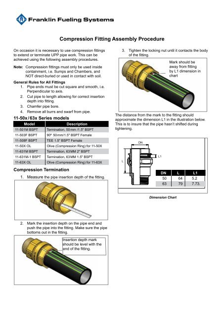
<strong>Compression</strong> Termination<br />
1. Measure the pipe insertion depth of the fitting.<br />
3. Tighten the locking nut until it contacts the body<br />
of the fitting.<br />
Mark should be<br />
away from fitting<br />
by L1 dimension in<br />
chart<br />
The distance from the mark to the fitting should<br />
approximate the dimension L1 in the illustration below.<br />
This is to insure that the pipe hasn’t shifted during<br />
tightening.<br />
L<br />
DN<br />
L1<br />
DN L L1<br />
50 64 5.2<br />
63 79 7.73.<br />
Dimension Chart<br />
2. Mark the insertion depth on the pipe end and<br />
push the pipe into the fitting. Make sure the pipe<br />
bottoms out in the fitting.<br />
Insertion depth mark<br />
should be level with the<br />
end of the fitting.
<strong>Compression</strong> Terminations (11.321)<br />
1. Fully insert support collar into pipe end.<br />
<strong>Compression</strong> Terminations (11-032-EC)<br />
1. Cut the pipe square, allowing for correct<br />
insertion depth into fitting and remove all burs.<br />
2. Seal is supplied pre-greased.<br />
2. Disassemble fitting and slide locking nut and<br />
sealing ring on to the pipe.<br />
3. Mark the insertion depth on the pipe.<br />
3. Fully insert pipe into fitting.<br />
4. Push the pipe into the fitting through the clamp<br />
ring until the first stop, meaning you have<br />
reached the seal. Push the pipe through the<br />
seal until you reach the pipe stop of the fitting.<br />
Check the mark of the insert depth of the pipe<br />
for correct assembly.<br />
4. Tighten locking nut hand tight then wrench<br />
tighten a further two and a half turns.<br />
5. Tighten the nut hand tight plus one turn.
<strong>Compression</strong> <strong>Fitting</strong>s<br />
1. Cut the pipe square, allowing for correct insertion depth into fitting.<br />
2. Chamfer the tubing and remove all burrs, paying particular attention to the bore of the pipe.<br />
3. Remove the outer sleeve.<br />
4. Insert the bolt head between the clamp bosses.<br />
3<br />
4<br />
5. Mount the outer sleeve onto the pipe.<br />
6. Lubricate the O-ring and insert coupling into pipe.<br />
5<br />
7. Slide the outer sleeve up to rear face of the coupling.<br />
8. Lubricate the bolt / nut and faces of the clamp bosses.<br />
9. Tighten the fitting until the clamp bosses meet.<br />
6<br />
7<br />
8
© 2011 FFS 408001015 rev 1<br />
<strong>Franklin</strong> <strong>Fueling</strong> <strong>Systems</strong> LTD<br />
8 Olympus Close • Whitehouse Industrial Estate<br />
Ipswich, Suffolk IP1 5LN • United Kingdom<br />
Tel: +44 1473 243300 • Fax: +44 1473 243301