R-GAGE™ QT50R Retroreflective Sensor - Banner Engineering
R-GAGE™ QT50R Retroreflective Sensor - Banner Engineering
R-GAGE™ QT50R Retroreflective Sensor - Banner Engineering

You also want an ePaper? Increase the reach of your titles
YUMPU automatically turns print PDFs into web optimized ePapers that Google loves.
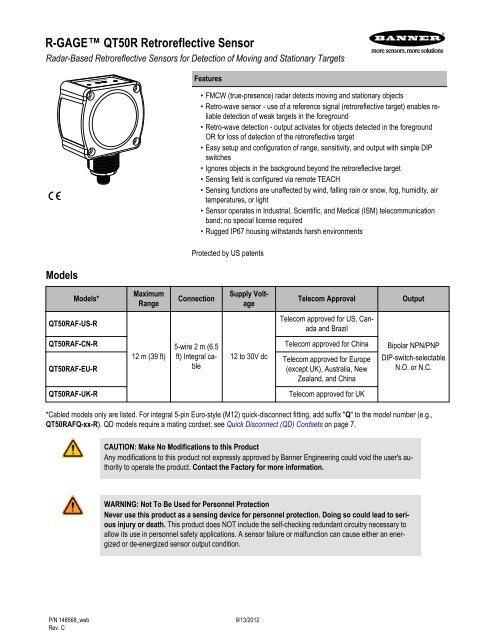
R-GAGE <strong>QT50R</strong> <strong>Retroreflective</strong> <strong>Sensor</strong><br />
Radar-Based <strong>Retroreflective</strong> <strong>Sensor</strong>s for Detection of Moving and Stationary Targets<br />
Models<br />
Models*<br />
<strong>QT50R</strong>AF-US-R<br />
Maximum<br />
Range<br />
12 m (39 ft)<br />
Features<br />
• FMCW (true-presence) radar detects moving and stationary objects<br />
• Retro-wave sensor - use of a reference signal (retroreflective target) enables reliable<br />
detection of weak targets in the foreground<br />
• Retro-wave detection - output activates for objects detected in the foreground<br />
OR for loss of detection of the retroreflective target<br />
• Easy setup and configuration of range, sensitivity, and output with simple DIP<br />
switches<br />
• Ignores objects in the background beyond the retroreflective target<br />
• Sensing field is configured via remote TEACH<br />
• Sensing functions are unaffected by wind, falling rain or snow, fog, humidity, air<br />
temperatures, or light<br />
• <strong>Sensor</strong> operates in Industrial, Scientific, and Medical (ISM) telecommunication<br />
band; no special license required<br />
• Rugged IP67 housing withstands harsh environments<br />
Protected by US patents<br />
Connection<br />
5-wire 2 m (6.5<br />
ft) Integral cable<br />
Supply Voltage<br />
12 to 30V dc<br />
Telecom Approval Output<br />
Telecom approved for US, Canada<br />
and Brazil<br />
<strong>QT50R</strong>AF-CN-R Telecom approved for China<br />
<strong>QT50R</strong>AF-EU-R<br />
Telecom approved for Europe<br />
(except UK), Australia, New<br />
Zealand, and China<br />
<strong>QT50R</strong>AF-UK-R Telecom approved for UK<br />
Bipolar NPN/PNP<br />
DIP-switch-selectable<br />
N.O. or N.C.<br />
*Cabled models only are listed. For integral 5-pin Euro-style (M12) quick-disconnect fitting, add suffix "Q" to the model number (e.g.,<br />
<strong>QT50R</strong>AFQ-xx-R). QD models require a mating cordset; see Quick Disconnect (QD) Cordsets on page 7.<br />
P/N 148568_web<br />
Rev. C<br />
CAUTION: Make No Modifications to this Product<br />
Any modifications to this product not expressly approved by <strong>Banner</strong> <strong>Engineering</strong> could void the user's authority<br />
to operate the product. Contact the Factory for more information.<br />
WARNING: Not To Be Used for Personnel Protection<br />
Never use this product as a sensing device for personnel protection. Doing so could lead to serious<br />
injury or death. This product does NOT include the self-checking redundant circuitry necessary to<br />
allow its use in personnel safety applications. A sensor failure or malfunction can cause either an energized<br />
or de-energized sensor output condition.<br />
9/13/2012
Overview<br />
The R-GAGE sensor emits a well-defined beam of high-frequency radio waves from an internal antenna. This emitted energy reflects off<br />
of a retroreflective target and returns to the receiving antenna. As long as the antenna is receiving reflected radio waves, the output will<br />
remain off. If an object blocks radio waves, the output will turn on. The distance range for the retroreflective target can be configured via<br />
remote TEACH wire. Objects beyond the retroreflective target are ignored (also called background suppression). In Normally Closed<br />
mode, the output operates like a foreground suppression sensor.<br />
<strong>Sensor</strong><br />
Output<br />
OFF<br />
<strong>Sensor</strong><br />
Output<br />
ON<br />
Figure 1. R-Gage Features<br />
Near<br />
Range<br />
1. Power LED: Green (power ON)<br />
2. Signal Strength LED: Red (flashes in proportion to signal<br />
strength)<br />
3. Output LEDs: Yellow (output energized); Red (configuration)<br />
Access DIP switches behind threaded cap on sensor back (not<br />
shown)<br />
Detects objects between sensor and reference target.<br />
Detects loss or obstruction of reference target.<br />
Any object in this area will switch the output,<br />
whether or not the object returns a good signal to the sensor.<br />
Position<br />
-0.4 m<br />
Taught Reference<br />
(e.g., wall or floor)<br />
Output ON Output OFF<br />
Sensing Distance<br />
Hysteresis<br />
-0.6 m<br />
Position<br />
+0.4 m<br />
Background<br />
Suppression<br />
Output ON<br />
Figure 2. <strong>Sensor</strong> detects radio waves reflected from corner cube reflector or background. Any object blocking the signal results<br />
in an output change<br />
<strong>Sensor</strong> Configuration<br />
The sensitivity, and output configuration can be selected via the DIP switches on the back of the sensor. The sensing distance must be<br />
configured via remote TEACH wire.<br />
Use the included spanner to open the screw-off cover on the back of the sensor and access the DIP switches.<br />
R-GAGE <strong>QT50R</strong> <strong>Retroreflective</strong> <strong>Sensor</strong><br />
Important: Tighten the DIP switch cover a full quarter turn after contact to maintain the watertight seal.<br />
2 www.bannerengineering.com - tel: 763-544-3164 P/N 148568_web<br />
Rev. C
R-GAGE <strong>QT50R</strong> <strong>Retroreflective</strong> <strong>Sensor</strong><br />
DIP Switch Functions<br />
Switch Function<br />
1, 2, 3 Not used<br />
4, 5, 6 Sensitivity (contrast between retroreflective target and foreground targets)<br />
7 Normally open/normally closed output functionality<br />
8 Response Speed<br />
DIP switch 1 is on the left and DIP switch 8 is on the right.<br />
Sensitivity Selection<br />
* Default settings<br />
Switch 4 Switch 5 Switch 6 Sensitivity Contrast<br />
0 0 0 8 Use for weak retro with strong targets<br />
0 0 1 7<br />
0 1 0 6<br />
0 * 1* 1* 5* Use for normal retro with normal targets<br />
1 0 0 4<br />
1 0 1 3<br />
1 1 0 2<br />
1 1 1 1 Use for strong retro with weak targets<br />
Output Configuration<br />
* Default settings<br />
Response Speed<br />
* Default settings<br />
Switch 7 Normally Open/Normally Closed<br />
0* N.O.<br />
1 N.C.<br />
Switch 8 ON OFF ON/OFF<br />
0 32 ms 68 ms 100 ms<br />
1* 258 ms 998 ms 1256 ms<br />
Installation<br />
For optimal performance, the sensor should be aimed perpendicular to the surface of the retroreflective target. Angling the sensor greater<br />
than 15 degrees with respect to a flat surface is not recommended.<br />
The retroreflective target must be the strongest target in the field of view. If another equally strong background target is in the field of<br />
view, the sensor may be taught the wrong target, or the sensing state may oscillate.<br />
After installing, a remote TEACH must be performed to teach the sensor the retroreflective target. The sensor will not operate correctly<br />
until a TEACH is performed. A TEACH must be performed each time the sensor is moved or the retroreflective target changes.<br />
P/N 148568_web<br />
Rev. C<br />
www.bannerengineering.com - tel: 763-544-3164 3
Remote Line TEACH<br />
The adjustable field, retroreflective target, and background suppression distances are set using a remote wire. For remote programming,<br />
connect a switch or digital input to the gray wire (remote line); length of the individual pulses is equal to the value T: 0.064 seconds < T <<br />
0.8 seconds<br />
Access Remote Line Teach<br />
Teach Distance<br />
Return to Run Mode<br />
Specifications<br />
Step Procedure Result<br />
• Double-pulse the remote line<br />
• Single-pulse the remote wire<br />
If the TEACH is successful, the sensor will be in a nonsensing<br />
state (output LEDs OFF)<br />
Output LEDs ON Red<br />
Output 1 LED flashes Red 10x<br />
Output LEDs OFF<br />
NOTE: A successful TEACH can be verified by placing an object in between the sensor and the retroreflective<br />
target after the TEACH has been performed. This should cause both Output LEDs to turn ON.<br />
Range<br />
The sensor is able to detect a proper retroreflective target<br />
(see Detectable Objects) up to 12 m (39.4 ft), depending<br />
on target<br />
Detectable Objects<br />
Objects containing metal, water, or similar high-dielectric<br />
materials<br />
Operating Principle<br />
Frequency modulated continuous-wave (FMCW) radar<br />
Operating Frequency<br />
24.00 to 24.25 GHz, ISM Band (varies slightly with<br />
model, depending on national telecom regulations)<br />
Supply Voltage<br />
12 to 30V dc, less than 100 mA, exclusive of load<br />
Supply Protection Circuitry<br />
Protected against reverse polarity and transient overvoltages<br />
Delay at Power-up<br />
Less than 2 seconds<br />
Output Configuration<br />
Bipolar NPN/PNP output, 150mA; DIP switch 7 selects<br />
N.O. (default) or N.C. operation<br />
Output Protection<br />
Protected against short circuit conditions<br />
Response Time<br />
DIP-Switch 8 selects ON/OFF response time<br />
R-GAGE <strong>QT50R</strong> <strong>Retroreflective</strong> <strong>Sensor</strong><br />
Indicators<br />
Power LED: Green (power ON)<br />
Signal Strength LED: Red, flashes in proportion to<br />
signal strength. Steady on at 4x excess gain. Only indicates<br />
signal amplitude, not target distance.<br />
Output LEDs: Yellow (output energized) / Red (configuration)<br />
See Figure 1. R-Gage Features on page 2<br />
Adjustments<br />
DIP-switch-configurable sensitivity, response time, and<br />
output configuration; remote line teach of the retroreflective<br />
target<br />
Construction<br />
Housing: ABS/polycarbonate<br />
Lightpipes: Acrylic<br />
Access Cap: Polyester<br />
Operating Temperature<br />
– 40° to + 65° C (– 40° to + 149° F)<br />
Environmental Rating<br />
IP67<br />
Connections<br />
Integral 5-wire 2 m (6.5 ft) cable or M12 Euro-style QD<br />
fitting. QD models require a mating cordset<br />
Certifications<br />
ETSI/EN 300 440; FCC part 15; RSS-210; ANATEL<br />
Category II; CMII Category G; for others, consult the<br />
Factory.<br />
4 www.bannerengineering.com - tel: 763-544-3164 P/N 148568_web<br />
Rev. C
R-GAGE <strong>QT50R</strong> <strong>Retroreflective</strong> <strong>Sensor</strong><br />
FCC ID: UE3<strong>QT50R</strong>US—This device compiles with Part 15 of the FCC Rules. Operation is subject to the following two conditions; (1)<br />
this device may not cause harmful interference, and (2) this device must accept any interference received, including interference that may<br />
cause undesired operation.<br />
Este equipamento opera em caráter secundário, isto é, não tem direito à proteção<br />
contra interferência prejudicial, mesmo de estações do mesmo tipo e não pode causar<br />
interferência a sistemas operando em caráter primário.<br />
Windows<br />
The R-GAGE sensor can be placed behind a glass or a plastic window, but the configuration must be tested and the distance from the<br />
sensor to the window must be determined and controlled prior to installation. There is typically a 20% signal reduction when the sensor is<br />
placed behind a window.<br />
Polycarbonate at 4mm thickness performs well in most situations, but the performance depends on filler materials. Thinner (1 to 3 mm)<br />
windows have high reflection. The amount of reflection depends on the material, thickness, and distance from the sensor to the window.<br />
Locate the sensor in a position of minimum reflection from the window, which will repeat every 6.1 mm of distance between the sensor<br />
and the window. The positions of maximum reflection from the window repeat between the minimums, and decrease in effect until the<br />
window is approximately 150 mm (5.9 in) away. Consult the factory for pre-tested window materials which can be used at any distance<br />
without issue.<br />
Additionally, the face of the window should be protected from flowing water and ice by use of a flow diverter or hood directly above the<br />
window. Falling rain or snow in the air in front of the window, light water mist, or small beads on the face of the window are typically not<br />
an issue. However, a thick, continuous surface of water or ice directly on the face of the window can be detected as a dielectric boundary.<br />
Beam Pattern<br />
Typical Beam Pattern (with BRTR-CC20E Radar Target, Radar<br />
Cross Section = 50 m 2 )<br />
15 m<br />
10 m<br />
5 m<br />
0<br />
-5 m<br />
-10 m<br />
-15 m<br />
Left-Right Beam Pattern<br />
1 6 7<br />
2<br />
3 4 5<br />
0 5 m 10 m 15 m 20 m 25 m 30 m<br />
Distance<br />
8<br />
Typical Beam Pattern (with 4 different targets) at sensitivity<br />
level 5<br />
10 m<br />
5 m<br />
0<br />
-5 m<br />
1<br />
Left-Right Beam Pattern<br />
2<br />
3<br />
-10 m<br />
0 5 m 10 m 15 m 20 m<br />
4<br />
Distance<br />
1–8: Indicates sensitivity level 1: Weak Object (Radar cross section = 0.25 m 2 )<br />
P/N 148568_web<br />
Rev. C<br />
2: Car (Radar cross section = 3 m 2 )<br />
3: Large Truck (Radar cross section = 50 m 2 )<br />
4: Passenger Train (Radar cross section = 300 m 2 )<br />
www.bannerengineering.com - tel: 763-544-3164 5
NOTE: The effective beam pattern depends on the sensitivity level and target properties.<br />
The diagrams show the beam pattern with respect to the retroreflective target. The effective beam pattern for detection of foreground<br />
objects will be the size of the retroreflective target. For a flat retroreflective surface, the beam size is a 15 degree cone.<br />
Dimensions<br />
66.0 mm<br />
(2.60")<br />
34.2 mm<br />
(1.35")<br />
Hookup<br />
46.1 mm<br />
(1.82")<br />
38.1 mm<br />
(1.50")<br />
R45.0 mm<br />
(R1.77")<br />
M30 X 1.5<br />
ISO-6g<br />
1<br />
3<br />
2<br />
4<br />
5<br />
33.0 mm<br />
(1.30")<br />
Load 1<br />
Load 2<br />
37.0 mm<br />
(1.46")<br />
37.0 mm<br />
(1.46")<br />
Remote TEACH<br />
shield (QD cordset)<br />
74.1 mm<br />
(2.92")<br />
50.8 mm<br />
(2.00")<br />
+<br />
12-30V dc<br />
–<br />
0-2V dc<br />
4X Ø4.4 mm<br />
(Ø 0.17")<br />
50.8 mm<br />
(2.00")<br />
19.7 mm<br />
(0.78")<br />
Wiring Key:<br />
1 = Brown<br />
2 = White<br />
3 = Blue<br />
4 = Black<br />
R-GAGE <strong>QT50R</strong> <strong>Retroreflective</strong> <strong>Sensor</strong><br />
5 = Gray (Float or connect to V+ for idle operation. Switch to<br />
ground for remote TEACH operation)<br />
NOTE: <strong>Banner</strong> recommends that the shield wire (QD cordsets only) be connected to earth ground or dc common.<br />
Shielded cordsets are recommended for all QD models.<br />
5-Pin Euro with shield<br />
6 www.bannerengineering.com - tel: 763-544-3164 P/N 148568_web<br />
1 = Brown<br />
2 = White<br />
3 = Blue<br />
4 = Black<br />
Rev. C
R-GAGE <strong>QT50R</strong> <strong>Retroreflective</strong> <strong>Sensor</strong><br />
Quick Disconnect (QD) Cordsets<br />
5-Pin M12/Euro-Style Cables – Single-Ended, with Shield<br />
Description Model Length Dimensions Pinout<br />
Straight with<br />
shield<br />
Right-angle with<br />
shield<br />
Mounting Brackets<br />
SMB30SC<br />
• Swivel bracket with 30 mm<br />
mounting hole for sensor<br />
• Black reinforced thermoplastic<br />
polyester<br />
• Stainless steel mounting<br />
and swivel locking hardware<br />
included<br />
Hole center spacing: A=ø 50.8<br />
Hole size: A=ø 7.0, B=ø 30.0<br />
<strong>Retroreflective</strong> Target<br />
BRTR-CC20E<br />
MQDEC2-506 2 m (6.5 ft)<br />
MQDEC2-515 5 m (15 ft)<br />
MQDEC2-530 9 m (30 ft)<br />
44 mm max.<br />
(1.7")<br />
MQDEC2-506RA 2 m (6.5 ft) 32 Typ.<br />
[1.26"]<br />
MQDEC2-515RA 5 m (15 ft)<br />
MQDEC2-530RA 9 m (30 ft)<br />
• Large corner-cube reflector in protective plastic enclosure<br />
• Provides 7x excess gain at 6 m<br />
Weather Deflector<br />
<strong>QT50R</strong>CK<br />
• Required if the R-GAGE is exposed to rain or snow<br />
• Prevents buildup of water or ice from interfering with sensor<br />
performance<br />
P/N 148568_web<br />
Rev. C<br />
58<br />
29<br />
67<br />
A<br />
B<br />
SMB30MM<br />
M12 x 1<br />
ø 14.5 [0.57"]<br />
30 Typ.<br />
[1.18"]<br />
ø 15 mm<br />
(0.6")<br />
M12 x 1<br />
• 12-ga. stainless steel<br />
bracket with curved<br />
mounting slots for versatile<br />
orientation<br />
• Clearance for M6 (¼ in)<br />
hardware<br />
• Mounting hole for 30 mm<br />
sensor<br />
Hole center spacing: A = 51, A to B = 25.4<br />
Hole size: A = 42.6 x 7, B = ø 6.4, C = ø 30.1<br />
57<br />
1<br />
4<br />
1=Brown<br />
2=White<br />
3=Blue<br />
4=Black<br />
5=Gray (not used)<br />
www.bannerengineering.com - tel: 763-544-3164 7<br />
70<br />
A<br />
B<br />
C<br />
57<br />
2<br />
3<br />
5
R-GAGE <strong>QT50R</strong> <strong>Retroreflective</strong> <strong>Sensor</strong><br />
<strong>Banner</strong> <strong>Engineering</strong> Corp Limited Warranty<br />
<strong>Banner</strong> <strong>Engineering</strong> Corp. warrants its products to be free from defects in material and workmanship for one year following the date of<br />
shipment. <strong>Banner</strong> <strong>Engineering</strong> Corp. will repair or replace, free of charge, any product of its manufacture which, at the time it is returned<br />
to the factory, is found to have been defective during the warranty period. This warranty does not cover damage or liability for misuse,<br />
abuse, or the improper application or installation of the <strong>Banner</strong> product.<br />
THIS LIMITED WARRANTY IS EXCLUSIVE AND IN LIEU OF ALL OTHER WARRANTIES WHETHER EXPRESS OR IMPLIED (IN-<br />
CLUDING, WITHOUT LIMITATION, ANY WARRANTY OF MERCHANTABILITY OR FITNESS FOR A PARTICULAR PURPOSE), AND<br />
WHETHER ARISING UNDER COURSE OF PERFORMANCE, COURSE OF DEALING OR TRADE USAGE.<br />
This Warranty is exclusive and limited to repair or, at the discretion of <strong>Banner</strong> <strong>Engineering</strong> Corp., replacement. IN NO EVENT SHALL<br />
BANNER ENGINEERING CORP. BE LIABLE TO BUYER OR ANY OTHER PERSON OR ENTITY FOR ANY EXTRA COSTS, EXPEN-<br />
SES, LOSSES, LOSS OF PROFITS, OR ANY INCIDENTAL, CONSEQUENTIAL OR SPECIAL DAMAGES RESULTING FROM ANY<br />
PRODUCT DEFECT OR FROM THE USE OR INABILITY TO USE THE PRODUCT, WHETHER ARISING IN CONTRACT OR WAR-<br />
RANTY, STATUTE, TORT, STRICT LIABILITY, NEGLIGENCE, OR OTHERWISE.<br />
<strong>Banner</strong> <strong>Engineering</strong> Corp. reserves the right to change, modify or improve the design of the product without assuming any obligations or<br />
liabilities relating to any product previously manufactured by <strong>Banner</strong> <strong>Engineering</strong> Corp.