Installation Manual - Prandelli
Installation Manual - Prandelli
Installation Manual - Prandelli

You also want an ePaper? Increase the reach of your titles
YUMPU automatically turns print PDFs into web optimized ePapers that Google loves.
57641A 10/08 (DJU)<br />
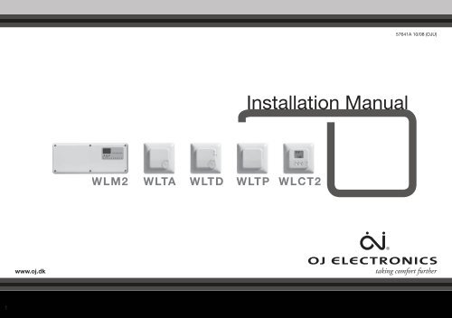
<strong>Installation</strong> <strong>Manual</strong><br />
WLM2 WLTA WLTD WLTP WLCT2<br />
www.oj.dk<br />
1
CONGRATULATIONS<br />
Congratulations with you new control system for<br />
underfloor heating and cooling.<br />
The control system has been developed to provide a<br />
temperature control system for room heating and cooling,<br />
integrating the switching of primary heating and cooling<br />
sources with the control of water temperature and mixing<br />
devices.<br />
This ensures the best possible comfort conditions and also<br />
reduces energy consumption.<br />
Highlights of the system (depending on equipment):<br />
:: Heating and cooling control for true comfort<br />
:: Humidity sensor to prevent condensation on floors<br />
:: Energy saving comfort with adaptive function<br />
:: Area control for easy operation<br />
:: Flexible installation for wired and wireless connection<br />
:: Network communication for large applications<br />
:: Easy installation with plug and lead connections<br />
:: Optional weather compensation<br />
2<br />
BR-0965-A10
INSTALLATION MANUAL<br />
CONTENT<br />
WLM2 Underfloor Heating Controller ..................4<br />
Description ............................................................................7<br />
Product Programme ..............................................................7<br />
Technical Data .......................................................................7<br />
Environment ..........................................................................8<br />
Recycling of obsolete appliances .........................................8<br />
Configuring the Total System ................................................8<br />
<strong>Installation</strong> ..............................................................9<br />
Electrical <strong>Installation</strong> .............................................................9<br />
Boiler Demand ......................................................................9<br />
Pump Output ......................................................................10<br />
Free relay function (X-OUTPUT) ..........................................10<br />
Thermal Actuators [Thermoheads] ......................................12<br />
External Switch (TIMER) for night setback ..........................12<br />
Room sensors - Bus Connection .......................................13<br />
Channel Setting ...................................................................14<br />
Room sensors - Wireless setup ..........................................15<br />
Supply water temperature sensor and mixing valve ...........16<br />
Special Functions ................................................17<br />
Creating a network ..............................................................17<br />
Using cooling functions .......................................................18<br />
Domestic hot water control .................................................19<br />
Radiator control ...................................................................20<br />
2 step heating ......................................................................20<br />
Commissioning mode ........................................................21<br />
Replacing equipment ..........................................22<br />
Replacing a faulty sensor/controller ....................................22<br />
Guidelines and Special Features........................23<br />
Power up recommendations ...............................................23<br />
Factory Default Settings ......................................................24<br />
Error Indication ....................................................................25<br />
Special Features ..................................................27<br />
Temperature & Control ........................................................27<br />
Emergency handling ...........................................28<br />
Exercise of valves ................................................28<br />
Add On Module ....................................................29<br />
Configuring the Total System ..............................................29<br />
Outdoor Compensation Module- Type WLOC-19 .30<br />
Introduction .........................................................................30<br />
Mounting .............................................................................30<br />
BUS CONNECTION - Outdoor Compensation Module ......30<br />
Interconnection of WLM2 products ...................31<br />
Interconnections ..................................................................31<br />
Waterline Wireless System .................................32<br />
Product Programme ............................................................32<br />
Connection of Master and Receiver ....................................32<br />
Position ................................................................................32<br />
Master .................................................................................32<br />
To set up the system ...........................................................32<br />
Type WLCT2 (and WLCT2/R/HW/2) ....................33<br />
Introduction .........................................................................33<br />
Getting Started ....................................................................33<br />
Daily Use of the room sensor ..............................................35<br />
Programming 4-Event Clock Time and Temperature ..........36<br />
Advanced Settings and Read-out .......................................37<br />
Reset to factory Settings - room controllers .......................41<br />
Waterline Room sensors ....................................42<br />
Introduction .........................................................................42<br />
Set-up ..................................................................................43<br />
Setting of Room Temperature .............................................44<br />
Setting of Room sensor Operating Mode ...........................44<br />
Limit Sensor - WLTD and WLCT2 .......................................45<br />
3
WLM2 Underfloor Heating Controller<br />
To Control X-OUTPUT for: DIP-5 DIP-6 DIP-7<br />
Boiler pump OFF OFF OFF<br />
High limit zone valve ON OFF OFF<br />
Cooling device/module OFF ON *<br />
Cooling device/module<br />
alternative<br />
ON ON *<br />
Differential thermostat OFF OFF ON<br />
4<br />
* ON = Actuator output no.1 is used as an ON/OFF signal<br />
for a dehumidifier
5<br />
WLM2 underfloor heating controller<br />
To Control X-OUTPUT for: DIP-5 DIP-6 DIP-7<br />
Boiler pump OFF OFF OFF<br />
High limit zone valve ON OFF OFF<br />
Cooling device/module OFF ON *<br />
Cooling device/module<br />
alternative<br />
ON ON *<br />
Differential thermostat OFF OFF ON<br />
* ON = Actuator output no.1 is used as an ON/OFF signal<br />
for a dehumidifier
6<br />
WLM2 underfloor heating controller
7<br />
WLM2 underfloor heating controller<br />
Description<br />
Product Programme<br />
Technical Data<br />
Type WLM2 underfloor heating controller is suitable for connecting multiple room Room sensors and<br />
electric actuators (thermoheads) for an underfloor or radiator based heating system.<br />
Room sensors requiring a 230V or 24V live & neutral must NOT be connected.<br />
Only OJ Room sensors type WLxx that are prepared for 2 wire or wireless communication<br />
can be used.<br />
Product Thermo Heads Type<br />
Master for 8 zones 230V AC WLM2-1BA (basic system)<br />
Master for 8 zones with display 230V AC WLM2-1FS (full system)<br />
Master for 8 zones 24V WLM2-3BA (basic system)<br />
Master for 8 zones with display 24V WLM2-3FS (full system)<br />
Add-on module for 6 zones 230V AC WLM2-1AO<br />
Add-on module for 6 zones 24V WLM2-3AO<br />
TECHNICAL DATA<br />
Power Supply .............................................................................................230V AC +10/-15%, 50 HZ<br />
Max load pumps and Thermal actuators .......................................................................................10A<br />
Boiler relay ........................................................................................................Volt free signal. Max 4A<br />
Main pump (free relay) .....................................................................................Volt free signal. Max 4A<br />
Secondary pump .............................................................................................230V AC, 50Hz Max. 4A<br />
Thermal actuators:<br />
WLM2-1BA ........................................................................................................................ 8 x 230V<br />
WLM2-1FS ........................................................................................................................ 8 x 230V<br />
WLM2-1AO ........................................................................................................................ 6 x 230V<br />
Max. 2A per output. Max. 5A in total<br />
WLM2-3BA .......................................................................................................................... 8 x 24V<br />
WLM2-3FS ........................................................................................................................... 8 x 24V<br />
WLM2-3AO .......................................................................................................................... 6 x 24V<br />
Max. 10VA per output. Max. 35VA in total<br />
Optional External Switch (Timer) for night setback ......................................... Open terminals for NSB<br />
Closed terminals for day operation<br />
Room sensor Bus 2 wire low voltage ................................................... bus signal from Room sensors<br />
RJ14 interconnection cables ...... CAT5 STP, max 300 meters between masters and 600 meters in total<br />
Additional data for WLM2-1FS & WLM2-3FS (not applicable to the basic version)<br />
Application sensor and Limit sensor ............................... NTC type ETF-1899A for water temperature<br />
Control signal for mixing valve actuator .................................................................................0-10V DC<br />
Power supply for mixing valve actuator ....................................................................24V AC. Max 6VA
Environment<br />
WLM2 underfloor heating controller<br />
Recycling of obsolete appliances<br />
Configuring the Total System<br />
Type WLM2-1BA and WLM2-3BA<br />
Type WLM2-1FS and WLM2-3FS<br />
Type WLM2-1AO and WLM2-3AO<br />
Please help us to protect the environment by disposing of the packaging in accordance with the<br />
national regulations for waste processing.<br />
Appliances with this label must not be disposed off with the general waste.<br />
They must be collected separately and disposed off according to local regulations.<br />
Each master module is capable of controlling 8 heating zones, each of which may use one or more<br />
loops of piping, with one or more thermal actuators.<br />
These zones are referred to later in this instruction as channels 1 to 8. If you wish to control more<br />
than 8 zones, it is necessary to install an ADD ON (AO) module, each of which can provide another 6<br />
outputs. The AO module then controls channels 9 to 14,<br />
1..8<br />
Green: Power supply connected<br />
Red: Night setback active<br />
Red flashing: Indicates error<br />
X-Output function is active (see section: “Free relay function”).<br />
Secondary UFH pump is running<br />
Boiler enable signal is activated<br />
Zone 1 to 8 indicating heating is on<br />
8
<strong>Installation</strong><br />
Electrical <strong>Installation</strong><br />
Fig. 3<br />
Fit the WLM2 master to a suitable wall. It will generally be found more convenient if the unit is within<br />
0.8 metre of the manifold, as most thermal actuators are supplied with 1m cables. Cables can be run<br />
on the surface into the terminals using either the cable releases in the cover or by pressing out the<br />
cable entries in the lower part of the cover.<br />
PLEASE ENSURE THAT ALL WIRING IS CARRIED OUT IN ACCORDANCE WITH<br />
LOCAL ELECTRICAL REGULATIONS.<br />
When wiring is completed, fit the cover on the master using the screws provided.<br />
Mains supply<br />
WLM2 requires a 230V AC mains supply connected to the terminals marked L, N, & E.<br />
Boiler Demand<br />
Fig. 4<br />
The master has a volt-free relay output that can be used to control a boiler, or to open a<br />
motorised valve.<br />
A) To control a boiler that requires switching of the live supply, take a link from L (230V) to the<br />
terminals marked BOILER - B1. Connect the boiler L to the terminal marked BOILER – B2.<br />
Connect the boiler N terminal to the N terminal on the master, and the boiler E to the master<br />
terminal E. (see fig. 7A).<br />
B) To control a boiler that has a pair of dedicated terminals for remote switching (e.g. by a Room<br />
sensor), connect these terminals to B1 and B2 on the master. B1 and B2 terminals are “volt free”<br />
so they can be used for both a 240V and a 24V circuit from the boiler.<br />
9
C) To control a motorised valve:<br />
Many motorised 2 port, spring return valves, have wires coloured BROWN and BLUE for power<br />
connections. In this case BROWN goes to the terminal B2 under the heading BOILER and BLUE<br />
goes to the N terminal of the master. Then a link from L (230V) to the terminals marked “Boiler<br />
B1”. The boiler relay will be energised after a delay of 10 sec after the start of the main pump.<br />
Basic versions without display. Type WLM2-1BA and WLM2-3BA The boiler relay will stop if<br />
there is no heat demand measured by the Room sensors.<br />
Versions with display. Type WLM2-1FS and WLM2-3FS.<br />
These units have supply water temperature control, and the boiler relay will be ON once the<br />
control valve has reached 20% open, and will remain on as long as a heat demand exists.<br />
<strong>Installation</strong><br />
Pump Output<br />
Fig. 5<br />
The master has an output for the underfloor circulating pump (secondary pump). The output will be<br />
energised after a 180 sec. delay when any connected room sensor calls for heat. The delay is to<br />
allow time for the thermal actuator to start opening.<br />
The 230v AC pump can be connected directly to terminals L and N under the heading “Sec. UFH<br />
Pump”. Connect the pump E (Earth) terminal to E (earth) on the master. The maximum pump load<br />
must not exceed 4 amps , 230v at start up. There is an overrun period of 1 minute after the demand<br />
for heat from the room sensor disappears.<br />
Delay times: Secondary UHF pump 180 sec.<br />
X-output (configured as main pump) 190 sec.<br />
Free relay function (X-OUTPUT)<br />
Fig. 6a<br />
All WLM master have a relay which can be<br />
utilized for a number of different purposes.<br />
The relay is a volt free output and is positioned<br />
on the PCB as shown on the drawing.<br />
The function of the relay is determined by the<br />
setting of the DIP-switches.<br />
The functions that the relay can perform, and the<br />
appropriate DIP-switch settings, are as follows:<br />
To Control X-OUTPUT for: DIP-5 DIP-6 DIP-7<br />
Boiler pump OFF OFF OFF<br />
High limit zone valve ON OFF OFF<br />
Cooling device/module OFF ON *<br />
Cooling device/module<br />
alternative<br />
ON ON *<br />
Differential thermostat OFF OFF ON<br />
10<br />
* ON = Actuator output no.1 is used as an ON/OFF signal<br />
for a dehumidifier
<strong>Installation</strong><br />
Fig. 6b<br />
The X relay output is volt free as shown in fig 8a. If the relay is required to be used as a L & N switch, connect a<br />
link wire from mains L to C1, connect the device L to C2, and the device N to mains N.<br />
Boiler pump:<br />
Where a boiler primary pump is required to be switched on from the master, the relay output can be used for this<br />
purpose. The relay will be activated 10 seconds after the UFH circulating pump has started.<br />
High Limit Zone Valve:<br />
This function is used where an additional protection is required to prevent boiler water entering the underfloor<br />
system, when the system is off or when the supply water exceeds 65 C.<br />
An additional sensor (ETF-1899A) called ‘Application Sensor’ as shown in fig. 8b and a zone valve is connected<br />
via the X-output (see example fig. 8c.)<br />
Cooling device/module:<br />
The relay output can be used to provide a volt free signal to a heatpump, or to a K-MOD switching module<br />
where a chiller is utilized to provide the cooling water. The relay is on when there is a cooling demand. (For more<br />
information see the section “Using cooling functions”.)<br />
Cooling device/module alternative:<br />
The relay output is always on in cooling mode and off in heating mode. (For more information see the section<br />
“Using cooling functions”.)<br />
Differential thermostat:<br />
The relay output can be used as an output that enables an alternative energy sources like solar energy.<br />
To use this, besides the supply water sensor, an additional sensor (ETF-1899A) called ‘Application Sensor’ is<br />
needed in the system, to detect the temperature in the water storage cylinder of the alternative energy source.<br />
If the system detects that this temperature (via the Application Sensor) is more than 3°C higher than the supply<br />
water temperature it activates the X-relay to select the alternative energy source by a valve and/or a pump.<br />
Fig. 6c<br />
11
Thermal Actuators [Thermoheads]<br />
Fig 6<br />
These actuators are fitted to the underfloor heating manifolds and control the supply of water through the<br />
various loops. The voltage of the thermal actuators, 230V or 24V, must correspond to the master.<br />
Master type WLM2-1BA and WLM2-1FS are for 230 V thermal actuators, and master type WLM2-3BA<br />
and WLM2-3FS are for 24V Thermal actuators. Up to 8 different zones can be controlled by the master.<br />
Connect the thermal actuators on the loop(s) for each zone to the corresponding terminals on the master.<br />
Thermal actuators belonging to zone 1 must be connected to output terminal 1, and thermal actuators for<br />
zone 2 must be connected to output terminal 2, etc, etc.<br />
<strong>Installation</strong><br />
External Switch (TIMER) for night setback<br />
Fig 7<br />
Guideline<br />
More than 1 head can be connected to a single terminal, provided that the heads are to be controlled by<br />
the same room Room sensors / Controllers.<br />
Connect the Brown wire to the L terminal, and the Blue wire to the N terminal. When the installation is<br />
complete, check that the Room sensor in e.g. room(zone) 1, operates the correct thermo actuator(s) for<br />
that room on the manifold. If the heads appear to be in the wrong position on the manifold, it may be<br />
simpler to change them on the manifold, rather than reconnecting them on the master.<br />
From factory the master is delivered with a jumper in the switch/ timer terminals I & O. The current<br />
operating set point of the master can be changed from the day temperature into night temperature, and<br />
vice versa by using an input from an external switch or timer. The input must be a volt free switch, and<br />
will need to open circuit for night temperature and close circuit for day temperature. When the external<br />
switch or timer is used to switch to night setback, this will override any time settings in a WLCT Room<br />
controller, including any Room sensors that are part of a group allocated to that Room controller.<br />
12
Room sensors - Bus Connection<br />
Fig 9<br />
Only OJ Room sensors type WLxx that are prepared for 2 wire communication can be used. Standard<br />
installation cable, maximum 2 x 0.25 mm 2 can be used. The Room sensors can be connected in the<br />
conventional star wiring format, or in a bus connected mode (Daisy chain) see fig 10 + fig 11. The<br />
master has 4 sets of terminals marked Room sensor BUS that can be used for connecting the 2-wire<br />
signal from the Room sensors.<br />
There are 4 identical sets of terminals for convenient installation. Any Room sensor can be connected<br />
to any pair of terminals. The total length of the 2-wire system can be up to 300 m with a maximum<br />
length of 100mbetween any 2 Room sensors.<br />
Remember to connect + to + and – to – .<br />
<strong>Installation</strong><br />
SENSORS/CONTROLLERS CONNECTED IN STAR<br />
Fig 10 Fig 11<br />
SENSORS/CONTROLLERS CONNECTED IN BUS MODE<br />
(DAISY CHAIN)<br />
13
Channel Setting<br />
Fig 10<br />
Each Room sensor can be selected to operate a specific output which in turn controls the thermal<br />
actuators on the manifold. Under the front cover of the Room sensor, a selector can be accessed,<br />
and the number of its output (its CH channel) can be set with a screwdriver. (See fig 10) Up to 14<br />
channels can be set on the selector, and there are two auxiliary channels. (see later). A WLM2<br />
master has 8 outputs and additional slave module 6 outputs, and can be connected creating a<br />
system of 14 individual zones.<br />
Please note that channels 10 to 14 are marked as A through E on the selector,<br />
<strong>Installation</strong><br />
A Room sensor set for CH1 will activate the thermal actuator connected to output 1 on the master.<br />
The channel number can be selected without any power connected to the system. The channel of<br />
the Room sensor can be changed afterwards if needed.<br />
If two Room sensors are placed in the same room and set to the same channel, the temperature<br />
control will work according to the average temperature of both Room sensors.<br />
Channel 0:<br />
Each Room sensor is delivered with the switch in position 0 ensuring that it must be set to operate<br />
correctly. Channel 0 can also be used for a Room controller controlling a group of Room sensors<br />
where the control position should be somewhere central, e.g. the kitchen, rather than in the area<br />
where the Room sensors are installed. Setting it to Ch 0 means that times and temperatures are<br />
set on the WLCT2 for the group, but that the WLCT2 will not control a specific output itself.<br />
Channels 1..14:<br />
A Room sensor set for channel 1 will activate the thermal actuator connected to output 1 on<br />
the master. If several Room sensors are set to the same channel number, they will control in the<br />
following way,<br />
- The actual room temperature is calculated as an average.<br />
- The room temperature set point is calculated as an average.<br />
- If a limit sensor is connected to the Room sensors<br />
The lowest value of any Limit sensor is taken as the MIN Limit Temperature.<br />
The highest value of any Limit sensor is taken as the Max Limit Temperature.<br />
Channel 15: (position F on the switch) Party and vacation function.<br />
Special function. Further instructions in “Special Features”.<br />
Testing the system: See ”Guidelines and Special Features – Power up recommendations”<br />
14
Room sensors - Wireless setup<br />
Fig 12<br />
Where wireless Room sensors/controllers (WLTx-29) are being used is necessary for the WLM2 master to<br />
“learn” that the Room sensors/controllers are communicating correctly.<br />
<strong>Installation</strong><br />
Fig 13<br />
To achieve this:<br />
1. On master, switch on DIP-3 to activate learn mode:<br />
2. All wireless Room sensors/controllers now have to be initialized:<br />
Room sensors (WLTA, WLTD, WLTM, WLTP) by pressing the internal init button<br />
(Button learning mode) until a beep is heard. (see fig. 12)<br />
Room controllers (WLCT2) by pressing the pin hole button with the clock symbol until a beep is<br />
heard. (see fig. 13)<br />
3. Switch off DIP-3 to de-activate learn mode.<br />
Button learning mode<br />
15
Supply water temperature sensor and mixing valve<br />
<strong>Installation</strong><br />
Fig 11a<br />
Fig 11b<br />
Supply water temperature limit sensor<br />
This feature is available on the full system masters WLM2-1FS & WLM2-3FS.<br />
The limit sensor is directly connected to the master at the terminals marked supply sensor. Sensor<br />
type ETF-1899A must be used.<br />
The temperature sensor should be placed on the supply water pipe to the underfloor heating<br />
system, If a limit sensor is installed, without a weather compensation module (WLOC) the master<br />
will control the design supply water temperature. The factory default setting can be changed via the<br />
display.<br />
If a weather compensation module (WLOC) is added to the system, the master will vary the supply<br />
water temperature setting based on the outdoor temperature. A standard compensation curve<br />
has been programmed at the factory. If needed the curve can be changed, see separate USER<br />
MANUAL, MASTER TYPE WLM2.<br />
Mixing valve actuator control<br />
Control of a mixing valve actuator is possible using the digital masters WLM2-1FS and WLM2-3FS<br />
The actuator must be 24Vac powered (max 6VA) and positioned via the 0-10V DC signal, and<br />
should be configured so that it closes the valve if there is no heating demand (0Vdc signal). The<br />
control signal can be reversed to 10-0V via the master menu system if required.<br />
Control action of the mixing valve actuator is P + I and the parameters can be<br />
changed if required in the master menu system.<br />
Please contact the supplier for further instructions.<br />
16
Special Functions<br />
Creating a network<br />
Fig 12a<br />
In large buildings with more than 14 zones where multiple manifolds are<br />
utilized, it is possible to use multiple masters to create a single network.<br />
One master must be defined as the “network controlling master” by<br />
setting both encoders to zero (see fig.12a,12b).<br />
Subsequent masters (up to nine) should be connected as a “string”,<br />
where they will all use a common pump.<br />
If more than one pump is used, a separate string should be created for<br />
each pump (see fig.12a).<br />
On the first string all left hand encoders must be set to 1, and the right<br />
hand encoders should be set in sequence from 1 to 9.<br />
On the second string of masters all left hand encoders should be set to<br />
2, and the right hand encoders again should be set in sequence from 1<br />
to 9. This numbering can be continued for up to 15 strings.<br />
All Masters are interconnected using special cable via the RJ14 socket 1 or<br />
2. (For further information see section “Interconnection of WLM2 products”.)<br />
All masters must be connected in a daisy chain connection, and NOT in<br />
a star connection (see fig.12c).<br />
Fig 12b<br />
An FS master can be used as the “network controlling master” for<br />
central mixing control of supply water and boiler switching.<br />
Switching between cooling and heating can be done for the whole<br />
network on the “network controlling master” using the WLAC-1 interface<br />
module connected to the thermostat bus.<br />
Time and temperatures for the whole network can be controlled by a single<br />
WLCT2 connected to the “network controlling master” if the WLCT2 is set<br />
to channel F.<br />
Fig 12c<br />
17
Special Functions<br />
18<br />
Using cooling functions<br />
Type WLH-19<br />
• A network must always contain a network controlling master.<br />
• On masters set to the same string (same setting on the left encoder), all pumps, boiler and valve<br />
outputs will act simultaneously enabling the use of a common pump on each string.<br />
• If only one UHF pump is used in a network, DIP-8 on the network controlling master can be set to<br />
“ON” enabling the UHF-pump output on this master to control a common pump for the whole system.<br />
• All masters in a network follows the same synchronized timing for actuators, pumps, boilers and<br />
mixing valve output.<br />
• If a lower supply water temperature is needed on one of the strings, the first master on this string can<br />
be a FS master with a local mixing valve and supply water sensor attached.<br />
• On FS masters a special menu is available on the network master when a network is detected.<br />
With this menu it is possible to check the network. Please refer to the USER MANUAL for further<br />
instructions.<br />
Note: To test a network please refer to section “Power up recommendations”.<br />
In addition to controlling heating, all WLM2 masters have the ability to control the system for cooling.<br />
• To enable the cooling function an interface module WLAC and humidity sensor WLH have to be<br />
connected.<br />
• To use the X-relay as a cooling signal controlling, a chiller, a reversible heat pump or<br />
diverting valves, please refer to the section “Free relay function (X-OUTPUT)”.<br />
• On BA masters it is also necessary to install a sensor (ETF-1899) on the return water pipework<br />
from the floor for dewpoint control. The sensor must be connected to terminal 49 and 50.<br />
Using the WLAC-1 module:<br />
• The WLAC must be fixed in a convenient position for the user, and connected to the sensor/<br />
controller bus as shown in the drawing.<br />
• If a BMS system in being used for the heating/cooling decision, the volt free BMS signal (EXT) should<br />
be connected to the WLAC but the slider switch on the right side of the WLAC must be set to the<br />
heating position (in this situation the BMS signal has priority and we recommend that the slider<br />
toggle be removed to avoid incorrect overriding)<br />
Humidity sensor WLH-19:<br />
• By using the humidity sensor WLH the system limits the formation of condensation on floor<br />
surfaces due to high humidity.<br />
• The WLH must be fixed in a room that represents the general humidity level in the building, and<br />
connected to the sensor/controller bus (more than one WLH can be used if necessary e.g. on<br />
separate floors of the building). Where more than one humidity sensor is used, the master will<br />
take the reading of the sensor detecting the highest DEW point level for the controlling action.
• If a dehumidifier is being used it can be connected via a relay using number 1 output on the master<br />
and setting DIP-7 to “on”. (Note: This output gives either 24Vac or 230Vac depending on the WLM2<br />
master type. Channel number 1 cannot be used for Room controller control in this situation)<br />
• When cooling is enabled the cooling set point will be pre-determined by the master and will override<br />
any settings in any Room controller to ensure optimum energy efficiency. (The cooling set point will<br />
be +3C above the master day set point)<br />
Special Functions<br />
Domestic hot water control<br />
It is possible to control the domestic hot water temperature with a special controller (WLCT2/HW) to<br />
ensure optimum energy saving.<br />
A hot water sensor is connected to the controller and measures the temperature in the storage cylinder.<br />
A zone valve is then controlled via the WLM2 master, which in turn activates the boiler on demand.<br />
• Install the hot water senser (ETF) on the hot water take off pipe immediately above the storage<br />
cylinder. Use the fixing strap to mount it tight to the surface.<br />
• The WLCT2/HW must be fixed in convenient position for the user<br />
• Connect the hot water controller WLCT2/HW to the WLM2 master using the sensor/controller bus.<br />
• Connect the hot water sensor to the controllers sensor terminals.<br />
• Connect the hot water zone valve to an output on the WLM2 master and set the channel number<br />
on the hot water controller to the corresponding number.<br />
The hot water controller is available in wired or wireless version.<br />
Note: When the WLCT2/HW calls for heat it does not start the circulation pump on the under floor<br />
heating system<br />
Type<br />
WLCT2/HW<br />
19
Radiator control<br />
It is possible to control a radiator circuit room temperature with a special controller<br />
(WLCT2/R) to ensure optimum energy saving.<br />
The controller measures the temperature in the room, and a zone valve is then controlled<br />
via the WLM2 master, which in turn activates the boiler on demand.<br />
• The WLCT2/R must be fixed in a convenient position for the user, but which is<br />
representative of the room or area temperature.<br />
• Connect the controller to the WLM2 master using the sensor/controller bus.<br />
• Connect the radiator zone valve to an output on the WLM2 master and set the<br />
channel number on the Room controller to the corresponding number.<br />
• The special Radiator controller is available in wired or wireless version.<br />
Special Functions<br />
2 step heating<br />
Type WLCT2/R<br />
Note: When the WLCT2/R calls for heat it does not start the circulation pump on the<br />
under floor heating system. While the System is in Cooling mode, all radiator circuits will<br />
be off.<br />
Type WLCT2/2<br />
It is possible to control a secondary heat source in a room (e.g. a<br />
backup radiator), use the special mode in the WLCT2/2 controller.<br />
In addition to the primary underfloor heating output, this WLCT2/2<br />
controller is able to control a second output as a boost function,<br />
which will be activated only if the temperature cannot be achieved by<br />
the underfloor heating within a preset time period.<br />
• The WLCT2/2 must be fixed in a convenient position for the user,<br />
but which is representative of the room or area temperature.<br />
• Connect the controller to the WLM2 master using the sensor/<br />
controller bus.<br />
• Set the channel number on controller to correspond with the<br />
output on the WLM2 master that is connected to the underfloor<br />
heating actuator.<br />
• The next numerical output on the WLM2 master MUST be used for<br />
the secondary/boost function.<br />
• While the system is in cooling mode, step 2 will be disabled<br />
• The 2-step controller is available in wired or wireless version.<br />
20<br />
Note: To avoid overloading the WLM2 master, we recommend that the<br />
secondary output is used as a signalling function for a remote relay.<br />
Please refer to the technical information.
Commissioning mode<br />
Supply temp.<br />
Max.<br />
Digital masters include a special “commissioning mode”, which allows the temperature of the supply<br />
water to be controlled to assist the drying out of a newly laid concrete floor.<br />
To start this function:<br />
• Set DIP-4 to “on”.<br />
• This will set the supply water temperature at 23c for three days and will fully open all the manifold<br />
actuators.<br />
• Then for a further four days the water will be supplied at the maximum supply water temperature,<br />
as set in the WLM master menu, and during this period the manifold actuators will remain fully open.<br />
Special Functions<br />
23˚C<br />
1 2 3 4 5 6 6<br />
• When the WLM master is operating the commissioning function this is indicated by the output<br />
LED’s flashing in rotation and with the word “commissioning” flashing in the display.<br />
• The commissioning function time periods are paused if the power supply is interrupted.<br />
• Should you need to restart the commissioning from the beginning, switch DIP-4 to “OFF” and<br />
back to “ON”.<br />
• To de-activate the function switch DIP-4 to “OFF”.<br />
• After 7 days the commissioning mode is ended and normal operation is re-established (even with<br />
DIP-4 on)<br />
Note: This function conforms to BS/EN-1264 part 4.<br />
21
Replacing equipment<br />
Replacing a faulty sensor/controller<br />
1. Identify the sensor/controller to be changed by the blinking output LED.<br />
2. Switch OFF power to the master<br />
3. Change the sensor/controller.<br />
Important: Set the channel selector on the new sensor/controller to the same channel as the<br />
defective sensor/controller that is replaced<br />
4. Switch ON power to the master<br />
5. Set the master into learnmode and set DIP-3 to ON.<br />
6. On wireless sensor/controller now press the button on the sensor/controller.<br />
On hardwired sensor/controller go to step 7.<br />
7. Check that the corresponding output LED has changed from blinking to permanently ON.<br />
8. Reset the DIP-3 to OFF.<br />
For any other changes in the system use the quick guide and start the install sequence from the<br />
beginning.<br />
22
Guidelines and Special Features<br />
23<br />
Power up recommendations<br />
TOTAL X<br />
ERROR ON IDxx<br />
When all connections are complete we highly recommend that the connections between the sensors and<br />
the thermo heads are tested by following the sequence below:<br />
System check:<br />
Correct operation of the system can be checked using a special “Install Mode”.<br />
This enables the installer to individually test and prove each output.<br />
Testing the system:<br />
1. Switch on DIP-3 to activate learn mode: - power light will blink quickly<br />
2. Each red channel light on the master should now be lit if a sensor/controller is present on that channel.<br />
3. Switch off DIP-3 to de-activate learn mode again – power light stops blinking.<br />
4. Turn all adjustable temperature settings on the sensor/controller to minimum.<br />
5. Switch on DIP-1 on the master to activate install mode (Install mode will be active for 2 hours).<br />
(Pumps, boiler, mixing valve and actuators should now be off)<br />
6. Turn the temperature setting on the adjustable sensor/controller in room 1 to maximum.<br />
The red channel 1 light should be lit and the actuator on output nr. 1 will be activated, and will<br />
open after 1-3 minutes, depending on the type of actuator.<br />
Important: If the sensor/controller is of a wireless type a delay of up to 5 minutes may occur before<br />
the channel light becomes illuminated. Boiler will not operate during test mode, unless DIP 2 is<br />
activated, see step 9 below.<br />
7. Check that the UHF pump is running and the mixing valve (only FS master) opens.<br />
8. Repeat step 2 on all rooms.<br />
9. Boiler test function: Switch on DIP-2. This closes the boiler start relay contacts for 1 minute.<br />
10. To end all tests:<br />
- Switch off DIP-1 to deactivate Install mode<br />
- Switch off DIP-2 to deactivate boiler test.<br />
- Set all temperature knobs to default positions<br />
Room sensors (WLTA, WLTD, WLTM, WLTP) to zero (center position).<br />
Room controllers (WLCT2) recommended to 21c.<br />
- Set all override switches on WLTM and WLTD room sensors to automatic position (clock symbol).<br />
Testing a network:<br />
If a network of masters has been set up, the communication between these must be tested.<br />
When the slave masters are in install mode (DIP-1 is ON) the power LED will flash shortly every time a<br />
communication is detected (approx. every 3 sec). On an WLM2-xFS network master there is a menu<br />
entry that gives a possibility to check how many masters are present on the system and if they have any<br />
errors. (please refer to the userguide about the menu)<br />
The system is now operating automatically.
Factory Default Settings<br />
Master Settings Factory<br />
settings<br />
BA/FS Day temperature 21˚C<br />
Own<br />
settings<br />
Additional information<br />
Master Settings Factory settings<br />
BA/FS Cooling mode Day cooling<br />
temperature<br />
Day heat temperature + 3°C<br />
Night temperature<br />
18˚C<br />
Off temperature<br />
5˚C<br />
Floor Limit temp high<br />
27˚C<br />
Floor Limit temp low<br />
17˚C<br />
FS Max water temperature 55˚C<br />
Weather compensation<br />
Cold (winter)<br />
Weather compensation<br />
Warm (summer)<br />
Outdoor temperature -3˚C<br />
Water temperature 45˚C<br />
Outdoor temperature 20˚C<br />
Water temperature 25˚C<br />
Room temperature<br />
control<br />
Floor Limit<br />
temperature<br />
control<br />
Adaptive PWM<br />
control<br />
Max number<br />
of connected<br />
sensors<br />
Night cooling<br />
temperature<br />
Day cooling temperature + 3°C<br />
DEW point safety zone DEW point + 3°C<br />
PI - control P = 4°C<br />
I = 90-180 sec<br />
K-factor = 0.1<br />
P - control P = 4°C<br />
Max allowed Room<br />
temperature fluctuation<br />
Self adjusting<br />
(adaptive) PWM time<br />
interval limits<br />
Wired and wireless 24<br />
+/- 0.5°C<br />
15 – 45 minutes<br />
Sensor timeouts Wired 300 sec. (5 min)<br />
FS<br />
Wireless<br />
Minimum cooling<br />
supply water<br />
temperature<br />
10000 sec. (2h 45 min)<br />
16°C<br />
Supply water<br />
temperature<br />
control<br />
PI - control P = 20°C<br />
I = 300 sec.<br />
K-factor = 0.05<br />
24Guidelines and Special Features
Error Indication<br />
During normal operation the power LED will be ON when the master control is energised. The red output Channel LED’s<br />
(1 to 8 on the master, and 9 to 14 on the add-on module) will indicate if the channel output relay is ON/OFF.<br />
Guidelines and Special Features<br />
25<br />
An error / fault message is shown by flashing the power LED or one of the red output Channel LED’s. From the number of flashes<br />
on any one LED, the problem can be diagnosed, and identified from the following:<br />
The error number will be indicated by the number of flashes, with a pause of less than a 1/2 second between the flashes. The indication will be followed<br />
by a pause of 2 seconds, following which the sequence will be repeated. The failure code can also be seen in the service menu on WLM2-FS MASTERS<br />
(submenu 2).<br />
Flashing Power LED (Red and green)<br />
Communication to the network has errors. On the network master it tells that one or more masters are not communicating. On a network slave it tells that<br />
communication to the network master is missing.<br />
Flashing Power LED (Red)<br />
E1, 1 flash One or more room sensors, room controllers, WLH, WLAC that are set to channel 0 or channel 15 are no longer sending data to the<br />
master control. The fault is corrected by replacing the room sensor. The master will need to be HARD RESET (see next page)<br />
(NOTE: If the room sensor is of the WIRELESS type, the error/fault message could be an indication that the power has failed,<br />
and that the internal battery of the room sensor needs to be replaced)<br />
E2, 2 flashes One or more room sensors have been set to a channel number which does not exist in the system. For example, the message will occur<br />
if the units are set to channels 9-14 and the required add on (AO) module are not found in the system. The error is corrected by setting<br />
the channel number of the room sensor to a channel that does exist within the installed master/add on module system.<br />
E3, 3 flashes Application sensor defect. The fault is corrected by changing the temperature sensor. If the sensor has been removed deliberately to<br />
change the operation of the system, follow the HARD RESET instruction see next page.<br />
E4, 4 flashes The outdoor compensation module (WLOC) is defective. The fault is corrected by changing the outdoor compensation module.<br />
If the module has been removed deliberately to change the operation of the system, follow the HARD RESET instruction see next page.<br />
E5, 5 flashes The external Supply limit sensor (type ETF-1899A) is defective. The fault is corrected by changing the temperature sensor. If the<br />
sensor has been removed deliberately to change the operation of the system, follow the HARD RESET instruction see next page.<br />
E6, 6 flashes Internal overheating. The master has its own internal safety temperature protection system. The problem is corrected by improving the<br />
ventilation around the master module.<br />
E7, 7 flashes Defective internal overheat sensor. The Master will control as normal, however the protection against internal over heating is no<br />
longer active. The fault can only be corrected by replacing the master module.<br />
E8, 8 flashes The communication to the AO module has been lost. The fault is corrected by re-establishing the connection to the AO module or by<br />
changing the AO module if it is defective - or if it has been deliberately removed, with a HARD RESET.<br />
E9, 9 flashes Indicates total number of input units exceeded. Please refer to factory or your local service engineer.<br />
E10, 10 flashes No connection to wireless receiver, type WLRC2-19.<br />
E11, 11 flashes Step 2 on 2-step controller (WLCT2-X9/2) is used by another room sensor/controller.<br />
Only one error/fault condition can be shown at a time. If more than one error occurs, they will be prioritised in the shown sequence (E1, 2, 3…).
Flashing output LED (red):<br />
The appropriate output channel LED can flash, indicating that the room sensor or room contoller on that channel has a fault/error. The failure code can<br />
also be seen in the service menu (submenu 2a).<br />
Guidelines and Special Features<br />
E1, 1 flash The master has lost communication to the room sensor. The fault is corrected by re-establishing the connection to the Room<br />
Sensor and the fault condition will be automatically reset once correct communication is resumed. If the room sensor is<br />
defective and has to be changed, or if it has been deliberately removed, it is necessary to make a HARD RESET. (NOTE: If the<br />
room sensor is of the WIRELESS type, the error/fault message could be an indication that the power has failed, and that the<br />
internal battery of the room sensor needs to be replaced)<br />
E2, 2 flashes The internal sensor in the room sensor/controller is defective. The fault can only be corrected by replacing the room sensor/<br />
Controller. Remember to make a HARD RESET after installing the new room sensor/controller.<br />
E3, 3 flashes The limit sensor on the room sensor/controller is defective. Replace the faulty sensor. Reset is NOT required.<br />
E4, 4 flashes Defective WLCT2 room controller. If a room controller operating a group of room sensors becomes defective, the remaining<br />
room sensors will continue control within the maximum and minimum limits programmed into the Room controller.<br />
E5, 5 flashes Two or more room controllers are trying to control this output. Check “AREA” setting on the room controllers.<br />
E6, 6 flashes Channel output number one is configured as a dehumidifier output, error caused by a room sensor/controller also being set to<br />
control this output.<br />
RESET<br />
There are 2 different reset actions that can be used.<br />
HARD RESET<br />
If the ‘✓’ button is pressed for 5 seconds, a HARD RESET will be initiated. (Indicated by all the red output LED’s(1-8) lighting in sequence). This reset<br />
will remove from the system any room sensor unit with a defective input sensor, or a defective AO module. The fault message will be reset but the<br />
defective items will no longer participate in the system. To add or replace a new unit, please refer to “Replacing equipment - Replacing a faulty sensor/<br />
controller”. To erase the identity of the defective component from the master memory a HARD RESET must be performed Hard resets do not alter the<br />
temperature settings already programmed into the master control.<br />
FACTORY RESET<br />
If the (√ ) button is pressed for more than 15 seconds, a total factory reset will be initiated. This is indicated through flashes of channel LEDs 1,3, 5 and<br />
7 alternating with channel LEDs 2, 4, 6 and 8 (while the “√” button is pressed).<br />
A factory reset will put all programmed temperature settings back to the factory defaults. It will also remove all room sensors/Controllers from the<br />
master memory, and reset the system to accept only those room sensors/Controllers that are functioning correctly.<br />
To reconnect room sensors/controllers, please refer to “Replacing equipment - Replacing a faulty sensor/controller”.<br />
26
Special Features<br />
Temperature & Control<br />
TEMPERATURE SETTING<br />
For the master with display, the setpoints can be altered on the display.<br />
Each Room sensor with manual adjustment is capable of increasing or decreasing the preset DAY &<br />
NIGHT setpoints on the master by +/- 4C for the heating zone which it is controlling.<br />
The Room controller WLCT2 has its own DAY & NIGHT temperature settings that can be set separately,<br />
and if manual Room sensors are attached to its ”group” these will operate to the same settings as the<br />
WLCT2, but still with the possibility of local ±4°C adjustment.<br />
OVERRIDE FACILITY<br />
CHANNEL F OPERATION (Channel 15)<br />
By fitting a WLTM2-x9 sensor to any WLM2 system, and setting the hex-coder to Channel F, it is possible<br />
to override all the automatic time and temperature functions of the master control, including those areas<br />
independently controlled by a WLCT2-x9 room controller, with a single override function. This can be<br />
especially useful for long periods where overrides would be beneficial, this many include holidays and<br />
periods of un-occupation (where a frost protection level needs to be maintained).<br />
If a WLTM2-x9 has been set to Channel F on your system the override could not be simpler. On the right<br />
hand side of the control is a slide switch with four positions, each one of these affect the functionality of<br />
the system;<br />
AUTO – This will allow the system to run normally from the timings set on the WLM2 master and any<br />
WLCT2-x9’s<br />
DAY - This will keep the system working to the ‘Day’ temperature set point. Any WLCT2-x9’s, or sensor<br />
controlled by them, will not be affected by this operation.<br />
NIGHT - This will keep the system working to the ‘Night’ temperature set point. Any WLCT2-x9’s, or<br />
sensor controlled by them, will not be affected by this operation.<br />
OFF – This will effectively turn the system OFF, there is still a ‘Frost Protection’ level of 5oC in operation<br />
during this function.<br />
If you would like this functionality added to your existing system please consult you installer or service<br />
engineer.<br />
EXTERNAL TIMER (see also section “<strong>Installation</strong> - External switch”)<br />
The external switch or timer function on the master module allows the whole system to be changed from<br />
the DAY Setpoint to the NIGHT Setpoint.<br />
The external switch must have volt free contacts that are OPEN for NIGHT Setpoint, and CLOSED for<br />
DAY Setpoint. The factory fitted link wire is removed when a remote switch/timer is used.<br />
If a WLCT2 Room controller is employed in a part of the system, the external switch action of going to<br />
NIGHT Setpoint will override the Room controller.<br />
27
Emergency handling<br />
Emergency program for room control<br />
- If a Room sensor/controller is defective or if the communication to the unit is interrupted, an alarm will<br />
be triggered. Depending on the system configuration the regulation will continue in one of the following<br />
ways,<br />
- If there are several units on the same channel which have a room sensor (which is still intact), the<br />
regulation will continue as before, however without contribution from the defective unit<br />
- If no valid room sensor/controller is found, the system will run at constantly 20% ON<br />
- If an outdoor sensor is connected, the system will run 40% at 10°C (and Below) decreasing to 0%<br />
at 20°C (and above).<br />
The emergency program is only valid for channels with heat controls, channels with cooling control will<br />
always run at 100% OFF in connection with a defective room sensor’ Should this not read ‘The emergency<br />
program above is only on heating only installations. On heating and cooling installations, and only during<br />
cooling periods, the system will always run at 100% OFF in connection with a defective room sensor.<br />
Emergency program for supply limit sensor<br />
- If the supply limit sensor is deffective, the system will run at constantly 20% on for the valve.<br />
- If an outdoor sensor is connected, the system will run 40% at 10°C (and Below) decreasing to 0%<br />
at 20°C (and above).<br />
Exercise of valves<br />
If no automatic on/off sequence of valves or pumps occurs over a 72 hour period, an exercise of these<br />
components will take place. The actuators will be activated for 3 minutes. The pumps will be started for<br />
10 secs during that period, and the mixing valve, if fitted will be opened and closed.<br />
28
Add On Module<br />
Configuring the Total System<br />
Each master module is capable of controlling 8 heating zones, each of which may use one or more<br />
loops of piping, with one or more thermal actuators. These zones are referred to as channels 1<br />
to 8. If you wish to control more than 8 zones, it is necessary to install an add-on (WLM2-xAO)<br />
module which provides another 6 outputs.<br />
The AO module then controls channels 9 to 14 (9-E on the hex coder).<br />
Connection of master and add on module<br />
Connect the AO-module, using the special cable included in the box.<br />
Mains supply from 230V fused isolator.<br />
The sensor bus can be connected to either the WLM2 master or Add-on module, using either bus<br />
(daisy chain) or star connections. Thermal actuators 1-8 are controlled by the WLM2 master and<br />
9-14 are controlled by the Add-On module.<br />
29
Outdoor Compensation Module- Type WLOC-19<br />
Introduction<br />
Mounting<br />
The masters WLM2-1FS and WLM2-3FS are supplied already prepared for weather compensation<br />
and simply by adding the outdoor compensation module on the 2-wire bus and using the water<br />
temperature sensor on the supply water side, you have a control system for weather compensation.<br />
Preset values are programmed at the factory, but these values can easily be adjusted according to<br />
local needs via the display on the master. See the user manual ”Master with display type WLM” for<br />
changing of the default factory settings<br />
The outdoor compensation module is mounted under the roof eaves, alternative 2-3 m above ground<br />
level. Direct sunlight or any other direct heating source such as air ventilation must be avoided. The<br />
outdoor compensation module is mounted vertically with the cable entry downwards.<br />
BUS CONNECTION - Outdoor Compensation Module<br />
Only OJ Outdoor Compensation Modules type WLOC-19 that are prepared for 2 wire<br />
communication can be used.<br />
Standard installation cable, minimum 2 x0.25 mm2 can be used. The outdoor compensation module<br />
can be connected in the conventional star wiring format, or in a bus connected mode (Daisy chain).<br />
The master has 4 sets of terminals marked Room sensor BUS that can be used for connecting the<br />
2-wire signal from the Room sensors and the outdoor compensation module.<br />
There are 4 identical sets of terminals for convenient installation. Any Room sensor / outdoor<br />
compensation module can be connected to any pair of terminals. The total length of the 2-wire<br />
system can be up to 300 m with a maximum length of 100 m between any 2 Room sensors / outdoor<br />
compensation module. Remember to connect + to + and - to -.<br />
30
Interconnection of WLM2 products<br />
Interconnections<br />
For easy installation, interconnections between master modules, master and add on modules, and<br />
master and wireless receivers, are made by pre-wired plug in connectors (RJ14) For connecting<br />
WLM2 add on modules to WLM2 masters, a plug in connector is provided with the add on module.<br />
A WLRC wireless receiver is also connected to a WLM2 master, using the plug in connector provided<br />
with the receiver.<br />
For connecting a WLM2 master to another master in a network, a plug in connector kit (WLM-NET) is<br />
available. CAT5 STP cable should always be used.<br />
If a kit is not used it is possible to do the connection by using a standard RJ14 connection. In this<br />
case it must be ensured terminal 1 is connected to terminal 1 in the other end and so on.<br />
The same type of connection can be used from Master to AO module.<br />
RJ14<br />
* These connections are not necessary<br />
but are allowed<br />
31
Waterline Wireless System<br />
Product Programme<br />
WLRC2-19 Receiver<br />
Technical Data<br />
Supply Voltage . . . . . . . . . . . . . . 24 V from Master<br />
Distance to master . . . . . . . . . . . . . . . . . . Max 3 m<br />
Enclosure . . . . . . . .... . . . . . . . . . . . . . . . . . . IP 21<br />
Ambient temperature range . . . . . . . . . . 0 to 40°C<br />
Communication Frequency . . . . . . . . . . . 868 MHz<br />
Communication distance . . . . . Up to 30 m inside,<br />
. . . . . . . . . . . . . . . . . . . . . . . . Up to 100 m outside<br />
Connection of Master and Receiver<br />
B A -- +<br />
Blue Red Brown Yellow<br />
The receiver is connected to the master or the add on module using the included cable.<br />
Max distance between the master/add on module and receiver is 3 m. Two receivers can be<br />
connected to a master, or master/add on system, using the RJ sockets provided. Additional<br />
receivers can be connected if necessary – please refer to the dealers technical department. The<br />
wiring of the master and add-on module and receiver must be made by using the RJ14 connection<br />
points supplied.<br />
Position<br />
Do not place the receiver inside a metal box. In case of communication problems it may be necessary<br />
to move the location of the receiver, or to add an additional receiver.<br />
Master<br />
Connect the receiver to the master, and the system will reconfigure itself for wireless operation.<br />
To set up the system<br />
See Quickguide<br />
32
Type WLCT2 (and WLCT2/R/HW/2)<br />
Type WLCT2 (and WLCT2/R/HW/2)<br />
Introduction<br />
Getting Started<br />
Fig1<br />
The room controller type WLCT2-x9 is a 4 event programmable controller used to control underfloor heating areas<br />
or special features on the WLM2 installation. The standard WLCT2-x9 can be used to programme up to 4 time and<br />
temperature events over a 24 hour period, based upon a 7 day setting. Once a WLCT2-x9 has been fitted the times and<br />
temperatures for the area(s) it controls will no longer come from the defaults set in the main WLM2 master.<br />
In addition to the immediate area of control set, within the WLCT2-x9, and selected via the ‘AREA’ setting contained within its<br />
internal menu, the WLCT2-x9 can control the time and temperature characteristics of other sensor (up to 14) fitted to the WLM2<br />
master, this has been designed to maximise comfort and efficiency and promote energy saving and associated cost savings.<br />
Where the WLCT2-x9 is controlling other areas the +/- 4°C setting of those areas will now operate from the WLCT2-x9<br />
settings, e.g. A WLCT2-x9 is set to 22°C and has been given control over ‘Area 1’, the WLTA-x9 fitted in ‘Area 1’ now has<br />
a control range of 18°C(-4°C) to 24°C (+4°C).<br />
In addition to the standard WLCT2-x9 room controller, you may have fitted to your system one of the following;<br />
WLCT2-x9/2: This control allows the operation of a secondary heat source, for a specific area, as a boost function<br />
operating in conjunction with the underfloor heating.<br />
WLCT2-x9/R: This control is used for the control of radiators in a domestic central heating circuit.<br />
WLCT2-x9/HW: This control is used for the production of hot water control within a system.<br />
Upon installation your installer should have set up the WLCT2-x9 control to suit your needs, should you<br />
need to change any of the setting please follow the instruction detailed in following pages.<br />
The WLCT2-x9: can be reset by pressing the button marked ‘R’ (see fig 1), this will allow you to return to the factory settings<br />
at any time. The default factory settings are detailed after the WLCT2-x9 programming section of this manual.<br />
Buttons<br />
A: B: C:<br />
Display<br />
Adjustment<br />
down<br />
D: E: F:<br />
OK -<br />
accept<br />
Adjustment<br />
up<br />
Reset to<br />
factory<br />
setting<br />
Pin button<br />
adjust of<br />
clock<br />
33
Display<br />
Type WLCT2 (and WLCT2/R/HW/2)<br />
G<br />
H<br />
J<br />
I<br />
Setting the room controller into operation<br />
K<br />
G: H: I:<br />
Automatic<br />
mode<br />
J: K:<br />
Day number<br />
<strong>Manual</strong><br />
mode<br />
4-event symbol<br />
Wake Out<br />
Night Home<br />
Time and<br />
temperature<br />
First time power is connected the clock and day will be flashing and must be set. If you need to adjust the<br />
time of the thermostat at a later date, insert a pin into the hole marked (see fig. 1) for setting of time and<br />
day. Adjustment should be made for change in summer and winter time.<br />
Press the UP (△) or DOWN (▽) buttons to select<br />
the correct hours and press OK button ( ).<br />
Press the UP (△) or DOWN (▽) buttons to select<br />
the correct minutes and press OK button ( ).<br />
Then press the UP (△) or DOWN (▽) button to<br />
select the correct day and press OK ( ) button.<br />
AREA SETUP - see “ArEA” in section “Advanced settings and read-out”<br />
1-7<br />
34
Daily Use of the room sensor<br />
4-Event Clock Mode<br />
Type WLCT2 (and WLCT2/R/HW/2)<br />
Sleep<br />
Wake up<br />
Return<br />
Leave<br />
home<br />
4-event clock mode/<br />
automatic mode:<br />
Comfort mode:<br />
<strong>Manual</strong> mode:<br />
5 secs.<br />
The day has been split into 4 events describing a typical day. When the room sensor is<br />
in this 4-event mode it will change the temperature to the required level automatically<br />
at the programmed times. As standard the room sensor has 5 days with 4 events (two<br />
ON’s and two OFF’s), and 2 days with 2 events (one ON and one OFF).<br />
In automatic mode, the clock function symbol ( ) and one of the 4-event symbols ( ) will be<br />
indicated. See next page.<br />
Temporary override<br />
To temporarily override any temperature in the 4-event schedule program, press the UP (△) button once, to show<br />
the temperature in the display, and press UP (△) or DOWN (▽) again to increase or decrease the temperature. The<br />
display will flash for 5 seconds, and will then revert to the time. The override will operate until the next programmed<br />
event when the thermostat will resume the automatic programme.<br />
Cancel comfort mode (temporary override)<br />
To cancel the temporary override, press the OK ( ) button twice.<br />
Permanent override:<br />
During holidays, the scheduled 4-event program can be overridden. Press the OK ( ) button, and then the UP (△) or<br />
DOWN (▽) button until the override temperature is set. The set temperature will remain in the display and the unit will<br />
now operate to this temperature permanently.<br />
Cancel manual mode<br />
To cancel the permanent override state press the OK ( ) button once, and the unit will resume automatic function.<br />
35
Programming 4-Event Clock Time and Temperature<br />
Type WLCT2 (and WLCT2/R/HW/2)<br />
For each event, the start time and required temperature needs<br />
to be set.<br />
For example, in the morning you wish the heating to start at<br />
07:00 and the temperature to rise to 25˚C. Press OK ( ) button<br />
for 3 seconds and the start time is displayed. Change this to<br />
07:00 with the UP (△) or DOWN (▽) button. Press OK ( ) to<br />
confirm.<br />
The temperature is now displayed. Change this to 25˚C with the<br />
UP (△) or DOWN (▽) button. Press OK ( ) button to confirm.<br />
This action can now be repeated for the second, third and<br />
fourth event.<br />
These settings will be valid for days 1-5 showing on the display.<br />
To program the days 6 and 7, repeat the above. Days 6 and 7<br />
are usually Saturday and Sunday, and only have two events<br />
(generally morning ON and evening OFF).<br />
The temperature can be set within the range of +5 to +35˚C.<br />
It is also possible to select the heating OFF at that event by<br />
reducing the setting to 5˚C, and then pressing the (▽) once<br />
more.<br />
Note that when programming the “Sleep” time (event 4),<br />
please ensure that this time is before midnight (00:00).<br />
Press OK ( ) button for 3 secs. to begin programming<br />
Day 1 - 5<br />
: Time and temperature<br />
: Time and temperature<br />
: Time and temperature<br />
: Time and temperature<br />
Day 6 - 7<br />
: Time and temperature<br />
: Time and temperature<br />
36
Advanced Settings and Read-out<br />
Type WLCT2 (and WLCT2/R/HW/2)<br />
Press both UP (△) and DOWN (▽) buttons together for 3 seconds. INFO is displayed.<br />
Continue pressing the UP(△) button until you reach one of the desired sub menus, PRO, Hi Li, Scal, and ArEA (For explanations, see<br />
below. Select the sub menu with the OK ( ) button.<br />
INFO - Information<br />
The values of the actual measured room temperature and the floor temperature can be seen.<br />
The floor temperature is only shown if a floor sensor is installed.<br />
Software version<br />
Room temperature<br />
Floor temperature<br />
Press UP (△) or DOWN (▽) button to show the different readouts.<br />
No changes can be made here. Use the OK ( ) button to end.<br />
PRO - 4-event sequence<br />
It is possible to change the factory event sequence of Days 1-5 - 4 event, and days 6 & 7 – 2 event. Days 1 to 5 are usually Monday to<br />
Friday, whilst days 6 & 7 are usually Saturday & Sunday. An EVENT is either an ON or an OFF operation. You can select from the following<br />
sequences which are displayed in the form of a code.<br />
4 events 5 days, 2 events 2 days indicated by Code 4:52<br />
4 events 6 days, 2 events 1 days indicated by Code 4:61<br />
4 events 7 days indicated by Code 4:70<br />
2 events 7 days indicated by Code 2:70<br />
2 events 5 days, 2 event 2 days indicated by Code 2:52<br />
Select the required sequence with the OK ( ) button.<br />
37
Type WLCT2 (and WLCT2/R/HW/2)<br />
Hi Li - Floor sensor. Max and min allowed temperature of the floor surface<br />
A limit sensor can be connected to the room controller.<br />
Max limitation is used for safety to prevent high floor temperatures. For example wooden floor constructions which should not<br />
be allowed to exceed a maximum of 27˚C. The value can be set from 5˚C up to 55˚C. The value can also be set to OFF (adjust the<br />
temperature to 55˚C and push button up once more).<br />
Low limitation is used where the temperature of the floor is required never to fall below the minimum set temperature. Example in<br />
kitchens or bathrooms with tiles. The value can be set from 5˚C up to 55˚C. The value can also be set to OFF (adjust the temperature to<br />
5˚C and push button down once more). Remember the max limit temperature must be set higher than the min limit temperature.<br />
The limit temperatures defined in the room controller will be valid for all the room sensors with limit sensor (type WLTD-19) which are part<br />
of the area allocated to the WLCT2 unit.<br />
SCAL - Time and temperature scale selection<br />
The maximum allowable floor temperature setting is shown. Use<br />
the UP (△) or DOWN (▽) button to increase or reduce, and OK ( )<br />
button to accept.<br />
The display will now show LoLi. Press OK ( ) button to continue.<br />
The minimum allowable floor temperature setting. Use the UP (△)<br />
or DOWN (▽) button to increase or reduce and OK ( ) button to<br />
accept.<br />
You can select either ˚C or ˚F scale, and 12 or 24 hour clock as<br />
follows:<br />
Press UP (△) or DOWN (▽) button to change settings. Confirm the<br />
required scale with the OK button ( ) button.<br />
ArEA - (Group of rooms)<br />
The rooms that are to be set as part of the WLCT2 area will follow the temperature settings of the room controller example, an area could<br />
be the living room, kitchen, and children’s rooms, having a high room temperature requirement during afternoon and early evening, and<br />
a lower temperature during the early part of the day and at night. Each room sensor will have a channel number, designated CH1, CH2<br />
etc. The appropriate channel number of any room sensor is determined by the numbered output on the master control which is actually<br />
switching the valve/actuator for that area.<br />
For example, a system may have the kitchen room sensor operating master output # 4, and the childrens room sensor operating<br />
master output #5. If the WLCT2 room controller is then situated in the living room, and operating output #1, then the WLCT2 need<br />
be programmed to control outputs 1, 4, & 5. (Each room sensor will have been set to operate its appropriate output ch see separate<br />
instructions).<br />
To do this, enter the ArEA sub menu., and press OK ( ) button. CH 1 will be displayed; use the OK ( ) button and then the UP (△) button<br />
to change the setting to ON. Press OK ( ) and CH 2 is displayed. Use the UP (△) button until CH4 is displayed, press OK ( ), and change<br />
to ON. Repeat this for CH 5. All three room sensors will now operate under the control of the WLCT2 room controller.<br />
38<br />
In total up to 14 Channels can be programmed in this way, and it is possible to have more than a single room controller, each own sub<br />
room sensors operating to its schedule and temperatures.
39<br />
Type WLCT2 (and WLCT2/R/HW/2)<br />
2 st<br />
This menu is only visible on 2 step controllers (WLCT2-x9/2)<br />
2 step – Change of values in 2 step function.<br />
ON<br />
OFF<br />
tEn<br />
P<br />
3.0°C<br />
tInE<br />
00:01<br />
Set the Channels / Rooms (Ch) to ON if they should follow the settings<br />
of this clock thermostat.<br />
In total 14 channels / rooms can be controlled.<br />
Press the DOWN (▽) button to activate or de-activate the 2 step<br />
function.<br />
Press OK ( ) to confirm.<br />
The display will now show TEMP. Press OK ( ) to continue.<br />
Use the UP (△) or DOWN (▽) button to change the temperature<br />
setpoint in the 2-step function.<br />
( If the actual room temperature is higher than the setpoint minus this<br />
setting, the second output will not be activated)<br />
The display will now show TEMP. Press OK ( ) to continue.<br />
Use the UP (△) or DOWN (▽) button to change the time (in minutes)<br />
before step 2 is activated.<br />
(This parameter decides how long the actual temperature is allowed to<br />
remain below the setpoint minus the TEMP setting before the second<br />
output is activated)
Adaptive function<br />
This function enables the thermostat to calculate when it needs to switch ON so that the required temperature is reached at the set time.<br />
With a start time of 07:00 therefore, the thermostat may switch ON as early as 06:00 so that the desired temperature of 2 5˚C is achieved<br />
by 07:00. Without this function set, the thermostat will start to heat at the time you set.<br />
Type WLCT2 (and WLCT2/R/HW/2)<br />
Press the DOWN (▽) button to switch between on and off.<br />
Press OK (<br />
) button to confirm.<br />
ESC - Escape<br />
Press OK ( ) button to end programming and to return to scheduled<br />
programme.<br />
40
Reset to factory Settings - room controllers<br />
Factory reset:<br />
Type WLCT2 (and WLCT2/R/HW/2)<br />
Factory settings<br />
Press the pin button R for 3 secs. and the thermostat returns to<br />
factory settings.<br />
Remember to set time, day and area.<br />
4-event time and temperature<br />
Day 1-5<br />
Day 6-7<br />
Other settings<br />
Standard<br />
WLCT2-x9<br />
Special<br />
WLCT2-x9/R<br />
Special<br />
WLCT2-x9/2<br />
Special<br />
WLCT2-9/HW<br />
Time Temperature Temperature Temperature Temperature<br />
06:00 21˚C 21˚C 21˚C 50˚C<br />
08:00 19˚C 19˚C 19˚C 30˚C<br />
16:00 22˚C 22˚C 22˚C 50˚C<br />
22:30 17˚C 17˚C 17˚C 30˚C<br />
08:00 22˚C 22˚C 22˚C 50˚C<br />
23:00 17˚C 17˚C 17˚C 30˚C<br />
4-event sequence - 4:52 4:52 4:52 4:52<br />
High floor limit<br />
temperature<br />
- 27˚C - 27˚C -<br />
Low floor limit<br />
temperature<br />
17˚C 17˚C - 17˚C -<br />
Special settings<br />
2-step time - - - 60 min -<br />
2-step<br />
temperature difference<br />
- - - 2˚C -<br />
41
Waterline Room sensors<br />
Introduction<br />
Fig.1<br />
Product programme<br />
WLTP-19/29 Room sensor tamper proof<br />
WLTA-19/29 Room sensor with adjustment<br />
WLTM-19/29 Room sensor with adjustment and mode switch Auto, Day, Night, OFF<br />
WLTD-19/29 Room sensor with adjustment, mode switch Auto, Day, Night, OFF and limit sensor<br />
WLCT2-19/29 Room controller with 4-event clock<br />
Fig.2<br />
Mounting of Room sensor fig. 2<br />
The Room sensor is used for comfort temperature control in rooms. The Room sensor is mounted<br />
on an internal wall with free air circulation about 1.6 m above the floor. Draught, direct sunlight, or<br />
any other direct heating source must be avoided.<br />
Wired Room sensors<br />
Only OJ Room sensors type WLxx that are suitable for 2 wire communication can be used.<br />
Standard installation cable, minimum 2 x 0.25 mm2 can be used. The Room sensors can be<br />
connected in the conventional star wiring format, or in a bus connected mode (Daisy<br />
chain). The master has 4 sets of terminals marked Room sensor BUS that can be used<br />
for connecting the 2-wire signal from the Room sensors. There are 3 identical sets of<br />
terminals for convenient installation. Any Room sensor can be connected to any pair of<br />
terminals. The total length of the 2-wire system can be up to 300 m with a maximum length of<br />
100 m between any 2 Room sensors. Remember to connect + to + and – to – .<br />
Wireless Room sensors<br />
Insert batteries.<br />
42Waterline Room sensors<br />
Room sensors<br />
connected in star<br />
Room sensors connected<br />
in chain (Daisy Chain)
Set-up<br />
Waterlilne Room sensors<br />
Fig 3<br />
Setting up which Room sensor should work with which thermal actuator<br />
Each Room sensor can be selected to operate a specific output which in turn controls the thermal<br />
actuators on the manifold. Under the front cover of the Room sensor, a selector can be accessed,<br />
and the number of its output (its CH channel) can be set with a screwdriver. Up to 14 channels can be<br />
set on the selector, and there are two auxiliary channels with special functions. A WLM2 master has 8<br />
outputs and additional slave modules each with 6 outputs can be connected creating a system of 14<br />
individual zones.<br />
Please note that channels 10 to 14 are marked as A through E on the selector.<br />
A Room sensor set for CH1 will activate the thermal actuator connected to output 1 on the master.<br />
The channel number can be selected without any power connected to the system. The channel of the<br />
Room sensor can be changed afterwards if needed. If two Room sensors are placed in the same<br />
room and set to the same channel, the temperature control will work according to the average<br />
temperature of both Room sensors.<br />
Channel 0:<br />
Each Room sensor is delivered with the switch in position 0 ensuring that it must be set to operate<br />
correctly. Channel 0 can also be used for a Room controller controlling a group of Room sensors<br />
where the control position could be somewhere central, e.g. the kitchen, rather than in the area where<br />
the Room sensors are installed. Setting it to Ch 0 means that times and temperatures are set on the<br />
WLCT2 for the group, but that the WLCT2 will not control a specific output itself.<br />
Channel 15 (F):<br />
Special function. Further instructions under Section “Special Features”.<br />
To set the Room sensors into learning mode<br />
Standard Room sensors without display: Remove the front cover and push the little leaning mode<br />
button for approx. 2 sec until the Room sensor give a little “bib”<br />
Room controller with display: Press the clock symbol for 2 sec until it says “init”<br />
The Room sensors will now transmit its unique code in the next 30 seconds, and the system has<br />
been set up.<br />
To set up the system for the Master to receive signals from the Room sensors.<br />
(Wireless only)<br />
To set the master into learning mode set DIP-3 to “on”.<br />
The master will now look for new Room sensors that also are in learning mode. Remember to set<br />
DIP-3 back to “off”...RF LEARNINGMODE.. will be shown in the masters with display.<br />
Button learning mode<br />
43
Setting of Room Temperature<br />
The master is supplied with default temperature settings which are used by all Room sensors<br />
that are connected to the system. In Master WLM2-1BA & WLM2-3BA, the DAY & NIGHT temperature<br />
settings are fixed (see section “Factory Default Settings”) .<br />
In master WLM2-1FS & WLM2-3FS, the DAY, NIGHT and OFF default temperatures are adjustable<br />
through the display.<br />
Waterline Room sensors<br />
44<br />
Setting of Room sensor Operating Mode<br />
Fig. 4<br />
On the Master WLM2-1FS and WLM2-3FS, if the temperature setting is changed, then the default<br />
temperature for all the room sensors is changed, but each WLTA, WLTM or WLTD Room sensor is<br />
locally adjustable with its own adjustment knob. With this knob the temperature setting from the<br />
Master can be increased or decreased by 4°C for that specific room.<br />
Automatic switching between DAY and NIGHT temperatures is done by either connecting a separate<br />
timing device to the master, or using a WLCT2 Room controller and allocating Room sensors as part<br />
of its group. It is possible to have two or more WLCT2 Room controllers in the system, with each one<br />
having its own group of Room Sensors.<br />
If the WLTM-19/29 or WLTD-19/29 Room sensors has been allocated to a WLCT2 controlled area,<br />
then when AUTO mode has been chosen with the built-in slide switch, the temperature settings<br />
will be as programmed in the WLCT2 Room controller and not in the master, but the local ±4°C<br />
adjustment is still available.<br />
Room sensors type WLTM-19/29 and WLTD-19/29 have a slide switch (see fig. 4) for selecting the mode<br />
of operation of the controller. Four different modes can be selected: Auto, Day, Night and OFF.<br />
Auto: The controller will follow the temperature settings of the master, or if the Room sensors<br />
belongs to a zone group using a WLCT2 Room controller, it will follow the automatic sequence of<br />
temperatures and timings set in the WLCT2.<br />
Day: It will control the room temperature according to the (DAY) setting defined in the master<br />
(typically 21°C).<br />
Night: It will control the room temperature according to the (NIGHT) setting defined in the master<br />
(typically 17°C).<br />
OFF: It will control the room temperature according to the (OFF) setting defined in the master<br />
(typically 5°C). This setting is intended to be a ”frost protection” mode and is used if the room is<br />
to be left unoccupied for long periods.<br />
WLTM-19/29 & WLTD-19/29 are recommended for guest rooms and other infrequently used rooms, as<br />
they allow simple override of the automatic timing sequence.
Waterlilne Room sensors<br />
Limit Sensor - WLTD and WLCT2<br />
Jumper mounted: max. limitation<br />
Jumper removed: min. limitation<br />
Fig. 4<br />
Room sensors/controllers with a limit sensor have a mechanical jumper on the printed circuit board<br />
allowing the limitation to be set for MIN. or MAX. temperature control. If set for MAX., it will have a<br />
temperature setting of 27°C. Set for MIN., it has a setting of 17°C. These temperature are fixed when<br />
used with masters WLM2-1BA or WLM2-3BA unless the Room sensor has been allocated to a zone<br />
group controlled by a WLCT2 Room controller. In this case, the limit settings can be increased or<br />
decreased by accessing the Room controller. The limits then set will apply to all relevant Room sensors<br />
with limit sensors belonging to that group. If the master WLM2-1FS or WLM2-3FS is used, the limit<br />
settings can be changed through the programming buttons on the master.<br />
Mounting of limitation sensor<br />
Max. temperature limitation is used to protect the floor area from becoming too warm. This may be<br />
required if special floor surfaces (real wood) are used. The sensor should be positioned where it can<br />
read the true temperature of the floor and should always be within the heated area.<br />
Min. temperature limitation is used to keep a floor surface warm, irrespective of room temperature.<br />
For example, water on tiled bathrooms or pool areas with dry more quickly if the floor surface is kept<br />
warm. The sensor should be positioned where it can read the true temperature of the floor and should<br />
always be within the heated area.<br />
For easy replacement we recommend that all floor sensors are mounted in a tube which is placed<br />
between 2 heating pipes. The inner end of the tube should be sealed, and the sensor cable brought<br />
back to the wall edge. If required, the sensor cable can be extended up to 50 m with a standard<br />
installation cable.<br />
WLTM: Use of external room sensor<br />
A remote room sensor can be used instead of the built-in sensor by connecting the jumper across the<br />
two pin bridge on the printed circuit board under the<br />
Room sensor cover. From factory the jumper is “parked” on one pin. Location of jumper see fig. 4.<br />
Technical Data (Wireless)<br />
Supply Voltage Batteries, 2 x AAA Alkaline 1,5 V<br />
Distance to master . . . . . . . . . . . . . . .Max 30 m<br />
Enclosure . . . . . . . . . . . . . . . . . . . . . . . . . .IP 21<br />
Ambient temperature range . . . . . . . . 0 to 40°C<br />
Communication frequency . . . . . . . . . 868 MHz<br />
Communication distance . . . Up to 30 m inside,<br />
Up to 100 m outside<br />
Batteries (Wireless)<br />
The Room sensors use 2 x AAA batteries type<br />
Alkaline. A lifetime of 1-2 years is expected. The<br />
Room sensors are equipped with a low battery<br />
alarm giving a little bip each 5 minutes in case<br />
of low battery. If a Room sensor is defective or if<br />
the communication to the unit is interrupted, an<br />
alarm will be triggered on the master, and the room<br />
will be heated at constantly 20% as safety. The<br />
alarm can be overruled in the next 24 hours. On<br />
the Room controller press the clock symbol for 2<br />
sec. On the other Room sensors remove the front<br />
cover and press the little learning mode button for<br />
2 seconds.<br />
45
5 7 6 4 1 A<br />
OJ ELECTRONICS A/S<br />
STENAGER 13B<br />
DK-6400 SØNDERBORG<br />
DENMARK<br />
T.+45 73 12 13 14<br />
F.+45 73 12 13 13<br />
OJ@OJ.DK<br />
WWW.OJ.DK<br />
OJ ELECTRONICS UK<br />
CRUSADER PARK<br />
WARMINSTER<br />
WILTSHIRE, BA12 8SP<br />
UNITED KINGDOM<br />
T.+44 01985 213 003<br />
F.+44 01985 213 310<br />
SALES@OJUK.CO.UK<br />
WWW.OJUK.CO.UK<br />
OJ ELECTRONICS A/S<br />
C/O ROBERT BIELECKI<br />
UL. BRZOZOWA 4<br />
58-160 SWIEBODZICE<br />
POLAND<br />
T. +48 4220 91 742<br />
F. +48 4220 91 744<br />
RBI@OJ.DK<br />
WWW.OJELECTRONICS.PL