Model No. CM/700/1 & CM/700/3 - Italia Utensili
Model No. CM/700/1 & CM/700/3 - Italia Utensili
Model No. CM/700/1 & CM/700/3 - Italia Utensili

You also want an ePaper? Increase the reach of your titles
YUMPU automatically turns print PDFs into web optimized ePapers that Google loves.
Issue 1 <strong>No</strong>vember 10<br />
ADDER MAGNETIC DRILLING MACHINE<br />
<strong>Model</strong> <strong>No</strong>. <strong>CM</strong>/<strong>700</strong>/1 & <strong>CM</strong>/<strong>700</strong>/3<br />
This machine (Serial <strong>No</strong><br />
) is CE approved<br />
Rotabroach Ltd<br />
Imperial Works, Sheffield Road<br />
Sheffield, South Yorkshire<br />
United Kingdom<br />
S9 2YL<br />
Tel: +44 (0) 114 2212 510 Fax: +44 (0) 114 2212 563<br />
Email: sales@rotabroach.co.uk<br />
Web site: www.rotabroach.co.uk<br />
1
Issue 1 <strong>No</strong>vember 10<br />
Other products by Rotabroach.<br />
For more information please visit our website at www.rotabroach.co.uk<br />
Or contact our sales department on +44 (0) 114 2212 510<br />
2
Issue 1 <strong>No</strong>vember 10<br />
Contents<br />
Page<br />
1) Intended Use 3<br />
2) General safety 4<br />
3) Machine Specification 6<br />
4) Operating instructions 7<br />
5) Mounting of cutters 8<br />
6) Remedies for hole making problems 8<br />
7) Wiring Diagram 9<br />
8) Exploded diagram of machine 10<br />
9) Parts List 11<br />
10) Maintenance checks 12<br />
11) Trouble shooting 14<br />
12) Warranty 15<br />
1) INTENDED USE<br />
The magnetic drill is intended for use to drill a hole in a ferrous material. The magnet is used to hold the drill in<br />
place whilst the drill is functioning elevating the stress placed on the user and increase the low precision that<br />
would be incurred when using a hand held drill. It is designed for use in Fabrication, Construction, Railways,<br />
Petrochemical and any other application when drilling ferrous metal. Any deviation from its intended use will<br />
not be the subject of responsibility from Rotabroach.<br />
3
Issue 1 <strong>No</strong>vember 10<br />
WARNING! Read and understand all instruction before operating any drilling system. Failure to follow all instructions listed below<br />
may result in electrical shock, damage to drilling system and even personal injury.<br />
2) GENERAL SAFETY INSTRUCTIONS<br />
Work area<br />
Keep your working area clean and well lighted. Cluttered benches and working stations causes accidents as well as dark spaces. Always<br />
ensure working stations are clean and well lit.<br />
Do not operate power tools in explosive atmosphere, such as in the presence of flammable liquids, gases or extreme dust. Power tools<br />
create sparks that may ignite gases as well as flammable liquids. Dust may enter the ventilation system causing clogging and causing<br />
overheating.<br />
Keep bystanders, children and visitors away from moving parts of the power tool. Any distractions can cause you to lose control of the<br />
power tool and an injury could take place.<br />
Electrical Safety<br />
Grounded tools must be plugged into an outlet properly installed and grounded in accordance with all codes and ordinances. Never<br />
remove the ground prong or modify the dance plug in any way. Do not use any adaptor plugs. Check with a qualified electrician if<br />
you are in doubt as to whether the outlet is properly grounded. If tools should electrically malfunction or break down, grounding<br />
provides a low resistance path to carry electricity away from the user.<br />
Never carry a tool by the cord or hose and “yanking” the cord or the hose to disconnect it from the receptacle. Always carry the<br />
power tools properly and store in dry and dust free place.<br />
Keep cords and hoses away from heat, oil and sharp edges. Damaged cords increase the risk of electric shock.<br />
Don’t expose power tools to rain or wet conditions. Water entering a power tool will increase the risk of electric shock. When operating<br />
a power tool outside, use an outdoor extension cord marked .W-A. or. W..<br />
These cords are rated for outdoor use and reduce the risk of electric shock.<br />
Personal Safety<br />
Stay alert, watch what you are doing and use common sense when operating a power tool. Do not use tool while tired or under the<br />
influence of drugs, alcohol, or medication. A moment of inattention while operating power tools may result in serious personal injury.<br />
Dress properly. Do not wear loose clothing or jewellery. Contain long hair. Keep your hair, clothing, and gloves away from moving<br />
parts. Loose clothes, jewellery, or long hair can be caught in moving parts.<br />
Avoid accidental starting. Be sure switch is off before plugging in. Carrying tools with your finger on the switch or plugging in tools that<br />
have the switch on invites accidents.<br />
Remove adjusting keys or switches before turning the tool on. A wrench or a key that is left attached to a rotating part of the tool may<br />
result in personal injury.<br />
Do not overreach. Keep a proper footing and balance at all times. Proper footing and balance enables better control of the tool in<br />
unexpected situations.<br />
Use safety equipment. Always wear eye protection. Dust mask, non-skid safety shoes, hardhat, or hearing protection must be used for<br />
appropriate conditions.<br />
Tool use and care<br />
Use clamps or other practical way to secure and support the work piece to a stable platform.<br />
Holding the work by hand or against your body is unstable and may lead to loss of control.<br />
Do not force tool. Use the correct tool for your application. The correct tool will do the job better and safer at the rate for which it is<br />
designed.<br />
Do not use tool if switch does not turn it on or off. Any tool that cannot be controlled with the switch is dangerous and must be repaired.<br />
Disconnect the plug from the power source before making any adjustments, changing accessories, or storing the tool. Such preventive<br />
safety measures reduce the risk of starting the tool accidentally.<br />
Store idle ling tools out of reach of children and other untrained persons. Tools are dangerous in the hands of untrained users.<br />
Maintain tools with care. Keep cutting tools sharp and clean. Properly maintained tools, with sharp cutting edges are less likely to bind<br />
and are easier to control.<br />
Check for misalignment or binding of moving parts, breakage of parts, and any other condition that may affect the tools operation.<br />
If damaged, have the tool serviced before using. Poorly maintained tools cause many accidents.<br />
Use only accessories that are recommended by the manufacturer for your model.<br />
Accessories that may be suitable for one tool may become hazardous when used on another tool.<br />
Service<br />
Only qualified repair personnel must perform tool service. Service or maintenance performed by unqualified personnel could result in a<br />
risk of injury.<br />
When servicing tool, use only identical replacement parts. Follow instructions in the Maintenance section of this manual. Use of<br />
unauthorized parts or failure to follow Maintenance<br />
Instructions may create a risk of electric shock or injury.<br />
Symbols used in this manual<br />
IMPORTANT: Some of the following symbols may be used on your tool. Please study them and learn their meaning. Proper<br />
interpretation of these symbols will allow you to operate the tool better and safer.<br />
Terminology used in the manual<br />
1. Warning: This term means that there is a risk of physical harm or death to the operator or people nearby.<br />
2. Caution: This term means that there is a risk of damage to the machine, cutting tool or other equipment.<br />
3. <strong>No</strong>te: These terms offer useful information relating to the operation of the machine or its maintenance.<br />
4
Issue 1 <strong>No</strong>vember 10<br />
Foreseeable Misuse<br />
• During operation, failure to keep the cable away from the machine body, will result in the cable damaged by drill bit, causing electric<br />
conduction and other accidental injury.<br />
• Before operation, when plugging the power source, failure to turn all the switches to position , may result in accidental start-up<br />
from the machine, causing accidental injury.<br />
• During suspended operation, failure to tie the safety belt to fasten the magnetic drill, when power failure or power down suddenly,<br />
causing magnetic drill to get out of the work surface and resulting in the accident.<br />
Other risks<br />
• During operation, wear loose clothing or jewellery, failure to wear protective hair covering to containing long hair, they can be caught<br />
in moving parts, may present an accidental injury.<br />
• During operation,put in effort to push and press the machine, will result the magnet getting out of the work surface suddenly,<br />
causing accidental injury.<br />
• Before mounting or removing the drill bit, failure to disconnect the supply, will result the accidental start-up, causing personal injury.<br />
SPECIFIC SAFETY RULES AND REGULATIONS<br />
Always use safety chain. Mounting can release.<br />
The magnet’s adhesion depends on the thickness of the work piece. Always ensure that the work piece is a minimum of 12mm (7/16 in.)<br />
thick. If it is not, then use a piece of steel plate at least12mm thick and larger than the magnet below the work piece to supplement the<br />
magnetic adhesion.<br />
Metal chips and other debris will seriously hamper magnetic adhesion. Always ensure that the magnet is clean.<br />
Other units used on the same receptacle will cause uneven voltage that could lead to the magnet releasing. Always use the tool alone<br />
on the receptacle.<br />
It is hazardous to use the drill upside-down. Do not exceed 90 degrees from horizontal.<br />
Avoid the magnet releasing. Ensure that the magnet has properly adhered to the work piece before beginning drilling.<br />
Avoid operating annular cutters without coolant. Always lubricate the cutter and add as needed during the cut. Always lubricate the<br />
cutter and add as needed during the cut.<br />
Do not operate with dull or damaged cutting tools. This may overload the motor.<br />
Protect the motor. Never allow cutting fluid, water, or other contaminants enter the motor.<br />
Metal chips are often very sharp and hot. Never touch them with bare hands. Clean up with a magnetic chip collector and a chip hook or<br />
other appropriate tool.<br />
CAUTION: NEVER position machine on a work piece between the electrode and the ground of any arc type welder. Damage to the<br />
machine will result, as the welder will ground through the machine’s ground cable.<br />
WARNING: NEVER attempt to use machine with incorrect current or abnormally low voltage.<br />
Check machine nameplate to ensure that correct voltage and Hz are used.<br />
USING THE SAFETY STRAP<br />
The safety strap must always be used.<br />
Loop the strap through the slot above the magnet and around the work piece. Push on the spring buckle and thread the loose end of the strap<br />
through the loop and pull tight. Push on the spring buckle to release strap.<br />
5
Issue 1 <strong>No</strong>vember 10<br />
3) Machine Specification<br />
<strong>No</strong>te: This machine is fitted with an electronic overload protection. To reset please turn off<br />
the machine using the magnet switch and leave for 5 seconds then restart the machine as<br />
normal.<br />
6
Issue 1 <strong>No</strong>vember 10<br />
4) OPERATION-GENERAL<br />
WARNING: Always ensure that the magnet is adhered properly to the work piece before beginning drilling.<br />
NOTE: If mounting to a curved surface beam, mount the machine parallel to the curve in the work piece.<br />
WARNING: Avoid operating at more than 90 degrees from horizontal. When drilling at such an angle take precautions to prevent<br />
cutting coolant from entering the motor. Paste-type stick lubricant should be used.<br />
NOTE: Always ensure that the cutting tool is sharp. A dull cutter typically will have finer and/or choppy shavings.<br />
WARNING: ALWAYS clear chips when there is too much build-up. Excessive chip build-up could result in a jammed cutter or<br />
other hazardous situation.<br />
WARNING: the slug ejects at end of cut and is very hot. Always provide a method of catching the slug, where the ejected slug may<br />
cause injury to people below.<br />
CAUTION: Never attempt to cut half-circles or to stitch drill (drill overlapping holes) with a TCT cutter. This may destroy the<br />
cutter.<br />
REVERSING OR CHANGING THE POSITION OF THE CRANK LEVER<br />
The Crank Lever is quick-release and adjustable to suit different operating conditions.<br />
If it is required to mount the crank lever on the opposite side or to change its position, push the Release Button in the center of the Crank<br />
Hub and remove. Press the Button and mount on the opposite side or in the desired position.<br />
THE OPTIONAL LED WORK LIGHT<br />
<strong>Model</strong>s equipped with the optional LED WORK LIGHT have a light which is always on whenever the machine is plugged in. This can be<br />
useful when working in dark work spaces.<br />
CAUTION: Never attempt to re enter a half-finished cut if the magnet has been turned off and the machine shifted in the interim.<br />
This may destroy the cutter.<br />
7
Issue 1 <strong>No</strong>vember 10<br />
5) MOUNTING ANNULAR CUTTERS<br />
CAUTION: Never use a cutting tool that is larger than the maximum rated capacity of the machine.<br />
1. To insert an annular cutter, first insert the pilot pin into the cutter.<br />
2. Whenever mounting or removing cutters, always unplug the machine.<br />
3. Lower the arbor.<br />
4. Push up on the quick-release collar. Insert the cutter with pilot pin and turn until<br />
the flat meets the locking pin. When the flat meets the locking pin, the collar will snap down.<br />
Please double check to ensure that it is fully locked.<br />
5. To remove, lower the arbor, push up on the quick-release collar and remove the cutter.<br />
LED Work Light<br />
6) REMEDIES FOR HOLE MAKING PROBLEMS<br />
Problem Cause Remedy<br />
1) Magnetic base<br />
won’t hold<br />
effectively<br />
2) Cutter skips<br />
out of centrepunch<br />
mark at<br />
initiation of cut<br />
3) Excessive<br />
drilling pressure<br />
required<br />
4) Excessive<br />
cutter breakage<br />
Material being cut may be too thin for efficient<br />
holding.<br />
Swarf or dirt under magnet.<br />
Irregularity on magnet contact or work-piece.<br />
Insufficient current going to magnet during drilling<br />
cycles.<br />
Magnetic base is not holding effectively.<br />
Worn arbor bushing and/or ejector collar.<br />
Too much feed pressure at start of cut.<br />
Cutter is dull, worn, chipped or incorrectly sharpened.<br />
Poor centre-punch mark; weak pilot spring; pilot not<br />
centred in centre-punch mark.<br />
Worn or bent pilot, worn pilot hole.<br />
Loose bolts on motor bushing support bracket, main<br />
casting or loose gib adjusting set screws.<br />
Incorrectly re-sharpened, worn or chipped cutter.<br />
Coming down on swarf lying on surface of workpiece.<br />
Gibs out of adjustment or lack of lubrication.<br />
Swarf accumulated (packed) inside cutter.<br />
Steel swarf or dirt under cutter.<br />
Incorrectly re-sharpened or worn cutter.<br />
Cutter skipping.<br />
Slide-ways need adjustment.<br />
Cutter not attached tightly to arbor.<br />
Insufficient use of cutting oil or unsuitable type of<br />
oil.<br />
Attach an additional piece of metal under work-piece where<br />
magnet will be located, or mechanically clamp magnetic base to<br />
work-piece.<br />
Clean magnet.<br />
Use extreme care; file any imperfections flush to surface.<br />
Confirm power supply and output from control unit, check<br />
supply cable.<br />
See causes and remedies above.<br />
Replace! Only a few thousandths wear permissible. New arbor<br />
bushing is needed.<br />
Light pressure only is needed until a groove is cut. The groove<br />
then serves as a stabilizer.<br />
Replace or re-sharpen. Sharpening service is available.<br />
Improve centre-punch and/or replace worn parts<br />
Replace part or parts<br />
Adjust where necessary<br />
Re-sharpen or replace.<br />
Take care not to start a cut on swarf.<br />
Adjust setscrews, and lubricate.<br />
Clear cutter.<br />
Remove cutter, clean part thoroughly and replace.<br />
Always have a new cutter on hand to refer to for correct tooth<br />
geometry, together with instruction sheet.<br />
See causes and remedies (2).<br />
Tighten sideway.<br />
Retighten.<br />
Inject oil of light viscosity into the coolant-inducing ring and<br />
8
Issue 1 <strong>No</strong>vember 10<br />
5) Excessive<br />
cutter wear<br />
See cause and remedy above<br />
Incorrectly re-sharpened cutter.<br />
Insufficient or spasmodic cutting pressure.<br />
check that oil is being metered into cutter when pilot is<br />
depressed. If not, check pilot groove and arbor internally for dirt<br />
or apply oil externally. (Even a small amount of oil is very<br />
effective).<br />
Refer to instructions and a new cutter for proper tooth geometry.<br />
Use sufficient steady pressure to slow the drill down. This will<br />
result in optimum cutting speed and chip load.<br />
7) Wiring Diagram<br />
9
Issue 1 <strong>No</strong>vember 10<br />
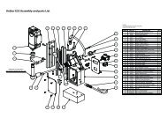
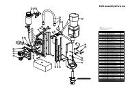
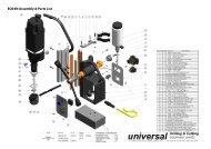
8) Exploded Diagram of the machine<br />
10
Issue 1 <strong>No</strong>vember 10<br />
9) Parts List<br />
<strong>No</strong>. Parts Name Part number Qty <strong>No</strong>. Parts Name Part number Qty<br />
1 Internal Circlip R-19 RD49000 1 40 Brush Spring RD49039 2<br />
2 Arbor Washer Ø10xØ18.5 x 0.8 RD49001 1 41 Screw M4 x 10 RD49040 2<br />
3 Coolant Seal Ø10.2xØ12.4 x 15 RD49002 1 42 Screw M4 x 12 RD49041 4<br />
4 Spring RD49003 1 43 Motor Tail Cover RD49042 1<br />
5 Lock Pin RD49004 1 44 Screw M4 x 25 RD49043 2<br />
6 Set Screw M3 x 4 RD49005 1 45 Crank Spindle RD49044 1<br />
7 Lock Pin Spring RD49006 1 46 Crank Bushing Ø28 x Ø32 x 12 RD49045 2<br />
8 Check Ball Ø8 RD49007 1 47 Thrust washer Ø25.5 x Ø40 x 2 RD49046 2<br />
9 Spindle RD49008 1 48 Ball Seat RD49047 1<br />
10 Ring Ø40xØ44 x 9 RD49009 1 49 Check Ball Ø5 RD49048 1<br />
11 Collar Pin RD49010 1 50 Crank Hub RD49049 1<br />
12 Quick-Release Collar RD49011 1 51 SpringØ0.6xØ4.1xØ5.3x4Tx8.5L RD49050 1<br />
13 Spring RD49012 1 52 Plunger RD49051 1<br />
14 Spring seat Ring RD49013 1 53 Plunger guide Ø4.1xØ10x4.5 RD49052 1<br />
15 External Circlip S-35 RD49014 1 54 Button RD49053 1<br />
16 Internal Circlip R-47 RD49015 1 55 Crank Lever RD49054 1<br />
17 Bearing 6005zz RD49016 1 56 Grip RD49055 1<br />
18 Spindle Guide RD49017 1 57 Socket Cap Screw M6 x 30 RD49056 2<br />
19 External Circlip S25 RD49018 3 58 Spring Washer M6 RD49057 3<br />
20 Gear Case RD49019 1 59 LED Lamp RD49058 1<br />
21 Bushing Ø18 x Ø23 x 4 RD49020 1 60 Flat Head Screw M4 x 6 RD49059 1<br />
22 Quill Gear M1.25 x 47T RD49021 1 61 Magnet Base 164 x 80 x 48 RD49060 2<br />
23 Bushing Ø30xØ36 x 12 RD49022 1 62 Screw M4x14 RD49061 1<br />
24 Ball Bearing 608zz RD49023 3 63 Cable Clip RD49062 1<br />
25 Bevel Gear M1.0 x 46T RD49024 1 64 Cord Armour RD49063 1<br />
26 Parallel Key M4 x 4 x 8 RD49025 1 65 Power Supply Cable RD49064 1<br />
27 Intermediate Gear M1.25 x 9T RD49026 1 66 Motor Switch RD49065 1<br />
28 Screw M5 x 25 RD49027 2 67 Magnet Switch RD49066 1<br />
29 Screw M5 x 30 RD49028 2 68 Screw M4 x 8 RD49067 8<br />
30 Gear Cover RD49029 1 69 Switch Bracket RD49068 1<br />
31 Screw M5 x 25 RD49030 4 70 Mounting Plate RD49069 1<br />
32 Bearing 6001 2RS RD49031 1 71 Overload Unit RD49070 1<br />
33 Armature M1.0 x 6T RD49032 1 72 Screw M5 x 10 RD49071 1<br />
34 Screw M5 x 60 RD49033 2 73 Socket Cap Screw M6 x 16 RD49072 1<br />
35 Stator RD49034 1 74 Screw M4 x 16 RD49073 1<br />
36 Motor Housing RD49035 1 75 Sun Washer M4 RD49074 1<br />
37 Carbon Brush 7 x 11 RD49036 2 76 Washer Ø30 x Ø38.5 RD49075 2<br />
38 Brush Holder RD49037 2 77 Seal 5cm RD49076 1<br />
39 Nut M4 RD49038 2<br />
11
Issue 1 <strong>No</strong>vember 10<br />
10) Tips for keeping your machine in correct working order.<br />
In order to ‘get the best life’ out of your Rotabroach machine always keep in good<br />
working order. A well maintained machine is a happy machine.<br />
A number of items must always be checked on Rotabroach machines.<br />
Always before starting any job make sure the machine is in good working order and that there are no damaged<br />
or loose parts. Any loose parts must be tightened.<br />
Before proceeding with any maintenance work; be certain that the power supply is<br />
disconnected.<br />
Description Every operation 1 week 1 Month<br />
Visual check of<br />
machine for damage<br />
X<br />
Operation of machine<br />
X<br />
Check brush wear<br />
X<br />
Check magnetic base<br />
X<br />
Check alignment of<br />
the machine<br />
Check grease<br />
Check Armature<br />
X<br />
X<br />
X<br />
Visually check the machine for damage.<br />
Machine must be checked before operation for any signs of damage that will affect the operation of the machine.<br />
Particular notice must be taken of the mains cable, if the machine appears to be damaged it should not be used<br />
failure to do so may cause injury or death.<br />
12
Issue 1 <strong>No</strong>vember 10<br />
Check operation of the machine.<br />
The machines operation must be checked to ensure that all components are working correctly.<br />
Machine Brushes - should be checked to make sure there is no abnormal wear present this should be<br />
checked at least once a week if used frequently. If the brush has worn more than 2/3 the original length the<br />
brushes should be changed. Failure to do so may cause damage to the machine.<br />
The carbon brushes are a normal wearing part and must be replaced when they reach their wear limit.<br />
Caution: Always replace the brushes as a pair.<br />
To replace:<br />
1. Remove the 4 screws and remove the motor tail cover.<br />
2. Using pliers rotate the brush spring out of the way and slide the old carbon brush out of the brush holder.<br />
3. Unscrew the screw to remove the brush lead. The old carbon brush may now be lifted away.<br />
4. Install a new brush. Installation is the reverse of removal.<br />
5. Replace the motor tail cover.<br />
CARBON BRUSHES<br />
Due to the brush design, if the machine comes to a stop without any reason, the brushes have to be checked. The<br />
brush design stops the machine before the carbon brushes are finished and protects the motor.<br />
Magnetic base – before every operation the magnetic base should be checked to make sure that the base is<br />
flat and there is no damage present. An uneven magnet base will cause the magnet not to hold as efficiently and<br />
may cause injury to the operator.<br />
Check machines grease.<br />
The gearbox grease should be checked once a month to ensure all moving components are covered to prevent<br />
wear. The grease should be changed at least once a year to ensure you gain the best from the machine.<br />
Check Armature of the machine.<br />
This should be checked at least 1 per month to check that there are visual signs of damage to the body or to the<br />
commutator. Some signs of wear will be seen on the commutator over a period of time this is normal as this is<br />
the part that comes in contact with the brushes but any signs of abnormal damage and the part should be<br />
replaced.<br />
13
Issue 1 <strong>No</strong>vember 10<br />
11) TROUBLE SHOOTING<br />
Magnet and motor do not function<br />
Magnet does function, the motor does not<br />
Magnet does not function, the motor does<br />
Hole cutters break quickly, holes are bigger than<br />
the hole cutter<br />
Motor running roughly and/or seizing up<br />
Motor making a rattling sound<br />
Motor humming, big sparks and motor has no<br />
force<br />
Motor does not start or fails.<br />
Guiding takes a great deal of effort<br />
Insufficient magnetic force<br />
Motor only runs at maximum rpm<br />
Frame under voltage<br />
Fuse blows when magnet switch is turned on<br />
Fuse blows when motor is started up<br />
Rotation system free stroke too long<br />
- The magnet switch is not connected to the power supply<br />
- Damaged or defective wiring<br />
- Defective fuse<br />
- Defective magnet switch<br />
- Defective Control Unit<br />
- Defective power supply<br />
- Damaged or defective wiring<br />
- Carbon brushes are stuck or worn out<br />
- Defective magnet switch<br />
- Defective On / off switch<br />
- Defective Control Unit<br />
- Defective armature and/or field<br />
- Defective magnet protective switch<br />
- Defective magnet<br />
- Defective Control Unit<br />
- Play in the guide<br />
- Bent spindle<br />
- Defective Magnet causing movement<br />
- Shaft extending from the motor is bent<br />
- Uneven work surface causing lack of magnetic adhesion.<br />
- Bent pilot<br />
- Bent spindle<br />
- Shaft extending from the motor is bent<br />
- Triangular guide not mounted straight<br />
- Dirt between spindle and triangular guide<br />
- Gear bearing (bottom of the armature) worn out<br />
- Gear(s) worn out<br />
- <strong>No</strong> grease in gear box<br />
- Armature burned<br />
- Field burned<br />
- Carbon brushes worn out<br />
- Damaged or defective wiring<br />
- Dirt in sensor of Speed Control Unit<br />
- Defective Speed Control Unit<br />
- Defective speed control or its wiring<br />
- Defective or loose magnet on top of armature<br />
- Damaged or defective brushes<br />
- Guide is set too tight<br />
- Guide is dry<br />
- Guide/gear- rack/rotation system dirty or damaged<br />
- Damaged or defective wiring<br />
- Bottom of magnet not clean and dry<br />
- Bottom of magnet not flat<br />
- Work piece is not bare metal<br />
- Work piece is not flat<br />
- Work piece is too thin less than 10mm<br />
- Defective Control Unit<br />
- Defective magnet<br />
- Defective speed switch<br />
- Damaged / defective wiring<br />
- Defective Control Unit<br />
- Damaged / defective wiring<br />
- Defective magnet<br />
- Motor seriously dirty<br />
- Damaged or defective wiring<br />
- Wrong value fuse<br />
- Defective magnet switch<br />
- Defective Control Unit<br />
- Defective magnet<br />
- Damaged or defective wiring<br />
- Wrong value fuse<br />
- Motor running roughly<br />
- Defective Armature and / or Field<br />
- Carbon brushes worn out<br />
- Defective Control Unit<br />
- Loose or defective gear-rack<br />
- Defective rotation system<br />
14
Issue 1 <strong>No</strong>vember 10<br />
WARRANTY STATEMENT<br />
Rotabroach® warrants its machines to be free from faulty materials, or workmanship under normal use for a period of 6<br />
months from initial date of purchase and 90 days for all other parts (excluding cutters), provided that the warranty<br />
registration card (or online registration) has been completed and returned to Rotabroach®, or its designated distributor<br />
within a period of (30) days from the purchase date, failure to do so will void the warranty. If the stated is adhered to<br />
Rotabroach® will repair or replace (at its option) without charge any faulty items returned.<br />
This Warranty does not cover:<br />
1. Components that are subject to natural wear and tear caused by the use in accordance with the operators instructions<br />
2. Defects in the tool caused by non-compliance with the operating instructions, improper use, abnormal environment conditions, inappropriate operating<br />
conditions overload or insufficient servicing or maintenance.<br />
3. Defects caused by using accessories, components or spare parts other than original Rotabroach® parts.<br />
4. Tools to which changes or additions have been made.<br />
5. Electrical components are subject to manufacturer’s warranty.<br />
Your online registration can be submitted on www.rotabroach.co.uk<br />
The warranty claim must be lodged within the warranty period. This requires the submission or sending of the complete tool<br />
in question with the original sales receipt which must indicate the purchase date of the product. A complaint form must also<br />
be submitted prior to the return.<br />
This can be found online at www.rotabroach.co.uk Failure to complete this form will result in the delay of your claim.<br />
All goods returned defective must be returned pre-paid to Rotabroach®, in no event shall Rotabroach® be liable for<br />
subsequent direct, or indirect loss or damage.<br />
THIS WARRANTY IS IN LIEU OF ANY OTHER WARRANTY, (EXPRESSED OR IMPLIED) INCLUDING ANY<br />
WARRANTY OF MECHANTABLITY OR FITNESS FOR A PARTICULAR PURPOSE. ROTABROACH® RESERVE THE<br />
RIGHT TO MAKE IMPROVEMENTS AND MODIFICATIONS TO DESIGN WITHOUT PRIOR NOTICE<br />
Known and Trusted Worldwide for Quality, Performance and<br />
Reliability<br />
15