DS-surge tank dual compartment 2x50 bbl-0811.pdf - FCE
DS-surge tank dual compartment 2x50 bbl-0811.pdf - FCE
DS-surge tank dual compartment 2x50 bbl-0811.pdf - FCE

You also want an ePaper? Increase the reach of your titles
YUMPU automatically turns print PDFs into web optimized ePapers that Google loves.
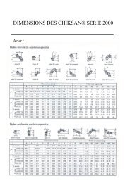
2 X 50 BBL DUAL COMPARTMENT<br />
2-PHASE SURGE TANK<br />
H2S or STANDARD SERVICE<br />
November 2008<br />
Operating data's<br />
Vessel equipment<br />
Volume 2 x 50 <strong>bbl</strong> (2 x 8 M3) Net vol. between LSL/LSH 04 x 4" Nozzle c/w pneumatic Level Switch (LSH a/b & LSL a/b)<br />
No. of <strong>compartment</strong> Two 04 x 3/4" Oil Level Gauge with graduation in <strong>bbl</strong><br />
Sour gas service Yes (as per NACE MR01-75) 02 x 2"x3" PSV (50, 100 or 150 PSI as per version)<br />
Instrument supply Gas from <strong>surge</strong> <strong>tank</strong> or rig air if sour gas 02 x Temperature Indicator 0-100°C c/w thermowell<br />
02 x Pressure Indicator (0-160 or 0-250 PSI as per version)<br />
Design data's Version 1 Version 2 Version 3 02 x Inlet jet breaker<br />
Design pressure 50 PSI 100 PSI 150 PSI 01 x Gas outlet demister<br />
Design temperature -29 to 80°C -29 to 80°C -29 to 80°C 02 x Oil outlet vortex breaker<br />
Code of construction ASME VIII Division 1 / ANSI B31-3 02 x 20" manway<br />
02 x 2" drain ball valve<br />
External connection<br />
02 x 2" blind flange (vessel drain in horizontal position)<br />
Oil inlet<br />
3" Weco fig. 602 F<br />
Oil / Drain outlet 3" Weco fig. 602 M Inlet line equipment<br />
Gas outlet 3" Weco fig. 602 M 01 x 3" by-pass ball valve to oil outlet<br />
Relief gas outlet 4" Weco fig. 602 M 02 x 3" inlet ball valve<br />
Air instrument supply 1/2" Quick coupling 01 x Pressure Indicator (0-160 or 0-250 PSI as per version)<br />
LSL output signal (a & b) 1/4" Quick coupling<br />
LSH output signal (a & b) 1/4" Quick coupling<br />
Oil outlet equipment<br />
02 x 3" ball valve<br />
Dimensions & Weight (horizontal position)<br />
Length 7450 mm (293.3 ") Gas outlet equipment<br />
Width 2500 mm (98.4 ") 01 x Pressure Controller (0-60, 0-200 PSI as per version)<br />
Height 2750 mm (108.3 ") 01 x 3" PCV with 6/30 PSI actuator (Cv Max 136)<br />
Weight (empty) 13200 Kg / 13800 Kg / 14450 Kg 01 x 3" ball valve<br />
29140 lbs / 30460 lbs / 31900 lbs<br />
Miscellaneous equipment<br />
Removable crash frame<br />
35 PSI air/gas instrument system c/w scrubber, regulators & 3/8" tubing<br />
02 x fixed ladder on rear side (vertical position)<br />
MAIN COMPONENT BRAND<br />
QUALITY<br />
Gas PCV & PC EMERSON FISHER 100% radiography on vessel & 20% on process pipework<br />
LSH & LSL FMC-INVALCO 10% hardness test<br />
Ball Valves AOP 100% MPI on lifting lugs and primary structure<br />
PSV TYCO or equivalent Hydrostatic Pressure Test as per code & Leak Test<br />
Option Gas Flow Orifice Fitting DANIEL equivalent / CANALTA 100% traceability on vessel and pipes<br />
Option Gas Flow Recorder BARTON Instrument calibration reports & certificate of compliance<br />
Option Gas Turbine Meter FMC-INVALCO Quality and Operating & Maintenance books<br />
Option Oil Automatic Flow Valve FMC-INVALCO<br />
FIXED OPTIONS / ADDERS<br />
INTERCHANGEABLE OPTIONS / ADDERS<br />
A-01 Standard service equipment<br />
B-01 LSH/LSH pneumatic horn c/w check valves<br />
A-02 Low temperature service - 40°C<br />
B-02 LSHH & LSLL (to be specified pneumatic or electric signal)<br />
A-03 04 x 4" Nozzle c/w blind flange (for LSHH & LSLL option) B-03 Gas metering orifice fitting to gas line size c/w upstream<br />
A-04 3" Gas outlet line c/w 2" PCV, 2" ball valve and 3" Weco end<br />
orifice plates and 3-pen recorder (DP cell range to be specified)<br />
A-05 Automatic pneumatic control system c/w <strong>surge</strong> pulse counter, B-04 Gas turbine meter to gas line size c/w pipework kit and FQT.<br />
automatic inlet and oil outlet flow valves<br />
B-05 Set of necessary transmitters for D.A.S. (to be specified)<br />
A-06 Internal coating<br />
B-06 Set of cables and junction boxes for D.A.S. (to be specified)<br />
A-07 EN-12079 / DNV 2.7.1 crash frame / skid<br />
B-07 1/4" Sampling point with quick connect on gas and oil outlets<br />
A-08 ASME U-stamp<br />
B-08 Other interchangeable component brand / Added instruments<br />
A-09 Full material traceability on wetted parts<br />
A-10 Load Test on skid and frame<br />
A-11 Specific requirement (Requires <strong>FCE</strong> engineering approval)<br />
Fluid Control Europe (<strong>FCE</strong>)<br />
786 rue George Sand - ZI Molina la Chazotte - 42350 La Talaudière (France)<br />
Tel. +33 (0)4 77 48 13 13 - Fax +33 (0)4 77 33 01 30 - e-mail fce@fce.fr - web site www.fce.fr
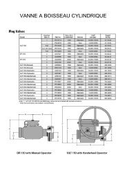
2 X 50 BBL DUAL COMPARTMENT<br />
2-PHASE SURGE TANK<br />
H2S or STANDARD SERVICE<br />
November 2008<br />
2750<br />
2500<br />
OPTIONAL<br />
LSHH<br />
LSH<br />
OD 2100<br />
OIL / DRAIN OUTLET<br />
Weco 3'' 602 male<br />
OIL INLET<br />
Weco 3'' 602 femelle<br />
RELIEF GAS OUTLET<br />
Weco 4'' 602 male<br />
GAS OUTLET<br />
Weco 3'' 602 male<br />
7450<br />
LOCAL<br />
CONTROL<br />
PANEL<br />
T I<br />
P I<br />
T I<br />
P I<br />
LSL<br />
LSLL<br />
OPTIONAL<br />
Fluid Control Europe (<strong>FCE</strong>)<br />
786 rue George Sand - ZI Molina la Chazotte - 42350 La Talaudière (France)<br />
Tel. +33 (0)4 77 48 13 13 - Fax +33 (0)4 77 33 01 30 - e-mail fce@fce.fr - web site www.fce.fr