Wurlitzer 1015 45 RPM Jukebox Manual - BMI Gaming
Wurlitzer 1015 45 RPM Jukebox Manual - BMI Gaming
Wurlitzer 1015 45 RPM Jukebox Manual - BMI Gaming

Create successful ePaper yourself
Turn your PDF publications into a flip-book with our unique Google optimized e-Paper software.
To Purchase This Item, Visit <strong>BMI</strong> <strong>Gaming</strong> | www.bmigaming.com | (800) 746-2255 | +1.561.391.7200<br />
21 GB<br />
R<br />
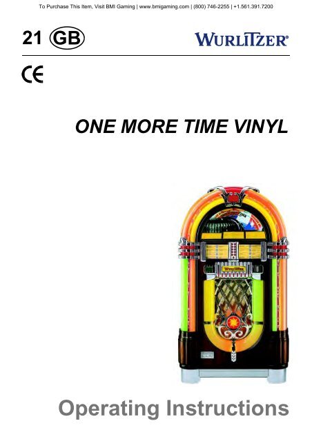
ONE MORE TIME VINYL<br />
Operating Instructions
To Purchase This Item, Visit <strong>BMI</strong> <strong>Gaming</strong> | www.bmigaming.com | (800) 746-2255 | +1.561.391.7200<br />
1 Technical details OMT VINYL . . . . . . . . . . . . . . . . . . . . . . . . . . . . . . . . . . . . . . . . 3<br />
1.1 Features . . . . . . . . . . . . . . . . . . . . . . . . . . . . . . . . . . . . . . . . . . . . . . . . . . . . . . . . . . . . . . . . . . . . . . . . . 3<br />
1.2 Power supply . . . . . . . . . . . . . . . . . . . . . . . . . . . . . . . . . . . . . . . . . . . . . . . . . . . . . . . . . . . . . . . . . . . . . 3<br />
1.3 Dimensions: . . . . . . . . . . . . . . . . . . . . . . . . . . . . . . . . . . . . . . . . . . . . . . . . . . . . . . . . . . . . . . . . . . . . . . 3<br />
1.4 Optional . . . . . . . . . . . . . . . . . . . . . . . . . . . . . . . . . . . . . . . . . . . . . . . . . . . . . . . . . . . . . . . . . . . . . . . . . 3<br />
2 Set up to play . . . . . . . . . . . . . . . . . . . . . . . . . . . . . . . . . . . . . . . . . . . . . . . . . . . . . 4<br />
3 Component functions and adjustment . . . . . . . . . . . . . . . . . . . . . . . . . . . . . . . . . 4<br />
3.1 Selection & Credit Computer (S&CC) . . . . . . . . . . . . . . . . . . . . . . . . . . . . . . . . . . . . . . . . . . . . . . . . . 4<br />
3.2 Service programs . . . . . . . . . . . . . . . . . . . . . . . . . . . . . . . . . . . . . . . . . . . . . . . . . . . . . . . . . . . . . . . . . 5<br />
3.2.1 How to call up service program . . . . . . . . . . . . . . . . . . . . . . . . . . . . . . . . . . . . . . . . . . . . . . . . . . . . . . . . 5<br />
3.2.2 How to leave the service program . . . . . . . . . . . . . . . . . . . . . . . . . . . . . . . . . . . . . . . . . . . . . . . . . . . . . . 6<br />
3.2.3 Memory ON/OFF . . . . . . . . . . . . . . . . . . . . . . . . . . . . . . . . . . . . . . . . . . . . . . . . . . . . . . . . . . . . . . . . . . . 6<br />
3.3 Free play . . . . . . . . . . . . . . . . . . . . . . . . . . . . . . . . . . . . . . . . . . . . . . . . . . . . . . . . . . . . . . . . . . . . . . . . . 6<br />
3.4 Playstimulator / continuous play . . . . . . . . . . . . . . . . . . . . . . . . . . . . . . . . . . . . . . . . . . . . . . . . . . . . . 7<br />
3.5 Coin and credit programming . . . . . . . . . . . . . . . . . . . . . . . . . . . . . . . . . . . . . . . . . . . . . . . . . . . . . . . 8<br />
4 Device description of the amplifier K99 . . . . . . . . . . . . . . . . . . . . . . . . . . . . . . . . 9<br />
5 Technical data K99 . . . . . . . . . . . . . . . . . . . . . . . . . . . . . . . . . . . . . . . . . . . . . . . . . 9<br />
6 Verification of power voltage. . . . . . . . . . . . . . . . . . . . . . . . . . . . . . . . . . . . . . . . 10<br />
7 Position of fuses and plug connectors on the K99 . . . . . . . . . . . . . . . . . . . . . . 11<br />
8 The first power ON . . . . . . . . . . . . . . . . . . . . . . . . . . . . . . . . . . . . . . . . . . . . . . . . 12<br />
9 Volume control . . . . . . . . . . . . . . . . . . . . . . . . . . . . . . . . . . . . . . . . . . . . . . . . . . . 12<br />
10 The infrared remote control . . . . . . . . . . . . . . . . . . . . . . . . . . . . . . . . . . . . . . . . . 13<br />
11 Treble and bass control . . . . . . . . . . . . . . . . . . . . . . . . . . . . . . . . . . . . . . . . . . . . 14<br />
12 Automatic volume correction . . . . . . . . . . . . . . . . . . . . . . . . . . . . . . . . . . . . . . . 14<br />
13 Background Music - volume attenuation . . . . . . . . . . . . . . . . . . . . . . . . . . . . . . 14<br />
14 External speaker connection . . . . . . . . . . . . . . . . . . . . . . . . . . . . . . . . . . . . . . . . 15<br />
15 External amplifier connection . . . . . . . . . . . . . . . . . . . . . . . . . . . . . . . . . . . . . . . 16<br />
16 Disabling the internal mute circuit . . . . . . . . . . . . . . . . . . . . . . . . . . . . . . . . . . . 17<br />
17 Input selector . . . . . . . . . . . . . . . . . . . . . . . . . . . . . . . . . . . . . . . . . . . . . . . . . . . . 17<br />
18 Trouble shooting chart. . . . . . . . . . . . . . . . . . . . . . . . . . . . . . . . . . . . . . . . . . . . . 18<br />
18.1 Failures of the illumination, lamps and power system generally . . . . . . . . . . . . . . . . . . . . . . . . . . 18<br />
18.2 Fuses of the power supply - which one controls what circuit . . . . . . . . . . . . . . . . . . . . . . . . . . . . 19<br />
18.3 Faults with the coin and credit system . . . . . . . . . . . . . . . . . . . . . . . . . . . . . . . . . . . . . . . . . . . . . . . 20<br />
18.4 Faults with the selection system (Credit system is working) . . . . . . . . . . . . . . . . . . . . . . . . . . . . . 21<br />
18.5 Repetitive play of records, selected or non-selected ones . . . . . . . . . . . . . . . . . . . . . . . . . . . . . . . 22<br />
18.6 Failures of the record changer after properly completed selection . . . . . . . . . . . . . . . . . . . . . . . . 22<br />
18.7 Failures with the tone arm or the tone system . . . . . . . . . . . . . . . . . . . . . . . . . . . . . . . . . . . . . . . . . 24<br />
OMT VINYL – edition: 13.08.2007<br />
1
To Purchase This Item, Visit <strong>BMI</strong> <strong>Gaming</strong> | www.bmigaming.com | (800) 746-2255 | +1.561.391.7200<br />
18.8 Record not properly returned to carrier . . . . . . . . . . . . . . . . . . . . . . . . . . . . . . . . . . . . . . . . . . . . . . 24<br />
18.9 Notes . . . . . . . . . . . . . . . . . . . . . . . . . . . . . . . . . . . . . . . . . . . . . . . . . . . . . . . . . . . . . . . . . . . . . . . . . . 25<br />
18.9.1 Note 1 . . . . . . . . . . . . . . . . . . . . . . . . . . . . . . . . . . . . . . . . . . . . . . . . . . . . . . . . . . . . . . . . . . . . . . . . . . 25<br />
18.9.2 Note 2 . . . . . . . . . . . . . . . . . . . . . . . . . . . . . . . . . . . . . . . . . . . . . . . . . . . . . . . . . . . . . . . . . . . . . . . . . . 25<br />
18.9.3 Note 3 A . . . . . . . . . . . . . . . . . . . . . . . . . . . . . . . . . . . . . . . . . . . . . . . . . . . . . . . . . . . . . . . . . . . . . . . . 25<br />
18.9.4 Note 3 B . . . . . . . . . . . . . . . . . . . . . . . . . . . . . . . . . . . . . . . . . . . . . . . . . . . . . . . . . . . . . . . . . . . . . . . . 26<br />
18.9.5 Note 3 C . . . . . . . . . . . . . . . . . . . . . . . . . . . . . . . . . . . . . . . . . . . . . . . . . . . . . . . . . . . . . . . . . . . . . . . . 26<br />
18.9.6 Note 4 . . . . . . . . . . . . . . . . . . . . . . . . . . . . . . . . . . . . . . . . . . . . . . . . . . . . . . . . . . . . . . . . . . . . . . . . . . 26<br />
18.9.7 Note 5 . . . . . . . . . . . . . . . . . . . . . . . . . . . . . . . . . . . . . . . . . . . . . . . . . . . . . . . . . . . . . . . . . . . . . . . . . . 26<br />
18.9.8 Note 6 . . . . . . . . . . . . . . . . . . . . . . . . . . . . . . . . . . . . . . . . . . . . . . . . . . . . . . . . . . . . . . . . . . . . . . . . . . 26<br />
18.9.9 Note 7 . . . . . . . . . . . . . . . . . . . . . . . . . . . . . . . . . . . . . . . . . . . . . . . . . . . . . . . . . . . . . . . . . . . . . . . . . . 27<br />
18.9.10 Note 8 . . . . . . . . . . . . . . . . . . . . . . . . . . . . . . . . . . . . . . . . . . . . . . . . . . . . . . . . . . . . . . . . . . . . . . . . . . 27<br />
18.9.11 Note 9 . . . . . . . . . . . . . . . . . . . . . . . . . . . . . . . . . . . . . . . . . . . . . . . . . . . . . . . . . . . . . . . . . . . . . . . . . . 27<br />
18.9.12 Note 10 . . . . . . . . . . . . . . . . . . . . . . . . . . . . . . . . . . . . . . . . . . . . . . . . . . . . . . . . . . . . . . . . . . . . . . . . . 27<br />
19 Connection diagram . . . . . . . . . . . . . . . . . . . . . . . . . . . . . . . . . . . . . . . . . . . . . . . 28<br />
20 Circuit diagram OMT VINYL chassis . . . . . . . . . . . . . . . . . . . . . . . . . . . . . . . . . . 29<br />
21 Wiring diagram K99 - power supply . . . . . . . . . . . . . . . . . . . . . . . . . . . . . . . . . . 30<br />
22 Wiring diagram K99 - power amp. . . . . . . . . . . . . . . . . . . . . . . . . . . . . . . . . . . . . 31<br />
23 Wiring diagram K99 - pre amp . . . . . . . . . . . . . . . . . . . . . . . . . . . . . . . . . . . . . . . 32<br />
24 Wiring diagram K99 - sound controler . . . . . . . . . . . . . . . . . . . . . . . . . . . . . . . . 33<br />
25 Wiring diagram K99 - port A . . . . . . . . . . . . . . . . . . . . . . . . . . . . . . . . . . . . . . . . . 34<br />
26 Wiring diagram K99 - mute . . . . . . . . . . . . . . . . . . . . . . . . . . . . . . . . . . . . . . . . . . 35<br />
27 Wiring diagram K99 - power supply Euro 230V . . . . . . . . . . . . . . . . . . . . . . . . . 36<br />
28 Connection diagram IR remote control/amplifier K99 . . . . . . . . . . . . . . . . . . . . 38<br />
2<br />
OMT VINYL – edition: 13.08.2007
To Purchase This Item, Visit <strong>BMI</strong> <strong>Gaming</strong> | www.bmigaming.com | (800) 746-2255 | +1.561.391.7200<br />
Features<br />
1 Technical details OMT VINYL<br />
1.1 Features<br />
! Stereo amplifier with automatic level control and electronic overload protection, power 2 x 55w<br />
RMS<br />
! 3 way stereo loudspeaker system with 6 speakers<br />
! 100 selections (50 records) played by a high quality Tonar Magnetic System<br />
! Microprocessor controlling all functions including credit and bonus steps as well as record plays<br />
and automatic memory of the top tunes<br />
! Playstimulator playing a record in intervals between 1 and 98 minutes automatically<br />
! An LED display presents playing record or credit available<br />
! Integrated volume control which can also be used as wired remote control<br />
! Connections for additional amplifier, external loudspeakers, microphone kit and output<br />
transformer<br />
1.2 Power supply<br />
100 - 240v, 50/60cps<br />
1.3 Dimensions:<br />
Height<br />
Width<br />
Depth<br />
Weight<br />
1520mm / 60.0inch<br />
815mm / 32.0inch<br />
640mm / 25.25inch<br />
157kg / 346lbs<br />
1.4 Optional<br />
! Infrared remote control with selection buttons<br />
! Output transformer<br />
! Microphone kit<br />
! External speakers: Model LS 121<br />
2 way speaker system, floor standing or wall mounting, cabinet with wooden pattern or black high<br />
polish surface.<br />
Dimensions:<br />
Height 520mm / 20.5inch<br />
Width 320mm / 12.6inch<br />
Depth 250mm / 9.8inch<br />
Musical power 120w, 8ohms<br />
OMT VINYL – edition: 13.08.2007<br />
3
To Purchase This Item, Visit <strong>BMI</strong> <strong>Gaming</strong> | www.bmigaming.com | (800) 746-2255 | +1.561.391.7200<br />
Selection & Credit Computer (S&CC)<br />
2 Set up to play<br />
The ONE MORE TIME VINYL is delivered ready to play. There are several tasks to perform in order<br />
to ensure proper operation and best sound.<br />
1. Open the jukebox. Apply slightly pressure against the door while turning the key. The lock is<br />
spring loaded so the slight pressure against the door allows the key to turn easily.<br />
2. Remove the shipping bolts (M8x70) from the mechanism platform. There are two, one in the<br />
rear right corner near the base of the tone arm, the other one in the front left corner near the<br />
record carrier.<br />
These bolts secure the platform during transport. Remove these bolts completely.<br />
3. Release the tie-down tone arm strap located at the base of the tone arm. This strap secures the<br />
tone arm during transport. Check the cartridge and needle to insure proper position in the tone<br />
arm.<br />
4. Place the records in the record carrier and title strips into the corresponding numerical slots in<br />
the title strip holder. The holder can be removed completely from the machine to allow better<br />
access by pushing the two locking springs left and right side slightly inwards.<br />
To turn the record carrier, operate the lever marked ’rotate carrier’. The record carrier can be<br />
turned in steps to achieve the best position for loading.<br />
To step up credit, please use the credit button on the coin acceptor interface (Europe version) or<br />
the credit button on the coin channel (US version).<br />
" You should now be ready to enter a selection.<br />
NOTE: Save the shipping guards and the tone arm strap. You will need them in case you decide to<br />
move the jukebox to another location. Records should be taken out for transportation.<br />
ATTENTION! Some parts of the electrical circuitary are connected to the power line (power<br />
transformer, fluorescent tube, ballast and accociated wiring).<br />
Never attempt any intervention to these parts unless qualified.<br />
3 Component functions and adjustment<br />
3.1 Selection & Credit Computer (S&CC)<br />
The Selection and Credit Computer is the brain of the One More Time Vinyl. There are several<br />
optional programs and programming features which can be very useful.<br />
! Service Program<br />
This program allows to retrieve various information as well as concluding certain service checks<br />
on the mechanism. All programs are communicated to the S&CC by means of the selection<br />
buttons.<br />
! Free play<br />
This allows free selection of multiple titles.<br />
! Playstimulator<br />
The playstimulator plays a record automatically in intervals of 1 to 98 minutes.<br />
4<br />
OMT VINYL – edition: 13.08.2007
ST1 ST2 ST3<br />
To Purchase This Item, Visit <strong>BMI</strong> <strong>Gaming</strong> | www.bmigaming.com | (800) 746-2255 | +1.561.391.7200<br />
Service programs<br />
3.2 Service programs<br />
3.2.1 How to call up service program<br />
1 2<br />
1. Set slide switch ’SERVICE’ (1) to ’ON’.<br />
2. Press ’LT’ button (2) once.<br />
K<br />
Service ON<br />
OFF<br />
Z<br />
T.T.<br />
+2<br />
+3<br />
GP +<br />
6<br />
Korb<br />
Location<br />
F<br />
6<br />
5<br />
4<br />
7<br />
6<br />
5<br />
4<br />
6<br />
5<br />
4<br />
3<br />
2<br />
3 3<br />
2 2 1 1 1<br />
0 0 0 0 0<br />
GP BS B4 B3 B2 B1<br />
6<br />
5<br />
4<br />
3<br />
2<br />
6<br />
5<br />
4<br />
3<br />
2<br />
M<br />
LT<br />
1<br />
2<br />
4<br />
5<br />
T1<br />
10<br />
+B<br />
20T<br />
Selection &<br />
Credit Computer<br />
100 - 160 - 200<br />
M3 M6 M C<br />
ACHTUNG: MEMORY-Stecker von OFF<br />
auf ON umstecken, wenn<br />
Top Tunes, Popularitätszähler<br />
oder Kassenzähler arbeiten soll.<br />
ATTENTION: Move MEMORY Plug from OFF<br />
to ON if Top tunes, Pop Meter or<br />
Cash Box Content Registration<br />
is required.<br />
A TTENTION:<br />
Placer la prise MEMORY en<br />
position ON de la position OFF<br />
si le Top Tunes, le compteur de<br />
popularité et le contenu de la<br />
caisse sont demandés.<br />
0047971<br />
ON<br />
Memory<br />
OFF<br />
Button 0 - least popular titles (flops)<br />
Pressing button 0 once indicates the least<br />
popular record. Pressing button 0 again<br />
shows the record with second lowest number<br />
of plays. Press button 0 again shows the<br />
third lowest etc..<br />
Press button ’R’ (RESET) to terminate the<br />
’flop’ call.<br />
Button 1 - Top Tunes<br />
Shows the record which was played most frequently followed by the number of plays (Max. 99). If<br />
one record was played more often than 99 times, the counter remains in this position. Pressing<br />
button 1 again shows the second popular record, etc.<br />
Press button ’R’ RESET to terminate the ’Top Tune’ call.<br />
Button 2 - cash box contents<br />
Shows the cash box contents in basic units; basic units being the value of the lowest coin, resp. coin<br />
value of coin output 1 on the S&CC.<br />
Example (lowest coin 25ct): display readout: 0 4 5 = <strong>45</strong> x 25ct = $ 11.25<br />
Press button ’R’ RESET to terminate the ’cash box contents’ call.<br />
Button 3 - clear memory<br />
Press and hold down button 3, then press button ’R’ RESET. All counters are reset to zero.<br />
Button 4 - display check and program number version<br />
When you press button 4 the digital display automatically indicates the number 8 on all three digits.<br />
Successivly ’Record Playing’, ’Hit of the House’, ’Error’ and ’Credit’ will light and the program version<br />
number will appear, e.g. 7.01 or higher.<br />
Button 5 - Playstimulator<br />
The playstimulator is playing a random record automatically after a programmed time period. It is<br />
programmable between 1 and 98 minutes. For programming please refer to chapter 3.4, on page 7.<br />
OMT VINYL – edition: 13.08.2007<br />
5
ST1 ST2 ST3<br />
Free play<br />
To Purchase This Item, Visit <strong>BMI</strong> <strong>Gaming</strong> | www.bmigaming.com | (800) 746-2255 | +1.561.391.7200<br />
Button 6 - A-side solenoid<br />
When you press button 6 the display shows 6 - 1, relay M6 of the S&CC and the A-side solenoid<br />
should be activated while the display shows 6 - 2.<br />
Button 7 - check of gear box motor<br />
When you press button 7 relay M should be activated and the changer plays the B-side of the record.<br />
Display shows 7 - 4.<br />
After the record has been played, it will be returned into the carrier.<br />
Button 8 - check of record carrier<br />
When you press button 8 relay M3 is activated and the record carrier turns as long as button 8 is<br />
pressed. The gripper arm must be in rest position. The display shows 8 - 0.<br />
Button 9 - gripper arm position<br />
Press button 9, test of the gripper arm position. Display shows 9 - 0 if the gripper arm is in rest<br />
position, 9 - 1 if the gripper arm is in play position.<br />
3.2.2 How to leave the service program<br />
1. Set slide switch ’SERVICE’ to ’OFF’.<br />
1. Press ’LT’ button. The record carrier turns to position 101.<br />
3.2.3 Memory ON/OFF<br />
ATTENTION! Statistic read outs<br />
(service programs 0 - 2) are only<br />
valid if the internal memory<br />
battery is connected to Memory<br />
ON (plug on upper pin) as<br />
shown.<br />
With Memory OFF (plug on lower<br />
pin) counters are reset when the<br />
jukebox is switched off.<br />
K<br />
Service ON<br />
OFF<br />
Z<br />
Selection &<br />
Credit Computer<br />
100 - 160 - 200<br />
M3 M6 M C<br />
T.T.<br />
+2<br />
+3<br />
GP +<br />
6<br />
Korb<br />
Location<br />
F<br />
6<br />
5<br />
4<br />
7<br />
6<br />
5<br />
4<br />
6<br />
5<br />
4<br />
3<br />
2<br />
3 3<br />
2 2 1 1 1<br />
0 0 0 0 0<br />
GP BS B4 B3 B2 B1<br />
6<br />
5<br />
4<br />
3<br />
2<br />
6<br />
5<br />
4<br />
3<br />
2<br />
0047971<br />
M<br />
LT<br />
ACHTUNG: MEMORY-Stecker von OFF<br />
auf ON umstecken, wenn<br />
Top Tunes, Popularitätszähler<br />
oder Kassenzähler arbeiten soll.<br />
ATTENTION: Move MEMORY Plug from OFF<br />
to ON if Top tunes, Pop Meter or<br />
Cash Box Content Registration<br />
is required.<br />
A TTENTION:<br />
Placer la prise MEMORY en<br />
position ON de la position OFF<br />
si le Top Tunes, le compteur de<br />
popularité et le contenu de la<br />
caisse sont demandés.<br />
1<br />
2<br />
4<br />
5<br />
T1<br />
10<br />
+B<br />
ON<br />
Memory<br />
OFF<br />
20T<br />
3.3 Free play<br />
Connect jumper wire on ’GP’ between<br />
0 and F on the S&CC. Press ’LT’<br />
button.<br />
Free play now allows free selections.<br />
ON<br />
OFF<br />
T.T.<br />
+2<br />
+3<br />
GP +<br />
6<br />
Korb<br />
Location<br />
F 7 6 6 6<br />
6 6 5 5 5<br />
5 5 4 4 4<br />
4 4 3 3 3<br />
3 3 2 2 2<br />
2 2 1 1 1<br />
0 0 0 0 0<br />
GP BS B4 B3 B2 B1<br />
M<br />
LT<br />
6<br />
OMT VINYL – edition: 13.08.2007
ST1 ST2 ST3<br />
To Purchase This Item, Visit <strong>BMI</strong> <strong>Gaming</strong> | www.bmigaming.com | (800) 746-2255 | +1.561.391.7200<br />
Playstimulator / continuous play<br />
3.4 Playstimulator / continuous play<br />
The playstimulator may be programmed to random selection of a title in periods of 1 to 98 minutes.<br />
(Factory preset is 99 for continuous play). Therefore:<br />
1. Call up service program (slide switch SERVICE in position ON, press ’LT’ button once).<br />
2. Press button 5.<br />
3. Press button 9, display shows 9 _ _.<br />
4. Enter number of minutes required for the interval between play<br />
# 01 = 1 minute<br />
# 02 = 2 minutes etc.<br />
# 00 = playstimulator is switched OFF<br />
# 99 = continuous play<br />
5. Press button ’R’ RESET.<br />
6. Set slide switch SERVICE to position OFF.<br />
7. Press ’LT’ button.<br />
NOTE: If the jukebox is equipped with<br />
a continuous play switch, you only<br />
have to set the slide switch to position<br />
ON to activate the playstimulator/<br />
continuous play.<br />
K<br />
Service ON<br />
OFF<br />
Z<br />
T.T.<br />
+2<br />
+3<br />
GP +<br />
6<br />
Korb<br />
Location<br />
F<br />
6<br />
5<br />
4<br />
7<br />
6<br />
5<br />
4<br />
6<br />
5<br />
4<br />
3<br />
2<br />
3 3<br />
2 2 1 1 1<br />
0 0 0 0 0<br />
GP BS B4 B3 B2 B1<br />
6<br />
5<br />
4<br />
3<br />
2<br />
6<br />
5<br />
4<br />
3<br />
2<br />
M<br />
LT<br />
1<br />
2<br />
4<br />
5<br />
T1<br />
10<br />
+B<br />
20T<br />
Continuous<br />
Selection &<br />
Credit Computer<br />
100 - 160 - 200<br />
M3 M6 M C<br />
ACHTUNG: MEMORY-Stecker von OFF<br />
auf ON umstecken, wenn<br />
Top Tunes, Popularitätszähler<br />
oder Kassenzähler arbeiten soll.<br />
ATTENTION: Move MEMORY Plug from OFF<br />
to ON if Top tunes, Pop Meter or<br />
Cash Box Content Registration<br />
is required.<br />
A TTENTION:<br />
Placer la prise MEMORY en<br />
position ON de la position OFF<br />
si le Top Tunes, le compteur de<br />
popularité et le contenu de la<br />
caisse sont demandés.<br />
0047971<br />
ON<br />
Memory<br />
OFF<br />
Play<br />
on<br />
off<br />
OMT VINYL – edition: 13.08.2007<br />
7
To Purchase This Item, Visit <strong>BMI</strong> <strong>Gaming</strong> | www.bmigaming.com | (800) 746-2255 | +1.561.391.7200<br />
Coin and credit programming<br />
3.5 Coin and credit programming<br />
The price per play is set by jumper wires on the S&CC as shown in the examples. After having<br />
changed wire links press ’LT’ button to confirm new settings.<br />
US (example)<br />
25cts $ 1.00<br />
PRICE OF SELECTION<br />
1 play for 50 cts<br />
3 plays for $ 1.00<br />
21 plays for $ 5.00<br />
Select 222 for 8 Top Ten<br />
TT<br />
+2<br />
+3<br />
GP+6<br />
Korb<br />
Location<br />
:<br />
:<br />
:<br />
:<br />
:<br />
:<br />
:<br />
F<br />
6<br />
5<br />
4<br />
3<br />
2<br />
:<br />
:<br />
:<br />
:<br />
:<br />
7 : : : : :<br />
1<br />
6 6 6<br />
6 : : : : :<br />
2<br />
5 5 5<br />
5 : : 4 : 4 : 4 :<br />
4<br />
4 : : 3 : 3 : 3 :<br />
5<br />
3 : : 2 : 2 : 2 :<br />
T1<br />
LT<br />
2 : : 1 : 1 : 1 :<br />
10<br />
: : 0 : 0 : 0 :<br />
20<br />
:<br />
0 : 0<br />
GP BS B4 B3 B2 B1<br />
^<br />
+B<br />
0,25 blue<br />
1 $ grey<br />
orange<br />
yellow<br />
white<br />
brown<br />
Coinco<br />
mech.<br />
Europe (example)<br />
0,5 1,- 2,-<br />
T.T. : F : 7 : : : : :<br />
1 0,5 red.<br />
6 6 6<br />
+2 : 6 : 6 : : : : :<br />
2 1,0 brown<br />
5 5 5<br />
+3 : 5 : 5 : : : : :<br />
4 2,0 white<br />
4 4 4<br />
GP : 4 : 4 : : : : :<br />
5<br />
2 plays - 0,5<br />
3 3 3<br />
: : : : : : :<br />
+6<br />
3 3 2 2 2<br />
T1 grey<br />
LT<br />
5 plays - 1,-<br />
: 2 : 2 : : 1 : 1 : 1 :<br />
10<br />
: : : : 0 : 0 : 0 :<br />
20<br />
11 plays - 2,-<br />
Korb<br />
Location<br />
0 0<br />
GP BS B4 B3 B2 B1<br />
T<br />
+B<br />
green<br />
violet<br />
NRI<br />
Credit button<br />
on interface<br />
G13<br />
8<br />
OMT VINYL – edition: 13.08.2007
To Purchase This Item, Visit <strong>BMI</strong> <strong>Gaming</strong> | www.bmigaming.com | (800) 746-2255 | +1.561.391.7200<br />
Coin and credit programming<br />
4 Device description of the amplifier K99<br />
The amplifier K99 is optimised for universal use in Deutsche <strong>Wurlitzer</strong> GmbH jukeboxes. Great<br />
importance had been attached for an easy handling and stand alone function without the S&CC unit.<br />
The output power is designed for the standard used internal speakers of Deutsche <strong>Wurlitzer</strong> GmbH<br />
jukeboxes.<br />
DETAILS:<br />
Standard equipment:<br />
! Hybrid power stage technology, short circuit and over temperature protected<br />
! 2 inputs (stereo): CD and tape<br />
! 1 mono input for optional microphone kit<br />
! Volume control with 2 pots onboard<br />
! Volume control possible with pots and / or IR at the same time. The pot used at last determines<br />
the volume.<br />
! The wired remote box is accessible from the machine rear wall with 2 volume control pots, cancel<br />
and mute button (mute with toggle function).<br />
! Bass and treble control with pots<br />
! BGM volume reduction, controllable with pot<br />
! Automatic volume correction (AVC), switchable<br />
! 2 channel operation switchable, RH = internal speakers, LH = external speakers<br />
! Status display with 7segment display<br />
! Independent controllable RCA output to connect external amplifiers<br />
! For use with the old and the new changer mechanism.<br />
!<br />
Optional:<br />
! Remote control with large distance range. Functions: track selection / volume chan. 1 / volume<br />
chan. 2 / mute (toggle) / cancel<br />
! 70v output transformer<br />
! Microphone kit<br />
5 Technical data K99<br />
General<br />
USA / Canada<br />
Supply 100v - 240v 117v<br />
Mains frequency 50cps - 60cps 60cps<br />
Input voltage CD typ. 1.2v typ. 1.2v<br />
Input voltage tape 300mv 300mv<br />
Output voltage pre amplifier
To Purchase This Item, Visit <strong>BMI</strong> <strong>Gaming</strong> | www.bmigaming.com | (800) 746-2255 | +1.561.391.7200<br />
Coin and credit programming<br />
6 Verification of power voltage<br />
The voltage settings are marked on<br />
the cover plate of the mains<br />
transformer. Machines for USA are<br />
set to 117v. They have a special<br />
transformer according to UL standard<br />
which is not adjustable. <strong>Jukebox</strong>es<br />
“UNI-Pack” are shipped with 230v<br />
setting. Mains voltage is indicated on<br />
the label of the transformer cover. The<br />
mains fuse (T3.15A/230v F6A/117v)<br />
is located on the left bottom side inbetween<br />
the three terminals for the bill<br />
acceptor, the external mains switch<br />
and the fluorescent lamps.<br />
Loosen the four screws to remove the<br />
cover plate (small arrows) to get<br />
access to the mains transformer.<br />
Achtung<br />
Vor A nahme er appe en Netzstecker<br />
ziehen<br />
arning<br />
Shock hazar o not open<br />
Netzsicherung<br />
Scheinannehmer<br />
210-240V - T 4A<br />
Mains Fuse<br />
Billacceptor<br />
100-117V - F 6A<br />
Netzsicherung/<br />
Mains Fuse<br />
210-240V - T3,15A<br />
100-117V - F6A<br />
Externer Hauptschalter<br />
External Mains switch<br />
Leuchtstofflampen<br />
Fluorescent Lamps<br />
230V / 117V<br />
240<br />
230<br />
220<br />
210<br />
117<br />
100<br />
Netzspannung<br />
50/60 Hz<br />
Mains Voltage<br />
50/60 cps<br />
ur Beachtung Nur Sicherungen mit<br />
gleicher r e un gleichem ert<br />
erwen en, um Schä en zu ermei en<br />
aution To re uce the risk of fire<br />
replace onl with same t p an rating fuses<br />
Verstärker<br />
Amplifier<br />
ATTENTION! Always remove power plug before opening transformer cover plate. Never<br />
attempt any intervention to these parts unless qualified!<br />
The position of the two plug connectors on the transformer terminals 1 to 9 (primary side) indicates<br />
the current voltage setting. The following combinations are possible:<br />
240v = 1 - 9<br />
230v = 1 - 8<br />
220v = 2 - 9<br />
210v = 2 - 8<br />
117v = 1 - 6<br />
100v = 2 - 6<br />
Notice that these settings cannot be<br />
made on machines produced<br />
according to UL standard (US<br />
version).<br />
NOTE: Never connect the fluorescent<br />
supply to other contact.<br />
If you intend to change the power<br />
voltage to a higher voltage (e.g. from<br />
117v to 230v) it is recommended to<br />
use a subtransformer for the<br />
fluorescent lamps or change the<br />
ballast according to the used voltage<br />
(e.g. for 230v).<br />
fluorescent<br />
lamps<br />
gy<br />
bk<br />
mains<br />
bl<br />
1-8=230V<br />
br<br />
1 2 3 4 5 6 7 8 9<br />
Mains voltage-Netzspannung<br />
240V = 1 - 9<br />
230V = 1 - 8<br />
220V = 2 - 9<br />
210V = 2 - 8<br />
117V = 1 - 6<br />
100V = 2 - 6<br />
Temperaturwächter<br />
= 2 - 4<br />
thermalfuse<br />
Deutsche <strong>Wurlitzer</strong> GmbH<br />
Art.-Nr. 0058498 K99 210VA<br />
VDE 0551/ EN 60742 50/60Hz<br />
10 11 12 13 14 15 16 17 18<br />
y/r<br />
wt<br />
bk<br />
wt/r<br />
amplifier<br />
10<br />
OMT VINYL – edition: 13.08.2007
I<br />
To Purchase This Item, Visit <strong>BMI</strong> <strong>Gaming</strong> | www.bmigaming.com | (800) 746-2255 | +1.561.391.7200<br />
Coin and credit programming<br />
7 Position of fuses and plug connectors on the K99<br />
Fuses used on the amplifier board<br />
are DIN41571 5x20 slow blow or<br />
medium blow in the US version<br />
6x32 slow blow.<br />
Value of used fuses is printed on<br />
the amplifier cover. Please replace<br />
only with same type and rating<br />
fuses.<br />
The fuse holders on the amplifier<br />
P.C.B. are capable to hold fuses of<br />
6x32mm or 5x20mm size.<br />
1P09<br />
1P06A<br />
1P06B<br />
2LP04<br />
2P04<br />
2RP04<br />
2P12<br />
INTERNALSPEAKER<br />
A US/OFF<br />
3 AVC<br />
E IN/ON<br />
STEREO 4 MODE 2-K ANAL/2CHANNEL<br />
You will find the fuses behind the<br />
CD 5 INPUT TAPE<br />
F1 F2 F3 F4 A US/OFF<br />
6 BGM E IN/ON<br />
1P04<br />
CD-TRAFO<br />
CD-TRANSFORMER<br />
amplifier cover plate. To remove<br />
ERWEITERUNG<br />
EXTENSION<br />
FERNREGLER<br />
1P03<br />
BUBBLE-TUBES<br />
REMOTE-CONTROL<br />
the plate first unplug the cable<br />
coming from the mains transformer<br />
NETZTRAFO<br />
TRANSFORMER<br />
DECKEL<br />
ABNEHMEN<br />
REMOVE<br />
COVER<br />
and cable to the IR remote control.<br />
Next lose slightly both nuts on top<br />
of the amplifier accessible through<br />
the holes in the cover plate<br />
(arrows). To remove the plate first take the bottom side out of its hinges and then the top side.<br />
Connection plan of the plug terminals:<br />
! 1P09 - mechanism, SCC unit<br />
! 1P06A - option<br />
! 1P06B - RIAA decoder<br />
! 2LP04 - external speakers, LH<br />
! 2P04 - external speakers, ground<br />
! 2RP04 - external speakers, RH<br />
! 2P12 - Internal speakers<br />
! 1P03 - bubble tubes<br />
MECHANIK<br />
MECHANISM<br />
OPTION<br />
XTERNER AUTSPRECHER<br />
XTERNAL PEAKER<br />
OPTION<br />
R L<br />
E L<br />
E S<br />
8 W / 80 W<br />
DECKEL<br />
ABNEHMEN<br />
REMOVE<br />
COVER<br />
2-K ANAL / 2-CHANNEL<br />
STEREO<br />
INTERNERLAUTSPRECHER<br />
Verstärker K 99 0056041<br />
Amplifier K 99 C-UL 0058484<br />
MONO<br />
STEREO<br />
CAUTION<br />
TO REDUCETHE RISK<br />
OF FIRE REPLACE ONLY Intern<br />
Extern<br />
WITH SAMETYPE AND Channel<br />
1 Channel 2 Bass Treble BGM<br />
RATING FUSE<br />
SICHERUNG<br />
F1-F4<br />
FUSE<br />
100-240V 117 V<br />
50Hz/60Hz 60Hz<br />
A NZEIGE / DISPLAY<br />
T4A 3,0 AMP<br />
MUTE<br />
250 V AC<br />
AVC<br />
SLOW BLOW<br />
TAPE<br />
RS232<br />
MICRO<br />
30V~ 26V~ 26V~ 12V=<br />
BGM<br />
AC AC AC DC<br />
ok.<br />
S CHALTER / SWITCHES<br />
AUTO 1 MUTE AUS/OFF<br />
NORMAL 2 RS232 SERVICE<br />
SEPARATE 1 VOLUME PARALLEL<br />
HIGH<br />
2<br />
AVC<br />
LOW<br />
RS 232<br />
NFRAROT- EGLER<br />
NFRARED- EMOTE<br />
USGANG<br />
UTPUT<br />
I R<br />
I R<br />
A<br />
O<br />
L R<br />
BGM<br />
E E 300mV<br />
E 300mV<br />
L R<br />
XTRA INGANG<br />
XTRA NPUT<br />
E CD<br />
I CD<br />
L R<br />
INGANG<br />
NPUT<br />
IKROFON<br />
ICROPHONE<br />
M<br />
M<br />
Fuse<br />
Main fuse T 3.15 resp. F6 A for 110/117 V.<br />
Fuse F1: T4A supply 30V ~<br />
Fuse F2: T4A supply 26V ~<br />
Fuse F3: T4A supply 26V ~<br />
Fuse F4: T4A supply +12 V=<br />
Failure<br />
No illumination, machine completely dead.<br />
Credit circuit via LED M is interrupted. If credits are still in<br />
memory or free play is programmed.<br />
The colour tubes of the One More Time do not rotate, the<br />
heating of the bubble tubes is off - no bubbles will appear.<br />
Possibly defect of the power stage of the amplifier.<br />
SCC unit dead - digital display dark (except red LED M still<br />
lighting up on coin insertion). The LED’s K and Z on the SCC<br />
unit are dark. No initialisations run after power ON. The<br />
status display on the amplifier is dark.<br />
OMT VINYL – edition: 13.08.2007<br />
11
I<br />
I<br />
To Purchase This Item, Visit <strong>BMI</strong> <strong>Gaming</strong> | www.bmigaming.com | (800) 746-2255 | +1.561.391.7200<br />
Coin and credit programming<br />
8 The first power ON<br />
The mains switch is located at the rear<br />
side of the jukebox. Wallboxes are<br />
equipped with an external mains<br />
switch accessible from the side. In<br />
position ‘I’ jukebox and amplifier are<br />
switched on.<br />
Up to approx. 1 sec. after power on<br />
random segments of the status display<br />
will light. Followed by displaying the<br />
version number of the amplifier<br />
software (1.0, or higher). Then the<br />
bottom segment for “ok.” and the<br />
upper segment for MUTE will light.<br />
The amplifier is now in STANDBY<br />
MODE. Depending on other enabled<br />
options more segments may light as<br />
well (e.g. AVC).<br />
MECHANIK<br />
MECHANISM<br />
OPTION<br />
XTERNER AUTSPRECHER<br />
XTERNAL PEAKER<br />
OPTION<br />
R L<br />
E L<br />
E S<br />
8 W / 80W<br />
2-K ANAL / 2-CHANNEL<br />
STEREO<br />
INTERNERLAUTSPRECHER<br />
INTERNALSPEAKER<br />
CD-TRAFO<br />
CD-TRANSFORMER<br />
BUBBLE-TUBES<br />
DECKEL<br />
ABNEHMEN<br />
REMOVE<br />
COVER<br />
MONO<br />
STEREO<br />
CAUTION<br />
TO REDUCETHE RISK<br />
OF FIRE REPLACE ONLY Intern<br />
Extern<br />
WITH SAMETYPE AND Channel<br />
1 Channel 2 Bass Treble BGM<br />
RATING FUSE<br />
SICHERUNG<br />
F1 - F4 MUTE<br />
FUSE<br />
100-240V 117 V<br />
50Hz/60Hz 60Hz<br />
AVC A NZEIGE / DISPLAY<br />
T4A 3,0 AMP<br />
MUTE<br />
250 V AC<br />
AVC<br />
SLOW BLOW<br />
TAPE<br />
S232<br />
RS232<br />
30V~ 26V~ 26V~ 12V=<br />
MICRO BGM<br />
AC AC AC DC<br />
MICRO ok.<br />
S CHALTER / SWITCHES<br />
1<br />
2<br />
1 ok.<br />
2<br />
A US/OFF<br />
3 AVC E IN/ON<br />
STEREO 4 MODE 2-K ANAL/2CHANNEL<br />
CD 5 INPUT TAPE<br />
F1 F2 F3 F4 A US/OFF<br />
6 BGM E IN/ON<br />
NETZTRAFO<br />
TRANSFORMER<br />
Verstärker K 99 0056041<br />
Amplifier K 99 C-UL 0058484<br />
TAPE<br />
BGM<br />
ERWEITERUNG<br />
EXTENSION<br />
FERNREGLER<br />
REMOTE-CONTROL<br />
DECKEL<br />
ABNEHMEN<br />
REMOVE<br />
COVER<br />
RS 232<br />
NFRAROT- EGLER<br />
NFRARED- EMOTE<br />
USGANG<br />
UTPUT<br />
I R<br />
I R<br />
A<br />
O<br />
L R<br />
BGM<br />
E E 300mV<br />
E 300mV<br />
L R<br />
INGANG<br />
NPUT<br />
XTRA<br />
XTRA<br />
E CD<br />
I CD<br />
L R<br />
INGANG<br />
NPUT<br />
IKROFON<br />
ICROPHONE<br />
M<br />
M<br />
9 Volume control<br />
You can control the volume of the<br />
jukebox from different points at the<br />
same time:<br />
! With the pots Channel 1 and<br />
Channel 2 on the amplifier.<br />
! With an optional available IR<br />
remote control.<br />
! With the pots of the control box at<br />
the rear side of the jukebox.<br />
The device from which the volume is<br />
changed determines it.<br />
MECHANIK<br />
MECHANISM<br />
OPTION<br />
XTERNER AUTSPRECHER<br />
XTERNAL PEAKER<br />
OPTION<br />
R L<br />
E L<br />
E S<br />
8 W / 80 W<br />
2-K ANAL / 2-CHANNEL<br />
STEREO<br />
INTERNERLAUTSPRECHER<br />
INTERNALSPEAKER<br />
CD-TRAFO<br />
CD-TRANSFORMER<br />
BUBBLE-TUBES<br />
DECKEL<br />
ABNEHMEN<br />
REMOVE<br />
COVER<br />
Verstärker K 99<br />
Amplifier K 99 C-UL<br />
MONO<br />
STEREO<br />
CAUTION<br />
TO REDUCETHE RISK<br />
OF FIRE REPLACE ONLY Intern<br />
Extern<br />
WITH SAMETYPE AND Channel<br />
1 Channel<br />
2<br />
RATING FUSE<br />
SICHERUNG<br />
F1-F4<br />
FUSE<br />
100-240V 117 V<br />
50Hz/60Hz 60Hz<br />
A NZEIGE / DISPLAY<br />
T4A 3,0 AMP<br />
MUTE<br />
250 V AC<br />
AVC<br />
SLOW BLOW<br />
TAPE<br />
RS232<br />
30V~ 26V~ 26V~ 12V=<br />
MICRO BGM<br />
AC AC AC DC<br />
ok.<br />
S CHALTER / SWITCHES<br />
F1<br />
F2<br />
F3<br />
F4<br />
AUTO 1 MUTE AUS/OFF<br />
NORMAL 2 RS232 SERVICE<br />
SEPARATE 1 VOLUME PARALLEL<br />
HIGH 2 AVC<br />
LOW<br />
A US/OFF<br />
3 AVC<br />
E IN/ON<br />
STEREO 4 MODE 2-K ANAL/2CHANNEL<br />
CD 5 INPUT TAPE<br />
A US/OFF<br />
6 BGM E IN/ON<br />
Bass Treble BGM<br />
ERWEITERUNG<br />
EXTENSION<br />
FERNREGLER<br />
REMOTE-CONTROL<br />
RS 232<br />
NFRAROT- EGLER<br />
NFRARED- EMOTE<br />
USGANG<br />
UTPUT<br />
I R<br />
I R<br />
A<br />
O<br />
L R<br />
BGM<br />
E E 300mV<br />
E 300mV<br />
L R<br />
XTRA INGANG<br />
XTRA NPUT<br />
E CD<br />
I CD<br />
L R<br />
INGANG<br />
NPUT<br />
IKROFON<br />
ICROPHONE<br />
M<br />
M<br />
NETZTRAFO<br />
TRANSFORMER<br />
The volume control box can be taken<br />
out and be used as a remote control.<br />
Its cable may be extended as required<br />
with any kind of wire. The voltages of the control wires are max. 5v DC.<br />
DECKEL<br />
ABNEHMEN<br />
REMOVE<br />
COVER<br />
The control box has two volume knobs (Intern / Channel 1 and Extern / Channel 2). In position<br />
”Stereo” the knob “Intern / Channel 1” is effective for the internal speakers. The knob Extern /<br />
Channel 2 is controlling the volume of the RCA outputs for an optional external amplifier. In DIP<br />
switch position ”2 Channel”, channel1 (RH) and 2 (LH) are controlled separately.<br />
ATTENTION! The pots Channel 1 and Channel 2 on the amplifier are not effective if the wire<br />
control box is connected.<br />
12<br />
OMT VINYL – edition: 13.08.2007
To Purchase This Item, Visit <strong>BMI</strong> <strong>Gaming</strong> | www.bmigaming.com | (800) 746-2255 | +1.561.391.7200<br />
Coin and credit programming<br />
10 The infrared remote control<br />
An infrared remote control is installed from factory<br />
or can be delivered as conversion kit (part no.<br />
0058809). If it has been installed the hand<br />
transmitter is located in the cash box.<br />
If credit is given or free play is programmed a<br />
record can be selected with the buttons 0 to 9 and<br />
R.<br />
Double button functions as required in the service<br />
programs (i.e. press button 5 -hold down- and<br />
press button R), are impossible. For this you can<br />
only use the keyboard of the jukebox.<br />
You can control the volume by means of the<br />
buttons + and -. In stereo mode the internal +/-<br />
buttons control the volume of the internal speakers.<br />
The external +/- buttons control the volume of the<br />
K99 RCA jacks for an optional external amplifier. In<br />
2-channel mode these buttons control the volume<br />
of the external speakers connected to the amplifier.<br />
The power-on volume level is always set by the<br />
channel 1 and 2 pots on the amplifier or on the<br />
external volume control box.<br />
Batteries are included: 4 micro cells type LR03<br />
(AAA).<br />
To open the battery compartment move the cover<br />
like shown in the picture.<br />
Type and position of the batteries are also shown<br />
in the drawing.<br />
Part no. of the hand transmitter: 00597<strong>45</strong>.<br />
RCS-K<br />
No.: 00597<strong>45</strong><br />
SELECTION<br />
1 2 3 OPTION<br />
4 5 6 RESET<br />
7 8 9<br />
0<br />
POWER<br />
VOLUME<br />
- +<br />
INTERN<br />
CHANNEL 1<br />
- +<br />
EXTERN<br />
CHANNEL 2<br />
CANCEL MUTE<br />
BATTERY:<br />
IEC LR03<br />
(AAA)<br />
+<br />
+<br />
+<br />
+<br />
selection buttons<br />
music control buttons<br />
battery type<br />
LR03 (AAA)<br />
position of<br />
the batteries<br />
OMT VINYL – edition: 13.08.2007<br />
13
A<br />
E<br />
I<br />
To Purchase This Item, Visit <strong>BMI</strong> <strong>Gaming</strong> | www.bmigaming.com | (800) 746-2255 | +1.561.391.7200<br />
Coin and credit programming<br />
11 Treble and bass control<br />
Sound control can be made by the bass and<br />
treble pots on the amplifier.<br />
MECHANIK<br />
MECHANISM<br />
OPTION<br />
XTERNER AUTSPRECHER<br />
XTERNAL PEAKER<br />
OPTION<br />
R L<br />
E L<br />
E S<br />
8 W / 80 W<br />
2-K ANAL / 2-CHANNEL<br />
STEREO<br />
INTERNERLAUTSPRECHER<br />
INTERNALSPEAKER<br />
CD-TRAFO<br />
CD-TRANSFORMER<br />
BUBBLE-TUBES<br />
DECKEL<br />
ABNEHMEN<br />
REMOVE<br />
COVER<br />
MONO<br />
STEREO<br />
CAUTION<br />
TO REDUCETHE RISK<br />
OF FIRE REPLACE ONLY Intern<br />
Extern<br />
WITH SAMETYPE AND Channel<br />
1 Channel<br />
2 Bass Treble BGM<br />
RATING FUSE<br />
SICHERUNG<br />
F1-F4<br />
FUSE<br />
100-240V 117 V<br />
50Hz/60Hz 60Hz<br />
A NZEIGE / DISPLAY<br />
T4A 3,0 AMP<br />
MUTE<br />
250 V AC<br />
AVC<br />
SLOW BLOW<br />
TAPE<br />
RS232<br />
30V~ 26V~ 26V~ 12V=<br />
MICRO BGM<br />
AC AC AC DC<br />
ok.<br />
S CHALTER / SWITCHES<br />
F1<br />
F2<br />
F3<br />
F4<br />
Verstärker K 99<br />
Amplifier K 99 C-UL<br />
AUTO 1 MUTE AUS/OFF<br />
NORMAL 2 RS232 SERVICE<br />
SEPARATE 1 VOLUME PARALLEL<br />
HIGH 2 AVC<br />
LOW<br />
A US/OFF<br />
3 AVC<br />
E IN/ON<br />
STEREO 4 MODE 2-K ANAL/2CHANNEL<br />
CD 5 INPUT TAPE<br />
A US/OFF<br />
6 BGM E IN/ON<br />
ERWEITERUNG<br />
EXTENSION<br />
FERNREGLER<br />
REMOTE-CONTROL<br />
RS 232<br />
NFRAROT- EGLER<br />
NFRARED- EMOTE<br />
USGANG<br />
UTPUT<br />
I R<br />
I R<br />
BGM<br />
E 300mV<br />
E 300mV<br />
L R<br />
XTRA INGANG<br />
XTRA NPUT<br />
E CD<br />
I CD<br />
L R<br />
INGANG<br />
NPUT<br />
IKROFON<br />
ICROPHONE<br />
M<br />
M<br />
O<br />
L R<br />
ERWEITERUNG<br />
NETZTRAFO<br />
TRANSFORMER<br />
DECKEL<br />
ABNEHMEN<br />
REMOVE<br />
COVER<br />
12 Automatic volume correction<br />
The AVC sets records with different volume levels to an<br />
equal level. The level of records with a high level will be<br />
reduced; the level of low-levelled records will be<br />
increased. This control works rather slow to save the<br />
dynamic range of the track.<br />
You can enable the correction with the DIP switch “AVC”<br />
(the 3rd switch of the 6 sw. group) on the amplifier board.<br />
Factory preset is AVC disabled.<br />
With the second DIP switch of the 6 sw. group you can<br />
reduce the intensity of volume correction.<br />
Intern<br />
Extern<br />
Channel1<br />
Channel 2 Bass Treble BGM<br />
A NZEIGE / DISPLAY<br />
MUTE<br />
AVC TAPE<br />
RS232<br />
MICRO BGM<br />
ok.<br />
S CHALTER / SWITCHES<br />
AUTO 1 MUTE AUS/OFF<br />
NORMAL 2 RS232 SERVICE<br />
SEPARATE 1 VOLUME PARALLEL<br />
HIGH 2 AVC<br />
A US/OFF<br />
3 AVC<br />
4 MODE<br />
CD 5 INPUT<br />
A US/OFF<br />
6 BGM<br />
LOW<br />
E IN/ON<br />
ANAL<br />
TAPE<br />
E IN/ON<br />
STEREO 2-K /2CHANNEL<br />
ERWEITERUNG<br />
EXTENSION<br />
FERNREGLER<br />
REMOTE-CONTROL<br />
RS 232<br />
NFRAROT- EGLER<br />
NFRARED- EMOTE<br />
I R<br />
I R<br />
13 Background Music - volume attenuation<br />
Complete function is only available for CD models.<br />
You can switch on “BGM” by means of the DIP switch<br />
“BGM”. The RH bottom segment of the status display on<br />
the amplifier indicates “BGM active”. You can adjust the<br />
volume attenuation with the pot “BGM”, as long it is<br />
active.<br />
This function can be used to limit the maximum output<br />
volume.<br />
Intern<br />
Extern<br />
Channel1<br />
Channel 2 Bass Treble BGM<br />
A NZEIGE / DISPLAY<br />
MUTE<br />
AVC TAPE<br />
RS232<br />
MICRO BGM<br />
ok.<br />
S CHALTER / SWITCHES<br />
AUTO 1 MUTE AUS/OFF<br />
NORMAL 2 RS232 SERVICE<br />
SEPARATE 1 VOLUME PARALLEL<br />
HIGH 2 AVC<br />
A US/OFF<br />
3 AVC<br />
4 MODE<br />
CD 5 INPUT<br />
A US/OFF<br />
6 BGM<br />
LOW<br />
E IN/ON<br />
ANAL<br />
TAPE<br />
E IN/ON<br />
STEREO 2-K /2CHANNEL<br />
ERWEITERUNG<br />
EXTENSION<br />
FERNREGLER<br />
REMOTE-CONTROL<br />
RS 232<br />
NFRAROT- EGLER<br />
NFRARED- EMOTE<br />
I R<br />
I R<br />
14<br />
OMT VINYL – edition: 13.08.2007
I<br />
To Purchase This Item, Visit <strong>BMI</strong> <strong>Gaming</strong> | www.bmigaming.com | (800) 746-2255 | +1.561.391.7200<br />
Coin and credit programming<br />
14 External speaker connection<br />
The amplifier can operate in two<br />
different modes. The normal operation<br />
mode reproduces the music in normal<br />
stereo sound. So external speakers<br />
can be added to each channel.<br />
The so-called 2-Channel mode uses<br />
both stereo channels like separate<br />
mono amplifiers so that the sound can<br />
be reproduced in different rooms but<br />
then in mono only.<br />
The amplifier may not be loaded with<br />
more than 4 ohms per channel (less<br />
ohms means more load!). On an<br />
overload it switches itself off. After a<br />
certain cool down time it switches<br />
itself on. So if you do not eliminate the<br />
reason for the overload the amplifier<br />
produces continuously volume dropouts.<br />
3<br />
4<br />
MECHANIK<br />
MECHANISM<br />
PTION<br />
PTION<br />
O<br />
XTERNER AUTSPRECHER<br />
XTERNAL PEAKER<br />
O<br />
R L<br />
E L<br />
E S<br />
8 W / 80 W<br />
2-K ANAL / 2-CHANNEL<br />
STEREO<br />
INTERNERLAUTSPRECHER<br />
INTERNALSPEAKER<br />
CD-TRAFO<br />
CD-TRANSFORMER<br />
BUBBLE-TUBES<br />
DECKEL<br />
ABNEHMEN<br />
REMOVE<br />
COVER<br />
STEREO<br />
CAUTION<br />
TO REDUCETHE RISK<br />
OF FIRE REPLACE ONLY Intern<br />
Extern<br />
WITH SAMETYPE AND Channel<br />
1 Channel2<br />
SICHERUNG<br />
F1-F4<br />
FUSE<br />
100-240V 117 V<br />
50Hz/60Hz 60Hz<br />
A NZEIGE / DISPLAY<br />
T4A 3,0 AMP<br />
MUTE<br />
250 V AC<br />
AVC 1<br />
SLOW BLOW<br />
RS232<br />
30V~ 26V~ 26V~ 12V=<br />
MICRO BGM<br />
AC AC AC DC<br />
ok.<br />
S CHALTER / S<br />
RATING FUSE<br />
Bass Treble BGM<br />
F1<br />
F2<br />
NETZTRAFO<br />
TRANSFORMER<br />
F3<br />
F4<br />
Verstärker K 99 0056041<br />
Amplifier K 99 C-UL 0058484<br />
Position of the Stereo - Mono DIP switch (1), the<br />
mode switch (2), the stereo - 2 channel switch (3)<br />
and external speaker terminals (4).<br />
MONO<br />
TAPE<br />
WITCHES<br />
AUTO 1 MUTE AUS/OFF<br />
NORMAL 2 RS232 SERVICE<br />
SEPARATE 1 VOLUME PARALLEL<br />
HIGH 2 AVC<br />
LOW<br />
A US/OFF<br />
3 AVC<br />
E IN/ON<br />
STEREO 4 MODE 2-K ANAL/2CHANNEL<br />
CD 5 INPUT TAPE<br />
A US/OFF<br />
6 BGM E IN/ON<br />
ERWEITERUNG<br />
EXTENSION<br />
FERNREGLER<br />
REMOTE-CONTROL<br />
2<br />
DECKEL<br />
ABNEHMEN<br />
REMOVE<br />
COVER<br />
RS 232<br />
NFRAROT- EGLER<br />
NFRARED- EMOTE<br />
USGANG<br />
UTPUT<br />
I R<br />
I R<br />
A<br />
O<br />
L R<br />
BGM<br />
E E 300mV<br />
E 300mV<br />
L R<br />
INGANG<br />
NPUT<br />
XTRA<br />
XTRA<br />
E CD<br />
I CD<br />
L R<br />
INGANG<br />
NPUT<br />
IKROFON<br />
ICROPHONE<br />
M<br />
M<br />
The impedance of all external speakers per channel in ”Stereo” mode should not be less than 8<br />
ohms, because the internal speakers represent a load of already 8 ohms per channel. If the amplifier<br />
is operating in 2-Channel mode, the internal speakers are all connected to the RH channel (Channel<br />
1); the LH channel (Channel 2) now applying to the screw terminals ”Externer Lautsprecher -<br />
External speakers” may be loaded with max. 4 ohms.<br />
The output power of the amplifier is approx. 55 watts (rms on max. 1% dist.) on a 4 ohms speaker<br />
per channel, 18 watts to a 12 ohms speaker and approx. 9 watts to a 24 ohms speaker. That means,<br />
that e.g., a 12 ohms speaker connected to the external channel at Dual Channel operation must be a<br />
type of at least 18 Watts, otherwise the speaker is in danger of destruction at higher volumes. Note<br />
that speaker groups like in hi-fi boxes may have, at certain frequencies, impedance much lower than<br />
their rating. Make sure that all speakers are connected in correct polarity.<br />
OMT VINYL – edition: 13.08.2007<br />
15
MECHANIK<br />
MECHANISM<br />
MONO<br />
STEREO<br />
TO REDUCETHE RISK<br />
OF FIRE REPLACE ONLY Intern<br />
xtern<br />
WITH SAMETYPE AND hannel<br />
SICHERUNG<br />
F1 - F4<br />
FUSE<br />
100-240 V 117 V<br />
50Hz/60Hz 60Hz<br />
A NZEIGE / DISPLAY<br />
T4A 3,0 AMP<br />
MUTE<br />
250 V AC<br />
AVC<br />
SLOW BLOW<br />
TAPE<br />
30V~ 26V~ 26V~ 12V=<br />
BGM<br />
AC AC AC DC<br />
ok.<br />
2-K ANAL / 2-CHANNEL<br />
S CHALTER / SWITCHES<br />
STEREO<br />
1<br />
2<br />
1<br />
INTERNER<br />
LAUTSPRECHER<br />
2<br />
INTERNALSPEAKER<br />
A US/OFF<br />
3 AVC E IN/ON<br />
STEREO 4 MODE 2-K ANAL/2CHANNEL<br />
CD 5 INPUT TAPE<br />
F1 F2 F3 F4<br />
CD-TRAFO<br />
A US/OFF<br />
6 BGM E IN/ON<br />
CD-TRANSFORMER<br />
ERWEITERUNG<br />
EXTENSION<br />
FERNREGLER<br />
BUBBLE-TUBES<br />
REMOTE-CONTROL<br />
W<br />
ECKEL BNEHMEN<br />
EMOVE OVER<br />
NETZTRAFO<br />
TRANSFORMER<br />
Achtung!<br />
Vor Abnahme der Kappe den Netzstecker<br />
240<br />
Netzspannung<br />
ziehen!<br />
230<br />
50/60 Hz<br />
Warning!<br />
220<br />
Shock hazard! Do not open!<br />
210 Mains Voltage<br />
117 50/60 cps<br />
100<br />
Zur Beachtung: Nur Sicherungen mit<br />
gleicher Größe und gleichem Wert<br />
verwenden, um Schäden zu vermeiden.<br />
Caution: To reduce the risk of fire<br />
replace only with same typ and rating fuses.<br />
ECKEL BNEHMEN<br />
EMOVE OVER<br />
E<br />
I<br />
M<br />
M<br />
A<br />
O<br />
MECHANIK<br />
MECHANISM<br />
MONO<br />
STEREO<br />
TO REDUCETHE RISK<br />
OF FIRE REPLACE ONLY Intern<br />
xtern<br />
WITH SAMETYPE AND hannel<br />
SICHERUNG<br />
F1 - F4<br />
FUSE<br />
100-240V 117 V<br />
50Hz/60Hz 60Hz<br />
A NZEIGE / DISPLAY<br />
T4A 3,0 AMP<br />
MUTE<br />
250V AC<br />
AVC<br />
SLOW BLOW<br />
TAPE<br />
30V~ 26V~ 26V~ 12V=<br />
BGM<br />
AC AC AC DC<br />
ok.<br />
2-K ANAL / 2-CHANNEL<br />
S CHALTER / SWITCHES<br />
STEREO<br />
1<br />
2<br />
1<br />
INTERNERLAUTSPRECHER<br />
2<br />
INTERNALSPEAKER<br />
A US/OFF<br />
3 AVC E IN/ON<br />
STEREO 4 MODE 2-K ANAL/2CHANNEL<br />
CD 5 INPUT TAPE<br />
F1 F2 F3 F4<br />
CD-TRAFO<br />
A US/OFF<br />
6 BGM E IN/ON<br />
CD-TRANSFORMER<br />
ERWEITERUNG<br />
EXTENSION<br />
FERNREGLER<br />
BUBBLE-TUBES<br />
REMOTE-CONTROL<br />
W<br />
ECKEL BNEHMEN<br />
EMOVE OVER<br />
NETZTRAFO<br />
TRANSFORMER<br />
Achtung!<br />
Vor Abnahme der Kappe den Netzstecker<br />
240<br />
Netzspannung<br />
ziehen!<br />
230<br />
50/60 Hz<br />
Warning!<br />
220<br />
Shock hazard! Do not open!<br />
210 Mains Voltage<br />
117 50/60 cps<br />
100<br />
Zur Beachtung: Nur Sicherungen mit<br />
gleicher Größe und gleichem Wert<br />
verwenden, um Schäden zu vermeiden.<br />
Caution: To reduce the risk of fire<br />
replace only with same typ and rating fuses.<br />
ECKEL BNEHMEN<br />
EMOVE OVER<br />
E<br />
I<br />
M<br />
M<br />
A<br />
O<br />
E<br />
A<br />
I<br />
To Purchase This Item, Visit <strong>BMI</strong> <strong>Gaming</strong> | www.bmigaming.com | (800) 746-2255 | +1.561.391.7200<br />
Coin and credit programming<br />
NOTE: Connect external speakers to the screw terminals on the LH amplifier in 2-Channel mode<br />
only!<br />
D<br />
R<br />
A<br />
C<br />
D<br />
R<br />
A<br />
C<br />
Verstärker K 99 0056041<br />
Verstärker K 99 0056041<br />
Amplifier K 99 C-UL 0058484<br />
Amplifier K 99 C-UL 0058484<br />
8Ω CAUTION<br />
8Ω 4Ω CAUTION<br />
4Ω<br />
E<br />
E<br />
C 1 Channel 2 Bass Treble BGM<br />
C 1 Channel2<br />
Bass Treble BGM<br />
RATING FUSE RATING FUSE<br />
+<br />
+<br />
+<br />
OPTION<br />
OPTION<br />
R L<br />
E XTERNER L AUTSPRECHER<br />
E XTERNAL S PEAKER<br />
8 / 80W<br />
RS232<br />
MICRO<br />
D<br />
R<br />
Verstärker<br />
Amplifier<br />
A<br />
C<br />
RS 232<br />
I NFRAROT- R EGLER<br />
I NFRARED- R EMOTE<br />
USGANG<br />
UTPUT<br />
L R<br />
BGM<br />
XTRA E INGANG 300mV<br />
E XTRA NPUT 300mV<br />
L R<br />
E INGANG CD<br />
I NPUT CD<br />
L R<br />
IKROFON<br />
ICROPHONE<br />
+<br />
+<br />
4Ω<br />
+<br />
+<br />
+<br />
OPTION<br />
OPTION<br />
R L<br />
E XTERNER L AUTSPRECHER<br />
E XTERNAL S PEAKER<br />
8 / 80W<br />
Netzsicherung<br />
Scheinannehmer<br />
210-240V - T 4A<br />
Mains Fuse<br />
Billacceptor<br />
100-117V - F 6A<br />
Externer Hauptschalter<br />
External Mains switch<br />
Netzsicherung<br />
Scheinannehmer<br />
210-240V - T 4A<br />
Mains Fuse<br />
Billacceptor<br />
100-117V - F 6A<br />
Externer Hauptschalter<br />
External Mains switch<br />
RS232<br />
MICRO<br />
D<br />
R<br />
Verstärker<br />
Amplifier<br />
A<br />
C<br />
RS 232<br />
I NFRAROT- R EGLER<br />
I NFRARED- R EMOTE<br />
USGANG<br />
UTPUT<br />
L R<br />
BGM<br />
XTRA E INGANG 300mV<br />
E XTRA NPUT 300mV<br />
L R<br />
E INGANG CD<br />
I NPUT CD<br />
L R<br />
IKROFON<br />
ICROPHONE<br />
+<br />
4Ω<br />
+<br />
Leuchtstofflampen<br />
Fluorescent Lamps<br />
230V / 117V<br />
Leuchtstofflampen<br />
Fluorescent Lamps<br />
230V / 117V<br />
In Stereo mode do not connect a single<br />
speaker with less than 8ohm to each<br />
channel.<br />
Two speakers of 4ohm (serie) also<br />
represent total impedance of 8ohm.<br />
15 External amplifier connection<br />
The RCA terminals “Ausgang -<br />
Output” can be connected to a line<br />
input of an external amplifier. In<br />
Stereo mode the output level is<br />
normally controlled by means of the<br />
pot for the 2nd channel. Alternatively<br />
you can set the first DIP switch (1) to<br />
ON to couple this output to the normal<br />
volume control knobs (1st channel), so<br />
that both amplifiers can be controlled<br />
together.<br />
Connecting an external amplifier in 2-<br />
channel mode is not useful.<br />
2-K ANAL / 2-CHANNEL<br />
STEREO<br />
INTERNERLAUTSPRECHER<br />
INTERNALSPEAKER<br />
MONO<br />
STEREO<br />
CAUTION<br />
TO REDUCETHE RISK<br />
OF FIRE REPLACE ONLY Intern<br />
Extern<br />
WITH SAMETYPE AND Channel<br />
1 Channel2<br />
Bass Treble BGM<br />
RATING FUSE<br />
SICHERUNG<br />
F1-F4<br />
FUSE<br />
100-240V 117 V<br />
50Hz/60Hz 60Hz<br />
A NZEIGE / DISPLAY<br />
T4A 3,0 AMP<br />
MUTE<br />
250 V AC<br />
SLOW BLOW<br />
AVC TAPE<br />
RS232<br />
30V~ 26V~ 26V~ 12V=<br />
MICRO BGM<br />
AC AC AC DC<br />
ok.<br />
S CHALTER / SWITCHES<br />
To avoid hum- (earth-) loops try to use<br />
an external amplifier with ground lift; it has no earth contacts. If it is impossible (e.g. receivers with<br />
cable supply) you can separate both amps by means of the ground isolator part no. 0053300.<br />
The signal of the RCA terminals is also controlled by the settings of bass, treble, BGM, AVC and<br />
Mute.<br />
MECHANIK<br />
MECHANISM<br />
PTION<br />
PTION<br />
O<br />
XTERNER AUTSPRECHER<br />
XTERNAL PEAKER<br />
O<br />
R L<br />
E L<br />
E S<br />
8 W / 80 W<br />
CD-TRAFO<br />
CD-TRANSFORMER<br />
BUBBLE-TUBES<br />
DECKEL<br />
ABNEHMEN<br />
REMOVE<br />
COVER<br />
F1<br />
F2<br />
NETZTRAFO<br />
TRANSFORMER<br />
F3<br />
F4<br />
Verstärker K 99 0056041<br />
Amplifier K 99 C-UL 0058484<br />
AUTO 1 MUTE AUS/OFF<br />
NORMAL 2 RS232 SERVICE<br />
SEPARATE 1 VOLUME PARALLEL<br />
HIGH 2 AVC<br />
LOW<br />
A US/OFF<br />
3 AVC<br />
E IN/ON<br />
STEREO 4 MODE 2-K ANAL/2CHANNEL<br />
CD 5 INPUT TAPE<br />
A US/OFF<br />
6 BGM E IN/ON<br />
ERWEITERUNG<br />
EXTENSION<br />
FERNREGLER<br />
REMOTE-CONTROL<br />
DECKEL<br />
ABNEHMEN<br />
REMOVE<br />
COVER<br />
RS 232<br />
NFRAROT- EGLER<br />
NFRARED- EMOTE<br />
USGANG<br />
UTPUT<br />
I R<br />
I R<br />
BGM<br />
E 300mV<br />
E 300mV<br />
L R<br />
XTRA INGANG<br />
XTRA NPUT<br />
E CD<br />
I CD<br />
L R<br />
INGANG<br />
NPUT<br />
IKROFON<br />
ICROPHONE<br />
M<br />
M<br />
O<br />
L R<br />
16<br />
OMT VINYL – edition: 13.08.2007
To Purchase This Item, Visit <strong>BMI</strong> <strong>Gaming</strong> | www.bmigaming.com | (800) 746-2255 | +1.561.391.7200<br />
Coin and credit programming<br />
16 Disabling the internal mute circuit<br />
With the optional BGM-Connector (part<br />
no. 0048130) you can connect an<br />
external source to the jukebox with<br />
automatic switch over. In this case the<br />
amplifier should not be muted during<br />
standby of the jukebox.<br />
To reach this disable the internal mute<br />
circuit by setting the first DIP switch (1)<br />
“Mute” to OFF.<br />
For more information about the BGM<br />
connector please order the Deutsche<br />
<strong>Wurlitzer</strong> GmbH technical information<br />
leaflets TI-MA-116.<br />
A NZEIGE / DISPLAY<br />
MUTE<br />
AVC TAPE<br />
RS232<br />
MICRO BGM<br />
ok.<br />
S CHALTER / SWITCHES<br />
AUTO 1 MUTE AUS/OFF<br />
NORMAL 2 RS232 SERVICE<br />
SEPARATE 1 VOLUME PARALLEL<br />
HIGH 2 AVC<br />
LOW<br />
A US/OFF<br />
3 AVC<br />
E IN/ON<br />
STEREO 4 MODE 2-K ANAL/2CHANNEL<br />
CD 5 INPUT TAPE<br />
A US/OFF<br />
6 BGM E IN/ON<br />
ERWEITERUNG<br />
17 Input selector<br />
With DIP switch (1) you can set either CD<br />
or tape input as active.<br />
A NZEIGE / DISPLAY<br />
AVC<br />
RS232<br />
MICRO<br />
MUTE<br />
ok.<br />
TAPE<br />
BGM<br />
S CHALTER / SWITCHES<br />
AUTO 1 MUTE AUS/OFF<br />
NORMAL 2 RS232 SERVICE<br />
SEPARATE 1 VOLUME PARALLEL<br />
HIGH 2 AVC<br />
LOW<br />
A US/OFF<br />
3 AVC<br />
E IN/ON<br />
STEREO 4 MODE 2-K ANAL/2CHANNEL<br />
CD 5 INPUT TAPE<br />
A US/OFF<br />
6 BGM E IN/ON<br />
ERWEITERUNG<br />
EXTENSION<br />
OMT VINYL – edition: 13.08.2007<br />
17
To Purchase This Item, Visit <strong>BMI</strong> <strong>Gaming</strong> | www.bmigaming.com | (800) 746-2255 | +1.561.391.7200<br />
Failures of the illumination, lamps and power system generally<br />
18 Trouble shooting chart<br />
18.1 Failures of the illumination, lamps and power system generally<br />
Symptom Cause Possible faults<br />
! No light, jukebox not working<br />
at all<br />
! No power at wall socket<br />
! Open primary circuit<br />
! House fuse blown.<br />
! Mains switch off or defective.<br />
! Fuse of the jukebox Si1 blown, refer to<br />
chapter 18.2, on page 19<br />
! Defective power cord or plug<br />
! Fluorescent tubes do not light,<br />
jukebox working<br />
! defective circuit, refer to<br />
chapter 18.9.1, on page 25<br />
! Lamps circuit plug not in light socket at<br />
amplifier<br />
! Tube not properly seated in holder<br />
! Defective starter, defective tube<br />
! One or more of the lights of<br />
the display do not light up,<br />
jukebox working<br />
! Lamps’ circuit open ! Bulb defective<br />
! Defective lamp socket<br />
! Defective plug BROWN or its wiring<br />
resp.<br />
! Defect inside the S&CC, e.g. lamp<br />
driver transistor<br />
! All lights of the display are<br />
dark, jukebox working<br />
! Digital display remains dark,<br />
jukebox working<br />
! Supply or common return of<br />
lamps’ circuit open<br />
! Display signal circuit<br />
interrupted<br />
! Plug to the digital lights<br />
! Wire +30v broken (plug BROWN, pole<br />
6, white line)<br />
! External short in lamps circuit has<br />
tripped T5 (inside S&CC), this disables<br />
IC14 to protect lamp driver transistors<br />
! Lamps of too high current rating<br />
! No 30VAC S&CC supply via pole 1,<br />
plug RED, 30v rectifier D7 defective<br />
(this, however, disables the coin<br />
acceptance also)<br />
! 14-pole D.I.L. plug not in place or wrong<br />
way round<br />
! Digital display shows nonsens<br />
figures<br />
! Signal lines interchanged ! 14-pole D.I.L. plug to display displaced<br />
not in line with base<br />
! S&CC defective, e.g. IC23<br />
! Digital display shows<br />
incomplete figures (missing<br />
segment)<br />
The fault is the same with all<br />
three digits.<br />
! Digital display shows<br />
incomplete figures (missing<br />
segment)<br />
The fault, however, occurs<br />
with one of the three digits<br />
only<br />
! Signal for one (or more)<br />
segments missing<br />
! Segment signal does not<br />
reach this digit<br />
! One (or more) of 14-pole plug(s) broken<br />
off<br />
! One (or more) wire(s) of flat cable<br />
broken<br />
! Broken connection at display PC-board<br />
! S&CC defective, e.g. IC23<br />
! Cracked conductor on display PC-board<br />
! Defective display unit (3 identical onedigit<br />
units)<br />
! One of the digits of the display<br />
completely off<br />
! Multiplex signal missing ! Defective plug to display or broken wire<br />
(A1, A2, A3)<br />
! S&CC defective (T6, T7, T8)<br />
! Defective display element<br />
18<br />
OMT VINYL – edition: 13.08.2007
To Purchase This Item, Visit <strong>BMI</strong> <strong>Gaming</strong> | www.bmigaming.com | (800) 746-2255 | +1.561.391.7200<br />
Fuses of the power supply - which one controls what circuit<br />
18.2 Fuses of the power supply - which one controls what circuit<br />
The fuse holders on all boards are captable to hold either 5x20mm fuses of DIN41571 standard or<br />
fuses of 6x32mm size.<br />
The mains fuse holder will hold either 5x20 or 6x32mm fuse depending on the screw cap used.<br />
ATTENTION!<br />
Please replace fuses only with same type and rating!<br />
! Mains fuse ! (in-screw cap holder in chassis<br />
pan apron) T 3.15 (F6.3 in U.S.<br />
version)<br />
Symptoms, if blown<br />
! No illumination, jukebox completely<br />
dead<br />
! Fuse F2 or F3 ! 30v negative supply ! Amplifier distorting on both channels,<br />
green LED 1 not lit<br />
! With the changer, solenoid M3<br />
(carrier latch) and M6 (a-side) not<br />
working<br />
! Fuse F2 or F3 ! 30v positive supply ! Amplifier silent<br />
! Gear motor not working<br />
! Fuse F4 ! 12v positive supply ! S&CC dead (except red LED-M still<br />
lighting up on coin insertion)<br />
! Fuse F1 ! 30v AC supply ! Record carrier motor and turntable<br />
motor PM both not working<br />
! S&CC not registering coins (red<br />
LED-M not lighting up)<br />
! Fuses on interface front door ! 25v AC supply ! Both rotating cylinders not turning,<br />
bubble tubes not heating, lamp in<br />
grill not lighting<br />
OMT VINYL – edition: 13.08.2007<br />
19
To Purchase This Item, Visit <strong>BMI</strong> <strong>Gaming</strong> | www.bmigaming.com | (800) 746-2255 | +1.561.391.7200<br />
Faults with the coin and credit system<br />
18.3 Faults with the coin and credit system<br />
The jukebox, however, normally operates with credits established with the Free Credit button<br />
(located above the coin switches) resp. on the coin acceptor interface or by inserting coins.<br />
The function of the coin system can be checked by observing the LED ’M’ at the S&CC, which<br />
should light up with every coin accepted as well as every time Free Credit button is actuated.<br />
Symptom Cause Possible faults<br />
! All coins are rejected ! Disabled coin acceptor ! Missing power supply (green LED on<br />
interface is OFF)<br />
! Dirt, oil, an odd article in the rejector,<br />
rejector maladjusted or defective<br />
! Binding reject rod assembly holding<br />
rejector gate open<br />
! Rejector or entire jukebox not leveled<br />
! Wrong credits (or none) with<br />
one type of coin<br />
! Coin actuates the wrong coin<br />
switch (US version)<br />
! Coin pulse does not reach the<br />
S&CC<br />
! Slug rejector not properly positioned,<br />
leading the coin into the wrong switch<br />
paddle or bypassing it (US version)<br />
! One line of the Coin-Switches-to-S&CC<br />
cable broken, disconnected at either<br />
end or wrongly set at S&CC connector<br />
! S&CC defective (IC17 - IC19, diodes<br />
D14 - D24)<br />
! Permanent credit, display<br />
shows 01 permanently, free<br />
selections<br />
! Jumper is set from 0 to F (free<br />
play)<br />
! Play prices not according to<br />
installed label<br />
! Programming mistake ! Wire jumper not in right position, refer to<br />
the examples<br />
! Programming jumper making poor<br />
contact (such can change pricing only<br />
after the unit had been switched off or<br />
the ’LT’ button had been actuated<br />
! No credit although coins are<br />
properly accepted<br />
! Free play, with GP jumper 0-F<br />
still possible<br />
! All coin input lines disabled<br />
(LED does not light up)<br />
! Connect coin input lines to S&CC<br />
according to credit programming see<br />
chapt. 3.5 on page 8.<br />
! S&CC defective (e.g. diode 1<br />
interrupted)<br />
! No credit although coins are<br />
registered (LED-M lights up)<br />
! Even no free play credit with<br />
GP jumper set 0 to F<br />
! S&CC out of operation ! No power supplied to the S&CC, check<br />
fuse F4, see also chapter 18.2, on page<br />
19<br />
! S&CC defective<br />
20<br />
OMT VINYL – edition: 13.08.2007
To Purchase This Item, Visit <strong>BMI</strong> <strong>Gaming</strong> | www.bmigaming.com | (800) 746-2255 | +1.561.391.7200<br />
Faults with the selection system (Credit system is working)<br />
18.4 Faults with the selection system (Credit system is working)<br />
Symptom Cause Possible faults<br />
! No selections, number of<br />
actuated keys not displayed<br />
(credits available)<br />
! Open or shorted circuits in the<br />
keyboard wiring<br />
! Plug YELLOW displaced or not deep<br />
enough inserted<br />
! Key RESET permanently closed or<br />
shortened to ground (pole 12, brown,<br />
plug YELLOW)<br />
! No selections. After insertion<br />
of coins a number appears in<br />
the LH (hundreds) digit, but<br />
selection keys are disabled.<br />
With insertion of further coins<br />
credits are displayed properly.<br />
! Permanent signal from the<br />
selection key which number<br />
appears in the dsiplay<br />
! Jammed key, permanently closed key<br />
contact<br />
! Wire of this key shortened to ground<br />
! No response from one (or<br />
more) key(s)<br />
! Open circuit with this key(s) ! Malfunction of the key contact<br />
! Broken wire to keyboard<br />
! Plug YELLOW not correctly seated<br />
! S&CC defective<br />
! The record played is not the<br />
one selected. The selection<br />
was properly displayed, and<br />
the ’RECORD PLAYING’<br />
display is the same<br />
! Improper counting of the<br />
record carriers’ position<br />
! Wrong adjustment of light control gates<br />
(refer to chapter 18.9.3 and chapter<br />
18.9.4, on page 26)<br />
! Interference pulses counted as carrier<br />
pulses<br />
! Illumination light affecting the Z light<br />
gate, reflections at the edges of carrier<br />
base plate<br />
! The record played is not the<br />
one selected. The selection<br />
was properly displayed, and<br />
the ’RECORD PLAYING’<br />
display is showing the actually<br />
playing record<br />
! Record carrier does not stop<br />
in the correct porsition<br />
! Record carrier latch delayed by<br />
mechanical friction<br />
! Record carrier latch too wide (latching<br />
to late)<br />
! Light control gate Z retarded, refer to<br />
chapter 18.9.3 and chapter 18.9.4, on<br />
page 26 for proper adjustment<br />
! The selected record will not<br />
be played. Instead the record<br />
carrier rotates contiuously,<br />
however, it stops if ’BLUE’<br />
plug is pulled at the S&CC<br />
! Light gate signal Z (counting)<br />
or K (carrier position 1) or<br />
both missing<br />
! Lamp of light gate defective<br />
! Broken line in the wire to plug BLACK<br />
! See notes of chapter 18.9.3 and<br />
chapter 18.9.4, on page 26<br />
OMT VINYL – edition: 13.08.2007<br />
21
To Purchase This Item, Visit <strong>BMI</strong> <strong>Gaming</strong> | www.bmigaming.com | (800) 746-2255 | +1.561.391.7200<br />
Repetitive play of records, selected or non-selected ones<br />
18.5 Repetitive play of records, selected or non-selected ones<br />
Symptom Cause Possible faults<br />
! Repetitive play of one record<br />
with the record carrier not<br />
making a rotation between<br />
plays. This continues even if<br />
’BLUE’ plug is disconnected at<br />
the S&CC.<br />
! Main cam motor not stopping<br />
at the end of the play cycle<br />
! Braking resistor R10 (47ohms) at motor<br />
MM open<br />
! Wiper switch K6 maladjusted<br />
! Repetitive play of one record,<br />
discontinued after plug ’BLUE’<br />
is pulled at the S&CC<br />
! S&CC running out of program ! S&CC out of program routine, possibly<br />
caused by an interference pulse (cut<br />
power to the S&CC for a restart of<br />
program)<br />
! S&CC defective<br />
! Gripper moves a record<br />
continuously (without having<br />
the record actually played)<br />
! Motor MM has a permanent<br />
ground return<br />
! Line blue to pole 2 of plug ’BLUE’<br />
shorted to ground<br />
! Wiper K6 shorted to ground<br />
! S&CC defective (Relay 2-Mpermanently<br />
on, pull plug ’BLUE’ to test<br />
this. Try service program, button 7 and<br />
observe relay 2 through hole M)<br />
18.6 Failures of the record changer after properly completed selection<br />
Symptom Cause Possible faults<br />
! Record carrier continuously<br />
rotating, even after plug<br />
’BLUE’ is pulled.<br />
! If a selection is made the<br />
carrier will be jammed when<br />
the gripper arm tries to grip a<br />
record<br />
! Stop pawl arm permanently<br />
open<br />
! Carrier latch or its solenoid jammed<br />
! Record carrier continuously<br />
rotating<br />
! If a selection is made the<br />
record played is one placed<br />
about 10 compartments<br />
behind the selected one<br />
! Stop pawl arm solenoid<br />
permanently switched on<br />
! Grey line from M3 to pole 4 of plug<br />
’BLUE’ shorted to ground (= fault does<br />
persist if plug ’BLUE’ is pulled)<br />
! Relay 4 of the S&CC jammed or<br />
permanently switched on (= carrier<br />
stops as soon as plug ’BLUE’ is pulled)<br />
! Carrier does not start after a<br />
properly completed selection<br />
! Stop pawl arm does not open<br />
! Stop pawl arm not activated ! DC supply -30v missing (fuse F2 or F3)<br />
! Coil of latch solenoid M3 open<br />
! Grey line from M3 to pole 4 or green<br />
line to pole 1 (relays common), plug<br />
’BLUE’ interrupted<br />
! S&CC defective. Go to service program,<br />
key 8, to check relay 2 -M3-. Test<br />
machine with a programming jumper<br />
from pole 1 (green) to pole 4 (grey)<br />
(refer to chapter 18.9.12, on page 27)<br />
22<br />
OMT VINYL – edition: 13.08.2007
To Purchase This Item, Visit <strong>BMI</strong> <strong>Gaming</strong> | www.bmigaming.com | (800) 746-2255 | +1.561.391.7200<br />
Failures of the record changer after properly completed selection<br />
! Record carrier does not rotate<br />
although the carrier latch<br />
opens after a selection<br />
! Carrier motor KM disabled ! Microswitch M3 (at carrier latch)<br />
maladjusted or defective)<br />
! Microswitch K8 (at gripper arm)<br />
maladjusted or gripper arm not full in<br />
rest position (refer to chapter 18.9.6, on<br />
page 26)<br />
! Defective motor KM, broken wiring<br />
! A-side selections (odd<br />
numbers) are not played but<br />
the B-side of selected record<br />
is played instead<br />
! M6 shift solenoid and/or shift<br />
rod not working<br />
! M6 coil open, M6 circuit open (refer to<br />
chapter 18.9.7, on page 26)<br />
! Pole 3 (violet wire) of plug ’BLUE’ not<br />
making contact. To check this, plull plug<br />
’BLUE’ and insert a jumper wire<br />
(programming jumper of the S&CC)<br />
from pole 1 (green) to pole 3 (violet). If<br />
M6 is energized now, the fault is inside<br />
the S&CC (e.g. relay 3 -M6- is not<br />
working)<br />
! Gripper arm does not move to<br />
take the record out of the<br />
carrier although the carrier<br />
has stopped at the correct<br />
position. After approx. 3<br />
seconds the carrier moves to<br />
the next selection if further<br />
selections have been made<br />
! Tone arm not moving to play<br />
record, selected record was<br />
properly brought to the<br />
turntable<br />
! Main cam motor MM does not<br />
start<br />
! Main cam motor MM switched<br />
off too early<br />
! Mechanical fault with the tone<br />
arms’ tracking linkage<br />
! Motor MM defective, resistor R15<br />
(18ohms) open, no DC +30v to the<br />
motor (fuse Si4), interruption with the<br />
blue line from amplifier to motor<br />
! Short within the motor or with capacitor<br />
C5 (in these cases R15 gets rather hot!)<br />
Pull plug ’BLUE’ and set a jumper from<br />
pole 1 (green) to pole 2 (blue): if motor<br />
MM runs, the fault is within the S&CC<br />
! Relay 2 -MM- not working: go to service<br />
program and test with key 7<br />
! Wiper switch K6 defective or<br />
maladjusted (refer to chapter 18.9.9, on<br />
page 27)<br />
! Tone arm loose on shaft (two worm<br />
screws M3x4)<br />
! Linkage to tone arm control cam broken<br />
! Turntable does not rotate,<br />
record to be played is properly<br />
brought to the turntable<br />
! Turntable motor PM disabled,<br />
transmission disabled<br />
! Transmission O-ring from motor to<br />
turntable broken or fallen off<br />
! Pulley freewheeling on motor shaft<br />
(worm screw M3x4)<br />
! Microswitch K8 not making contact after<br />
being released by record clamp<br />
! Defective turntable motor, open phase<br />
shift capacitor C18<br />
! Record on turntable returned<br />
to carrier before play has<br />
commenced<br />
! Main cam motor MM not<br />
resting when system is in play<br />
position<br />
! Cancel button at amplifier jammed in<br />
’cancel’ position, same with cancel<br />
button of a remote control, shorted<br />
remote control cable<br />
! Tone arm trip switch K3 defective<br />
(jammed in trip position)<br />
! Resistor R10 at motor MM open (refer<br />
to chapter 18.9.6, on page 26)<br />
OMT VINYL – edition: 13.08.2007<br />
23
To Purchase This Item, Visit <strong>BMI</strong> <strong>Gaming</strong> | www.bmigaming.com | (800) 746-2255 | +1.561.391.7200<br />
Failures with the tone arm or the tone system<br />
18.7 Failures with the tone arm or the tone system<br />
Symptom Cause Possible faults<br />
! First second of music missing<br />
because pick-up jumps off<br />
starting groove<br />
! Tone arm release lever and<br />
bushing assembly opening too<br />
late<br />
! Tone arm release adjusting screw not<br />
far enough in<br />
! Starting point of pick-up<br />
floating (varies from record to<br />
record)<br />
! Tone arm release lever and<br />
bushing assembly opening too<br />
early or tone arm loose on<br />
shaft<br />
! Tone arm release adjusting screw not<br />
far enough in. 2 worm screws M3x4 not<br />
tight<br />
! Record not played completely<br />
- tone arm lifts off too early<br />
! Main cam motor restarted too<br />
early by tone arm trip switch<br />
K3<br />
! Tone arm trip switch K3 maladjusted.<br />
Remove adjusting screw to have play<br />
time extended<br />
! Record playing but no sound<br />
from the speakers<br />
! Defect in the system pick-up -<br />
amplifier - speakers<br />
! Pick-up connector or speaker plug not<br />
set at amplifier<br />
! Fuse Si4 open (= +30vDC missing.<br />
This, however, would also disable motor<br />
MM)<br />
! Grey line (pole) of amplifier-to-changer<br />
cable broken off wiper K1 but shorted to<br />
ground<br />
18.8 Record not properly returned to carrier<br />
Symptom Cause Possible faults<br />
! Gripper arm does not move to<br />
take the record home<br />
! Main cam motor MM not<br />
starting<br />
! Tone arm trip switch K3 not making,<br />
maladjusted or open circuited. Refer to<br />
chapter 18.7, on page 24 for faults if<br />
symptom could have developed while a<br />
record was playing<br />
! Retuned record not properly<br />
unclamped (not freed) in the<br />
carrier<br />
! Main cam motor MM switched<br />
off too early<br />
! Wiper switch K6 wrongly adjusted<br />
(compare with symptom 4 in chapter<br />
18.6, on page 22 and chapter 18.9.6,<br />
on page 26.<br />
! Record missing in<br />
compartment is found in other<br />
compartment or somewhere<br />
about the chassis<br />
! Gripper arm delayed and<br />
retarded by record binding<br />
with the turntable (refer to<br />
chapter 18.9.11, on page 27)<br />
! Gripper arm generally moving<br />
too fast<br />
! Maladjusted turntable chassis linkage<br />
! Burr at the turntable pilot or at the<br />
records’ centerring hole<br />
! Series resistor R15 (with motor MM)<br />
shorted<br />
24<br />
OMT VINYL – edition: 13.08.2007
To Purchase This Item, Visit <strong>BMI</strong> <strong>Gaming</strong> | www.bmigaming.com | (800) 746-2255 | +1.561.391.7200<br />
Notes<br />
18.9 Notes<br />
18.9.1 Note 1<br />
The fluorescent lamps’ circuit is based on 230v. Except with certain ’UL’ models, there are always<br />
230v at the lamps’ socket on the amplifier panel independent to the factory set mains voltage! Lamp,<br />
starter and ballast is a matched group, never use replacements of other wattage! Check for a<br />
defective starter before you check for a defective lamp.<br />
18.9.2 Note 2<br />
Some actual low tension power readings (averages). Numbers left of/are effective (R.M.S.) values,<br />
read with a moving iron instrument. Numbers right of/are mean integrated values, read with a<br />
moving coil instrument.<br />
Changer &<br />
S&CC idling<br />
Record carrier<br />
searching<br />
Gripper arm<br />
towards A-side<br />
title*<br />
Gripper arm<br />
towards B-side<br />
title*<br />
Record playing<br />
at minimum<br />
volume<br />
-30v 33.0 / 31.5 29.7 / 27.5 31.0 / 29.5 33.0 / 30.5 33.0 / 28.5**<br />
+30v 33.0 / 31.5 30.5 / 29.5 31.5 / 29.0 32.0 / 30.0 33.0 / 28.5**<br />
+12v, read at 10.0 / 12.5 9.5 / 11.5 10.0 / 12.0 10.0 / 12.0 10.0 / 12.0<br />
fuse F4<br />
30v AC, read at 31.5 / 29.5 29.5 / 27.5 31.0 / 29.5 31.0 / 29.5 31.5 / 29.5<br />
fuse F1<br />
All readings rounded for nearest full or half volt.<br />
* Readings made while gripper arm is on the way from carrier towards turntable.<br />
** At full volume these readings are around 1 volt lower.<br />
Voltage readings directly at the S&CC against its chassis<br />
Plug BROWN pin 6 (brown) +40v DC voltage to indicator lamps<br />
Plug RED pin 1 (black) 30v AC supply for S&CC<br />
Plug RED pin 2 (brown) 11v AC supply for S&CC<br />
Plug RED pin 3 (red) Zero V ground & center for pin 1<br />
and 2<br />
Plug RED pin 4 (orange) 11v AC supply for S&CC<br />
18.9.3 Note 3 A<br />
A selected record can be located properly only as long as the light gate is working properly. The<br />
counting pulses can be checked easily by observing the LED indicator Z which has to light up<br />
rhythmically when the carrier is rotating (unlock the carrier latch manually for a check).<br />
LED Z is dark whenever the carrier stops but has to light up as soon as a tooth tip of the carriers’<br />
base plate has passed the carrier latchs’ front edge for about 1 - 2mm. For a check lift the carrier off<br />
its friction drive wheel a little, unlock the carrier latch with the other hand and advance the carrier<br />
slowly manually.<br />
OMT VINYL – edition: 13.08.2007<br />
25
To Purchase This Item, Visit <strong>BMI</strong> <strong>Gaming</strong> | www.bmigaming.com | (800) 746-2255 | +1.561.391.7200<br />
Notes<br />
18.9.4 Note 3 B<br />
The locating pulse ’101’ can be checked with the LED indicator K. For a check bring the record<br />
preceding 101 beneath the gripper arm. Both K and Z then have to be dark. Do not mind if K is lit<br />
when the carrier rests with 101/102 beneath the gripper arm. Then advance the carrier slowly (lift off<br />
the drive as explained in note 3 A): K now has to light up by all means before Z but a very little<br />
advance in time is sufficient and K must still be alight when Z lights up. Which LED then goes dark<br />
first does not matter but K by all means must be out before Z lights up again for the next record<br />
approaching the gripper arm.<br />
If K lights up behind Z, the S&CC cannot find its starting position and the record to be located will<br />
never be found, the carrier then rotates permanently. If K is still alight when Z lights up for 103/4, the<br />
S&CC will consider this one as 101 and any record located will be that one ’behind’ the one actually<br />
selected.<br />
The light gate assembly can be shifted for about 1mm to find a proper timing.<br />
Four K-signals in succession without a selection played in between causes a memory erase same as<br />
if the LT button is actuated. Therefore, rotation checks with the carrier should be terminated with an<br />
actuation of LT to prevent complaints raised by the first patron making a selection after the service,<br />
that he lost his money because his selection led to the fourth K-signal in succession!<br />
18.9.5 Note 3 C<br />
The lamp of the light gates is one of 24volts, 3watts. The actual used voltage is reduced to about<br />
12volts by a series resistor, or commencing with serial no. 6511 9514, by the 12volts regulator of the<br />
amplifier. The Phonotransistors of the light gates can be checked with an ohmmeter at plug BLACK<br />
when disconnected. Read between poles 3 and 5 for the gate K and between poles 2 and 3 for gate<br />
Z. Results will be obtained only if poles 2 or 5 resp. are positive to 3, hence, interchange the poles<br />
for a test. With an open light gate the ohms reading should be below kilo-ohms and with the light<br />
broken it should be above 2 meg-ohms.<br />
18.9.6 Note 4<br />
Microswitch K8 is actuated by the large record clamp of the gripper arm. If this switch is maladjusted<br />
or if the main cam and gear box stops before this record clamp is fully reacted, K8 will not be<br />
actuated. This disables the changer for the next search run and keeps the turntable running all time<br />
(please also see 4th symptom in chapter 18.6, on page 22.<br />
The same situation, however, can be produced by a main cam and gear box running the proper rest<br />
positions and stopping finally at a time when K8 is released again (please also see 2nd symptom in<br />
chapter 18.8, on page 24.<br />
To test, actuate K8 manually and run the changer through some play cycles. The record clamp has<br />
to actuate K8 before it reaches the most retracted position and has come to rest before it has passed<br />
this position; compare the adjustment instructions.<br />
If the system overruns the most retracted position with a K6 switch of proper adjustment, check R10,<br />
the braking resistor parallel to (and located at) the motor, it should not read more than 55ohms.<br />
18.9.7 Note 5<br />
The A-side solenoid M6 is in circuit for an A-side selection for about 3 seconds only, counted from<br />
the moment the carrier has stopped with the selected record beneath the gripper arm. Well within<br />
these 3 seconds the shift rod is locked in its A-side position by the holdout cam already. The shift rod<br />
is free to be moved manually at the time the changer is in idling position.<br />
18.9.8 Note 6<br />
With a dead motor MM check the carbon brushes. Used up brushes are not likely before some years<br />
of service, however, a lack of contact pressure is feasible (binding brush holder). Watch for the<br />
insulation ring at one end of brushs’ tension spring. Without this ring the motor is shorted and resistor<br />
R15 will burn-out.<br />
26<br />
OMT VINYL – edition: 13.08.2007
To Purchase This Item, Visit <strong>BMI</strong> <strong>Gaming</strong> | www.bmigaming.com | (800) 746-2255 | +1.561.391.7200<br />
Notes<br />
18.9.9 Note 7<br />
A detail of circuit timing: Main cam motor MM is started by relay 2 of the S&CC for about 3 seconds.<br />
After this the transfer switch K6 should have made well within these 3 seconds. If K6 is maladjusted<br />
or defective, the main gripper arm is about half between the record carrier and the turntable.<br />
18.9.10 Note 8<br />
The amplifier muting is governed by an electronic circuit by transistor Tr2 and controlled by switch K1<br />
via the grey line, pole 8, amplifier-to-changer cable. The amplifier is mute as long as this line is<br />
grounded, hence, the amplifier works outside the jukebox with microphone kit adapter without any<br />
need to alter the mute circuit.<br />
18.9.11 Note 9<br />
The gripper arm is linked with the cam & gear shaft by a two-way spring clutch. If the record is locked<br />
somehow with the turntable and the arm is unable to take it off, the gear box still does advance and<br />
load the clutch spring. Finally, the spring at a certain tension will free the record and then the arm<br />
flips to catch up. Then the record is thrown about and may land in a wrong compartment or<br />
anywhere.<br />
A maladjusted turntable chassis linkage may force the turntable too far to the right, thus ’pinching’<br />
the record between the turntable pilot and the arms’ upper clamp, especially if this is positioned<br />
deeper than the plane of the record. Such a situation may lock the system turntable (at pilot) - record<br />
- gripper arm.<br />
With a main cam & gear unit generally moving too fast, the arm may run the returning record into the<br />
neighbour compartment or even loose it. A complete gear cycle normally takes about 12 seconds,<br />
never permit time shorter than 10 seconds. To check time, make a selection and hold the cancel<br />
button (amplifier) down all the time the arm moves. Time is counted from the moment the record<br />
carrier stops until the homed record is unclamped and microswitch K8 is actuated.<br />
If there is a second record in one compartment and the original record is selected, there is a 50%<br />
chance that the wrong one will be played. The service call to be expected in such case will be likely<br />
one of a ’wrong selection’.<br />
When taking two records the gripper arm may lose the one of the smaller diameter and that may be<br />
the original one. This counts for the strange situation that a record is found laying about with another<br />
one found in that record compartment - a remote chance anyhow.<br />
18.9.12 Note 10<br />
Transistor T22 pulls its collector to L as soon as the negative supply of the changer appears at the<br />
switch of relay 4 thus indication that the record just been played is back now in the carrier. If this<br />
circuit is defective the S&CC does not sense this but ’thinks’ the record is still playing. Hence it will<br />
not start a new search run although it has accepted coins and selections properly.<br />
For a start short the collector of T22 to ground momentarily. An external test can be made via the<br />
service program, button 9. Typical for this fault is that a selection accepted will be played after the<br />
S&CC was switched off for a second or two.<br />
OMT VINYL – edition: 13.08.2007<br />
27
20T<br />
S<br />
S<br />
F<br />
I<br />
1<br />
2<br />
1<br />
2<br />
3<br />
4<br />
5<br />
6<br />
S<br />
f<br />
c<br />
To Purchase This Item, Visit <strong>BMI</strong> <strong>Gaming</strong> | www.bmigaming.com | (800) 746-2255 | +1.561.391.7200<br />
19 Connection diagram<br />
Bubble Tubes and<br />
rotating cylinders<br />
Speaker-<br />
System<br />
FLUORESCENT LAMPS<br />
Leuchtstofflampen<br />
Fluorescent Lamps<br />
230V / 117V<br />
Externer Hauptschalter<br />
External Mains switch<br />
Netzsicherung<br />
Scheinannehmer<br />
210-240V - T 4A<br />
Mains Fuse<br />
Billacceptor<br />
100-117V - F 6A<br />
Caution: To reduce the risk of fire<br />
replace only with same typ and rating fuses.<br />
Zur Beachtung: Nur Sicherungen mit<br />
gleicher Größe und gleichem Wert<br />
verwenden, um Schäden zu vermeiden.<br />
Verstärker<br />
Amplifier<br />
Shock hazard! Do not open!<br />
Warning!<br />
Vor Abnahme der Kappe den Netzstecker<br />
ziehen!<br />
240<br />
230<br />
220<br />
210<br />
117<br />
100<br />
Mains Voltage<br />
50/60 cps<br />
Netzspannung<br />
50/60 Hz<br />
Achtung!<br />
N<br />
T<br />
ETZTRAFO<br />
RANSFORMER<br />
D A<br />
R C<br />
ECKEL BNEHMEN<br />
EMOVE OVER<br />
B -T<br />
UBBLE UBES<br />
F<br />
R C<br />
ERNREGLER<br />
EMOTE- ONTROL<br />
E<br />
E<br />
RWEITERUNG<br />
XTENSION<br />
CD-T<br />
CD-T<br />
RAFO<br />
RANSFORMER<br />
F1<br />
F2<br />
F3<br />
F4<br />
A /O US FF<br />
BGM<br />
E /O IN N<br />
CD TAPE<br />
STEREO 2-K /2C<br />
I L<br />
I S<br />
NTERNER AUTSPRECHER<br />
NTERNAL PEAKER<br />
A /O US FF<br />
AVC<br />
MODE<br />
INPUT<br />
E IN /ON<br />
ANAL HANNEL<br />
TEREO<br />
2-K / 2-C<br />
ANAL HANNEL<br />
ok.<br />
S / S<br />
CHALTER WITCHES<br />
R<br />
L<br />
EXTERNER<br />
LAUTSPRECHER<br />
EXTERNAL<br />
SPEAKER<br />
8W/80W<br />
30V~ 26V~<br />
AC AC<br />
26V~<br />
AC<br />
12V=<br />
DC<br />
MICRO<br />
BGM<br />
100-240 V<br />
50Hz/60Hz<br />
117 V<br />
60Hz<br />
3,0 AMP<br />
250 V AC<br />
SLOW BLOW<br />
AVC<br />
RS232<br />
TAPE<br />
INFRAROT-REGLER<br />
RS 232<br />
INFRARED-REMOTE<br />
BGM<br />
AUSGANG<br />
OUTPUT<br />
MIKROFON<br />
L R MICROPHONE<br />
T4A<br />
MUTE<br />
A / D<br />
NZEIGE ISPLAY<br />
ICHERUNG<br />
USE<br />
F1-F4<br />
EINGANG<br />
CD<br />
INPUT<br />
CD<br />
L R<br />
OPTION<br />
OPTION<br />
TO REDUCE THE RISK<br />
OF FIRE REPLACE ONLY<br />
WITH SAME TYPE AND<br />
RATING FUSE<br />
Bass Treble BGM<br />
C 1<br />
ntern<br />
hannel<br />
E<br />
C<br />
xtern<br />
hannel 2<br />
CAUTION<br />
TEREO<br />
M<br />
ONO<br />
MECHANIK<br />
MECHANISM<br />
Verstärker K 99 0056041<br />
Amplifier K 99 C-UL 0058484<br />
EXTRA<br />
EINGANG<br />
300mV<br />
EXTRA<br />
INPUT<br />
300mV<br />
L R<br />
D A<br />
R C<br />
ECKEL BNEHMEN<br />
EMOVE OVER<br />
Lightgate<br />
M3<br />
RS<br />
m3<br />
M6<br />
K7<br />
KM<br />
PM<br />
bl<br />
vi<br />
gr<br />
2<br />
3<br />
4<br />
gn<br />
1<br />
ge<br />
br<br />
rt<br />
or<br />
2<br />
3<br />
4<br />
blau/blue rot/red<br />
grün/green<br />
1<br />
bl<br />
gn<br />
ge<br />
br<br />
rt<br />
or<br />
2<br />
3<br />
4<br />
5<br />
6<br />
braun/brown<br />
weiß/white<br />
1<br />
rt<br />
br<br />
12<br />
11<br />
or<br />
10<br />
ge<br />
gelb/yellow<br />
gn<br />
bl<br />
7<br />
8<br />
9<br />
vi<br />
gr<br />
wß<br />
sw<br />
rt<br />
br<br />
2<br />
3<br />
4<br />
5<br />
6<br />
1<br />
M-BOX 7.1<br />
sw<br />
1<br />
M3 M6 M C<br />
0047971<br />
Anschlussplan<br />
Connection diagram<br />
OMT VINYL K99<br />
4302-GR<br />
ws<br />
3<br />
2<br />
Selection &<br />
Credit Computer<br />
100-160-200<br />
P8<br />
P5<br />
off<br />
on<br />
Play<br />
sw<br />
1<br />
br<br />
5<br />
4<br />
3<br />
2<br />
GP<br />
+6<br />
Continuous<br />
P6<br />
sw<br />
rt<br />
schwarz/black<br />
Korb<br />
Location<br />
GP BS B4 B3 B2 B1<br />
+B<br />
vi<br />
or<br />
gn<br />
SERVICE<br />
M<br />
1<br />
2<br />
4<br />
5<br />
T1<br />
10<br />
gr<br />
K<br />
ON<br />
OFF<br />
NRI G13<br />
T.T.<br />
+2<br />
+3<br />
ge<br />
wt<br />
Z<br />
rt<br />
br<br />
Elektronischer<br />
Münzprüfer<br />
Electronic<br />
Coin acceptor<br />
f<br />
10pol.<br />
EMP-Interface<br />
rt TasteR<br />
12<br />
R<br />
or<br />
rt bn sw ws gr vi bl gn ge or rt bn sw<br />
bn Taste9<br />
11<br />
14<br />
13<br />
12<br />
11 10<br />
9 8 7 6 5 4 3<br />
2 1<br />
sw Taste8<br />
10<br />
9<br />
0<br />
A3<br />
f A2 g A1 a b c d e<br />
ws Taste7<br />
vi Taste5<br />
gr Taste6<br />
1<br />
2<br />
3<br />
4<br />
5<br />
6<br />
7<br />
8<br />
9<br />
7<br />
8<br />
d<br />
bl Taste4<br />
5<br />
6<br />
gn Taste3<br />
e<br />
g<br />
ge Taste2<br />
or Taste1<br />
3<br />
4<br />
b<br />
rt Taste0<br />
bn GND<br />
1<br />
2<br />
a<br />
A1 A2 A3<br />
Tastatur<br />
Keyboard<br />
Digitalanzeige<br />
Digital Display<br />
Vorverstärker<br />
Pre-Amplifier<br />
Input<br />
Output<br />
28<br />
OMT VINYL – edition: 13.08.2007
1 2 3 4<br />
ROT<br />
RED<br />
D7/D9/D11 Silicon diode 200V 1A (1N4001)<br />
K Photo transistor sensing "01"<br />
K1<br />
K6 Transfer switch for Motor MM<br />
Play switch (contact wiper)<br />
K7 M3 isolating switch<br />
K8 Gripper arm switch<br />
KM Carrier motor<br />
La Light gate lamp 24V-3W<br />
M3 Carrier latch solenoid 16 Ohms<br />
m3 Switch at M3 latch solenoid<br />
or<br />
K7<br />
SC<br />
Di 7 M6 M3<br />
D11 D9<br />
vio<br />
ye<br />
GRÜN<br />
GREEN<br />
MM<br />
PM<br />
wh<br />
2<br />
bk<br />
1<br />
Gear-motor<br />
Turntable-motor<br />
bk<br />
gn bl vi gr<br />
1 2 3 4<br />
BLAU<br />
BLUE<br />
RS Repair switch (gear motor)<br />
Si3 Amplifier fuse for -30V DC circuit<br />
Si4 Amplifier fuse for +30V DC circuit<br />
Si5 Amplifier fuse for +12V DC circuit<br />
Si6 Amplifier fuse for 30V~ AC circuit<br />
VDR VDR-Resistor 35V rms<br />
Z Photo transistor counting gate<br />
or<br />
1 2 3 4 5 6 7 8 9<br />
K Z<br />
rd<br />
F1<br />
bk<br />
F4<br />
5 4 3 2 1<br />
SCHWARZ<br />
BLACK<br />
rd y bl<br />
gr<br />
gn vi gr<br />
bl<br />
3 2<br />
bl<br />
La -<br />
br<br />
bk<br />
Fuses<br />
F2/F3<br />
MM<br />
bk<br />
rd bk<br />
+<br />
Mute<br />
Stumm<br />
bl<br />
Cancel<br />
1<br />
RS<br />
wt<br />
K6<br />
wt<br />
VDR<br />
C18<br />
PM<br />
m3<br />
KM<br />
ye<br />
gn<br />
K8<br />
VDR<br />
Verdrahtungsplan<br />
OMT VINYL Chassis<br />
Circuit diagram<br />
OMT VINYL chassis<br />
4302-GR<br />
To Purchase This Item, Visit <strong>BMI</strong> <strong>Gaming</strong> | www.bmigaming.com | (800) 746-2255 | +1.561.391.7200<br />
20 Circuit diagram OMT VINYL chassis<br />
K1 K3<br />
~30 V<br />
+12 V<br />
SCC<br />
+12 V<br />
mech<br />
+30 V<br />
-30 V<br />
Cancel<br />
Mute<br />
br or<br />
~30V<br />
+12V<br />
GND<br />
+12V<br />
Counter<br />
Cancel<br />
T<br />
T<br />
GND<br />
MotorMM<br />
M6<br />
Magnet 3<br />
K - pulse<br />
GND<br />
GND<br />
Z - pulse<br />
GND<br />
PTC PTC-Thermistor 54V, 1.5A<br />
br rd ye<br />
OMT VINYL – edition: 13.08.2007<br />
29
To Purchase This Item, Visit <strong>BMI</strong> <strong>Gaming</strong> | www.bmigaming.com | (800) 746-2255 | +1.561.391.7200<br />
21 Wiring diagram K99 - power supply<br />
30<br />
OMT VINYL – edition: 13.08.2007
To Purchase This Item, Visit <strong>BMI</strong> <strong>Gaming</strong> | www.bmigaming.com | (800) 746-2255 | +1.561.391.7200<br />
22 Wiring diagram K99 - power amp<br />
OMT VINYL – edition: 13.08.2007<br />
31
To Purchase This Item, Visit <strong>BMI</strong> <strong>Gaming</strong> | www.bmigaming.com | (800) 746-2255 | +1.561.391.7200<br />
23 Wiring diagram K99 - pre amp<br />
+8.3V<br />
4<br />
+8.3V + TL074<br />
3<br />
3IC2<br />
1<br />
2<br />
-<br />
11<br />
3R32<br />
100k<br />
3RIVP02<br />
3C21<br />
GND<br />
RIGHTIV<br />
1k<br />
3R30<br />
470nF<br />
Right<br />
3R31<br />
100k<br />
+8.3V<br />
1k<br />
3R49<br />
+8.3V<br />
3C23<br />
47uF<br />
1%-0.6W-R10<br />
1k1<br />
3R33<br />
12<br />
14<br />
3IC2<br />
+<br />
+8.3V/2<br />
TL074<br />
4<br />
1k<br />
3R50<br />
13<br />
-<br />
11<br />
+8.3V<br />
3R22<br />
100k<br />
3LIVP02<br />
3C20<br />
LEFTIV<br />
GND<br />
Left<br />
470nF<br />
1k<br />
3R20<br />
+8.3V<br />
+ +<br />
Input<br />
Tape/Vinyl<br />
3R21<br />
100k<br />
3C22<br />
47µF<br />
3R23<br />
1%-0.6W-R10<br />
1k1<br />
3C11<br />
Right<br />
3RICDP02<br />
47k<br />
GND<br />
RIGHTICD<br />
10k<br />
1µF 3R12<br />
+<br />
5(6)<br />
MIC<br />
3LICDP02<br />
Left<br />
GND<br />
LEFTICD<br />
10k 1µF 3R11<br />
+<br />
47k<br />
3C10<br />
3R10<br />
NC<br />
3k3<br />
3R13<br />
3k3<br />
NC<br />
Input CD<br />
Stereo<br />
Mono<br />
+8.3V<br />
100nF<br />
3CIC1<br />
NC/750pF<br />
68pF 100pF/3n3F<br />
3C29<br />
3C24 3C26<br />
680pF 100pF<br />
3R24 3R25<br />
0R 1k<br />
0R/100k 1k/1M<br />
11<br />
6<br />
5<br />
-<br />
+<br />
3IC2<br />
TL074<br />
7<br />
+8.3V<br />
4<br />
Normal/Option<br />
Tape/Vinyl<br />
68pF<br />
NC/750pF<br />
100pF/3n3F<br />
3C28<br />
3C25 3C27<br />
680pF 100pF<br />
3R34 3R35<br />
0R 1k<br />
0R/100k 1k/1M<br />
9<br />
10<br />
-<br />
+<br />
11<br />
3IC2<br />
8<br />
TL074<br />
+8.3V<br />
4<br />
100nF<br />
3C31<br />
47k<br />
3R51<br />
4<br />
Wiring diagram<br />
Amplifier K99 (3) - Pre amp<br />
Schaltplan<br />
Verstärker K99 (3) - Vorverstärker<br />
LM324<br />
11<br />
3R47<br />
1k<br />
2<br />
3<br />
-<br />
+<br />
3IC3<br />
1N4448 3D40<br />
1<br />
3R41<br />
3k3<br />
3D47 BAT42<br />
3R44<br />
1M<br />
1N4448 3D41<br />
+8.3V<br />
4<br />
1N4448 3D<strong>45</strong><br />
3C30<br />
+<br />
100µF<br />
3R40<br />
1M<br />
220K<br />
3R70<br />
11<br />
11<br />
9<br />
+8.3V<br />
10<br />
-<br />
+<br />
8<br />
3IC3<br />
LM324<br />
6<br />
5<br />
-<br />
+<br />
7<br />
3IC3<br />
LM324<br />
AVC<br />
3R<strong>45</strong><br />
470R<br />
+8.3V<br />
3R48<br />
1k<br />
4<br />
-<br />
+<br />
14<br />
3IC3<br />
1N4448<br />
LM324<br />
3D42<br />
11<br />
+8.3V<br />
4<br />
3D44 1N4448<br />
13<br />
12<br />
3R42<br />
3k3<br />
+5V<br />
1N4448 3D46<br />
100nF<br />
3C32<br />
3R43<br />
1M<br />
1N4448<br />
3D43<br />
+8.3V<br />
4<br />
47k<br />
3R52<br />
2k2<br />
3R53<br />
220nF<br />
3C33<br />
18k<br />
8n2F<br />
3R54<br />
33nF<br />
3C43<br />
3R62<br />
47k<br />
47k<br />
3R63<br />
5n6F<br />
3C35<br />
3C37<br />
220nF<br />
3C40<br />
Output<br />
External<br />
Amplifier<br />
3R55<br />
470R<br />
23 24 25 26 27<br />
28<br />
+8.3V/2<br />
3R36<br />
1k<br />
17<br />
TEA6320<br />
18<br />
VolumeII<br />
Balance<br />
Fader Rear<br />
30<br />
20<br />
3C44<br />
3R61<br />
1k<br />
470nF<br />
22<br />
VolumeI<br />
Loudness<br />
Right<br />
Right<br />
Bass<br />
Treble<br />
Right<br />
VolumeII<br />
Balance<br />
Fader Front<br />
RIGHTIA<br />
3ROP02<br />
RIGHTO<br />
GND<br />
29<br />
14<br />
Source<br />
Selector<br />
3C<strong>45</strong><br />
470nF<br />
SDA<br />
1k<br />
3R26<br />
+8.3V/2<br />
11<br />
LOGIC I2C BUS<br />
1<br />
13<br />
32<br />
SCL<br />
47µF<br />
16<br />
15<br />
LEFTIA<br />
+<br />
VolumeII<br />
Balance<br />
Fader Front<br />
4<br />
3C47<br />
470nF<br />
+<br />
100µF 21<br />
31<br />
+8.3V<br />
2<br />
3C51 19<br />
VolumeI<br />
Loudness<br />
Left<br />
Bass<br />
Left<br />
Treble<br />
Left<br />
Power<br />
Supply<br />
Mute<br />
Function<br />
Zero Cross<br />
Detector<br />
VolumeII<br />
Balance<br />
Fader Rear<br />
3<br />
3C46<br />
3R60<br />
1k<br />
470nF<br />
10 8 9 7 6 5<br />
12<br />
3LOP02<br />
LEFTO<br />
GND<br />
1<br />
3S1<br />
3C50<br />
3R56<br />
470R<br />
3C41<br />
3IC1<br />
33nF<br />
3C38<br />
3C36<br />
220nF<br />
220nF<br />
3C42<br />
5n6F<br />
3C48<br />
10nF<br />
3R59<br />
100R<br />
3C34<br />
MV<br />
18k 2k2<br />
8n2F 3R57 3R58<br />
6(6)<br />
Left<br />
2(6)<br />
4,5(6)<br />
2(6)<br />
Right<br />
4(6)<br />
01.2000<br />
32<br />
OMT VINYL – edition: 13.08.2007
To Purchase This Item, Visit <strong>BMI</strong> <strong>Gaming</strong> | www.bmigaming.com | (800) 746-2255 | +1.561.391.7200<br />
24 Wiring diagram K99 - sound controler<br />
OMT VINYL – edition: 13.08.2007<br />
33
To Purchase This Item, Visit <strong>BMI</strong> <strong>Gaming</strong> | www.bmigaming.com | (800) 746-2255 | +1.561.391.7200<br />
25 Wiring diagram K99 - port A<br />
34<br />
OMT VINYL – edition: 13.08.2007
To Purchase This Item, Visit <strong>BMI</strong> <strong>Gaming</strong> | www.bmigaming.com | (800) 746-2255 | +1.561.391.7200<br />
26 Wiring diagram K99 - mute<br />
OMT VINYL – edition: 13.08.2007<br />
35
To Purchase This Item, Visit <strong>BMI</strong> <strong>Gaming</strong> | www.bmigaming.com | (800) 746-2255 | +1.561.391.7200<br />
27 Wiring diagram K99 - power supply Euro 230V<br />
36<br />
OMT VINYL – edition: 13.08.2007
To Purchase This Item, Visit <strong>BMI</strong> <strong>Gaming</strong> | www.bmigaming.com | (800) 746-2255 | +1.561.391.7200<br />
Wiring diagram K99 - power supply UL/USA 117V<br />
OMT VINYL – edition: 13.08.2007<br />
37
TAPE<br />
ANAL<br />
HANNEL<br />
E<br />
I<br />
A<br />
O<br />
M<br />
M<br />
ST1 ST2 ST3<br />
To Purchase This Item, Visit <strong>BMI</strong> <strong>Gaming</strong> | www.bmigaming.com | (800) 746-2255 | +1.561.391.7200<br />
28 Connection diagram IR remote control/amplifier K99<br />
MECHANIK<br />
MECHANISM<br />
OPTION<br />
OPTION<br />
XTERNER AUTSPRECHER<br />
XTERNAL PEAKER<br />
R L<br />
E L<br />
E S<br />
8W/80W<br />
2-K ANAL / 2-CHANNEL<br />
STEREO<br />
INTERNER<br />
LAUTSPRECHER<br />
INTERNAL<br />
SPEAKER<br />
CD-TRAFO<br />
CD-TRANSFORMER<br />
BUBBLE-TUBES<br />
DECKEL<br />
ABNEHMEN<br />
REMOVE<br />
COVER<br />
Verstärker K 99<br />
Amplifier K 99 C-UL<br />
MONO<br />
STEREO<br />
CAUTION<br />
TO REDUCE THE RISK<br />
OF FIRE REPLACE ONLY Intern<br />
Extern<br />
WITH SAME TYPE AND Channel<br />
1 Channel<br />
2<br />
RATING FUSE<br />
Bass Treble BGM<br />
SICHERUNG<br />
F1-F4<br />
FUSE<br />
100-240 V 117 V<br />
50Hz/60Hz 60Hz<br />
A NZEIGE / DISPLAY<br />
T4A 3,0 AMP<br />
MUTE<br />
250 V AC<br />
SLOW BLOW<br />
AVC TAPE<br />
RS232<br />
30V~ 26V~ 26V~ 12V=<br />
MICRO BGM<br />
AC AC AC DC<br />
ok.<br />
S CHALTER / SWITCHES<br />
AUTO 1 MUTE AUS/OFF<br />
NORMAL 2 RS232 SERVICE<br />
SEPARATE 1 VOLUME PARALLEL<br />
HIGH 2 AVC<br />
LOW<br />
A US/OFF<br />
3 AVC<br />
E IN/ON<br />
STEREO 4 MODE 2-K /2C<br />
CD 5 INPUT<br />
F1 F2 F3 F4 A US/OFF<br />
6 BGM E IN/ON<br />
ERWEITERUNG<br />
EXTENSION<br />
FERNREGLER<br />
REMOTE-CONTROL<br />
RS 232<br />
NFRAROT- EGLER<br />
NFRARED- EMOTE<br />
USGANG<br />
UTPUT<br />
I R<br />
I R<br />
BGM<br />
E 300mV<br />
E 300mV<br />
L R<br />
INGANG<br />
NPUT<br />
XTRA<br />
XTRA<br />
E CD<br />
I CD<br />
L R<br />
INGANG<br />
NPUT<br />
IKROFON<br />
ICROPHONE<br />
L R<br />
Anschluss: INFRAROT-REGLER am Verstärker<br />
Terminal INFRARED-REMOTE on the amplifier<br />
0003877<br />
RCS-K<br />
No.: 00597<strong>45</strong><br />
SELECTION<br />
OPTION<br />
1 2 3<br />
4 5 6 RESET<br />
7 8 9<br />
0<br />
POWER<br />
VOLUME<br />
- +<br />
INTERN<br />
CHANNEL 1<br />
- +<br />
EXTERN<br />
CHANNEL 2<br />
CANCEL MUTE<br />
Handsender<br />
Transmitter<br />
00597<strong>45</strong><br />
NETZTRAFO<br />
TRANSFORMER<br />
DECKEL<br />
ABNEHMEN<br />
REMOVE<br />
COVER<br />
0061262<br />
1<br />
3<br />
5<br />
7<br />
2<br />
4<br />
6<br />
8<br />
br 1 GND<br />
rt 2 Taste0<br />
or 3 Taste1<br />
ge 4 Taste2<br />
gn 5 Taste3<br />
bl 6 Taste4<br />
vi 7 Taste5<br />
gr 8 Taste6<br />
ws 9 Taste7<br />
9 0 sw10 Taste8<br />
br 11 Taste9<br />
< R > rt 12 TasteR<br />
OPTION:<br />
DAUERSPIEL<br />
CONTINUOUS<br />
PLAY<br />
P4 P2 P5<br />
OPTION<br />
STANDBY<br />
rt br sw ws<br />
0040441<br />
IMPULS<br />
CREDIT<br />
TOGGLE<br />
CONT.PLAYT<br />
OPTION<br />
P10<br />
RC-S O Decoder<br />
No.: 0060039<br />
P3<br />
X7A<br />
gr vi bl gn ge or rt br<br />
1<br />
IR-Decoder<br />
0060039<br />
0044117<br />
IR-Empfänger<br />
IR-Receiver<br />
0060038<br />
Tastatur:<br />
Tastaturkabel vom Selection & Credit<br />
Computer abziehen und auf den Decoder<br />
stecken. Kabel vom Decoder auf Selection<br />
& Credit Computer stecken.<br />
Keyboard:<br />
Unplug 12pole keyboard cable from Selection<br />
& Credit Computer and plug in the IR decoder<br />
board.Plug cable comming from the IR decoder<br />
on the Selection & Credit Computer.<br />
buttonR rt12<br />
button9 br 11<br />
button8 sw 10<br />
button7 ws 9<br />
button6 gr 8<br />
button5 vi 7<br />
button4 bl 6<br />
button3 gn 5<br />
button2 ge 4<br />
button1 or 3<br />
button0 rt 2<br />
GND br 1<br />
K<br />
Service ON<br />
OFF<br />
Z<br />
Selection &<br />
Credit Computer<br />
100 - 160 - 200<br />
M3 M6 M C<br />
T.T.<br />
+2<br />
+3<br />
GP +<br />
6<br />
Korb<br />
Location<br />
F 7 6 6 6<br />
6 6 5 5 5<br />
5 5 4 4 4<br />
4 4 3 3 3<br />
3 3 2 2 2<br />
2 2 1 1 1<br />
0 0 0 0 0<br />
GP BS B4 B3 B2 B1<br />
0047971<br />
M LT<br />
ACHTUNG: MEMORY-Stecker von OFF<br />
auf ON umstecken, wenn<br />
Top Tunes, Popularitätszähler<br />
oder Kassenzähler arbeiten soll.<br />
ATTENTION: Move MEMORY Plug from OFF<br />
to ON if Top tunes, Pop Meter or<br />
Cash Box Content Registration<br />
is required.<br />
A TTENTION:<br />
Placer la prise MEMORY en<br />
position ON de la position OFF<br />
si le Top Tunes, le compteur de<br />
popularité et le contenu de la<br />
caisse sont demandés.<br />
1<br />
2<br />
4<br />
5<br />
T1<br />
10<br />
+B<br />
ON<br />
Memory<br />
OFF<br />
20T<br />
P8<br />
rt/r<br />
sw/bk<br />
0008942<br />
zum Münzinterface<br />
to the coin interface<br />
br<br />
Anschlussplan für Infrarot-Fernregler<br />
an den Verstärker K99<br />
Connection diagram for infrared remote control<br />
to the amplifier K99<br />
4412-rs<br />
38<br />
OMT VINYL – edition: 13.08.2007
To Purchase This Item, Visit <strong>BMI</strong> <strong>Gaming</strong> | www.bmigaming.com | (800) 746-2255 | +1.561.391.7200
To Purchase This Item, Visit <strong>BMI</strong> <strong>Gaming</strong> | www.bmigaming.com | (800) 746-2255 | +1.561.391.7200<br />
R<br />
Germany<br />
Deutsche <strong>Wurlitzer</strong> GmbH<br />
<strong>Wurlitzer</strong>straße 6<br />
D-32609 Hüllhorst<br />
Tel.: +49 (0) 57 44 - 941-0<br />
Fax: +49 (0) 57 44 - 941 220<br />
contact@deutsche-wurlitzer.de<br />
Part no.: 0071119<br />
<strong>Wurlitzer</strong>® A Registered Trademark of the Gibson Guitar Corporation Edition 4708