SmartFrame Connection Details.pdf - Tilling Timber
SmartFrame Connection Details.pdf - Tilling Timber
SmartFrame Connection Details.pdf - Tilling Timber

You also want an ePaper? Increase the reach of your titles
YUMPU automatically turns print PDFs into web optimized ePapers that Google loves.
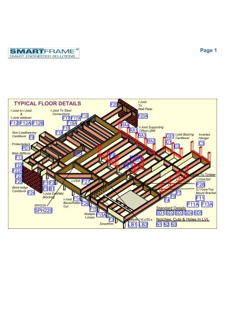
Page 1<br />
TYPICAL FLOOR DETAILS<br />
I-Joist to I-Joist<br />
&<br />
I-Joist setdown<br />
F12 F12A F12B<br />
Non-Loadbearing<br />
Cantilever<br />
Protectadeck<br />
F13<br />
F22<br />
F22A<br />
F23<br />
F25<br />
PD1<br />
Web-Stiffener<br />
Brick-ledge<br />
Cantilever<br />
F9<br />
F24<br />
SPH220<br />
F1 F2<br />
F5 B1<br />
SPH220<br />
I-Joist To Steel<br />
<strong>Connection</strong>s<br />
F17 F17A F19<br />
F18A<br />
F16<br />
F18<br />
I-Joist End/Mid<br />
Blocking<br />
I-Joist<br />
F10<br />
LVSIA<br />
Bevel/Rafter<br />
Cut<br />
F27<br />
F14<br />
F26<br />
F15<br />
F15A<br />
Multiple<br />
I-Joists<br />
F20<br />
F8<br />
F3<br />
SmartRim<br />
F20A<br />
RA4<br />
RA1<br />
RA3<br />
RA2<br />
F21<br />
F21A<br />
LB1<br />
I-Joist<br />
To<br />
Wall Plate<br />
I-Joist Supporting<br />
Offset LBW<br />
Multiple LVLs/GLs<br />
LB2<br />
CS1<br />
C1<br />
C2<br />
F7<br />
F4 F6<br />
Load Bearing<br />
Cantilever<br />
C3<br />
F28<br />
F11<br />
F11A F13A<br />
Standard <strong>Details</strong><br />
SD1 SD2 SD3 SD4 SD5<br />
Inverted<br />
Hanger<br />
I-Joist To <strong>Timber</strong><br />
LVSIA300<br />
SJ Face/Top<br />
Mount Bracket<br />
Notches, Cuts & Holes In LVL<br />
N1 N2 N3
FLOOR: SmartJOIST Supporting Offset Load Bearing Wall <strong>Details</strong><br />
RA1 Joist/Beam <strong>Connection</strong> details RA1<br />
Supporting offset load bearing walls<br />
RA1<br />
Brick<br />
or<br />
masonry<br />
wall<br />
UB, UC<br />
or Channel<br />
section<br />
Load bearing wall<br />
***Maximum roof area supported***<br />
As per table below<br />
Joist hanger to match joist size<br />
Joist span<br />
Maximum Roo f Area Supported (m2)<br />
Joist Spacing (mm) 300 400 450 600 300 400 450 600<br />
Joist Span (mm)<br />
Sheet Roof<br />
Tile Roo f<br />
6.7 5.7 3500 21.7 15.0 12.8 8.2 9.6 3.6<br />
4000 21.1 14.5 12.3 6.9 9.4 9.4 5.5 3.1<br />
4500 20.5 13.9 11.7 5.7 9.1 6.2 5.2 2.5<br />
5000 20.0 13.4 10.4 4.4 8.9 5.9 4.6 2.0<br />
5500 19.4 12.1 9.1 3.2 8.6 5.4 4.1 1.4<br />
**based upon worst case of 40mm flange width (conservative for wider flaged joists)<br />
RA1<br />
RA2 Joist/Beam <strong>Connection</strong> details RA2<br />
Supporting offset load bearing walls<br />
Load bearing wall<br />
***Maximum roof area supported***<br />
As per table below<br />
RA2<br />
UB, UC or<br />
Channel<br />
Section<br />
Rebate of<br />
12 mm Max<br />
Joist span<br />
Min bearing<br />
length of 35 mm<br />
Ma x im u m R o o f Ar ea Su p p o r ted ( m 2 )<br />
Jo is t Sp a cin g (m m ) 300 400 450 600 300 400 450 600<br />
Jo is t Sp a n (m m )<br />
Sh eet R o o f<br />
T ile o o f<br />
R 2.9 2.8 3500 6.9 6.4 6.2 5.3 3.1 2.4<br />
4000 6.7 6.2 6.0 4.6 3.0 2.8 2.7 2.0<br />
4500 6.6 6.0 5.7 3.9 2.9 2.7 2.5 1.7<br />
5000 6.4 5.8 5.1 3.1 2.9 2.6 2.3 1.4<br />
5500 6.3 5.3 4.6 2.4 2.8 2.4 2.0 1.1<br />
**based upon worst case of 40mm flange width (c onservative for wider flaged joists)<br />
Web-Stiffener<br />
as per detail F13<br />
50 mm ±<br />
50 mm ±<br />
F13<br />
Small Gap<br />
( 3mm ± )<br />
Nails, 4 of 3.15x65<br />
Clinched<br />
Tight Fit<br />
RA2<br />
RA3 Joist/Beam <strong>Connection</strong> details RA3<br />
Supporting offset load bearing walls<br />
***Concentrated Loads***<br />
Skew nail 2 of 3.15 x 75mm<br />
nails through to lower plate<br />
70 x 35 F5 nailed to underside<br />
of top flange of adjacent joists<br />
with 3.15 x 60 nails.<br />
90 x 45 F5 strut under<br />
concentrated load.<br />
Number of struts to match number<br />
of members in jamb stud or post<br />
RA3<br />
Stud or posts supporting<br />
truncated girder truss or<br />
other concentrated roof loads<br />
50 mm ±<br />
50 mm ±<br />
F13<br />
Small Gap<br />
( 3mm ± )<br />
Nails, 4 of 3.15x65<br />
Clinched<br />
Tight Fit<br />
Page 2<br />
RA3<br />
FLOOR: SmartJOIST Supporting Load Bearing Cantilever <strong>Details</strong><br />
C1<br />
SmartJoist<br />
blocking panel<br />
Refer to<br />
detail F15<br />
C1<br />
SmartJoist<br />
Load bearing cantilever details 1<br />
Web stiffeners required<br />
each side of ALL joists<br />
with reinforced cantilevers<br />
See detail F13<br />
Cantilever<br />
Span<br />
50 mm ±<br />
Equal to cantilever span<br />
but MINIMUM of 600mm<br />
NOTE:<br />
Block together full length with filler blocks as per<br />
detail F15 of the SmartJoist Design Guide<br />
***Tight Fit***<br />
50 mm ±<br />
F13<br />
C1<br />
Small Gap<br />
( 3mm ± )<br />
Nails, 4 of 3.15x65<br />
Clinched<br />
Tight Fit<br />
C1<br />
C2<br />
C2<br />
SmartJoist<br />
Load bearing cantilever details 2<br />
Web stiffeners required<br />
each side of ALL joists<br />
with reinforced cantilevers<br />
See detail F13<br />
50 mm ±<br />
50 mm ±<br />
F13<br />
Small Gap<br />
( 3mm ± )<br />
Nails, 4 of 3.15x65<br />
Clinched<br />
Tight Fit<br />
Face grain of ply<br />
reinforcement parallel<br />
to the span<br />
SmartJoist<br />
blocking<br />
panel<br />
Attach web-stiffeners<br />
to each side of joist<br />
over support<br />
Cantilever<br />
Span<br />
Equal to cantilever span<br />
but MINIMUM of 600mm<br />
NOTE:<br />
15mm F11 structural ply is required on one or both sides<br />
of the joist (See Tables). Depth shall match the full height<br />
of the Smartjoist. Nail with 3.15 x 65 nails at 100mm ctrs<br />
in a staggered pattern.<br />
C2<br />
17mm plywood<br />
or SmartRim closure<br />
C2<br />
C3<br />
50 mm ±<br />
50 mm ±<br />
C3<br />
SmartJoist<br />
blocking panel<br />
F13<br />
Small Gap<br />
( 3mm ± )<br />
Nails, 4 of 3.15x65<br />
Clinched<br />
Tight Fit<br />
SmartJoist<br />
Load Bearing Cantilever Detail<br />
(With INVERTED Face-Mount Hanger)<br />
INVERTED (Upside-down)<br />
Face-Mount<br />
Joist Hanger<br />
LVL Trimmer Beam<br />
25x10mm G.I. strap with<br />
7/35x3.15 dia. nails each end<br />
25x10mm G.I. strap with Inverted Face-Mount Hanger<br />
7/35x3.15 dia. nails each end<br />
Web-Stiffener to be installed<br />
See detail F13<br />
3 rows of 3.75 dia x 40 mm nails<br />
into the web-stiffener each side<br />
SmartJoist shall be designed<br />
to support load-bearing wall<br />
above when not stacked over<br />
wall below.<br />
Solid timber<br />
or LVL beam<br />
Cantilevered SmartJoist<br />
Web Stiffener<br />
Nail with 4 of 3.15dia x 65mm<br />
nails and clinched<br />
See detail F13<br />
C3<br />
25x10mm G.I. strap with<br />
7/35x3.15 dia. nails each end<br />
C3<br />
FLOOR: SmartJOIST Supporting Non-Load Bearing Cantilever <strong>Details</strong><br />
F9<br />
Protectadeck to be installed<br />
As per detail PD1<br />
Non Load bearing wall to a<br />
maximum height of 2400 mm<br />
SmartJoist<br />
Non load bearing cantilever details<br />
SmarJoist<br />
blocking<br />
200 x 50 mm Min.<br />
Nail to backer block & joist<br />
with 2 rows of 3.15 dia x 75 mm<br />
at 150 mm centres and clinch<br />
A<br />
70 mm<br />
MIN.<br />
Bearing.<br />
F9<br />
Min F8 - Durable or<br />
treated timber<br />
(UNIFORM LOADS ONLY).<br />
1200 mm MAX. 1200 mm MIN.<br />
L<br />
1.5 x L<br />
A<br />
Section A-A<br />
Backer block - Nail with 2 rows<br />
of 3.75 dia x 65 mm nails at<br />
150 centres and clinch<br />
Non Load bearing wall to a<br />
maximum height of 2400 mm<br />
NOTE: SmartJoists<br />
MUST BE PROTECTED<br />
FROM THE WEATHER<br />
UNIFORM LOADS ONLY.<br />
SmartJoist blocking<br />
SmartJoists may be cantilevered up to 1/3<br />
of their back span.<br />
L/3 MAX.<br />
Example 1200 mm<br />
L<br />
Example: 3600 mm<br />
F9<br />
FOR CANTILEVERS SUPPORTING LOAD BEARING WALLS<br />
SEE DETAILS C1 or C2.<br />
F9
Page 3<br />
FLOOR: SmartJOIST Brick Ledge Cantilever <strong>Details</strong><br />
F22<br />
SmartJoist<br />
F22<br />
Brick ledge cantilevers details<br />
SmartRim closure<br />
as per Detail C1 or C2.<br />
Between Joist blocking<br />
as per F1, alternative<br />
material, SmartRim<br />
F22A<br />
SmartJoist<br />
F22A<br />
Brick ledge cantilevers details<br />
3.7 x 75 mm nails,<br />
1 each side.<br />
Between Joist block I-Joist<br />
or SmartRim<br />
Load bearing<br />
stud wall.<br />
F23<br />
SmartJoist<br />
Brick ledge cantilevers details<br />
50mm min.<br />
from end joist<br />
300 mm<br />
Min<br />
F23<br />
Leave small<br />
gap approx 6 mm<br />
SmartRim or ply web<br />
fillers, both sides<br />
SmartRim or ply web<br />
fillers, both sides<br />
See detail F23<br />
SmartRim<br />
closure<br />
per detail<br />
C1 & C2<br />
Nail web filler with<br />
2 rows of 3.75 x 65<br />
nails , clinched.<br />
Refer to F22A<br />
for more details<br />
F22<br />
NOTE:<br />
THIS DETAIL NEEDS TO BE READ<br />
IN CONJUNCTION WITH DETAIL F23<br />
F22<br />
F22A<br />
SmartRim or ply web<br />
fillers, both sides<br />
See detail F23<br />
Brick veneer<br />
lower storey<br />
wall.<br />
Load Bearing<br />
Stud Wall.<br />
NOTE:<br />
THIS DETAIL NEEDS TO BE READ<br />
IN CONJUNCTION WITH DETAIL F23<br />
F22A<br />
F23<br />
160 mm Max<br />
NOTE: Refer to SmartJoist Design Guide<br />
For The Maximum Roof Area Supported<br />
For Different Joist Size/Type***<br />
F23<br />
FLOOR: SmartJOIST Brick Ledge Cantilever <strong>Details</strong> (Cont')<br />
F24<br />
SmartJoist<br />
Brick ledge cantilevers details<br />
300 mm<br />
Min<br />
F24<br />
SmartRim or Ply reinforcing.<br />
NOTE: For 360 and 400<br />
deep Joists, web fillers are<br />
required with reinforcement.<br />
F25<br />
SmartJoist<br />
F25<br />
Brick ledge cantilevers details<br />
Use SmartLVL15<br />
support joist to match<br />
<strong>SmartFrame</strong> I-Joist depths.<br />
Between Joist blocking -<br />
I-Joist, or SmartRim<br />
3.7 x 75 mm nails, 1 each side<br />
50 mm Min<br />
from end of joist<br />
Nail reinforcement<br />
with 2 rows of<br />
3.75 x 65 nails,<br />
clinched.<br />
SmartRim web fillers<br />
(WHERE REQUIRED)<br />
See detail F23 Loadbearing<br />
stud wall.<br />
F24<br />
160 mm Max<br />
NOTE: Refer to SmartJoist Design Guide<br />
For The Maximum Roof Area Supported<br />
For Different Joist Size/Type***<br />
F24<br />
F25<br />
Trimmer Joists to be MINIMUM of<br />
600 mm from inside of bearing<br />
plate to support LVL floor Joist.<br />
NOTE:<br />
THIS DETAIL NEEDS TO BE READ<br />
IN CONJUNCTION WITH DETAIL F23<br />
F25<br />
FLOOR: SmartJOIST to Solid <strong>Timber</strong> Fixing <strong>Details</strong><br />
F11 SmartJoist to LVL/Solid timber F11<br />
Face/Top mount connection details<br />
Solid timber<br />
or LVL beam<br />
F11A<br />
SmartJoist to LVL/GL Beams<br />
Face-mount connection detail<br />
Max. 3mm Gap<br />
F11A<br />
F13A SmartJoist to LVL/GL Beams F13A<br />
Face-mount connection detail<br />
Install web-stiffener & fix the face-mount hanger<br />
to the web-stiffener with 3 rows of 3.75dia x 40mm<br />
nails to acheive greater uplift capacity<br />
Resist Lateral Movement<br />
Resist Lateral Movement<br />
10mm Min.<br />
Face-Mount Hanger<br />
SmartLVL15<br />
SmartLam GL<br />
beams<br />
10mm Min.<br />
Top Flange<br />
of SmartJoist<br />
Restrained<br />
Top-mount<br />
hanger<br />
Face-mount<br />
hanger<br />
Top Flange<br />
of SmartJoist<br />
Restrained<br />
3 rows of 3.75 dia x 40 mm nails<br />
into the web-stiffener each side<br />
Web Stiffener<br />
Nail with 4 of 3.15dia x 65mm<br />
nails and clinched<br />
Refer to F13 detail below<br />
Small Gap<br />
( 3mm ± )<br />
30x6 gauge bugle-head<br />
or wafer-head wood screws<br />
50 mm ±<br />
F11<br />
If the sides of the hanger<br />
do not support the top flange.<br />
Web stiffeners as per<br />
Detail F13 are required.<br />
F11<br />
F11A<br />
30x6 gauge bugle-head<br />
or wafer-head wood screws<br />
F11A<br />
F13A<br />
F13<br />
50 mm ±<br />
Nails, 4 of 3.15x65<br />
Clinched<br />
Tight Fit<br />
F13A
Page 4<br />
FLOOR: SmartJOIST to Solid <strong>Timber</strong> Fixing <strong>Details</strong> (Cont')<br />
F27<br />
5.0 mm dia hole<br />
countersunk<br />
to underside<br />
Single SmartJoist to LVSIA<br />
<strong>Connection</strong> Detail<br />
6 of 7.0 mm<br />
dia holes<br />
SmartLVL Bearer/waling plate<br />
150mm<br />
20mm<br />
Skew nail top flange with<br />
3.15 x 65 mm nail to<br />
Bearer/Waling plate<br />
Min distance from both<br />
edges 10 mm<br />
75mm<br />
50mm<br />
minimum<br />
Fix angle plate to bearer<br />
or waling plate with<br />
6 No 12 x 35 mm long<br />
Type 17 Hexagonal<br />
head screws.<br />
F27<br />
F28<br />
3.75 x 75 nails at<br />
300mm spacing.<br />
As per detail F15/F15A<br />
3mm Gap<br />
As per F13 Detail<br />
Double/Triple SmartJoists to LVSIA<br />
<strong>Connection</strong> Detail<br />
5.0 mm dia hole<br />
countersunk<br />
to underside<br />
Fix top chord to support<br />
with 2/75x3.05mm nails<br />
per joist<br />
300mm<br />
12 of 7.0 mm<br />
dia holes<br />
20mm<br />
Min distance from both<br />
edges 10 mm<br />
75mm<br />
50mm<br />
minimum<br />
F28<br />
Notch bottom chord of SmartJoist<br />
55x5 mm for flush finish<br />
Min thickness of<br />
bearer/waling plate<br />
42 mm<br />
F27<br />
Notch bottom of<br />
joist for a flush<br />
finish, as per<br />
detail on page 11.<br />
Fix SmartJoist to angle<br />
plate with a 10 x 30 mm<br />
long type 17 counter - sunk screw.<br />
Min thickness of<br />
bearer/waling plate<br />
42 mm<br />
75 x 50 x 5 Unequal Angle<br />
150 mm long support, long<br />
Leg vertical - SEE ADJACENT F27<br />
DETAIL.<br />
Tight Fit<br />
Continuous Filler<br />
As per Detail F15/F15A<br />
F28<br />
****Tight Fit****<br />
Fix angle plate to bearer<br />
or waling plate with<br />
Fix SmartJoist to LVSIA Angle<br />
12 @ No. 12 x 35 mm long<br />
with 3 @ No. 10 x 30 mm<br />
Type 17 Hexagonal<br />
Type 17, Countersunk Screws<br />
head screws.<br />
75 x 50 x 5 Unequal Angle<br />
300 mm long support, long<br />
Leg vertical - SEE ADJACENT<br />
F28<br />
DETAIL.<br />
FLOOR: SmartJOIST to Brickwall Fixing <strong>Details</strong><br />
F20<br />
I-Joist to brick wall details<br />
With joist hanger & wall plate<br />
F20<br />
F20A<br />
I-Joist to Wall Plate details<br />
With Top-Mount Hanger<br />
F20A<br />
Brick or masonry wall<br />
Brick or masonry wall<br />
Masonry anchors to<br />
engineers design<br />
and installed to<br />
manufacturer's<br />
recommendations.<br />
3.15x50 FH NAILS<br />
@ 150CTS into wall plate<br />
Masonry anchors to<br />
engineers design<br />
and installed to<br />
manufacturer's<br />
recommendations.<br />
Joist hanger<br />
SmartLVL or similar<br />
plate, depth to approx<br />
match joist depth.<br />
Plywood Packer Plate<br />
Top-Mount<br />
Hanger<br />
SmartLVL or similar<br />
plate<br />
F20<br />
F20<br />
F20A<br />
F20A<br />
FLOOR: SmartJOIST to Steel Fixing <strong>Details</strong> (With Hanger)<br />
F17<br />
I-Joist to steel beam details<br />
With Top mount joist hanger<br />
F17<br />
F17A<br />
I-Joist to steel beam details<br />
With Top mount joist hanger<br />
F17A<br />
F19<br />
I-Joist to steel beam details<br />
With face mount hanger<br />
F19<br />
One bracket nail<br />
in every hole<br />
of the joist hanger.<br />
**Recommended***<br />
Fixing plate to be bolted to steel<br />
Bolt size as per eng. specification<br />
Bolts to be supplied by others<br />
Coach bolts<br />
Fixing plate<br />
bolted to steel<br />
(Bolts by other)<br />
Sheet flooring<br />
Filler block depth must<br />
fit all face mount nails<br />
***Minimum 35mm thick***<br />
70 mm vertical<br />
softwood packer<br />
at bolt location<br />
F17<br />
Top-Mount<br />
joist hanger<br />
to match joist size.<br />
UB, UC<br />
or Channel<br />
section<br />
Minimum 3mm, maximum 6mm<br />
space to eliminate contact between<br />
hanger and steel which may cause<br />
squeaks.<br />
NOTE:<br />
IT IS IMPORTANT TO USE THE CORRECT NAIL SIZE.<br />
WOOD MAY SPLIT IF THE NAILS ARE TOO LARGE.<br />
Nails should be 3.75 x 40 mm<br />
With a nail in EACH bracket hole.<br />
F17<br />
F17A<br />
SmartJoist<br />
SmartJoist<br />
UB, UC, PFC<br />
Top mount<br />
or Channel<br />
joist hanger<br />
section<br />
Minimum 3mm, maximum 6mm<br />
space to eliminate contact between<br />
hanger and steel which may cause<br />
squeaks.<br />
F17A<br />
Joist hanger as per<br />
this Design Guide<br />
F19<br />
Fixing plates: size dependent<br />
upon SmartJoist and steel<br />
beam sizes, but not less<br />
than 25 mm bearing<br />
onto steel beam<br />
Min of one M12 bolt every 1200 mm centres<br />
and not less than 3 bolts per filler block section,<br />
staggered where possible.<br />
Min edge and end distance of 60 mm.<br />
***All bolts to be supplied by others***<br />
F19
Page 5<br />
FLOOR: SmartJOIST to Steel Fixing <strong>Details</strong> (Without Hanger)<br />
F16<br />
F16<br />
I-Joist to steel beam details<br />
With Web Stiffener<br />
3-4 mm Gap<br />
12 mm Max<br />
Min Bearing length 45 mm<br />
DO NOT OVERCUT<br />
Web Stiffener installed<br />
in contact with bottom<br />
flange as per detail F13<br />
UB, UC or<br />
Channel<br />
Section<br />
1/No 10 x 30 mm Long<br />
Type 17 Screw.<br />
50 mm ±<br />
50 mm ±<br />
F13<br />
To maintain the End Reaction capacities above,<br />
End notching of flanges at supports is limited to:<br />
1. Notch depths no greater than 12 mm.<br />
2. Notches are not over cut.<br />
3. Notch does not exceed more than 5 mm past support.<br />
Small Gap<br />
( 3mm ± )<br />
F16<br />
Nails, 4 of 3.15x65<br />
Clinched<br />
Tight Fit<br />
F16<br />
F18<br />
D<br />
50 mm ±<br />
50 mm ±<br />
F18<br />
F13<br />
I-Joist to steel beam details<br />
With Web stiffener<br />
5 - 6 mm gap<br />
Small Gap<br />
( 3mm ± )<br />
Nails, 4 of 3.15x65<br />
Clinched<br />
Tight Fit<br />
20 mm (MAX)<br />
F18<br />
Web notch to be the min<br />
necessary for clearance.<br />
D/2 (Max)<br />
UB, UC<br />
or Channel Section<br />
Adequate lateral restraint<br />
Eg: blocking to lower flange<br />
or altenatively<br />
Min Bearing 1/No 10 x 30mm long<br />
length 35 mm type 17 screw as shown<br />
Web Stiffener installed<br />
in contact with bottom flange<br />
as per detail F13<br />
NOTE:<br />
Webs may be cut to accommodate the top flange<br />
of steel sections, provided that web stiffeners are installed<br />
both sides of the web as shown above and detail F13.<br />
F18<br />
F18A<br />
F18A<br />
<strong>SmartFrame</strong> I-Joist<br />
I-Joist to steel beam details<br />
With <strong>Timber</strong> packer<br />
2 of 3.15 x 65mm<br />
nails, one each side,<br />
a minimum of 30mm<br />
from the end<br />
<strong>Timber</strong> packer,<br />
minimum of 35mm<br />
bearing to steel<br />
and SmartJoist<br />
UB<br />
Steel Beam<br />
F18A<br />
22mm<br />
maximum<br />
rebate<br />
Packer to be securely<br />
fastened to steel beam<br />
F18A<br />
FLOOR: SJ Packer/Filler Block, SmartJOIST to SmartJOIST Fixing <strong>Details</strong><br />
F10<br />
SmartJoist<br />
Packer & Filler blocks details<br />
Packer block, nail<br />
with 10 of 3.75 dia<br />
x 75 nails.<br />
F10<br />
F11 SmartJoist to LVL/Solid timber F11<br />
Face/Top mount connection details<br />
Solid timber<br />
or LVL beam<br />
F12<br />
SmartJoist<br />
F12<br />
I-Joist to I-Joists connection details<br />
Filler blocking<br />
As per detail<br />
F15 or F15A<br />
Filler blocking<br />
nail with 10 of<br />
3.75 x 75 nails<br />
Top-mount<br />
hanger<br />
Top-mount<br />
hanger<br />
Filler block,<br />
nail with 10 of<br />
3.75 dia x 75 nails<br />
Face-mount<br />
hanger<br />
Nail backer blocking<br />
with 10 of 3.75 x 75 nails.<br />
F10<br />
F10<br />
F11<br />
If the sides of the hanger<br />
do not support the top flange.<br />
Web stiffeners as per<br />
Detail F13 are required.<br />
F11<br />
F12<br />
Backer block<br />
required<br />
F12<br />
FLOOR: SmartJOIST Set-Down Detail<br />
F12A<br />
REFER TO<br />
DETAIL F12B.2<br />
SmartJoist<br />
I-Joist to I-Joists<br />
Setdown details<br />
SETDOWN OR<br />
CHANGE IN LEVEL<br />
TOP-MOUNT HANGER<br />
FACE-MOUNT<br />
HANGER<br />
F12A<br />
BACKER BLOCK<br />
F12B<br />
50 mm ±<br />
50 mm ±<br />
F12B.1<br />
F12B.3<br />
Small Gap<br />
( 3mm ± )<br />
2 rows of<br />
3.75x75 nails<br />
at 150mm<br />
spacing<br />
Clinched<br />
Tight Fit<br />
For 2/40mm 2/44mm & 2/51mm<br />
with 1/setdown joist attached<br />
50 mm ±<br />
2 rows of<br />
3.75x75nails<br />
at 150mm<br />
spacing<br />
Clinched<br />
50 mm ±<br />
F12B.2<br />
F12B.4<br />
For 2/70mm 2/90mm & 3/SJs<br />
with 1/setdown joist attached<br />
Small Gap<br />
( 3mm ± )<br />
50 mm ±<br />
50 mm ±<br />
2 rows of<br />
3.15x65 nails<br />
at 150mm<br />
spacing<br />
Clinched<br />
F12B<br />
REFER TO<br />
DETAIL F12B.1<br />
F12A<br />
FILLER BLOCK<br />
REFER TO DETAIL<br />
F12B.3 OR FJ12B.4<br />
NOTE:<br />
THIS DETAIL NEEDS TO BE READ<br />
IN CONJUNCTION WITH DETAIL F12B<br />
TIGHT FIT<br />
NO GAPS<br />
F12A<br />
Small Gap<br />
( 3mm ± )<br />
50 mm ±<br />
2 rows of<br />
3.15x65nails<br />
at 150mm<br />
spacing<br />
Clinched<br />
50 mm ±<br />
F12B<br />
50 mm ±<br />
2 rows of<br />
3.75x75nails<br />
at 150mm<br />
spacing<br />
Clinched<br />
50 mm ±<br />
Small Gap<br />
( 3mm ± )<br />
50 mm ±<br />
2 rows of<br />
3.15x65nails<br />
at 150mm<br />
spacing<br />
Clinched<br />
50 mm ±<br />
50 mm ±<br />
2 rows of 3.75x75nails<br />
at 150mm spacing<br />
*each end*<br />
(Offset nails from<br />
opposite face by 75 mm)<br />
Clinched<br />
50 mm ±<br />
F12B
Page 6<br />
FLOOR: Web Stiffeners, Bevel Cut <strong>Details</strong><br />
F13<br />
50 mm ±<br />
50 mm ±<br />
3 mm min. gap<br />
F13<br />
SmartJoist<br />
Web Stiffener attachment details<br />
Tight Fit<br />
Concentrated Load<br />
3 mm min. gap<br />
Tight Fit<br />
F13<br />
NOTE:<br />
Small Gap<br />
( 3mm ± ) 1. Web stiffeners are NOT required at end<br />
bearing supports when span length are taken<br />
from the <strong>SmartFrame</strong> I-Joist Design Guide<br />
2. Web stiffeners may be required at inner<br />
Nails, 4 of 3.15x65 suuports. Consult the appropriate tables.<br />
Clinched<br />
3. Web stiffeners ARE required where the<br />
joist hanger does not support the top flange.<br />
WEB STIFFENERS:<br />
SJ20044: 15x60mm ply<br />
SJ24040: 15x60mm ply<br />
SJ24051: 19x60mm ply<br />
SJ24070: 2/15x60mm ply<br />
SJ24090: 2/19x60mm ply<br />
SJ30040: 15x60mm ply<br />
SJ30051: 19x60mm ply<br />
SJ30070: 2/15x60mm ply<br />
SJ30090: 2/19x60mm ply<br />
SJ36058: 2/12x60mm ply<br />
SJ36090: 2/19x60mm ply<br />
SJ40090: 2/19x60mm ply<br />
F13<br />
F14<br />
F14<br />
SmartJoist<br />
Bevel cut details<br />
DO NOT bevel cut<br />
joist beyond<br />
inside face of wall.<br />
NOTE:<br />
SmartJoist blocking or timber X - bracing<br />
required at bearing for lateral support.<br />
F14<br />
F14<br />
FLOOR: Multiple SmartJOIST <strong>Details</strong><br />
F15<br />
SmartJoist<br />
Multiple SmartJoist details 1<br />
F15<br />
F15A<br />
SmartJoist<br />
Multiple SmartJoist details 2<br />
F15A<br />
***Tight Fit***<br />
***Tight Fit***<br />
3mm Gap<br />
3mm Gap min.<br />
Tight Fit<br />
Continuous filler block<br />
3.75 x 75 nails at<br />
150 mm spacing.<br />
(Offset nails from<br />
opposite face by 75 mm)<br />
Tight Fit<br />
Continuous filler block<br />
3.75 x 75 nails at<br />
150 mm spacing.<br />
(Offset nails from<br />
opposite face by 75 mm)<br />
Small Gap<br />
( 3mm ± )<br />
Small Gap<br />
( 3mm ± )<br />
Min. 3mm Gap<br />
Min. 3mm Gap<br />
50 mm ±<br />
50 mm ±<br />
50 mm ±<br />
50 mm ±<br />
2 rows of<br />
3.75x75nails<br />
at 150mm<br />
spacing<br />
Clinched<br />
2 rows of 3.75x75nails<br />
at 150mm spacing<br />
****each end****<br />
(Offset nails from<br />
opposite face by 75 mm)<br />
Clinched<br />
2 rows of<br />
3.75x75nails<br />
at 150mm<br />
spacing<br />
Clinched<br />
2 rows of 3.75x75nails<br />
at 150mm spacing<br />
****each end****<br />
(Offset nails from<br />
opposite face by 75 mm)<br />
Clinched<br />
F15<br />
50 mm ±<br />
For 2/40mm 2/44mm & 2/51mm<br />
50 mm ±<br />
For 2/70mm 2/90mm & 3/SJs<br />
F15<br />
F15A<br />
50 mm ±<br />
For 2/40mm 2/44mm & 2/51mm<br />
50 mm ±<br />
For 2/70mm 2/90mm & 3/SJs<br />
F15A<br />
FLOOR: Multiple LVLs/GLs Laminating Detail & Protectadeck Detail<br />
LB1<br />
2 pieces of<br />
SmartLVL<br />
>= 58 mm<br />
LB1<br />
Bolting of SmartLVL/SmartLam<br />
2/58mm in width or greater<br />
Min. 50 mm<br />
Bolt top and bottom at ends<br />
300 mm<br />
600 mm<br />
12 mm MS Bolts<br />
LB1<br />
50 mm Min<br />
50 mm Min<br />
55 mm diameter<br />
washer as per<br />
AS1720.1 table 4.12<br />
Maximum Floor Load Width Supported By Either Outside Member (mm)<br />
12mm dia. Bolts<br />
2 rows at 600mm ctrs 2 rows at 300mm ctrs 3 rows at 600mm ctrs<br />
5600mm<br />
11000mm<br />
10200mm<br />
LB1<br />
LB2<br />
D<br />
LB2<br />
Multiple member of SmartLVL<br />
Laminating details<br />
(2/45mm in width or less)<br />
Multiple members laminating of TOP loaded beams<br />
Nails driven on alternate sides<br />
300 mm spacing<br />
Temporary<br />
waterproof<br />
membrane<br />
300 mm spacing<br />
Maximum Floor Load Width Supported By Either Ouside Member (mm)<br />
3.75 dia x 90mm nails<br />
2 rows at 300ctrs 3 rows at 300ctrs<br />
3400mm<br />
5100mm<br />
LB2<br />
Bead of<br />
elastometric<br />
adhesive<br />
LB2<br />
PD1<br />
PD1<br />
Protectadeck or<br />
similar impervious<br />
membrane to<br />
prevent water<br />
ponding on joist<br />
SmartLVL<br />
Protectadeck details<br />
H3 treated or Natural Durability<br />
class 1 or 2 (sapwood removed)<br />
decking<br />
PD1<br />
Skew deck<br />
nails slightly<br />
to cross<br />
multiple veneers<br />
(Galvanised helical<br />
threaded nails or<br />
screws)<br />
H3 treated SmartLVL joists<br />
NOTE:<br />
Deck/Balcony members to be sealed<br />
before & after installation.<br />
PD1
Page 7<br />
FLOOR: SJ Rafter Cut<br />
F26<br />
F26<br />
Rafter cuts of SmartJoist details<br />
FLOOR: SPH220 Split Hanger Fixing Detail<br />
SPH220<br />
SPH220<br />
Heavy Duty Beam Hanger<br />
Fixing detail<br />
SPH220<br />
1 MIN<br />
2<br />
Top flange must<br />
be braced either<br />
by sheeting or<br />
100 x 50 for<br />
lateral stability.<br />
32mm min.<br />
edge distance<br />
32mm min.<br />
edge distance<br />
115mm min.<br />
600mm<br />
Blocking<br />
90 mm<br />
Min bearing<br />
19 mm F11 Ply or SmartRim. Install<br />
reinforcement to both sides of joist using<br />
adhesive meeting AS/NZS 4364:1996<br />
and nail using 14/75 x 3.75mm evenly<br />
spaced as shown. Alternate nailing from<br />
each side and clinch.<br />
F26<br />
F26<br />
SPH220<br />
*******10 Screws to each face*******<br />
*****40 Screws required per pair*****<br />
(No.14 x 30mm min. length Type 17)<br />
SPH220<br />
FLOOR: SmartJOIST Supporting External/Internal LBW <strong>Details</strong><br />
F4<br />
SmartJoist<br />
Supporting external LBW details<br />
F4<br />
F6<br />
SmartJoist<br />
Supporting external LBW details<br />
F6<br />
F7<br />
SmartJoist details F7<br />
Interiror load bearing & bracing walls<br />
Load-bearing wall<br />
SmartJoist shall be designed<br />
to support load-bearing wall<br />
above when not stacked over<br />
wall below.<br />
Joist<br />
Bearer<br />
SmartJoist<br />
blocking panel<br />
Small section of bearer<br />
material placed on<br />
stumps/piers to<br />
support joists<br />
supporting parallel<br />
load-bearing walls<br />
F4<br />
F4<br />
F6<br />
Backer for siding<br />
attachment.<br />
Use double joists<br />
under wall where<br />
vertical load<br />
exceeds 29 kN/m<br />
F6<br />
F7<br />
NOTE:<br />
Detail F7 with blocking panel is<br />
required for bracing wall<br />
F7<br />
FLOOR: SmartJOIST Supporting External/Internal LBW <strong>Details</strong> (Cont')<br />
F8 SmartJoist details F8<br />
Interiror load bearing & bracing walls<br />
Load bearing wall<br />
above must stack<br />
over wall below<br />
2 mm<br />
90 X 45 F5 Cripple<br />
(compression block)<br />
skew nailed to both<br />
flanges with<br />
3.15 x 65 nails.<br />
F8<br />
F8
FLOOR: SmartJOIST Blocking & Rimboard Blcoking <strong>Details</strong><br />
F1<br />
SmartJoist<br />
Blocking details 1<br />
SmartJoist<br />
blocking panel<br />
F1<br />
F2<br />
SmartJoist<br />
Rim joist details<br />
SmartJoist<br />
rim joist<br />
F2<br />
F3<br />
SmartRim<br />
Rimboard details 1<br />
Page 8<br />
Butt sections together<br />
at centre of lower<br />
storey stud.<br />
SmartRim<br />
F3<br />
Single/Upper storey<br />
2 layers of<br />
SmartRim<br />
Rimboard<br />
F1<br />
F1<br />
F2<br />
F2<br />
F3<br />
Lower storey of two storey<br />
F3<br />
FLOOR: SmartJOIST Blocking & Rimboard Blcoking <strong>Details</strong> (Cont')<br />
F5<br />
SmartJoist<br />
Blocking detail 2<br />
F5<br />
B1<br />
SmartJoist<br />
Midspan blocking details<br />
B1<br />
Floor sheeting<br />
glued AND nailed<br />
to joists and blocking<br />
SmartJoist between<br />
joist blocking, skew nailed<br />
with 2.8 x 60mm nails.<br />
0.91 x 25mm galvanised<br />
mild steel strap fastened to<br />
joists, blocking panels and<br />
END WALLS with 40 x 2.5mm<br />
galvanised nails<br />
SmartJoist<br />
floor joist<br />
F5<br />
Solid block all posts<br />
from above to bearing below.<br />
F5<br />
B1<br />
B1<br />
FLOOR: SmartJOIST Tie-Down <strong>Details</strong><br />
F21<br />
F21<br />
SmartJoist<br />
F21<br />
Tie Down (Bracing Wall) <strong>Details</strong><br />
Seasoned timber<br />
blocking piece<br />
90 mm<br />
90 x 45 seasoned timber bridging cleat.<br />
Cleats to be placed no closer than 1500 mm.<br />
Bracing (Tie Down) wall<br />
M10 bolt<br />
Nails to locate bridging cleat<br />
against top flange as shown<br />
SmartJoist<br />
NOTE :<br />
1. ULTIMATE LIMIT STATE UPLIFT CAPACITY IS 6.5 KN<br />
2. DO NOT DRILL THROUGH EITHER FLANGE OF SmartJoist<br />
unless they are fully supported on wall plate or similar<br />
F21<br />
F21A<br />
Seasoned timber<br />
blocking piece<br />
F21A<br />
SmartJoist<br />
F21A<br />
Tie Down (Bracing Wall) <strong>Details</strong><br />
Bracing (Tie Down) wall<br />
M12 bolt<br />
It is IMPORTANT that this beam<br />
is nailed into joist hangers to<br />
prevent joists spreading under load<br />
Min 170x58mm SmartLVL15 bridging cleat.<br />
Cleat spacing to be governed by Joist<br />
strength calculations with applied uplift loads.<br />
NOTE :<br />
1. MAX force transfer of system 30.0 kN<br />
FB58170 Joist hangers<br />
(both up and down) with<br />
18 off 35 x 3.15mm<br />
Galvanised <strong>Timber</strong><br />
Connector Nails into web<br />
stiffeners/joist web<br />
17mm (minimum) F11 Ply<br />
Min of 170mm wide. Nail<br />
with 4 off 4.5 x 75 nails<br />
and clinch. Fit flush under<br />
top flange of SmartJoist<br />
2. DO NOT DRILL THROUGH EITHER FLANGE OF<br />
SmartJoist unless they are fully supported on wall plate<br />
or similar<br />
F21A<br />
CS1<br />
SmartJoist<br />
blocking<br />
panel<br />
CS1<br />
SmartJoist<br />
Cantilever cyclone strap tie-down<br />
<strong>Details</strong><br />
Pryda<br />
cyclone strap<br />
or equivalent<br />
Cyclone rod,<br />
nut and washer<br />
under plate<br />
CS1<br />
Web-stiffeners required<br />
each side of ALL joists<br />
with cyclone ties<br />
Cantilever<br />
Span<br />
Equal to cantilever span<br />
but MINIMUM of 600mm<br />
CS1
Page 9<br />
SmartFRAME "DO" / "DO NOT" details<br />
-DO NOT CUT OR NOTCH FLANGE<br />
-DO NOT OVER-CUT HOLES IN WEB<br />
-DON'T MAKE HOLES WITH HAMMER<br />
OTHER THAN PRE-PUNCHED KNOCKOUTS<br />
NOTCHES IN THE ENDS OF I-JOISTS<br />
-RAFTER CUTS ARE REQUIRED TO HAVE MIN. OF D/3<br />
REMAINING AT THE OUTER FACE & A MAX.<br />
SLOPE DISTANCE OF 3xD.<br />
-HOLES WITH SHARP CORNER NOT ALLOWED<br />
MAXIMUM NAIL DIAMETER 3.15mm<br />
DO NOT OVERCUT FLANGES.<br />
SUBSTANTIAL REDUCTIONS IN CAPACITY MAY OCCUR<br />
IF FLANGE ARE OVERCUT.<br />
FOR BEARERS & JOISTS ONLY:<br />
-MAX. HOLE DIMENSIONS & LOCATIONS WITHIN<br />
THE SPAN TO CONFORM TO Fig 4.1 OF AS1684.2<br />
-MAX. NOTCH (TENSION & COMPRESSION EDGE)<br />
DIMENSIONS & LOCATIONS WITHIN THE SPAN TO<br />
CONFORM TO Fig 4.1 OF AS1684.2<br />
DO NOT START TOE NAIL INTO<br />
THE CORNER OF THE FLANGE<br />
OR THE TOP OF THE FLANGE<br />
START TOE NAIL<br />
APPROXIMATELY 2/3<br />
UP THE SIDE OF THE<br />
FLANGE<br />
NAILS SHOULD BE AS FAR<br />
AS PRACTICAL FROM THE<br />
END OF THE JOIST<br />
To maintain the End Reaction capacities above,<br />
End notching of flanges at supports is limited to:<br />
notch depth<br />
12mm max<br />
1. Notch depths no greater than 12 mm.<br />
2. Notches are not over cut.<br />
3. Notch does not exceed more than 5 mm past support.<br />
SmartFRAME "DO" / "DO NOT" <strong>Details</strong> (Cont')<br />
I-JOIST TO I-JOIST CONNECTION<br />
WITH FACE-MOUNT HANGER<br />
CORRECT<br />
NAILING<br />
NAIL AT<br />
WRONG ANGLE<br />
NAIL TOO LONG<br />
BOTTOM FLANGE PULLING OFF WHEN<br />
BACKER BLOCK ON ONE SIDE ONLY<br />
BACKER BLOCKING EACH SIDE, HANGER NAILS<br />
MUST EXTEND PAST THE SUPPORTING JOISTS'S<br />
WEB MEMBER INTO THE BACKER BLOCKING.<br />
WITH TOP-MOUNT HANGER<br />
D<br />
60%<br />
of D<br />
Min.<br />
WEB-STIFFENER<br />
REQUIRED<br />
NO WEB RESISTANCE<br />
RESULTS IN ROTATION<br />
WEB-STIFFENER<br />
NOT REQUIRED<br />
HANGER SIDE FLANGE<br />
SUPPORTS JOIST<br />
TOP FLANGE<br />
WEB-STIFFENER<br />
REQUIRED<br />
HANGER SIDE FLANGE<br />
SHOULD BE AT LEAST 60%<br />
OF JOIST DEPTH.<br />
BACKER BLOCKS REQUIRED<br />
THE TOP FLANGE OF THE SUPPORTING JOIST<br />
MUST BE SUPPORTED BY BACKER BLOCKS TO<br />
PREVENT CROSS GRAIN BENDING AND ROTATION<br />
SmartFRAME Notches, Cuts & Holes In Beams, Bearer, Joists & Rafters<br />
NOTCHES, CUTS & HOLES<br />
IN BEAMS, BEARERS, JOISTS & RAFTERS<br />
For SmartLVL products ONLY<br />
NOTCHES, CUTS & HOLES<br />
IN BEAMS, BEARERS, JOISTS & RAFTERS<br />
For SmartLVL products ONLY<br />
NOTCHES, CUTS & HOLES<br />
IN BEAMS, BEARERS, JOISTS & RAFTERS<br />
For SmartLVL products ONLY<br />
D/2 max.<br />
D min.<br />
D, less<br />
than 200mm<br />
D<br />
100mm<br />
max.<br />
D/4 max.<br />
D<br />
D/4 max.<br />
D/4 max.<br />
D/8 or<br />
25mm<br />
max.<br />
NOTE: Not more than 3 holes<br />
per 1800 mm of span<br />
D/8 or 25mm max.<br />
D/3<br />
min.<br />
D/4 max.<br />
D, less than<br />
200mm<br />
D/3 min.<br />
Notch may<br />
be over<br />
support<br />
D<br />
Notch may<br />
be over<br />
support<br />
D/2 max.<br />
100mm<br />
max.<br />
D/3<br />
max.<br />
D/8 or<br />
25 mm max.<br />
D<br />
D/2 or<br />
100 mm max.<br />
6D<br />
min.<br />
D/8 or<br />
25mm<br />
max.<br />
D/2 or<br />
100mm max.<br />
D<br />
50mm<br />
min.<br />
NOTE: Not more than 3 holes<br />
per 1800 mm of span<br />
50 dia. max<br />
D, 200 mm<br />
or greater<br />
50mm min.<br />
D<br />
NOTE: Not more than 3 holes<br />
per 1800 mm of span<br />
B/4 max.<br />
6B min.<br />
B
Page 10<br />
TYPICAL ROOF DETAILS<br />
Birdsmouth Detail<br />
R1<br />
Bevel Cut Detail<br />
R2<br />
Rafter Fixed<br />
To Ridge Beam<br />
R7A<br />
R3A<br />
R7B<br />
R3B<br />
Rafter Supported<br />
On Beveled Plate<br />
R8 R10A<br />
R10B<br />
Roof Opening<br />
R11<br />
Lateral Restraint<br />
At Support<br />
R9A R9B R9C<br />
R4<br />
Outriggers<br />
to SJ rafter<br />
Rafter Cut Detail<br />
F26<br />
Box Gutter Detail<br />
BG1 BG2<br />
R5A R5B R5C<br />
Rafter Overhang<br />
With Beveled Plate<br />
R6A R6B<br />
Rafter Overhang<br />
With Birdsmouth Cut
Page 11<br />
ROOF: SmartJOIST Box-Gutter <strong>Details</strong><br />
BG1<br />
SmartJoist<br />
Box Gutter rebate details 1<br />
BG1<br />
BG2<br />
SmartJoist<br />
Box Gutter rebate details 2<br />
BG2<br />
300 mm<br />
90 x 45 F5 - 600 mm long<br />
both sides of the SmartJoist<br />
300 mm<br />
17 mm F14 ply - 600 mm long<br />
both sides of SmartJoist<br />
B max<br />
B max<br />
A<br />
A<br />
Fasten with 2 rows of 100 x 3.75mm nails<br />
at 150mm centres. (***Stagger rows***)<br />
Fasten with 3 rows<br />
of 100 x 3.75mm nails<br />
at 100mm centres.<br />
BG1<br />
A = 200*, 240 & 300 mm depth<br />
B = 50 mm when A = 240 mm<br />
B = 100 mm when A = 300 mm<br />
*200 mm - Requires ply infill, 90x45mm<br />
solid timber reinforecement is NOT suitable<br />
Refer to detail BG2<br />
BG1<br />
BG2<br />
A = 200*, 240 & 300 mm depth<br />
B = 50 mm when A = 240 mm<br />
B = 100 mm when A = 300 mm<br />
*200 mm - Requires ply infill, 90x45mm<br />
solid timber reinforecement is NOT suitable<br />
BG2<br />
ROOF: SmartJOIST Rafter Cut, Birdsmouth cut & Bevel Cut <strong>Details</strong><br />
F26<br />
Rafter cuts of SmartJoist details<br />
F26<br />
R1<br />
SmartJoist roof detail<br />
Birdsmouth cut<br />
(At low end of joist ONLY)<br />
(Limited to max. 600mm overhang)<br />
R1<br />
R2<br />
SmartJoist roof detail<br />
Bevel cut<br />
R2<br />
1 MIN<br />
2<br />
Top flange must<br />
be braced either<br />
by sheeting or<br />
100 x 50 for<br />
lateral stability.<br />
Web stiffeners required each<br />
side of SmartJoist.<br />
Bevel cut stiffeners to match<br />
roof slope. See Detail F13.<br />
Do not bevel cut<br />
joists beyond inside<br />
face of wall.<br />
115mm min.<br />
600mm<br />
Small Gap<br />
( 3mm ± )<br />
2/65 x 3.15mm nails<br />
(one each side)<br />
Exception : see rafter<br />
cut details<br />
F26<br />
Blocking<br />
90 mm<br />
Min bearing<br />
19 mm F11 Ply or SmartRim. Install<br />
reinforcement to both sides of joist using<br />
adhesive meeting AS/NZS 4364:1996<br />
and nail using 14/75 x 3.75mm evenly<br />
spaced as shown. Alternate nailing from<br />
each side and clinch.<br />
F26<br />
R1<br />
50 mm ±<br />
50 mm ±<br />
F13<br />
Nails,<br />
4/65 x 3.15mm<br />
Clinched<br />
Tight Fit<br />
Birdsmouth cut shall bear<br />
fully and not overhang the<br />
inside face of the plate.<br />
R1<br />
R2<br />
NOTE:<br />
SmartJoist blocking is required<br />
at bearing to provide lateral support.<br />
R2<br />
ROOF: SmartJOIST Rafter to Ridge Beam <strong>Details</strong><br />
R3A<br />
SmartJoist roof detail<br />
Rafter to ridge beam connection<br />
25x1.0mm G.I. strap<br />
with 7/35 x 3.15mm<br />
nails each end<br />
Bevelled web stiffener<br />
on both sides<br />
as per detail F13<br />
R3A<br />
R3B<br />
SmartJoist roof detail<br />
Rafter to ridge beam connection<br />
25x1.0mm G.I. strap<br />
with 7/35 x 3.15mm<br />
nails each end<br />
Bevelled web stiffener<br />
on both sides<br />
as per detail F13<br />
R3B<br />
Small Gap<br />
( 3mm ± )<br />
Small Gap<br />
( 3mm ± )<br />
50 mm ±<br />
50 mm ±<br />
Nails,<br />
4/65 x 3.15mm<br />
Clinched<br />
Nails,<br />
4/65 x 3.15mm<br />
Clinched<br />
50 mm ±<br />
Tight Fit<br />
F13<br />
Variable Slope & Skew<br />
Joist Hanger<br />
50 mm ±<br />
Tight Fit<br />
F13<br />
Face-Mount Hanger<br />
(For roof pitch equal/less<br />
than 3 deg ONLY)<br />
R3A<br />
Note:<br />
Additional connection may required for wind uplift.<br />
R3A<br />
R3B<br />
Note:<br />
Additional connection may required for wind uplift.<br />
R3B
Page 12<br />
ROOF: Pine Outriggers to SmartJOIST Rafter Detail<br />
R4<br />
SmartJoist roof detail<br />
Outriggers to rafter connection<br />
R4<br />
Joist shall be designed using design<br />
properties when "L" exceeds joist spacing.<br />
600 mm<br />
MAX.<br />
L L<br />
50mm width overhang rafters.<br />
Notch around SmartJoist<br />
top flange.<br />
Blocking<br />
between outriggers<br />
R4<br />
Note:<br />
Additional connection may required for wind uplift.<br />
R4<br />
ROOF: SmartJOIST Rafter Overhang With Beveled Plate <strong>Details</strong><br />
R5A<br />
SmartJoist roof detail<br />
Lumber overhang with beveled plate<br />
R5A<br />
R5B<br />
SmartJoist roof detail<br />
Rafter overhang with beveled plate<br />
R5B<br />
R5C<br />
SmartJoist roof detail<br />
Rafter overhang with beveled plate<br />
R5C<br />
R5A<br />
50mm width cripple, cut under 90 x 45<br />
rafter extension (Web stiffener other side)<br />
1200 mm<br />
Beveled plate<br />
at bearing<br />
Use 2 rows of 65 x 3.15mm<br />
nails at 200 mm centres<br />
600mm max. overhang<br />
1200mm min. backspan<br />
600mm max. rafter spacing<br />
600 mm<br />
MAX<br />
Note:<br />
Additional connection may required for wind uplift.<br />
R5A<br />
minigrips as per<br />
manufacturer<br />
specification<br />
Web-stiffener<br />
as per detail F13<br />
R5B<br />
600 mm.<br />
max.<br />
Fix rafters to beveled plate<br />
with 1/75 x 3.15mm nail<br />
(one on each side)<br />
50 mm beveled plate for slopes<br />
greater than 1 degree.<br />
Note:<br />
Additional connection may required for wind uplift.<br />
tie-down as per<br />
manufacturer<br />
specification<br />
Fascia fixed to end of rafters<br />
with nail into web-stiffener,<br />
top flange & bottom flange<br />
R5B<br />
R5C<br />
50 mm beveled plate for slopes<br />
greater than 1 degree.<br />
Trim & add blocking<br />
(one each side)<br />
as desired for fascia support<br />
(cut to fit)<br />
Use 2 rows of 75 x 3.15mm<br />
nails at 100 mm centres<br />
Note:<br />
Additional connection may required for wind uplift.<br />
R5C<br />
ROOF: SJ Rafter Overhang With Birdsmouth Cut<br />
R6A<br />
SmartJoist roof detail<br />
Rafter overhang with birdsmouth cut<br />
R6A<br />
R6B<br />
SmartJoist roof detail<br />
Rafter overhang with birdsmouth cut<br />
R6B<br />
Web stiffeners required<br />
each side<br />
tie-down as per<br />
manufacturer<br />
specification<br />
tie-down as per<br />
manufacturer<br />
specification<br />
Birdsmouth cut<br />
at bearing<br />
Small Gap<br />
( 3mm ± )<br />
Birdsmouth cut<br />
at bearing<br />
R6A<br />
.<br />
600 mm<br />
MAX<br />
Use 2 rows of 75 x 3.15mm<br />
nails at 100 mm centres<br />
Extension rafter on both sides<br />
for facia support (cut to fit)<br />
Note:<br />
Additional connection may required for wind uplift.<br />
R6A<br />
50 mm ±<br />
50 mm ±<br />
R6B<br />
F13<br />
Nails,<br />
4/65 x 3.15mm<br />
Clinched<br />
Tight Fit<br />
.<br />
600 mm<br />
MAX<br />
Web stiffener required<br />
both sides<br />
See detail F13<br />
Note:<br />
Additional connection may required for wind uplift.<br />
R6B
Page 13<br />
ROOF: SmartJOIST Rafters - Peak <strong>Connection</strong> <strong>Details</strong><br />
SmartJoist roof detail<br />
SmartJoist roof detail<br />
R7A Peak connection R7A R7B<br />
R7B<br />
Peak connection<br />
R8<br />
SmartJoist roof detail<br />
Peak connection<br />
R8<br />
Bevelled web stiffener<br />
on both sides<br />
as per detail F13<br />
25x1.0mm G.I. strap<br />
with 7/35 x 3.15mm<br />
nails each end<br />
Bevelled web stiffener<br />
on both sides<br />
as per detail F13<br />
25x1.0mm G.I. strap<br />
with 7/35 x 3.15mm<br />
nails each end<br />
Panel backer block<br />
on both sides<br />
(With 18 nails)<br />
Beveled plate<br />
***Birdsmouth cut not permitted***<br />
Small Gap<br />
( 3mm ± )<br />
Small Gap<br />
( 3mm ± )<br />
50 mm ±<br />
50 mm ±<br />
50 mm ±<br />
F13<br />
Nails,<br />
4/65 x 3.15mm<br />
Clinched<br />
Tight Fit<br />
Variable Slope & Skew<br />
Joist Hanger<br />
50 mm ±<br />
F13<br />
Nails,<br />
4/65 x 3.15mm<br />
Clinched<br />
Tight Fit<br />
Face-Mount Hanger<br />
(For roof pitch equal/less<br />
than 3 deg ONLY)<br />
Twist Strap on both sides<br />
No. of nails & nail size as per<br />
manufacturer specification<br />
30 degrees max. angle<br />
R7A<br />
Note:<br />
Additional connection may required for wind uplift.<br />
R7A<br />
R7B<br />
Note:<br />
Additional connection may required for wind uplift.<br />
R7B<br />
R8<br />
Note:<br />
Additional connection may required for wind uplift.<br />
R8<br />
ROOF: SmartJOIST Rafter - Lateral Restraint At Support<br />
R9A<br />
Rim Board Blocking.<br />
(Toe nail to top plate at<br />
150mm on center.)<br />
Install as joists are set.<br />
SmartJoist roof detail<br />
Lateral support<br />
(rimboard blocking panel)<br />
R9A<br />
Bevelled web stiffener<br />
on both sides<br />
as per detail F13<br />
R9B<br />
SmartJoist roof detail<br />
Lateral support<br />
(I-Joist blocking panel)<br />
Fix roof batten to rafter<br />
with 2/35 x 3.15mm nails<br />
R9B<br />
Fix roof batten to blocking<br />
with 2/35 x 3.15mm nails<br />
R9C<br />
Metal strap over rafter<br />
SmartJoist roof detail<br />
Lateral support<br />
(Metal straps)<br />
Roof batten<br />
Nail metal strap to rafters<br />
and supports with<br />
3/35 x 3.15mm nails<br />
R9C<br />
Small Gap<br />
( 3mm ± )<br />
50 mm ±<br />
50 mm ±<br />
R9A<br />
F13<br />
Nails,<br />
4/65 x 3.15mm<br />
Clinched<br />
Tight Fit<br />
Beveled plate or<br />
Birdsmouth cut<br />
at bearing<br />
Note:<br />
Additional connection may required for wind uplift.<br />
R9A<br />
R9B<br />
Fix cut-to-length<br />
blocking to support<br />
with 4/65 x 3.15mm nail<br />
per each blocking<br />
Beveled plate or<br />
Birdsmouth cut at bearing<br />
Note:<br />
Additional connection may required for wind uplift.<br />
R9B<br />
R9C<br />
Beveled plate or<br />
Birdsmouth cut at bearing<br />
Note:<br />
Additional connection may required for wind uplift.<br />
R9C<br />
ROOF: SJ Rafters On Beveled Plate <strong>Details</strong><br />
SmartJoist roof detail<br />
R10A<br />
Rafter supported on beveled plate<br />
R10A<br />
Fix rafters to support<br />
with 1/75 x 3.15mm nail<br />
(one on each side)<br />
25x1.0mm G.I. strap<br />
with 7/35 x 3.15mm<br />
nails each end<br />
Blocking panel<br />
SmartJoist roof detail<br />
R10B<br />
R10B<br />
Rafter supported on beveled plate<br />
Fix rafters to support<br />
with 1/75 x 3.15mm nail<br />
(one on each side)<br />
600mm<br />
Blocking panel<br />
ROOF: Roof Opening<br />
R11<br />
Filler blocking<br />
As per detail<br />
F15 or F15A<br />
SmartJoist roof detail<br />
Roof Opening<br />
Nail backer blocking<br />
with 75 x 3.15mm nails.<br />
Refer to table below<br />
for no. of nails required<br />
Strap<br />
R11<br />
Double-beveled<br />
plate on beam or wall<br />
R10A<br />
Tie-down as per<br />
manufacturer specification<br />
Note:<br />
Additional blocking may be required for shear transfer<br />
R10A<br />
R10B<br />
RimBoard or filler block on both sides.<br />
(With 12 nails on each side of ridge)<br />
Double-beveled<br />
plate on beam or wall<br />
Note:<br />
Additional connection may required for wind uplift.<br />
R10B<br />
R11<br />
Face-Mount<br />
Hanger<br />
Side Load (kg) No. of backer nails Required<br />
227 8<br />
340 12<br />
454 16<br />
567 20<br />
680 24<br />
794 28<br />
907 32<br />
Backer block<br />
on both sides<br />
R11