View TurboGen⢠Procedure - Turbine Technologies
View TurboGen⢠Procedure - Turbine Technologies
View TurboGen⢠Procedure - Turbine Technologies

Create successful ePaper yourself
Turn your PDF publications into a flip-book with our unique Google optimized e-Paper software.
TurboGen TM Gas <strong>Turbine</strong> Power System Lab Experiment Manual<br />
Lab Session #5: Electrical Generation Performance Analysis<br />
Purpose: To determine optimal operational settings for the SR-30 Gas <strong>Turbine</strong><br />
Engine to calculate Power Specific Fuel Consumption in the process of<br />
generating Electricity.<br />
<strong>Procedure</strong>: Perform requested analysis and calculations that follow.<br />
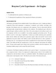
TurboGen generates electricity by thermodynamically spinning a turbine wheel, which<br />
drives an electric alternator. A basic electric schematic of the electric alternator system<br />
is shown in Figure 1.<br />
The alternator consists<br />
of two basic<br />
components; a rotor and<br />
a stator. The rotor is an<br />
electromagnet (not<br />
permanent), so it needs<br />
Excitation Current for it<br />
to generate electricity.<br />
The rotor spins, creating<br />
a voltage<br />
The rotor consists of a<br />
coil of wire wrapped<br />
around an iron core.<br />
Current through the wire<br />
coil - called "field"<br />
current - produces a<br />
magnetic field around<br />
the core. The strength of<br />
the field current<br />
determines the strength<br />
of the magnetic field. The<br />
Excitation<br />
Current<br />
Stator<br />
Rotor<br />
Stator<br />
Figure 1: Electric Alternator<br />
field current is D/C, or direct current. In other words, the current flows in one direction<br />
only, and is supplied to the wire coil by a set of brushes and slip rings. The magnetic<br />
field produced has, as any magnet, a north and a south pole. The rotor is driven by the<br />
alternator pulley, rotating as the engine runs, hence the name "rotor."<br />
Surrounding the rotor is another set of coils, three in number, called the stator. The<br />
stator is fixed to the shell of the alternator, and does not turn. As the rotor turns within<br />
the stator windings, the magnetic field of the rotor sweeps through the stator windings,<br />
producing an electrical current in the windings. Because of the rotation of the rotor, an<br />
alternating current is produced. As, for example, the north pole of the magnetic field<br />
approaches one of the stator windings, there is little coupling taking place, and a weak<br />
current is produced, As the rotation continues, the magnetic field moves to the center of<br />
N<br />
S<br />
R<br />
Copyright April, 2010<br />
20<br />
<strong>Turbine</strong> <strong>Technologies</strong>, Ltd.