S3® Proximal Humerus Plating System Surgical Technique - Biomet
S3® Proximal Humerus Plating System Surgical Technique - Biomet
S3® Proximal Humerus Plating System Surgical Technique - Biomet

Create successful ePaper yourself
Turn your PDF publications into a flip-book with our unique Google optimized e-Paper software.
®<br />
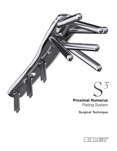
<strong>Proximal</strong> <strong>Humerus</strong><br />
<strong>Plating</strong> <strong>System</strong><br />
<strong>Surgical</strong> <strong>Technique</strong>
S3 ® <strong>Proximal</strong> <strong>Humerus</strong> <strong>Plating</strong> <strong>System</strong><br />
Contents<br />
Introduction................................................................................................................................................................... 3<br />
S3 ® <strong>Proximal</strong> <strong>Humerus</strong> <strong>Plating</strong> <strong>System</strong>........................................................................................................................ 4<br />
Deltopectoral Approach................................................................................................................................................ 6<br />
<strong>Surgical</strong> <strong>Technique</strong>........................................................................................................................................................ 8<br />
Ordering Information................................................................................................................................................... 14<br />
1
S3 ® <strong>Proximal</strong> <strong>Humerus</strong> <strong>Plating</strong> <strong>System</strong><br />
Introduction<br />
<strong>Biomet</strong>’s experience in developing implants for fracture<br />
fixation through locked plating technology has been used<br />
to design the S 3® plate for the management of proximal<br />
humerus fractures. The S 3® <strong>Proximal</strong> <strong>Humerus</strong> Plate takes<br />
full advantage of the principle of spatial subchondral support<br />
successfully applied in the design of its sister product,<br />
the DVR® Anatomic distal volar radius plate.<br />
The S 3® system is designed around the natural anatomy<br />
of the proximal humerus to address varus collapse.<br />
Convergent and divergent fixed angle pegs are centered<br />
around the natural 135° neck-shaft angle of the proximal<br />
humerus. The central guiding k-wire provides visual<br />
confirmation for plate positioning, ensuring that the predetermined<br />
peg trajectories will provide consistent spatial<br />
distribution within the humeral dome. This unique concept<br />
of humeral fixation helps resist varus forces throughout the<br />
full range of motion.<br />
The S 3® pegs and screws utilize blunt smooth ends so that<br />
fixation can be provided directly below the hard articular<br />
shell. Engaging the subchondral bone with blunt fixation<br />
and the use of a manually inserted blunt-tipped drill bit,<br />
reduces the risk for articular surface penetration.<br />
Intended Use<br />
The S 3® <strong>Proximal</strong> <strong>Humerus</strong> Plate is indicated for fractures<br />
and fracture dislocations, osteotomies, and non-unions of<br />
the proximal humerus.<br />
<strong>Surgical</strong> Approach<br />
<strong>Proximal</strong> Humeral fractures are treated with the S 3® through<br />
the deltopectoral approach. S 3® <strong>Proximal</strong> <strong>Humerus</strong> <strong>Plating</strong><br />
<strong>System</strong>.<br />
The S 3® plate has been designed to help prevent subacromial<br />
impingement. The unique design of the S 3® allows the<br />
plate to be positioned more distally, minimizing the risk of<br />
impingement.<br />
3
S 3®<br />
<strong>Proximal</strong> <strong>Humerus</strong> <strong>Plating</strong> <strong>System</strong><br />
Minimizes Subacromial Impingement<br />
• The S 3® plate is designed to be positioned approximately<br />
3.0 cm distal to the greater tuberosity helping<br />
to prevent subacromial impingement<br />
3.0 cm<br />
Minimizes Varus Collapse<br />
• The parametric design of the pegs distribute the loads<br />
more anatomically through the full range of motion by<br />
maintaining the neck shaft angle of 135º minimizing<br />
the risk of varus collapse<br />
Provides Strong and Secure Fixation<br />
• The proximal end of the S 3® plate has fixed angle<br />
locking pegs/screw holes. Its parametric design of<br />
convergent and divergent screw trajectories ensures<br />
a consistent spatial distribution of the pegs within<br />
the entire humeral head. This particular distribution<br />
provides spatial subchondral support to resist varus<br />
forces throughout the full range of motion.<br />
• 4.0 mm blunt tipped subchondral support smooth or<br />
threaded pegs, provide stability while preventing protrusion<br />
through the articular surface<br />
135˚<br />
• <strong>Proximal</strong> and distal locking pegs and screws provide a<br />
strong interface for a stable fixation.<br />
4
Ease of Use<br />
F.A.S.T. Guide ® Technology<br />
The S 3® plate comes preloaded with Fixed<br />
Angle Screw Targeting Guides – F.A.S.T. Guide<br />
Technology – facilitating accurate drilling and easy<br />
plate identification (left vs right).<br />
Central K-wire<br />
Central K-wire hole provides a guide for initial plate<br />
positioning through the use of fluoroscopy and<br />
temporary fixation.<br />
Suture Holes<br />
Suture holes allow for simplified tuberosity repairs<br />
after humeral head fixation through frontal and<br />
lateral access.<br />
User Friendly <strong>System</strong> Design<br />
Intuitive set layout and simple instrumentation allow<br />
for convenience in surgery.<br />
5
S 3®<br />
<strong>Proximal</strong> <strong>Humerus</strong> <strong>Plating</strong> <strong>System</strong><br />
Figure 1. Figure 2.<br />
Cephalic vein<br />
Figure 3.<br />
Deltopectoral Approach<br />
Patient positioning and approach<br />
The procedure can be performed in the beach-chair position<br />
or supine position (Figure 1) as per the surgeon’s<br />
discretion. If necessary, a sterile mayo stand can be used<br />
to assist during dissection.<br />
Assess the fracture fluoroscopically.<br />
Examine the fracture based on intraoperative fluoroscopy.<br />
Internal rotation, external rotation and sometimes axillary<br />
views are necessary (Figure 2).<br />
Exposure<br />
Make an incision approximately 12–14 cm over the coracoid<br />
process, extending down to the deltoid insertion in<br />
an oblique fashion. Identify and retract the cephalic vein<br />
(Figure 3).<br />
Note: Taking the cephalic vein medially provides additional<br />
protection against perforation during drilling.<br />
6
Figure 4.<br />
Figure 6.<br />
Figure 5.<br />
Identify the Biceps Tendon<br />
Gently retract the coracobrachialis medially. Find the pectoralis<br />
insertion at the floor of the deltoid pectoralis interval<br />
(Figure 4). If necessary, release the proximal third of the<br />
pectoralis tendon to expose the biceps.<br />
Complete Exposure<br />
Develop the subacromial space and mobilize the proximal<br />
deltoid (Figure 5).<br />
Fracture Debridement and Reduction<br />
Reduce the humeral head fragments using traction and<br />
manipulation and check the reduction under fluoroscopy<br />
(Figure 6).<br />
Note: In the case of severe comminution, suturing the<br />
rotator cuff together will help reduce the tuberosities. To<br />
facilitate healing, bone graft should be considered.<br />
Note: Use of a large, blunt humeral head depressor can<br />
facilitate exposure.<br />
7
S 3®<br />
<strong>Proximal</strong> <strong>Humerus</strong> <strong>Plating</strong> <strong>System</strong><br />
Figure 9.<br />
Figure 7. Figure 8.<br />
<strong>Surgical</strong> <strong>Technique</strong><br />
Plate Positioning<br />
Select the appropriate side plate (lime=left; rose=right) and<br />
length (3,4,6,8,11 or 14 hole) (Figure 7).<br />
Position the plate 2.5–3.0 cm distal to the greater tuberosity.<br />
The anterior border of the plate (straight border) should<br />
be immediately lateral to the bicepital groove (Figure 8).<br />
Drill Central K-Wire<br />
Drill the 2.0 mm K-wire (KW20SS) through the central<br />
K-wire hole on the proximal portion of the plate aiming the<br />
center of the humeral head (Figure 9).<br />
8
135˚<br />
Figure 10.<br />
Figure 12.<br />
Figure 11.<br />
Verify Central K-Wire<br />
Check the trajectory of the central K-wire under fluoroscopy.<br />
If there’s a deviation from the center of the humeral<br />
head remove the K-wire and redrill until the center is<br />
reached (Figure 10).<br />
Note: Other distal K-wire hole can be used to aid in fracture<br />
reduction and provisionally fix the plate to the bone.<br />
Distal Plate Provisional Fixation<br />
Drill through the oblong hole of the plate shaft with the<br />
2.8 mm Drill Bit (DB28), using the Soft Tissue Protector<br />
(SSTG) (Figure 11).<br />
Determine the required screw depth using the Depth<br />
Gauge (SBDG) (Figure 12).<br />
9
S 3®<br />
<strong>Proximal</strong> <strong>Humerus</strong> <strong>Plating</strong> <strong>System</strong><br />
Figure 13.<br />
5<br />
1<br />
3<br />
6<br />
2<br />
Figure 15.<br />
4<br />
Figure 14.<br />
Fix the plate into place with a 3.8 mm Multidirectional<br />
Cortical Screw (MDXX) using the Hex Driver (FHDS)<br />
(Figure 13).<br />
Note: Do not fully tighten the screw to allow for later<br />
plate adjustments.<br />
<strong>Proximal</strong> Plate Fixation<br />
Drill through the inferior anterior F.A.S.T. Guide with the<br />
4.0 mm Short Drill Bit (FDB40S), and perforate the cortex<br />
(Figure 14). The drill bit has a stop that will only allow it to<br />
penetrate the near cortex.<br />
Note: The K-wire can be bent to avoid drill bit obstruction.<br />
Manual Drill for Subchondral Support Pegs<br />
To prevent the drill from protruding through the rear cortex<br />
the following step should be made by manual drilling<br />
(Figure 15).<br />
With the 4.0 mm Long Drill Bit (FDB40L or FDS40) attached<br />
to the Driver Handle (QCH), advance through the<br />
proximal plate hole F.A.S.T. Guide until resistance from<br />
subchondral bone is felt. This will ensure the peg engages<br />
subchondral bone for optimal fixation.<br />
Note: Do not use powered drilling for inserting the subchondral<br />
pegs. When manual drilling for smooth pegs<br />
use FDB40L. When manual drilling for partially threaded<br />
pegs use FDS40.<br />
Note: To aid with peg engagement, start with the anterior<br />
and posterior inferior peg holes first, and then finish<br />
by drilling the remaining proximal holes in a crisscross,<br />
opposing fashion.<br />
10
Figure 16.<br />
Figure 18.<br />
Figure 17.<br />
Determine Peg Length<br />
Once resistance is felt, fluoroscopy imaging should verify<br />
that the tip of the manual drill is close to the subchondral<br />
bone (Figure 16 & 17). Care should be taken not to penetrate<br />
the subchondral bone. Use the appropriate side of<br />
the dual scale drill bit to determine the correct peg size.<br />
Peg Insertion<br />
Remove and discard the respective F.A.S.T. Guide and insert<br />
the appropriate size peg using the Hex Driver (FHDS)<br />
(Figure 18).<br />
Note: If the pegs do not engage initially, re-insert the<br />
F.A.S.T. Guide or drill guide (DRGSH) and drill again<br />
using the hand drill (FDB40L)<br />
Note: If a F.A.S.T. Guide was removed before the screw<br />
length was recorded, insert the 4.0 mm Drill Guide<br />
(DRGSH) and measure using the appropriate side of the<br />
dual scale stepped Depth Gauge (FSDGS).<br />
11
S 3®<br />
<strong>Proximal</strong> <strong>Humerus</strong> <strong>Plating</strong> <strong>System</strong><br />
Figure 20.<br />
Figure 22.<br />
Figure 21.<br />
Attach Tuberosities to Plate<br />
Secure the tuberosities to the plate by passing the needles<br />
close to the insertion of the tendon and then through to<br />
side, front or top loading wire attachment points found on<br />
the proximal end of the plate (Figure 20).<br />
Note: An alternate approach is to apply the sutures to<br />
the plate prior to placing the subchondral support pegs.<br />
This may aid in reduction.<br />
Insert Distal Screws<br />
Use the appropriate end of the Soft Tissue Protector<br />
(SSTG) and drill to the far cortex with the 2.8 mm Drill Bit<br />
(DB28) (Figure 21). Measure with the Barrel Depth Gauge<br />
(SBDG)<br />
Fix the remaining Shaft Cortical Screws with either 90º<br />
Locking Screws (NLXX) or Multidirectional Screws (MDXX)<br />
(Figure 22).<br />
Use a Set Screw (NLSS) to lock each 90º Screw to the<br />
plate. Do not use a set screw when using Multidirectional<br />
Screws.<br />
12
Figure 23. Figure 24.<br />
Final Verification<br />
Evaluate the humerus under fluoroscopy to assess<br />
the reduction and to confirm proper plate positioning<br />
(Figure 23 & 24).<br />
13
S 3®<br />
<strong>Proximal</strong> <strong>Humerus</strong> <strong>Plating</strong> <strong>System</strong><br />
Ordering Information<br />
Pegs and Screws<br />
Smooth Peg, Locking<br />
Provide spatial subchondral support.<br />
Cat No STPXX<br />
20, 25 and 30–65 mm lengths (2.5 mm steps)<br />
Threaded Pegs, Locking<br />
Help to capture and lag the humeral head.<br />
Cat No STPTXX<br />
20, 25 and 30–65 mm lengths (2.5 mm steps)<br />
90˚ Cortical Screws, Non-locking<br />
Provide bi-cortical fixation while locking to the<br />
plate using the NLSS set screws.<br />
Cat No NLXX<br />
20 mm – 38 mm lengths (2.0 mm steps)<br />
Multi-directional Cortical Screws,<br />
Non-Locking<br />
Provide multi-directional fixation when used<br />
through the oblong hole.<br />
Cat No MDXX<br />
20 mm – 38 mm lengths (2.0 mm steps)<br />
90˚ Locking Set Screw<br />
Secures the 90˚ lock distal screws to the plate.<br />
Cat No NLSS<br />
S 3® <strong>Proximal</strong> <strong>Humerus</strong> <strong>Plating</strong> <strong>System</strong> Options<br />
Lime=Left; Rose=Right<br />
S 3® Plate, 3 Holes:<br />
16 mm x 71 mm<br />
SSPL3 / SSPR3<br />
S 3® Plate, 4 Holes:<br />
16 mm x 84 mm<br />
SSPL4 / SSPR4<br />
S 3® Plate, 6 Holes:<br />
16 mm x 108 mm<br />
SSPL6 / SSPR6<br />
S 3® Plate, 8 Holes:<br />
16 mm x 150 mm<br />
SSPL8 / SSPR8<br />
S 3® Plate, 11 Holes:<br />
16 mm x 190 mm<br />
SSPL11 / SSPR11<br />
S 3® Plate, 14 Holes:<br />
16 mm x 236 mm<br />
SSPL14 / SSPR14<br />
The S 3 plate, pegs and screws are manufactured from 316L Stainless Steel<br />
14
S 3® <strong>Proximal</strong> <strong>Humerus</strong> <strong>Plating</strong> Modular Tray<br />
Top Tray<br />
1 SSTG Soft Tissue Guide<br />
2 DB28 Drill Bit 2.8 mm<br />
3 SBDG Depth Gauge<br />
4 FHDS Hex Driver<br />
5<br />
10<br />
12<br />
5 FDB40S Drill Bit 4.0 mm Short<br />
6 DRGSH Drill Guide 4.0 mm<br />
7 FDS40 Drill Bit 4.0 mm Step<br />
3<br />
4<br />
4<br />
8<br />
13<br />
8 QCH Quick Connect Handle<br />
9 FDB40L Drill Bit Fast 4.0 mm Long<br />
10 SDI Square Driver Insert 2.0mm<br />
1 2<br />
7<br />
9<br />
11<br />
12<br />
11 FSDGS Depth Gauge Step Shoulder Fast<br />
12 MQC Mini Quick Connect Handle<br />
6<br />
13 KW20SS K-wire 2.0 mm SS<br />
Bottom Tray<br />
SSPL03 3 Hole Plate, Left<br />
14 SSPL04 4 Hole Plate, Left<br />
15 SSPL06 6 Hole Plate, Left<br />
SSPL08 8 Hole Plate, Left<br />
16 SSPL14 14 Hole Plate, Left<br />
14<br />
18<br />
17 SSPL11 11 Hole Plate, Left<br />
16<br />
17<br />
20 21<br />
SSPR03 3 Hole Plate, Right<br />
18 SSPR04 4 Hole Plate, Right<br />
19 SSPR06 6 Hole Plate, Right<br />
SSPR08 8 Hole Plate, Right<br />
20 SSPR11 11 Hole Plate, Right<br />
21 SSPR14 14 Hole Plate, Right<br />
15 19<br />
SNP ® Shoulder Nail Plate<br />
• The SNP Anatomic Plate Module Tray contains all necessary SNP Anatomic Plate components<br />
• All other instruments and pegs/screws are found in the S 3 <strong>Proximal</strong> Humeral Tray <strong>System</strong><br />
The SNP <strong>Proximal</strong> Humeral <strong>Plating</strong> <strong>System</strong> provides the surgeon with a less invasive option than the S 3 <strong>Proximal</strong> <strong>Humerus</strong> plate for fractures of<br />
the proximal humerus. The SNP combines the proximal stability of fixed angle locking pegs and suture attachments with the minimal soft tissue<br />
disruption of an intramedullary nail.<br />
15
S 3®<br />
<strong>Proximal</strong> <strong>Humerus</strong> <strong>Plating</strong> <strong>System</strong><br />
Important:<br />
This Essential Product Information sheet does not include all<br />
of the information necessary for selection and use of a device.<br />
Please see full labeling for all necessary information.<br />
Indications:<br />
It is indicated for fractures and fracture dislocations,<br />
osteotomies, and non-unions of the proximal humerus.<br />
Contraindications:<br />
If any of the following are suspected, tests are to be performed<br />
prior to implantation. Active or latent infection. Sepsis.<br />
Insufficient quantity or quality of bone and/or soft tissue.<br />
Material sensitivity. Patients who are unwilling or incapable of<br />
following post operative care instructions.<br />
Warnings and Precautions:<br />
• Although the surgeon is the learned intermediary between the<br />
company and the patient, the important information conveyed<br />
in this document should be conveyed to the patient. The<br />
patient must be cautioned about the use, limitations and<br />
possible adverse effects of these implants. The patient must<br />
be warned that failure to follow postoperative care instructions<br />
may cause the implant or treatment to fail.<br />
• An implant must never be reused. Previous stresses may<br />
have created imperfections that can potentially lead to device<br />
failure. Protect implant appliances against scratching or<br />
nicking. Such stress concentration can lead to failure.<br />
• Orthopaedic instrumentation do not have an indefinite<br />
functional life. All re-usable instruments are subjected to<br />
repeated stresses related to bone contact, impaction, routine<br />
cleaning and sterilization processes. Instruments should be<br />
carefully inspected before each use to ensure that they are<br />
fully functional. Scratches or dents can result in breakage.<br />
Dullness of cutting edges can result in poor functionality.<br />
Damaged instruments should be replaced to prevent potential<br />
patient injury such as metal fragments into the surgical<br />
site. Care should be taken to remove any debris, tissue or<br />
bone fragments that may collect on the instrument. Most<br />
instrument systems include inserts/trays and a container(s).<br />
Many instruments are intended for use with a specific implant<br />
system. It is essential that the surgeon and operating<br />
theatre staff are fully conversant with the appropriate surgical<br />
technique for the instruments and associated implant, if any.<br />
• Use fluoroscopy to prevent unintentional penetration of<br />
subchondral bone.<br />
• The distal end of the pegs should be 3-6 mm below the<br />
subchondral plate. Readjust as necessary.<br />
• Do NOT use unicortical screws (SNUS) with the shoulder<br />
plates. Use the SNUS with the SNP and the MD and NL<br />
series multi-directional and locking screws with the shoulder<br />
plates.<br />
• Ensure removal of all F.A.S.T. Guide inserts after use.<br />
• Do NOT permanently implant K-wires through the holes of the<br />
plate as they may back out and cause tissue damage. Use<br />
of the K-wires allows you to provisionally secure the plates to<br />
the anatomy.<br />
• Supply a sufficient amount of torque to the pegs to ensure<br />
that each is fully seated. If not seated properly, remove,<br />
re-drill and reinsert the peg until fully seated. The head of the<br />
peg should sit beneath the surface of the plate to avoid soft<br />
tissue irritation.<br />
• During insertion, if the tail of the SNP bends, remove the<br />
implant, straighten the tail and reinsert.<br />
Adverse Effects:<br />
The following are possible adverse effects of these implants:<br />
potential for these devices failing as a result of loose fixation<br />
and/or loosening, stress, excessive activity, load bearing<br />
particularly when the implants experience increased loads due<br />
to a delayed union, nonunion, or incomplete healing. Failure to<br />
follow postoperative care instructions may cause the implant or<br />
treatment to fail.<br />
NOTE: Do NOT remove F.A.S.T. Guide ® inserts prior to<br />
sterilization<br />
16
All trademarks herein are the property of <strong>Biomet</strong>, Inc. or its subsidiaries unless<br />
otherwise indicated.<br />
This material is intended for the sole use and benefit of the <strong>Biomet</strong> sales force and<br />
physicians. It is not to be redistributed, duplicated or disclosed without the express<br />
written consent of <strong>Biomet</strong>.<br />
For product information, including indications, contraindications, warnings, precautions<br />
and potential adverse effects, see the package insert herein and <strong>Biomet</strong>’s<br />
website.<br />
P.O. Box 587, Warsaw, IN 46581-0587 • 800.348.9500 x 1501<br />
©2012 <strong>Biomet</strong> Orthopedics • biomet.com<br />
Form No. BMET0018.0 • REV053112