Piccolo system user guide - Unmanned Aircraft & Drones
Piccolo system user guide - Unmanned Aircraft & Drones Piccolo system user guide - Unmanned Aircraft & Drones
Clo ud Cap Technology PO Box 1500, No. 8 Fourth St, Hood River, OR 97031, ph 541 387 2120, fax 541 387 2030 4.3 Ground station screen Figure 3. Operator interface ground station window The operator interface communicates to the ground station over a serial link (default to COM1). When the OI starts the first page which is visible is the ground station screen. 4.3.1 Window Menu The window menu has options for minimizing or restoring any avionics windows in the system, for selecting any avionic window, and for cascading or tiling the avionics windows. As of version 1.1.4 the window menu also gives the option for an advanced versus simple view. The simple view hides the primary system setup windows on the avionics window. 4.3.2 Units Menu The units menu allows the user to select the units that telemetry are displayed in. Angles can be displayed in decimal degrees, degrees minutes seconds, or in radians. Anything which is not an angle can be displayed in either Metric or English units. 4.3.3 GPS The GPS button invokes a dialog that gives a display of the current ground station GPS data, and the differential base station setup. 4.3.4 Network Control The ground station manages simultaneous communications to multiple avionics by using a polling scheme in which it periodically requests communications from each avionics in a list. The list is composed of Piccolo addresses, which are the serial number of each avionics. The Add Address button can be used to send a message to the ground station telling it to add the requested serial number to its polling list. The Pilot Address button works like the Add Address button, except it tags the address to receive manual pilot commands from the pilot console. Only one pilot address can exist in the system. The Remove Address button is used to remove addresses from the list, except the pilot address. Remove All will remove all addresses from the list, again excepting the pilot address. The ground station stores the list of serial numbers in non-volatile memory so any changes made to the list are not lost when the ground station is powered down. Note that each address in the list will occupy a certain amount of communications bandwidth, whether the avionics in question actually exists or not. Hence the list should not contain addresses that you do not wish to talk to. In practice there is only enough bandwidth for about 10 avionics at one time. 4.3.5 System The system group contains diagnostic data from the ground station. T[°C] is the temperature of the main board in degrees Celsius. The boards have been tested from 0 to 80°C. RSSI is the receive signal strength indicator from the MHX radio. It is in units of dBm and ranges from –71 Piccolo User’s Guide Page 12
Clo ud Cap Technology PO Box 1500, No. 8 Fourth St, Hood River, OR 97031, ph 541 387 2120, fax 541 387 2030 (strong signal) to –115 (no signal). When communicating with multiple avionics the RSSI field will be a composite of the different signal strengths. Iin refers to the input current to the ground station, and is displayed in Amps. Vin is the input voltage, which should always be near 12 Volts for the ground station. The remaining system data are only visible in advanced mode. 5.3V is the voltage after the first stage regulator, and should nominally be between 5.3 and 5.5 Volts. 5.0V-D and 5.0V-A are the digital and analog five volt rails respectively. 3.3V is used to run the MPC555 and memory. 3.0V is used to run the M12 GPS. 4.3.6 UHF radio settings The UHF radio settings allows the user to control the power output and the hopping pattern of the Microhard radio in the ground station. The radio is spread spectrum, which means that it doesn’t use a single frequency, but instead hops along a pattern of frequencies. In order to operate multiple ground stations in close proximity they must be using different hopping patters to avoid interference. Pushing the Req button will request the current hopping pattern and power output of the radio. Pushing the Send button will update the hopping pattern and power output of the radio. The request spectrum button is used to invoke a special feature of the radio which allows it to operate as a spectrum analyzer. The radio will sample all of its channels and return a text based result which allows the user to see the background noise level on every channel. Note that when any of these radio features are invoked the radio will be taken offline, suspending communications for a short while. 4.4 Avionics Window When data are received from a Piccolo avionics a new window is created which is specific to that avionics. The window is built upon a tab dialog box, with each tab displaying a different part of the system. The top of the tab dialog displays the address of the avionics, the number of milliseconds that the avionics has been on, and the date and time from the GPS. Just under the title bar is a series of lights that are used as alarms. The represent the five most important parameters regarding the health of the vehicle. The alarms are giving in order of decreasing priority from left to right. For each parameter the light will be red if the data indicates that parameter is out of range: • ALT is the altitude alarm. The altitude alarm is based upon the altitude limits specified for the avionics (see section 4.9). • IAS is the indicated airspeed alarm. Similar to the altitude alarm the IAS alarm is based upon the airspeed limits for the avionics (see section 4.9). • SYS is the system diagnostic alarm. It is based upon the main input voltage, and the board temperature. • GPS is the GPS alarm. It is based upon the health of the GPS receiver as indicated by the number of satellites and PDOP (precision dilution of precision) value. • COM is the communications alarm. It is based upon the communications timeout specified for the avionics (see section 4.9). Piccolo User’s Guide Page 13
- Page 1 and 2: Piccolo system user guide 8 Fourth
- Page 3 and 4: Clo ud Cap Technology PO Box 1500,
- Page 5 and 6: Clo ud Cap Technology PO Box 1500,
- Page 7 and 8: Clo ud Cap Technology PO Box 1500,
- Page 9 and 10: Clo ud Cap Technology PO Box 1500,
- Page 11: Clo ud Cap Technology PO Box 1500,
- Page 15 and 16: Clo ud Cap Technology PO Box 1500,
- Page 17 and 18: Clo ud Cap Technology PO Box 1500,
- Page 19 and 20: Clo ud Cap Technology PO Box 1500,
- Page 21 and 22: Clo ud Cap Technology PO Box 1500,
- Page 23 and 24: Clo ud Cap Technology PO Box 1500,
- Page 25 and 26: Clo ud Cap Technology PO Box 1500,
- Page 27 and 28: Clo ud Cap Technology PO Box 1500,
- Page 29 and 30: Clo ud Cap Technology PO Box 1500,
- Page 31 and 32: Clo ud Cap Technology PO Box 1500,
- Page 33 and 34: Clo ud Cap Technology PO Box 1500,
Clo ud Cap<br />
Technology<br />
PO Box 1500, No. 8 Fourth St, Hood River, OR 97031, ph 541 387 2120, fax 541 387 2030<br />
4.3 Ground station screen<br />
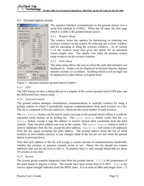
Figure 3. Operator interface ground station window<br />
The operator interface communicates to the ground station over a<br />
serial link (default to COM1). When the OI starts the first page<br />
which is visible is the ground station screen.<br />
4.3.1 Window Menu<br />
The window menu has options for minimizing or restoring any<br />
avionics windows in the <strong>system</strong>, for selecting any avionic window,<br />
and for cascading or tiling the avionics windows. As of version<br />
1.1.4 the window menu also gives the option for an advanced<br />
versus simple view. The simple view hides the primary <strong>system</strong><br />
setup windows on the avionics window.<br />
4.3.2 Units Menu<br />
The units menu allows the <strong>user</strong> to select the units that telemetry are<br />
displayed in. Angles can be displayed in decimal degrees, degrees<br />
minutes seconds, or in radians. Anything which is not an angle can<br />
be displayed in either Metric or English units.<br />
4.3.3 GPS<br />
The GPS button invokes a dialog that gives a display of the current ground station GPS data, and<br />
the differential base station setup.<br />
4.3.4 Network Control<br />
The ground station manages simultaneous communications to multiple avionics by using a<br />
polling scheme in which it periodically requests communications from each avionics in a list.<br />
The list is composed of <strong>Piccolo</strong> addresses, which are the serial number of each avionics.<br />
The Add Address button can be used to send a message to the ground station telling it to add the<br />
requested serial number to its polling list. The Pilot Address button works like the Add<br />
Address button, except it tags the address to receive manual pilot commands from the pilot<br />
console. Only one pilot address can exist in the <strong>system</strong>. The Remove Address button is used to<br />
remove addresses from the list, except the pilot address. Remove All will remove all addresses<br />
from the list, again excepting the pilot address. The ground station stores the list of serial<br />
numbers in non-volatile memory so any changes made to the list are not lost when the ground<br />
station is powered down.<br />
Note that each address in the list will occupy a certain amount of communications bandwidth,<br />
whether the avionics in question actually exists or not. Hence the list should not contain<br />
addresses that you do not wish to talk to. In practice there is only enough bandwidth for about<br />
10 avionics at one time.<br />
4.3.5 System<br />
The <strong>system</strong> group contains diagnostic data from the ground station. T[°C] is the temperature of<br />
the main board in degrees Celsius. The boards have been tested from 0 to 80°C. RSSI is the<br />
receive signal strength indicator from the MHX radio. It is in units of dBm and ranges from –71<br />
<strong>Piccolo</strong> User’s Guide Page 12


