3-Storey Library Building in Karachi A Case Study ... - NED University
3-Storey Library Building in Karachi A Case Study ... - NED University
3-Storey Library Building in Karachi A Case Study ... - NED University

Create successful ePaper yourself
Turn your PDF publications into a flip-book with our unique Google optimized e-Paper software.
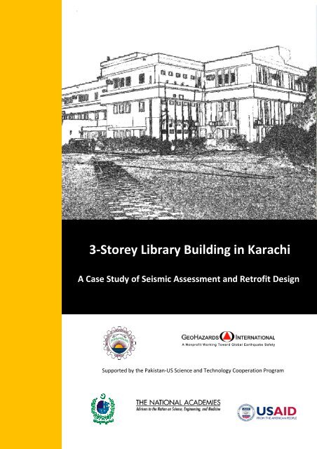
3-<strong>Storey</strong> <strong>Library</strong> <strong>Build<strong>in</strong>g</strong> <strong>in</strong> <strong>Karachi</strong><br />
A <strong>Case</strong> <strong>Study</strong> of Seismic Assessment and Retrofit Design<br />
Supported by the Pakistan-US Science and Technology Cooperation Program
3-<strong>Storey</strong> <strong>Library</strong> <strong>Build<strong>in</strong>g</strong> <strong>in</strong> <strong>Karachi</strong>: A <strong>Case</strong> <strong>Study</strong> of Seismic Assessment and Retrofit Design<br />
Summary<br />
This case study build<strong>in</strong>g is a library build<strong>in</strong>g located on a university campus <strong>in</strong> <strong>Karachi</strong>. It is a<br />
re<strong>in</strong>forced concrete framed build<strong>in</strong>g <strong>in</strong>itially consist<strong>in</strong>g of two floors with beam-slab fram<strong>in</strong>g system.<br />
Later on, a small extension was built on the front of the build<strong>in</strong>g’s ground floor, and separated from<br />
orig<strong>in</strong>al build<strong>in</strong>g by expansion jo<strong>in</strong>ts. Recently, a new floor and a detached external emergency exit<br />
stair case at rear of the build<strong>in</strong>g have been added. The build<strong>in</strong>g was constructed before the 2005<br />
Kashmir Earthquake. Project participants selected this build<strong>in</strong>g as a case study because it has several<br />
seismic vulnerabilities common to low-rise build<strong>in</strong>gs <strong>in</strong> <strong>Karachi</strong>: a weak story created by open<br />
work<strong>in</strong>g area at the ground floor, an eccentrically located stair case, a heavy rooftop water tank, and<br />
heavy, stiff unre<strong>in</strong>forced masonry <strong>in</strong>fill walls that were not considered dur<strong>in</strong>g the structural design of<br />
the build<strong>in</strong>g.<br />
The case study team assessed the build<strong>in</strong>g’s potential seismic vulnerabilities us<strong>in</strong>g the US Federal<br />
Emergency Management Agency (FEMA) Prestandard 310 Tier 1 Checklist modified for Pakistan<br />
conditions, as well as the American Society of Civil Eng<strong>in</strong>eers (ASCE) Standard 31 Tier 2 and 3<br />
analyses and acceptance and model<strong>in</strong>g criteria from ASCE 41. The build<strong>in</strong>g was found to be<br />
<strong>in</strong>adequate for Seismic Zone 4 and requires retrofitt<strong>in</strong>g to <strong>in</strong>crease the stiffness and stability of the<br />
build<strong>in</strong>g.<br />
The team exam<strong>in</strong>ed several retrofit schemes consist<strong>in</strong>g of comb<strong>in</strong>ations of re<strong>in</strong>forced <strong>in</strong>fill panels<br />
and column jacket<strong>in</strong>g, and selected a retrofit solution consist<strong>in</strong>g solely of re<strong>in</strong>forced <strong>in</strong>fill panels.<br />
2
3-<strong>Storey</strong> <strong>Library</strong> <strong>Build<strong>in</strong>g</strong> <strong>in</strong> <strong>Karachi</strong>: A <strong>Case</strong> <strong>Study</strong> of Seismic Assessment and Retrofit Design<br />
About the Project<br />
<strong>NED</strong> <strong>University</strong> of Eng<strong>in</strong>eer<strong>in</strong>g (<strong>NED</strong>) and Technology and GeoHazards International (GHI), a<br />
California based non-profit organization that improves global earthquake safety, are work<strong>in</strong>g to build<br />
capacity <strong>in</strong> Pakistan's academic, public, and private sectors to assess and reduce the seismic<br />
vulnerability of exist<strong>in</strong>g build<strong>in</strong>gs, and to construct new build<strong>in</strong>gs better. The project is part of the<br />
Pakistan-US Science and Technology Cooperation Program, which is funded by the Pakistan Higher<br />
Education Commission (HEC) and the National Academies through a grant from the United States<br />
Agency for International Development (USAID). Together, the <strong>NED</strong> and GHI project teams are<br />
assess<strong>in</strong>g and design<strong>in</strong>g seismic retrofits for exist<strong>in</strong>g build<strong>in</strong>gs typical of the local build<strong>in</strong>g stock, such<br />
as the one described <strong>in</strong> this report, <strong>in</strong> order to provide case studies for use <strong>in</strong> teach<strong>in</strong>g students and<br />
professionals how to address the earthquake risks posed by exist<strong>in</strong>g build<strong>in</strong>g. The teams are also<br />
improv<strong>in</strong>g the earthquake eng<strong>in</strong>eer<strong>in</strong>g curriculum, provid<strong>in</strong>g professional tra<strong>in</strong><strong>in</strong>g for Pakistani<br />
eng<strong>in</strong>eers, and strengthen<strong>in</strong>g cooperative research and professional relationships between Pakistani<br />
and American researchers.<br />
<strong>Case</strong> <strong>Study</strong> Participants<br />
This report was compiled by Dr. Rashid Khan, Associate Professor, Department of Civil Eng<strong>in</strong>eer<strong>in</strong>g,<br />
<strong>NED</strong> <strong>University</strong> of Eng<strong>in</strong>eer<strong>in</strong>g and Technology, and Dr. Janise Rodgers, Project Manager,<br />
GeoHazards International.<br />
This case study build<strong>in</strong>g was <strong>in</strong>vestigated by Mr. Aslam Faqeer Mohammad, Assistant Professor,<br />
Department of Civil Eng<strong>in</strong>eer<strong>in</strong>g, <strong>NED</strong> <strong>University</strong> of Eng<strong>in</strong>eer<strong>in</strong>g and Technology, Ms. Najmus Sahar<br />
Zafar, Assistant Professor, Department of Civil Eng<strong>in</strong>eer<strong>in</strong>g, <strong>NED</strong> <strong>University</strong> of Eng<strong>in</strong>eer<strong>in</strong>g and<br />
Technology, and Ms. Nighat Fatima, Senior Structural Eng<strong>in</strong>eer, NESPAK.<br />
The case study team and authors wish to express their gratitude for the technical guidance provided<br />
by Dr. Gregory G. Deierle<strong>in</strong>, Professor, Department of Civil and Environmental Eng<strong>in</strong>eer<strong>in</strong>g, Stanford<br />
<strong>University</strong>; Dr. S.F.A. Rafeeqi, Pro Vice Chancellor, <strong>NED</strong> <strong>University</strong> of Eng<strong>in</strong>eer<strong>in</strong>g and Technology; Dr.<br />
Khalid M. Mosalam, Professor and Vice-Chair, Department of Civil and Environmental Eng<strong>in</strong>eer<strong>in</strong>g,<br />
<strong>University</strong> of California, Berkeley; Dr. Sarosh H. Lodi, Professor and Dean, Faculty of Eng<strong>in</strong>eer<strong>in</strong>g and<br />
Architecture, <strong>NED</strong> <strong>University</strong> Eng<strong>in</strong>eer<strong>in</strong>g and Technology; Dr. Selim Gunay, Post-doctoral<br />
Researcher, Department of Civil and Environmental Eng<strong>in</strong>eer<strong>in</strong>g, <strong>University</strong> of California, Berkeley;<br />
Mr. David Mar, Pr<strong>in</strong>cipal and Lead Designer, Tipp<strong>in</strong>g Mar, and Mr. L. Thomas Tob<strong>in</strong>, Senior Advisor,<br />
GeoHazards International.<br />
3
3-<strong>Storey</strong> <strong>Library</strong> <strong>Build<strong>in</strong>g</strong> <strong>in</strong> <strong>Karachi</strong>: A <strong>Case</strong> <strong>Study</strong> of Seismic Assessment and Retrofit Design<br />
Contents<br />
Summary........................................................................................................................................... 2<br />
<strong>Case</strong> <strong>Study</strong> Participants ..................................................................................................................... 3<br />
Introduction ...................................................................................................................................... 5<br />
<strong>Build<strong>in</strong>g</strong> Information.......................................................................................................................... 5<br />
Site Information ................................................................................................................................ 8<br />
Hazard Information ........................................................................................................................... 8<br />
Initial and L<strong>in</strong>ear Evaluations of Exist<strong>in</strong>g <strong>Build<strong>in</strong>g</strong>............................................................................... 9<br />
Checklist-based Evaluation ............................................................................................................ 9<br />
L<strong>in</strong>ear Evaluation........................................................................................................................... 9<br />
Detailed Evaluations of Exist<strong>in</strong>g <strong>Build<strong>in</strong>g</strong>.......................................................................................... 11<br />
Analytical Models ........................................................................................................................ 11<br />
Load<strong>in</strong>g and Performance Criteria................................................................................................ 11<br />
Analysis Results ........................................................................................................................... 12<br />
Retrofit Solution.............................................................................................................................. 15<br />
Conceptual Solutions Considered................................................................................................. 15<br />
Retrofit Analysis Results .............................................................................................................. 16<br />
Recommended Retrofit Solution...................................................................................................... 18<br />
Design and Detail<strong>in</strong>g of Retrofit Solution ..................................................................................... 18<br />
Observations and Future Work........................................................................................................ 21<br />
Appendix A: Tier 1 Checklists........................................................................................................... 22<br />
Appendix B: L<strong>in</strong>ear Analysis (Tier 2) Results ..................................................................................... 24<br />
Appendix C: Nonl<strong>in</strong>ear Analysis Results for Exist<strong>in</strong>g <strong>Build<strong>in</strong>g</strong>............................................................ 30<br />
Appendix D: Nonl<strong>in</strong>ear Analysis (Tier 3) Results for Selected Retrofit Solution ................................. 36<br />
Appendix E: Retrofit Draw<strong>in</strong>gs ......................................................................................................... 41<br />
4
3-<strong>Storey</strong> <strong>Library</strong> <strong>Build<strong>in</strong>g</strong> <strong>in</strong> <strong>Karachi</strong>: A <strong>Case</strong> <strong>Study</strong> of Seismic Assessment and Retrofit Design<br />
Introduction<br />
The team used the US Federal Emergency Management Agency (FEMA) Prestandard 310 Tier 1<br />
Checklist modified for Pakistan conditions, as well as the American Society of Civil Eng<strong>in</strong>eers (ASCE)<br />
Standard 31-03 Tier 2 and 3 analyses and acceptance and model<strong>in</strong>g criteria from ASCE 41-06 and<br />
other documents. The Tier 1 vulnerability assessment exercise carried out provided an opportunity<br />
to evaluate a real build<strong>in</strong>g <strong>in</strong> the field. On the basis of the vulnerabilities found through the Tier 1<br />
assessment, Tier 2 (l<strong>in</strong>ear static structural analysis) and Tier 3 (nonl<strong>in</strong>ear static structural analysis)<br />
assessments were carried out to assess the vulnerabilities and potential solutions <strong>in</strong> more detail.<br />
<strong>Case</strong> study team members used structural analysis software ETABS from Computers and Structures,<br />
Inc. of Berkeley, California to perform the l<strong>in</strong>ear and nonl<strong>in</strong>ear analyses.<br />
<strong>Build<strong>in</strong>g</strong> Information<br />
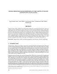
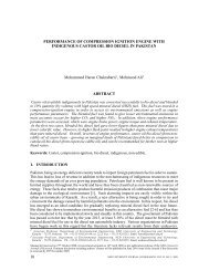
The build<strong>in</strong>g, shown <strong>in</strong> Figure 1, is a three storey (ground plus two) library build<strong>in</strong>g. The build<strong>in</strong>g’s<br />
overall dimensions are 109’-6” by 141’-0”, and it is approximately 42 feet tall. The build<strong>in</strong>g has a<br />
re<strong>in</strong>forced concrete moment frame structural system with unre<strong>in</strong>forced concrete block <strong>in</strong>fill walls.<br />
The concrete block <strong>in</strong>fill walls are 6 <strong>in</strong>ches thick and located primarily at the periphery. The<br />
foundations are re<strong>in</strong>forced concrete spread foot<strong>in</strong>gs. The build<strong>in</strong>g is relatively new and is <strong>in</strong><br />
reasonably good condition. No condition assessments or repairs have been made.<br />
Figure 1. Front elevation view of the build<strong>in</strong>g<br />
5
3-<strong>Storey</strong> <strong>Library</strong> <strong>Build<strong>in</strong>g</strong> <strong>in</strong> <strong>Karachi</strong>: A <strong>Case</strong> <strong>Study</strong> of Seismic Assessment and Retrofit Design<br />
The architectural and structural draw<strong>in</strong>gs are shown <strong>in</strong> Figure 2 to Figure 4. Concrete of fc’=3000psi<br />
and steel of fy=60000 psi are used. The typical beam size is 8”x24” and column size is 20”x20”. The<br />
slabs are 6” thick. Orig<strong>in</strong>al design calculations are not available but ACI-99 was used to design the<br />
frame elements and earthquake analysis may have been carried out us<strong>in</strong>g UBC-97.<br />
Figure 2. Architectural plans of ground floor and first floor<br />
6
3-<strong>Storey</strong> <strong>Library</strong> <strong>Build<strong>in</strong>g</strong> <strong>in</strong> <strong>Karachi</strong>: A <strong>Case</strong> <strong>Study</strong> of Seismic Assessment and Retrofit Design<br />
Figure 3. Architectural plans of second floor and roof<br />
After the ma<strong>in</strong> build<strong>in</strong>g was constructed, the second storey was added, an emergency exit stair was<br />
constructed at the rear corner, and a small s<strong>in</strong>gle storey additional block was built near the ma<strong>in</strong><br />
7
3-<strong>Storey</strong> <strong>Library</strong> <strong>Build<strong>in</strong>g</strong> <strong>in</strong> <strong>Karachi</strong>: A <strong>Case</strong> <strong>Study</strong> of Seismic Assessment and Retrofit Design<br />
entrance as <strong>in</strong>dicated by the black outl<strong>in</strong>es <strong>in</strong> the architectural plans above. The emergency exit stair<br />
and s<strong>in</strong>gle storey additional block are separated from the ma<strong>in</strong> build<strong>in</strong>g by a small expansion jo<strong>in</strong>t<br />
that was not designed to accommodate seismic deformations.<br />
Figure 4. Structural re<strong>in</strong>forcement for roof slab <strong>in</strong> plan<br />
Site Information<br />
The build<strong>in</strong>g is located <strong>in</strong> an area with firm soil, where bedrock outcrops are often found close to the<br />
surface. No known active faults pass through or near the site. The bear<strong>in</strong>g capacity of the soil is 2.0<br />
tons per square foot (tsf).<br />
Hazard Information<br />
<strong>Karachi</strong>’s current seismic zon<strong>in</strong>g under the National <strong>Build<strong>in</strong>g</strong> Code of Pakistan is Zone 2B. However,<br />
there is currently significant uncerta<strong>in</strong>ty regard<strong>in</strong>g the severity of the city’s seismic hazard. For this<br />
reason, the build<strong>in</strong>g is be<strong>in</strong>g evaluated for Zone 4 of the 1997 Uniform <strong>Build<strong>in</strong>g</strong> Code with seismic<br />
coefficients C a =0.4, C v =0.4. The site is not located near any known active faults so near-source<br />
factors are not applicable.<br />
8
3-<strong>Storey</strong> <strong>Library</strong> <strong>Build<strong>in</strong>g</strong> <strong>in</strong> <strong>Karachi</strong>: A <strong>Case</strong> <strong>Study</strong> of Seismic Assessment and Retrofit Design<br />
Initial and L<strong>in</strong>ear Evaluations of Exist<strong>in</strong>g <strong>Build<strong>in</strong>g</strong><br />
Checklist-based Evaluation<br />
The build<strong>in</strong>g was assessed us<strong>in</strong>g a version of the FEMA 310 Tier 1 Checklist modified for Pakistan<br />
conditions. This Tier 1 assessment <strong>in</strong>dicated a number of non-compliant items (i.e., deficiencies) <strong>in</strong><br />
the build<strong>in</strong>g, which are summarized <strong>in</strong> the follow<strong>in</strong>g table:<br />
Checklist<br />
<strong>Build<strong>in</strong>g</strong> System<br />
Lateral Force-resist<strong>in</strong>g System<br />
Geologic Hazards and Foundation<br />
Non-compliant Items<br />
Soft storey<br />
Mass irregularity<br />
Drift<br />
Interfer<strong>in</strong>g wall<br />
Shear stress check<br />
Axial stress check<br />
None<br />
L<strong>in</strong>ear Evaluation<br />
Figure 5 shows the 3-D model of the build<strong>in</strong>g generated <strong>in</strong> ETABS Nonl<strong>in</strong>ear version 9.7.0. The beams<br />
and columns were modeled with l<strong>in</strong>ear beam-column elements, and the <strong>in</strong>fill walls were modeled<br />
with s<strong>in</strong>gle l<strong>in</strong>ear compression struts. The l<strong>in</strong>ear static analysis shows that there are a number of<br />
columns with demand/capacity ratios (DCRs) greater than one and even exceed global ductility of<br />
two, so the build<strong>in</strong>g is expected to respond <strong>in</strong> the nonl<strong>in</strong>ear range. Please see Appendix B for l<strong>in</strong>ear<br />
analysis and Appendix C for non l<strong>in</strong>ear analysis results.<br />
Figure 5. Render<strong>in</strong>g of l<strong>in</strong>ear ETABS model of the build<strong>in</strong>g<br />
9
3-<strong>Storey</strong> <strong>Library</strong> <strong>Build<strong>in</strong>g</strong> <strong>in</strong> <strong>Karachi</strong>: A <strong>Case</strong> <strong>Study</strong> of Seismic Assessment and Retrofit Design<br />
The team also conducted the other checks mandated <strong>in</strong> ASCE 31 for Tier 2 analysis based on the Tier<br />
1 Checklist results. Despite us<strong>in</strong>g a modified FEMA 310 Tier 1 Checklist there was enough<br />
correspondence between items <strong>in</strong> the ASCE 31 Tier 1 Checklist and the modified FEMA 310 checklist<br />
to use ASCE 31’s Tier 2 checks directly. For this build<strong>in</strong>g, the required Tier 2 checks were for torsion<br />
irregularity (shown <strong>in</strong> Table 1), mass irregularity (shown <strong>in</strong> Table 2), storey drift (shown <strong>in</strong> Table 3)<br />
and soft storey (shown <strong>in</strong> Table 4).<br />
Table 1. Torsion irregularity check<br />
XCM = centre of mass <strong>in</strong> X direction, YCM = centre of mass <strong>in</strong> Y direction, XCR = centre of rigidity <strong>in</strong> X direction,<br />
YCR = centre of rigidity <strong>in</strong> Y direction<br />
Table 1 shows that there is no torsion irregularity per ASCE 31, because the difference between<br />
centre of mass and centre of rigidity is less than 20% for each storey.<br />
Table 2. Mass Irregularity<br />
Table 2 shows that the build<strong>in</strong>g has mass irregularity at ground floor level.<br />
Table 3. <strong>Storey</strong> drift check<br />
Table 3 shows that the build<strong>in</strong>g exceeds the allowable storey drift value of 0.02 <strong>in</strong> the y direction at<br />
first floor level.<br />
10
3-<strong>Storey</strong> <strong>Library</strong> <strong>Build<strong>in</strong>g</strong> <strong>in</strong> <strong>Karachi</strong>: A <strong>Case</strong> <strong>Study</strong> of Seismic Assessment and Retrofit Design<br />
Table 4. Soft storey check<br />
Table 4 shows that the build<strong>in</strong>g has soft storey at ground floor level both <strong>in</strong> x and y directions.<br />
Detailed Evaluations of Exist<strong>in</strong>g <strong>Build<strong>in</strong>g</strong><br />
Through l<strong>in</strong>ear static analysis of this build<strong>in</strong>g, the checks for build<strong>in</strong>g system (mass irregularities,<br />
torsion etc.) <strong>in</strong> tier 1 analysis which were assumed non-compliant through visual <strong>in</strong>spection were<br />
confirmed by tier 2 analysis results. In addition it was also observed that many columns had DCR > 2.<br />
This required further non l<strong>in</strong>ear static analysis. The Pushover static analysis based on performancebased<br />
seismic design was adopted and h<strong>in</strong>ge properties accord<strong>in</strong>g to ATC-40 and ASCE 41-06 criteria<br />
are evaluated and manually entered <strong>in</strong>to the 3-D model.<br />
Analytical Models<br />
The build<strong>in</strong>g was modeled us<strong>in</strong>g discrete plastic h<strong>in</strong>ge elements (i.e., a lumped plasticity model) <strong>in</strong><br />
locations expected to experience nonl<strong>in</strong>ear behavior, such as beam and column ends and the<br />
midpo<strong>in</strong>t of compression struts. ASCE/SEI 41-06, Seismic Rehabilitation of Exist<strong>in</strong>g <strong>Build<strong>in</strong>g</strong>s, was<br />
adopted to compute the plastic h<strong>in</strong>ge values for compressive struts, beams and columns. Infill walls<br />
were modeled us<strong>in</strong>g equivalent compression struts def<strong>in</strong>ed us<strong>in</strong>g procedure <strong>in</strong> Section 7.5.2 of FEMA<br />
356. The h<strong>in</strong>ge properties for compression struts were computed us<strong>in</strong>g lower bound unre<strong>in</strong>forced<br />
masonry properties given <strong>in</strong> table 7-1 (ASCE/SEI 41-06). For evaluation of plastic h<strong>in</strong>ges for beams<br />
and columns, values given <strong>in</strong> table 6-7 and table 6-8 (Supplement 1 for ASCE/SEI 41-06) were used,<br />
respectively. ETABS Nonl<strong>in</strong>ear (version 9.7.0) was used to create the models and perform the<br />
pushover analysis. Table 5 gives the geometric and material properties used <strong>in</strong> the model.<br />
Load<strong>in</strong>g and Performance Criteria<br />
Table 5 shows the ETABS <strong>in</strong>put values for gravity and earthquake load<strong>in</strong>g, as well as key<br />
assumptions. The UBC-97 was used for the seismic demands. As mentioned <strong>in</strong> the Seismic Hazard<br />
section, the build<strong>in</strong>g was evaluated for Zone 4 seismic loads due to the current uncerta<strong>in</strong>ty <strong>in</strong> the<br />
11
3-<strong>Storey</strong> <strong>Library</strong> <strong>Build<strong>in</strong>g</strong> <strong>in</strong> <strong>Karachi</strong>: A <strong>Case</strong> <strong>Study</strong> of Seismic Assessment and Retrofit Design<br />
seismic hazard. For the pushover analysis, the team used restart us<strong>in</strong>g secant stiffness for member<br />
unload<strong>in</strong>g method with P-Delta effects for geometric nonl<strong>in</strong>earity. A life safety performance criterion<br />
was selected for the study build<strong>in</strong>g.<br />
Table 5. Loads and modell<strong>in</strong>g parameters<br />
Loads:<br />
Dead load<br />
Live load<br />
Earthquake load:<br />
Z<br />
R<br />
C a<br />
C v<br />
Soil type<br />
Slab loads transferred to beam were manually calculated and<br />
applied to each of the beams <strong>in</strong> the 3-D model.<br />
Self wt of frame + 6” thick slab + 2” thick f<strong>in</strong>ishes + 50psf wall load<br />
100psf on floor and 30psf on roof<br />
0.4g<br />
5.5<br />
0.4N a (Ref: Table 16-Q (UBC 97)) N a = 1.0<br />
0.4N v (Ref: Table 16-R (UBC 97) N v = 1.0<br />
S B (Ref: Table 16-J UBC-97)<br />
Geometric properties Typical Beam size Width = 12<br />
Depth = 24<br />
Typical Column size<br />
Width = 20 <strong>in</strong><br />
Depth = 20 <strong>in</strong><br />
Height = 12 ft<br />
Ord<strong>in</strong>ary Strut<br />
Width = 6<strong>in</strong><br />
(for model<strong>in</strong>g <strong>in</strong>fill)<br />
Depth = 30 <strong>in</strong><br />
Material properties<br />
f’c = 3000 psi for beam and column<br />
fc’ = 300 psi for concrete block <strong>in</strong>fill ord<strong>in</strong>ary strut<br />
E con = 3144 ksi for beam and column<br />
E mas = 214.5 ksi<br />
Analysis Results<br />
Figure 6 shows the pushover load-deformation curve. The curve bends and becomes jagged as the<br />
various structural members beg<strong>in</strong> to yield and undergo plastic deformation. In Figure 7, the<br />
pushover curve, a measure of the build<strong>in</strong>g’s capacity, is converted <strong>in</strong>to a capacity spectrum and<br />
compared with the estimated demand us<strong>in</strong>g the capacity spectrum method. This figure shows the<br />
performance level where demand and capacity spectra <strong>in</strong>tersect each other at that po<strong>in</strong>t where it is<br />
necessary to see the condition of the structure, and whether it is fulfill<strong>in</strong>g the demand or not. This<br />
po<strong>in</strong>t is called the performance po<strong>in</strong>t.<br />
12
3-<strong>Storey</strong> <strong>Library</strong> <strong>Build<strong>in</strong>g</strong> <strong>in</strong> <strong>Karachi</strong>: A <strong>Case</strong> <strong>Study</strong> of Seismic Assessment and Retrofit Design<br />
Figure 6. Pushover load-deformation curve<br />
Figure 7. Performance level<br />
13
3-<strong>Storey</strong> <strong>Library</strong> <strong>Build<strong>in</strong>g</strong> <strong>in</strong> <strong>Karachi</strong>: A <strong>Case</strong> <strong>Study</strong> of Seismic Assessment and Retrofit Design<br />
Figure 8 shows the force deformation relation for the plastic h<strong>in</strong>ges, and shows how the acceptance<br />
criteria and Immediate Occupancy, Life Safety and Collapse Prevention performance states are<br />
def<strong>in</strong>ed. Other po<strong>in</strong>ts on the curve represent behavior states: B means yield<strong>in</strong>g has occurred, C is<br />
po<strong>in</strong>t just before major strength loss, D is the po<strong>in</strong>t just after major strength loss, and E represents<br />
complete failure. Figure 9 shows the state of some of the nonl<strong>in</strong>ear plastic h<strong>in</strong>ges compared to the<br />
acceptance criteria at the performance po<strong>in</strong>t. The plot at the left of Figure 9 has a legend with the<br />
colors at the bottom. In these plots, B, IO, LS, CP, C, D, and E correspond to po<strong>in</strong>ts on the forcedeformation<br />
curve for the h<strong>in</strong>ge shown <strong>in</strong> Figure 8. Appendix C conta<strong>in</strong>s the rema<strong>in</strong><strong>in</strong>g pushover<br />
analysis results for the exist<strong>in</strong>g build<strong>in</strong>g.<br />
Figure 8. Force-deformation curve for h<strong>in</strong>ges (repr<strong>in</strong>ted from FEMA 356, the precursor to ASCE/SEI 41-06)<br />
show<strong>in</strong>g the def<strong>in</strong>ition of acceptance criteria and performance states<br />
Figure 9. H<strong>in</strong>ge deformation vs. acceptance criteria<br />
14
3-<strong>Storey</strong> <strong>Library</strong> <strong>Build<strong>in</strong>g</strong> <strong>in</strong> <strong>Karachi</strong>: A <strong>Case</strong> <strong>Study</strong> of Seismic Assessment and Retrofit Design<br />
The columns <strong>in</strong> the small s<strong>in</strong>gle storey addition at the front of the library are fail<strong>in</strong>g, as <strong>in</strong>dicated by<br />
the red circles <strong>in</strong> Figure 9. This shows that retrofitt<strong>in</strong>g is needed to achieve stability and to achieve<br />
the desired life safety performance level.<br />
Retrofit Solution<br />
Conceptual Solutions Considered<br />
In order to prevent column failure <strong>in</strong> the small additional block and to prevent pound<strong>in</strong>g with the<br />
ma<strong>in</strong> build<strong>in</strong>g, the case study team decided to stitch the small additional block and the emergency<br />
exit stair to the ma<strong>in</strong> build<strong>in</strong>g. They also considered re<strong>in</strong>forced two options for add<strong>in</strong>g deformation<br />
capacity and strength <strong>in</strong> the ground storey: <strong>in</strong>fill panels re<strong>in</strong>forced by a shotcrete to create a shear<br />
wall, and a comb<strong>in</strong>ation of re<strong>in</strong>forced <strong>in</strong>fill panels and wrapped columns. The team determ<strong>in</strong>ed that<br />
a walls-only solution was preferable, and then <strong>in</strong>vestigated two configurations of re<strong>in</strong>forced <strong>in</strong>fill<br />
panels. The first option had re<strong>in</strong>forced panels <strong>in</strong> the ground storey only, and not below ground. The<br />
second and preferred option, shown <strong>in</strong> Figure 10, placed panels <strong>in</strong> more optimal locations for<br />
constructability and also provided panels below the ground level, <strong>in</strong> between the base and ground<br />
floor at the outer periphery.<br />
Figure 10. Retrofit option 2 (selected retrofit solution)<br />
15
3-<strong>Storey</strong> <strong>Library</strong> <strong>Build<strong>in</strong>g</strong> <strong>in</strong> <strong>Karachi</strong>: A <strong>Case</strong> <strong>Study</strong> of Seismic Assessment and Retrofit Design<br />
Retrofit Analysis Results<br />
Figure 11 shows a comparison of pushover analysis results for the two retrofit options versus the<br />
exist<strong>in</strong>g build<strong>in</strong>g. The capacity and demand spectra for retrofit option 2 are shown <strong>in</strong> Figure 12.<br />
Retrofit option 2 provides better performance than option 1, and rectifies the column failures<br />
experienced by the exist<strong>in</strong>g build<strong>in</strong>g, as Figure 13 shows.<br />
Figure 11. Comparison of pushover curves; Retrofitted model #01 is Option 1, Retrofitted model #02 is<br />
Option 2<br />
16
3-<strong>Storey</strong> <strong>Library</strong> <strong>Build<strong>in</strong>g</strong> <strong>in</strong> <strong>Karachi</strong>: A <strong>Case</strong> <strong>Study</strong> of Seismic Assessment and Retrofit Design<br />
Figure 12. Performance level for retrofitted build<strong>in</strong>g<br />
Figure 13. H<strong>in</strong>ge deformation vs. acceptance criteria before retrofit (left) after retrofit (right)<br />
17
3-<strong>Storey</strong> <strong>Library</strong> <strong>Build<strong>in</strong>g</strong> <strong>in</strong> <strong>Karachi</strong>: A <strong>Case</strong> <strong>Study</strong> of Seismic Assessment and Retrofit Design<br />
Recommended Retrofit Solution<br />
The case study team selected option 2, shown <strong>in</strong> Figure 10, as the recommended retrofit solution. It<br />
is simpler to construct than option 1 because it does not require construction near the toilets which<br />
would have been difficult due to the plumb<strong>in</strong>g and fixtures.<br />
Design and Detail<strong>in</strong>g of Retrofit Solution<br />
Eng<strong>in</strong>eer<strong>in</strong>g draw<strong>in</strong>gs conta<strong>in</strong><strong>in</strong>g selected details of the retrofit solution are shown below. Appendix<br />
E conta<strong>in</strong>s the full set of retrofit draw<strong>in</strong>gs. Figure 14 shows the locations of the re<strong>in</strong>forced <strong>in</strong>fill panels<br />
<strong>in</strong> plan, and Figure 15 shows details of the re<strong>in</strong>forced <strong>in</strong>fill panels. New tie beams were provided<br />
beneath the re<strong>in</strong>forced panels; Figure 16 shows a typical detail. Stitch<strong>in</strong>g between the build<strong>in</strong>gs was<br />
accomplished by attach<strong>in</strong>g tie plates with drilled anchor bolts across the jo<strong>in</strong>t. A through-bolt detail,<br />
where holes are drilled through the beams just below the slab us<strong>in</strong>g large plate washers to secure<br />
the through-bolts (anchor rods) on either side of the beam, was used to ensure that the anchor rods<br />
are strong enough. Figure 17 shows the stitch<strong>in</strong>g details.<br />
Figure 14. Locations of retrofitted <strong>in</strong>fill walls <strong>in</strong> plan<br />
18
3-<strong>Storey</strong> <strong>Library</strong> <strong>Build<strong>in</strong>g</strong> <strong>in</strong> <strong>Karachi</strong>: A <strong>Case</strong> <strong>Study</strong> of Seismic Assessment and Retrofit Design<br />
Figure 15. Detail for strengthened <strong>in</strong>fill panels<br />
19
3-<strong>Storey</strong> <strong>Library</strong> <strong>Build<strong>in</strong>g</strong> <strong>in</strong> <strong>Karachi</strong>: A <strong>Case</strong> <strong>Study</strong> of Seismic Assessment and Retrofit Design<br />
Figure 16. Detail for new tie beam<br />
Figure 17. Details for stitch<strong>in</strong>g<br />
20
3-<strong>Storey</strong> <strong>Library</strong> <strong>Build<strong>in</strong>g</strong> <strong>in</strong> <strong>Karachi</strong>: A <strong>Case</strong> <strong>Study</strong> of Seismic Assessment and Retrofit Design<br />
Observations and Future Work<br />
In this build<strong>in</strong>g, the <strong>in</strong>fill walls were located at the periphery of the build<strong>in</strong>g and did not contribute as<br />
significantly to the build<strong>in</strong>g behavior as <strong>in</strong> other build<strong>in</strong>gs <strong>in</strong>vestigated dur<strong>in</strong>g the project. Also, the<br />
retrofit solution was strongly <strong>in</strong>fluenced by architectural and functional considerations. The lack of<br />
<strong>in</strong>fill walls and the large number of w<strong>in</strong>dows necessitated careful selection of locations for<br />
re<strong>in</strong>forced <strong>in</strong>fill panels.<br />
21
3-<strong>Storey</strong> <strong>Library</strong> <strong>Build<strong>in</strong>g</strong> <strong>in</strong> <strong>Karachi</strong>: A <strong>Case</strong> <strong>Study</strong> of Seismic Assessment and Retrofit Design<br />
Appendix A: Tier 1 Checklists<br />
22
3-<strong>Storey</strong> <strong>Library</strong> <strong>Build<strong>in</strong>g</strong> <strong>in</strong> <strong>Karachi</strong>: A <strong>Case</strong> <strong>Study</strong> of Seismic Assessment and Retrofit Design<br />
23
3-<strong>Storey</strong> <strong>Library</strong> <strong>Build<strong>in</strong>g</strong> <strong>in</strong> <strong>Karachi</strong>: A <strong>Case</strong> <strong>Study</strong> of Seismic Assessment and Retrofit Design<br />
Appendix B: L<strong>in</strong>ear Analysis (Tier 2) Results<br />
Demand/Capacity Ratios for Frame at Grid-1<br />
Demand/Capacity Ratios for Frame at Grid-2<br />
24
3-<strong>Storey</strong> <strong>Library</strong> <strong>Build<strong>in</strong>g</strong> <strong>in</strong> <strong>Karachi</strong>: A <strong>Case</strong> <strong>Study</strong> of Seismic Assessment and Retrofit Design<br />
Demand/Capacity Ratios for Frame at Grid-2a<br />
Demand/Capacity Ratios for Frame at Grid-3<br />
25
3-<strong>Storey</strong> <strong>Library</strong> <strong>Build<strong>in</strong>g</strong> <strong>in</strong> <strong>Karachi</strong>: A <strong>Case</strong> <strong>Study</strong> of Seismic Assessment and Retrofit Design<br />
Demand/Capacity Ratios for Frame at Grid-4<br />
Demand/Capacity Ratios for Frame at Grid-5<br />
26
3-<strong>Storey</strong> <strong>Library</strong> <strong>Build<strong>in</strong>g</strong> <strong>in</strong> <strong>Karachi</strong>: A <strong>Case</strong> <strong>Study</strong> of Seismic Assessment and Retrofit Design<br />
Demand/Capacity Ratios for Frame at Grid-6<br />
Demand/Capacity Ratios for Frame at Grid-7<br />
27
3-<strong>Storey</strong> <strong>Library</strong> <strong>Build<strong>in</strong>g</strong> <strong>in</strong> <strong>Karachi</strong>: A <strong>Case</strong> <strong>Study</strong> of Seismic Assessment and Retrofit Design<br />
Demand/Capacity Ratios for Frame at Grid-8<br />
Demand/Capacity Ratios for Frame at Grid-9<br />
28
3-<strong>Storey</strong> <strong>Library</strong> <strong>Build<strong>in</strong>g</strong> <strong>in</strong> <strong>Karachi</strong>: A <strong>Case</strong> <strong>Study</strong> of Seismic Assessment and Retrofit Design<br />
Demand/Capacity Ratios for Beams<br />
At First Floor Level:<br />
Required re<strong>in</strong>forcement at support = 2.82 <strong>in</strong>2<br />
Required re<strong>in</strong>forcement at mid span = 1.71 <strong>in</strong>2<br />
Provided re<strong>in</strong>forcement at support = 1.5 <strong>in</strong>2<br />
Provided re<strong>in</strong>forcement at mid span = 1.5 <strong>in</strong>2<br />
Demand capacity ratio at support = 2.82/1.5 = 1.88<br />
Demand capacity ratio at support = 1.71/1.5 = 1.14<br />
29
3-<strong>Storey</strong> <strong>Library</strong> <strong>Build<strong>in</strong>g</strong> <strong>in</strong> <strong>Karachi</strong>: A <strong>Case</strong> <strong>Study</strong> of Seismic Assessment and Retrofit Design<br />
Appendix C: Nonl<strong>in</strong>ear Analysis Results for Exist<strong>in</strong>g <strong>Build<strong>in</strong>g</strong><br />
This appendix conta<strong>in</strong>s plots of the deformed shapes at the performance po<strong>in</strong>t. The state of the<br />
h<strong>in</strong>ges versus the acceptance criteria are <strong>in</strong>dicated by the colour of the circles. In these plots, B, IO,<br />
LS, CP, C, D, and E correspond to po<strong>in</strong>ts on the backbone curve for the h<strong>in</strong>ge that represent certa<strong>in</strong><br />
performance levels or behavior states <strong>in</strong> ASCE 41-06, as def<strong>in</strong>ed <strong>in</strong> Figure 8.<br />
Mechanism or Deformed shapes at Performance Po<strong>in</strong>t for grid-1<br />
30
3-<strong>Storey</strong> <strong>Library</strong> <strong>Build<strong>in</strong>g</strong> <strong>in</strong> <strong>Karachi</strong>: A <strong>Case</strong> <strong>Study</strong> of Seismic Assessment and Retrofit Design<br />
Mechanism or Deformed shapes at Performance Po<strong>in</strong>t for grid-2<br />
Mechanism or Deformed shapes at Performance Po<strong>in</strong>t for grid-2a<br />
31
3-<strong>Storey</strong> <strong>Library</strong> <strong>Build<strong>in</strong>g</strong> <strong>in</strong> <strong>Karachi</strong>: A <strong>Case</strong> <strong>Study</strong> of Seismic Assessment and Retrofit Design<br />
Mechanism or Deformed shapes at Performance Po<strong>in</strong>t for grid-3<br />
Mechanism or Deformed shapes at Performance Po<strong>in</strong>t for grid-4<br />
32
3-<strong>Storey</strong> <strong>Library</strong> <strong>Build<strong>in</strong>g</strong> <strong>in</strong> <strong>Karachi</strong>: A <strong>Case</strong> <strong>Study</strong> of Seismic Assessment and Retrofit Design<br />
Mechanism or Deformed shapes at Performance Po<strong>in</strong>t for grid-5<br />
Mechanism or Deformed shapes at Performance Po<strong>in</strong>t for grid-6<br />
33
3-<strong>Storey</strong> <strong>Library</strong> <strong>Build<strong>in</strong>g</strong> <strong>in</strong> <strong>Karachi</strong>: A <strong>Case</strong> <strong>Study</strong> of Seismic Assessment and Retrofit Design<br />
Mechanism or Deformed shapes at Performance Po<strong>in</strong>t for grid-7<br />
Mechanism or Deformed shapes at Performance Po<strong>in</strong>t for grid-8<br />
34
3-<strong>Storey</strong> <strong>Library</strong> <strong>Build<strong>in</strong>g</strong> <strong>in</strong> <strong>Karachi</strong>: A <strong>Case</strong> <strong>Study</strong> of Seismic Assessment and Retrofit Design<br />
Mechanism or Deformed shapes at Performance Po<strong>in</strong>t for grid-9<br />
35
3-<strong>Storey</strong> <strong>Library</strong> <strong>Build<strong>in</strong>g</strong> <strong>in</strong> <strong>Karachi</strong>: A <strong>Case</strong> <strong>Study</strong> of Seismic Assessment and Retrofit Design<br />
Appendix D: Nonl<strong>in</strong>ear Analysis (Tier 3) Results for Selected Retrofit<br />
Solution<br />
This appendix conta<strong>in</strong>s plots of the deformed shapes at the performance po<strong>in</strong>t. The state of the<br />
h<strong>in</strong>ges versus the acceptance criteria are <strong>in</strong>dicated by the colour of the circles us<strong>in</strong>g the same format<br />
as <strong>in</strong> Appendix C.<br />
Mechanism or Deformed shapes at Performance Po<strong>in</strong>t for grid-1<br />
36
3-<strong>Storey</strong> <strong>Library</strong> <strong>Build<strong>in</strong>g</strong> <strong>in</strong> <strong>Karachi</strong>: A <strong>Case</strong> <strong>Study</strong> of Seismic Assessment and Retrofit Design<br />
Mechanism or Deformed shapes at Performance Po<strong>in</strong>t for grid-2<br />
Mechanism or Deformed shapes at Performance Po<strong>in</strong>t for grid-2a<br />
37
3-<strong>Storey</strong> <strong>Library</strong> <strong>Build<strong>in</strong>g</strong> <strong>in</strong> <strong>Karachi</strong>: A <strong>Case</strong> <strong>Study</strong> of Seismic Assessment and Retrofit Design<br />
Mechanism or Deformed shapes at Performance Po<strong>in</strong>t for grid-3<br />
Mechanism or Deformed shapes at Performance Po<strong>in</strong>t for grid-4<br />
38
3-<strong>Storey</strong> <strong>Library</strong> <strong>Build<strong>in</strong>g</strong> <strong>in</strong> <strong>Karachi</strong>: A <strong>Case</strong> <strong>Study</strong> of Seismic Assessment and Retrofit Design<br />
Mechanism or Deformed shapes at Performance Po<strong>in</strong>t for grid-5<br />
Mechanism or Deformed shapes at Performance Po<strong>in</strong>t for grid-6<br />
39
3-<strong>Storey</strong> <strong>Library</strong> <strong>Build<strong>in</strong>g</strong> <strong>in</strong> <strong>Karachi</strong>: A <strong>Case</strong> <strong>Study</strong> of Seismic Assessment and Retrofit Design<br />
Mechanism or Deformed shapes at Performance Po<strong>in</strong>t for grid-7<br />
Mechanism or Deformed shapes at Performance Po<strong>in</strong>t for grid-9<br />
40
3-<strong>Storey</strong> <strong>Library</strong> <strong>Build<strong>in</strong>g</strong> <strong>in</strong> <strong>Karachi</strong>: A <strong>Case</strong> <strong>Study</strong> of Seismic Assessment and Retrofit Design<br />
Appendix E: Retrofit Draw<strong>in</strong>gs<br />
41