corrosive species and scaling in wells at olkaria ... - Orkustofnun
corrosive species and scaling in wells at olkaria ... - Orkustofnun
corrosive species and scaling in wells at olkaria ... - Orkustofnun

You also want an ePaper? Increase the reach of your titles
YUMPU automatically turns print PDFs into web optimized ePapers that Google loves.
pH on adiab<strong>at</strong>ic steam loss<br />
10<br />
9<br />
8<br />
7<br />
6<br />
5<br />
OW-901 Olkaria Domes<br />
OW-301 Olkaria West<br />
OW-306 Olkaria West<br />
OW-20 Olkaria East<br />
OW-30 Olkaria East<br />
OW-714 Olkaria North East<br />
OW-34 Olkaria East<br />
OW-709 Olkaria North East<br />
OW-304D Olkaria West<br />
SV-05 Svartsengi<br />
SV-11 Svartsengi<br />
RN-10 Reykjanes<br />
RN-11 Reykjanes<br />
NJ-14 Nesjavellir<br />
NJ-22 Nesjavellir<br />
80 120 160 200 240 280 320<br />
Temper<strong>at</strong>ure °C<br />
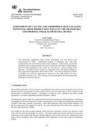
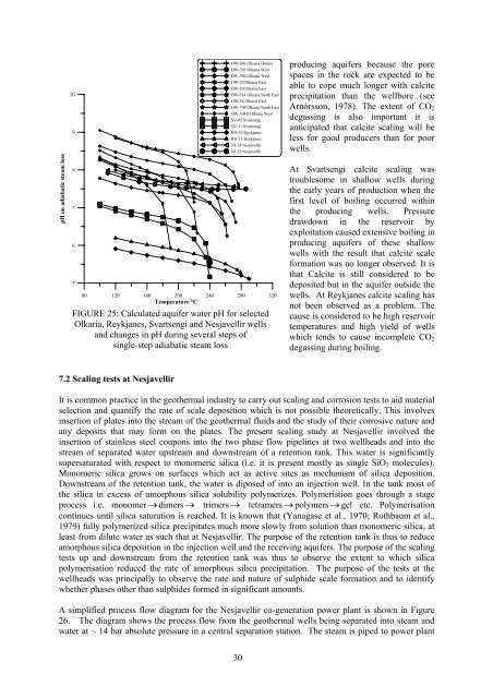
FIGURE 25: Calcul<strong>at</strong>ed aquifer w<strong>at</strong>er pH for selected<br />
Olkaria, Reykjanes, Svartsengi <strong>and</strong> Nesjavellir <strong>wells</strong><br />
<strong>and</strong> changes <strong>in</strong> pH dur<strong>in</strong>g several steps of<br />
s<strong>in</strong>gle-step adiab<strong>at</strong>ic steam loss<br />
produc<strong>in</strong>g aquifers because the pore<br />
spaces <strong>in</strong> the rock are expected to be<br />
able to cope much longer with calcite<br />
precipit<strong>at</strong>ion than the wellbore (see<br />
Arnórsson, 1978). The extent of CO 2<br />
degass<strong>in</strong>g is also important it is<br />
anticip<strong>at</strong>ed th<strong>at</strong> calcite <strong>scal<strong>in</strong>g</strong> will be<br />
less for good producers than for poor<br />
<strong>wells</strong>.<br />
At Svartsengi calcite <strong>scal<strong>in</strong>g</strong> was<br />
troublesome <strong>in</strong> shallow <strong>wells</strong> dur<strong>in</strong>g<br />
the early years of production when the<br />
first level of boil<strong>in</strong>g occurred with<strong>in</strong><br />
the produc<strong>in</strong>g <strong>wells</strong>. Pressure<br />
drawdown <strong>in</strong> the reservoir by<br />
exploit<strong>at</strong>ion caused extensive boil<strong>in</strong>g <strong>in</strong><br />
produc<strong>in</strong>g aquifers of these shallow<br />
<strong>wells</strong> with the result th<strong>at</strong> calcite scale<br />
form<strong>at</strong>ion was no longer observed. It is<br />
th<strong>at</strong> Calcite is still considered to be<br />
deposited but <strong>in</strong> the aquifer outside the<br />
<strong>wells</strong>. At Reykjanes calcite <strong>scal<strong>in</strong>g</strong> has<br />
not been observed as a problem. The<br />
cause is considered to be high reservoir<br />
temper<strong>at</strong>ures <strong>and</strong> high yield of <strong>wells</strong><br />
which tends to cause <strong>in</strong>complete CO 2<br />
degass<strong>in</strong>g dur<strong>in</strong>g boil<strong>in</strong>g.<br />
7.2 Scal<strong>in</strong>g tests <strong>at</strong> Nesjavellir<br />
It is common practice <strong>in</strong> the geothermal <strong>in</strong>dustry to carry out <strong>scal<strong>in</strong>g</strong> <strong>and</strong> corrosion tests to aid m<strong>at</strong>erial<br />
selection <strong>and</strong> quantify the r<strong>at</strong>e of scale deposition which is not possible theoretically. This <strong>in</strong>volves<br />
<strong>in</strong>sertion of pl<strong>at</strong>es <strong>in</strong>to the stream of the geothermal fluids <strong>and</strong> the study of their <strong>corrosive</strong> n<strong>at</strong>ure <strong>and</strong><br />
any deposits th<strong>at</strong> may form on the pl<strong>at</strong>es. The present <strong>scal<strong>in</strong>g</strong> study <strong>at</strong> Nesjavellir <strong>in</strong>volved the<br />
<strong>in</strong>sertion of sta<strong>in</strong>less steel coupons <strong>in</strong>to the two phase flow pipel<strong>in</strong>es <strong>at</strong> two wellheads <strong>and</strong> <strong>in</strong>to the<br />
stream of separ<strong>at</strong>ed w<strong>at</strong>er upstream <strong>and</strong> downstream of a retention tank. This w<strong>at</strong>er is significantly<br />
supers<strong>at</strong>ur<strong>at</strong>ed with respect to monomeric silica (i.e. it is present mostly as s<strong>in</strong>gle SiO 2 molecules).<br />
Monomeric silica grows on surfaces which act as active sites as mechanism of silica deposition.<br />
Downstream of the retention tank, the w<strong>at</strong>er is diposed of <strong>in</strong>to an <strong>in</strong>jection well. In the tank most of<br />
the silica <strong>in</strong> excess of amorphous silica solubility polymerizes. Polymeristion goes through a stage<br />
process i.e. monomer → dimers → trimers → tetramers → polymers → gel etc. Polymeris<strong>at</strong>ion<br />
cont<strong>in</strong>ues until silica s<strong>at</strong>ur<strong>at</strong>ion is reached. It is known th<strong>at</strong> (Yanagase et al., 1970; Rothbaum et al.,<br />
1979) fully polymerized silica precipit<strong>at</strong>es much more slowly from solution than monomeric silica, <strong>at</strong><br />
least from dilute w<strong>at</strong>er as such th<strong>at</strong> <strong>at</strong> Nesjavellir. The purpose of the retention tank is thus to reduce<br />
amorphous silica deposition <strong>in</strong> the <strong>in</strong>jection well <strong>and</strong> the receiv<strong>in</strong>g aquifers. The purpose of the <strong>scal<strong>in</strong>g</strong><br />
tests up <strong>and</strong> downstream from the retention tank was thus to observe the extent to which silica<br />
polymeris<strong>at</strong>ion reduced the r<strong>at</strong>e of amorphous silica precipit<strong>at</strong>ion. The purpose of the tests <strong>at</strong> the<br />
wellheads was pr<strong>in</strong>cipally to observe the r<strong>at</strong>e <strong>and</strong> n<strong>at</strong>ure of sulphide scale form<strong>at</strong>ion <strong>and</strong> to identify<br />
whether phases other than sulphides formed <strong>in</strong> significant amounts.<br />
A simplified process flow diagram for the Nesjavellir co-gener<strong>at</strong>ion power plant is shown <strong>in</strong> Figure<br />
26. The diagram shows the process flow from the geothermal <strong>wells</strong> be<strong>in</strong>g separ<strong>at</strong>ed <strong>in</strong>to steam <strong>and</strong><br />
w<strong>at</strong>er <strong>at</strong> ~ 14 bar absolute pressure <strong>in</strong> a central separ<strong>at</strong>ion st<strong>at</strong>ion. The steam is piped to power plant<br />
30