corrosive species and scaling in wells at olkaria ... - Orkustofnun
corrosive species and scaling in wells at olkaria ... - Orkustofnun
corrosive species and scaling in wells at olkaria ... - Orkustofnun

You also want an ePaper? Increase the reach of your titles
YUMPU automatically turns print PDFs into web optimized ePapers that Google loves.
GEOTHERMAL TRAINING PROGRAMME Reports 2006<br />
<strong>Orkustofnun</strong>, Grensásvegur 9, Number 2<br />
IS-108 Reykjavík, Icel<strong>and</strong><br />
CORROSIVE SPECIES AND SCALING IN WELLS<br />
AT OLKARIA, KENYA AND REYKJANES, SVARTSENGI<br />
AND NESJAVELLIR, ICELAND<br />
MSc thesis<br />
Department of Geology <strong>and</strong> Geography, Faculty of Science<br />
University of Icel<strong>and</strong><br />
by<br />
Kizito M. Opondo<br />
Kenya Electricity Gener<strong>at</strong><strong>in</strong>g Co., Ltd. - KenGen<br />
Olkaria Geothermal Project<br />
P.O. Box 785<br />
Naivasha<br />
KENYA<br />
United N<strong>at</strong>ions University<br />
Geothermal Tra<strong>in</strong><strong>in</strong>g Programme<br />
Reykjavík, Icel<strong>and</strong><br />
Published <strong>in</strong> March 2007<br />
ISBN 978-9979-68-210-3
This MSc thesis has also been published <strong>in</strong> August 2006 by the<br />
Department of Geology <strong>and</strong> Geography,<br />
University of Icel<strong>and</strong><br />
ii
INTRODUCTION<br />
The Geothermal Tra<strong>in</strong><strong>in</strong>g Programme of the United N<strong>at</strong>ions University (UNU) has<br />
oper<strong>at</strong>ed <strong>in</strong> Icel<strong>and</strong> s<strong>in</strong>ce 1979 with six month annual courses for professionals from<br />
develop<strong>in</strong>g countries. The aim is to assist develop<strong>in</strong>g countries with significant<br />
geothermal potential to build up groups of specialists th<strong>at</strong> cover most aspects of<br />
geothermal explor<strong>at</strong>ion <strong>and</strong> development. Dur<strong>in</strong>g 1979-2006, 359 scientists <strong>and</strong><br />
eng<strong>in</strong>eers from 40 countries have completed the six month courses. They have come<br />
from Asia (44%), Africa (26%), Central America (14%), <strong>and</strong> Central <strong>and</strong> Eastern Europe<br />
(16%). There is a steady flow of requests from all over the world for the six month<br />
tra<strong>in</strong><strong>in</strong>g <strong>and</strong> we can only meet a portion of the requests. Most of the tra<strong>in</strong>ees are awarded<br />
UNU Fellowships f<strong>in</strong>anced by the UNU <strong>and</strong> the Government of Icel<strong>and</strong>.<br />
C<strong>and</strong>id<strong>at</strong>es for the six month specialized tra<strong>in</strong><strong>in</strong>g must have <strong>at</strong> least a BSc degree <strong>and</strong> a<br />
m<strong>in</strong>imum of one year practical experience <strong>in</strong> geothermal work <strong>in</strong> their home countries<br />
prior to the tra<strong>in</strong><strong>in</strong>g. Many of our tra<strong>in</strong>ees have already completed their MSc or PhD<br />
degrees when they come to Icel<strong>and</strong>, but several excellent students who have only BSc<br />
degrees have made requests to come aga<strong>in</strong> to Icel<strong>and</strong> for a higher academic degree. In<br />
1999, it was decided to start admitt<strong>in</strong>g UNU Fellows to cont<strong>in</strong>ue their studies <strong>and</strong> study<br />
for MSc degrees <strong>in</strong> geothermal science or eng<strong>in</strong>eer<strong>in</strong>g <strong>in</strong> co-oper<strong>at</strong>ion with the University<br />
of Icel<strong>and</strong>. An agreement to this effect was signed with the University of Icel<strong>and</strong>. The six<br />
month studies <strong>at</strong> the UNU Geothermal Tra<strong>in</strong><strong>in</strong>g Programme form a part of the gradu<strong>at</strong>e<br />
programme.<br />
It is a pleasure to <strong>in</strong>troduce the n<strong>in</strong>th UNU Fellow to complete the MSc studies <strong>at</strong> the<br />
University of Icel<strong>and</strong> under the co-oper<strong>at</strong>ion agreement. Mr. Kizito M. Opondo, BSc <strong>in</strong><br />
Chemistry, of the Kenya Electricity Gener<strong>at</strong><strong>in</strong>g Co. Ltd KenGen, completed the six<br />
month specialized tra<strong>in</strong><strong>in</strong>g <strong>at</strong> the UNU Geothermal Tra<strong>in</strong><strong>in</strong>g Programme <strong>in</strong> October 2002.<br />
His research report was entitled “Corrosion tests <strong>in</strong> cool<strong>in</strong>g circuit w<strong>at</strong>er <strong>at</strong> Olkaria I plant<br />
<strong>and</strong> scale predictions for Olkaria <strong>and</strong> Reykjanes fluids”. After two years of geothermal<br />
research work <strong>in</strong> Kenya, he came back to Icel<strong>and</strong> for MSc studies <strong>at</strong> the Faculty of<br />
Science of the University of Icel<strong>and</strong> <strong>in</strong> February 2005. In August 2006, he defended his<br />
MSc thesis presented here, entitled “Corrosive <strong>species</strong> <strong>and</strong> <strong>scal<strong>in</strong>g</strong> <strong>in</strong> <strong>wells</strong> <strong>at</strong> Olkaria,<br />
Kenya, <strong>and</strong> Reykjanes, Svartsengi <strong>and</strong> Nesjavellir, Icel<strong>and</strong>”. His studies <strong>in</strong> Icel<strong>and</strong> were<br />
f<strong>in</strong>anced by a fellowship from the Government of Icel<strong>and</strong> through the UNU Geothermal<br />
Tra<strong>in</strong><strong>in</strong>g Programme. We congr<strong>at</strong>ul<strong>at</strong>e him on his achievements <strong>and</strong> wish him all the best<br />
for the future. We thank the Faculty of Science of the University of Icel<strong>and</strong> for the cooper<strong>at</strong>ion,<br />
<strong>and</strong> his supervisors for the dedic<strong>at</strong>ion.<br />
F<strong>in</strong>ally, I would like to mention th<strong>at</strong> Kizito’s MSc thesis with the photos <strong>in</strong> colour is<br />
available for download<strong>in</strong>g on our website <strong>at</strong> page www.os.is/unugtp/yearbook/2006.<br />
With warmest wishes from Icel<strong>and</strong>,<br />
Ingvar B. Fridleifsson, director<br />
United N<strong>at</strong>ions University<br />
Geothermal Tra<strong>in</strong><strong>in</strong>g Programme<br />
iii
DEDICATION<br />
I would like to dedic<strong>at</strong>e this work to my parents, my l<strong>at</strong>e f<strong>at</strong>her Peter Opondo Mut<strong>and</strong>a <strong>and</strong> my l<strong>at</strong>e<br />
mother Christ<strong>in</strong>e Nasike Opondo for show<strong>in</strong>g me the way of school <strong>at</strong> a very early stage <strong>in</strong> life <strong>and</strong> to<br />
all those who may not be mentioned here but who made immense contributions <strong>in</strong> my early school<strong>in</strong>g<br />
life.<br />
ACKNOWLEDGEMENTS<br />
I would like to express my gr<strong>at</strong>itude to Dr. Ingvar Birgir Fridleifsson, the Director, United N<strong>at</strong>ions<br />
University (UNU) Geothermal Tra<strong>in</strong><strong>in</strong>g Programme (GTP) for hav<strong>in</strong>g offered me the opportunity to<br />
<strong>at</strong>tend the MSc. Programme under the University of Icel<strong>and</strong>-UNU GTP co-oper<strong>at</strong>ion programme <strong>and</strong><br />
for his encouragement <strong>and</strong> guidance throughout the entire course, but also to Mr. Lúdvík S.Georgsson<br />
<strong>and</strong> Gudrún Bjarnadóttir of UNU (GTP) for be<strong>in</strong>g of gre<strong>at</strong> help whenever I needed it.<br />
I extend my gr<strong>at</strong>itude <strong>and</strong> <strong>in</strong>debtedness to my supervisors Prof. Stefán Arnόrsson <strong>and</strong> Mr. Sverrir<br />
Thórhallsson for hav<strong>in</strong>g been there the whole way <strong>and</strong> provid<strong>in</strong>g a very supportive environment for<br />
my research along with much guidance. The lecturers <strong>at</strong> the University of Icel<strong>and</strong> provided a gre<strong>at</strong><br />
learn<strong>in</strong>g experience <strong>and</strong> my s<strong>in</strong>cere gr<strong>at</strong>itude to them. My s<strong>in</strong>cere appreci<strong>at</strong>ion to Gestur Gíslason <strong>and</strong><br />
Grétar Ívarsson of Orkuveita Reykjavíkur for assistance with all the field work <strong>at</strong> Nesjavellir, to Dr.<br />
Sigurdur Jakobsson for analysis <strong>and</strong> <strong>in</strong>terpret<strong>at</strong>ion of <strong>in</strong>frared spectroscopy, to Ingvi Gunnarsson <strong>and</strong><br />
Jόn M<strong>at</strong>thίasson for analysis with the Inductively Coupled Plasma (ICP) <strong>and</strong> the Scann<strong>in</strong>g Electron<br />
Microscope (SEM) <strong>and</strong> Sigurdur Jόnsson for the X-Ray Diffraction spectra (XRD), to the staff of<br />
Icel<strong>and</strong> Geosurvey (ISOR) <strong>and</strong> <strong>Orkustofnun</strong> (OS) with whom <strong>in</strong>teraction was of gre<strong>at</strong> help. To Niels<br />
Giroud for provid<strong>in</strong>g chemical d<strong>at</strong>a for Nesjavellir well fluids <strong>and</strong> Halldόr Ármannsson for chemical<br />
d<strong>at</strong>a for Reykjanes <strong>and</strong> Svartsengi well fluids. Special thanks are extended to my fellow students with<br />
whom <strong>in</strong>teraction was very encourag<strong>in</strong>g throughout my study.<br />
I would like to thank <strong>in</strong>stitutions <strong>and</strong> organis<strong>at</strong>ions th<strong>at</strong> funded <strong>and</strong> supported my studies; The<br />
Government of Icel<strong>and</strong> through the UNU Geothermal Tra<strong>in</strong><strong>in</strong>g Programme (UNU-GTP) <strong>and</strong><br />
Orkuveita Reykjavíkur (Icel<strong>and</strong>). To my employer, the Kenya Electricity Gener<strong>at</strong><strong>in</strong>g Company Ltd<br />
(KenGen) for grant<strong>in</strong>g me study leave to carry out this study.<br />
My deepest thanks to my wife, Eunice who played dad <strong>and</strong> mum dur<strong>in</strong>g my long period of absence,<br />
my daughters Christ<strong>in</strong>e Nasike, Esther Narotso, Lynn Nabwire all who had to bare with my long<br />
absence. You all were of gre<strong>at</strong> encouragement whenever I phoned <strong>and</strong> talked to you. To almighty<br />
God for keep<strong>in</strong>g me <strong>in</strong> good health dur<strong>in</strong>g my entire stay.<br />
iv
ABSTRACT<br />
The Olkaria geothermal system <strong>in</strong> Kenya is loc<strong>at</strong>ed with<strong>in</strong> the Okaria volcanic complex <strong>in</strong> the central<br />
sector of the Kenya Rift Valley. Reykjanes, Svarstengi <strong>and</strong> Nesjavellir geothermal fields are loc<strong>at</strong>ed<br />
<strong>in</strong> southwest Icel<strong>and</strong> <strong>and</strong> fall on a cont<strong>in</strong>uous earthquake epicentric l<strong>in</strong>e extend<strong>in</strong>g through the<br />
Reykjanes Penn<strong>in</strong>sula th<strong>at</strong> stretches northeast to Langjökull. These four geothermal fields are all<br />
high-temper<strong>at</strong>ure. Measured temper<strong>at</strong>ures <strong>in</strong> Olkaria are as high as 350°C, Reykjanes 320°C,<br />
Svartsengi 240°C <strong>and</strong> Nesjavellir > 380°C. The reservoir w<strong>at</strong>ers <strong>in</strong> the four fields vary. The w<strong>at</strong>er type<br />
<strong>at</strong> Olkaria is ma<strong>in</strong>ly dilute near neutral pH sodium -chloride <strong>and</strong> sodium-bicarbon<strong>at</strong>e w<strong>at</strong>ers with<br />
chloride rang<strong>in</strong>g between 50 <strong>and</strong> 4000 ppm <strong>at</strong> <strong>at</strong>mospheric pressure. At Reykjanes <strong>and</strong> Svartsengi<br />
these are sal<strong>in</strong>e sodium-chloride w<strong>at</strong>ers with chloride be<strong>in</strong>g 20,000 <strong>and</strong> 13,000 ppm, respectively,<br />
while <strong>at</strong> Nesjavellir they are very dilute sodium chloride w<strong>at</strong>ers with chloride of ~ 150 ppm.<br />
Gas concentr<strong>at</strong>ions <strong>in</strong> the fluids of all the four fields are low, except for fluids of the Olkaria West<br />
sector <strong>in</strong> Olkaria. Speci<strong>at</strong>ion calcul<strong>at</strong>ions <strong>in</strong>dic<strong>at</strong>e th<strong>at</strong> <strong>in</strong> Olkaria CO 2 partial pressures range between<br />
0.5 bar <strong>and</strong> 5 bar except for fluids <strong>in</strong> the Olkaria West sector with > 90 bars a. At Reykjanes,<br />
Svartsengi <strong>and</strong> Nesjavellir the CO 2 partial pressures fall between 0.0867 to 1.66 bars a. The high CO 2<br />
partial pressures cause CO 2 rich w<strong>at</strong>ers to develop when CO 2 <strong>in</strong> steam encounters shallower ground<br />
w<strong>at</strong>ers. This becomes <strong>corrosive</strong> <strong>in</strong> the process as the pH of the w<strong>at</strong>er is lowered. At Reykjanes <strong>and</strong><br />
Svartsengi, well fluids are low <strong>in</strong> pH but this is little <strong>in</strong>fluenced by the partial pressures of CO 2 . The<br />
pH of condens<strong>at</strong>es th<strong>at</strong> form due to dissolution of CO 2 <strong>at</strong> separ<strong>at</strong>ion pressures range between 4.55 <strong>and</strong><br />
5.51 for Olkaria <strong>wells</strong> while <strong>at</strong> Reykjanes, Svartsengi <strong>and</strong> Nesjavellir these are between 5.20 <strong>and</strong> 5.55.<br />
Thermodynamic calcul<strong>at</strong>ions of HCl concentr<strong>at</strong>ions us<strong>in</strong>g pH, chloride concentr<strong>at</strong>ions <strong>and</strong> aquifer<br />
temper<strong>at</strong>ure <strong>in</strong>dic<strong>at</strong>e high concentr<strong>at</strong>ions of HCl <strong>in</strong> the aquifer w<strong>at</strong>er of Reykjanes <strong>and</strong> Svartsengi<br />
(0.81 <strong>and</strong> 0.083 ppm) <strong>and</strong> low HCl concentr<strong>at</strong>ions <strong>in</strong> the Olkaria <strong>and</strong> Nesjavellir well fluids. In steam<br />
high HCl concentr<strong>at</strong>ions are derived for Reykjanes well fluids due to high wellhead pressures. Low<br />
pH <strong>and</strong> high chloride concentr<strong>at</strong>ion coupled with high temper<strong>at</strong>ures contribute to high HCl<br />
concentr<strong>at</strong>ions <strong>in</strong> fluid <strong>in</strong> the Reykjanes <strong>and</strong> Svartsengi fluids. In dry steam conveyed <strong>in</strong> steam<br />
g<strong>at</strong>her<strong>in</strong>g systems HCl becomes <strong>corrosive</strong> as steam condenses due to form<strong>at</strong>ion of H + <strong>and</strong> Cl - ions.<br />
Studies of scales formed dur<strong>in</strong>g tests <strong>at</strong> Nesjavellir us<strong>in</strong>g the b<strong>in</strong>ocular microscope, FTIR, XRD, SEM,<br />
ICP <strong>and</strong> UV <strong>in</strong>dic<strong>at</strong>e th<strong>at</strong> scales formed <strong>at</strong> the wellheads of <strong>wells</strong> NJ-14 <strong>and</strong> NJ-22 consisted ma<strong>in</strong>ly<br />
of sulphides <strong>at</strong> well NJ-14 <strong>and</strong> mixed sulphides <strong>and</strong> oxides <strong>at</strong> well NJ-22. In separ<strong>at</strong>ed w<strong>at</strong>er after the<br />
he<strong>at</strong> exchangers, entry to retention tank <strong>and</strong> <strong>at</strong> <strong>in</strong>jection well the scales consisted ma<strong>in</strong>ly of amorphous<br />
silica with some <strong>in</strong>dic<strong>at</strong>ion of clays. Crystall<strong>in</strong>e phases were not prom<strong>in</strong>ent <strong>in</strong> the scales but traces of<br />
chalcopyrite were identified <strong>in</strong> scales formed <strong>at</strong> the wellhead of well NJ-14 <strong>and</strong> <strong>at</strong> the entry to the<br />
retention tank. Traces of clays formed <strong>in</strong> scales <strong>at</strong> the wellhead of well NJ-22. The highest amount of<br />
scale deposited <strong>at</strong> the entry to the retention tank, with a deposition r<strong>at</strong>e of ~0.261mm/yr. At the<br />
<strong>in</strong>jection well the r<strong>at</strong>e was lower ~0.0168 mm/yr.<br />
Olkaria well OW-34 has an enthalpy close to th<strong>at</strong> of dry steam of 2672 kJ/kg <strong>and</strong> anomalous<br />
chemistry. Chloride concentr<strong>at</strong>ion <strong>in</strong> the separ<strong>at</strong>ed w<strong>at</strong>er is ~ 4000ppm <strong>at</strong> <strong>at</strong>mospheric pressure. The<br />
high solute content <strong>in</strong> well OW-34 fluids is <strong>in</strong>fluenced by evapor<strong>at</strong>ive effects due to the high discharge<br />
enthalpy. Scales formed <strong>in</strong> the wellhead equipment <strong>and</strong> studied by the same method above <strong>in</strong>dic<strong>at</strong>ed<br />
they were prom<strong>in</strong>ently amorphous silica scales. Crystall<strong>in</strong>e phases were absent from the scales.<br />
v
TABLE OF CONTENTS<br />
Page<br />
1. INTRODUCTION ................................................................................................................... 1<br />
1.1 Corrosion <strong>in</strong> geothermal environments.......................................................................... 1<br />
1.2 Scale form<strong>at</strong>ion.............................................................................................................. 2<br />
1.2.1 Silica................................................................................................................ 2<br />
1.2.2 Calcite.............................................................................................................. 4<br />
1.2.3 Other scales ..................................................................................................... 4<br />
1.2.4 Objectives of study .......................................................................................... 5<br />
2. GEOLOGICAL FEATURES OF THE STUDY AREA.......................................................... 6<br />
2.1 The Gre<strong>at</strong>er Olkaria geothermal system ........................................................................ 6<br />
2.2 The Reykjanes <strong>and</strong> Svartsengi geothermal fields .......................................................... 7<br />
2.3 Nesjavellir geothermal field........................................................................................... 9<br />
3. SAMPLING AND ANALYSIS............................................................................................. 11<br />
3.1 Sample collection......................................................................................................... 11<br />
3.2 Analysis of w<strong>at</strong>er <strong>and</strong> steam samples .......................................................................... 12<br />
4. FLUID COMPOSITIONS ..................................................................................................... 13<br />
5. CALCULATION OF AQUIFER FLUID COMPOSITION.................................................. 15<br />
5.1 Discharge enthalpy of <strong>wells</strong>......................................................................................... 15<br />
5.2 Calcul<strong>at</strong>ion of gas concentr<strong>at</strong>ions <strong>in</strong> steam <strong>at</strong> <strong>at</strong>mospheric pressure ........................... 17<br />
5.3 Calcul<strong>at</strong>ion of aquifer w<strong>at</strong>er compositions <strong>and</strong> speci<strong>at</strong>ion distribution....................... 18<br />
6. POTENTIAL CORROSION BY CO 2 AND HCl .................................................................. 20<br />
6.1 Carbon dioxide............................................................................................................. 20<br />
6.2 Hydrogen chloride ....................................................................................................... 22<br />
7. SCALING IN WELLS AND SURFACE INSTALLATIONS .............................................. 28<br />
7.1 Theoretical aspects of calcite scale form<strong>at</strong>ion ............................................................. 28<br />
7.2 Scal<strong>in</strong>g tests <strong>at</strong> Nesjavellir........................................................................................... 30<br />
7.2.1 Test coupons.................................................................................................. 31<br />
7.2.2 Test procedures <strong>and</strong> selection of test sites for the study................................ 32<br />
7.3 Analysis of scales......................................................................................................... 33<br />
7.3.1 B<strong>in</strong>ocular microscope descriptions................................................................ 34<br />
7.3.2 Fourier transform <strong>in</strong>frared measurement....................................................... 35<br />
7.3.3 X-ray diffraction measurements .................................................................... 35<br />
7.3.4 Chemical analysis by Scann<strong>in</strong>g Electron Microscopy –<br />
Electron Dispersive Spectroscopy (SEM-EDS) ......................................... 37<br />
7.3.5 Chemical analysis of scales by the Inductively Coupled Plasma –<br />
Atomic Emission Spectra (ICP-AES)......................................................... 38<br />
7.3.6 Analysis of scales <strong>in</strong> the UV spectroscopy.................................................... 38<br />
7.3.7 Quantity of scales .......................................................................................... 38<br />
8. EVALUATION OF SCALES DEPOSITED AT OLKARIA WELL OW-34, KENYA....... 41<br />
8.1 Output characteristics of well OW-34 ......................................................................... 41<br />
8.2 W<strong>at</strong>er composition of well OW-34.............................................................................. 42<br />
8.3 Chloride concentr<strong>at</strong>ion as a function of vapour pressure<br />
<strong>at</strong> selected discharge enthalpies ................................................................................ 42<br />
8.4 Scales deposited <strong>at</strong> well OW-34 .................................................................................. 43<br />
8.5 Analysis of scales from well OW-34........................................................................... 44<br />
vi
Page<br />
9. CONCLUSIONS ................................................................................................................... 47<br />
REFERENCES ................................................................................................................... 49<br />
APPENDIX A: Tables with analyses, calcul<strong>at</strong>ion etc..................................................................... 57<br />
APPENDIX B: Methods for prepar<strong>in</strong>g coupons <strong>and</strong> study<strong>in</strong>g scales ............................................. 65<br />
APPENDIX C: Analyses of scales <strong>and</strong> scales spectra .................................................................... 66<br />
LIST OF FIGURES<br />
1. Kenya Rift system <strong>and</strong> the major geothermal prospect <strong>and</strong> Olkaria geothermal field............. 6<br />
2. Loc<strong>at</strong>ion of the geothermal fields <strong>in</strong> the Gre<strong>at</strong>er Olkaria Geothermal Area............................ 7<br />
3. Simplified geological map with high-temper<strong>at</strong>ure geothermal fields <strong>in</strong> Icel<strong>and</strong> ..................... 8<br />
4. Loc<strong>at</strong>ion of <strong>wells</strong> <strong>in</strong> Reykjanes geothermal field..................................................................... 8<br />
5. Well loc<strong>at</strong>ions <strong>in</strong> the Svartsengi geothermal field ................................................................... 9<br />
6. Resistivity map del<strong>in</strong>e<strong>at</strong><strong>in</strong>g the l<strong>at</strong>eral extent of the Hengill geothermal area......................... 9<br />
7. Loc<strong>at</strong>ion of <strong>wells</strong> <strong>in</strong> the Nesjavellir geothermal field ............................................................ 10<br />
8. Steam collection us<strong>in</strong>g a Webre separ<strong>at</strong>or <strong>and</strong> w<strong>at</strong>er sample collection from a weirbox ...... 11<br />
9. Steam collection from a steam separ<strong>at</strong>or <strong>and</strong> w<strong>at</strong>er sample collection from a weirbox ........ 11<br />
10. Cl-SO 4 -HCO 3 ternary plot for fluids from the Olkaria, Reykjanes <strong>and</strong> Svartsengi fields ..... 13<br />
11. Rel<strong>at</strong>ionship between tqtz vs. tNaK equilibrium temper<strong>at</strong>ures.............................................. 16<br />
12. Difference between tNa/K <strong>and</strong> tqtz geothermometer temper<strong>at</strong>ures vs. enthalpy................... 16<br />
13. Aquifer temper<strong>at</strong>ures vs. CO 2 partial pressures <strong>in</strong> the aquifer fluids..................................... 20<br />
14. Aquifer pH vs CO 2 partial pressures <strong>in</strong> the aquifer for selected <strong>wells</strong> <strong>in</strong> the study areas ...... 21<br />
15. CO 2 <strong>in</strong> the separ<strong>at</strong>ed w<strong>at</strong>er of selected <strong>wells</strong> with s<strong>in</strong>gle-step adiab<strong>at</strong>ic steam loss .............. 22<br />
16. CO 2 <strong>in</strong> the separ<strong>at</strong>ed w<strong>at</strong>er of selected <strong>wells</strong> with s<strong>in</strong>gle-step adiab<strong>at</strong>ic steam loss .............. 22<br />
17. Condens<strong>at</strong>e pH <strong>at</strong> separ<strong>at</strong>ion temper<strong>at</strong>ures of selected <strong>wells</strong> <strong>in</strong> the study area ..................... 22<br />
18. Aquifer w<strong>at</strong>er HCl concentr<strong>at</strong>ions vs. aquifer w<strong>at</strong>er chloride concentr<strong>at</strong>ions <strong>in</strong> <strong>wells</strong>.......... 24<br />
19. Aquifer w<strong>at</strong>er HCl concentr<strong>at</strong>ions vs. aquifer w<strong>at</strong>er pH of selected <strong>wells</strong> <strong>in</strong> the study area . 24<br />
20. Aquifer w<strong>at</strong>er HCl concentr<strong>at</strong>ions vs. aquifer temper<strong>at</strong>ure of selected <strong>wells</strong> ........................ 25<br />
21. HCl <strong>in</strong> vapour formed by s<strong>in</strong>gle-step adiab<strong>at</strong>ic boil<strong>in</strong>g of selected <strong>wells</strong> <strong>in</strong> the study areas. 25<br />
22. HCl <strong>in</strong> vapour with changes <strong>in</strong> pH upon s<strong>in</strong>gle-step adiab<strong>at</strong>ic boil<strong>in</strong>g of selected <strong>wells</strong> ...... 26<br />
23. Aquifer pH vs calcite s<strong>at</strong>ur<strong>at</strong>ion for Olkaria, Reykjanes, Svartsengi <strong>and</strong> Nesjavellir ........... 28<br />
24. Changes <strong>in</strong> calcite produced by s<strong>in</strong>gle-step adiab<strong>at</strong>ic steam loss for selected well fluid....... 29<br />
25. Calcul<strong>at</strong>ed aquifer w<strong>at</strong>er pH for selected <strong>wells</strong> <strong>and</strong> changes <strong>in</strong> pH<br />
dur<strong>in</strong>g s<strong>in</strong>gle-step adiab<strong>at</strong>ic steam loss........................................................................ 30<br />
26. Simplified process diagram of the Nesjavellir co-gener<strong>at</strong>ion power plant. ........................... 31<br />
27. Prepared test coupons with impr<strong>in</strong>ted identific<strong>at</strong>ion number codes ...................................... 31<br />
28. Retractable coupon holders ................................................................................................... 32<br />
29. Coupons <strong>at</strong> the well head of well NJ-14 ................................................................................ 33<br />
30. Coupons <strong>at</strong> entry to the retention tank ................................................................................... 33<br />
31. Coupons <strong>at</strong> the re-<strong>in</strong>jection well ............................................................................................ 33<br />
32. Test coupons after 13 weeks test period ................................................................................ 34<br />
33. Deposition of scales on test coupons <strong>at</strong> different loc<strong>at</strong>ions ................................................... 34<br />
34. IR spectra of scales deposited on coupons <strong>at</strong> various loc<strong>at</strong>ions............................................. 36<br />
35. XRD spectra of scales formed <strong>at</strong> wellheads of Nesjavellir <strong>wells</strong> .......................................... 37<br />
36. Scann<strong>in</strong>g Electron Micrograph show<strong>in</strong>g crystals of sulphides from scale on test coupons... 37<br />
37. Weight ga<strong>in</strong> of scale <strong>at</strong> various test sites for 13 weeks test <strong>and</strong> 29 weeks test ...................... 39<br />
38. Scale thickness <strong>at</strong> the various test sites for 13 weeks test <strong>and</strong> 29 weeks test......................... 40<br />
vii
39. Loc<strong>at</strong>ion of <strong>wells</strong> <strong>in</strong> Olkaria East production field ................................................................ 41<br />
40. Modelled chloride concentr<strong>at</strong>ions <strong>at</strong> selected enthalpies with vary<strong>in</strong>g vapour pressure........ 42<br />
41. Layout of wellhead for well OW-34 show<strong>in</strong>g where scale samples were collected.............. 43<br />
42. Scale deposited on two-phase l<strong>in</strong>e of well OW-34 (scale # 2)............................................... 44<br />
43. Scale sample from <strong>in</strong>side the separ<strong>at</strong>or of well OW-34 (scale # 3) ....................................... 44<br />
44. Scale formed <strong>at</strong> the Tee connection of well OW-34 master valve (scale # 1) ....................... 44<br />
45. Scale deposit on the waste w<strong>at</strong>erl<strong>in</strong>e of well OW-34 (scale # 4)........................................... 44<br />
46. Deposit of scale formed where well OW-34 master valve was leak<strong>in</strong>g (scale #5) ............... 44<br />
47. Infrared spectra of scale samples #1 – 5, collected from well OW-34 .................................. 45<br />
48. XRD analysis of scale samples #1 – 5 from Olkaria well OW-34......................................... 46<br />
Page<br />
viii
1. INTRODUCTION<br />
For many countries geothermal energy is an important resource. Utilis<strong>at</strong>ion, both direct <strong>and</strong> for power<br />
gener<strong>at</strong>ion, is <strong>in</strong>creas<strong>in</strong>g faster than th<strong>at</strong> of any other energy resource. Worldwide <strong>in</strong>stalled capacity of<br />
geothermal power plants has <strong>in</strong>creased by ~ 10 % or more per year over the last two decades (Bert<strong>in</strong>i,<br />
2005). The technology needed to harness geothermal energy has advanced much over the last 20-30<br />
years <strong>and</strong> steps have been taken to reduce the environmental impact of geothermal energy utiliz<strong>at</strong>ion,<br />
particularly by <strong>in</strong>jection of spent fluid <strong>in</strong>to <strong>wells</strong> <strong>and</strong> directional drill<strong>in</strong>g. The ma<strong>in</strong> oper<strong>at</strong>ional<br />
problems encountered when utilis<strong>in</strong>g high-temper<strong>at</strong>ure geothermal reservoirs for power gener<strong>at</strong>ion<br />
<strong>in</strong>volve the form<strong>at</strong>ion of various types of scales <strong>in</strong> production <strong>wells</strong>, surface equipment <strong>and</strong> <strong>in</strong>jection<br />
<strong>wells</strong>. Corrosion is sometimes also a problem, both for high <strong>and</strong> low-temper<strong>at</strong>ure fluid utilis<strong>at</strong>ion.<br />
The most common scales formed are amorphous silica <strong>and</strong> calcite. However, many other types of<br />
scales have been encountered <strong>in</strong>clud<strong>in</strong>g metal-sulphides, silic<strong>at</strong>es of iron <strong>and</strong> alum<strong>in</strong>ium <strong>and</strong><br />
anhydrite. In geothermal fluids various <strong>species</strong> can be <strong>corrosive</strong> <strong>and</strong> these <strong>in</strong>clude chlorides, carbon<br />
dioxide, ammonia, hydrogen ion, dissolved oxygen, bisulph<strong>at</strong>e, which dissoci<strong>at</strong>es <strong>in</strong>to sulph<strong>at</strong>e <strong>and</strong> H +<br />
upon cool<strong>in</strong>g. Chloride ion breaks passive films th<strong>at</strong> are protective on metal surfaces <strong>and</strong> can<br />
concentr<strong>at</strong>e <strong>in</strong> crevices <strong>and</strong> cause pitt<strong>in</strong>g corrosion. Hydrogen chloride <strong>in</strong> steam can produce acid<br />
condens<strong>at</strong>e <strong>and</strong> lead to severe corrosion. Dissolved carbon dioxide gas <strong>in</strong> geothermal w<strong>at</strong>er causes<br />
corrosion of low carbon steels, which is generally localized.<br />
In this study special <strong>at</strong>tention is given to assess<strong>in</strong>g the conditions for the form<strong>at</strong>ion of amorphous silica<br />
<strong>and</strong> calcite scales, <strong>and</strong> the concentr<strong>at</strong>ions of the <strong>corrosive</strong> <strong>species</strong> CO 2 <strong>and</strong> HCl <strong>in</strong> geothermal w<strong>at</strong>er<br />
<strong>and</strong> steam. Special <strong>at</strong>tention is given to <strong>scal<strong>in</strong>g</strong> <strong>in</strong> <strong>wells</strong> <strong>and</strong> wellhead equipment th<strong>at</strong> are <strong>in</strong> contact<br />
with slightly wet steam. The study is based on d<strong>at</strong>a from Olkaria, Kenya <strong>and</strong> Reykjanes, Svartsengi<br />
<strong>and</strong> Nesjavellir, Icel<strong>and</strong>. Further <strong>scal<strong>in</strong>g</strong> tests were carried out <strong>at</strong> Nesjavellir, Icel<strong>and</strong>, both <strong>at</strong><br />
wellheads <strong>and</strong> downstream, where the separ<strong>at</strong>ed w<strong>at</strong>er was overs<strong>at</strong>ur<strong>at</strong>ed with respect to amorphous<br />
silica.<br />
1.1 Corrosion <strong>in</strong> geothermal environments<br />
Corrosive <strong>at</strong>tack <strong>in</strong> high-temper<strong>at</strong>ure geothermal <strong>in</strong>stall<strong>at</strong>ions is found ma<strong>in</strong>ly <strong>in</strong> well cas<strong>in</strong>gs,<br />
condens<strong>at</strong>e <strong>in</strong>jection pipel<strong>in</strong>es made of carbon steel, wellhead equipment <strong>and</strong> turb<strong>in</strong>e blades. In<br />
gener<strong>at</strong>ion of electricity by direct contact condens<strong>in</strong>g turb<strong>in</strong>es where a cool<strong>in</strong>g w<strong>at</strong>er circuit is utilized,<br />
low pH (4-5) of the condens<strong>at</strong>e is caused by the dissolution of CO 2 <strong>and</strong> H 2 S gases present <strong>in</strong> the steam.<br />
In condens<strong>at</strong>e <strong>in</strong>jection pipel<strong>in</strong>es made of carbon steel, Villa et al. (2001) <strong>and</strong> Villa <strong>and</strong> Salonga<br />
(2000) report rapid deterior<strong>at</strong>ion due to low pH of condens<strong>at</strong>es. Oxygen <strong>in</strong>gress exacerb<strong>at</strong>es the<br />
problem. When conductive he<strong>at</strong> losses occur along steam pipel<strong>in</strong>es, steam may condense <strong>and</strong> through<br />
dissolution of CO 2 <strong>and</strong> H 2 S, lower the pH (Tha<strong>in</strong> et al., 1981; Henley et al., 1984). In Olkaria,<br />
Svartsengi <strong>and</strong> Nesjavellir direct contact condens<strong>in</strong>g turb<strong>in</strong>es are utilized <strong>and</strong> low pH condens<strong>at</strong>es<br />
which are <strong>corrosive</strong> develop. Corrosion rel<strong>at</strong>ed to the low pH condens<strong>at</strong>es on disposal is not reported.<br />
In superhe<strong>at</strong>ed steam where HCl is present Allegr<strong>in</strong>i <strong>and</strong> Benvenuti (1970), Meeker <strong>and</strong> Haizlip<br />
(1990) <strong>and</strong> Truesdell (1991) describe severe corrosion <strong>in</strong> well cas<strong>in</strong>gs, steam g<strong>at</strong>her<strong>in</strong>g systems <strong>and</strong><br />
turb<strong>in</strong>e blades, ma<strong>in</strong>ly caused by H + <strong>and</strong> Cl - . Thόrhallsson (2005) reported corrosion <strong>in</strong> steam<br />
pipel<strong>in</strong>es due to HCl transported <strong>in</strong> the steam <strong>in</strong> a dry steam well <strong>at</strong> Svartsengi. In Svartsengi,<br />
Thórólfsson (2005) has reported various corrosion rel<strong>at</strong>ed problems observed dur<strong>in</strong>g ma<strong>in</strong>tenance of<br />
the plant.<br />
Corrosion of cas<strong>in</strong>g <strong>in</strong> high-temper<strong>at</strong>ure geothermal systems can also be rel<strong>at</strong>ed to low pH associ<strong>at</strong>ed<br />
with acid-sulph<strong>at</strong>e w<strong>at</strong>ers. In <strong>and</strong>esitic geothermal systems like those found <strong>in</strong> the Philipp<strong>in</strong>es, e.g. the<br />
Tiwi <strong>and</strong> Bacman fields, Sugiaman et al. (2004) <strong>and</strong> Rosell <strong>and</strong> Ramos (1998) report cas<strong>in</strong>g corrosion<br />
observed due to penetr<strong>at</strong>ion by low pH acid sulph<strong>at</strong>e w<strong>at</strong>er. Similar cas<strong>in</strong>g corrosion was reported <strong>in</strong><br />
Cerro Prieto, Mexico by Dom<strong>in</strong>quiz (1980) <strong>and</strong> Miravalles, Costa Rica by Moya et al. (2005). In<br />
1
other cases, cas<strong>in</strong>g corrosion has been caused by CO 2 rich w<strong>at</strong>ers <strong>in</strong> geothermal fields. These w<strong>at</strong>ers<br />
form when ascend<strong>in</strong>g CO 2 rich steam dissolves <strong>in</strong> near surface shallow w<strong>at</strong>ers. In the Broadl<strong>and</strong>s-<br />
Ohaaki geothermal field, New Zeal<strong>and</strong>, Hedenquist <strong>and</strong> Stewart (1985) reported severe external well<br />
cas<strong>in</strong>g corrosion caused by CO 2 rich steam-he<strong>at</strong>ed w<strong>at</strong>er. Zarouk (2004) reviewed cas<strong>in</strong>g corrosion<br />
occurrences <strong>in</strong> New Zeal<strong>and</strong> geothermal fields. In all cases, these are rel<strong>at</strong>ed to CO 2 rich dilute<br />
geothermal w<strong>at</strong>er. In Olkaria, Omenda (1998) <strong>and</strong> Kar<strong>in</strong>githi (2002) report CO 2 rich fluids but the<br />
extent to which they are <strong>corrosive</strong> is not known.<br />
Modes of corrosion <strong>at</strong>tack <strong>in</strong> geothermal <strong>in</strong>stall<strong>at</strong>ions have been disscussed by Conover et al. (1979),<br />
Boulton <strong>and</strong> White (1983) <strong>and</strong> Corsi (1986). These are uniform (general) corrosion, pitt<strong>in</strong>g corrosion,<br />
crevice corrosion, stress corrosion crack<strong>in</strong>g (SCC), sulphide stress crack<strong>in</strong>g (SSC), <strong>in</strong>tergranular<br />
corrosion, galvanic coupl<strong>in</strong>g, corrosion f<strong>at</strong>igue, microbiological by <strong>in</strong>duced corrosion, erosion<br />
corrosion <strong>and</strong> cavit<strong>at</strong>ion.<br />
1.2 Scale form<strong>at</strong>ion<br />
The ma<strong>in</strong> drawbacks <strong>in</strong> the utiliz<strong>at</strong>ion of geothermal resources arise from the precipit<strong>at</strong>ion of solid<br />
scales from the geothermal fluid. In many cases the scales cause restriction <strong>in</strong> flow, e.g. <strong>in</strong> the<br />
boreholes, two phase pipel<strong>in</strong>es, the separ<strong>at</strong>ors <strong>and</strong> waste w<strong>at</strong>er l<strong>in</strong>es <strong>and</strong> steam pipel<strong>in</strong>es. Their<br />
form<strong>at</strong>ion often impedes the clos<strong>in</strong>g <strong>and</strong> open<strong>in</strong>g of valves lead<strong>in</strong>g to leaks. Deposition on turb<strong>in</strong>e<br />
blades is common which results <strong>in</strong> the turb<strong>in</strong>e chest pressures <strong>in</strong>creas<strong>in</strong>g. Three ma<strong>in</strong> areas of scale<br />
deposition can be dist<strong>in</strong>guished (Corsi, 1986). These are: deposition from a s<strong>in</strong>gle phase fluid<br />
(<strong>in</strong>jection pipel<strong>in</strong>es), deposition from flash<strong>in</strong>g fluid (<strong>wells</strong>, separ<strong>at</strong>ors, two phase-pipel<strong>in</strong>es) <strong>and</strong><br />
deposition by steam carryover (separ<strong>at</strong>ors, steam l<strong>in</strong>es <strong>and</strong> turb<strong>in</strong>es).<br />
A gre<strong>at</strong> deal of work has been carried out on the n<strong>at</strong>ure of scales formed from geothermal fluids<br />
(Thόrhallsson et al., 1975; Arnόrsson, 1981; Gallup, 1989; Gallup, 1998; Simmons <strong>and</strong> Christenson<br />
1993; Simmons <strong>and</strong> Christenson, 1994). Amorphous silica <strong>and</strong> calcium carbon<strong>at</strong>e scales are the most<br />
extensively studied but metal sulphides <strong>and</strong> silic<strong>at</strong>es to a lesser extent, although they are presently<br />
receiv<strong>in</strong>g more <strong>at</strong>tention (Simmons <strong>and</strong> Christenson 1993; Simmons <strong>and</strong> Christenson, 1994;<br />
Ármannsson, 1989; Mecerdo et al., 1989; Benoit, 1989; Durak et al., 1993; Hardardόttir et al., 2001;<br />
Weissberg et al., 1979; D’Amore et al., 1998; Karebalas et al., 1989; Gallup, 1993; 1998).<br />
1.2.1 Silica<br />
Amorphous silica deposition is probably the most commonly encountered <strong>and</strong> troublesome scale<br />
formed from high-temper<strong>at</strong>ure geothermal w<strong>at</strong>er. Such scale has been studied by many workers<br />
(Weres <strong>and</strong> Tsao, 1981; Hurtado et al., 1989; Thórhallsson et al., 1975; Arnόrsson, 1981; Gallup,<br />
1989; Gallup, 1998; Mahon, 1966; Henley, 1983; Garcia et al., 1996, Yanagase et al., 1970; Itoi et al.,<br />
1989; K<strong>at</strong>o et al., 2003; Corsi, 1986). A lot of effort has been devoted to the study of silica scale<br />
form<strong>at</strong>ion. In the utiliz<strong>at</strong>ion of high-temper<strong>at</strong>ure geothermal resources the efficient extraction of<br />
energy is limited by the silica scale th<strong>at</strong> may form as a consequence of cool<strong>in</strong>g.<br />
It has been established th<strong>at</strong> aqueous silica concentr<strong>at</strong>ions <strong>in</strong> high-temper<strong>at</strong>ure geothermal fluids are<br />
controlled by close approach to equilibrium with quartz (e.g. Fournier <strong>and</strong> Rowe, 1966; Mahon, 1966;<br />
Fournier, 1973; Fournier <strong>and</strong> Rowe, 1977; Fournier <strong>and</strong> Potter, 1982, Gίslason et al., 1997;<br />
Gunnarsson <strong>and</strong> Arnόrsson, 2000). The quartz solubility constant has been the subject of thorough<br />
experimental studies (Fournier, 1983; Fournier, 1985; Fournier <strong>and</strong> Potter, 1982; Fournier <strong>and</strong> Rowe,<br />
1977). Quartz solubility <strong>in</strong>creases with <strong>in</strong>creas<strong>in</strong>g temper<strong>at</strong>ure. Often quartz is not present as a primary<br />
m<strong>in</strong>eral <strong>in</strong> geothermal systems but forms by precipit<strong>at</strong>ion from the w<strong>at</strong>er. Silica scales are only known<br />
to form if the extent of boil<strong>in</strong>g <strong>and</strong> cool<strong>in</strong>g of the aquifer w<strong>at</strong>er is sufficient to s<strong>at</strong>ur<strong>at</strong>e it with<br />
amorphous silica, the reason be<strong>in</strong>g the fast r<strong>at</strong>e of deposition for this phase but slow r<strong>at</strong>e for quartz,<br />
particularly below 150°C. In contrast to calcite scale form<strong>at</strong>ion discussed below, amorphous silica<br />
2
deposition does not occur <strong>at</strong> depth <strong>in</strong> production <strong>wells</strong> but characteristically <strong>in</strong> wellheads, surface<br />
pip<strong>in</strong>gs <strong>and</strong> <strong>in</strong>jection <strong>wells</strong>.<br />
The control of silica concentr<strong>at</strong>ions <strong>in</strong> high-temper<strong>at</strong>ure geothermal w<strong>at</strong>ers by quartz solubility implies<br />
th<strong>at</strong> aqueous silica concentr<strong>at</strong>ions <strong>in</strong> produc<strong>in</strong>g aquifers <strong>in</strong>crease with <strong>in</strong>creas<strong>in</strong>g temper<strong>at</strong>ure of the<br />
w<strong>at</strong>er. As a consequence, the temper<strong>at</strong>ure <strong>at</strong> which amorphous silica s<strong>at</strong>ur<strong>at</strong>ion is <strong>at</strong>ta<strong>in</strong>ed for<br />
particular well w<strong>at</strong>er depends on the temper<strong>at</strong>ure of the source aquifer. Thus amorphous silica scale<br />
form<strong>at</strong>ion is not a problem unless the reservoir temper<strong>at</strong>ure exceeds 250˚C.<br />
The factors th<strong>at</strong> affect the r<strong>at</strong>e of amorphous silica precipit<strong>at</strong>ion <strong>and</strong> colloidal form<strong>at</strong>ion<br />
polymeris<strong>at</strong>ion) <strong>in</strong>clude the degree of supers<strong>at</strong>ur<strong>at</strong>ion, pH, temper<strong>at</strong>ure <strong>and</strong> sal<strong>in</strong>ity. Aer<strong>at</strong>ion may also<br />
contribute. Reactions between silica molecules <strong>in</strong> amorphous silica overs<strong>at</strong>ur<strong>at</strong>ed solutions may react<br />
between themselves to form colloidal silica or deposit from solution to form amorphous silica. The<br />
k<strong>in</strong>etics of amorphous silica precipit<strong>at</strong>ion <strong>and</strong> silica polymeris<strong>at</strong>ion have been studied by several<br />
workers (Rothbaum et al., 1979; Rimstidt <strong>and</strong> Barnes, 1980; Weres <strong>and</strong> Tsao, 1981; Gunnarsson <strong>and</strong><br />
Arnόrsson, 2005).<br />
The solubility of pure amorphous silica has been the subject of many studies (Fournier <strong>and</strong> Marshall,<br />
1983; Rimstidt <strong>and</strong> Barnes, 1980; Gunnarsson <strong>and</strong> Arnόrsson, 2000; Marshall <strong>and</strong> Chen, 1982; Weres<br />
<strong>and</strong> Tsao, 1981; Rothbaum et al., 1979). [Amorphous silica solubility is dependent on ions th<strong>at</strong> affect<br />
its surface charge]. Marshall <strong>and</strong> Warakomski (1980) <strong>and</strong> Chen <strong>and</strong> Marshall (1982) have studied the<br />
effects of dissolved salts of vary<strong>in</strong>g concentr<strong>at</strong>ions on the solubility of amorphous silica. Generally,<br />
they found th<strong>at</strong> the effect of the c<strong>at</strong>ions of the salts had a decreas<strong>in</strong>g effect on amorphous silica<br />
solubility <strong>in</strong> the order Mg 2+ > Ca 2+ > Sr 2+ > Li + > Na + > K + . Yokoyama et al. (1989) showed<br />
specifically th<strong>at</strong> alum<strong>in</strong>ium ion could have a strong <strong>in</strong>fluence on silica polymeris<strong>at</strong>ion r<strong>at</strong>es. These<br />
effects are likely to be caused by complex form<strong>at</strong>ion between silica <strong>and</strong> c<strong>at</strong>ions <strong>in</strong> the salts but the<br />
salts will also affect the value of the activity coefficients taken by aqueous silica <strong>species</strong>. The<br />
presence of c<strong>at</strong>ions <strong>in</strong> solution may also affect the composition of <strong>and</strong> the precipit<strong>at</strong>ed amorphous<br />
silica <strong>and</strong> therefore its solubility. Thus alum<strong>in</strong>ium <strong>and</strong> iron silic<strong>at</strong>es deposition has been described <strong>in</strong><br />
other sal<strong>in</strong>e geothermal systems such as Milos, Nissyros, Asal., Reykjanes, Salton sea, e.g. Karabelas<br />
et al. (1989), Virkir-Ork<strong>in</strong>t (1990), Hardardόttir et al. (2001, 2004, 2005), <strong>and</strong> Gallup (1989, 1993,<br />
1998).<br />
Several methods have been adapted to reduce or elim<strong>in</strong><strong>at</strong>e deposition of amorphous silica <strong>in</strong><br />
geothermal <strong>in</strong>stall<strong>at</strong>ions (Yanagase et al., 1970; Weres <strong>and</strong> Tsao, 1981; Kiyota et al., 2000; Arnórsson,<br />
2000; Gunnarsson <strong>and</strong> Arnórsson, 2005). A method commonly adapted to reduce amorphous silica<br />
<strong>scal<strong>in</strong>g</strong> <strong>in</strong> production <strong>wells</strong> <strong>and</strong> wellhead equipment is to ma<strong>in</strong>ta<strong>in</strong> steam separ<strong>at</strong>ion pressures (<strong>and</strong><br />
temper<strong>at</strong>ures), above amorphous silica s<strong>at</strong>ur<strong>at</strong>ion. Many other methods have been practiced <strong>in</strong>clud<strong>in</strong>g<br />
removal of silica from solution by its precipit<strong>at</strong>ion, silica polymeris<strong>at</strong>ion <strong>and</strong> by rais<strong>in</strong>g the pH of the<br />
separ<strong>at</strong>ed w<strong>at</strong>er even <strong>at</strong> elev<strong>at</strong>ed temper<strong>at</strong>ure sufficiently to cause some of the silica to ionize.<br />
Acidific<strong>at</strong>ion has also been applied. It reduces deposition r<strong>at</strong>es. Polymeric silica has less tendency to<br />
precipit<strong>at</strong>e out of solution than monomeric silica. The rel<strong>at</strong>ive r<strong>at</strong>es of the two reactions, amorphous<br />
silica deposition <strong>and</strong> silica polymeris<strong>at</strong>ion, <strong>and</strong> the r<strong>at</strong>e <strong>at</strong> which polymeric silica settles from solution,<br />
determ<strong>in</strong>e how successful polymeris<strong>at</strong>ion tre<strong>at</strong>ment is <strong>in</strong> reduc<strong>in</strong>g amorphous silica deposition from<br />
spent geothermal w<strong>at</strong>ers.<br />
Deposition of silica scales has been observed <strong>in</strong> Svartsengi, Reykjanes, Olkaria <strong>and</strong> Nesjavellir. In all<br />
the cases it is reported <strong>in</strong> wellhead equipment, separ<strong>at</strong>ed w<strong>at</strong>er <strong>and</strong> <strong>in</strong> the plant. In Svartsengi,<br />
Thórólfsson (2005) reported ma<strong>in</strong>tenance problems associ<strong>at</strong>ed with silica scale form<strong>at</strong>ion <strong>in</strong> he<strong>at</strong><br />
exchangers, br<strong>in</strong>e pipes <strong>and</strong> on 1 st stage turb<strong>in</strong>e nozzles. In Reykjanes amorphous silica is deposited<br />
from separ<strong>at</strong>ed w<strong>at</strong>er <strong>at</strong> lower temepr<strong>at</strong>ures <strong>and</strong> exists as a mixed scale (Hardardόttir et al., 2001,<br />
2004, 2005). In Olkaria, Opondo <strong>and</strong> Ofwona (2003) reported <strong>in</strong>tense deposition of silica <strong>in</strong> the<br />
wellhead equipment of one well. At Nesjavellir studies on scale form<strong>at</strong>ion by Haukson (1996),<br />
Gíslason <strong>and</strong> Gunnlaugsson (1994-1995) <strong>and</strong> Kjartansson (1996) <strong>in</strong>dic<strong>at</strong>ed problems <strong>in</strong> pilot he<strong>at</strong><br />
exchangers. Little <strong>in</strong>dic<strong>at</strong>ion of silica polymeriz<strong>at</strong>ion or <strong>scal<strong>in</strong>g</strong> was observed on fluidized he<strong>at</strong><br />
3
exchangers <strong>in</strong> pilot plant. Silica polymeriz<strong>at</strong>ion results of studies by (Hauksson, 1996) <strong>at</strong> different<br />
temper<strong>at</strong>ures <strong>and</strong> <strong>in</strong> different fluid mixtures with condensed steam <strong>in</strong> pilot plant he<strong>at</strong> exchangers<br />
<strong>in</strong>dic<strong>at</strong>ed th<strong>at</strong>, when the residence time of the fluid <strong>in</strong> the he<strong>at</strong> exchangers was short, polymeris<strong>at</strong>ion<br />
took place to a small extent. Silica polymeriz<strong>at</strong>ion proceeded more slowly <strong>at</strong> low temper<strong>at</strong>ures than<br />
high temper<strong>at</strong>ures <strong>and</strong> amorphous silica s<strong>at</strong>ur<strong>at</strong>ion was reached <strong>in</strong> br<strong>in</strong>e <strong>at</strong> Nesjavellir <strong>at</strong> about 180˚ C.<br />
Silica polymeriz<strong>at</strong>ion tests on a mixture of condens<strong>at</strong>e <strong>and</strong> separ<strong>at</strong>ed w<strong>at</strong>er showed th<strong>at</strong> the mixture<br />
rema<strong>in</strong>ed unders<strong>at</strong>ur<strong>at</strong>ed. Separ<strong>at</strong>ed w<strong>at</strong>ers cooled from ~188˚C to 83˚C (Gunnarson <strong>and</strong> Arnόrsson,<br />
2005), showed th<strong>at</strong> amorphous silica polymeriz<strong>at</strong>ion by age<strong>in</strong>g the separ<strong>at</strong>ed w<strong>at</strong>er, decreased the<br />
potential for amorphous silica deposition.<br />
1.2.2 Calcite<br />
Troublesome calcium carbon<strong>at</strong>e scale form<strong>at</strong>ion is known to occur <strong>in</strong> many geothermal fields (e.g.<br />
Simmons <strong>and</strong> Christenson, 1993; Simmons <strong>and</strong> Christenson, 1994; Ármannsson,1989; Mecerdo et al.,<br />
1989, Benoit, 1989; Durak et al., 1993; Solis et al., 2000). The scale is often calcite but aragonite has<br />
also been reported.<br />
Accord<strong>in</strong>g to Arnόrsson (1978), (1989), Ármannsson (1989), Benoit (1989), Simmons <strong>and</strong><br />
Christensen (1994) <strong>and</strong> Todaka et al. (1995) it is expected th<strong>at</strong> scale form<strong>at</strong>ion of this k<strong>in</strong>d is most<br />
<strong>in</strong>tense <strong>at</strong> the depth level of first boil<strong>in</strong>g. Such deposition may significantly decrease the output of<br />
production of <strong>wells</strong> or even clog them. In other rare occurrences calcite deposition has been observed<br />
<strong>in</strong> two-phase l<strong>in</strong>es where fluids from two different <strong>wells</strong> mix (Solis et al., 2000). Calcite deposition<br />
could also occur due to he<strong>at</strong><strong>in</strong>g of the re-<strong>in</strong>jected fluid.<br />
W<strong>at</strong>ers <strong>in</strong> the aquifer of high-temper<strong>at</strong>ure geothermal systems are close to be<strong>in</strong>g calcite s<strong>at</strong>ur<strong>at</strong>ed (e.g.<br />
Arnόrsson, 1989; Kar<strong>in</strong>githi et al., 2006) but equilibrium between calcite <strong>and</strong> solution is rapidly<br />
<strong>at</strong>ta<strong>in</strong>ed (Busenberg <strong>and</strong> Plummer, 1986; Zhang <strong>and</strong> Dawe, 1998), certa<strong>in</strong>ly <strong>at</strong> the temper<strong>at</strong>ures of<br />
high-temper<strong>at</strong>ure geothermal systems. Upon extensive boil<strong>in</strong>g of the aquifer w<strong>at</strong>er <strong>and</strong> subsequent<br />
degass<strong>in</strong>g with respect to CO 2 , calcite s<strong>at</strong>ur<strong>at</strong>ed w<strong>at</strong>ers will become overs<strong>at</strong>ur<strong>at</strong>ed. Calcite solubility<br />
<strong>in</strong>creases with decreas<strong>in</strong>g temper<strong>at</strong>ure counteract<strong>in</strong>g the effect of degass<strong>in</strong>g dur<strong>in</strong>g adiab<strong>at</strong>ic boil<strong>in</strong>g.<br />
Deposition of calcite has been observed <strong>in</strong> production <strong>wells</strong> <strong>at</strong> Svartsengi but not <strong>at</strong> Reykjanes Olkaria<br />
<strong>and</strong> Nesjavellir. In Svartsengi the calcite <strong>scal<strong>in</strong>g</strong> (Björnsson <strong>and</strong> Ste<strong>in</strong>grίmsson, 1999) was severe<br />
dur<strong>in</strong>g the early years of production. Calcite deposition <strong>in</strong> Svartsengi followed drawdown <strong>in</strong> reservoir<br />
pressures. In zones where the reservoir pressures decreased, boil<strong>in</strong>g <strong>and</strong> hence deposition took place <strong>at</strong><br />
subsequently gre<strong>at</strong>er depths <strong>in</strong> production <strong>wells</strong>. It was solved by regular mechanical clean<strong>in</strong>g of the<br />
<strong>wells</strong> <strong>and</strong> drill<strong>in</strong>g of wider diameter <strong>wells</strong> th<strong>at</strong> also gave higher yield than earlier <strong>wells</strong>. The <strong>scal<strong>in</strong>g</strong><br />
problem vanished when reservoir pressure draw down was sufficient to <strong>in</strong>duce extensive boil<strong>in</strong>g <strong>in</strong><br />
produc<strong>in</strong>g aquifers. Worldwide, calcite <strong>scal<strong>in</strong>g</strong> problems have been succesfully solved either by<br />
mechanical clean<strong>in</strong>g or by the use of <strong>in</strong>hibitors (Pieri et al., 1989; Parlaktuna <strong>and</strong> Ok<strong>and</strong>an, 1989;<br />
C<strong>and</strong>aleria et al., 2000; Siega et al., 2005).<br />
1.2.3 Other scales<br />
Scales of sulphide m<strong>in</strong>erals mostly pyrite, occur widely <strong>and</strong> are the rule r<strong>at</strong>her than the exception <strong>in</strong><br />
high-temper<strong>at</strong>ure geothermal <strong>in</strong>stall<strong>at</strong>ions. However, the quantity of the precipit<strong>at</strong>e is generally limited<br />
due to low aqueous concentr<strong>at</strong>ions of the metals form<strong>in</strong>g the sulphide phases. In br<strong>in</strong>es of hightemper<strong>at</strong>ure<br />
geothermal fluids, such as <strong>in</strong> Reykjanes <strong>and</strong> Svartsengi, Icel<strong>and</strong>, Milos <strong>and</strong> Nissyros<br />
Greece, Asal Djibouti, <strong>and</strong> Salton Sea California, the concentr<strong>at</strong>ions of metals form<strong>in</strong>g sulphide are<br />
high lead<strong>in</strong>g to extensive sulphide m<strong>in</strong>eral deposition. By contrast, they are low <strong>in</strong> dilute fluids, e.g. <strong>at</strong><br />
Broadl<strong>and</strong>s, New Zeal<strong>and</strong> (Weissberg et al., 1979). The metals are often transported as metal<br />
complexes. The st<strong>at</strong>e of pyrite s<strong>at</strong>ur<strong>at</strong>ion is largely affected by degass<strong>in</strong>g of the boil<strong>in</strong>g w<strong>at</strong>er, the pH<br />
change associ<strong>at</strong>ed with boil<strong>in</strong>g <strong>and</strong> the change of pyrite solubility with temper<strong>at</strong>ure. Increase <strong>in</strong> pH<br />
due to boil<strong>in</strong>g results <strong>in</strong> a decrease <strong>in</strong> the solubility of pyrite.<br />
4
The r<strong>at</strong>e of sulphide precipit<strong>at</strong>ion is fast <strong>and</strong> is not a limit<strong>in</strong>g factor for the r<strong>at</strong>e of scale form<strong>at</strong>ion.<br />
Scales of metal sulphides are mechanically resistant. They are known to protect cas<strong>in</strong>g m<strong>at</strong>erials <strong>and</strong><br />
pip<strong>in</strong>gs from corrosion by various components present <strong>in</strong> geothermal w<strong>at</strong>er <strong>and</strong> steam such as CO 2 .<br />
Extensive sulphide scales, associ<strong>at</strong>ed with sal<strong>in</strong>e fluids have been reported by Hardardόttir et al.<br />
(2001) <strong>at</strong> Reykjanes, Icel<strong>and</strong>, <strong>at</strong> Assal Djibouti by D’Amore et al. (1998), <strong>at</strong> Milos Greece by<br />
Karebalas et al. (1989), <strong>at</strong> Salton Sea California by Gallup et al (1990). At Reykjanes, Asal <strong>and</strong> Milos<br />
the sulphide scales were ma<strong>in</strong>ly composed of sulphides of lead, z<strong>in</strong>c, copper <strong>and</strong> iron. Amorphous<br />
phases ma<strong>in</strong>ly of silica <strong>and</strong> some oxides of iron were also formed ma<strong>in</strong>ly downstream of flash valves.<br />
Poorly crystall<strong>in</strong>e or amorphous alum<strong>in</strong>ium <strong>and</strong> iron silic<strong>at</strong>e scales have also been identified <strong>in</strong><br />
geothermal <strong>in</strong>stall<strong>at</strong>ions <strong>at</strong> Salton Sea (Gallup, 1993; 1998) as mixtures with metal sulphide scales. A<br />
mixture of alum<strong>in</strong>ium-magnesium silic<strong>at</strong>es <strong>in</strong> the scales <strong>at</strong> Reykjanes are reported by Hardardόttir et<br />
al. (2001) although the major scale is sulphide.<br />
Form<strong>at</strong>ion of sulphide m<strong>in</strong>erals from geothermal fluids is known to <strong>in</strong>crease deposition of silica,<br />
probably because they act as nuclei for the growth of silica m<strong>in</strong>erals. Thus deposition of silica from<br />
sal<strong>in</strong>e fluids can be a major problem. It has been arrested s<strong>at</strong>isfactorily by acidific<strong>at</strong>ion. By decreas<strong>in</strong>g<br />
w<strong>at</strong>er pH, the silica precipit<strong>at</strong><strong>in</strong>g reaction is slowed down <strong>and</strong> the amount of sulphide m<strong>in</strong>erals<br />
precipit<strong>at</strong>ed reduced.<br />
Extensive deposition of sulphides has been observed <strong>at</strong> Reykjanes but not Olkaria, Svartsengi <strong>and</strong><br />
Nesjavellir. In Reykjanes, Hardardóttir et al. (2001, 2004, 2005) studied the form<strong>at</strong>ion of sulphide<br />
scales, mixed scales <strong>and</strong> amorphous silica scales from br<strong>in</strong>e surface pip<strong>in</strong>gs <strong>at</strong> different pressures.<br />
They concluded th<strong>at</strong> there was a rel<strong>at</strong>ionship between the types of scales formed <strong>and</strong> pressure after<br />
orifice pl<strong>at</strong>es <strong>and</strong> sequential deposition with decrease <strong>in</strong> temper<strong>at</strong>ures was observed. Sulphides<br />
deposited were rel<strong>at</strong>ively high <strong>at</strong> high temper<strong>at</strong>ures while amorphous silica <strong>and</strong> mixed scales deposited<br />
<strong>at</strong> lower temper<strong>at</strong>ures. The sulphide scales were enriched <strong>in</strong> heavy metal concentr<strong>at</strong>ions.<br />
1.2.4 Objectives of the study<br />
The study for the thesis focuses on the follow<strong>in</strong>g objectives:<br />
• Assess <strong>corrosive</strong> behaviour by calcul<strong>at</strong>ions of CO 2 <strong>and</strong> HCl concentr<strong>at</strong>ions <strong>in</strong> the fluids <strong>in</strong><br />
Olkaria, Reykjanes, Svartsengi <strong>and</strong> Nesjavellir.<br />
• Evalu<strong>at</strong>e potential calcite <strong>scal<strong>in</strong>g</strong> of pre-boiled geothermal w<strong>at</strong>ers with different sal<strong>in</strong>ities,<br />
CO 2 , temper<strong>at</strong>ure <strong>and</strong> pH.<br />
• Evalu<strong>at</strong>e scales deposits dur<strong>in</strong>g <strong>scal<strong>in</strong>g</strong> tests <strong>at</strong> Nesjavellir <strong>and</strong> scales from Olkaria well OW-<br />
34.<br />
5
2. GEOLOGICAL FEATURES OF THE STUDY AREAS<br />
2.1 The Gre<strong>at</strong>er Olkaria Geothermal System<br />
The Olkaria geothermal<br />
system is loc<strong>at</strong>ed south of<br />
Lake Naivasha on the floor of<br />
the southern segment of the<br />
Kenya rift which is part of the<br />
East African Rift Valley. The<br />
East African rift runs from<br />
the Afar triple junction <strong>at</strong> the<br />
Gulf of Eden <strong>in</strong> the north to<br />
Beira <strong>in</strong> Mozambique <strong>in</strong> the<br />
south. It is a segment of the<br />
eastern arm of the rift th<strong>at</strong><br />
extends from Lake Turkana<br />
<strong>in</strong> the north to Lake N<strong>at</strong>ron <strong>in</strong><br />
northern Tanzania to the<br />
south. The rift system th<strong>at</strong><br />
falls with<strong>in</strong> Kenya <strong>and</strong> the<br />
loc<strong>at</strong>ion of Olkaria is shown<br />
<strong>in</strong> Figure 1.<br />
The Olkaria geothermal<br />
system is about 120 km<br />
northwest of Nairobi, the<br />
Kenyan capital. Initial<br />
explor<strong>at</strong>ion work <strong>in</strong> Olkaria<br />
began <strong>in</strong> the 1950’s <strong>and</strong> the<br />
first explor<strong>at</strong>ion <strong>wells</strong> were<br />
drilled around 1956. They did<br />
not successfully discharge.<br />
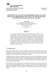
FIGURE 1: A map of the Kenya Rift show<strong>in</strong>g the major<br />
geothermal prospects <strong>and</strong> the Olkaria geothermal field<br />
System<strong>at</strong>ic explor<strong>at</strong>ion was aga<strong>in</strong> began <strong>in</strong> 1970 under the <strong>in</strong>iti<strong>at</strong>ive of the United N<strong>at</strong>ions<br />
Development Programme (UNDP) <strong>and</strong> the Government of Kenya <strong>and</strong> drill<strong>in</strong>g recommenced <strong>in</strong> 1973<br />
after extensive surface work, by the drill<strong>in</strong>g of Olkaria well OW-01. The well proved to have low<br />
temper<strong>at</strong>ures. A second well, well OW-02 was drilled <strong>and</strong> this proved to be more successful. More<br />
drill<strong>in</strong>g was undertaken <strong>and</strong> <strong>in</strong> 1976 a prefeasibility study to utilize geothermal steam for electricity<br />
gener<strong>at</strong>ion was done by SWECO <strong>and</strong> VIRKIR consult<strong>in</strong>g companies. The first unit of 15 MWe was<br />
constructed <strong>in</strong> 1981, the second <strong>in</strong> 1982 <strong>and</strong> the third <strong>in</strong> 1985. After the <strong>in</strong>tial five years of steam<br />
production <strong>in</strong> Olkaria, steam decl<strong>in</strong>e was experienced <strong>in</strong> the steamfield. Make up <strong>wells</strong> were drilled<br />
based on reservoir simul<strong>at</strong>ion studies by (Bodvarsson <strong>and</strong> Preuss, 1987) to <strong>in</strong>crease steam production.<br />
The resource is hosted with<strong>in</strong> the Olkaria volcanic complex which consists of a series of lava domes<br />
<strong>and</strong> ashes, the youngest of which has been d<strong>at</strong>ed <strong>at</strong> ~ 200 years (Clarke et al., 1990). This complex is<br />
estim<strong>at</strong>ed to be 50-80 km 2 . Maximum temper<strong>at</strong>ures <strong>in</strong> deep <strong>wells</strong> <strong>at</strong> Olkaria range between ~ 200°C<br />
<strong>and</strong> ~340°C. The area has been divided <strong>in</strong>to seven sectors for purposes of development (Figure 2).<br />
The sectors are named Olkaria East, Olkaria North East, Olkaria North West, Olkaria South West,<br />
Olkaria South East, Olkaria Central <strong>and</strong> Olkaria Domes. Four power plants are currently <strong>in</strong> oper<strong>at</strong>ion<br />
<strong>in</strong> the Gre<strong>at</strong>er Olkaria Geothermal Area with a total gener<strong>at</strong><strong>in</strong>g capacity of ~ 129 MWe. Two plants<br />
are oper<strong>at</strong>ed by KenGen, i.e. the Olkaria I <strong>and</strong> Olkaria II plants th<strong>at</strong> gener<strong>at</strong>e ~ 115 MWe. The<br />
Olkaria I plant has a capacity of 45 MWe <strong>and</strong> receives its steam supply from the Olkaria East<br />
Production Field. The Olkaria II plant, which is about 3 years old, receives steam from the Olkaria<br />
North East Field. Two <strong>in</strong>dependent power producers gener<strong>at</strong>e about 14 megaw<strong>at</strong>ts of electricity from<br />
6
the Western Sectors. The<br />
Olkaria III plant, oper<strong>at</strong>ed by<br />
Orpower 4 Inc., a subsidiary<br />
of Orm<strong>at</strong> Intern<strong>at</strong>ional<br />
gener<strong>at</strong>es 12 MWe <strong>and</strong> ~ 2<br />
MWe are gener<strong>at</strong>ed by a<br />
flower farm, Oserian<br />
Development Company from<br />
<strong>wells</strong> leased from KenGen.<br />
These two plants are organic<br />
Rank<strong>in</strong>e Orm<strong>at</strong> cycle plants.<br />
Plans are underway to exp<strong>and</strong><br />
the capacity of Olkaria II<br />
plant <strong>in</strong> the Olkaria North<br />
East Field from 70 MWe to<br />
105 MWe by the year 2007<br />
(Mwangi, 2005) <strong>and</strong> the<br />
Orpower 4 Inc. plant from 12<br />
Mwe to 48 Mwe by 2006<br />
(Reshef <strong>and</strong> Citr<strong>in</strong>, 2003).<br />
The geology around Olkaria<br />
has been studied by<br />
North<strong>in</strong>gs (m)<br />
9906000<br />
9905000<br />
9904000<br />
9903000<br />
9902000<br />
9901000<br />
9900000<br />
9899000<br />
Olkaria North West<br />
Olkaria West<br />
193000 194000 195000 196000 197000 198000 199000 200000 201000 202000<br />
East<strong>in</strong>gs (m)<br />
FIGURE 2: Loc<strong>at</strong>ion of the geothermal fields <strong>in</strong> the Gre<strong>at</strong>er<br />
Olkaria Geothermal Area<br />
numerous workers (Naylor, 1972; Brown, 1984, Odongo, 1986; Clarke et al., 1990) <strong>and</strong> is described<br />
as be<strong>in</strong>g characterized by numerous eruptive volcanic centres of Qu<strong>at</strong>ernary age. The geothermal field<br />
is loc<strong>at</strong>ed with<strong>in</strong> a remnant of a caldera complex <strong>in</strong>tersected by N-S rift<strong>in</strong>g faults. These faults are<br />
conduits for numerous eruptions th<strong>at</strong> have formed pumice <strong>and</strong> ryholite domes with<strong>in</strong> the Olkaria<br />
Volcanic complex. The area has a thick cover of pyroclastic ash which is thought to have been<br />
erupted from volcanic centres outside Olkaria namely Suswa <strong>and</strong> Longonot. The Olkaria Volcanic<br />
complex is considered to be bounded by arcu<strong>at</strong>e faults form<strong>in</strong>g a r<strong>in</strong>g or a caldera structure. With<strong>in</strong><br />
this structure a magm<strong>at</strong>ic he<strong>at</strong> source might be represented by <strong>in</strong>trusions <strong>at</strong> depth. Faults <strong>and</strong> fractures<br />
are prom<strong>in</strong>ent <strong>in</strong> the area with general N-S <strong>and</strong> E-W trends but there are also some <strong>in</strong>ferred faults<br />
strik<strong>in</strong>g NW-SE. Other structures <strong>in</strong> the Olkaria area <strong>in</strong>clude the Ol’Njorowa gorge th<strong>at</strong> trends NW-SE<br />
<strong>and</strong> may represent a fault, the Ololbutot fault th<strong>at</strong> trends N-S, the ENE-WSW trend<strong>in</strong>g Olkaria fault,<br />
the WNW-ESE trend<strong>in</strong>g Gorge Farm fault, <strong>and</strong> Olkaria fractures.<br />
The general subsurface str<strong>at</strong>igraphy <strong>at</strong> Olkaria has been described by Brown (1984), Odongo (1986)<br />
<strong>and</strong> Mungania (1992). The rocks <strong>at</strong> the surface are composed of comendites <strong>and</strong> pantellerites <strong>and</strong> these<br />
also occur <strong>in</strong> the upper parts of the subsurface. Omenda (1998) has described the lithostr<strong>at</strong>igraphy of<br />
the Olkaria geothermal area as it is revealed by d<strong>at</strong>a from the geothermal <strong>wells</strong>. These consist broadly<br />
of six ma<strong>in</strong> groups, namely proterozoic “basement” form<strong>at</strong>ions, pre-Mau volcanics, Mau tuffs, Pl<strong>at</strong>eau<br />
trachytes, Olkaria basalt <strong>and</strong> Upper Olkaria volcanics.<br />
Olkaria Central<br />
Field<br />
Olkaria North<br />
East<br />
Olkaria East<br />
Olkaria South<br />
East<br />
Olkaria Domes<br />
2.2 The Reykjanes <strong>and</strong> Svartsengi geothermal fields<br />
The Reykjanes Pen<strong>in</strong>sula is loc<strong>at</strong>ed <strong>in</strong> southwest Icel<strong>and</strong> <strong>and</strong> falls on the cont<strong>in</strong>uous earthquake<br />
epicentre l<strong>in</strong>e extend<strong>in</strong>g through the pen<strong>in</strong>sula <strong>and</strong> further <strong>in</strong>l<strong>and</strong>, reach<strong>in</strong>g several more hightemper<strong>at</strong>ure<br />
geothermal fields (Saemundsson <strong>and</strong> Fridleifsson, 1980). Figure 3 shows a simplified<br />
geological map with the loc<strong>at</strong>ion of the Reykjanes, Svartsengi <strong>and</strong> Nesjavellir fields <strong>and</strong> other hightemper<strong>at</strong>ure<br />
fields <strong>in</strong> Icel<strong>and</strong>.<br />
The Reykjanes geothermal field is one of the six geothermal fields on the Reykjanes Pen<strong>in</strong>sula which<br />
make up the western volcanic zone. Initial development of the geothermal resources <strong>at</strong> Reykjanes<br />
d<strong>at</strong>es back to around 1956, when the first explor<strong>at</strong>ory well was drilled <strong>in</strong> the area. To evalu<strong>at</strong>e the<br />
7
geothermal reservoir for production<br />
of w<strong>at</strong>er <strong>and</strong> steam, extensive field<br />
<strong>in</strong>vestig<strong>at</strong>ions were carried out <strong>in</strong><br />
the period between 1968 <strong>and</strong> 1970.<br />
This effort revealed a hightemper<strong>at</strong>ure<br />
geothermal resource.<br />
The reservoir temper<strong>at</strong>ures are<br />
between 250˚ <strong>and</strong> 320°C. The<br />
str<strong>at</strong>igraphic succession of the<br />
Reykjanes geothermal field,<br />
revealed by drill<strong>in</strong>g, consists of four<br />
ma<strong>in</strong> units, namely an upper str<strong>at</strong>a<br />
(< 120 m) characterised by pillow<br />
basalt <strong>and</strong> on top by subaerial basalt<br />
flows of postglacial age. A more<br />
dom<strong>in</strong>ant sedimentary tuff<br />
form<strong>at</strong>ion above 1000 m <strong>and</strong> more<br />
crystallized basalt form<strong>at</strong>ions <strong>at</strong><br />
gre<strong>at</strong>er depths have been identified<br />
(Tómasson, 1971). Thick<br />
hyaloclastite tuff form<strong>at</strong>ions have<br />
also been identified <strong>at</strong> depth.<br />
FIGURE 3: A simplified geological map with the<br />
loc<strong>at</strong>ions of high-temper<strong>at</strong>ure geothermal fields <strong>in</strong> Icel<strong>and</strong><br />
The <strong>wells</strong> drilled produced high<br />
pressure br<strong>in</strong>e <strong>and</strong> steam. The<br />
development of the Reykjanes<br />
geothermal area was based on an<br />
<strong>in</strong>terest <strong>in</strong> produc<strong>in</strong>g common salt<br />
from br<strong>in</strong>e. A salt production plant<br />
was set up <strong>in</strong> the early 1970’s with<br />
a 0.5 MWe power plant. More<br />
recent surface resistivity studies<br />
(Karlsdόttir, 1997) del<strong>in</strong>e<strong>at</strong>e an area<br />
with an extent of ~ 10 km 2 for the<br />
Reykjanes geothermal system,<br />
whereas surface manifest<strong>at</strong>ions only<br />
cover about 1 km 2 . Acceler<strong>at</strong>ed<br />
drill<strong>in</strong>g was undertaken <strong>in</strong><br />
Reykjanes dur<strong>in</strong>g the period 2002 to<br />
2005 <strong>and</strong> a total of 24 <strong>wells</strong> have<br />
been drilled for electricity<br />
production. A 100 MWe power<br />
plant was commissioned <strong>at</strong><br />
Reykjanes <strong>in</strong> May 2006. The<br />
loc<strong>at</strong>ions of <strong>wells</strong> drilled <strong>in</strong>to the<br />
Reykjanes geothermal field are shown <strong>in</strong> Figure 4.<br />
FIGURE 4: Loc<strong>at</strong>ion of <strong>wells</strong> <strong>in</strong> the<br />
Reykjanes geothermal field<br />
The Svartsengi geothermal field (Figure 5) is loc<strong>at</strong>ed about 15 km to the east of the Reykjanes<br />
geothermal field. Str<strong>at</strong>igraphically it consists of basaltic form<strong>at</strong>ions down to ~300 m depth, followed<br />
by about 300 m thick hyaloclastite series, <strong>and</strong> this is the cap rock of the reservoir. Underne<strong>at</strong>h the<br />
hyaloclastites there are flood basalts. At 1000-1300 m depth <strong>in</strong>trusions become dom<strong>in</strong>ant (Franzson,<br />
1983; 1995). A fissure swarm crosses the reservoir <strong>in</strong> the eastern part of the well field. Surface<br />
manifest<strong>at</strong>ions are limited <strong>and</strong> mostly conf<strong>in</strong>ed to fumaroles <strong>in</strong> a post-glacial lava field. Discharges to<br />
the surface are <strong>in</strong> the form of steam<strong>in</strong>g fumaroles. Reservoir temper<strong>at</strong>ures are uniform between 235<br />
<strong>and</strong> 240°C (Björnsson, 1999). The field supports a geothermal comb<strong>in</strong>ed he<strong>at</strong> <strong>and</strong> power plant with ~<br />
8
46.4 MWe <strong>and</strong> 125 MWt. A<br />
shallow steam zone has evolved<br />
with time <strong>at</strong> Svartsengi <strong>and</strong> this<br />
zone contributes substantially to the<br />
power production. The Svartsengi<br />
geothermal field has an areal extent<br />
of ~ 1 km 2 . Well loc<strong>at</strong>ions <strong>in</strong> the<br />
Svartsengi geothermal field are<br />
shown <strong>in</strong> Figure 5.<br />
2.3 Nesjavellir geothermal field<br />
FIGURE 5: Well loc<strong>at</strong>ions <strong>in</strong> the Svartsengi<br />
geothermal field<br />
The Nesjavellir geothermal field is<br />
loc<strong>at</strong>ed <strong>in</strong> the Hengill hightemper<strong>at</strong>ure<br />
geothermal area which<br />
is situ<strong>at</strong>ed with<strong>in</strong> the active volcanic<br />
zone <strong>in</strong> southwest Icel<strong>and</strong>. This belt<br />
is characterised by several NE-SW<br />
trend<strong>in</strong>g fissure swarms exhibit<strong>in</strong>g<br />
normal faults <strong>and</strong> open fissures.<br />
The Hengill volcano is <strong>in</strong>tersected by one<br />
of these fissure swarms. It is about 50 km<br />
long <strong>and</strong> has a structure of nested grabens.<br />
Faults are very abundant with<strong>in</strong> the fissure<br />
swarm. Several eruptive fissures transect<br />
the centre of Hengill <strong>and</strong> extend to the<br />
northeast by Nesjavellir. Geothermal<br />
surface manifest<strong>at</strong>ions cover an area of<br />
about 40 km 2 (Figure 6).<br />
FIGURE 6: Resistivity map del<strong>in</strong>e<strong>at</strong><strong>in</strong>g the l<strong>at</strong>eral<br />
extent of the Hengill geothermal area<br />
These <strong>in</strong>clude fumaroles, mud pools,<br />
steam<strong>in</strong>g ground <strong>and</strong> acid surface<br />
alter<strong>at</strong>ion as well as hot spr<strong>in</strong>gs. From the<br />
Hengill there is a l<strong>in</strong>eament of surface<br />
manifest<strong>at</strong>ions extend<strong>in</strong>g towards the SE<br />
<strong>in</strong>to the Hveragerdi centre form<strong>in</strong>g a<br />
cont<strong>in</strong>u<strong>at</strong>ion of the transcurrent faults<br />
dissect<strong>in</strong>g the ma<strong>in</strong> fissure swarm.<br />
Surface surveys for geothermal<br />
explor<strong>at</strong>ion <strong>in</strong> the Hengill area started <strong>in</strong><br />
the 1940´s. Drill<strong>in</strong>g started <strong>in</strong> the l<strong>at</strong>e<br />
1950’s <strong>and</strong> early 1960’s. In 1990 the<br />
geothermal resource <strong>at</strong> Nesjavellir was<br />
harnessed for district he<strong>at</strong><strong>in</strong>g <strong>in</strong><br />
Reykjavík. This <strong>in</strong>volved he<strong>at</strong><strong>in</strong>g w<strong>at</strong>er<br />
us<strong>in</strong>g he<strong>at</strong> exchangers. The geothermal w<strong>at</strong>er could not be used directly due it its chemical content. At<br />
the time it was decided to harness the geothermal resource <strong>at</strong> Nesjavellir, 14 production <strong>wells</strong> had<br />
been drilled <strong>and</strong> all but one were successful (Gunnarsson et al., 1992). Wells drilled <strong>at</strong> Nesjavellir<br />
range <strong>in</strong> depth from 1,000 to 2,200 meters <strong>and</strong> the highest temper<strong>at</strong>ures recorded are > 380 ˚ C<br />
(Gunnarsson et al., 1992).<br />
The str<strong>at</strong>igraphy <strong>at</strong> Nesjavellir as revealed by drill<strong>in</strong>g, consists ma<strong>in</strong>ly of volcanic rocks. These are<br />
divided <strong>in</strong>to extrusive <strong>and</strong> <strong>in</strong>trusive rock form<strong>at</strong>ions. The extrusive rocks consist ma<strong>in</strong>ly of<br />
9
hyaloclastites <strong>and</strong> basalt lavas. Nouralie (2000) described the str<strong>at</strong>igraphy as consist<strong>in</strong>g ma<strong>in</strong>ly of<br />
hyaloclastites <strong>in</strong> the shallower parts of the system, < 730 m. In the deeper parts, > 730 m, basalt lavas<br />
are predom<strong>in</strong>ant. The hyaloclastites are ma<strong>in</strong>ly volcanics which are divided <strong>in</strong>to four groups; Tuffs,<br />
Breccia lavas, Basaltic breccias <strong>and</strong> Pillow lavas. The <strong>in</strong>trusives are predom<strong>in</strong>antly basalts <strong>and</strong> are<br />
found <strong>in</strong> the deeper parts of the system.<br />
The thermal plant was <strong>in</strong>itially commissioned to gener<strong>at</strong>e about 100 MWt of he<strong>at</strong>, but has s<strong>in</strong>ce been<br />
progressively exp<strong>and</strong>ed <strong>in</strong> t<strong>and</strong>em with better utiliz<strong>at</strong>ion of the resource. In 1991 the capacity of the<br />
thermal plant was exp<strong>and</strong>ed to 150 MWt <strong>and</strong> <strong>in</strong> 1998 a further 250 MWt <strong>and</strong> 60 MWe were added.<br />
This started the Nesjavellir co-gener<strong>at</strong>ion plant which has two ma<strong>in</strong> functions; to produce electricity<br />
from geothermal steam <strong>and</strong> to he<strong>at</strong> cold ground w<strong>at</strong>er for district he<strong>at</strong><strong>in</strong>g. Currently, the <strong>in</strong>stalled<br />
capacity for electricity gener<strong>at</strong>ion is 120 MWe from four steam cycle turb<strong>in</strong>es of 30 MWe each <strong>and</strong><br />
290 MWt. The Nesjavellir geothermal field with well loc<strong>at</strong>ions is shown <strong>in</strong> Figure 7.<br />
FIGURE 7: Well loc<strong>at</strong>ions <strong>in</strong> the Nesjavellir<br />
geothermal field<br />
10
3. SAMPLING AND ANALYSIS<br />
3.1 Sample collection<br />
At Reykjanes, Svartsengi <strong>and</strong> Nesjavellir,<strong>and</strong> other Icel<strong>and</strong>ic fields both steam <strong>and</strong> w<strong>at</strong>er are collected<br />
<strong>at</strong> the same pressure us<strong>in</strong>g a Webre separ<strong>at</strong>or.<br />
At Olkaria various<br />
methods have been<br />
applied to collect<br />
samples of w<strong>at</strong>er <strong>and</strong><br />
steam from the wetsteam<br />
well discharges.<br />
Some of these methods<br />
are described by Ellis<br />
<strong>and</strong> Mahon (1977) <strong>and</strong><br />
Arnόrsson et al.<br />
(2000). One of the<br />
methods <strong>in</strong>volves the<br />
use of a Webre<br />
separ<strong>at</strong>or, which is<br />
connected to a twophase<br />
pipel<strong>in</strong>e th<strong>at</strong><br />
conveys the total<br />
discharge to an<br />
<strong>at</strong>mospheric silencer<br />
(Figure 8).<br />
By this method<br />
sampl<strong>in</strong>g <strong>in</strong>volves the<br />
collection of steam samples<br />
under pressure from the<br />
Webre separ<strong>at</strong>or <strong>and</strong> w<strong>at</strong>er<br />
from the weirbox. Steam<br />
samples collected <strong>in</strong> this<br />
way are mostly from the<br />
<strong>wells</strong> th<strong>at</strong> are be<strong>in</strong>g<br />
discharge tested or<br />
explor<strong>at</strong>ion <strong>wells</strong> <strong>and</strong> a<br />
number of production <strong>wells</strong><br />
<strong>in</strong> the Olkaria East<br />
production field th<strong>at</strong> share a<br />
common separ<strong>at</strong>or st<strong>at</strong>ion.<br />
In the Olkaria North East<br />
Field which produces steam<br />
for the Olkaria II power<br />
plant sampl<strong>in</strong>g of steam <strong>and</strong><br />
w<strong>at</strong>er will be carried out by<br />
FIGURE 8: Steam is collected from a Webre separ<strong>at</strong>or on a two-phase<br />
pipel<strong>in</strong>e upstream from the <strong>at</strong>mospheric silencer <strong>and</strong> w<strong>at</strong>er from the<br />
weirbox, a part of the steam (X w-a ) discharged from the <strong>at</strong>mospheric<br />
silencer is not sampled, i.e. the steam which forms by depressuris<strong>at</strong>ion<br />
boil<strong>in</strong>g from the pressure <strong>in</strong> Webre separ<strong>at</strong>or to <strong>at</strong>mosphere<br />
FIGURE 9: Steam is collected from the steam separ<strong>at</strong>or <strong>and</strong> w<strong>at</strong>er<br />
from the weirbox, the steam (X s-a ) discharged from the <strong>at</strong>mospheric<br />
silencer is not sampled. This steam forms by depressuris<strong>at</strong>ion<br />
boil<strong>in</strong>g from pressure <strong>in</strong> the steam separ<strong>at</strong>or<br />
to <strong>at</strong>mospheric pressure<br />
the use of a Webre separ<strong>at</strong>or. For production <strong>wells</strong> <strong>in</strong> the Olkaria East Production Field, steam<br />
samples were collected from the steam l<strong>in</strong>e downstream of the wellhead separ<strong>at</strong>or us<strong>in</strong>g a sta<strong>in</strong>less<br />
steel tub<strong>in</strong>g (Figure 9).<br />
W<strong>at</strong>er samples were collected from the weirbox. A fraction of the discharge is not sampled when the<br />
w<strong>at</strong>er <strong>and</strong> steam samples are collected <strong>at</strong> different pressures as expla<strong>in</strong>ed <strong>in</strong> Figs. 8 <strong>and</strong> 9. As<br />
expla<strong>in</strong>ed <strong>in</strong> section 5.2 below, it is assumed when calcul<strong>at</strong><strong>in</strong>g aquifer w<strong>at</strong>er composition th<strong>at</strong> the<br />
11
secondary steam not sampled is free of gas. When collect<strong>in</strong>g w<strong>at</strong>er <strong>and</strong> steam samples from wet-steam<br />
well discharges us<strong>in</strong>g a Webre separ<strong>at</strong>or good phase separ<strong>at</strong>ion is essential. Pipes from <strong>wells</strong> with low<br />
discharge enthalpy (less than 900 kJ/ kg) may experience slug flow <strong>and</strong> separ<strong>at</strong>ion can be a problem.<br />
When the steam fraction is high, i.e. the discharge enthalpy approaches th<strong>at</strong> of dry steam (above 2500<br />
kJ/kg), the w<strong>at</strong>er flow r<strong>at</strong>e <strong>in</strong>to the Webre separ<strong>at</strong>or may not be sufficient for collect<strong>in</strong>g a steam free<br />
w<strong>at</strong>er sample <strong>and</strong> when this is the case, the only altern<strong>at</strong>ive may be the collection of a w<strong>at</strong>er sample <strong>at</strong><br />
<strong>at</strong>mospheric pressure (from the weirbox) or from a wellhead steam separ<strong>at</strong>or.<br />
The sampl<strong>in</strong>g methods <strong>in</strong> case 3 were applied <strong>in</strong> Olkaria s<strong>in</strong>ce the <strong>in</strong>ception of the Olkaria East<br />
Production Field, but may change with total re-<strong>in</strong>jection of separ<strong>at</strong>ed w<strong>at</strong>er be<strong>in</strong>g a requirement <strong>in</strong><br />
current power development schemes. This will require <strong>in</strong> the future th<strong>at</strong> both w<strong>at</strong>er <strong>and</strong> steam are<br />
collected <strong>at</strong> the same pressure.<br />
Steam samples were collected <strong>in</strong>to two gas-sampl<strong>in</strong>g flasks, which had been evacu<strong>at</strong>ed <strong>in</strong> the<br />
labor<strong>at</strong>ory after <strong>in</strong>troduc<strong>in</strong>g 10 ml of freshly prepared 50 % w/w KOH <strong>in</strong> the case of Olkaria <strong>and</strong> the<br />
others 50 ml of 4M NaOH solution. The gas bulbs were weighed before <strong>and</strong> after sampl<strong>in</strong>g to record<br />
the amount of steam condens<strong>at</strong>e collected. W<strong>at</strong>er samples were filtered through 0.2 µm millipore<br />
membrane (cellulose acet<strong>at</strong>e) <strong>in</strong>to low density polyethylene bottles us<strong>in</strong>g a propylene filter holder. The<br />
entire filtr<strong>at</strong>ion appar<strong>at</strong>us was thoroughly r<strong>in</strong>sed with deionised w<strong>at</strong>er before collect<strong>in</strong>g a sample. A<br />
100 ml sample was acidified with 1 ml of suprapure concentr<strong>at</strong>ed HNO 3 for ICP-AES analysis for Si,<br />
B, Na, K, Ca, Mg, Al, Fe <strong>and</strong> S(SO 4 ). Another 100 ml sample was collected for SO 4 analysis to which<br />
1 ml of 1% z<strong>in</strong>c acet<strong>at</strong>e solution was added to remove H 2 S. A third 100 ml sample was collected <strong>and</strong><br />
for the determ<strong>in</strong><strong>at</strong>ion of Cl <strong>and</strong> F by ion chrom<strong>at</strong>ography only, 250 ml glass bottles with special caps<br />
th<strong>at</strong> prevent entrapment of air were used to collect w<strong>at</strong>er samples for the determ<strong>in</strong><strong>at</strong>ion of pH <strong>and</strong> total<br />
carbon<strong>at</strong>e carbon. These two w<strong>at</strong>er samples, which were not filtered, were cooled to < 40˚C by pass<strong>in</strong>g<br />
them through a sta<strong>in</strong>less steel cool<strong>in</strong>g coil to prevent degass<strong>in</strong>g of the sample th<strong>at</strong> would otherwise<br />
occur upon storage due to thermal contraction of the w<strong>at</strong>er prior to analysis.<br />
3.2 Analysis of w<strong>at</strong>er <strong>and</strong> steam samples<br />
Steam samples were analysed for CO 2 , H 2 S, H 2 , CH 4 , N 2 , <strong>and</strong> O 2 . The non-condensable gases (H 2 ,<br />
CH 4 , N 2 <strong>and</strong> O 2 ) were analysed by gas chrom<strong>at</strong>ography, while CO 2 <strong>and</strong> H 2 S were determ<strong>in</strong>ed by<br />
titr<strong>at</strong>ion of the NaOH-condens<strong>at</strong>e solution with 0.1 M HCl <strong>and</strong> 0.001M Hg(CH 3 COO) 2 st<strong>and</strong>ard<br />
solutions respectively (Arnόrsson et al., 2000). Both CO 2 <strong>and</strong> H 2 S disssolve quantit<strong>at</strong>ively <strong>in</strong> the<br />
alkal<strong>in</strong>e solutions. In this way, the non-condensable gases become concentr<strong>at</strong>ed <strong>in</strong> the gas phase<br />
mak<strong>in</strong>g analysis for them more precise.<br />
In w<strong>at</strong>er samples, H 2 S was analysed for <strong>in</strong> the same way as <strong>in</strong> steam samples <strong>and</strong> determ<strong>in</strong>ed on site to<br />
obta<strong>in</strong> its own concentr<strong>at</strong>ion <strong>and</strong> aga<strong>in</strong> <strong>at</strong> the time of the total carbon<strong>at</strong>e (TCC) titr<strong>at</strong>ion for the<br />
purpose of subtraction. Total carbon<strong>at</strong>e carbon (TCC) <strong>and</strong> pH were determ<strong>in</strong>ed <strong>in</strong> the labor<strong>at</strong>ory as<br />
soon as possible (1-2 hours) after sampl<strong>in</strong>g by titr<strong>at</strong>ion with 0.1 M HCl. Interference from other bases<br />
was corrected for by back titr<strong>at</strong>ion with 0.1M NaOH follow<strong>in</strong>g the bubbl<strong>in</strong>g of N 2 through the solution<br />
to remove CO 2 <strong>and</strong> H 2 S (Arnόrsson et al., 2000). By this method, the difference of the two titr<strong>at</strong>ions<br />
gives the sum of TCC <strong>and</strong> total sulphide. The value for TCC was obta<strong>in</strong>ed by difference from<br />
<strong>in</strong>dependent measurements of total sulphide. The major aqueous c<strong>at</strong>ions (Na, K, Ca, Mg, Al, Fe,) plus<br />
Si, SO 4 (as S) <strong>and</strong> B were analysed for on a Thermo Jarrel Ash ICP-AES. Ion chrom<strong>at</strong>ography was<br />
used to determ<strong>in</strong>e SO 4 , Cl, F.<br />
12
4. FLUID COMPOSITIONS<br />
The composition of fluid discharged from <strong>wells</strong> <strong>in</strong> the four areas is quite variable (Tables 1a <strong>and</strong> 1b <strong>in</strong><br />
Appendix A). These are taken from different sources, namely Olkaria (Kar<strong>in</strong>githi, 2002), Reykjanes<br />
<strong>and</strong> Svartsengi (<strong>Orkustofnun</strong> d<strong>at</strong>a base, Ármannsson, H., 2005, pers. comm.) <strong>and</strong> Nesjavellir (Giroud,<br />
N., 2006, pers. comm.). With<strong>in</strong> the Olkaria geothermal field the composition of discharged liquid<br />
w<strong>at</strong>er <strong>and</strong> steam is varied but less so <strong>at</strong> Nesjavellir. In Svartsengi <strong>and</strong> Reykjanes, fluid compositions<br />
are quite homogenous.<br />
The fluid composition from<br />
the Gre<strong>at</strong>er Olkaria<br />
Geothermal Area, Reykjanes,<br />
Svartsengi <strong>and</strong> Nesjavellir is<br />
plotted on a Cl-SO 4 -HCO 3<br />
ternary diagram (Figure 10).<br />
The discharged w<strong>at</strong>ers <strong>in</strong> the<br />
Olkaria West Field are<br />
predom<strong>in</strong>antly near neutral<br />
sodium-bicarbon<strong>at</strong>e w<strong>at</strong>ers,<br />
while those of from the<br />
Olkaria East <strong>and</strong> Olkaria<br />
North East fields are dilute,<br />
near neutral-pH chloride<br />
w<strong>at</strong>ers. The w<strong>at</strong>ers from<br />
Reykjanes <strong>and</strong> Svartsengi,<br />
plot <strong>at</strong> the chloride apex.<br />
W<strong>at</strong>ers from Nesjavellir are<br />
rel<strong>at</strong>ively enriched <strong>in</strong><br />
chloride, like the Olkaria East<br />
w<strong>at</strong>ers. W<strong>at</strong>ers discharged<br />
from <strong>wells</strong> <strong>in</strong> Olkaria Central<br />
<strong>and</strong> Olkaria Domes are<br />
ma<strong>in</strong>ly mixed sodium<br />
bicarbon<strong>at</strong>e - sodium chloride<br />
w<strong>at</strong>ers.<br />
W<strong>at</strong>ers discharged from the<br />
weirbox of <strong>wells</strong> <strong>at</strong> Olkaria<br />
have chloride concentr<strong>at</strong>ions<br />
rang<strong>in</strong>g from ~50 ppm to ~<br />
4000 ppm. The silica content<br />
varies between ~ 350 ppm<br />
<strong>and</strong> ~ 1000 ppm SiO 2 . The<br />
Olkaria East<br />
Olkaria North East<br />
Olkaria West<br />
Olkaria Central<br />
Olkaria Domes<br />
Svartsengi<br />
Reykjanes<br />
Nesjavellir<br />
75<br />
50<br />
100<br />
0<br />
SO4<br />
HCO3<br />
0 25 50 75 100<br />
FIGURE 10: Cl-SO 4 - HCO 3 ternary plot for fluids from<br />
different sectors of Olkaria, Reykjanes Svartsengi<br />
<strong>and</strong> Nesjavellir geothermal fields<br />
total carbon<strong>at</strong>e concentr<strong>at</strong>ion is highly variable rang<strong>in</strong>g from < 100 ppm to almost 2500 ppm as CO 2 .<br />
Gas content <strong>in</strong> steam, especially carbon dioxide (CO 2 ) <strong>and</strong> hydrogen sulphide (H 2 S) is generally low<br />
<strong>in</strong> the fluids of Olkaria except fluid discharged from Olkaria West which has a very high CO 2 gas<br />
content <strong>in</strong> steam ~ 10,000 mmoles/kg (Table 1a, Appendix A). Nitrogen content <strong>in</strong> steam is rel<strong>at</strong>ively<br />
high, but highest for well discharges <strong>in</strong> Olkaria Domes <strong>and</strong> Olkaria West which could suggest there is<br />
a high contribution of flow from the surface to the fluids.<br />
At Reykjanes the w<strong>at</strong>er <strong>in</strong> the reservoir is sea w<strong>at</strong>er (Björnsson et al., 1972). The composition of the<br />
parent sea w<strong>at</strong>er has been modified by reactions with the basaltic rock. Slight loss of sodium has<br />
occurred but slight enrichment <strong>in</strong> silica, potassium <strong>and</strong> calcium, <strong>and</strong> almost complete depletion <strong>in</strong><br />
sulph<strong>at</strong>e <strong>and</strong> magnesium (Bjarnason, 1984). The chloride content of the geothermal w<strong>at</strong>er is close to<br />
25<br />
0<br />
Cl<br />
100<br />
Cl<br />
SO4 HCO3<br />
75<br />
50<br />
25<br />
13
th<strong>at</strong> of sea w<strong>at</strong>er. Carbon dioxide is the most abundant gas, > 95 %, correspond<strong>in</strong>g to ~2000 ppm <strong>in</strong><br />
the reservoir fluid. Compared to Olkaria, H 2 S <strong>and</strong> H 2 concentr<strong>at</strong>ions are rel<strong>at</strong>ively low.<br />
The reservoir w<strong>at</strong>er <strong>in</strong> Svartsengi is two-thirds sea w<strong>at</strong>er <strong>and</strong> one-third meteoric w<strong>at</strong>er by orig<strong>in</strong> as<br />
<strong>in</strong>dic<strong>at</strong>ed by its Cl content. This parent w<strong>at</strong>er has also been modified by reactions with the basaltic<br />
rock <strong>in</strong> a fashion similar to the w<strong>at</strong>er <strong>at</strong> Reykjanes. As <strong>at</strong> Reykjanes, CO 2 gas makes up the major gas<br />
<strong>in</strong> the steam , ~ 95 vol.% . The concentr<strong>at</strong>ions of H 2 S <strong>and</strong> H 2 are low rel<strong>at</strong>ive to Olkaria.<br />
W<strong>at</strong>er discharged from <strong>wells</strong> <strong>at</strong> Nesjavellir, which is meteoric by orig<strong>in</strong> is very low <strong>in</strong> dissolved solids<br />
(Table 1 b <strong>in</strong> Appendix A). Silica is the most abundant dissolved solid. The chloride content is 100-<br />
200 ppm. The cause of the low Cl concentr<strong>at</strong>ions is the low Cl content of the basalts with which the<br />
w<strong>at</strong>er has <strong>in</strong>teracted. Carbon dioxide is the major gas component <strong>in</strong> steam. Hydrogen sulphide <strong>and</strong><br />
hydrogen concentr<strong>at</strong>ions are rel<strong>at</strong>ively elev<strong>at</strong>ed compared to well fluids <strong>at</strong> Olkaria, Reykjanes <strong>and</strong><br />
Svartsengi.<br />
14
5. CALCULATION OF AQUIFER FLUID COMPOSITIONS<br />
5.1 Discharge enthalpy of <strong>wells</strong><br />
Production <strong>wells</strong> <strong>at</strong> Olkaria <strong>and</strong> Nesjavellir typically have “excess” enthalpy (Table 1a <strong>and</strong> b of<br />
Appendix A), i.e. the enthalpy of the fluid discharges is higher than th<strong>at</strong> of steam s<strong>at</strong>ur<strong>at</strong>ed w<strong>at</strong>er <strong>at</strong> the<br />
respective aquifer temper<strong>at</strong>ure. At Svartsengi production <strong>wells</strong> have liquid enthalpy, i.e. their enthalpy<br />
equals th<strong>at</strong> of liquid w<strong>at</strong>er <strong>at</strong> the temper<strong>at</strong>ure of produc<strong>in</strong>g aquifers except for shallow <strong>wells</strong> which<br />
have been drilled <strong>in</strong>to the steam cap th<strong>at</strong> has formed on top of the liquid dom<strong>in</strong><strong>at</strong>ed reservoir as a<br />
consequence of reservoir pressure decl<strong>in</strong>e follow<strong>in</strong>g exploit<strong>at</strong>ion. At Reykjanes some <strong>wells</strong> have<br />
liquid enthalpy <strong>and</strong> some excess enthalpy. Excess enthalpy of <strong>wells</strong> poses problems <strong>in</strong> calcul<strong>at</strong><strong>in</strong>g<br />
component concentr<strong>at</strong>ions <strong>in</strong> the <strong>in</strong>itial aquifer fluid from analytical d<strong>at</strong>a on samples of liquid w<strong>at</strong>er<br />
<strong>and</strong> steam collected <strong>at</strong> the wellhead.<br />
Excess well discharge enthalpy <strong>in</strong> the Olkaria East Production Field may be produced by withdrawal<br />
of fluid from the steam zone <strong>and</strong> the underly<strong>in</strong>g liquid dom<strong>in</strong><strong>at</strong>ed reservoir. In general it may,<br />
however, be produced by processes occurr<strong>in</strong>g <strong>in</strong> the depressuriz<strong>at</strong>ion zone around discharg<strong>in</strong>g <strong>wells</strong><br />
where extensive boil<strong>in</strong>g occurs. These processes are: (1) he<strong>at</strong> transfer from the aquifer rock to the fluid<br />
th<strong>at</strong> migr<strong>at</strong>es through the depressuriz<strong>at</strong>ion zone <strong>and</strong> (2) separ<strong>at</strong>ion to the rel<strong>at</strong>ive permeabilities of the<br />
liquid w<strong>at</strong>er <strong>and</strong> steam phases <strong>and</strong> their different flow<strong>in</strong>g properties (e.g. Horne et al., 2000; Pruess,<br />
2002; Li <strong>and</strong> Horne, 2004). Transfer of he<strong>at</strong> from the aquifer rock to the fluid flow<strong>in</strong>g through the<br />
depressuriz<strong>at</strong>ion zone <strong>in</strong>to <strong>wells</strong> tends to occur because depressuriz<strong>at</strong>ion leads to cool<strong>in</strong>g of the fluid<br />
by boil<strong>in</strong>g <strong>and</strong> hence gener<strong>at</strong>es a positive temper<strong>at</strong>ure gradient between the aquifer rock <strong>and</strong> this fluid.<br />
Production of excess well discharge enthalpy by phase segreg<strong>at</strong>ion tends to occur because the liquid<br />
w<strong>at</strong>er is partially reta<strong>in</strong>ed <strong>in</strong> the aquifer as a result of capillary forces, while the steam flows <strong>in</strong>to <strong>wells</strong>.<br />
“Excess enthalpy” may be due to the presence of significant steam fraction <strong>in</strong> the <strong>in</strong>itial aquifer fluid.<br />
Specifically <strong>at</strong> Olkaria, the “excess enthalpy” could, <strong>at</strong> least be due to contribution from the shallow<br />
steam zone which overlies the liquid dom<strong>in</strong><strong>at</strong>ed zone. The discharge could also be from multiple<br />
feeds, shallow vapour-dom<strong>in</strong><strong>at</strong>ed <strong>and</strong> deep liquid-dom<strong>in</strong><strong>at</strong>ed feeds.<br />
If the excess discharge enthalpy is solely caused by conductive he<strong>at</strong> transfer from the aquifer to the<br />
fluid flow<strong>in</strong>g <strong>in</strong>to the well (conductive he<strong>at</strong> transfer model), the composition of the total well<br />
discharge will be the same as th<strong>at</strong> of the aquifer fluid. Conserv<strong>at</strong>ive components, such as Cl, which are<br />
concentr<strong>at</strong>ed <strong>in</strong> the liquid w<strong>at</strong>er phase, will <strong>in</strong>crease <strong>in</strong> the phase <strong>and</strong> approach <strong>in</strong>f<strong>in</strong>ity when the<br />
discharge enthalpy approaches th<strong>at</strong> of dry steam. On the other h<strong>and</strong>, if phase segreg<strong>at</strong>ion were the<br />
cause of the excess discharge enthalpy (phase segreg<strong>at</strong>ion model), Cl concentr<strong>at</strong>ions <strong>in</strong> the liquid<br />
w<strong>at</strong>er would be about constant but they would approach zero <strong>in</strong> the total discharge when the discharge<br />
enthalpy approached th<strong>at</strong> of dry steam.<br />
When excess well discharge enthalpy is produced by the conductive he<strong>at</strong> transfer model, total well<br />
discharge compositions can be used to calcul<strong>at</strong>e quartz <strong>and</strong> Na/K geothermometer temper<strong>at</strong>ures. This<br />
is, however, not valid if the cause of the excess enthalpy is phase segreg<strong>at</strong>ion. Total discharge<br />
composition will yield low quartz equilibrium temper<strong>at</strong>ures, <strong>and</strong> the lower the higher the discharge<br />
enthalpy. The Na/K geothermometer, which is based on an elemental r<strong>at</strong>io, is <strong>in</strong>dependent of which<br />
model is responsible for the excess enthalpy.<br />
Calcul<strong>at</strong>ed temper<strong>at</strong>ures of tqtz <strong>and</strong> tNaK from the equ<strong>at</strong>ions given by Arnórsson (2000 a), for some<br />
of the selected <strong>wells</strong> <strong>at</strong> Olkaria, Reykjanes, Svartsengi <strong>and</strong> Nesjavellir are presented <strong>in</strong> Table 3 of<br />
Appendix A. At Olkaria, quartz equilibrium <strong>and</strong> Na/K geothermometer temper<strong>at</strong>ures compare well<br />
when us<strong>in</strong>g the segreg<strong>at</strong>ion model to calcul<strong>at</strong>e the aquifer w<strong>at</strong>er compositions (Kar<strong>in</strong>githi et al., 2006).<br />
This also applies to Nesjavellir (Figure 11).<br />
For the present study, therefore, the phase segreg<strong>at</strong>ion model <strong>and</strong> the average of the quartz <strong>and</strong> the Na-<br />
K geothermometer results were used to represent aquifer temper<strong>at</strong>ure of <strong>wells</strong> <strong>at</strong> Olkaria <strong>and</strong><br />
Nesjavellir. At Reykjanes, Na/K temper<strong>at</strong>ures are somewh<strong>at</strong> lower than those of quartz. The cause is<br />
15
considered to be limited supply of K to the<br />
w<strong>at</strong>er. The geothermal seaw<strong>at</strong>er has about<br />
four times the K concentr<strong>at</strong>ion of seaw<strong>at</strong>er<br />
<strong>and</strong> the basaltic rock with which the<br />
geothermal seaw<strong>at</strong>er has reacted is very<br />
low <strong>in</strong> K. At Reykjanes, measured<br />
downhole temper<strong>at</strong>ures were selected<br />
tak<strong>in</strong>g total well discharge compositions to<br />
represent the aquifer w<strong>at</strong>er compositions.<br />
The enthalpy of the <strong>wells</strong> represents pure<br />
liquid <strong>and</strong> it is assumed they follow the<br />
boil<strong>in</strong>g po<strong>in</strong>t with depth curve. In the<br />
sub-boil<strong>in</strong>g reservoir <strong>at</strong> Svartsengi,<br />
measured temper<strong>at</strong>ures downhole were<br />
selected. They compare well with both<br />
quartz equilibrium <strong>and</strong> Na/K<br />
geothermometer results.<br />
tqtz - t NaK (°C)<br />
120<br />
80<br />
40<br />
0<br />
-40<br />
FIGURE 11: Rel<strong>at</strong>ionship between<br />
tqtz vs. tNaK equilibrium<br />
Enthalpy vs tqtz-tNaK difference<br />
OW-20<br />
OW-19<br />
OW-23<br />
OW-25<br />
OW-714<br />
1600 1800 2000 2200 2400 2600 2800<br />
Enthalpy kJ/Kg<br />
FIGURE 12: Difference between tNa/K <strong>and</strong> tqtz vs.<br />
various enthalpies for selected number of <strong>wells</strong><br />
from Olkaria East <strong>and</strong> Olkaria North East<br />
A number of selected <strong>wells</strong> <strong>in</strong> Olkaria,<br />
Reykjanes <strong>and</strong> Nesjavellir <strong>in</strong>dic<strong>at</strong>e tqtz<br />
temper<strong>at</strong>ures th<strong>at</strong> are higher than tNaK. In<br />
Reykjanes as expla<strong>in</strong>ed above, the<br />
difference could be due to limited supply<br />
of potassium <strong>in</strong> the w<strong>at</strong>er. In the case of a<br />
number of selected <strong>wells</strong> <strong>in</strong> Olkaria, <strong>and</strong><br />
Nesjavellir, this could be caused by the<br />
model selected to calcul<strong>at</strong>e the aquifer<br />
w<strong>at</strong>er composition which could be wrong.<br />
The orig<strong>in</strong> of the fluid composition could<br />
be due to conductive he<strong>at</strong> transfer<br />
from the aquifer rock to the fluid<br />
flow<strong>in</strong>g <strong>in</strong>to <strong>wells</strong> which<br />
contributes to the discharge<br />
enthalpy. Aquifer w<strong>at</strong>er<br />
composition may not be the source<br />
of the error. Other errors may arise<br />
from the selection of discharge<br />
enthalpy which is affected by<br />
measurements of w<strong>at</strong>er flow.<br />
Wells <strong>in</strong> the Olkaria Domes sector<br />
have enthalpies close to those of<br />
liquid enthalpy <strong>and</strong> tqtz is higher<br />
than tNaK. A similar observ<strong>at</strong>ion<br />
is made for <strong>wells</strong> <strong>in</strong> the Olkaria<br />
West sector (Table 3, Appendix A).<br />
This difference may not be<br />
expla<strong>in</strong>ed by the selected discharge<br />
enthalpy. A different temper<strong>at</strong>ure<br />
model may be applicable for<br />
temper<strong>at</strong>ure selection.<br />
Figure 12 shows enthalpy vs<br />
temper<strong>at</strong>ure difference between tqtz<br />
<strong>and</strong> tNaK for a number of selected<br />
<strong>wells</strong> <strong>in</strong> Olkaria. As enthalpy<br />
16
<strong>in</strong>creases the difference <strong>in</strong> tNaK – tqtz <strong>in</strong>creases because the enthalpy affects the value of calcul<strong>at</strong>ed<br />
SiO 2 concentr<strong>at</strong>ion <strong>in</strong> the liquid w<strong>at</strong>er phase.<br />
The temper<strong>at</strong>ure difference between tNaK <strong>and</strong> tqtz <strong>in</strong> <strong>wells</strong> OW 709 <strong>and</strong> OW-202 is high <strong>and</strong> these<br />
st<strong>and</strong> out (Table 3 Appendix A). The high tNaK <strong>and</strong> tqtz differences for the fluids of <strong>wells</strong> OW-709<br />
<strong>and</strong> OW-202 cannot be expla<strong>in</strong>ed by enthalpy effects, but possibly by dilution of geothermal w<strong>at</strong>er.<br />
Such dilution would not affect Na/K temper<strong>at</strong>ures but yield low quartz equilibrium temper<strong>at</strong>ures<br />
rel<strong>at</strong>ive to the temper<strong>at</strong>ure of the undiluted w<strong>at</strong>er. The high pH of the aquifer fluids of these two <strong>wells</strong><br />
could affect the tqtz due to enhanced dissoci<strong>at</strong>ion of the unionised silica, but this does not seem to be<br />
the case.<br />
Another well with a high temper<strong>at</strong>ure difference between tNaK <strong>and</strong> tqtz is well OW-34. The well is<br />
much higher <strong>in</strong> m<strong>in</strong>eral content <strong>and</strong> its enthalpy is high ~2672 kJ/Kg. High enthalpy affects silica<br />
concentr<strong>at</strong>ions. This could probably contribute to the large differences <strong>in</strong> tNaK <strong>and</strong> tqtz temper<strong>at</strong>ures.<br />
5.2 Calcul<strong>at</strong>ion of gas concentr<strong>at</strong>ions <strong>in</strong> steam <strong>at</strong> <strong>at</strong>mospheric pressure<br />
The WATCH chemical speci<strong>at</strong>ion program (Arnόrsson et al., 1982), version 2.1A (Bjarnason, 1994),<br />
was used to calcul<strong>at</strong>e aquifer w<strong>at</strong>er composition <strong>and</strong> aqueous <strong>species</strong> distribution from d<strong>at</strong>a on liquid<br />
w<strong>at</strong>er <strong>and</strong> steam sample composition <strong>at</strong> wellhead conditions. This program assumes th<strong>at</strong> both types of<br />
samples are collected <strong>at</strong> the same pressure. As expla<strong>in</strong>ed <strong>in</strong> section 3, the Olkaria well samples were<br />
collected differently <strong>and</strong> therefore gas concentr<strong>at</strong>ion <strong>in</strong> steam <strong>at</strong> <strong>at</strong>mospheric pressure was calcul<strong>at</strong>ed<br />
assum<strong>in</strong>g th<strong>at</strong> the secondary steam not sampled is free of gas. Two cases need to be condsidered<br />
(Arnόrsson <strong>and</strong> Stefansson, 2005). One is represented by steam samples collected from the wellhead<br />
steam separ<strong>at</strong>or <strong>and</strong> the other when there was no wellhead separ<strong>at</strong>or <strong>and</strong> the steam samples were<br />
collected with the aid of a Webre separ<strong>at</strong>or, which is connected to the two-phase pipel<strong>in</strong>e discharg<strong>in</strong>g<br />
<strong>in</strong>to the <strong>at</strong>mospheric silencer.<br />
Case 1: Steam samples collected from the wellhead steam separ<strong>at</strong>or separ<strong>at</strong><strong>in</strong>g the total discharge.<br />
The total steam fraction discharged from the well <strong>at</strong> <strong>at</strong>mospheric pressure accord<strong>in</strong>g to this case is X al ,<br />
rel<strong>at</strong>ive to the total well discharge is given by:<br />
X<br />
al<br />
s<br />
s−a<br />
= X + X<br />
5.2.1<br />
Here, X s , represents the steam fraction <strong>in</strong> the wellhead separ<strong>at</strong>or. The fraction of steam which forms<br />
by depressuris<strong>at</strong>ion boil<strong>in</strong>g of the separ<strong>at</strong>ed w<strong>at</strong>er flow<strong>in</strong>g from the wellhead steam separ<strong>at</strong>or to the<br />
<strong>at</strong>mospheric silencer, X s-a , rel<strong>at</strong>ive to the total discharge is given by:<br />
l,<br />
s<br />
s−a<br />
h − h<br />
s<br />
X = ( )(1 − X )<br />
5.2.2<br />
a<br />
L<br />
h l, s is the enthalpy of liquid w<strong>at</strong>er <strong>at</strong> the vapour pressure <strong>in</strong> the wellhead separ<strong>at</strong>or, h l, a <strong>and</strong> L a denote<br />
the enthalpy of steam s<strong>at</strong>ur<strong>at</strong>ed w<strong>at</strong>er <strong>and</strong> its l<strong>at</strong>ent he<strong>at</strong> of vaporis<strong>at</strong>ion <strong>at</strong> <strong>at</strong>mospheric pressure. X s is<br />
the steam fraction <strong>in</strong> the wellhead separ<strong>at</strong>or. Hence, (1- X s ) is the w<strong>at</strong>er fraction.<br />
The gas composition of the total steam discharged (m t g) is given by:<br />
l,<br />
a<br />
s<br />
t X s<br />
m g = m<br />
al<br />
g<br />
5.2.3<br />
X<br />
where m s g represents the concentr<strong>at</strong>ion of gas <strong>in</strong> the steam collected from the wellhead separ<strong>at</strong>or. For<br />
steam samples taken from most of the <strong>wells</strong> <strong>in</strong> the Olkaria East Production Field, this approach has to<br />
17
e applied because the steam samples were collected <strong>at</strong> wellhead separ<strong>at</strong>or pressures <strong>and</strong> the w<strong>at</strong>er <strong>at</strong><br />
the weir box.<br />
Case 2: Webre separ<strong>at</strong>or on a two-phase pipel<strong>in</strong>e discharg<strong>in</strong>g <strong>in</strong>to an <strong>at</strong>mospheric silencer.<br />
The total steam fraction rel<strong>at</strong>ive to the total discharge is given by the follow<strong>in</strong>g equ<strong>at</strong>ion:<br />
X<br />
a2<br />
= X<br />
w<br />
+ X<br />
w−a<br />
5.2.4<br />
Here, X a2 represents the total steam fraction of the well discharge <strong>at</strong> <strong>at</strong>mospheric pressure, X w is the<br />
steam fraction <strong>in</strong> the Webre separ<strong>at</strong>or <strong>and</strong> X w-a represents the steam fraction th<strong>at</strong> forms by<br />
depressuris<strong>at</strong>ion boil<strong>in</strong>g from vapour pressure P w to <strong>at</strong>mospheric pressure.<br />
A portion of the steam is not sampled when us<strong>in</strong>g the Webre separ<strong>at</strong>or <strong>and</strong> this fraction is given by<br />
X<br />
w−a<br />
t<br />
h<br />
=<br />
− h<br />
L<br />
a<br />
l,<br />
a<br />
t<br />
h<br />
−<br />
− h<br />
L<br />
w<br />
1, w<br />
=<br />
a w<br />
X − X<br />
5.2.5<br />
<strong>and</strong> L w represent the enthalpies of the steam s<strong>at</strong>ur<strong>at</strong>ed w<strong>at</strong>er <strong>at</strong> the vapour pressure <strong>in</strong> the Webre<br />
separ<strong>at</strong>or <strong>and</strong> its l<strong>at</strong>ent he<strong>at</strong> of vaporiz<strong>at</strong>ion, respectively.<br />
h l, w<br />
For correction of gas composition of steam sampled by use of a Webre separ<strong>at</strong>or <strong>and</strong> depressuris<strong>at</strong>ion<br />
boil<strong>in</strong>g from vapour pressure P w to <strong>at</strong>mospheric pressure, the follow<strong>in</strong>g equ<strong>at</strong>ion was used:<br />
X<br />
m *<br />
X<br />
w<br />
t<br />
w<br />
g = m<br />
al<br />
g<br />
5.2.6<br />
where m w g represents the concentr<strong>at</strong>ions of gas <strong>in</strong> a steam sample collected from the Webre separ<strong>at</strong>or.<br />
This correction is applicable to steam samples collected from explor<strong>at</strong>ion <strong>wells</strong>, <strong>and</strong> for steam samples<br />
collected before 2001 from <strong>wells</strong> <strong>in</strong> the Olkaria North East Field, Olkaria Domes <strong>and</strong> Olkaria West<br />
Fields. The composition of Olkaria well fluids is shown <strong>in</strong> Table1a of Appendix A <strong>and</strong> calcul<strong>at</strong>ed gas<br />
concentr<strong>at</strong>ions <strong>in</strong> steam are shown <strong>in</strong> Table 2a for production <strong>wells</strong> <strong>in</strong> Olkaria East <strong>and</strong> Table 2b of<br />
Appendix A for explor<strong>at</strong>ion <strong>wells</strong> <strong>in</strong> Olkaria North East, Olkaria West <strong>and</strong> Olkaria Domes.<br />
5.3 Calcul<strong>at</strong>ion of aquifer w<strong>at</strong>er compositions <strong>and</strong> speci<strong>at</strong>ion distribution<br />
Component concentr<strong>at</strong>ions <strong>and</strong> aqueous <strong>species</strong> distribution <strong>in</strong> the w<strong>at</strong>er was calcul<strong>at</strong>ed with the aid of<br />
the WATCH chemical speci<strong>at</strong>ion program (Arnόrsson et al., 1982; Bjarnason, 1994), version 2.1A, on<br />
the assumption th<strong>at</strong> excess discharge enthalpy was due to phase segreg<strong>at</strong>ion only <strong>and</strong> th<strong>at</strong> no<br />
equilibrium steam is present <strong>in</strong> the aquifer. It was further assumed th<strong>at</strong> any phase segreg<strong>at</strong>ion th<strong>at</strong> has<br />
taken place occurs between 180°C <strong>and</strong> the <strong>in</strong>itial aquifer temper<strong>at</strong>ure. For <strong>wells</strong> <strong>in</strong> the Olkaria East<br />
sector which have a steam separ<strong>at</strong>or <strong>at</strong> the wellhead the calcul<strong>at</strong>ion <strong>in</strong>volves three steps: Firstly the<br />
composition <strong>and</strong> speci<strong>at</strong>ion, <strong>in</strong>clud<strong>in</strong>g the pH, of the w<strong>at</strong>er <strong>in</strong> the wellhead separ<strong>at</strong>or was calcul<strong>at</strong>ed<br />
from the analytical d<strong>at</strong>a on the w<strong>at</strong>er samples from the weirbox on the assumption th<strong>at</strong> the secondary<br />
steam discharged from the <strong>at</strong>mospheric silencer was free of gas. Secondly, w<strong>at</strong>er composition <strong>and</strong> pH<br />
so obta<strong>in</strong>ed were used, together with steam analysis d<strong>at</strong>a <strong>and</strong> measured discharge enthalpy, to<br />
calcul<strong>at</strong>e liquid w<strong>at</strong>er <strong>and</strong> steam composition <strong>at</strong> 180°C (10 bars abs. vapour pressure). Thirdly, the<br />
calcul<strong>at</strong>ed liquid w<strong>at</strong>er <strong>and</strong> steam composition <strong>at</strong> 180°C was used to calcul<strong>at</strong>e the composition <strong>and</strong><br />
speci<strong>at</strong>ion distribution <strong>in</strong> the aquifer w<strong>at</strong>er tak<strong>in</strong>g the fluid enthalpy to be th<strong>at</strong> of steam s<strong>at</strong>ur<strong>at</strong>ed w<strong>at</strong>er<br />
<strong>at</strong> the aquifer temper<strong>at</strong>ure, but this temper<strong>at</strong>ure was taken to be the average of the tNa/K <strong>and</strong> tqtz<br />
geothermometer temper<strong>at</strong>ures, the l<strong>at</strong>ter be<strong>in</strong>g consistent with the phase segreg<strong>at</strong>ion model.<br />
18
The procedure for calcul<strong>at</strong><strong>in</strong>g aquifer w<strong>at</strong>er compositions for <strong>wells</strong> <strong>in</strong> other sectors than Olkaria East<br />
is somewh<strong>at</strong> different because the two phases of the discharges travel together to the <strong>at</strong>mospheric<br />
silencer. Firstly, the steam composition <strong>at</strong> <strong>at</strong>mospheric pressure was calcul<strong>at</strong>ed from the analytical<br />
d<strong>at</strong>a <strong>in</strong> Table 1a of Appendix A tak<strong>in</strong>g the steam fraction, which forms by depressuris<strong>at</strong>ion boil<strong>in</strong>g<br />
between the gas sampl<strong>in</strong>g pressure <strong>and</strong> <strong>at</strong>mospheric pressure. Steam <strong>and</strong> w<strong>at</strong>er composition was<br />
calcul<strong>at</strong>ed <strong>at</strong> 180°C us<strong>in</strong>g the discharge enthalpy values, the w<strong>at</strong>er composition <strong>in</strong> Table 1a of<br />
Appendix A <strong>and</strong> calcul<strong>at</strong>ed gas concentr<strong>at</strong>ions <strong>in</strong> the steam phase <strong>at</strong> <strong>at</strong>mospheric pressure. The third<br />
step is the same as th<strong>at</strong> for Olkaria East <strong>wells</strong>.<br />
The selection of the <strong>in</strong>termedi<strong>at</strong>e step <strong>at</strong> 180˚C is based on the follow<strong>in</strong>g consider<strong>at</strong>ions: the enthalpy<br />
of s<strong>at</strong>ur<strong>at</strong>ed steam reaches maximum <strong>at</strong> around 235°C <strong>and</strong> <strong>in</strong> the range 180-270°C (10-55 bars-abs.<br />
vapour pressure) it has a value close to this maximum but <strong>at</strong> lower <strong>and</strong> higher temper<strong>at</strong>ures it drops<br />
significantly. As a consequence of this, the steam to w<strong>at</strong>er r<strong>at</strong>io (enthalpy) of a fluid has little effect<br />
upon depressuris<strong>at</strong>ion of the liquid w<strong>at</strong>er <strong>in</strong> the <strong>in</strong>terval 10-55 bars-abs. Below 10 bars abs. steam<br />
form<strong>at</strong>ion by depressuris<strong>at</strong>ion boil<strong>in</strong>g is enhanced by decreas<strong>in</strong>g steam enthalpy. The opposite is the<br />
case above 55 bars-abs. Most of the Olkaria <strong>wells</strong> have temper<strong>at</strong>ures less than 270°C. The calcul<strong>at</strong>ion<br />
procedure just described to retrieve the component concentr<strong>at</strong>ions <strong>in</strong> the <strong>in</strong>itial aquifer w<strong>at</strong>er closely<br />
m<strong>at</strong>ches the phase segreg<strong>at</strong>ion model.<br />
19
6. POTENTIAL CORROSION BY CO 2 AND HCl<br />
6.1 Carbon dioxide<br />
The pH of geothermal w<strong>at</strong>er is<br />
largely controlled by silic<strong>at</strong>e<br />
hydrolysis equilibria. In some cases<br />
high concentr<strong>at</strong>ions of dissolved<br />
carbon dioxide (CO 2 ) <strong>in</strong> geothermal<br />
fluids could have an <strong>in</strong>fluence on<br />
the pH. Carbon<strong>at</strong>e carbon occurs<br />
mostly as dissolved CO 2 <strong>and</strong><br />
bicarbon<strong>at</strong>e. The partial pressures of<br />
CO 2 <strong>in</strong> the deep fluid of the study<br />
areas have been evalu<strong>at</strong>ed with the<br />
assistance of the WATCH computer<br />
code (Arnόrsson et al., 1982;<br />
Bjarnason, 1994) version 2.1A. At<br />
Olkaria CO 2 partial pressures are<br />
quite variable be<strong>in</strong>g very high <strong>in</strong> the<br />
Olkaria West sector compared to the<br />
other sectors of Olkaria or 10-100<br />
bar (Table 4 of Appendix A). In<br />
Olkaria North East they are 1-3 bar,<br />
0.5 -5 bar <strong>in</strong> Olkaria East, <strong>and</strong> 2-4<br />
bar <strong>in</strong> Olkaria Domes. In the<br />
reservoirs <strong>at</strong> Reykjanes <strong>and</strong><br />
Svartsengi they are 0.5-0.9 bar <strong>and</strong><br />
0.6-1.7 bar respectively. At<br />
Nesjavellir the CO 2 partial pressures<br />
are even lower 0.07-0.09 bar for the<br />
<strong>wells</strong> selected (Figure 13).<br />
The carbon dioxide (CO 2 )<br />
concentr<strong>at</strong>ions <strong>in</strong> high-temper<strong>at</strong>ure<br />
Log PCO2<br />
100<br />
10<br />
1<br />
0.1<br />
0.01<br />
Olkaria East<br />
Olkaria West<br />
Olkaria North East<br />
Olkaria Domes<br />
Svartsengi<br />
Reykjanes<br />
Nesjavellir<br />
180 200 220 240 260 280 300<br />
Temper<strong>at</strong>ure °C<br />
FIGURE 13: Aquifer temper<strong>at</strong>ure vs CO 2<br />
partial pressures <strong>in</strong> the aquifer fluids<br />
geothermal aquifer w<strong>at</strong>ers are highly variable. Essentially two factors control the aquifer w<strong>at</strong>er CO 2<br />
concentr<strong>at</strong>ions, (1) the r<strong>at</strong>e of supply of CO 2 to the w<strong>at</strong>er from magm<strong>at</strong>ic he<strong>at</strong> sources <strong>and</strong> (2)<br />
equilibr<strong>at</strong>ion with specific m<strong>in</strong>eral buffers. In the study areas these buffers <strong>in</strong>clude epidote + prehnite<br />
+ calcite + quartz <strong>and</strong> epidote + grossular + calcite + quartz (Kar<strong>in</strong>githi et al., 2006; Fridriksson et al.,<br />
2006). In Olkaria West, the CO 2 <strong>in</strong> the reservoir w<strong>at</strong>er is considered to be controlled by the r<strong>at</strong>e of<br />
supply of CO 2 from the magm<strong>at</strong>ic he<strong>at</strong> source. Another possibility is th<strong>at</strong> Olkaria West is on the<br />
periphery of the Olkaria geothermal system <strong>and</strong> the fluid is peripheral, i.e. it is <strong>in</strong> outflow from the<br />
system <strong>and</strong> has developed an excess CO 2 concentr<strong>at</strong>ion. In other parts of Olkaria <strong>and</strong> <strong>in</strong> the other<br />
study areas, CO 2 aquifer w<strong>at</strong>er concentr<strong>at</strong>ions are on the other h<strong>and</strong> controlled by close approach to<br />
equilibrium with one of the m<strong>in</strong>eral buffers mentioned above.<br />
Shallow groundw<strong>at</strong>ers, rich <strong>in</strong> CO 2 , may form when CO 2 -rich steam ris<strong>in</strong>g from the deeper reservoir<br />
condenses <strong>in</strong>to such shallow w<strong>at</strong>er. W<strong>at</strong>ers of this orig<strong>in</strong> exist <strong>in</strong> Olkaria West, as evidenced by the<br />
discharge of well OW-304D. The pH of such w<strong>at</strong>ers could be lowered by the high CO 2 concentr<strong>at</strong>ions<br />
(Figure 14).<br />
W<strong>at</strong>ers of this type have also been reported from Broadl<strong>and</strong>s <strong>in</strong> NewZeal<strong>and</strong> (Hedenquist <strong>and</strong> Stewart,<br />
1985). Shallow CO 2 -rich groundw<strong>at</strong>ers may cause corrosion on the outside of cas<strong>in</strong>gs, <strong>at</strong> least if<br />
cement<strong>in</strong>g of the cas<strong>in</strong>g is <strong>in</strong> adequ<strong>at</strong>e or if the w<strong>at</strong>er can dissolve the cement.<br />
20
Concentr<strong>at</strong>ions of CO 2 <strong>at</strong> equilibrium between w<strong>at</strong>er <strong>and</strong> steam can be calcul<strong>at</strong>ed us<strong>in</strong>g<br />
thermodynamic d<strong>at</strong>a on the equilibrium partial pressures of dissolved CO 2 <strong>and</strong> a given temper<strong>at</strong>ure,<br />
us<strong>in</strong>g Henry’s law constant. The expression used is:<br />
mCO 2 = kh*Pi,<br />
where mCO 2 = concentr<strong>at</strong>ion of CO 2 <strong>in</strong> moles/kg,<br />
Kh = Henry’s Law coefficient,<br />
P i= Partial pressure of CO 2 <strong>at</strong> equilibrium <strong>in</strong> bars.<br />
Arnόrsson et al (1996) describe the temper<strong>at</strong>ure dependence of Henry’s Law coefficient given by the<br />
function:<br />
CO 2 ,g = CO 2 ,aq = -59.612 + 3448.59/T - 0.68640×10 -6 T 2 + 18.847×log T<br />
where T<br />
= Temper<strong>at</strong>ure <strong>in</strong> Kelv<strong>in</strong>.<br />
Upon extensive boil<strong>in</strong>g of<br />
geothermal w<strong>at</strong>er <strong>in</strong> produc<strong>in</strong>g<br />
aquifers <strong>and</strong> <strong>wells</strong>, the CO 2 <strong>in</strong>itially<br />
dissolved <strong>in</strong> the aquifer w<strong>at</strong>er is<br />
largely transferred to the steam<br />
which forms. Figures 15 <strong>and</strong> 16<br />
show how CO 2 concentr<strong>at</strong>ions <strong>in</strong><br />
the boil<strong>in</strong>g w<strong>at</strong>er <strong>and</strong> the steam<br />
change dur<strong>in</strong>g one step adiab<strong>at</strong>ic<br />
boil<strong>in</strong>g of w<strong>at</strong>er from selected <strong>wells</strong><br />
<strong>in</strong> the study areas.<br />
The separ<strong>at</strong>ed w<strong>at</strong>er <strong>at</strong> the surface<br />
conta<strong>in</strong>s 0.5-5 ppm dissolved CO 2<br />
<strong>and</strong> the separ<strong>at</strong>ed steam 0.2-24<br />
ppm. These are theoretically<br />
calcul<strong>at</strong>ed us<strong>in</strong>g Henry’s law<br />
constants for CO 2 <strong>at</strong> equilibrium.<br />
One might expect th<strong>at</strong> the separ<strong>at</strong>ed<br />
w<strong>at</strong>er would cause corrosion of<br />
mild steel due to its rel<strong>at</strong>ively high<br />
CO 2 content. Such corrosion is,<br />
however, generally not observed <strong>in</strong><br />
geothermal <strong>in</strong>stall<strong>at</strong>ions. The reason<br />
is considered to be the form<strong>at</strong>ion of<br />
protective sulphides, carbon<strong>at</strong>es <strong>and</strong><br />
silic<strong>at</strong>e co<strong>at</strong><strong>in</strong>g (Jones, 1996).<br />
Log PCO2 bar a<br />
100<br />
10<br />
1<br />
0.1<br />
0.01<br />
Olkaria East<br />
Olkaria West<br />
Olkaria North East<br />
Olkaria Domes<br />
Reykjanes<br />
Svartsengi<br />
Nesjavellir<br />
5 6 7 8<br />
pH<br />
FIGURE 14: Aquifer pH vs CO 2 partial pressures<br />
<strong>in</strong> the aquifer for selected <strong>wells</strong> <strong>in</strong> the study areas<br />
Upon condens<strong>at</strong>ion of separ<strong>at</strong>ed steam, CO 2 rich condens<strong>at</strong>e with a rel<strong>at</strong>ively low pH will form<br />
(Figure 17). The pH of condens<strong>at</strong>e formed from the selected <strong>wells</strong> due to CO 2 <strong>in</strong> the Olkaria West<br />
sector is lower than th<strong>at</strong> formed from the rest of the selected <strong>wells</strong> <strong>in</strong> the study areas. A complic<strong>at</strong>ion<br />
th<strong>at</strong> could arise is the <strong>in</strong>fluence of H 2 S. The problem with CO 2 corrosion is always l<strong>in</strong>ked to pH <strong>and</strong><br />
the only problem to worry about is corrosion by steam condens<strong>at</strong>e. Instability of sulphide m<strong>in</strong>erals<br />
render<strong>in</strong>g them less protective will contribute.<br />
21
100000<br />
10000<br />
OW-901 Olkaria Domes<br />
OW-301 Olkaria West<br />
OW-306 Olkaria West<br />
OW-30 Olkaria East<br />
OW-34 Olkaria East<br />
OW-20 Olkaria East<br />
OW-714 Olkaria N.East<br />
OW-709 Olkaria N.East<br />
SV-05 Svartsengi<br />
SV-11 Svartsengi<br />
RN-10 Reykjanes<br />
RN-11 Reykjanes<br />
NJ-14 Nesjavellir<br />
NJ-22 Nesjavellir<br />
1000000<br />
OW-901 Olkaria Domes<br />
OW-301 Olkaria West<br />
OW-306 Olkaria West<br />
OW-30 Olkaria East<br />
OW-34 Olkaria East<br />
OW-20 Olkaria East<br />
OW-714 Olkaria N.East<br />
OW-709 Olkaria N.East<br />
SV-05 Svartsengi<br />
SV-11 Svartsengi<br />
RN-10 Reykjanes<br />
NJ-14 Nesjavellir<br />
NJ-22 Nesjavellir<br />
RN-10 Reykjanes<br />
log CO2 concentr<strong>at</strong>ions <strong>in</strong> w<strong>at</strong>er (ppm)<br />
1000<br />
100<br />
10<br />
log CO2 <strong>in</strong> steam (ppm)<br />
100000<br />
10000<br />
1000<br />
1<br />
100<br />
320 280 240 200 160 120 80<br />
Temper<strong>at</strong>ure °C<br />
FIGURE 15: CO 2 concentr<strong>at</strong>ions <strong>in</strong> separ<strong>at</strong>ed<br />
w<strong>at</strong>er of selected <strong>wells</strong> with several steps of<br />
s<strong>in</strong>gle-step adiab<strong>at</strong>ic steam loss<br />
320 280 240 200 160 120 80<br />
Temper<strong>at</strong>ure °C<br />
FIGURE 16: CO 2 concentr<strong>at</strong>ions <strong>in</strong> separ<strong>at</strong>ed<br />
steam of selected <strong>wells</strong> with several steps of<br />
s<strong>in</strong>gle-step adiab<strong>at</strong>ic steam loss<br />
6.2 Hydrogen chloride<br />
Hydrogen chloride (HCl) is a<br />
component of volcanic gases <strong>and</strong> is<br />
present <strong>in</strong> steam of vapour<br />
dom<strong>in</strong><strong>at</strong>ed geothermal systems<br />
loc<strong>at</strong>ed <strong>in</strong> different geologic sett<strong>in</strong>gs<br />
(Giggenbach, 1975; Truesdell et al.,<br />
1989). The acidity of Cl-SO 4<br />
spr<strong>in</strong>gs <strong>in</strong> some geothermal fields<br />
has been <strong>at</strong>tributed to the presence<br />
of dissolved magm<strong>at</strong>ic HCl<br />
(Giggenbach, 1975; Ellis <strong>and</strong><br />
Mahon, 1977). Haizlip <strong>and</strong><br />
Truesdell (1988) report Cl<br />
concentr<strong>at</strong>ions of 10-120 ppm <strong>in</strong><br />
superhe<strong>at</strong>ed steam <strong>in</strong> the vapourdom<strong>in</strong><strong>at</strong>ed<br />
field <strong>at</strong> the Geysers <strong>in</strong><br />
California. In Larderello, Italy,<br />
most <strong>wells</strong> produced steam with < 5<br />
ppm Cl <strong>in</strong> the early 1960´s but l<strong>at</strong>er<br />
levels rose to 10-80 ppm (D´Amore<br />
et al., 1977). At T<strong>at</strong>un, Taiwan, a<br />
dry steam well discharge conta<strong>in</strong>ed<br />
Condens<strong>at</strong>e pH<br />
5.6<br />
5.4<br />
5.2<br />
5<br />
4.8<br />
4.6<br />
4.4<br />
OW-901<br />
OW-306<br />
OW-709 OW-30I<br />
OW-20<br />
120 160 200 240 280<br />
Temper<strong>at</strong>ure °C<br />
FIGURE 17: Condens<strong>at</strong>e pH <strong>at</strong> separ<strong>at</strong>ion temper<strong>at</strong>ures<br />
for selected <strong>wells</strong> <strong>in</strong> the study areas<br />
~3500 ppm Cl (Ellis <strong>and</strong> Mahon, 1977). In Krafla, Icel<strong>and</strong> (Truesdell et al., 1989, Truesdell, 1991)<br />
<strong>in</strong>trusion of magm<strong>at</strong>ic gases <strong>in</strong>to the geothermal system dur<strong>in</strong>g the Krafla fires caused high<br />
concentr<strong>at</strong>ions of HCl <strong>in</strong> Krafla well KG-12. The high HCl concentr<strong>at</strong>ions <strong>in</strong> the superhe<strong>at</strong>ed steam<br />
caused corrosion <strong>in</strong> this well.<br />
OW-34<br />
OW-301<br />
SV-05<br />
OW-714<br />
SV-11<br />
NJ-14<br />
NJ-22<br />
RN-11 RN-10<br />
Ollkaria East<br />
Olkaria North East<br />
Olkaria West<br />
Reykjanes<br />
Svartsengi<br />
Nesjavellir<br />
Svartsengi<br />
22
High concentr<strong>at</strong>ions of HCl can be gener<strong>at</strong>ed from boil<strong>in</strong>g moder<strong>at</strong>e-to-high sal<strong>in</strong>ity br<strong>in</strong>es with near<br />
neutral pH values (5-7) <strong>and</strong> with temper<strong>at</strong>ures gre<strong>at</strong>er than about 300˚ C. D’Amore et al., (1990)<br />
have demonstr<strong>at</strong>ed a close correl<strong>at</strong>ion of high temper<strong>at</strong>ure areas of Larderello <strong>and</strong> The Geysers<br />
reservoirs with HCl <strong>in</strong> steam. Extreme boil<strong>in</strong>g <strong>and</strong> dry<strong>in</strong>g of a reservoir orig<strong>in</strong>ally conta<strong>in</strong><strong>in</strong>g a more<br />
or less concentr<strong>at</strong>ed br<strong>in</strong>e is not limited to vapour–dom<strong>in</strong><strong>at</strong>ed systems, but can occur <strong>in</strong> liquid<br />
dom<strong>in</strong><strong>at</strong>ed reservoirs as well. Boil<strong>in</strong>g <strong>in</strong> high temper<strong>at</strong>ure geothermal reservoirs such as Reykjanes<br />
<strong>and</strong> Svartsengi Icel<strong>and</strong>; Cerro Prieto, Mexico; Salton Sea California, could produce vapour conta<strong>in</strong><strong>in</strong>g<br />
HCl.<br />
Serious corrosion has been l<strong>in</strong>ked with HCl <strong>in</strong> geothermal steam. Corrosion occurs when the steam<br />
condens<strong>at</strong>es <strong>and</strong> the HCl dissolves <strong>in</strong> the condens<strong>at</strong>e to form a strong acid, hydrochloric acid<br />
(Allegr<strong>in</strong>i <strong>and</strong> Benvenuti, 1970). Hydrogen chloride is highly soluble <strong>in</strong> liquid w<strong>at</strong>er. For this reason<br />
HCl may be effectively removed from steam by pass<strong>in</strong>g it through liquid w<strong>at</strong>er <strong>and</strong> by m<strong>in</strong>imis<strong>in</strong>g<br />
steam condens<strong>at</strong>ion along steam l<strong>in</strong>es by us<strong>in</strong>g better <strong>in</strong>sul<strong>at</strong>ion. This is how HCl corrosion <strong>in</strong> well<br />
KG-12 <strong>in</strong> Krafla, Icel<strong>and</strong>, was stopped (Thórhallsson et al., 1979). Injection <strong>at</strong> Larderello is known to<br />
have decreased the HCl concentr<strong>at</strong>ion <strong>in</strong> the steam, presumably by its dissolution <strong>in</strong> the <strong>in</strong>jected w<strong>at</strong>er.<br />
Two of the areas <strong>in</strong>cluded <strong>in</strong> this study (Reykjanes <strong>and</strong> Svartsengi) have quite high Cl concentr<strong>at</strong>ions,<br />
or about 20,000 <strong>and</strong> 13,000 ppm <strong>in</strong> the reservoirs respectively. At Olkaria <strong>and</strong> Nesjavellir Cl<br />
concentr<strong>at</strong>ions are much lower. At Reykjanes, Nesjavellir <strong>and</strong> Olkaria, aquifer w<strong>at</strong>er temper<strong>at</strong>ures <strong>in</strong><br />
some <strong>wells</strong> exceed 300°C but <strong>in</strong> Svartsengi they are very constant, around 240°C. Experience has<br />
shown th<strong>at</strong> corrosion is not significant <strong>at</strong> Olkaria, limited <strong>at</strong> Svartsengi but r<strong>at</strong>her severe <strong>at</strong> Reykjanes.<br />
This experience stimul<strong>at</strong>ed a study of HCl concentr<strong>at</strong>ions <strong>in</strong> liquid w<strong>at</strong>er <strong>and</strong> steam as a function of<br />
the Cl content of the <strong>in</strong>itial aquifer w<strong>at</strong>er <strong>and</strong> the pH <strong>and</strong> temper<strong>at</strong>ure of variably boiled w<strong>at</strong>er <strong>and</strong><br />
associ<strong>at</strong>ed steam.<br />
Analysis of Cl <strong>in</strong> steam is not considered to give reliable results for HCl concentr<strong>at</strong>ions. Chloride<br />
analysed <strong>in</strong> condensed steam would be total chloride consist<strong>in</strong>g of chlorides formed from alkali <strong>and</strong><br />
alkali earth metals. By carry<strong>in</strong>g out calcul<strong>at</strong>ions of HCl concentr<strong>at</strong>ions this, gives a better estim<strong>at</strong>e of<br />
chloride concentr<strong>at</strong>ions derived from HCl on condens<strong>at</strong>ion. In most cases the Cl concentr<strong>at</strong>ions th<strong>at</strong><br />
would be derived from HCl would not be detectable <strong>and</strong> only a very <strong>in</strong>significant amount of carryover<br />
of liquid w<strong>at</strong>er would dom<strong>in</strong><strong>at</strong>e the Cl <strong>in</strong> steam samples. For example <strong>at</strong> Reykjanes, 0.0005%<br />
carryover of the br<strong>in</strong>e would yield 0.1 ppm Cl <strong>in</strong> the steam. For this reason, it is considered more<br />
accur<strong>at</strong>e to calcul<strong>at</strong>e HCl <strong>in</strong> steam from experimental d<strong>at</strong>a on the dissoci<strong>at</strong>ion of HCl <strong>and</strong> the<br />
distribution coefficient for HCl between liquid w<strong>at</strong>er <strong>and</strong> vapour. The fraction of calcul<strong>at</strong>ed HCl<br />
concentr<strong>at</strong>ions are small, but when the chloride is entirely from HCl <strong>and</strong> <strong>in</strong> dry steam, even <strong>at</strong> such<br />
small concentr<strong>at</strong>ions this become <strong>corrosive</strong>. The chloride from the HCl becomes concentr<strong>at</strong>ed <strong>in</strong> dead<br />
legs <strong>and</strong> stagnant areas, which develop low pH <strong>and</strong> hence become <strong>corrosive</strong>.<br />
The WATCH chemical speci<strong>at</strong>ion program (Arnórsson et al., 1982), version 2.1A (Bjarnason, 1994)<br />
was used to calcul<strong>at</strong>e <strong>in</strong>itial aquifer w<strong>at</strong>er composition <strong>and</strong> the speci<strong>at</strong>ion distribution <strong>in</strong> this w<strong>at</strong>er.<br />
From the calcul<strong>at</strong>ed activities of the H + <strong>and</strong> Cl - , the concentr<strong>at</strong>ion of the HCl aq <strong>species</strong> <strong>in</strong> the w<strong>at</strong>er was<br />
calcul<strong>at</strong>ed us<strong>in</strong>g d<strong>at</strong>a on the associ<strong>at</strong>ion constant for HCl aq from Ruaya <strong>and</strong> Seward,(1987) assum<strong>in</strong>g<br />
the the activity coefficient for this <strong>species</strong> was unity. The concentr<strong>at</strong>ion of HCl <strong>in</strong> steam (HCl v ) was<br />
subsequently obta<strong>in</strong>ed from the experimental d<strong>at</strong>a of Simonson <strong>and</strong> Palmer (1993) for the distribution<br />
coefficient for HCl (D HCl ) between liquid w<strong>at</strong>er <strong>and</strong> steam.<br />
Accord<strong>in</strong>g to Ruaya <strong>and</strong> Seward, (1987) the temper<strong>at</strong>ure dependence of the associ<strong>at</strong>ion constant for<br />
HCl aq is given by:<br />
-logK HCl = - 2136.8898 - 1.022034×T + 45045•10 -4 ×T 2 +50396.40/T +901.770×logT<br />
where T = Temper<strong>at</strong>ure, <strong>in</strong> Kelv<strong>in</strong><br />
The distribution coefficient for HCl between vapour <strong>and</strong> liquid w<strong>at</strong>er (D HCl ,) is def<strong>in</strong>ed as:<br />
23
D =<br />
HCl<br />
[ mHCl ]<br />
[ mHCl ]<br />
Temper<strong>at</strong>ure dependence is given by (Simonson <strong>and</strong> Palmer, 1993):<br />
log D HCl = -13.4944 – 934.466/T – 11.0029×logρ + 5.4847×logT<br />
where T = The temper<strong>at</strong>ure <strong>in</strong> Kelv<strong>in</strong>, as before; <strong>and</strong><br />
ρ = The density of solvent (g/cm 3 ).<br />
l<br />
v<br />
LogHCl aqueous (ppm)<br />
logHCl aqueous (ppm)<br />
1<br />
0.1<br />
0.01<br />
0.001<br />
0.0001<br />
1E-005<br />
10 100 1000 10000 100000<br />
Chloride (ppm)<br />
FIGURE 18: Aquifer w<strong>at</strong>er HCl concentr<strong>at</strong>ions vs.<br />
aquifer w<strong>at</strong>er chloride concentr<strong>at</strong>ions of<br />
selected <strong>wells</strong> <strong>in</strong> the study areas<br />
1<br />
0.1<br />
0.01<br />
0.001<br />
0.0001<br />
1E-005<br />
Olkaria East<br />
Olkaria West<br />
Olkaria North East<br />
Olkaria Domes<br />
Reykjanes<br />
Svartsengi<br />
Nesjavellir<br />
Olkaria East<br />
Olkaria West<br />
Olkaria North East<br />
Olkaria Domes<br />
Reykjanes<br />
Svartsengi<br />
Nesjavellir<br />
5 6 7 8<br />
pH<br />
FIGURE 19: Aquifer w<strong>at</strong>er HCl concentr<strong>at</strong>ions vs.<br />
aquifer w<strong>at</strong>er pH of selected <strong>wells</strong> <strong>in</strong> the study areas<br />
The density of the dilute w<strong>at</strong>ers from<br />
Olkaria <strong>and</strong> Nesjavellir was calcul<strong>at</strong>ed<br />
us<strong>in</strong>g thermodynamic properties of<br />
w<strong>at</strong>er <strong>and</strong> steam given by the computer<br />
code TAFLA (Bjarnason <strong>and</strong><br />
Björnsson, 1995). Densities for<br />
Reykjanes <strong>and</strong> Svartsengi br<strong>in</strong>es were<br />
calcul<strong>at</strong>ed us<strong>in</strong>g densities of s<strong>at</strong>ur<strong>at</strong>ed<br />
sodium chloride solutions provided by<br />
Potter <strong>and</strong> Brown (1977).<br />
The calcul<strong>at</strong>ed concentr<strong>at</strong>ions of HCl<br />
<strong>in</strong> the aquifer w<strong>at</strong>ers of the study areas<br />
are presented <strong>in</strong> Table 4 of Appendix A<br />
<strong>and</strong> depicted <strong>in</strong> Figures 18, 19, 20<br />
respectively as a function of aquifer<br />
w<strong>at</strong>er chloride concentr<strong>at</strong>ions, pH <strong>and</strong><br />
temper<strong>at</strong>ure.<br />
The concentr<strong>at</strong>ions of HCl aq <strong>in</strong>creases<br />
with <strong>in</strong>creas<strong>in</strong>g aquifer w<strong>at</strong>er Cl<br />
concentr<strong>at</strong>ions, decreas<strong>in</strong>g aquifer<br />
w<strong>at</strong>er pH <strong>and</strong> <strong>in</strong>creas<strong>in</strong>g aquifer<br />
temper<strong>at</strong>ure. The w<strong>at</strong>er <strong>in</strong> produc<strong>in</strong>g<br />
aquifers of the Olkaria <strong>wells</strong> conta<strong>in</strong><br />
HCl <strong>in</strong> the range between ~ 1×10 -5 ppm<br />
<strong>and</strong> ~ 5×10 -4 ppm. The aquifer w<strong>at</strong>er<br />
HCl concentr<strong>at</strong>ions <strong>in</strong> Reykjanes <strong>and</strong><br />
Svartsengi are much higher, rang<strong>in</strong>g<br />
between ~0.32 <strong>and</strong> ~ 0.81 ppm <strong>and</strong><br />
~3×10 -2 <strong>and</strong> ~8×10 -2 ppm, respectively.<br />
At Nesjavellir, the HCl <strong>in</strong> the aquifer<br />
w<strong>at</strong>ers is <strong>in</strong> the range ~ 3×10 -5 - 5×10 -5<br />
pm for the selected <strong>wells</strong>.<br />
There is a vari<strong>at</strong>ion <strong>in</strong> HCl<br />
concentr<strong>at</strong>ions <strong>in</strong> the Olkaria well<br />
fluids of about an order of magnitude<br />
with the exception of fluid from one<br />
well, well OW-34 which has a slightly<br />
higher HCl concentr<strong>at</strong>ion, than other<br />
Olkaria well fluids (Figure 18). At<br />
Olkaria, the vari<strong>at</strong>ions <strong>in</strong> the HCl<br />
concentr<strong>at</strong>ion can be <strong>at</strong>tributed to the<br />
24
vari<strong>at</strong>ion <strong>in</strong> chloride concentr<strong>at</strong>ion, pH<br />
<strong>and</strong> temper<strong>at</strong>ure. The chloride<br />
concentr<strong>at</strong>ion <strong>in</strong> the aquifer w<strong>at</strong>ers <strong>at</strong><br />
Olkaria varies between ~ 40 ppm <strong>and</strong> ~<br />
2000 ppm <strong>in</strong> the aquifer <strong>and</strong> the aquifer<br />
pH from ~ 6 to 8. Aquifer temper<strong>at</strong>ures<br />
vary between ~ 200° <strong>and</strong> 300°C. The<br />
wide range <strong>in</strong> the concentr<strong>at</strong>ions of<br />
chloride, pH <strong>and</strong> temper<strong>at</strong>ures <strong>at</strong><br />
Olkaria contribute to the wide range of<br />
HCl aq concentr<strong>at</strong>ions. At Nesjavellir,<br />
HCl <strong>in</strong> the aquifer fluids is very low due<br />
to the very low chloride <strong>in</strong> the aquifer<br />
w<strong>at</strong>er, ~ 150 ppm <strong>and</strong> a pH of the<br />
aquifer fluids of ~ 8. Aquifer<br />
temper<strong>at</strong>ures <strong>at</strong> Nesjavellir range<br />
between ~ 270° <strong>and</strong> 300°C for the <strong>wells</strong><br />
studied.<br />
LogHCl aqueous (ppm)<br />
1<br />
0.1<br />
0.01<br />
0.001<br />
0.0001<br />
1E-005<br />
Olkaria East<br />
Olkaria West<br />
Olkaria North East<br />
Olkaria Domes<br />
Reykjanes<br />
Svartsengi<br />
Nesjavellir<br />
The high HCl concentr<strong>at</strong>ions <strong>in</strong> the<br />
aquifer w<strong>at</strong>er <strong>in</strong> Reykjanes <strong>and</strong><br />
Svartsengi are very high compared to<br />
those of Olkaria <strong>and</strong> Nesjavellir. The<br />
high HCl concentr<strong>at</strong>ion <strong>in</strong> the aquifer<br />
w<strong>at</strong>er <strong>at</strong> Reykjanes <strong>and</strong> Svartsengi is a result of<br />
high chloride concentr<strong>at</strong>ions <strong>and</strong> low pH <strong>in</strong> the<br />
aquifer w<strong>at</strong>ers of these two fields. The chloride<br />
concentr<strong>at</strong>ions <strong>in</strong> the w<strong>at</strong>ers of these two fields<br />
are ~ 20,000 ppm <strong>and</strong> ~ 13,000 respectively <strong>and</strong><br />
the pH of the aquifer w<strong>at</strong>er <strong>in</strong> the range of ~ 5.1<br />
to ~5.6. Temper<strong>at</strong>ures <strong>in</strong> Reykjanes range<br />
between 250° <strong>and</strong> 320°C. At Svartsengi the<br />
temper<strong>at</strong>ures are almost homogenous, be<strong>in</strong>g <strong>in</strong><br />
the narrow range of 235° <strong>and</strong> 240°C.<br />
180 200 220 240 260 280 300<br />
Temper<strong>at</strong>ures °C<br />
FIGURE 20: Aquifer w<strong>at</strong>er HCl concentr<strong>at</strong>ions vs.<br />
aquifer temper<strong>at</strong>ure (°C) of selected <strong>wells</strong><br />
<strong>in</strong> the study areas<br />
100<br />
10<br />
1<br />
0.1<br />
OW-901 Olkaria Domes<br />
OW-301 Olkaria West<br />
OW-306 Olkaria West<br />
OW-20 Olkaria East<br />
OW-30 Olkaria East<br />
OW-714 Olkaria North East<br />
OW-34 Olkaria East<br />
OW-709 Olkaria North East<br />
SV-05 Svartsengi<br />
SV-11 Svartsengi<br />
RN-10 Reykjanes<br />
RN-11 Reykjanes<br />
NJ-14 Nesjavellir<br />
NJ-22 Nesjavellir<br />
Upon boil<strong>in</strong>g the dissolved HCl is partly<br />
transferred to the steam th<strong>at</strong> forms. The quantity<br />
transferred is affected by several parameters.<br />
The most important ones <strong>in</strong>clude changes <strong>in</strong> pH,<br />
which occur dur<strong>in</strong>g boil<strong>in</strong>g, <strong>and</strong> the temper<strong>at</strong>ure<br />
of the fluid mixture. Figure 21 shows how HCl<br />
concentr<strong>at</strong>ions <strong>in</strong> steam decrease dur<strong>in</strong>g one step<br />
adiab<strong>at</strong>ic boil<strong>in</strong>g for all the <strong>wells</strong> considered <strong>in</strong><br />
the present study.<br />
LogHCl <strong>in</strong> vapour (ppm)<br />
0.01<br />
0.001<br />
0.0001<br />
1E-005<br />
1E-006<br />
1E-007<br />
1E-008<br />
1E-009<br />
Early steam is somewh<strong>at</strong> enriched <strong>in</strong> HCl<br />
rel<strong>at</strong>ive to the source aquifer w<strong>at</strong>er. Upon<br />
cont<strong>in</strong>ued boil<strong>in</strong>g the cause of the decrease is<br />
largely due to an <strong>in</strong>crease <strong>in</strong> pH upon boil<strong>in</strong>g<br />
<strong>and</strong> by changes <strong>in</strong> the value taken by the HCl<br />
distribution coefficient. Because it is<br />
80 120 160 200 240 280 320<br />
Temper<strong>at</strong>ure °C<br />
FIGURE 21: HCl <strong>in</strong> vapour formed by several<br />
steps of s<strong>in</strong>gle-step adiab<strong>at</strong>ic boil<strong>in</strong>g of<br />
selected <strong>wells</strong> <strong>in</strong> the study areas<br />
temper<strong>at</strong>ure dependent the distribution coefficient, is affected by the decrease <strong>in</strong> temper<strong>at</strong>ure when the<br />
fluids cool by adiab<strong>at</strong>ic steam loss. Changes <strong>in</strong> the Cl content of the w<strong>at</strong>er, which are caused by steam<br />
form<strong>at</strong>ion, have small effect. The HCl concentr<strong>at</strong>ions <strong>in</strong> steam are ~ 10 3 -10 5 times more for Reykjanes<br />
1E-010<br />
25
LogHCl <strong>in</strong> vapour (ppm)<br />
100<br />
10<br />
1<br />
0.1<br />
0.01<br />
0.001<br />
0.0001<br />
1E-005<br />
1E-006<br />
1E-007<br />
1E-008<br />
1E-009<br />
1E-010<br />
OW-901 Olkaria Domes<br />
OW-301 Olkaria West<br />
OW-306 Olkaria West<br />
OW-20 Olkaria East<br />
OW-30 Olkaria East<br />
OW-714 Olkaria North East<br />
OW-34 Olkaria East<br />
OW-709 Olkaria North East<br />
SV-05 Svartsengi<br />
SV-11 Svartsengi<br />
RN-10 Reykjanes<br />
RN-11 Reykjanes<br />
NJ-14 Nesjavellir<br />
NJ-22 Nesjavellir<br />
5 6 7 8 9 10<br />
pH<br />
FIGURE 22: HCl <strong>in</strong> vapour with changes <strong>in</strong> pH<br />
upon several steps of s<strong>in</strong>gle-step adiab<strong>at</strong>ic<br />
boil<strong>in</strong>g of selected <strong>wells</strong> <strong>in</strong> the study areas.<br />
The boil<strong>in</strong>g is from the respective aquifer<br />
temper<strong>at</strong>ure (See Table 4 <strong>in</strong> Appendix A)<br />
well fluids than the well fluids <strong>in</strong> Olkaria <strong>and</strong><br />
Nesjavellir. At Svartsengi they are ~ 10 2 -10 4<br />
times higher than <strong>in</strong> the Olkaria <strong>and</strong> Nesjavellir<br />
w<strong>at</strong>ers.<br />
Changes <strong>in</strong> pH are affected by the concentr<strong>at</strong>ions<br />
of carbon dioxide <strong>in</strong> the <strong>in</strong>itial aquifer w<strong>at</strong>er <strong>and</strong><br />
<strong>in</strong> the Olkaria well w<strong>at</strong>ers, the CO 2<br />
concentr<strong>at</strong>ions are variable. The Olkaria well<br />
w<strong>at</strong>ers have a rel<strong>at</strong>ively high <strong>in</strong>itial pH <strong>in</strong> the<br />
aquifer except for <strong>wells</strong> th<strong>at</strong> are <strong>in</strong> the Olkaria<br />
West sector. Upon boil<strong>in</strong>g by steam loss with<br />
decrease <strong>in</strong> temper<strong>at</strong>ure, the <strong>in</strong>crease <strong>in</strong> pH is<br />
much gre<strong>at</strong>er for <strong>wells</strong> with a high <strong>in</strong>itial<br />
concentr<strong>at</strong>ion of CO 2 <strong>in</strong> the w<strong>at</strong>er <strong>in</strong> Olkaria.<br />
Figure 22 shows decrease <strong>in</strong> the HCl<br />
concentr<strong>at</strong>ions with <strong>in</strong>crease <strong>in</strong> pH upon<br />
adiab<strong>at</strong>ic boil<strong>in</strong>g.<br />
The large <strong>in</strong>crease <strong>in</strong> pH <strong>in</strong> the Olkaria well<br />
w<strong>at</strong>ers with decrease <strong>in</strong> temper<strong>at</strong>ure, contributes<br />
to the low concentr<strong>at</strong>ions of HCl <strong>in</strong> the steam<br />
when the w<strong>at</strong>er boils. The Reykjanes, Svartsengi<br />
<strong>and</strong> Nesjavellir aquifer w<strong>at</strong>ers vary less <strong>in</strong> CO 2<br />
gas concentr<strong>at</strong>ion than the w<strong>at</strong>ers of the Olkaria. The pH of aquifer w<strong>at</strong>er <strong>in</strong> Reykjanes <strong>and</strong> Svartsengi<br />
are similar while <strong>at</strong> Nesjavellir the aquifer pH is higher. The rel<strong>at</strong>ive <strong>in</strong>crease <strong>in</strong> pH with decrease <strong>in</strong><br />
temper<strong>at</strong>ure is gradual <strong>in</strong> Reykjanes, Svartsengi <strong>and</strong> Nesjavellir <strong>wells</strong> upon steam loss. The trends for<br />
decrease <strong>in</strong> HCl concentr<strong>at</strong>ions, when HCl partitions <strong>in</strong>to steam, are similar to those of Olkaria aquifer<br />
fluids. As the w<strong>at</strong>ers cool by steam loss, HCl tends to be reta<strong>in</strong>ed more <strong>in</strong> the liquid <strong>and</strong> less partitions<br />
the steam.<br />
The concentr<strong>at</strong>ions of HCl <strong>in</strong> steam collected <strong>at</strong> the wellheads of selected Olkaria, Reykjanes,<br />
Svartsengi <strong>and</strong> Nesjavellir <strong>wells</strong> are shown <strong>in</strong> Table 5 of Appendix A. HCl concentr<strong>at</strong>ions <strong>in</strong> Olkaria<br />
<strong>and</strong> Nesjavellir are very low 3×10 -8 - 3×10 -6 ppm <strong>and</strong> 5×10 -6 - 1×10 -5 ppm, respectively. At Svartsengi<br />
<strong>and</strong> Reykjanes these are 6×10 -4 -1.5×10 -3 ppm <strong>and</strong> 2×10 -1 -7×10 -1 ppm, respectively. The concentr<strong>at</strong>ions<br />
of HCl <strong>in</strong> the separ<strong>at</strong>ed steam conveyed to the power plant <strong>at</strong> Olkaria are very low, 10 -8 -10 -6 ppm. At<br />
Svartsengi they are about 5×10 -5 - 10 -4 ppm but as high as 0.1 ppm <strong>at</strong> Reykjanes. The high values <strong>at</strong><br />
Reykjanes are due to the high Cl content of the aquifer w<strong>at</strong>er <strong>and</strong>, <strong>in</strong> particular the high pressures <strong>in</strong><br />
the steam separ<strong>at</strong>ors. All these concentr<strong>at</strong>ions are considerable lower than measured Cl concentr<strong>at</strong>ions<br />
<strong>in</strong> the steam of many vapour-dom<strong>in</strong><strong>at</strong>ed geothermal systems e.g. <strong>in</strong> dry steam from well KG-12 <strong>at</strong><br />
Krafla, Icel<strong>and</strong> (Truesdell, 1991). Yet, corrosion <strong>at</strong> Reykjanes due to condens<strong>at</strong>ion of high pressure<br />
steam may be a problem. Condens<strong>at</strong>ion need not occur dur<strong>in</strong>g conductive he<strong>at</strong> loss. At temper<strong>at</strong>ures<br />
higher than th<strong>at</strong> correspond<strong>in</strong>g to maximum steam enthalpy, condens<strong>at</strong>ion will occur by pressure drop<br />
to the maximum enthalpy value. If the discharge is almost dry steam <strong>corrosive</strong> liquid w<strong>at</strong>er could be<br />
produced <strong>in</strong> this way. At Reykjanes corrosion <strong>in</strong> pipel<strong>in</strong>es due to production of HCl may not occur<br />
due to form<strong>at</strong>ion of stable sulphide scales <strong>and</strong> the HCl could be scrubbed. The quantity of this scale is<br />
limited except from sal<strong>in</strong>e w<strong>at</strong>ers. Stable sulphide scale form<strong>at</strong>ion <strong>at</strong> Reykjanes has been reported by<br />
Hardardóttir et al. (2001, 2004). In steam pipel<strong>in</strong>es made of carbon steel, th<strong>in</strong> co<strong>at</strong><strong>in</strong>gs of stable<br />
sulphide, carbon<strong>at</strong>es, silic<strong>at</strong>es or metastable sulphide phases are known to form a protective co<strong>at</strong><strong>in</strong>g<br />
th<strong>at</strong> tends to prevent corrosion of cas<strong>in</strong>g <strong>and</strong> other m<strong>at</strong>erial th<strong>at</strong> would otherwise be a problem due to<br />
CO 2 <strong>and</strong> HCl. Other scales th<strong>at</strong> form protective co<strong>at</strong><strong>in</strong>g are carbon<strong>at</strong>es. At sufficiently low pH <strong>in</strong><br />
condens<strong>at</strong>es conta<strong>in</strong><strong>in</strong>g HCl, phases of protective sulphides <strong>and</strong> carbon<strong>at</strong>es can become unstable <strong>and</strong><br />
dissolve <strong>and</strong> corrosion can be <strong>in</strong>duced.<br />
26
A 240°C a steam cap overlies the liquid-dom<strong>in</strong><strong>at</strong>ed reservoir <strong>in</strong> Olkaria East <strong>and</strong> a similar steam cap,<br />
also <strong>at</strong> ~240°C has formed <strong>in</strong> Svartsengi <strong>in</strong> response to pressure drawdown caused by the exploit<strong>at</strong>ion<br />
of the reservoir. The HCl concentr<strong>at</strong>ions <strong>in</strong> the steam caps of these two fields are expected to be some<br />
10 -3 <strong>and</strong> 10 -1 ppm Cl <strong>in</strong> Olkaria East <strong>and</strong> Svartsengi, respectively. If all the Cl is from HCl <strong>and</strong> tak<strong>in</strong>g<br />
the acid to be 100 % dissoci<strong>at</strong>ed, a concentr<strong>at</strong>ion of 0.1 ppm Cl yields a pH of 5.5. Chloride<br />
concentr<strong>at</strong>ions measured <strong>in</strong> the condens<strong>at</strong>e of one dry steam well <strong>at</strong> Svartsengi is about 0.6 ppm <strong>and</strong><br />
the condens<strong>at</strong>e pH of 4.3. At Svartsengi, the pipes convey<strong>in</strong>g steam from one of the <strong>wells</strong> th<strong>at</strong> tap dry<br />
steam from the steam cap had to be replaced due to corrosion (Thórhallsson, 2005, pers comm.). It<br />
seems unlikely th<strong>at</strong> HCl is the ma<strong>in</strong> cause of corrosion <strong>in</strong> view of the pH value produced by 0.1 ppm<br />
HCl <strong>in</strong> the steam. CO 2 is a more likely c<strong>and</strong>id<strong>at</strong>e. Where severe corrosion which has been <strong>at</strong>tributed<br />
to HCl has occurred, such as <strong>at</strong> Krafla, Icel<strong>and</strong> (Truesdell, 1991) the Geysers, USA (Trusedell <strong>and</strong><br />
Haizlip, 1990) <strong>and</strong> Larderello, Italy (Allegr<strong>in</strong>i et al., 1970) concentr<strong>at</strong>ions as high as 100 ppm <strong>in</strong> steam<br />
have been reported giv<strong>in</strong>g a pH of 2.5 <strong>in</strong> the steam condens<strong>at</strong>e. A possible way of scrubb<strong>in</strong>g out the<br />
HCl <strong>in</strong> the high pressure steam <strong>at</strong> Reykjanes <strong>and</strong> Svartsengi is to pass it through a basic solution such<br />
as a NaOH-solution.<br />
27
7. SCALING IN WELLS AND SURFACE INSTALLATIONS<br />
7.1 Theoretical aspects of calcite scale form<strong>at</strong>ion<br />
Calcite is abundant as a secondary<br />
m<strong>in</strong>eral <strong>in</strong> many hydrothermal systems.<br />
Many studies have <strong>in</strong>dic<strong>at</strong>ed th<strong>at</strong> >100˚<br />
C w<strong>at</strong>ers are close to be<strong>in</strong>g calcite<br />
s<strong>at</strong>ur<strong>at</strong>ed (e.g. Ellis <strong>and</strong> Mahon, 1977;<br />
Arnórsson, 1978). In some exploited<br />
fields, w<strong>at</strong>er <strong>in</strong> produc<strong>in</strong>g aquifers may<br />
be calcite unders<strong>at</strong>ur<strong>at</strong>ed. The<br />
calcul<strong>at</strong>ed st<strong>at</strong>e of calcite s<strong>at</strong>ur<strong>at</strong>ion <strong>in</strong><br />
the <strong>in</strong>itial aquifer w<strong>at</strong>er of <strong>wells</strong> <strong>at</strong><br />
Olkaria, Reykjanes, Svartsengi <strong>and</strong><br />
Nesjavellir is presented <strong>in</strong> Figure 23.<br />
Calcite S<strong>at</strong>ur<strong>at</strong>ion Index<br />
2<br />
1<br />
0<br />
Olkaria East<br />
Olkaria West<br />
Olkaria North East<br />
Olkaria Domes<br />
Reykjanes<br />
Svartsengi<br />
Nesjavellir<br />
The d<strong>at</strong>a show some sc<strong>at</strong>ter. This is<br />
more likely due to errors <strong>in</strong> calcul<strong>at</strong><strong>in</strong>g<br />
the calcite activity product r<strong>at</strong>her than a<br />
reflection of departure from<br />
equilibrium. In calcul<strong>at</strong><strong>in</strong>g the aquifer<br />
w<strong>at</strong>er composition with the aid of the<br />
WATCH speci<strong>at</strong>ion program<br />
(Arnórsson et al., 1982; Bjarnasson,<br />
1994) Version 2.1A, it was assumed<br />
th<strong>at</strong> excess well discharge enthalpy was<br />
caused by phase segreg<strong>at</strong>ion <strong>in</strong><br />
produc<strong>in</strong>g aquifers <strong>and</strong> th<strong>at</strong> no<br />
-1<br />
-2<br />
180 200 220 240 260 280 300<br />
Temper<strong>at</strong>ure °C<br />
FIGURE 23: Aquifer temper<strong>at</strong>ure vs calcite s<strong>at</strong>ur<strong>at</strong>ion<br />
for selected <strong>wells</strong> <strong>at</strong> Olkaria, Reykjanes, Svartsengi<br />
<strong>and</strong> Nesjavellir<br />
equilibrium steam was present. If such steam is present <strong>in</strong> the <strong>in</strong>itial aquifer fluid, the calcul<strong>at</strong>ed<br />
aquifer w<strong>at</strong>er pH is too low <strong>and</strong> the aquifer w<strong>at</strong>er CO 2 concentr<strong>at</strong>ion too high with the result th<strong>at</strong> too<br />
low values are obta<strong>in</strong>ed for the calcite s<strong>at</strong>ur<strong>at</strong>ion <strong>in</strong>dex (SI cal ), i.e. calcite unders<strong>at</strong>ur<strong>at</strong>ion, if the <strong>in</strong>itial<br />
aquifer w<strong>at</strong>er is truly just calcite s<strong>at</strong>ur<strong>at</strong>ed. Also, some calcium may have been removed from the<br />
aquifer w<strong>at</strong>er upon its boil<strong>in</strong>g as a consequence of calcite precipit<strong>at</strong>ion lead<strong>in</strong>g to a low calcium<br />
concentr<strong>at</strong>ion <strong>in</strong> the w<strong>at</strong>er samples collected <strong>at</strong> the wellhead rel<strong>at</strong>ive to the <strong>in</strong>itial aquifer w<strong>at</strong>er. This<br />
effect will also tend to give low values for SI cal . Removal of calcium from solution by calcite<br />
precipit<strong>at</strong>ion is expected to affect the calcul<strong>at</strong>ed SI cal of the dilute w<strong>at</strong>ers significantly <strong>at</strong> Olkaria <strong>and</strong><br />
Nesjavellir because of their low calcium content but not the calcium-rich sal<strong>in</strong>e w<strong>at</strong>ers <strong>at</strong> Reykjanes<br />
<strong>and</strong> Svartsengi. Other errors th<strong>at</strong> may contribute significantly to departure from calcul<strong>at</strong>ed calcite<br />
equilibrium <strong>in</strong>clude erroneous values obta<strong>in</strong>ed <strong>in</strong> the measurement of pH of w<strong>at</strong>er samples <strong>and</strong> by<br />
contam<strong>in</strong><strong>at</strong>ion of these samples by condensed steam. Such contam<strong>in</strong><strong>at</strong>ion is particularly prone to occur<br />
when sampl<strong>in</strong>g w<strong>at</strong>er from <strong>wells</strong> with high discharge enthalpy, such as well OW-34 <strong>at</strong> Olkaria.<br />
Figure 24 shows how the calcul<strong>at</strong>ed s<strong>at</strong>ur<strong>at</strong>ion <strong>in</strong>dex for calcite varies dur<strong>in</strong>g adiab<strong>at</strong>ic boil<strong>in</strong>g of<br />
aquifer w<strong>at</strong>er of selected <strong>wells</strong> from the study area. The shapes of the SI cal curves are more accur<strong>at</strong>ely<br />
def<strong>in</strong>ed than the absolute SI cal value <strong>at</strong> each temper<strong>at</strong>ure. The effect of depressuriz<strong>at</strong>ion boil<strong>in</strong>g upon<br />
the calcite s<strong>at</strong>ur<strong>at</strong>ion st<strong>at</strong>e is essentially twofold. Firstly, the w<strong>at</strong>er is degassed with respect to CO 2 ,<br />
which leads to an <strong>in</strong>crease <strong>in</strong> the pH of the boil<strong>in</strong>g w<strong>at</strong>er (Figure 25) which <strong>in</strong> turn br<strong>in</strong>gs about an<br />
<strong>in</strong>crease <strong>in</strong> the carbon<strong>at</strong>e ion concentr<strong>at</strong>ion <strong>and</strong> hence <strong>in</strong> the [Ca +2 ][CO 3 -2 ] solubility product.<br />
Secondly, depressuriz<strong>at</strong>ion boil<strong>in</strong>g causes cool<strong>in</strong>g of the w<strong>at</strong>er. The solubility constant for calcite<br />
<strong>in</strong>creases with decreas<strong>in</strong>g temper<strong>at</strong>ure. Degass<strong>in</strong>g by pressuriz<strong>at</strong>ion boil<strong>in</strong>g causes an <strong>in</strong>itially calcite<br />
s<strong>at</strong>ur<strong>at</strong>ed solution to become supers<strong>at</strong>ur<strong>at</strong>ed whereas the cool<strong>in</strong>g by this boil<strong>in</strong>g has the opposite<br />
effect.<br />
28
The solubility of CO 2 <strong>in</strong> w<strong>at</strong>er changes<br />
with temper<strong>at</strong>ure, be<strong>in</strong>g <strong>at</strong> m<strong>in</strong>imum<br />
around 200°C. Degass<strong>in</strong>g dur<strong>in</strong>g the<br />
early stages of boil<strong>in</strong>g is accord<strong>in</strong>gly<br />
most effective for aquifer w<strong>at</strong>ers with<br />
temper<strong>at</strong>ures around 200°C. For aquifer<br />
w<strong>at</strong>ers with temper<strong>at</strong>ures around 300˚C,<br />
or higher, early degass<strong>in</strong>g with respect<br />
to CO 2 is slow due to its rel<strong>at</strong>ively high<br />
solubility <strong>in</strong> w<strong>at</strong>er <strong>at</strong> these high<br />
temper<strong>at</strong>ures.<br />
2<br />
1<br />
OW-30 Olkaria East<br />
OW-34 Olkaria East<br />
OW-306 Olkaria West<br />
OW-301 Olkaria East<br />
OW-714 Olkaria North East<br />
OW-709 Olkaria North East<br />
OW-20 Olkaria East<br />
OW-901 Olkaria Domes<br />
OW-304D Olkaria West<br />
SV-05 Svartsengi<br />
SV-11 Svartsengi<br />
RN-10 Reykjanes<br />
RN-11 Reykjanes<br />
NJ-14 Nesjavellir<br />
NJ-22 Nesjavellir<br />
The shape of the curves <strong>in</strong> Figure 24<br />
can essentially be expla<strong>in</strong>ed by a<br />
comb<strong>in</strong><strong>at</strong>ion of three factors, (1) CO 2<br />
degass<strong>in</strong>g dur<strong>in</strong>g boil<strong>in</strong>g, (2) the<br />
solubility of CO 2 <strong>in</strong> w<strong>at</strong>er as a function<br />
of temper<strong>at</strong>ure <strong>and</strong> (3) the retrograde<br />
solubility of calcite with respect to<br />
temper<strong>at</strong>ure. The concentr<strong>at</strong>ion of CO 2<br />
<strong>in</strong> the <strong>in</strong>itial aquifer fluid also has an<br />
<strong>in</strong>fluence. Aquifer w<strong>at</strong>ers with<br />
temper<strong>at</strong>ures below about 280˚ C show<br />
an <strong>in</strong>crease <strong>in</strong> the value of SI cal dur<strong>in</strong>g<br />
the early stages of boil<strong>in</strong>g <strong>and</strong> gre<strong>at</strong>er<br />
the lower the aquifer temper<strong>at</strong>ure. Such<br />
an <strong>in</strong>crease is not observed for the<br />
~300˚ C aquifer w<strong>at</strong>ers <strong>at</strong> Nesjavellir.<br />
Maximum SI cal values are <strong>at</strong>ta<strong>in</strong>ed some<br />
20-40 °C below the <strong>in</strong>itial aquifer<br />
temper<strong>at</strong>ure. At maximum the w<strong>at</strong>ers<br />
have largely been degassed <strong>and</strong> <strong>at</strong><br />
temper<strong>at</strong>ures below the maximum, SI cal<br />
Calcite S<strong>at</strong>ur<strong>at</strong>ion Index<br />
0<br />
-1<br />
-2<br />
-3<br />
80 120 160 200 240 280 320<br />
Temper<strong>at</strong>ure °C<br />
FIGURE 24: Changes <strong>in</strong> calcite s<strong>at</strong>ur<strong>at</strong>ion produced<br />
by several steps of s<strong>in</strong>gle-step adiab<strong>at</strong>ic steam loss<br />
for selected well fluids <strong>at</strong> Olkaria, Reykjanes,<br />
Svartsengi <strong>and</strong> Nesjavellir<br />
values become successively lower due to <strong>in</strong>creas<strong>in</strong>g calcite solubility with decreas<strong>in</strong>g temper<strong>at</strong>ure. For<br />
the rel<strong>at</strong>ively hot aquifer w<strong>at</strong>ers <strong>at</strong> Nesjavellir, SI cal values decrease progressively with decreas<strong>in</strong>g<br />
temper<strong>at</strong>ure due to the comb<strong>in</strong>ed effects of <strong>in</strong>creas<strong>in</strong>g calcite solubility, limited CO 2 degass<strong>in</strong>g dur<strong>in</strong>g<br />
the early stages of boil<strong>in</strong>g due to the rel<strong>at</strong>ively high CO 2 solubility <strong>in</strong> w<strong>at</strong>er <strong>at</strong> the high temper<strong>at</strong>ures<br />
<strong>and</strong> rel<strong>at</strong>ively low CO 2 concentr<strong>at</strong>ions <strong>in</strong> the <strong>in</strong>itial aquifer w<strong>at</strong>ers. Cont<strong>in</strong>ued high SI cal values for<br />
<strong>wells</strong> OW-301 <strong>and</strong> OW-304 dur<strong>in</strong>g boil<strong>in</strong>g all the way down to <strong>at</strong>mospheric pressure is due to the<br />
high CO 2 content of the <strong>in</strong>itial aquifer fluid which requires extensive steam form<strong>at</strong>ion for extensive<br />
degass<strong>in</strong>g of the aquifer w<strong>at</strong>er.<br />
The results discussed above <strong>and</strong> presented <strong>in</strong> Figures 23 to 25 assume adiab<strong>at</strong>ic boil<strong>in</strong>g <strong>and</strong> the<br />
equilibrium distribution with respect to CO 2 is <strong>at</strong>ta<strong>in</strong>ed between the liquid w<strong>at</strong>er <strong>and</strong> steam phases.<br />
Such equilibrium may not be <strong>at</strong>ta<strong>in</strong>ed due to rapid steam form<strong>at</strong>ion <strong>and</strong> <strong>in</strong>sufficient time for the CO 2 to<br />
be transferred from the boil<strong>in</strong>g w<strong>at</strong>er to the form<strong>in</strong>g steam which is required for <strong>at</strong>ta<strong>in</strong>ment of CO 2<br />
distribution equilibrium between the fluid phases. Incomplete CO 2 transfer would change the shape of<br />
the curves <strong>in</strong> Figure 24 <strong>in</strong> such a way th<strong>at</strong> the maximum would be depressed <strong>and</strong> the overall change <strong>in</strong><br />
SI cal would decrease more gradually with decreas<strong>in</strong>g temper<strong>at</strong>ure.<br />
Calcite scale form<strong>at</strong>ion is not expected to be a problem <strong>at</strong> Nesjavellir <strong>and</strong> Olkaria East, Olkaria, the<br />
reason be<strong>in</strong>g the dilute n<strong>at</strong>ure of the w<strong>at</strong>ers <strong>and</strong> the high temper<strong>at</strong>ures <strong>at</strong> Nesjavellir. However, <strong>in</strong><br />
Olkaria West calcite scale form<strong>at</strong>ion <strong>in</strong> <strong>wells</strong> may be a problem, depend<strong>in</strong>g on the depth level of first<br />
boil<strong>in</strong>g. If it is with<strong>in</strong> the well it may be rel<strong>at</strong>ively severe but not so if extensive boil<strong>in</strong>g starts <strong>in</strong><br />
29
pH on adiab<strong>at</strong>ic steam loss<br />
10<br />
9<br />
8<br />
7<br />
6<br />
5<br />
OW-901 Olkaria Domes<br />
OW-301 Olkaria West<br />
OW-306 Olkaria West<br />
OW-20 Olkaria East<br />
OW-30 Olkaria East<br />
OW-714 Olkaria North East<br />
OW-34 Olkaria East<br />
OW-709 Olkaria North East<br />
OW-304D Olkaria West<br />
SV-05 Svartsengi<br />
SV-11 Svartsengi<br />
RN-10 Reykjanes<br />
RN-11 Reykjanes<br />
NJ-14 Nesjavellir<br />
NJ-22 Nesjavellir<br />
80 120 160 200 240 280 320<br />
Temper<strong>at</strong>ure °C<br />
FIGURE 25: Calcul<strong>at</strong>ed aquifer w<strong>at</strong>er pH for selected<br />
Olkaria, Reykjanes, Svartsengi <strong>and</strong> Nesjavellir <strong>wells</strong><br />
<strong>and</strong> changes <strong>in</strong> pH dur<strong>in</strong>g several steps of<br />
s<strong>in</strong>gle-step adiab<strong>at</strong>ic steam loss<br />
produc<strong>in</strong>g aquifers because the pore<br />
spaces <strong>in</strong> the rock are expected to be<br />
able to cope much longer with calcite<br />
precipit<strong>at</strong>ion than the wellbore (see<br />
Arnórsson, 1978). The extent of CO 2<br />
degass<strong>in</strong>g is also important it is<br />
anticip<strong>at</strong>ed th<strong>at</strong> calcite <strong>scal<strong>in</strong>g</strong> will be<br />
less for good producers than for poor<br />
<strong>wells</strong>.<br />
At Svartsengi calcite <strong>scal<strong>in</strong>g</strong> was<br />
troublesome <strong>in</strong> shallow <strong>wells</strong> dur<strong>in</strong>g<br />
the early years of production when the<br />
first level of boil<strong>in</strong>g occurred with<strong>in</strong><br />
the produc<strong>in</strong>g <strong>wells</strong>. Pressure<br />
drawdown <strong>in</strong> the reservoir by<br />
exploit<strong>at</strong>ion caused extensive boil<strong>in</strong>g <strong>in</strong><br />
produc<strong>in</strong>g aquifers of these shallow<br />
<strong>wells</strong> with the result th<strong>at</strong> calcite scale<br />
form<strong>at</strong>ion was no longer observed. It is<br />
th<strong>at</strong> Calcite is still considered to be<br />
deposited but <strong>in</strong> the aquifer outside the<br />
<strong>wells</strong>. At Reykjanes calcite <strong>scal<strong>in</strong>g</strong> has<br />
not been observed as a problem. The<br />
cause is considered to be high reservoir<br />
temper<strong>at</strong>ures <strong>and</strong> high yield of <strong>wells</strong><br />
which tends to cause <strong>in</strong>complete CO 2<br />
degass<strong>in</strong>g dur<strong>in</strong>g boil<strong>in</strong>g.<br />
7.2 Scal<strong>in</strong>g tests <strong>at</strong> Nesjavellir<br />
It is common practice <strong>in</strong> the geothermal <strong>in</strong>dustry to carry out <strong>scal<strong>in</strong>g</strong> <strong>and</strong> corrosion tests to aid m<strong>at</strong>erial<br />
selection <strong>and</strong> quantify the r<strong>at</strong>e of scale deposition which is not possible theoretically. This <strong>in</strong>volves<br />
<strong>in</strong>sertion of pl<strong>at</strong>es <strong>in</strong>to the stream of the geothermal fluids <strong>and</strong> the study of their <strong>corrosive</strong> n<strong>at</strong>ure <strong>and</strong><br />
any deposits th<strong>at</strong> may form on the pl<strong>at</strong>es. The present <strong>scal<strong>in</strong>g</strong> study <strong>at</strong> Nesjavellir <strong>in</strong>volved the<br />
<strong>in</strong>sertion of sta<strong>in</strong>less steel coupons <strong>in</strong>to the two phase flow pipel<strong>in</strong>es <strong>at</strong> two wellheads <strong>and</strong> <strong>in</strong>to the<br />
stream of separ<strong>at</strong>ed w<strong>at</strong>er upstream <strong>and</strong> downstream of a retention tank. This w<strong>at</strong>er is significantly<br />
supers<strong>at</strong>ur<strong>at</strong>ed with respect to monomeric silica (i.e. it is present mostly as s<strong>in</strong>gle SiO 2 molecules).<br />
Monomeric silica grows on surfaces which act as active sites as mechanism of silica deposition.<br />
Downstream of the retention tank, the w<strong>at</strong>er is diposed of <strong>in</strong>to an <strong>in</strong>jection well. In the tank most of<br />
the silica <strong>in</strong> excess of amorphous silica solubility polymerizes. Polymeristion goes through a stage<br />
process i.e. monomer → dimers → trimers → tetramers → polymers → gel etc. Polymeris<strong>at</strong>ion<br />
cont<strong>in</strong>ues until silica s<strong>at</strong>ur<strong>at</strong>ion is reached. It is known th<strong>at</strong> (Yanagase et al., 1970; Rothbaum et al.,<br />
1979) fully polymerized silica precipit<strong>at</strong>es much more slowly from solution than monomeric silica, <strong>at</strong><br />
least from dilute w<strong>at</strong>er as such th<strong>at</strong> <strong>at</strong> Nesjavellir. The purpose of the retention tank is thus to reduce<br />
amorphous silica deposition <strong>in</strong> the <strong>in</strong>jection well <strong>and</strong> the receiv<strong>in</strong>g aquifers. The purpose of the <strong>scal<strong>in</strong>g</strong><br />
tests up <strong>and</strong> downstream from the retention tank was thus to observe the extent to which silica<br />
polymeris<strong>at</strong>ion reduced the r<strong>at</strong>e of amorphous silica precipit<strong>at</strong>ion. The purpose of the tests <strong>at</strong> the<br />
wellheads was pr<strong>in</strong>cipally to observe the r<strong>at</strong>e <strong>and</strong> n<strong>at</strong>ure of sulphide scale form<strong>at</strong>ion <strong>and</strong> to identify<br />
whether phases other than sulphides formed <strong>in</strong> significant amounts.<br />
A simplified process flow diagram for the Nesjavellir co-gener<strong>at</strong>ion power plant is shown <strong>in</strong> Figure<br />
26. The diagram shows the process flow from the geothermal <strong>wells</strong> be<strong>in</strong>g separ<strong>at</strong>ed <strong>in</strong>to steam <strong>and</strong><br />
w<strong>at</strong>er <strong>at</strong> ~ 14 bar absolute pressure <strong>in</strong> a central separ<strong>at</strong>ion st<strong>at</strong>ion. The steam is piped to power plant<br />
30
where it passes<br />
through mist<br />
elim<strong>in</strong><strong>at</strong>ors. The<br />
exhaust steam from the<br />
turb<strong>in</strong>es is used to<br />
prehe<strong>at</strong> fresh w<strong>at</strong>er<br />
while the w<strong>at</strong>er from<br />
the steam separ<strong>at</strong>ors<br />
he<strong>at</strong>s the prehe<strong>at</strong>ed<br />
w<strong>at</strong>er to the<br />
temper<strong>at</strong>ure required<br />
for the district he<strong>at</strong><strong>in</strong>g<br />
system.<br />
As the cold ground<br />
w<strong>at</strong>er is s<strong>at</strong>ur<strong>at</strong>ed with<br />
dissolved oxygen <strong>and</strong><br />
becomes <strong>corrosive</strong><br />
when he<strong>at</strong>ed, the<br />
he<strong>at</strong>ed w<strong>at</strong>er is deaer<strong>at</strong>ed<br />
before leav<strong>in</strong>g<br />
the plant. De-aer<strong>at</strong>ion<br />
is achieved by boil<strong>in</strong>g<br />
under vaccum <strong>and</strong> by<br />
<strong>in</strong>ject<strong>in</strong>g small<br />
amounts of geothermal steam, which conta<strong>in</strong>s H 2 S, as shown <strong>in</strong> Figure 26 <strong>and</strong> described <strong>in</strong> more detail<br />
by Gunnarsson et al., (1992).<br />
Dem<strong>and</strong> for space he<strong>at</strong><strong>in</strong>g varies over the year while gener<strong>at</strong>ion of electricity is run as a base load.<br />
The output of the <strong>wells</strong> is regul<strong>at</strong>ed accord<strong>in</strong>gly to the energy dem<strong>and</strong> <strong>and</strong> thus, the steam <strong>and</strong> the<br />
geothermal w<strong>at</strong>er are utilised <strong>in</strong> the most efficient way possible for co-gener<strong>at</strong>ion of electrical <strong>and</strong><br />
thermal power.<br />
7.2.1 Test coupons<br />
Scal<strong>in</strong>g tests were conducted on fifteen coupons of<br />
sta<strong>in</strong>less steel 304 (Figure 27). At the end of the test<br />
only n<strong>in</strong>e coupons were used <strong>in</strong> all, as six coupons<br />
were lost dur<strong>in</strong>g the test. The specimens were labelled<br />
by impr<strong>in</strong>t<strong>in</strong>g the design<strong>at</strong>ion codes <strong>in</strong>to the metal<br />
surface us<strong>in</strong>g hardened steel stencil stamps hit with a<br />
hammer. These codes were numbered <strong>in</strong> a sequence as<br />
shown <strong>in</strong> Figure 27.<br />
The arrangement consists of a nozzle th<strong>at</strong> is fitted with<br />
a fully open g<strong>at</strong>e or plug valve. The rod shaped<br />
specimen holder is conta<strong>in</strong>ed <strong>in</strong> a retraction chamber<br />
which is flanged to the valve, <strong>and</strong> is fitted additionally<br />
with a dra<strong>in</strong> valve. The other end of the retraction<br />
chamber conta<strong>in</strong>s a pack<strong>in</strong>g gl<strong>and</strong> through which the<br />
specimen holder passes. The test specimens are<br />
mounted on the rods <strong>in</strong> the extended position <strong>and</strong> are<br />
FIGURE 26: Simplified process diagram of<br />
the Nesjavellir co-gener<strong>at</strong>ion power plant<br />
FIGURE 27: Prepared test coupons with<br />
impr<strong>in</strong>ted identific<strong>at</strong>ion number codes<br />
then drawn <strong>in</strong>to the retraction chamber. The chamber is bolted to the g<strong>at</strong>e or plug valve, which is then<br />
opened up to allow the specimens to be moved <strong>in</strong>to the oper<strong>at</strong><strong>in</strong>g environment. The sequence is<br />
reversed to remove the specimens. The type of the retractable specimen holders used <strong>in</strong> this work is<br />
31
A<br />
B<br />
FIGURE 28: Retractable coupon holders, a) Used for high pressure po<strong>in</strong>ts e.g. <strong>at</strong> the wellheads;<br />
<strong>and</strong> b) For low pressure po<strong>in</strong>ts e.g. on the separ<strong>at</strong>ed w<strong>at</strong>er l<strong>in</strong>e <strong>at</strong> the re-<strong>in</strong>jection well<br />
shown <strong>in</strong> Figures 28 a <strong>and</strong> b. In Figure 28 a a test holder for high pressure applic<strong>at</strong>ions is shown <strong>and</strong><br />
this was used for test coupons <strong>at</strong> the wellheads. In Figure 28 b is shown coupon test holders for low<br />
pressure applic<strong>at</strong>ions as one th<strong>at</strong> was used on the waste w<strong>at</strong>er l<strong>in</strong>e <strong>at</strong> the re-<strong>in</strong>jection well. These have<br />
test coupons <strong>at</strong>tached to them.<br />
The coupons were cleaned, dried <strong>and</strong> their weights taken before they were <strong>in</strong>troduced <strong>in</strong>to the test<br />
environment. The coupons were mounted on retractable “slip <strong>in</strong>” specimen holders. These have the<br />
advantage of be<strong>in</strong>g <strong>in</strong>serted <strong>in</strong>to plant test environment without the need to shut down. The coupons<br />
were first abrased with a soft s<strong>and</strong> paper then cleaned <strong>in</strong> hot distilled w<strong>at</strong>er before be<strong>in</strong>g degreased <strong>in</strong><br />
isopropyl alcohol. The method for clean<strong>in</strong>g <strong>and</strong> prepar<strong>in</strong>g the coupons is detailed <strong>in</strong> Appendix B.<br />
7.2.2 Test procedures <strong>and</strong> selection of test sites for the study<br />
The retractable specimen holders with the cleaned dried <strong>and</strong> weighed sta<strong>in</strong>less coupons screwed onto<br />
them were <strong>in</strong>serted <strong>in</strong> different fluid environments. Dur<strong>in</strong>g the tests the pressure <strong>at</strong> the wellhead of<br />
one of the <strong>wells</strong> (NJ-14) was 25 bar <strong>and</strong> th<strong>at</strong> of the other (NJ-22) was 34 bar. The discharge enthalpies<br />
of NJ-14 <strong>and</strong> NJ-22 are 1400 kJ/kg <strong>and</strong> 1800 kJ/kg, respectively. Coupons were <strong>in</strong>serted <strong>at</strong> the<br />
wellheads of each of these two <strong>wells</strong>. A third site was chosen just downstream of the he<strong>at</strong> exchangers<br />
<strong>in</strong>side the plant which recieve separ<strong>at</strong>ed w<strong>at</strong>er <strong>at</strong> about 188°C. At this study po<strong>in</strong>t the separ<strong>at</strong>ed waste<br />
w<strong>at</strong>er extrud<strong>in</strong>g from the he<strong>at</strong> exchangers has cooled to 60-95°C depend<strong>in</strong>g on the dem<strong>and</strong> for hot<br />
w<strong>at</strong>er <strong>in</strong> Reykjavik. The fourth site was <strong>at</strong> the po<strong>in</strong>t of entry to the retention tank <strong>and</strong> the fifth where<br />
waste w<strong>at</strong>er flows <strong>in</strong>to the <strong>in</strong>jection well. The last two sites were chosen to <strong>in</strong>vestig<strong>at</strong>e the effect of<br />
silica polymeris<strong>at</strong>ion <strong>in</strong> the retention tank on the r<strong>at</strong>e of amorphous silica deposition. The different<br />
types of selected test sites are shown <strong>in</strong> Figures 29, 30 <strong>and</strong> 31 respectively.<br />
The test coupons were <strong>in</strong>troduced the test sites on 06 July 2005 <strong>at</strong> the retention tank <strong>and</strong> re-<strong>in</strong>jection<br />
well site <strong>and</strong> on 14 July 2005 <strong>at</strong> the wellheads of NJ-14 <strong>and</strong> NJ-22 <strong>and</strong> after the waste w<strong>at</strong>er leaves<br />
the he<strong>at</strong> exchangers. The coupons were <strong>in</strong>spected after ~ 13 weeks on 14 October 2005 to check on<br />
any signs of scale deposition. On this d<strong>at</strong>e one coupon was extracted from each test site <strong>and</strong> replaced<br />
with a new set of cleaned <strong>and</strong> weighed test coupons. These new test coupons, together with the ones<br />
th<strong>at</strong> had been left <strong>in</strong>tact 13 weeks were kept <strong>in</strong> place for an additional ~ 16 weeks to monitor the<br />
deposition r<strong>at</strong>es from fluids <strong>at</strong> all the sites. In all, the test thus lasted for ~ 29 weeks. The test<br />
specimens were removed from the test sites on 30th January 2006. Incidentally, when we went to take<br />
out the test coupons from all the sites on this d<strong>at</strong>e, it was realised th<strong>at</strong> the coupons <strong>in</strong> the sites <strong>at</strong> <strong>wells</strong><br />
NJ-14, NJ-22 <strong>and</strong> the site after the he<strong>at</strong> exchangers were miss<strong>in</strong>g from the holders. It was hard to<br />
establish wh<strong>at</strong> caused their removal but it could have been due to unexpla<strong>in</strong>ed changes <strong>in</strong> the flow<br />
p<strong>at</strong>terns of the well fluids <strong>and</strong> the separ<strong>at</strong>ed w<strong>at</strong>er downstream of the he<strong>at</strong> exchangers th<strong>at</strong> could have<br />
32
Coupon<br />
holder<br />
loosened the screws <strong>and</strong> nuts on the<br />
holders <strong>and</strong> blown the coupons <strong>in</strong>to the<br />
flow l<strong>in</strong>e. The loss of these coupons was<br />
r<strong>at</strong>her unexpected. On 30 January, 2006<br />
all the test coupons were removed from<br />
the test sites. At the test sites <strong>at</strong> the entry<br />
of the retention tank <strong>and</strong> the <strong>in</strong>jection<br />
well, coupons th<strong>at</strong> had been replaced <strong>and</strong><br />
those th<strong>at</strong> lasted for 29 weeks <strong>in</strong> the test<br />
environment were both recovered. The<br />
thickness of the scale deposited on the<br />
test coupons was measured with a<br />
micrometer screw gauge. After dry<strong>in</strong>g<br />
the test coupons, these were stored <strong>in</strong> a<br />
dessic<strong>at</strong>or to remove moisture <strong>and</strong> their<br />
weights determ<strong>in</strong>ed.<br />
7.3 Analysis of scales<br />
FIGURE 29: Coupons <strong>at</strong> the wellhead of well NJ-14<br />
Coupon<br />
holder<br />
FIGURE 30: Coupons <strong>at</strong> entry to the retention tank<br />
Scales th<strong>at</strong> formed on the coupons were<br />
studied by different analytical tools.<br />
They <strong>in</strong>cluded b<strong>in</strong>ocular microscope<br />
exam<strong>in</strong><strong>at</strong>ion, Fourier transform <strong>in</strong>frared<br />
spectroscopy, (FTIR) scann<strong>in</strong>g electron<br />
microscopy (SEM- EDS), X-Ray powder<br />
diffraction (XRD) <strong>and</strong> chemical analysis<br />
by <strong>in</strong>ductively coupled plasma emission<br />
spectroscopy (ICP-AES). UV spectrophotometry<br />
was used to determ<strong>in</strong>e silica<br />
<strong>in</strong> the scales. Brief descriptions of each<br />
technique are given <strong>in</strong> Appendix B.<br />
Coupon<br />
holder<br />
The n<strong>at</strong>ure of the scale form<strong>in</strong>g<br />
FIGURE 31: Coupons <strong>at</strong> the re-<strong>in</strong>jection well<br />
environment <strong>and</strong> type of scale formed is conveniently divided <strong>in</strong>to two groups: Scales form<strong>in</strong>g from<br />
two-phase fluid <strong>at</strong> wellheads <strong>and</strong> scales form<strong>in</strong>g from separ<strong>at</strong>ed w<strong>at</strong>er after the he<strong>at</strong> exchangers, <strong>at</strong> the<br />
entry to the retention tank <strong>and</strong> just upstream of the re-<strong>in</strong>jection well. Scales form<strong>in</strong>g from separ<strong>at</strong>ed<br />
w<strong>at</strong>er are dom<strong>in</strong>antly amorphous to X-rays <strong>and</strong> the most abundant phase is amorphous silica. The<br />
scales form<strong>in</strong>g <strong>at</strong> the wellhead are of different a n<strong>at</strong>ure, be<strong>in</strong>g mostly sulphides <strong>in</strong> the case of well NJ-<br />
14 but oxides of iron <strong>in</strong> well NJ-22.<br />
33
Peeled off part on coupon<br />
# 17 <strong>at</strong> retention tank<br />
Well<br />
NJ-14<br />
Retention<br />
tank<br />
After he<strong>at</strong><br />
exchangers<br />
Re-<strong>in</strong>jection<br />
well<br />
Well<br />
NJ-22<br />
FIGURE 32: Photograph of coupons after a 13 week test period<br />
A<br />
B<br />
Weight ga<strong>in</strong> after 29<br />
weeks. Coupon # 18<br />
Weight ga<strong>in</strong> after 29<br />
weeks. Coupon # 19<br />
FIGURE 33: Photos show<strong>in</strong>g deposition of scale on test coupons <strong>at</strong>, a) The retention tank;<br />
<strong>and</strong> b) The <strong>in</strong>jection well<br />
Of coupons removed from the retention tank <strong>and</strong> he<strong>at</strong> exchangers after 13 weeks, there was some scale<br />
on one coupon th<strong>at</strong> peeled off slightly while it was be<strong>in</strong>g removed so th<strong>at</strong> the measured weight ga<strong>in</strong> is<br />
low for this coupon. The coupons after 13 weeks <strong>in</strong> the test environment are shown <strong>in</strong> Figure 32. In<br />
Figures 33 there are shown photographs of test coupons <strong>at</strong> the entry to the retention tank <strong>and</strong> <strong>at</strong> the<br />
<strong>in</strong>jection well, respectively.<br />
7.3.1 B<strong>in</strong>ocular microscope descriptions<br />
Coupon # 16 (After he<strong>at</strong> exchangers): F<strong>in</strong>e gra<strong>in</strong>ed dark grayish deposits observed on the coupon. The<br />
deposit formed th<strong>in</strong> sheets th<strong>at</strong> <strong>in</strong>dic<strong>at</strong>ed signs of peel<strong>in</strong>g off. Dark grey deposits on the edges. There<br />
appeared to flow b<strong>and</strong><strong>in</strong>g on the edges.<br />
34
Coupon # 20 (Re-<strong>in</strong>jection well): A very dark grey deposit on the test pl<strong>at</strong>e. The deposit is very f<strong>in</strong>e<br />
gra<strong>in</strong>ed <strong>and</strong> does not show any flow b<strong>and</strong><strong>in</strong>g. It is adherent to the coupon pl<strong>at</strong>e. The coupon is fully<br />
covered with f<strong>in</strong>e white gra<strong>in</strong>ed deposit.<br />
Coupon # 10 (Well NJ-14): The coupon was completely covered with dark grey f<strong>in</strong>e <strong>and</strong> coarse<br />
deposits. The coarse deposits flake off slightly but the f<strong>in</strong>e deposit is very adherent to the coupon. The<br />
flakes are f<strong>in</strong>e gra<strong>in</strong>ed <strong>and</strong> dark grey <strong>in</strong> colour. Sulphide crystals are abundant.<br />
Coupon # 25 (Well NJ-22): Dark grey to black deposits formed on the pl<strong>at</strong>e. On some parts of the<br />
pl<strong>at</strong>e the deposits are r<strong>at</strong>her thick. The thickness was not uniform. Occasionally the deposit flakes off<br />
though <strong>in</strong> most <strong>in</strong>stances it is adherent onto the pl<strong>at</strong>e. Sulphide crystals not nearly as abundant as <strong>in</strong><br />
scale from NJ-14. Very f<strong>in</strong>e gra<strong>in</strong>ed.<br />
Coupon # 17 (At entry to re-<strong>in</strong>jection well): A very f<strong>in</strong>e th<strong>in</strong> sheet of deposit on the pl<strong>at</strong>e. The deposit<br />
was light grey <strong>in</strong> colour, had partly peeled off from the pl<strong>at</strong>e when the coupon holder was be<strong>in</strong>g<br />
removed from the <strong>in</strong>sertion po<strong>in</strong>t <strong>at</strong> the delay tank. No signs of flak<strong>in</strong>g. White to brown coloured<br />
crystals.<br />
Coupon # 18 (At entry to re-<strong>in</strong>jection well): Dark grey <strong>and</strong> white crystals were distributed on the pl<strong>at</strong>e:<br />
The white crystals have different shapes <strong>and</strong> sizes <strong>and</strong> are widespread on the coupon pl<strong>at</strong>e. Some<br />
crystals are glass like, some are white but not sh<strong>in</strong>y, occasional brown crystals probably silica or pyrite<br />
<strong>in</strong> the scale. Some reddish crystals were present <strong>in</strong> this coupon scale probably haem<strong>at</strong>ite. Some white<br />
crystals embedded <strong>in</strong> the background.<br />
Coupon # 5 (At entry to re-<strong>in</strong>jection well): The deposit was dark grey <strong>and</strong> non-uniform whitebrownish<br />
crystals were widely embedded <strong>in</strong> a f<strong>in</strong>er background. Some crystals look glass like.<br />
Coupon # 19 (At re-<strong>in</strong>jection well): A very th<strong>in</strong> layer of f<strong>in</strong>e dark grey to black evenly distributed<br />
deposit on the coupon.<br />
7.3.2 Fourier transform <strong>in</strong>frared measurement<br />
IR spectra of scales formed <strong>at</strong> the wellheads of <strong>wells</strong> NJ-14, well NJ-22, separ<strong>at</strong>ed w<strong>at</strong>er after the he<strong>at</strong><br />
exchangers, <strong>at</strong> entry to the retention tank <strong>and</strong> just upstream of the <strong>in</strong>jection well are shown <strong>in</strong> Figure<br />
34. The spectra of the samples from the wellheads show strong similarities. So do samples of scales<br />
formed from separ<strong>at</strong>ed w<strong>at</strong>er. There is, however, a considerable difference between the two groups of<br />
samples. The IR spectra largely reflect Si-O bond<strong>in</strong>g <strong>and</strong> do not provide <strong>in</strong>form<strong>at</strong>ion on the presence<br />
or absence of sulphide phases.<br />
Molecular w<strong>at</strong>er is present <strong>in</strong> all the scales as <strong>in</strong>dic<strong>at</strong>ed by vibr<strong>at</strong>ional b<strong>and</strong>s <strong>at</strong> 1630-1641 <strong>and</strong> 1410-<br />
1443 cm -1 . In the region 2923-2842 cm -1 the wavelength b<strong>and</strong> could be associ<strong>at</strong>ed with C-H groups<br />
<strong>and</strong> this could be due to oil or grease <strong>and</strong> <strong>in</strong>dic<strong>at</strong>e contam<strong>in</strong><strong>at</strong>ion. The b<strong>and</strong> <strong>in</strong> the region 3533-3541<br />
cm -1 is caused by OH-groups <strong>in</strong> the crystal l<strong>at</strong>tice of bonded H 2 O. Wavelength <strong>and</strong> <strong>in</strong> scale samples<br />
from separ<strong>at</strong>ed w<strong>at</strong>er <strong>at</strong> 1100 cm -1 with shoulders on both the low energy sides reflect a Si-O-Si<br />
structure characteristic of amorphous silica. In the scale samples from the wellheads, these b<strong>and</strong>s are<br />
shifted to about 1030 cm -1 due to the presence other silicon compounds, e.g. silic<strong>at</strong>es. They resemble<br />
those of the analcime-leucite group Na, K <strong>and</strong> Mg may have entered the structure. Medium strength<br />
peaks <strong>at</strong> 442-465 cm -1 are presented <strong>in</strong> all scale samples. They are caused by bend<strong>in</strong>g vibr<strong>at</strong>ions of an<br />
O-Si-O structure. In the scale samples from the wellheads, the wavelength b<strong>and</strong>s <strong>at</strong> 723-790 cm -1 are<br />
probably due to symmetrical stretch<strong>in</strong>g of tetrahedrally co-ord<strong>in</strong><strong>at</strong>ed Si <strong>and</strong> Al.<br />
7.3.3 X-ray diffraction measurements<br />
X-ray diffraction p<strong>at</strong>terns revealed by all the scale samples except from the re-<strong>in</strong>jection well are<br />
shown <strong>in</strong> Figure 35.<br />
35
3541<br />
1099<br />
792<br />
3533<br />
2924<br />
2925<br />
2825<br />
1641<br />
1443<br />
1443<br />
723<br />
723<br />
467<br />
1.6<br />
3429<br />
2924<br />
2854<br />
Well NJ-14 Coupon # 10<br />
1630<br />
1404<br />
1031<br />
0.55<br />
1099<br />
452<br />
0.5<br />
3542<br />
465<br />
0.45<br />
1.2<br />
Counts<br />
Counts<br />
0.4<br />
Coupon # 16 after he<strong>at</strong> exchangers<br />
2842<br />
1630<br />
793<br />
0.8<br />
3541<br />
2923<br />
2854<br />
1033<br />
442<br />
0.35<br />
1630<br />
1410<br />
0.3<br />
A<br />
Well NJ -22 Coupon # 25<br />
B<br />
0.4<br />
0.25<br />
4000 3000 2000 1000 0<br />
Wavelength cm -1<br />
4500 4000 3500 3000 2500 2000 1500 1000 500 0<br />
Wavelength cm -1<br />
1099<br />
3<br />
1<br />
1107<br />
2.5<br />
465<br />
3533<br />
0.8<br />
2<br />
Counts<br />
1.5<br />
1641<br />
792<br />
465<br />
Counts<br />
0.6<br />
Re-<strong>in</strong>jection well coupon # 20<br />
467<br />
2925<br />
2825<br />
2924<br />
2852<br />
1<br />
3541<br />
2924<br />
2852<br />
1641<br />
Retention Tank Coupon # 5<br />
0.4<br />
Re<strong>in</strong>jection well coupon # 19<br />
1641<br />
0.5<br />
Retention Tank Coupon # 17<br />
C<br />
Retention Tank Coupon # 18<br />
D<br />
0<br />
0.2<br />
4500 4000 3500 3000 2500 2000 1500 1000 500 0<br />
Wavelength cm -1<br />
4500 4000 3500 3000 2500 2000 1500 1000 500<br />
Wavelength cm -1<br />
FIGURE 34: IR spectra of scales deposited on coupons <strong>at</strong>, a) The wellheads of NJ-14 <strong>and</strong> NJ-22,<br />
b) After the he<strong>at</strong> exchangers, c) At the entry to the retention tank, d) At the re-<strong>in</strong>jection well<br />
No clear diffraction peaks could be observed <strong>in</strong> the scale of the coupons from the wellheads of NJ-14<br />
<strong>and</strong> NJ-22 except for a small peak <strong>at</strong> ~ 7 ˚ 2θ for the sample from NJ-22 which <strong>in</strong>dic<strong>at</strong>es some clay<br />
<strong>and</strong> a peak <strong>at</strong> ~ 29.5˚ 2θ <strong>in</strong> the sample from NJ-14 which could be due to chalcopyrite.<br />
The X-ray diffraction p<strong>at</strong>terns for the scales form<strong>in</strong>g from separ<strong>at</strong>ed w<strong>at</strong>er after the he<strong>at</strong> exchangers<br />
<strong>and</strong> before the retention tank are very similar. This is shown <strong>in</strong> Figure 33. The scale formed on the<br />
coupon <strong>at</strong> the <strong>in</strong>jection well was too small for X-Ray exam<strong>in</strong><strong>at</strong>ion. The most prom<strong>in</strong>ent fe<strong>at</strong>ure <strong>in</strong> the<br />
scales is a broad peak <strong>at</strong> ~ 23˚ 2θ which is characteristic of amorphous or opal<strong>in</strong>e silica. Small peaks<br />
<strong>at</strong> ~ 7 ˚ 2θ <strong>and</strong> ~ 12.5 ˚ 2θ were identified <strong>in</strong> two samples before the retention tank. These reflect the<br />
presence of clay m<strong>in</strong>erals. M<strong>in</strong>or peaks <strong>at</strong> ~ 29.5˚ 2θ, ~31.5˚ 2θ <strong>and</strong> ~ 45.5˚ 2θ were also observed.<br />
These reflect the presence of chalcopyrite, halite (NaCl) <strong>and</strong> sylvite (KCl). In these samples the<br />
presence of chalcopyrite considered could <strong>in</strong>dic<strong>at</strong>e some m<strong>in</strong>or crystall<strong>in</strong>e phases <strong>in</strong> the scale. Halite<br />
(NaCl) <strong>and</strong> sylvite (KCl) will have formed by evapor<strong>at</strong>ion of geothermal w<strong>at</strong>er on the coupons when<br />
dried <strong>and</strong> do not represent a part of the scale. They are easy to detect <strong>in</strong> the X-ray diffraction because<br />
of their cubic structure.<br />
36
1900<br />
1800<br />
C #10 Well NJ-14<br />
1700<br />
1600<br />
1500<br />
Chalcopyrite<br />
C #25 Well NJ-14<br />
1400<br />
1300<br />
Amorph<br />
1200<br />
Clay<br />
KCl<br />
NaCl<br />
1100<br />
NaCl<br />
Li<br />
n<br />
1000<br />
900<br />
800<br />
C #5 <strong>at</strong> retention tank<br />
(C<br />
700<br />
600<br />
C #16 after he<strong>at</strong> exchangers<br />
500<br />
400<br />
C #17 <strong>at</strong> retention tank<br />
300<br />
200<br />
C #18 <strong>at</strong> retention tank<br />
100<br />
0<br />
4 10 20 30 40 50 60<br />
2-Theta -<br />
39083/C #5 D5MEAS - Program:MIN-MAG.DQLD5MEAS - Program:MIN-MAG.DQL - File:<br />
00-005-0628 (*) - Halite, syn - NaCl - Y: 5.00 % - d x by: 1. - WL: 1.54056 - Cubic - a 5.64020 - b 5.6402<br />
39084/C #10 D5MEAS - Program:MIN-MAG.DQLD5MEAS - Program:MIN-MAG.DQL - File:<br />
00-041-1476 (*) - Sylvite, syn - KCl - Y: 5.00 % - d x by: 1. - WL: 1.54056 - Cubic - a 6.29170 - b 6.29170<br />
39085/C #16 D5MEAS - Program:MIN-MAG.DQLD5MEAS - Program:MIN-MAG.DQL - File:<br />
39086/C #17 D5MEAS - Program:MIN-MAG.DQLD5MEAS - Program:MIN-MAG.DQL - File:<br />
39087/C #18 D5MEAS - Program:MIN-MAG.DQLD5MEAS - Program:MIN-MAG.DQL - File:<br />
39088/C #25 D5MEAS - Program:MIN-MAG.DQLD5MEAS - Program:MIN-MAG.DQL - File:<br />
39086/C #17 D5MEAS - Program:MIN-MAG.DQLD5MEAS - Program:MIN-MAG.DQL - File:<br />
00-037-0471 (*) - Chalcopyrite - CuFeS2 - Y: 5.00 % - d x by: 1. - WL: 1.54056 - Tetragonal - a 5.28930 -<br />
FIGURE 35: XRD spectra of scales formed <strong>at</strong> the wellheads of <strong>wells</strong> NJ-14 <strong>and</strong> NJ-22,<br />
after the he<strong>at</strong> exchangers <strong>and</strong> <strong>at</strong> the entry to the retention tank<br />
7.3.4 Chemical analysis by Scann<strong>in</strong>g Electron Microscopy – Electron Dispersive Spectroscopy<br />
(SEM-EDS)<br />
SEM-EDS chemical analyses of all the scale samples are presented <strong>in</strong> Table 1 of Appendix C. They<br />
provide a semi-quantit<strong>at</strong>ive chemical composition of the scales. These are shown together with the<br />
spectra of spot analysis <strong>and</strong> the scanned electron micrographs <strong>in</strong> Appendix C. Chemical analysis can<br />
be <strong>in</strong>tepreted with respect to the test sites where the scale formed. A summary of the calcul<strong>at</strong>ed<br />
composition of the elements as oxides <strong>and</strong> sulphides are presented together with the chemical analysis<br />
of the scales <strong>in</strong> Tables 2 <strong>and</strong> 3 <strong>in</strong> Appendix C.<br />
Scales formed from the wellhead of NJ-14 are largely composed of a high percentage of sulphur (S)<br />
<strong>and</strong> iron (Fe) <strong>and</strong> a low percentage of silicon (Si) <strong>and</strong> oxygen (O). Major elements such as sodium<br />
(Na), potassium (K), calcium (Ca), magnesium (Mg), are detected <strong>at</strong> trace levels but these may not<br />
constitute the scale but could be derived<br />
from the w<strong>at</strong>er th<strong>at</strong> was dried on the<br />
surface of the coupons. Low<br />
concentr<strong>at</strong>ions of elements e.g. alum<strong>in</strong>ium<br />
(Al), copper(Cu), vanadium (V), z<strong>in</strong>c<br />
(Zn), silver (Ag), manganese (Mn), nickel<br />
(Ni) are detected <strong>in</strong> this scale.<br />
The large amounts of sulphur <strong>and</strong> iron <strong>in</strong><br />
the scale suggest the scale is largely iron<br />
sulphide ~ 96 percent as sulphides<br />
<strong>in</strong>dic<strong>at</strong>ed <strong>in</strong> Table 2 <strong>in</strong> Appendix C. Other<br />
sulphides of the elements such as Cu, V,<br />
Zn, Ag, Mn, Ni are present <strong>in</strong> trace<br />
amounts. The analysis reveals cubic<br />
crystals <strong>in</strong> this scale. A represent<strong>at</strong>ive<br />
Scann<strong>in</strong>g Electron Micrograph of the<br />
crystal<strong>in</strong>e sulphide phases is shown <strong>in</strong><br />
Figure 36.<br />
FIGURE 36: Scann<strong>in</strong>g Electron Micrograph show<strong>in</strong>g<br />
crystals of sulphides from scale on test coupons<br />
<strong>in</strong>serted <strong>at</strong> the wellhead of Well NJ-14<br />
37
Scales formed <strong>at</strong> the wellhead of well NJ-22 consist of a high percentage of oxygen <strong>and</strong> iron with trace<br />
amounts of the major elements i.e Na, K, Ca, <strong>and</strong> Mg, <strong>and</strong> traces of the elements V, Cr, Mn, Ni, Cu,<br />
Zn <strong>and</strong> S. The major elements detected may have formed on the scale dur<strong>in</strong>g dry<strong>in</strong>g of coupons.<br />
Slightly large amounts of Al <strong>and</strong> Si were observed <strong>in</strong> this scale. The major component of the scales<br />
constitutes mostly oxides of iron (42 %) mixed with silica (38 %) (Table 2 <strong>in</strong> Appendix C). This<br />
suggests th<strong>at</strong> the scale formed <strong>at</strong> this well is probably a mixed scale of oxides <strong>and</strong> sulphides.<br />
Scales formed after the he<strong>at</strong> exchanger, <strong>at</strong> the entry to the retention tank <strong>and</strong> <strong>at</strong> <strong>in</strong>jection well were<br />
formed from separ<strong>at</strong>ed w<strong>at</strong>er. This separ<strong>at</strong>ed w<strong>at</strong>er is rel<strong>at</strong>ively cool, between 60 ˚ <strong>and</strong> 95 ˚ C<br />
depend<strong>in</strong>g on the load for hot w<strong>at</strong>er <strong>in</strong> Reykjavίk. Chemical analysis of the scales us<strong>in</strong>g the SEM<br />
<strong>in</strong>dic<strong>at</strong>es th<strong>at</strong> the major components of the scale are silicon (Si) <strong>and</strong> oxygen (O). Traces of other<br />
elements such as sodium (Na), potassium (K), chloride (Cl), are found <strong>in</strong> the scale samples. They are<br />
likely derived from the w<strong>at</strong>er th<strong>at</strong> has dried on the surface of the coupons. Other elements detected <strong>in</strong><br />
the scale samples were Al., Fe, Cu <strong>and</strong> S. The presence of these elements is <strong>in</strong>dic<strong>at</strong>ive of some<br />
sulphides. Small concentr<strong>at</strong>ions of Mn, Fe, Ni <strong>and</strong> Cr <strong>in</strong> these samples are likely to orig<strong>in</strong><strong>at</strong>e the steel<br />
<strong>in</strong> the coupons. The composition of the scales <strong>in</strong>dic<strong>at</strong>es th<strong>at</strong> it is ma<strong>in</strong>ly silica. The presence of Al<br />
<strong>in</strong>dic<strong>at</strong>es th<strong>at</strong> the silica phase conta<strong>in</strong>s some impurity <strong>in</strong>clud<strong>in</strong>g this element.<br />
7.3.5 Chemical analysis of scales by the Inductively Coupled Plasma – Atomic Emission Spectra<br />
(ICP-AES)<br />
Weighed scale samples from two test sites, after the he<strong>at</strong> exchangers <strong>and</strong> <strong>at</strong> the entry to the retention<br />
tank were leached <strong>in</strong> 20 ml of 0.16N HNO 3 (Table 6 of Appendix A). These sites accumul<strong>at</strong>ed<br />
sufficient scale to scrape it off. Solutions of these scales were analysed by ICP-AES (Table 6 of<br />
Appendix A).<br />
The major elements Na, K, Ca, Mg <strong>and</strong> Si are present <strong>in</strong> trace amounts <strong>in</strong> all the leached solutions of<br />
the scales. Iron <strong>and</strong> Al are detectable. Significant Ni was present. It seems possible th<strong>at</strong> Ni comes from<br />
the coupon steel scraped with the scale from the coupon <strong>and</strong> leached <strong>in</strong>to solution. The analyses<br />
<strong>in</strong>dic<strong>at</strong>e a slightly higher silicon content of scales formed <strong>at</strong> the retention tank than those formed after<br />
the he<strong>at</strong> exchangers.<br />
7.3.6 Analysis of scales <strong>in</strong> the UV spectroscopy<br />
Weighed samples of scales were taken <strong>and</strong> dissolved <strong>in</strong> 0.5 ml of cold hydrofluoric acid + 4.5 ml<br />
distilled w<strong>at</strong>er. This was diluted to 100 ml for spectrophotometric analysis to determ<strong>in</strong>e the amount of<br />
silica <strong>in</strong> the scales. There may have been limit<strong>at</strong>ions here, as the dissolution of the scales was<br />
<strong>in</strong>complete <strong>and</strong> is equally dependent on the weight of scale sample taken. Some of the silica could<br />
have been leached <strong>in</strong>to the 20 ml of 0.16 N HNO 3 used to leach ions from the scale for the ICP-AES<br />
analysis. This was calcul<strong>at</strong>ed <strong>and</strong> added to the percent silica determ<strong>in</strong>ed spectrophotometrically. The<br />
percent silica seems to be rel<strong>at</strong>ed to the weight of scale sample taken. The silica concentr<strong>at</strong>ion as a<br />
percent varies between 26 -53 percent for the scales from the two test sites, after the he<strong>at</strong> exchangers<br />
<strong>and</strong> <strong>at</strong> the retention tank entry. Percent silica analysed spectrophotometrically decreases progressively<br />
with respect to the weight of the scale sample. Silica constitutes a higher percentage of the scales<br />
formed <strong>at</strong> the test site after the he<strong>at</strong> exchangers <strong>and</strong> the retention tanks. The other elements analysed <strong>in</strong><br />
solution us<strong>in</strong>g ICP-AES <strong>and</strong> calcul<strong>at</strong>ed as oxides are <strong>at</strong> low levels. The results of analysis by UV<br />
spectrophotometry <strong>and</strong> subsequent calcul<strong>at</strong>ion are shown <strong>in</strong> Table 7 of Appendix A.<br />
7.3.7 Quantity of scale<br />
Weight ga<strong>in</strong> <strong>and</strong> thickness on the n<strong>in</strong>e test coupons were determ<strong>in</strong>ed after removal of the coupons<br />
from the test sites. The results are shown <strong>in</strong> Table 8a <strong>in</strong> Appendix A. A different balance was used to<br />
measure the weights before <strong>and</strong> after the test. This required calibr<strong>at</strong>ion us<strong>in</strong>g a set of prepared test<br />
coupons on both balances. The calibr<strong>at</strong>ion results are shown <strong>in</strong> Table 8b <strong>in</strong> Appendix A.<br />
38
0,3<br />
13 Weeks (06-07-2005 to 14-10-2006)<br />
W eight ga<strong>in</strong> <strong>in</strong> gram<br />
0,25<br />
0,2<br />
0,15<br />
0,1<br />
0,05<br />
0<br />
A<br />
Well NJ-<br />
14, coupon<br />
# 10<br />
Well NJ-<br />
22, coupon<br />
# 25<br />
After he<strong>at</strong><br />
exchangers,<br />
coupon #<br />
16<br />
At retention<br />
tank,<br />
coupon #<br />
17<br />
A t <strong>in</strong>jection<br />
well,<br />
coupon #<br />
20<br />
0,3<br />
29 Weeks (06-07-2005 to 30-01-2006)<br />
Weight ga<strong>in</strong> <strong>in</strong> grams<br />
0,25<br />
0,2<br />
0,15<br />
0,1<br />
0,05<br />
0<br />
B<br />
At retention<br />
tank, coupon<br />
# 18<br />
At <strong>in</strong>jection<br />
well, coupon<br />
# 19<br />
FIGURE 37: Weight ga<strong>in</strong> of scale <strong>at</strong> various test sites for, a) 13 weeks test, <strong>and</strong> b) 29 weeks test<br />
The gre<strong>at</strong>est weight ga<strong>in</strong> <strong>and</strong> scale thickness are observed <strong>at</strong> the test site just upstream of the retention<br />
tank. Weight ga<strong>in</strong> <strong>and</strong> scale thickness <strong>at</strong> the various test sites are shown <strong>in</strong> Figures 37 <strong>and</strong> 38,<br />
respectively.<br />
The smallest weight ga<strong>in</strong> was measured <strong>at</strong> the wellheads of NJ-14 <strong>and</strong> NJ-22. The fluid <strong>at</strong> the<br />
wellheads is two phase <strong>and</strong> very fast flow<strong>in</strong>g. This may affect the amount of scale deposited on the<br />
coupons. At the wellheads, the two phase fluid is <strong>at</strong> high temper<strong>at</strong>ure <strong>and</strong> is amorphous silica<br />
unders<strong>at</strong>ur<strong>at</strong>ed. Therefore amorphous silica is not expected to form <strong>at</strong> the respective wellheads. By<br />
contrast the separ<strong>at</strong>ed w<strong>at</strong>er studied for scale form<strong>at</strong>ion is <strong>at</strong> 60-90˚ C <strong>and</strong> amorphous silica<br />
supers<strong>at</strong>ur<strong>at</strong>ed. The weight ga<strong>in</strong> of the coupons after the he<strong>at</strong> exchangers <strong>and</strong> the retention tank entry<br />
is significantly higher than <strong>at</strong> the <strong>in</strong>jection well. The difference is a measure of the success of the<br />
polymeriz<strong>at</strong>ion <strong>in</strong> the retention tank to slow down amorphous silica deposition. The weight ga<strong>in</strong> of<br />
280 mg after 29 weeks was measured <strong>at</strong> the retention tank entry <strong>and</strong> a scale thickness of 0.146 mm.<br />
This transl<strong>at</strong>es to a deposition r<strong>at</strong>e of 0.26 mm/yr. At the <strong>in</strong>jection well weight ga<strong>in</strong> on the coupons<br />
was 14.1 mg <strong>and</strong> the scale thickness 0.0094 mm. This transl<strong>at</strong>es to a deposition r<strong>at</strong>e of ~0.017 mm/yr<br />
or 20 times less.<br />
39
0,3<br />
13 Weeks (06-07-2006 to 14-10-2005)<br />
0,25<br />
Thickness (mm)<br />
0,2<br />
0,15<br />
0,1<br />
0,05<br />
A<br />
0<br />
Well NJ-<br />
14,coupon #<br />
10<br />
Well NJ-22,<br />
coupon # 25<br />
After he<strong>at</strong><br />
exchangers,<br />
coupon # 16<br />
At retention<br />
tank, coupon<br />
# 17<br />
At <strong>in</strong>jection<br />
well, coupon<br />
# 20<br />
thickness (mm)<br />
B<br />
0,35<br />
0,3<br />
0,25<br />
0,2<br />
0,15<br />
0,1<br />
0,05<br />
0<br />
29 Weeks (06-07-2005 to 30-01-2006)<br />
At retention tank, coupon # 18 At <strong>in</strong>jection well, coupon # 19<br />
FIGURE 38: Scale thickness <strong>at</strong> the various test sites for, a) 13 weeks test, <strong>and</strong> b) 29 weeks test<br />
40
8. EVALUATION OF SCALES DEPOSITED AT OLKARIA WELL OW-34, KENYA<br />
Olkaria well OW-34 was drilled as a make up well together with <strong>wells</strong> OW-33, OW-32, OW-31,<br />
OW30 <strong>and</strong> OW-29 after steam decl<strong>in</strong>e was experienced <strong>in</strong> the Olkaria East Production Field dur<strong>in</strong>g<br />
the first five years of production. Well OW-34 was connected to the steam g<strong>at</strong>her<strong>in</strong>g system <strong>in</strong><br />
March, 2001 <strong>and</strong> was disconnected <strong>in</strong> September, 2002 after its output, as measured by the pressure<br />
drop across the orifice pl<strong>at</strong>e, <strong>in</strong>dic<strong>at</strong>ed a substantial drop. On dismantl<strong>in</strong>g the flow pipes <strong>and</strong> wellhead<br />
equipment, a thick deposit of scale which was <strong>in</strong>tense, almost 1 <strong>in</strong>ch thick, was found <strong>in</strong>side the two<br />
phase pipe l<strong>in</strong>e. The scale also formed <strong>in</strong> the wellhead separ<strong>at</strong>or <strong>and</strong> <strong>in</strong> the separ<strong>at</strong>ed w<strong>at</strong>er flowl<strong>in</strong>e.<br />
S<strong>in</strong>ce the commission<strong>in</strong>g of the Olkaria I plant <strong>and</strong> production from the Olkaria East Production Field,<br />
until 2002 no other well had experienced this k<strong>in</strong>d of <strong>in</strong>tense scale deposition. Well OW-34 is<br />
anomalous. The concentr<strong>at</strong>ion of chloride <strong>in</strong> the w<strong>at</strong>er is high because of its discharge enthalpy. This<br />
was unusual <strong>and</strong> wh<strong>at</strong> caused the scale to form was not known. The general loc<strong>at</strong>ion of <strong>wells</strong> <strong>in</strong><br />
Olkaria East Production Field with well OW-34 is shown <strong>in</strong> Figure 39.<br />
8.1 Output characteristics of well OW-34<br />
Three flow tests have been conducted on this well, <strong>in</strong> 1993, 1996 <strong>and</strong> 2003. The first flow test was<br />
carried out upon completion of drill<strong>in</strong>g, the second to monitor tracer tests <strong>and</strong> the effect of cold w<strong>at</strong>er<br />
<strong>in</strong>jection <strong>in</strong> well OW-R3 <strong>and</strong> the third to <strong>in</strong>vestig<strong>at</strong>e the causes of decl<strong>in</strong>e <strong>in</strong> steam output. The well<br />
was discharged under different throttle conditions us<strong>in</strong>g different “lip pressure” pipe sizes i.e. 8”, 6”,<br />
5”, 4” <strong>and</strong> 3”. Dur<strong>in</strong>g the first test enthalpy varied between 2640 kJ/kg <strong>and</strong> 2680 kJ/kg <strong>and</strong> the w<strong>at</strong>er<br />
flow r<strong>at</strong>e between 0.85 <strong>and</strong> 1.55 t/hr. In the second test, the discharge enthalpy was about 2650 kJ/kg<br />
<strong>and</strong> w<strong>at</strong>er flow r<strong>at</strong>e between 2.2<br />
<strong>and</strong> 3.3 t/hr, while <strong>in</strong> the third test<br />
enthalpy ranged from 2670 kJ/kg to<br />
2675 kJ/kg <strong>and</strong> w<strong>at</strong>er flow r<strong>at</strong>e from<br />
1.5 t/hr to 2.1 t/hr. A summary of<br />
these tests is shown <strong>in</strong> Table 9a, <strong>in</strong><br />
Appendix A (Opondo <strong>and</strong> Ofwona,<br />
2003).<br />
FIGURE 39: Loc<strong>at</strong>ion of <strong>wells</strong> <strong>in</strong> Olkaria East<br />
production field<br />
When the well was connected to the<br />
production system, steam output<br />
well decl<strong>in</strong>ed from ~42.8 t/h<br />
(Kariuki <strong>and</strong> Opondo 2001) <strong>in</strong> June<br />
2001 to 7.2 t/h <strong>in</strong> March 2002. The<br />
output of well OW-34 with time<br />
when it was connected to the<br />
production system is shown <strong>in</strong><br />
Table 9 b, <strong>in</strong> Appendix A.<br />
While the enthalpy differences may<br />
appear small, <strong>at</strong> such high<br />
enthalpies close to the enthalpy of<br />
dry steam these small differences<br />
have tremendous effects on the<br />
solute content of the w<strong>at</strong>er discharged <strong>at</strong> <strong>at</strong>mospheric pressure. Over all the discharge tests, the<br />
discharge enthalpy varied between 2640 kJ/kg <strong>and</strong> 2680 kJ/kg <strong>at</strong> the throttle conditions <strong>and</strong> the steam<br />
fractions calcul<strong>at</strong>ed <strong>at</strong> <strong>at</strong>mospheric pressure (X s ) are high, or between 0.9973 <strong>and</strong> 0.9996.<br />
41
8.2 W<strong>at</strong>er composition of well OW-34<br />
Well OW-34 is w<strong>at</strong>er composition is shown <strong>in</strong> Table 10 of Appendix A together with th<strong>at</strong> of a selected<br />
few make up <strong>wells</strong>, i.e. <strong>wells</strong> OW-33 <strong>and</strong> OW-32 <strong>and</strong> some <strong>wells</strong> where discharge enthalpy is very<br />
high, or <strong>wells</strong> OW-10 <strong>and</strong> OW-18 which have been under exploit<strong>at</strong>ion for long. Well OW-18 has<br />
w<strong>at</strong>er flowr<strong>at</strong>es <strong>and</strong> discharge enthalpy trends th<strong>at</strong> resemble those of Olkaria well OW-34. The<br />
concentr<strong>at</strong>ion of the solute constituents Cl, F, K <strong>and</strong> Na are much higher <strong>in</strong> the separ<strong>at</strong>ed w<strong>at</strong>er of well<br />
OW-34 than th<strong>at</strong> of well OW-18. The silica concentr<strong>at</strong>ion is rel<strong>at</strong>ively high <strong>in</strong> this well w<strong>at</strong>er, higher<br />
than <strong>in</strong> most separ<strong>at</strong>ed w<strong>at</strong>ers of the other <strong>wells</strong>. The Cl - concentr<strong>at</strong>ion <strong>in</strong> the separ<strong>at</strong>ed w<strong>at</strong>er <strong>at</strong><br />
<strong>at</strong>mospheric pressure <strong>in</strong> well OW-34 is ~ 4000 ppm <strong>and</strong> Na ~ 2400 ppm. The silica concentr<strong>at</strong>ion is<br />
rel<strong>at</strong>ively high, ~ 900 ppm SiO 2 .<br />
8.3 Chloride concentr<strong>at</strong>ion as a function of vapour pressure <strong>at</strong> selected discharge enthalpies<br />
Chloride concentr<strong>at</strong>ion was modelled as a function of selected discharge enthalpies <strong>and</strong> vapour<br />
pressures. Discharge enthalpies selected were 2450, 2500, 2550, 2600, 2650 <strong>and</strong> 2675 kJ/kg <strong>and</strong> the<br />
vapour pressures ranged from 25 bars to 0.8 bar absolute. An <strong>in</strong>itial chloride concentr<strong>at</strong>ion of 100<br />
ppm <strong>at</strong> a vapour pressure of 25 bars was selected.<br />
Calcul<strong>at</strong>ion of any solute constituent concentr<strong>at</strong>ion e.g. chloride (Cl) <strong>in</strong> w<strong>at</strong>er <strong>at</strong> any pressure given the<br />
<strong>in</strong>itial concentr<strong>at</strong>ion <strong>in</strong> the fluid is based on the follow<strong>in</strong>g equ<strong>at</strong>ion:<br />
Cl = Cl<br />
s<br />
<strong>in</strong><br />
1 − X<br />
1 −X<br />
<strong>in</strong><br />
s<br />
8.3.0<br />
where X s <strong>and</strong> X <strong>in</strong> represent the steam fraction <strong>at</strong> any vapour pressure <strong>and</strong> 25 bar-abs, respectively.<br />
Cl s <strong>and</strong> Cl <strong>in</strong> represent the Cl concentr<strong>at</strong>ions <strong>in</strong> w<strong>at</strong>er <strong>at</strong> vapour pressure P s <strong>and</strong> 25 bars, <strong>and</strong>:<br />
100000<br />
X<br />
s<br />
h − h<br />
L<br />
t s<br />
= 8.3.1<br />
s<br />
Log chloride (ppm)<br />
10000<br />
1000<br />
2675 kJ/kg<br />
2650kJ/kg<br />
2550 kJ/kg<br />
2600kJ/kg<br />
2500 kJ/kg<br />
2450 kJ/kg<br />
X<br />
h − h<br />
t <strong>in</strong><br />
<strong>in</strong> = 8.3.2<br />
L<strong>in</strong><br />
h t represent the selected discharge<br />
enthalpy <strong>and</strong> h <strong>in</strong> <strong>and</strong> h s denote the enthalpy<br />
of steam s<strong>at</strong>ur<strong>at</strong>ed w<strong>at</strong>er <strong>at</strong> vapour<br />
pressures of 25 bar-abs, respectively. L <strong>in</strong><br />
<strong>and</strong> L s represent the l<strong>at</strong>ent he<strong>at</strong> of<br />
vaporis<strong>at</strong>ion <strong>at</strong> 25 bar-abs vapour pressure.<br />
100<br />
0 5 10 15 20 25<br />
Vapour pressure bars<br />
FIGURE 40: Modelled chloride concentr<strong>at</strong>ions <strong>at</strong><br />
selected enthalpies with vari<strong>at</strong>ions <strong>in</strong> vapour pressure<br />
Calcul<strong>at</strong>ed Cl concentr<strong>at</strong>ions as a function<br />
of vapour pressure <strong>at</strong> the selected<br />
enthalpies are shown <strong>in</strong> Figure 40.<br />
At high enthalpies, especially enthalpies<br />
close to those of dry steam i.e 2675 kJ/kg<br />
<strong>and</strong> <strong>at</strong> low vapour pressures close to<br />
<strong>at</strong>mospheric pressure the chloride<br />
concentr<strong>at</strong>ion <strong>in</strong>crease exponentially <strong>and</strong><br />
by more than 2 orders of magnitude. By<br />
lower<strong>in</strong>g the enthalpy of the well by 25 - 2650 kJ/kg the chloride concentr<strong>at</strong>ions <strong>at</strong> the low vapour<br />
pressures drops drastically. It drops by almost 2 orders of magnitude <strong>at</strong> vapour pressures close to<br />
42
<strong>at</strong>mospheric pressure. The results demonstr<strong>at</strong>e th<strong>at</strong> <strong>at</strong> discharge enthalpy close to th<strong>at</strong> of dry steam <strong>and</strong><br />
<strong>at</strong> low vapour pressures close to <strong>at</strong>mospheric pressure, most of the liquid is evapor<strong>at</strong>ed <strong>and</strong> the solutes<br />
become highly concentr<strong>at</strong>ed <strong>in</strong> the residual w<strong>at</strong>er.<br />
8.4 Scales deposited <strong>at</strong> well OW-34<br />
Scales formed from Olkaria well<br />
OW-34 fluids dur<strong>in</strong>g production<br />
were <strong>in</strong> the two phase l<strong>in</strong>e, <strong>in</strong>side<br />
the separ<strong>at</strong>or <strong>and</strong> <strong>in</strong> the separ<strong>at</strong>ed<br />
w<strong>at</strong>er l<strong>in</strong>e. The wellhead pressure<br />
<strong>in</strong> well OW-34 dur<strong>in</strong>g the time the<br />
well was <strong>in</strong> production was ~ 6 bar<br />
g. The fluids are separ<strong>at</strong>ed <strong>at</strong> 6 bar<br />
g <strong>in</strong> the wellhead separ<strong>at</strong>or. The<br />
separ<strong>at</strong>ed w<strong>at</strong>er l<strong>in</strong>e is exposed to<br />
the <strong>at</strong>mosphere <strong>at</strong> the <strong>at</strong>mospheric<br />
silencer. Atmospheric pressure <strong>at</strong><br />
Olkaria is ~ 0.8 bars. The layout<br />
of the flowl<strong>in</strong>e <strong>and</strong> wellhead<br />
equipment where the scale samples<br />
were collected is shown <strong>in</strong> Figure<br />
41.<br />
A<br />
In February to March 2003 a<br />
discharge flow test was conducted<br />
<strong>and</strong> the discharge gear left on the<br />
well pad after the tests until<br />
December 2004. The master valve<br />
of this well was leak<strong>in</strong>g <strong>and</strong> <strong>in</strong> the<br />
process formed a scale <strong>in</strong> the two<br />
phase flow l<strong>in</strong>e. This scale was ~<br />
1 <strong>in</strong>ch thick <strong>at</strong> the Tee connection.<br />
The layout of the discharge test<br />
gear <strong>and</strong> the loc<strong>at</strong>ion where the<br />
scale sample was collected are<br />
shown <strong>in</strong> Figure 41 b.<br />
Dur<strong>in</strong>g production of the well <strong>in</strong><br />
2001-2002 the heaviest scale<br />
formed <strong>in</strong> the two phase pipel<strong>in</strong>e <strong>at</strong><br />
B<br />
FIGURE 41: a) Layout of wellhead for well OW-34 fluids<br />
show<strong>in</strong>g where the scale th<strong>at</strong> formed dur<strong>in</strong>g production from<br />
March 2001 to September 2002 was collected;<br />
b) Layout of wellhead dur<strong>in</strong>g discharge tests <strong>in</strong><br />
which scale samples were collected<br />
a sharp bend th<strong>at</strong> lead to the steam separ<strong>at</strong>or st<strong>at</strong>ion. The thickness of this scale was about 1 <strong>in</strong>ch after<br />
about 18 months of the well be<strong>in</strong>g connected to the steam g<strong>at</strong>her<strong>in</strong>g system. The scale constricted the<br />
two-phase pipel<strong>in</strong>e <strong>and</strong> drastically reduced the amount of fluid th<strong>at</strong> flowed <strong>in</strong> the pipe <strong>and</strong> the total<br />
steam output of the well. The scale <strong>in</strong> the two phase l<strong>in</strong>e <strong>at</strong> loc<strong>at</strong>ion 2 (see Figure 41 a) is shown <strong>in</strong><br />
Figure 42. Scale sample # 3 was collected from <strong>in</strong>side the separ<strong>at</strong>or vessel, as shown <strong>in</strong> Figure 43.<br />
Other scale samples were collected from the wellhead Tee connection after the master valve (Figure<br />
44). The texture of the scale deposited <strong>at</strong> the well head Tee connection was similar to those deposited<br />
<strong>in</strong> the two phase pipel<strong>in</strong>e, though the thickness of the scales varied. About ½ <strong>in</strong>ch of scale was<br />
deposited <strong>and</strong> was hard. The fourth scale sample was collected from the separ<strong>at</strong>ed waste w<strong>at</strong>er l<strong>in</strong>e.<br />
This scale was ma<strong>in</strong>ly white <strong>in</strong> colour, with a little brown t<strong>in</strong>ge. The deposit formed globules <strong>and</strong><br />
ripples <strong>and</strong> was about ½ <strong>in</strong>ch <strong>in</strong> thickness. The scale deposited from the waste w<strong>at</strong>er l<strong>in</strong>e is shown <strong>in</strong><br />
Figure 45.<br />
43
Inside separ<strong>at</strong>or<br />
FIGURE 42. Scale deposited on<br />
the two phase l<strong>in</strong>e (scale # 2)<br />
FIGURE 43: Scale sample from <strong>in</strong>side the separ<strong>at</strong>or<br />
of well OW-34 (scale # 3)<br />
FIGURE 44: Scale formed <strong>at</strong> the Tee<br />
connection on well OW-34<br />
master valve (scale # 1)<br />
FIGURE 45: Scale deposit <strong>in</strong> the waste<br />
w<strong>at</strong>er l<strong>in</strong>e of well OW-34 (scale # 4)<br />
A fifth scale was collected from the Tee<br />
connection of the dismantled well discharge<br />
test gear. The scale was layered <strong>and</strong> the top<br />
layer was black <strong>and</strong> brittle while the layer<br />
below was slightly brown to white. The<br />
thickness of scale deposit was close to 1 <strong>in</strong>ch,<br />
formed between March 2003 <strong>and</strong> December<br />
2004. The leakage could have contributed to<br />
further cool<strong>in</strong>g of the fluid under flow<br />
conditions th<strong>at</strong> are not typical when the well<br />
is free flow<strong>in</strong>g. The scale deposit is shown <strong>in</strong><br />
Figure 46.<br />
8.5 Analysis of scales from well OW-34<br />
Techniques for the analysis of scales from<br />
Olkaria well OW-34 were similar to those<br />
applied <strong>in</strong> the analysis of scales deposited on<br />
coupons <strong>at</strong> Nesjavellir described <strong>in</strong> section<br />
Scale<br />
deposit<br />
FIGURE 46: Deposit of scale formed when<br />
well OW-34 master valve was leak<strong>in</strong>g<br />
(scale # 5 December 2004)<br />
7.3. Infrared analysis of the scale samples from the process flow from sample # 1 to # 5 are shown <strong>in</strong><br />
Figure 47.<br />
44
The IR spectra of scale samples #1<br />
to # 5 all have IR fe<strong>at</strong>ures similar to<br />
those of precipit<strong>at</strong>ed silica gel or<br />
amorphous silica. A broad<br />
asymmetric stretch<strong>in</strong>g b<strong>and</strong> is<br />
observed <strong>in</strong> all the spectra between<br />
3200 cm -1 <strong>and</strong> 3600 cm -1 . In all the<br />
scales the spectra b<strong>and</strong>s <strong>at</strong> ~ 3469 to<br />
3554 cm -1 are associ<strong>at</strong>ed with the<br />
hydroxyl group (OH) of the bound<br />
w<strong>at</strong>er <strong>in</strong> the crystal l<strong>at</strong>tice. Weak<br />
symmetric stretch<strong>in</strong>g vibr<strong>at</strong>ion<br />
b<strong>and</strong>s are observed <strong>at</strong> ~ 2852 cm -1<br />
<strong>and</strong> 2848 cm -1 <strong>and</strong> these represent<br />
C-H groups th<strong>at</strong> could be due to<br />
contam<strong>in</strong><strong>at</strong>ion by grease or oil.<br />
Molecular w<strong>at</strong>er (H 2 O) is present <strong>in</strong><br />
these scales represented by the<br />
spectra b<strong>and</strong> <strong>at</strong> 1641 cm -1 . In all the<br />
scales there is a strong peak <strong>in</strong> the<br />
range ~1099 - ~1033 cm -1 from<br />
bend<strong>in</strong>g O-Si-O vibr<strong>at</strong>ions due to<br />
antisymmetric Si-O-Si stretches.<br />
The second strongest peak between<br />
~ 469 <strong>and</strong> 465 cm -1 is due to O-Si-O<br />
bend<strong>in</strong>g vibr<strong>at</strong>ions <strong>and</strong> a weaker<br />
Counts<br />
3.4<br />
3.2<br />
3<br />
2.8<br />
2.6<br />
2.4<br />
2.2<br />
2<br />
1.8<br />
1.6<br />
1.4<br />
1.2<br />
1<br />
0.8<br />
0.6<br />
0.4<br />
0.2<br />
# 4<br />
# 2<br />
# 3<br />
3469 -3554<br />
2852-2848 1641-1654<br />
1099 -1033<br />
950-970<br />
793-795<br />
465-469<br />
4500 4000 3500 3000 2500 2000 1500 1000 500 0<br />
Wavelength cm -1<br />
FIGURE 47: Infrared spectra of scale samples #1 - # 5<br />
collected from Olkaria well OW-34<br />
b<strong>and</strong> near 793-795 cm -1 is evalu<strong>at</strong>ed as due to symmetrical stretch<strong>in</strong>g of tetrahedrally co-ord<strong>in</strong><strong>at</strong>ed Si<br />
<strong>and</strong> Al. The 1099-1033 cm -1 b<strong>and</strong> has shoulders <strong>at</strong> ~1200 cm -1 on the low energy side <strong>and</strong> ~ 950-970<br />
cm -1 on the high energy side. The 950-970 cm -1 peak is particularly characteristic of amorphous silica.<br />
Scanned Electron Micrographs of the scale samples from well OW-34 fluids are presented <strong>in</strong><br />
Appendix C together with chemical analysis, shown <strong>in</strong> Table 2 <strong>and</strong> a summary of elements calcul<strong>at</strong>ed<br />
as oxides is presented <strong>in</strong> Table 3 of Appendix C.<br />
All the scale samples # 1 to # 5 are predom<strong>in</strong>antly composed of Silicon (Si) <strong>and</strong> Oxygen (O). The<br />
percent silicon composition <strong>in</strong> the scale samples # 1 to # 3 suggest th<strong>at</strong> silicon composition (Si) ranged<br />
between ~58 <strong>and</strong> ~37% <strong>and</strong> th<strong>at</strong> of oxygen (O) varied between 61 <strong>and</strong> 39%. These samples did not<br />
show any trace amounts of other elements <strong>in</strong> them. They could represent almost pure amorphous silica<br />
phases (Appendix C). Scale samples # 4 <strong>and</strong> # 5, though largely silica rich had a higher iron <strong>and</strong><br />
alum<strong>in</strong>ium content. Trace concentr<strong>at</strong>ions of iron <strong>in</strong> scale # 4 could have its orig<strong>in</strong> <strong>in</strong> the pipework or<br />
probably the walls of the separ<strong>at</strong>or while th<strong>at</strong> of scale # 5 could have its orig<strong>in</strong> from the pipework <strong>in</strong><br />
the discharge flow l<strong>in</strong>e.<br />
X-ray diffraction p<strong>at</strong>terns for the scales formed from Olkaria well OW-34 are shown <strong>in</strong> Figure 48. All<br />
the scales of samples # 1 to # 5 are largely amorphous to X rays. They all depict a broad peak <strong>at</strong> ~ 23˚<br />
2θ, characteristic of amorphous silica or opal<strong>in</strong>e silic<strong>at</strong>es. Scale sample # 5 has a small diffraction<br />
peak centred <strong>at</strong> ~ 27˚ 2θ alongwith the broad spectra b<strong>and</strong> <strong>at</strong> ~ 23˚ 2θ for amorphous silica phases.<br />
The diffraction peak <strong>at</strong> ~ 27 ˚ 2θ could be due to quartz <strong>in</strong> the scale sample.<br />
Results of chemical analysis of the scales by ICP are shown <strong>in</strong> Table 6 of Appendix A together with<br />
analysis of scales formed on coupons <strong>at</strong> Nesjavellir. Scales # 1 to # 4 have trace amounts of the major<br />
aqueous c<strong>at</strong>ions except for calcium which is present <strong>in</strong> high concentr<strong>at</strong>ions <strong>in</strong> scale # 3 Z<strong>in</strong>c is<br />
abundant <strong>in</strong> scale # 1. The source of high calcium (Ca) <strong>and</strong> z<strong>in</strong>c (Zn) concentr<strong>at</strong>ions <strong>in</strong> these scales is<br />
hard to establish but could be due to contam<strong>in</strong><strong>at</strong>ion. The calcium may also reflect the presence of a<br />
# 1<br />
# 5<br />
45
calcium silic<strong>at</strong>e or calcium carbon<strong>at</strong>e. Concentr<strong>at</strong>ions of the major elements, sodium, potassium,<br />
calcium are rel<strong>at</strong>ively high <strong>in</strong> scale sample # 5 has <strong>and</strong> also those of the transition elements rel<strong>at</strong>ive to<br />
the other scale samples. The high concentr<strong>at</strong>ions of the major elements could be due to <strong>in</strong>corpor<strong>at</strong>ion<br />
of br<strong>in</strong>e <strong>in</strong>to the scale. The iron (Fe) <strong>and</strong> alum<strong>in</strong>ium (Al) contents <strong>in</strong> this scale sample are rel<strong>at</strong>ively<br />
high. It is probable th<strong>at</strong> the Fe was dissolved from the flowpipe. Iron content is also rel<strong>at</strong>ively high <strong>in</strong><br />
scales #1 <strong>and</strong> #2 <strong>and</strong> it is likely th<strong>at</strong> the source of this rel<strong>at</strong>ively high iron is the two phase pipel<strong>in</strong>e <strong>and</strong><br />
th<strong>at</strong> it is dissolved from the pipel<strong>in</strong>e. The high contents of Al <strong>in</strong> scale #5 could be <strong>in</strong>dic<strong>at</strong>ive of some<br />
clays <strong>in</strong> the scale or Al <strong>in</strong> the amorphous silica phase.<br />
Silica content of scale samples # 1 to # 5 as also analysed spectrophotometrically. The percentage of<br />
silica <strong>in</strong> all scales was above ~ 40 percent. In scale # 3 the percentage of silica is close to 90 percent.<br />
The percentage of silica <strong>in</strong> the scales could vary dur<strong>in</strong>g dissolution. It is probable th<strong>at</strong> all or most of<br />
the silica did not dissolve dur<strong>in</strong>g dissolution. Silica constitutes a major component of these scales as<br />
determ<strong>in</strong>ed by the UV spectrophotometry. The total silica composition determ<strong>in</strong>ed by UV<br />
spectrophotometry plus th<strong>at</strong> obta<strong>in</strong>ed from the analysis by ICP totalled ~ 45 percent for the scale with<br />
the lowest silica concentr<strong>at</strong>ion <strong>and</strong> ~ 100 percent for the scale with highest silica concentr<strong>at</strong>ion. The<br />
results of analysis by UV spectrophotometry <strong>and</strong> subsequent calcul<strong>at</strong>ion are shown <strong>in</strong> Table 7 of<br />
Appendix A.<br />
2300<br />
2200<br />
2100<br />
2000<br />
Kizito samples<br />
1900<br />
1800<br />
1700<br />
Amorph silica<br />
1600<br />
1500<br />
L<strong>in</strong> (Counts)<br />
1400<br />
1300<br />
1200<br />
1100<br />
1000<br />
900<br />
800<br />
700<br />
600<br />
500<br />
400<br />
300<br />
200<br />
OW-34 #1<br />
OW-34 #2<br />
OW-34 #3<br />
OW-34 #4<br />
OW-34 #5<br />
100<br />
0<br />
3 10 20 30 40 50 60<br />
2-Theta - Scale<br />
39078/OW-34 #1 D5MEAS - Program:MIN-MAG.DQLD5MEAS - Program:MIN-MAG.DQL - File: 39078.RAW - Type: 2Th/Th locked - Start: 4.000 ° - End: 64.000 ° - Step: 0.040 ° - Step time: 1. s - Temp.: 2<br />
39079/OW-34 #2 D5MEAS - Program:MIN-MAG.DQLD5MEAS - Program:MIN-MAG.DQL - File: 39079.RAW - Type: 2Th/Th locked - Start: 4.000 ° - End: 64.000 ° - Step: 0.040 ° - Step time: 1. s - Temp.: 2<br />
39080/OW-34 #3 D5MEAS - Program:MIN-MAG.DQLD5MEAS - Program:MIN-MAG.DQL - File: 39080.RAW - Type: 2Th/Th locked - Start: 4.000 ° - End: 64.000 ° - Step: 0.040 ° - Step time: 1. s - Temp.: 2<br />
39081/OW-34 #4 D5MEAS - Program:MIN-MAG.DQLD5MEAS - Program:MIN-MAG.DQL - File: 39081.RAW - Type: 2Th/Th locked - Start: 4.000 ° - End: 64.000 ° - Step: 0.040 ° - Step time: 1. s - Temp.: 2<br />
39082/OW-34 #5 D5MEAS - Program:MIN-MAG.DQLD5MEAS - Program:MIN-MAG.DQL - File: 39082.RAW - Type: 2Th/Th locked - Start: 4.000 ° - End: 64.000 ° - Step: 0.040 ° - Step time: 1. s - Temp.: 2<br />
FIGURE 48: X-Ray diffraction analysis of scale samples # 1 - # 5 from Olkaria well OW-34<br />
46
9. CONCLUSIONS<br />
Olkaria well fluids generally exhibit a discharge enthalpy th<strong>at</strong> ranges from slightly less than 1000<br />
kJ/kg to a s<strong>at</strong>ur<strong>at</strong>ed steam enthalpy of about 2700 kJ/kg. Most <strong>wells</strong> have “excess enthalpy”.<br />
Enthalpy for selected <strong>wells</strong> from Svartsengi, Reykjanes, <strong>and</strong> Nesjavellir is variable. In Svartsengi the<br />
enthalpy of the fluids is fairly homogenous <strong>and</strong> apart from <strong>wells</strong> th<strong>at</strong> tap <strong>in</strong>to the shallow steam cap,<br />
average enthalpy for the fluids is ~ 1030 kJ/kg. Enthalpy of well fluids <strong>in</strong> Reykjanes is slightly higher,<br />
between 1300 kJ/kg <strong>and</strong> 1400 kJ/kg for the selected <strong>wells</strong>. At Nesjavellir the discharge enthalpies of<br />
the <strong>wells</strong> are high <strong>and</strong> most <strong>wells</strong> have enthalpy >1600 kJ/kg. For the selected <strong>wells</strong>, the enthalpy<br />
varied between ~ 1400 kJ/kg <strong>and</strong> ~ 1800 kJ/kg. “Excess enthalpy” <strong>in</strong> all <strong>wells</strong> considered for the<br />
present study is adequ<strong>at</strong>ely expla<strong>in</strong>ed by phase segreg<strong>at</strong>ion <strong>in</strong> produc<strong>in</strong>g aquifers.<br />
The average of tqtz <strong>and</strong> tNa/K for the <strong>wells</strong> studied <strong>in</strong> Olkaria <strong>and</strong> Nesjavellir were taken to represent<br />
the aquifer temper<strong>at</strong>ures. Quartz equilibrium temper<strong>at</strong>ures were calcul<strong>at</strong>ed us<strong>in</strong>g the phase segreg<strong>at</strong>ion<br />
model. Large differences are observed between tqtz <strong>and</strong> tNaK for some <strong>wells</strong> <strong>in</strong> Olkaria. These <strong>wells</strong><br />
have discharge enthalpy close to th<strong>at</strong> of steam s<strong>at</strong>ur<strong>at</strong>ed w<strong>at</strong>er <strong>at</strong> aquifer temper<strong>at</strong>ure so aquifer w<strong>at</strong>er<br />
composition is not the source of error. Measured downhole aquifer temper<strong>at</strong>ures <strong>in</strong> thermally<br />
stabilised <strong>wells</strong> were used for Reykjanes <strong>and</strong> Svartsengi.<br />
The phase segreg<strong>at</strong>ion model does not take <strong>in</strong>to account changes <strong>in</strong> composition of the flow<strong>in</strong>g fluid<br />
between the wellhead <strong>and</strong> <strong>in</strong>itial conditions by precipit<strong>at</strong>ion or dissolution of m<strong>in</strong>erals. When<br />
geothermal w<strong>at</strong>er degasses by boil<strong>in</strong>g, many reactions tend to occur. Changes <strong>in</strong> temper<strong>at</strong>ure occur as<br />
a consequence of depressuris<strong>at</strong>ion boil<strong>in</strong>g <strong>and</strong> may cause changes <strong>in</strong> s<strong>at</strong>ur<strong>at</strong>ion with respect to many<br />
m<strong>in</strong>erals. Speci<strong>at</strong>ion calcul<strong>at</strong>ions may thus <strong>in</strong>dic<strong>at</strong>e significant departures from equilibrium between<br />
m<strong>in</strong>erals <strong>and</strong> the w<strong>at</strong>er <strong>in</strong> the aquifer beyond the depressuris<strong>at</strong>ion zone, even when such equilibrium is<br />
closely approached <strong>in</strong> the <strong>in</strong>itial fluid. Large errors <strong>in</strong> SI values can arise when potential m<strong>in</strong>eral <strong>and</strong><br />
precipit<strong>at</strong>ion reactions are ignored, especially for m<strong>in</strong>erals which conta<strong>in</strong> chemical components<br />
present <strong>in</strong> low concentr<strong>at</strong>ions <strong>in</strong> the <strong>in</strong>itial w<strong>at</strong>er. The effect is much smaller for components, which<br />
are abundant <strong>in</strong> the fluid such as reactive gases (CO 2 , H 2 S <strong>and</strong> H 2 )<br />
The concentr<strong>at</strong>ion of CO 2 <strong>in</strong> the aquifer w<strong>at</strong>er of Olkaria, Reykjanes, Svartsengi <strong>and</strong> Nesjavellir is<br />
generally <strong>in</strong> the range of 60-5000 ppm except <strong>in</strong> Olkaria West where it is as high as 43,026 ppm. In<br />
Olkaria West the aquifer fluid CO 2 concentr<strong>at</strong>ions are considered to be much affected by its r<strong>at</strong>e of<br />
supply from the magm<strong>at</strong>ic he<strong>at</strong> source where <strong>in</strong> other parts of Olkaria <strong>and</strong> the other study areas aquifer<br />
w<strong>at</strong>er CO 2 is fixed by equilibr<strong>at</strong>ion with a specific m<strong>in</strong>eral buffer. The CO 2 -rich w<strong>at</strong>ers <strong>in</strong> Olkaria west<br />
could cause corrosion on the outside of well cas<strong>in</strong>g. This should be <strong>in</strong>vestig<strong>at</strong>ed. Condens<strong>at</strong>es th<strong>at</strong><br />
form due to dissolution of CO 2 would be lower for Olkaria West than <strong>in</strong> the rest of the study areas.<br />
The rel<strong>at</strong>ively low concentr<strong>at</strong>ions of CO 2 <strong>in</strong> the other sectors of Olkaria, as well as Reykjanes,<br />
Svartsengi <strong>and</strong> Nesjavellir do pose a low risk <strong>in</strong> develop<strong>in</strong>g CO 2 rich w<strong>at</strong>er th<strong>at</strong> would be <strong>corrosive</strong>.<br />
HCl concentr<strong>at</strong>ions <strong>in</strong> the aquifer w<strong>at</strong>ers <strong>and</strong> steam are controlled by pH, temper<strong>at</strong>ure <strong>and</strong> chloride<br />
concentr<strong>at</strong>ions. The Olkaria <strong>and</strong> Nesjavellir aquifer w<strong>at</strong>ers conta<strong>in</strong> very low HCl concentr<strong>at</strong>ions<br />
(1.65×10 -5 <strong>and</strong> 2×10 -3 ppm <strong>in</strong> Olkaria <strong>and</strong> 1×10 -5 ppm <strong>in</strong> Nesjavellir). In Reykjanes <strong>and</strong> Svartsengi,<br />
the HCl concentr<strong>at</strong>ion is higher (0.32 <strong>and</strong> 0.81 ppm <strong>and</strong> 0.056 <strong>and</strong> 0.083 ppm, respectively) due to a<br />
lower pH <strong>and</strong> higher chloride concentr<strong>at</strong>ions <strong>in</strong> the fluids. Much higher HCl concentr<strong>at</strong>ions are<br />
present <strong>in</strong> the steam <strong>at</strong> the wellheads <strong>at</strong> Reykjanes (0.65 ppm) than <strong>at</strong> Svartsengi due to high steam<br />
separ<strong>at</strong>ion pressures. The HCl <strong>in</strong> the steam <strong>at</strong> Reykjanes would produce a pH of about 5.5 <strong>in</strong> a<br />
condens<strong>at</strong>e. It is accord<strong>in</strong>gly concluded th<strong>at</strong> HCl <strong>in</strong> steam (0.65 ppm) <strong>at</strong> the wellheads <strong>at</strong> Reykjanes is<br />
an unlikely corrosion c<strong>and</strong>id<strong>at</strong>e <strong>and</strong> even much less likely <strong>in</strong> the other study areas.<br />
The undisturbed aquifer w<strong>at</strong>ers <strong>in</strong> all the study areas are expected to be close to equilibrium with<br />
calcite. Calcul<strong>at</strong>ed s<strong>at</strong>ur<strong>at</strong>ion <strong>in</strong>dices for calcite show, however, considerable sc<strong>at</strong>ter. The cause of this<br />
sc<strong>at</strong>ter is partly considered to be analytical imprecision, particularly with respect to pH but also<br />
removal of calcium from solution between <strong>in</strong>itial aquifer conditions <strong>and</strong> wellhead by calcite<br />
precipit<strong>at</strong>ion. Further the quality of the thermodynamic d<strong>at</strong>a used to calcul<strong>at</strong>e the calcite activity<br />
47
product may contribute as well as the presence of equilibrium steam <strong>in</strong> the aquifer. In calcul<strong>at</strong><strong>in</strong>g<br />
aqueous <strong>species</strong> distribution <strong>in</strong> the aquifer w<strong>at</strong>er such equilibrium steam was assumed not to be<br />
present. Calcul<strong>at</strong>ed vari<strong>at</strong>ion <strong>in</strong> the calcite s<strong>at</strong>ur<strong>at</strong>ion st<strong>at</strong>e upon adiab<strong>at</strong>ic boil<strong>in</strong>g is considerably more<br />
accur<strong>at</strong>e than calcul<strong>at</strong>ion of the absolute s<strong>at</strong>ur<strong>at</strong>ion st<strong>at</strong>e. Upon boil<strong>in</strong>g degass<strong>in</strong>g of the w<strong>at</strong>er with<br />
respect to CO 2 generally causes an <strong>in</strong>itially calcite s<strong>at</strong>ur<strong>at</strong>ed w<strong>at</strong>er to become supers<strong>at</strong>ur<strong>at</strong>ed. This is<br />
particularly the case with w<strong>at</strong>ers high <strong>in</strong> CO 2 such as <strong>in</strong> Olkaria West <strong>and</strong> where aquifer temper<strong>at</strong>ures<br />
are around 200°C but CO 2 solubility <strong>in</strong> w<strong>at</strong>er <strong>at</strong> m<strong>in</strong>imum around 200°C. In rel<strong>at</strong>ively high<br />
temper<strong>at</strong>ure <strong>and</strong> low CO 2 w<strong>at</strong>ers, such as <strong>at</strong> Nesjavellir, early boil<strong>in</strong>g may only cause limited<br />
degass<strong>in</strong>g <strong>and</strong> not calcite supers<strong>at</strong>ur<strong>at</strong>ion. Prolonged depressuriz<strong>at</strong>ion boil<strong>in</strong>g, which leads to a<br />
decrease <strong>in</strong> fluid temper<strong>at</strong>ure, decreases the calcite s<strong>at</strong>ur<strong>at</strong>ion <strong>in</strong>dex due to the retrograde solubility of<br />
calcite with respect to temper<strong>at</strong>ure. This often causes boiled geothermal w<strong>at</strong>ers to be calcite<br />
unders<strong>at</strong>ur<strong>at</strong>ed. Calcite <strong>scal<strong>in</strong>g</strong> is not expected to be a problem <strong>at</strong> Olkaria <strong>and</strong> Nesjavellir <strong>and</strong> neither<br />
<strong>at</strong> Svartsengi <strong>and</strong> Reykjanes if the first depth level of boil<strong>in</strong>g is outside <strong>wells</strong> i.e. <strong>in</strong> the produc<strong>in</strong>g<br />
aquifers.<br />
Scal<strong>in</strong>g tests <strong>at</strong> Nesjavellir showed th<strong>at</strong> <strong>at</strong> high temper<strong>at</strong>ures of the wellheads of <strong>wells</strong> NJ-14 <strong>and</strong> NJ-<br />
22, the two phase fluids deposited scales th<strong>at</strong> were dom<strong>in</strong>antly sulphide phases <strong>in</strong> well NJ-14 fluids<br />
<strong>and</strong> mixed sulphides <strong>and</strong> oxides <strong>in</strong> the case of well NJ-22. The scales were essentially amorphous to<br />
X-rays. There were however, some <strong>in</strong>dic<strong>at</strong>ions of some m<strong>in</strong>eral phases <strong>in</strong> the scales such as<br />
chalcopyrite <strong>and</strong> clayey m<strong>at</strong>erial. Separ<strong>at</strong>ed w<strong>at</strong>ers after the he<strong>at</strong> exchangers, entry to the retention<br />
tank <strong>and</strong> <strong>at</strong> the <strong>in</strong>jection well deposited ma<strong>in</strong>ly amorphous silica but there are also some <strong>in</strong>dic<strong>at</strong>ions of<br />
the presence of clays <strong>in</strong> the scales. The r<strong>at</strong>e of deposition of ~0.261 mm/yr was highest <strong>at</strong> the entry to<br />
the retention tank <strong>and</strong> much lower of ~ 0.0168 mm/yr <strong>at</strong> the <strong>in</strong>jection well. Silica polymeris<strong>at</strong>ion<br />
occurs <strong>in</strong> the retention tank <strong>and</strong> this reduces the r<strong>at</strong>e of silica deposition <strong>at</strong> the <strong>in</strong>jection well. At entry<br />
to the retention tank, the high r<strong>at</strong>e of deposition could be due to supers<strong>at</strong>ur<strong>at</strong>ion by monomeric silica<br />
which causes a higher r<strong>at</strong>e of precipit<strong>at</strong>ion (Yanagase et al., 1970; Rothbaum, 1979). An <strong>in</strong>termedi<strong>at</strong>e<br />
test site between the steam separ<strong>at</strong>ors <strong>and</strong> the wellheads could be chosen to <strong>in</strong>vestig<strong>at</strong>e the type of<br />
scales th<strong>at</strong> would form.<br />
The solute content of the w<strong>at</strong>er discharged from the <strong>at</strong>mospheric silencer of Olkaria well OW-34 is<br />
high The discharge enthalpy of the well fluids is close to th<strong>at</strong> of dry steam lead<strong>in</strong>g to extensive<br />
evapor<strong>at</strong>ion of the w<strong>at</strong>er fraction <strong>in</strong> the discharge by depressuriz<strong>at</strong>ion boil<strong>in</strong>g to a low pressure. This<br />
extensive evapor<strong>at</strong>ion is thought to be the cause of the high salt content of the w<strong>at</strong>er discharged <strong>at</strong><br />
<strong>at</strong>mospheric pressure as well as the extensive amorphous silica scale form<strong>at</strong>ion.<br />
A solution to this <strong>scal<strong>in</strong>g</strong> problem <strong>in</strong>volves mix<strong>in</strong>g of the discharge of well OW-34 with separ<strong>at</strong>ed<br />
br<strong>in</strong>e or condens<strong>at</strong>e from another well e.g. well R-3 where separ<strong>at</strong>ed br<strong>in</strong>es from the Olkaria II plant<br />
are be<strong>in</strong>g re-<strong>in</strong>jected to lower the discharge enthalpy of OW-34. This will reduce the amount of<br />
evapor<strong>at</strong>ion of w<strong>at</strong>er <strong>in</strong> well OW-34. Theoretical calcul<strong>at</strong>ions based on mass balance equ<strong>at</strong>ions,<br />
chloride concentr<strong>at</strong>ion of spent br<strong>in</strong>e be<strong>in</strong>g re-<strong>in</strong>jected <strong>in</strong> well R-3 <strong>and</strong> th<strong>at</strong> of well OW-34 for<br />
purposes of dilut<strong>in</strong>g the w<strong>at</strong>er have been tried. In this way aqueous silica concentr<strong>at</strong>ions will not build<br />
up to the same extent <strong>and</strong> amorphous silica deposition will be reduced or <strong>in</strong>hibited.<br />
48
REFERENCES<br />
Allegr<strong>in</strong>i, G., <strong>and</strong> Benvenuti, G., 1970: Corrosion characteristics <strong>and</strong> geothermal power plant<br />
protection (Coll<strong>at</strong>eral processes of abrasion, erosion <strong>and</strong> <strong>scal<strong>in</strong>g</strong>) U.N. Symposium on the development<br />
<strong>and</strong> utilis<strong>at</strong>ion of geothermal resources, Pisa, Geothermics, 865-881.<br />
Ármannsson, H., 1989: Predict<strong>in</strong>g calcite deposition <strong>in</strong> Krafla boreholes. Geothermics, 18, 25-32.<br />
Ármannsson, H., 2003: CO 2 emissions from geothermal plants. Proc. of the Intern<strong>at</strong>ional Geothermal<br />
Conference IC2003, Reykjavik, 56-62.<br />
Ármannsson, H., Gíslason, G., <strong>and</strong> Haukson, T., 1982: Magm<strong>at</strong>ic gases <strong>in</strong> well fluids aid the mapp<strong>in</strong>g<br />
of the flow of p<strong>at</strong>tern <strong>in</strong> a geothermal system. Geochim. Cosmochim. Acta, 46, 167-177<br />
Arnόrsson, S., 1978: Precipit<strong>at</strong>ion of calcite from flashed geothermal w<strong>at</strong>ers <strong>in</strong> Icel<strong>and</strong>. Contrib.<br />
M<strong>in</strong>eral. Petrol., 66, 21-28.<br />
Arnόrsson, S., 1981: M<strong>in</strong>eral deposition from Icel<strong>and</strong>ic geothermal w<strong>at</strong>ers, environmental <strong>and</strong><br />
utilis<strong>at</strong>ion problems. J. Petr. Techn., 33, 181-187.<br />
Arnόrsson, S., 1989: Deposition of calcium carbon<strong>at</strong>e from geothermal w<strong>at</strong>ers – theoretical<br />
consider<strong>at</strong>ions. Geothermics, 18, 33-89.<br />
Arnόrsson, S., 1995: Scal<strong>in</strong>g problems <strong>and</strong> tre<strong>at</strong>ment of separ<strong>at</strong>ed w<strong>at</strong>er before <strong>in</strong>jection. In: Rivera, J.<br />
(ed), Injection technology. World Geothermal Congress 1995; IGA pre-congress course, Pisa, Italy,<br />
May 1995, 65-111.<br />
Arnόrsson, S., 2000a: The quartz <strong>and</strong> Na/K geothermeters. I. New thermodynamic caliber<strong>at</strong>ion. Proc.<br />
of World Geothermal Congress 2000, Kyushu- Tohuku, Japan, 929-933.<br />
Arnόrsson, S., 2000b: Injection of waste geothermal fluids: Chemical aspects. Proc. of the World<br />
Geothermal Congres 2000, Kyushu- Tohuku, Japan, 3021-3025.<br />
Arnόrsson, S., <strong>and</strong> Stefánsson, A., 2005: Wet steam well discharges.I. Sampl<strong>in</strong>g <strong>and</strong> calcul<strong>at</strong>ion of<br />
total discharge compositions. Proc. of World Geothermal Congress 2005, Antalya, Turkey,<br />
Arnórsson, S., D’Amore, F., <strong>and</strong> Gerardo-Abaya, J., 2000: Isotopic <strong>and</strong> chemical techniques <strong>in</strong><br />
geothermal explor<strong>at</strong>ion, development <strong>and</strong> use. In: Arnórsson, S. (ed.), Isotopic <strong>and</strong> chemical<br />
techniques <strong>in</strong> geothermal explor<strong>at</strong>ion, development <strong>and</strong> use. Sampl<strong>in</strong>g methods, d<strong>at</strong>a h<strong>and</strong>l<strong>in</strong>g,<br />
<strong>in</strong>terpret<strong>at</strong>ion. Intern<strong>at</strong>ional Atomic Energy Agency, Vienna.<br />
Arnόrsson, S., Geirsson, K., Andrésdόttir, A., <strong>and</strong> Sigurdsson, S., 1996: Compil<strong>at</strong>ion <strong>and</strong> evalu<strong>at</strong>ion<br />
of thermodynamic d<strong>at</strong>a on aqueous <strong>species</strong> <strong>and</strong> dissoci<strong>at</strong>ional equilibria <strong>in</strong> aqueous solution I. The<br />
solubility of CO 2 , H 2 S, H 2 , N 2 , O 2 <strong>and</strong> Ar <strong>in</strong> pure w<strong>at</strong>er. University of Icel<strong>and</strong>, Science Institute, report<br />
No. RH-17-96, 74 pp.<br />
Arnόrsson, S., Sigurdsson, S., <strong>and</strong> Svavarsson, H., 1982: The chemistry of geothermal w<strong>at</strong>ers <strong>in</strong><br />
Icel<strong>and</strong> I. Calcul<strong>at</strong>ion of aqueous speci<strong>at</strong>ion from 0°C to 370°C. Geochim. Cosmochim. Acta, 46,<br />
1513-1532.<br />
Benoit, W., 1989: Carbon<strong>at</strong>e <strong>scal<strong>in</strong>g</strong> characteristics <strong>in</strong> Dixie Valley, Nevada geothermal wellbores.<br />
Geothermics, 18, 41-48.<br />
Bert<strong>in</strong>i, R., 2005: World geothermal power gener<strong>at</strong>ion <strong>in</strong> the period 2001-2005. Geothermics, 34, 651-<br />
690.<br />
49
Bjarnasson, J.Ö., 1984: Chemical composition of geothermal br<strong>in</strong>e <strong>and</strong> steam <strong>in</strong> well 9 <strong>in</strong> Reykjanes.<br />
<strong>Orkustofnun</strong>, Reykjavík, report OS-84049/JHDY3B (<strong>in</strong> Icel<strong>and</strong>ic).<br />
Bjarnasson, J.Ö., 1994: Computer code WATCH, version 2.1. <strong>Orkustofnun</strong>, Reykjavík, 56 pp.<br />
Bjarnasson, J.Ö., <strong>and</strong> Björnsson, G., 1995: Computer Code TAFLA, version 2.0. <strong>Orkustofnun</strong>,<br />
Reykjavík, 56 pp.<br />
Björnsson, G., 1999: Predict<strong>in</strong>g future performance of a shallow steam zone <strong>in</strong> the Svartsengi<br />
geothermal field, Icel<strong>and</strong>. Proc. of 24 th Workshop on Geothermal Reservoir Eng<strong>in</strong>eer<strong>in</strong>g, Stanford<br />
University, Stanford, California.<br />
Björnsson, G., <strong>and</strong> Ste<strong>in</strong>grίmsson, B., 1992: “Fifteen years of pressure <strong>and</strong> temper<strong>at</strong>ure monitor<strong>in</strong>g <strong>in</strong><br />
the Svartsengi geothermal field, Icel<strong>and</strong>”. GRC, Transactions, 16, 627-632.<br />
Björnsson, S., Arnόrsson, S. <strong>and</strong> Tómasson, J., 1972: Economic evalu<strong>at</strong>ion of Reykjanes thermal<br />
br<strong>in</strong>e area. Am. Ass. of Petrol. Geol. Bull. 56 (12), 238-239.<br />
Bodvarsson, G. S., <strong>and</strong> Pruess, K., 1987: Numerical simul<strong>at</strong>ion studies of the Olkaria geothermal field.<br />
Kenya Power Company Co. Ltd, unpublished <strong>in</strong>ternal report.<br />
Boulton, L.H., <strong>and</strong> Wright, G.A., 1983: Fundamentals of metallic corrosion <strong>and</strong> its prevention.<br />
Australasian Corrosion Associ<strong>at</strong>ion, New Zeal<strong>and</strong> Branch Inc., Auckl<strong>and</strong>, New Zeal<strong>and</strong>, 40 pp.<br />
Browne, P.R.L., 1984: Subsurface str<strong>at</strong>igraphy <strong>and</strong> alter<strong>at</strong>ion of the eastern section of Olkaria<br />
geothermal field, Kenya. Proc of 6 th New Zeal<strong>and</strong> Geothermal Workshop, Geothermal Institute,<br />
Auckl<strong>and</strong>, 33-42.<br />
Busenberg, E., <strong>and</strong> Plummer, L.N., 1986: A compar<strong>at</strong>ive study of the dissolution <strong>and</strong> crystal growth<br />
k<strong>in</strong>etics of calcite <strong>and</strong> aragonite. USGS Bull. 1578, 139-168.<br />
C<strong>and</strong>elaria, M.R., Cabel Jr., A.C., Bun<strong>in</strong>g, B.C., <strong>and</strong> Noriega Jr., M.T., 2000: Calcite <strong>in</strong>hibition field<br />
trials <strong>at</strong> the M<strong>in</strong>danao geothermal production field (MGPH), Philipp<strong>in</strong>es. Proc.of World Geothermal<br />
Congress, Kyushu-Tohuku, Japan, 2171-2176.<br />
Chen, C.T., <strong>and</strong> Marshall, W.L., 1982: Amorphous silica solubilities IV: Behaviour <strong>in</strong> pure w<strong>at</strong>er <strong>and</strong><br />
aqueous sodium chloride, sodium sulph<strong>at</strong>e, magnesium chloride <strong>and</strong> magnesium sulph<strong>at</strong>e solutions<br />
upto 350°C. Geochim. Cosmochim. Acta, 46, 279-28.<br />
Clarke, M.C.G., Woodhall, D.G., Allen, D., <strong>and</strong> Darl<strong>in</strong>g, G., 1990: Geological, volcanological <strong>and</strong><br />
hydrological controls on the occurrence of geothermal activity <strong>in</strong> the area surround<strong>in</strong>g Lake<br />
Naivasha, Kenya, with coloured 1:100,000 geological maps. M<strong>in</strong>istry of Energy, Nairobi, 138 pp.<br />
Conover, M., Ellis, P., <strong>and</strong> Curzon, A., 1979: M<strong>at</strong>erial selection guidel<strong>in</strong>es for geothermal power<br />
systems – An overview. In: Casper, L.A., <strong>and</strong> P<strong>in</strong>chback, T.R., (eds), Geothermal <strong>scal<strong>in</strong>g</strong> <strong>and</strong><br />
corrosion. ASTM, STP 717, 17 pp.<br />
Corsi, R., 1986; Corrosion <strong>and</strong> <strong>scal<strong>in</strong>g</strong> <strong>in</strong> geothermal fluids. Geothermics, 15, 94 -96.<br />
D’Amore, F., Cel<strong>at</strong>i, R., Ferrara, G.C., <strong>and</strong> Panichi, C., 1977: Secondary changes <strong>in</strong> chemical <strong>and</strong><br />
isotopic composition of the geothermal fluids <strong>in</strong> Larderallo. Geothermics, 5, 153-163.<br />
D’Amore, F., Giusti, D., Abdallah, A., 1998: Geochemistry of high-sal<strong>in</strong>ity geothermal field of Asal.,<br />
Republic of Djibouti, Africa. Geothermics, 27, 197-210.<br />
50
D’Amore, F., Truesdell, A.H., <strong>and</strong> Haizlip, R.J., 1990: Production of HCl by m<strong>in</strong>eral reactions <strong>in</strong><br />
high-temper<strong>at</strong>ure geothermal systems. Proc. of 15 th Workshop on Geothermal Reservoir Eng<strong>in</strong>eer<strong>in</strong>g,<br />
Stanford, Stanford University, Ca., 199-210.<br />
Dom<strong>in</strong>guiz, A., 1980: Well completion <strong>and</strong> development <strong>at</strong> Cerro Prieto. Geothermics, 9, 101-131.<br />
Durak, S., Erkan, B., Askoy,N., 1993: Calcite removal from the wellbores of Kizildere geothermal<br />
field, Turkey. Proc. of the 15 th New Zeal<strong>and</strong> Geothermal Workshop, Auckl<strong>and</strong>, NZ, 5-10.<br />
Ellis, A.J., <strong>and</strong> Mahon, W.A.J., 1977: Chemistry <strong>and</strong> geothermal systems. Academic Press, New<br />
York, 392 pp.<br />
Franzson, H., 1983: The Svartsengi high-temper<strong>at</strong>ure field, Icel<strong>and</strong>. GRC, Transactions, 7, 627-633.<br />
Franzson, H., 1995: Geological aspects of the Svartsengi high-T field Reykjanes pen<strong>in</strong>sula, Icel<strong>and</strong>.<br />
Proc. of the 8 th Intern<strong>at</strong>ional Symposium on W<strong>at</strong>er-Rock Interaction - WRI-8, 497-500.<br />
Fournier, R.O., 1973: Silica <strong>in</strong> thermal w<strong>at</strong>ers: Labor<strong>at</strong>ory <strong>and</strong> field <strong>in</strong>vestig<strong>at</strong>ions. In: Proc. Int. Symp.<br />
on Hydrogeochemistry <strong>and</strong> Biochemistry, Tokyo, 1970, I - Hydrochemistry. Clark, Wash<strong>in</strong>gton, D.C.,<br />
122-139.<br />
Fournier, R.O., 1983: A method of calcul<strong>at</strong><strong>in</strong>g quartz solubilities <strong>in</strong> aqueous sodium chloride<br />
solutions. Geochim. Cosmochim Acta, 47, 579-586.<br />
Fournier, R.O., 1985: The behaviour of silica <strong>in</strong> hydrothermal solutions. In: Berger, B.R., <strong>and</strong> Bethte,<br />
P.M. (eds.), Geology <strong>and</strong> geochemistry of epithermal systems. Society of Economic Geologists, 45-61.<br />
Fournier, R.O., <strong>and</strong> Marshall., 1983: Calcul<strong>at</strong>ion of amorphous silica solubilities <strong>at</strong> 25˚ C to 300˚ C<br />
<strong>and</strong> apparent c<strong>at</strong>ion hydr<strong>at</strong>ion numbers <strong>in</strong> aqueous salt solutions us<strong>in</strong>g the concept of effective density<br />
of w<strong>at</strong>er. Geochim. Cosmochim Acta, 47, 587-596.<br />
Fournier, R.O., <strong>and</strong> Potter, R.W., 1982: The solubility of quartz from 25˚C to 900˚C <strong>at</strong> pressures upto<br />
10,000 bars. Geochim. Cosmochim. Acta, 46, 1969-1973.<br />
Fournier, R.O., <strong>and</strong> Rowe, J.J., 1966: Estim<strong>at</strong>ion of underground temper<strong>at</strong>ures from the silica contents<br />
of w<strong>at</strong>er from hot spr<strong>in</strong>gs <strong>and</strong> wet steam <strong>wells</strong>. Am. J. Sci., 264, 685-697.<br />
Fournier, R.O., <strong>and</strong> Rowe, J.J., 1977: The solubility of amorphous silica <strong>in</strong> w<strong>at</strong>er <strong>at</strong> high temper<strong>at</strong>ures<br />
<strong>and</strong> pressures. Am. M<strong>in</strong>. Sci., 62, 1052-1056.<br />
Fridriksson, T., Kristjánson, B.R., Ármannsson, H., Margétardόttir, E., Ólafsdóttir, E., <strong>and</strong> Chiod<strong>in</strong>i,<br />
G., 2006: CO 2 emissions <strong>and</strong> he<strong>at</strong> flow through soil, fumaroles <strong>and</strong> steam he<strong>at</strong>ed mud pools <strong>at</strong><br />
Reykjanes geothermal area, SW Icel<strong>and</strong>. Applied Geochemistry, 21, 151-1569.<br />
Gallup, D.L., 1989: Iron silic<strong>at</strong>e scale form<strong>at</strong>ion <strong>and</strong> <strong>in</strong>hibition <strong>at</strong> the Salton Sea geothermal field.<br />
Geothermics, 18, 97-103.<br />
Gallup, D.L., 1993: The <strong>in</strong>fluence of iron on the solubility of amorphous silica on hypersal<strong>in</strong>e<br />
geothermal br<strong>in</strong>es. Proc. of 1991 Symposium on Chemistry <strong>in</strong> High Temper<strong>at</strong>ure Aqueous Solutions,<br />
Provo, UT F6f, 1-16.<br />
Gallup, D.L., 1998: Alum<strong>in</strong>ium silic<strong>at</strong>e scale form<strong>at</strong>ion <strong>and</strong> <strong>in</strong>hibition (2): Scale solubilities <strong>and</strong><br />
labor<strong>at</strong>ory <strong>and</strong> field <strong>in</strong>hibition tests. Geothermics, 27, 485-501.<br />
Gallup, D.L., Andersen, G.R. <strong>and</strong> Holligan, D., 1990: Metal sulphide <strong>scal<strong>in</strong>g</strong> <strong>in</strong> production well <strong>at</strong><br />
Salton Sea geothermal field. GRC Transactions, 14, 1583-1590.<br />
51
Garcia, S.E., C<strong>and</strong>elaria, M.N.R., Baltazar, A.D.Jr. Solis, R.P., Cabel, A.C.Jr., Nogara, J.B., <strong>and</strong><br />
Jordan, O.T., 1996: Methods of cop<strong>in</strong>g with silica deposition, the PNOC-experience. Proc. of 17 th<br />
Annual PNOC-EDC Geothermal Conference, Manila, 93-109.<br />
Giggenbach,W.F., 1975: Vari<strong>at</strong>ions <strong>in</strong> the carbon, sulphur <strong>and</strong> chlor<strong>in</strong>e contents of volcanic gas<br />
discharges from White Isl<strong>and</strong>, New Zeal<strong>and</strong>. Bull. Volcanol., 39, 15-27.<br />
Giroud, N.R., 2006: Personal communic<strong>at</strong>ion<br />
Gίslason, G., <strong>and</strong> Gunnlaugsson, E., 1994-1995: Research on silica polymeris<strong>at</strong>ion <strong>in</strong> he<strong>at</strong> exchangers<br />
(<strong>in</strong> Icel<strong>and</strong>ic). Hitaveita Reykjavikur, Reykjavík, three reports, 9 pp.<br />
Gίslason, S.R., Heaney, P.J., Oelkers, H.E., <strong>and</strong> Schott, J., 1997: K<strong>in</strong>etic <strong>and</strong> thermodynamic<br />
properties of moganite, a novel silica polymorph. Geochim. Cosmochim. Acta, 61, 1193-1204.<br />
Gunnarsson, Á., Ste<strong>in</strong>grímsson, B.S., Gunnlaugsson, E., Magnússon, J., <strong>and</strong> Maack, R., 1992:<br />
Nesjavellir geothermal co-gener<strong>at</strong>ion power plant. Geothermics, 21, 673-681.<br />
Gunnarsson, I., <strong>and</strong> Arnórsson, S., 2000; Amorphous silica solubility <strong>and</strong> the thermodynamic<br />
properties of H 4 SiO° 4 <strong>in</strong> the range of 0° to 350°C <strong>at</strong> P s<strong>at</strong>. Geochim. Cosmochim. Acta, 64, 2295-2307.<br />
Gunnarsson, I., <strong>and</strong> Arnórsson, S., 2005: Impact of silica <strong>scal<strong>in</strong>g</strong> on the efficiency of he<strong>at</strong> extraction<br />
from high-temper<strong>at</strong>ure geothermal fluids, Geothermics, 34, 320-329.<br />
Haizlip, J.R., <strong>and</strong> Truesdell, A.H., 1988: Hydrogen Chloride <strong>in</strong> superhe<strong>at</strong>ed steam <strong>and</strong> chloride <strong>in</strong> deep<br />
br<strong>in</strong>e <strong>at</strong> the Geysers geothermal field, California. Proc. of 13 th Workshop on Geothermal Reservoir<br />
Eng<strong>in</strong>eer<strong>in</strong>g, Stanford, California, SGP-TR, 93-99.<br />
Hardardόttir, V., Ármannsson, H., Thόrhallsson, S., 2004: Scal<strong>in</strong>g studies on br<strong>in</strong>e from <strong>wells</strong> 9 <strong>and</strong><br />
11, <strong>in</strong> the Reykjanes high temper<strong>at</strong>ure area, Icel<strong>and</strong>. 13 th Sc<strong>and</strong><strong>in</strong>avian Corrosion Congress (Nordisk<br />
Korrosionsmöte) NKM 13, Reykjavik, Icel<strong>and</strong>, 14 pp.<br />
Hardardόttir, V., Ármannsson, H., <strong>and</strong> Thόrhallson, S., 2005: Characteris<strong>at</strong>ion of sulphide-rich scales<br />
<strong>in</strong> br<strong>in</strong>e <strong>at</strong> Reykjanes. Proc. World Geothermal Congress 2005, Antalya, Turkey.<br />
Hardardóttir, V., Kristmannsdóttir, H., <strong>and</strong> Ármannson, H., 2001: Scale form<strong>at</strong>ion <strong>in</strong> <strong>wells</strong> RN-09 <strong>and</strong><br />
RN-08 <strong>in</strong> the Reykjanes geothermal field, Icel<strong>and</strong>. Proc of the 10 th Inter. Symp. on W<strong>at</strong>er-Rock<br />
Interaction, Villasimius, Italy, Balkema. Rotterdam, 851-854.<br />
Hauksson, T., 1996: Silica polymeris<strong>at</strong>ion <strong>in</strong> high temper<strong>at</strong>ure geothermal w<strong>at</strong>er – Explor<strong>at</strong>ion on<br />
r<strong>at</strong>e of silica polymeris<strong>at</strong>ion <strong>in</strong> turbulence flow (<strong>in</strong> Icel<strong>and</strong>ic). Report for Hitaveita Reykjavίkur,<br />
Reykjavik, 138 pp.<br />
Hedenquist, J.W., <strong>and</strong> Stewart, M.K., 1985: N<strong>at</strong>ural CO 2 -rich steam- he<strong>at</strong>ed w<strong>at</strong>ers <strong>in</strong> the Broadl<strong>and</strong>s-<br />
Ohaaki geothermal system, New Zeal<strong>and</strong>: Their chemistry, distribution <strong>and</strong> <strong>corrosive</strong> n<strong>at</strong>ure. GRC,<br />
Transactions, 9, 245-250.<br />
Henley, R.W., 1983: pH <strong>and</strong> silica <strong>scal<strong>in</strong>g</strong> control <strong>in</strong> geothermal field development. Geothermics, 12,<br />
307-321.<br />
Henley, R.W., Truesdell, A.H., <strong>and</strong> Barton, P.B., 1984: Fluid-m<strong>in</strong>eral equilibria <strong>in</strong> hydrothermal<br />
systems. Reviews <strong>in</strong> Economic Geology, 1, 267 pp.<br />
Horne, R.N., S<strong>at</strong>ik, C., Mahiya, G., Li, K., Ambusso, W., Tovar, R., Wang, C., Nassori, H., 2000:<br />
Steam-w<strong>at</strong>er rel<strong>at</strong>ive permeability. Proc. World Geothermal Congress 2000, Kyushu-Tohoku, Japan,<br />
2609-2615.<br />
52
Hurtado, R., Andritsos, N., Mouza, A., Mitrakas, M., Vrouzi, F., <strong>and</strong> Christanis, K., 1989:<br />
Characteristics of scales from Milos geothermal plant. Geothermics, 18, 169-174.<br />
Itoi, R., Fukuda, M., J<strong>in</strong>no, K., Hirow<strong>at</strong>ari, H., Sh<strong>in</strong>ohara, N., Tomita, T., 1989: Longterm<br />
experiments of waste w<strong>at</strong>er re-<strong>in</strong>jection <strong>in</strong> the Otake geothermal field, Japan. Geothermics, 18, 153-<br />
160.<br />
Jones, D.A., 1996: Pr<strong>in</strong>ciples <strong>and</strong> prevention of corrosion (2 nd edition). Prentice Hall, Upper Saddle<br />
River, NJ, 572 pp.<br />
Karabelas, A.J., Andristsos, N., Mouza, A., Mitrakas, M., Vrouzi, F., Christanis, K., 1989:<br />
Characteristics of scales from the Milos geothermal plant. Geothermics, 18, 169-175.<br />
Kariuki, M.N., <strong>and</strong> Opondo, K.M., 2001: St<strong>at</strong>us report on steam production assessment of reservoir<br />
<strong>and</strong> steam st<strong>at</strong>us <strong>in</strong> Olkaria East Field, 1 st half 2001. KenGen, Nairobi, unpublished <strong>in</strong>ternal report.<br />
Karlsdóttir, R., 1997: TEM resistivity survey on the outer Reykjanes Pen<strong>in</strong>sula. <strong>Orkustofnun</strong>, report<br />
OS-9700 (<strong>in</strong> Icel<strong>and</strong>ic,) 63 pp.<br />
Kar<strong>in</strong>githi, C.W., Arnόrsson, S, Opondo, K.M., <strong>and</strong> Grönvold, K., 2006: Hydrothermal m<strong>in</strong>eral<br />
buffers controll<strong>in</strong>g reactive gas concentr<strong>at</strong>ions <strong>in</strong> Olkaria geothermal system, Kenya. Geochim.<br />
Cosmochim. Acta, submitted.<br />
K<strong>at</strong>o, K., Ueda, A., Mogi, K., Nakazawa, H., Shimizu, K., 2003: Silica recovery from Sumikawa <strong>and</strong><br />
Onuma geothermal br<strong>in</strong>es (Japan) by addition of CaO <strong>and</strong> c<strong>at</strong>ionic precipitants <strong>in</strong> a newly deviced<br />
seed circul<strong>at</strong>ion device. Geothermics, 32, 239-274.<br />
Kiyota, Y., Hirow<strong>at</strong>ari, K., Tokita, H., Haruguchi, K., Uog<strong>at</strong>a, K., 2000: Evalu<strong>at</strong>ion on geothermal<br />
<strong>in</strong>jection tre<strong>at</strong>ment by pH modific<strong>at</strong>ion. Proc. of the World Geothermal Congress 2000, Khushu-<br />
Tohuku, Japan, 3077-3082.<br />
Kjartansson, G., 1996: Nesjavellir - Experimental test on geothermal br<strong>in</strong>e he<strong>at</strong> exchanger <strong>in</strong> pilot<br />
plant <strong>and</strong> power plant 1985-1996 (<strong>in</strong> Icel<strong>and</strong>ic). Report from Hitaveita Reykjavíkur, Reykjavik,<br />
Icel<strong>and</strong>, 102 pp.<br />
Li, K., Horne, R.N., 2004: Universal capillary pressure <strong>and</strong> rel<strong>at</strong>ive permeability model from fractal<br />
characteris<strong>at</strong>ion of rock. Proc. of the 29 th Workshop on Geothermal Reservoir Eng<strong>in</strong>eer<strong>in</strong>g, Stanford<br />
University, Stanford, California, SGP-TR-175.<br />
Mahon, W.A.J., 1966: Silica <strong>in</strong> hot w<strong>at</strong>er discharged from drillholes <strong>at</strong> Wairakei, New Zeal<strong>and</strong> Jour.<br />
Sci. 9, 135-144.<br />
Marshall, W.L., <strong>and</strong> Chen, C.T.A., 1982: Amorphous silica solubilities -V. Predictions of solubility<br />
behaviour <strong>in</strong> aqueous mixed electrolyte solutions to 300˚ C. Geochim. Cosmochim. Acta, 46, 289-291<br />
Marshall, W.L., <strong>and</strong> Warakomski, M.J., 1980: Amorphous silica solubilities–II. Effects of aqueous salt<br />
solutions <strong>at</strong> 25˚C. Geochim. Cosmochim. Acta, 46, 289-291.<br />
Meeker, K.A., <strong>and</strong> Haizlip, J.R., 1990: Factors controll<strong>in</strong>g pH <strong>and</strong> optimum corrosion mitig<strong>at</strong>ion <strong>in</strong><br />
chloride-bear<strong>in</strong>g geothermal steam <strong>at</strong> the Geysers. GRC Transactions, 14, 677-1684<br />
Mercerdo, S., Bermejo, F., Hurtado, R., Terrazas, Hernández, L., 1989: Scale <strong>in</strong>cidence on production<br />
pipes of Cerro Prieto geothermal <strong>wells</strong>. Geothermics, 18, 225-232.<br />
Moya, P., Nietzen, F., Rivera, E.S., 2005; Development of the neutraliz<strong>at</strong>ion system for production<br />
<strong>wells</strong> <strong>at</strong> the Miravalles Geothermal Field. Proc. World Geothermal Congress 2005, Antalya- Turkey.<br />
53
Mungania, J., 1992: Geology of the Olkaria geothermal complex. Kenya Power Company Ltd.,<br />
<strong>in</strong>ternal report, 38 pp.<br />
Mwangi, M.N., 2005: Country upd<strong>at</strong>e report for Kenya 2000-2005. Proc. of the World Geothermal<br />
Congress 2005, Antalya, Turkey.<br />
Naylor, W.I., 1972: Geology of Eburru <strong>and</strong> Olkaria prospects. U.N. Geothermal explor<strong>at</strong>ion project,<br />
report.<br />
Nouralie, J., 2000: Borehole geology <strong>and</strong> hydrothermal alter<strong>at</strong>ion of well NJ-20, Nesjavellir hightemper<strong>at</strong>ure<br />
area, SW-Icel<strong>and</strong>. Report 15 <strong>in</strong>: Geothermal tra<strong>in</strong><strong>in</strong>g <strong>in</strong> Icel<strong>and</strong> 2000. UNU-GTP,<br />
Icel<strong>and</strong>, 303-330.<br />
Ogoso-Odongo, M.E., 1986: Geology of the Olkaria geothermal field. Geothermics, 15, 741-748.<br />
Omenda, P.A., 1998; The geology <strong>and</strong> structural controls of the Olkaria geothermal system, Kenya.<br />
Geothermics, 27, 55-74<br />
Opondo, K.M., <strong>and</strong> Ofwona, C.O., 2003: Investig<strong>at</strong>ions of unusual scale deposition <strong>in</strong> Olkaria well<br />
OW-34. Kengen, Nairobi, unpublished <strong>in</strong>ternal report, 11 pp.<br />
Parlaktuna, M., <strong>and</strong> Ok<strong>and</strong>an. E., 1989: The use of chemical <strong>in</strong>hibitors for prevention of calcium<br />
carbon<strong>at</strong>e <strong>scal<strong>in</strong>g</strong>. Geothermics, 18, 241-248<br />
Pieri, S., Sab<strong>at</strong>elli, F., <strong>and</strong> Tarqu<strong>in</strong>, 1989: Field test<strong>in</strong>g results of downhole scale <strong>in</strong>hibitor <strong>in</strong>jection.<br />
Geothermics, 18, 249-258.<br />
Plummer, L.N., <strong>and</strong> Busenburg, E., 1982: The solubilities of calcite, aragonite <strong>and</strong> vetrite <strong>in</strong> CO 2 -H 2 O<br />
solutions between 0 <strong>and</strong> 90˚ C, <strong>and</strong> an evalu<strong>at</strong>ion of the aqueous model for the system CaCO 3 -CO 2 -<br />
H 2 O: Geochim. Cosmochim. Acta, 46, 1011-1042.<br />
Potter, R.W., <strong>and</strong> Brown, D.L., 1977: The volumetric properties of aqueous sodium chloride solutions<br />
NaCl solutions from 0˚C <strong>at</strong> 500˚C up to 2000 bars based on a regression of available d<strong>at</strong>a <strong>in</strong> the<br />
liter<strong>at</strong>ure. USGS Bullet<strong>in</strong>, 1421 C, 36 pp.<br />
Preuss, C., 2002: M<strong>at</strong>hem<strong>at</strong>ical modell<strong>in</strong>g of fluid flow <strong>and</strong> he<strong>at</strong> transfer <strong>in</strong> geothermal systems. An<br />
<strong>in</strong>troduction <strong>in</strong> five lectures. UNU-GTP, Icel<strong>and</strong>, report 3, 84 pp.<br />
Reshef, T., <strong>and</strong> Citr<strong>in</strong>, D., 2003; Review of Olkaria III geothermal project, history, present st<strong>at</strong>us <strong>and</strong><br />
salient characteristics of Kenya’s pioneer<strong>in</strong>g priv<strong>at</strong>e geothermal project. Proc. of 2 nd KenGen<br />
Geothermal Conference, Nairobi-Kenya.<br />
Rimstidt, J.D. <strong>and</strong> Barnes, H.L., 1980: The k<strong>in</strong>etics of silica reactions. Geochim. Cosmochim. Acta,<br />
44, 1683-1699.<br />
Rosell, J.B., <strong>and</strong> Ramos, S.G., 1998: Orig<strong>in</strong> of acid fluids <strong>in</strong> the Cawayan sector Bacman Geothermal<br />
production field. Proc. of 23 rd Workshop on Geothermal Reservoir Eng<strong>in</strong>eer<strong>in</strong>g, Stanford University,<br />
Stanford, Ca.<br />
Rothbaum, H.P., Anderton, B.H., Rhode, A.G., Sl<strong>at</strong>ter, A., 1979: Effect of silica polymeris<strong>at</strong>ion <strong>and</strong><br />
pH on geothermal <strong>scal<strong>in</strong>g</strong>. Geothermics, 8, 1-20.<br />
Ruaya, J,R., <strong>and</strong> Seward, T.M., 1987; The ion pair constant <strong>and</strong> other thermodynamic properties of<br />
HCl up to 350˚C. Geochim. Cosmochim. Acta, 51, 121-130.<br />
54
Saemundsson, K., <strong>and</strong> Fridleifsson, I.B., 1980: Applic<strong>at</strong>ion of geology <strong>in</strong> geothermal research <strong>in</strong><br />
Icel<strong>and</strong>. J. Icel<strong>and</strong> N<strong>at</strong>. Hist., 50, 157-188 (In Icel<strong>and</strong>ic with English Summary).<br />
Siega, F.L., Herras, E.B., <strong>and</strong> Bunig, B.C., 2005: Calcite scale <strong>in</strong>hibition: The case of Mahanadong<br />
<strong>wells</strong> <strong>in</strong> Lyete geothermal production field, Philipp<strong>in</strong>es. Proc. of World Geothermal Congress 2005,<br />
Antalya, Turkey<br />
Simmons, S.F., <strong>and</strong> Christenson, B.W., 1993: Towards a unified theory on calcite form<strong>at</strong>ion <strong>in</strong> boil<strong>in</strong>g<br />
geothermal systems. Proc. of 15 th New Zeal<strong>and</strong> Geothermal Workshop, Auckl<strong>and</strong>. 145-148<br />
Simmons, S.F., <strong>and</strong> Chritenson, B.W., 1994: Orig<strong>in</strong>s of calcite <strong>in</strong> boil<strong>in</strong>g geothermal systems. Am. J.<br />
of Sci. 294, 361-400.<br />
Simonson, J.M., <strong>and</strong> Palmer, D.A., 1993; Liquid-Vapour partition<strong>in</strong>g of HCl (aq) to 350 ˚C. Geochim.<br />
Cosmochim. Acta, 57, 1-7.<br />
Solis, P.R., Bondc, E.L., Frag<strong>at</strong>a, J.J., <strong>and</strong> See, F.S., 2000: Calcite deposition <strong>in</strong> two phase l<strong>in</strong>es of<br />
Bacman Geothermal production field, Philipp<strong>in</strong>es. Proc. of World Geothermal Congress 2000,<br />
Kyushu-Tohuku, Japan.<br />
Sugiaman, F., Sunio, E., Moll<strong>in</strong>, P. <strong>and</strong> Stimac, J., 2004: Geochemical response to production of the<br />
Tiwi geothermal field, Philipp<strong>in</strong>es, Geothermics, 33, 57-86.<br />
Tha<strong>in</strong>, I.A., Stacey,R.E., Nicholson., 1981: Zero solids condens<strong>at</strong>e corrosion <strong>in</strong> steam pipes <strong>at</strong><br />
Wairakei. GRC, Transactions, 7, 71-73.<br />
Thórhallsson, S., 2005: Personal communic<strong>at</strong>ion.<br />
Thórhallsson, S., M<strong>at</strong>tίasson, J., <strong>and</strong> Kristmannsdόttir, H., 1979: Inspection of the steam g<strong>at</strong>her<strong>in</strong>g<br />
systm <strong>and</strong> the turb<strong>in</strong>e of the Krafla power st<strong>at</strong>ion <strong>in</strong> June 1979 <strong>and</strong> comparison with the turb<strong>in</strong>es of<br />
the Laxá <strong>and</strong> Svartsengi power plants. <strong>Orkustofnun</strong>, Reykjavík, report OS79041/JHD19, 100 pp.<br />
Thórhallsson, S., Ragnars, K., Arnórsson, S., <strong>and</strong> Kristmannsdóttir, H., 1975: Rapid <strong>scal<strong>in</strong>g</strong> of silica <strong>in</strong><br />
district he<strong>at</strong><strong>in</strong>g systems. Proceed<strong>in</strong>gs of the 2 nd United N<strong>at</strong>ions Symposium on the development <strong>and</strong><br />
use of geothermal resources, San Francisco, 2, 1445-1449.<br />
Thórólfsson, G., 2005: Ma<strong>in</strong>tenance history of a geothermal plant: Svartsengi Icel<strong>and</strong>. Proc. of World<br />
Geothermal Congress 2005, Antalya,Turkey.<br />
Todaka, N., Kawano,Y., Ishii, H., Iwai, N., 1995: Prediction of calcite <strong>scal<strong>in</strong>g</strong> <strong>at</strong> the Oguni geothermal<br />
field, Japan. Chemical modell<strong>in</strong>g approach. Proc.of World Geothermal Congress,Florence, Italy, 2475<br />
- 2480.<br />
Tomasson, J., 1971: Analysis of drill cutt<strong>in</strong>gs from Reykjanes. <strong>Orkustofnun</strong>, report, July 1971 (<strong>in</strong><br />
Icel<strong>and</strong>ic), 91 pp.<br />
Truesdell,A.H.,1991: Orig<strong>in</strong> of acid fluids <strong>in</strong> geothermal reservoirs. GRC Transactions, 15, 289-296.<br />
Truesdell, A.H., <strong>and</strong> Haizlip, J.R., 1988: Hydrogen chloride <strong>in</strong> superhe<strong>at</strong>ed steam <strong>and</strong> chloride <strong>in</strong> deep<br />
br<strong>in</strong>e <strong>at</strong> the Geysers Geothermal Field, California. Proc. of 13 th Workshop on Geothermal Reservoir<br />
Eng<strong>in</strong>eer<strong>in</strong>g, Stanford, Ca, 93-99.<br />
Truesdell, A.H., Haizlip, J.R., Ármannsson,H., <strong>and</strong> D’Amore, F., 1989: Orig<strong>in</strong> <strong>and</strong> transport of<br />
chloride <strong>in</strong> superhe<strong>at</strong>ed geothermal steam. Geothermics, 18, 295-304.<br />
55
Villa, R.R. Jr., <strong>and</strong> Salonga, N.D., 2000: Corrosion <strong>in</strong>duced by steam condens<strong>at</strong>es <strong>in</strong> Upper Mahio<br />
pipel<strong>in</strong>e, Leyte, Phillip<strong>in</strong>es. Proc. of World Geothermal Congress 2000, Kyushu-Tohuku, Japan, 5,<br />
3335-3340.<br />
Villa,R.R.,Jr., Alcober, E.H., Paraon, V.J.R., <strong>and</strong> Talens,M.A., 2001: Corrosion r<strong>at</strong>es <strong>in</strong> different<br />
condens<strong>at</strong>e l<strong>in</strong>es of Leyte geothermal production field,Philip<strong>in</strong>es. Proc.of 22 nd Annual PNOC.EDC<br />
Geothermal Conference, Manila, Philipp<strong>in</strong>es, 239-245.<br />
Weisberg, B.G., Browne, P.R.L., <strong>and</strong> Seward, T.M., 1979: Ore metals <strong>in</strong> active geothermal systems;<br />
In: Barnes, H.L. (ed), Geochemistry of hydrothermal ore deposits (2 nd Edition). Wiley Interscience,<br />
738-780.<br />
Weres, O., <strong>and</strong> Tsao, L., 1981: Chemistry <strong>and</strong> Silica <strong>in</strong> Cerro Prieto br<strong>in</strong>es. Geothermics, 10, 255-276.<br />
Yakoyama T., Takahashi, Y., Yamanaka, C., Tarutani., 1989: Effect of alum<strong>in</strong>ium on the<br />
polymeris<strong>at</strong>ion of silicic acid <strong>in</strong> aqueous solution <strong>and</strong> the deposition of silica. Geothermics, 18, 321-<br />
326.<br />
Yanagase,T., Sug<strong>in</strong>ohara, Y., <strong>and</strong> Yanagase, K., 1970: The properties of scales <strong>and</strong> methods to<br />
prevent them. Proc. U.N. Symp. Devel. Util. Geother. Res., Pisa, Geothermics, 2, 1619-1623.<br />
Zang, <strong>and</strong> Dawe, R.W., 1998: The K<strong>in</strong>etics of calcite precipit<strong>at</strong>ion from high sal<strong>in</strong>ity w<strong>at</strong>er. Appl.<br />
Geochem., 13, 177-184.<br />
Zarouk, S.J., 2004: External cas<strong>in</strong>g corrosion <strong>in</strong> New Zeal<strong>and</strong>’s Geothermal Fields. Proc. of the 26 th<br />
New Zeal<strong>and</strong> Geothermal Workshop, Auckl<strong>and</strong>.<br />
56
APPENDIX A: Tables with analyses, calcul<strong>at</strong>ion etc<br />
57
APPENDIX B: Methods for clean<strong>in</strong>g coupons <strong>and</strong> study<strong>in</strong>g scales<br />
Clean<strong>in</strong>g method for the sta<strong>in</strong>less steels coupons used <strong>in</strong> <strong>scal<strong>in</strong>g</strong>/corrosion tests<br />
1. The coupons were cleaned us<strong>in</strong>g an abrasive paper (silicon carbide) to remove surface oxide<br />
film <strong>and</strong> to condition the surface. A smooth surface does not yield a represent<strong>at</strong>ive result.<br />
2. Marked coupons are washed carefully, first <strong>in</strong> hot distilled w<strong>at</strong>er <strong>and</strong> then <strong>in</strong> cold distilled<br />
w<strong>at</strong>er.<br />
3. This was rewashed <strong>in</strong> acetone/isopropyl alcohol.<br />
4. The coupons were dried <strong>in</strong> an oven <strong>at</strong> 105°C.<br />
5. These were cooled <strong>and</strong> stored <strong>in</strong> a dessic<strong>at</strong>or until weigh<strong>in</strong>g.<br />
6. Weigh the coupons, put them back <strong>in</strong> the dessic<strong>at</strong>or <strong>and</strong> reweigh to constant weight.<br />
Stereo B<strong>in</strong>ocular Microscope analysis<br />
B<strong>in</strong>ocular microscope analyses of test coupons from Nesjavellir were done us<strong>in</strong>g the Wild Heerbrugg<br />
b<strong>in</strong>ocular microscope. Coupons were placed on the mount<strong>in</strong>g stage of the b<strong>in</strong>ocular microscope <strong>and</strong><br />
among the fe<strong>at</strong>ures noted were colours, size of scale, adherence properties of the scale.<br />
Infrared spectroscopy<br />
The spectra <strong>in</strong> the IR were obta<strong>in</strong>ed <strong>in</strong> absorbance mode from the KBR pellets with a Brucker IFS 66<br />
FTIR spectrometer. Pellets prepared by weigh<strong>in</strong>g about 2 mg samples or less <strong>in</strong> some <strong>in</strong>stances <strong>and</strong><br />
these were prepared <strong>in</strong> ~200 mg of Potassium Bromide (KBr). Resolution <strong>in</strong> the FTIR was 4 cm -1 , 100<br />
scans were taken us<strong>in</strong>g Mertz phase correction <strong>and</strong> Blackman-Harris 3 term apodiz<strong>at</strong>ion function with<br />
zerofill<strong>in</strong>g of two.<br />
X-Ray diffraction analysis.<br />
X-ray diffractometer is used to identify <strong>in</strong>dividual m<strong>in</strong>erals especially clays <strong>and</strong> zeolites. Scale<br />
samples were prepared to < 4 microns by use of a mechanical shaker. A Brucker series D8 FOCUS<br />
diffractometer was used, with CuKά radi<strong>at</strong>ion (<strong>at</strong> 40 kv<strong>and</strong> 50 mA), autom<strong>at</strong>ic divergence slit, f<strong>in</strong>e<br />
receiv<strong>in</strong>g slit, <strong>and</strong> graphite monochrom<strong>at</strong>or. Count d<strong>at</strong>a were collected from 2˚ -14 ˚ <strong>at</strong> <strong>in</strong>tervals of<br />
0.02˚, 2 θ for a time of 1 second.<br />
Scann<strong>in</strong>g Electron Microscope (SEM)<br />
A type LEO SUPRA 25 Scann<strong>in</strong>g Electron Microscope where the scann<strong>in</strong>g conditions were 20 kv<br />
acceler<strong>at</strong><strong>in</strong>g voltage <strong>and</strong> scan r<strong>at</strong>es of 100 µm. Scale samples were co<strong>at</strong>ed with gold before be<strong>in</strong>g<br />
placed <strong>in</strong> the SEM. The SEM is equipped with an energy dispersive spectrometer (EDS) th<strong>at</strong> was used<br />
to do several EDS spot analyses on the scale samples. The EDS analyses are semi-quantit<strong>at</strong>ive i.e they<br />
do not quantify the concentr<strong>at</strong>ions of elements, but give an idea of wh<strong>at</strong> elements could be present <strong>in</strong><br />
the scale samples.<br />
Inductively Coupled Plasma (ICP)<br />
Weighed scale samples were leached <strong>in</strong> 20 mls of 0.16 HNO 3 <strong>and</strong> filtered. The solutions were run <strong>in</strong> a<br />
multi-element analysis <strong>in</strong> the ICP SPECTRO AS 500.<br />
65
APPENDIX C: Analyses of scales <strong>and</strong> scales spectra<br />
66
SCALE SPECTRA<br />
Spectra for scale from coupon # 5<br />
Spectra for scale from Coupon # 10<br />
71
Spectra for scales from coupon # 16<br />
Spectra for scale from coupon # 17<br />
72
Spectra for scales from coupon # 18<br />
Spectra for scales from coupon # 19<br />
Spectra for scale from coupon # 20<br />
73
Spectra for Olkaria OW-34 scale # 1<br />
Spectra for Olkaria OW-34 scale # 2<br />
Spectra for Olkaria OW-34 scale # 3<br />
74
Spectra for Olkaria OW-34 Scale # 4<br />
Spectra for Olkaria OW-34 Scale # 5<br />
75