NNJ06TA25C MODIFICATIONS - NASA
NNJ06TA25C MODIFICATIONS - NASA
NNJ06TA25C MODIFICATIONS - NASA

You also want an ePaper? Increase the reach of your titles
YUMPU automatically turns print PDFs into web optimized ePapers that Google loves.
OMB Approval #: 2700-0042<br />
1 CONTRACT 10 CODE PAGE OF PAGES<br />
AMENDMENT OF SOLICITATION/MODIFICATION OF CONTRACT 01 1<br />
1<br />
2<br />
2. AMENoMENTIMODIFICATION NO. 3. EFFECTIVE DATE 4. REQUISITION/PURCHASE REQ. NO. 15. PROJECT NO. (lfappllcab/e)<br />
01 See Block 16C 4200177961<br />
6. ISSUED BY CODE BT / JPl 7. ADMINISTERED BY (If other than Item 6) CODE<br />
L<br />
<strong>NASA</strong> Lyndon B. Johnson Space Center<br />
Attn: Caroline Marrs Root, CO, Mail Code BT<br />
2101 <strong>NASA</strong> Parkway<br />
Houston, TX 77058<br />
8 NAME AND ADDRESS OF CONTRACTOR (No., street, county, State, and ZIp Code)<br />
~<br />
9A. AMENDMENT OF SOLICITATION NO.<br />
Lockheed Martin COIporation<br />
Attn: James Blackwell 9B DATED (SEE ITEM 11)<br />
P.O. Box 179 Mail Stop L3008<br />
Denver, Colorado 80201<br />
X<br />
lOA MODIFICATION OF CONTRACTIORDER NO<br />
<strong>NNJ06TA25C</strong><br />
lOB. DATED (SECE ITEM16c)<br />
CODE 100141 I FACILITY CODE 04236 09/08/2006<br />
o The above numbered solicitation Is amended as set forth In Item 14. The hour and date specified for receipt of Offers Is extended, Is not extended.<br />
Offers must acknowledge receipt of this amendment p~or to the hour and date specified In the solicitation or as amended, by one of the following methods:<br />
(a) By completing Items 8 and 15. and returning __ copies of the amendment. (b) Byacknowledglng receipt of this amendment on each copy of the offer submitted; or (c) By<br />
separate letter or telegram which Includes a reference to the solicitation and amendment numbers FAILURE OF YOUR ACKNOWLEDGMENT TO BE RECEIVED AT THE<br />
PLACE DESIGNATED FOR THE RECEIPT OF OFFERS PRIOR TO THE HOUR AND DATE SPECIFIED MAY RESULT IN REJECTION OF YOUR OFFER If by virtue of this<br />
amendment you desire to change an offer already submitted. such change may be made by telegram or letter, provided each telegram or letter makes reference to the solicitation<br />
and this amendment. and Is received p~or to the opening hour and date speclfled.<br />
12. ACCOUNTING AND APPROPRIATION DATA (If required)<br />
72-644423 FC400000 644423.01.30 72ZVll ESAX22006D<br />
13. THIS ITEM APPLIES ONLY TO <strong>MODIFICATIONS</strong> OF CONTRACTS/ORDERS,<br />
IT MODIFIES THE CONTRACT/ORDER NO. AS DESCRIBED IN ITEM 14.<br />
(xl A. THIS CHANGE ORDER IS ISSUED PURSUANT TO' (Specify authority) THE CHANGES SET FORTH IN ITEM 14 ARE MADE IN<br />
THE CONTRACT ORDER NO IN ITEM lOA<br />
X<br />
B THE ABOVE NUMBERED CONTRACT/ORDER IS MODIFIED TO REFLECT THE ADMINISTRATIVE CHANGES (such as changes In payIng office,<br />
aptJ{Opriatlon date etc.! SET FORTH IN ITEM 14 PURSUANT TO THE AUTHORITY OF FAR 43.103lbl. AND CONTRACTOR'S LETTER DATED 31312005<br />
C THIS SUPPLEMENTAL AGREEMENT IS ENTERED INTO<br />
PURSUANT TO AUTHORITY OF'<br />
o OTHER (Specify type of modlflcatlon and authOrity)<br />
Pursuant to FAR 52.232-22, Limitation of Funds (ApnI1984)<br />
E. IMPORTANT: Contractor l8!is not, 0 Is required to sign this document and return __ copies to the Issuing office.<br />
14 DESCRIPTION OF AMENDMENTIMODIFICATION (Organized by UCF section headings, Including soliCItation/contract subject matter where feasible)<br />
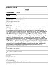
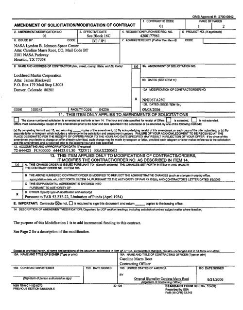
The puxpose of this Modtfication 1 is to add incremental funding to this contract.<br />
See Page 2 for a description of the modification.<br />
ExceDt as Drovlded herein all terms and conditions of the document referenced In Item 9A or lOA. as heretofore changed remains unchanged and In full force and effect.<br />
15A. NAME AND TITLE OF SIGNER (Type or print) 16A NAME AND TITLE OF CONTRACTING OFFICER (Type or print)<br />
Caroline Marrs Root<br />
Contracting Officer<br />
15B CONTRACTOR/OFFEROR 15C. DATE SIGNED 16B UNITED STATES OF AMERICA 16C. DATE SIGNED<br />
(Signature of person authonzed to sign)<br />
NSN 7540.Q1-152-8070<br />
PREVIOUS EDITION UNUSABLE<br />
BY<br />
30-105<br />
Onglnal Signed by Caroline Marrs Root 9/21/2006<br />
(Signature of Contract/na Officer)<br />
STANDARD FORM 30 (Rev. 10-83)<br />
Presc~bed by GSA<br />
FAR (46 CFR) 53.243
<strong>NNJ06TA25C</strong><br />
Modification 01<br />
Page 2 of2<br />
The purpose of this modification is to proVIde mcremental fundmg in the amount of$563,000,000; hereby increasing the allotted<br />
amount from $27,000,000 to $590,000,000. Funding recapitulation is shown below:<br />
Cost<br />
Fee<br />
Total<br />
Previous This Mod 1<br />
27,000,000 563,000,000<br />
New Total<br />
590,000,000<br />
The contract is changed in the following particulars:<br />
I. Clause B4. CONTRACT FUNDING (<strong>NASA</strong> 1852.232 81) (JUN 1990), is hereby deleted in its entirety and the revised clause B4<br />
shown below is substituted in lieu thereof:<br />
B.4 CONTRACT FUNDING (<strong>NASA</strong> 1852.232-81) (JUN 1990)<br />
a. For purposes of payment of cost, exclUSive of fee, m accordance with the Limitation of Funds clause in Section I, the total<br />
amount allotted by the Govermnent Schedule A is an estimate for the period of performance June 30, 2007.<br />
b. Schedule A contract funding summary:<br />
Schedule A<br />
TOTAL<br />
$590,000,000<br />
(End of clause)<br />
II. All other terms and conditions of the contract remain unchanged and in full force and effect.
OMB Approval #: 2700-0042<br />
1. CONTRACTIDCODE<br />
PAGe OF, PAGES<br />
AMENDMENT OF SOLICITATJONIMODIFICAnON OF CONTRACT 01 1 2<br />
2. AMENDMENTIMODIFICAl1ON NO. 3. EFFECTIVE DATE 4. REQUISITION/PURCHASE REO. NO. I 5. PROJECT NO. (If applicable)<br />
12 See Block 16C 4200202158<br />
S. ISSU~DBY CCCE BTfJPI 7. ADMlNlmRED BY (If other thIn Item 6) CODE<br />
I<br />
<strong>NASA</strong> Lyndon B. Johnson Space Center<br />
Attn: Bradley J. Niese, Mail Code BT<br />
2101 <strong>NASA</strong>Parlc\vay<br />
Houston, TIC 77058<br />
8. NAME AND ADDREilS 01' CONl'RACTOR (No., """'" c:ounty, state, and ZIp Code)<br />
Lockheed Martin Corporation<br />
Attn: James Blackwell<br />
P.O. Sox 179 Mail Stop LJ008<br />
Denver, Colotado 80201-0719<br />
~<br />
X<br />
I<br />
eA. AMENDMENT OF SOliCITATION ND.<br />
98. DATED (SEE ITEM II)<br />
lOA. MODIFICATION OF CONTRACTIORDER NO.<br />
NNJ06TA2SC<br />
lOB. DATED (SECE lTEMI~)<br />
CODE 100141 I FACILITY CODE 04236 09f08/2006<br />
11. THIS ITEM ONLY APPLIES TO AMENDMENTS OF SOLICITATIONS<br />
o The above numbenld ICIICItaIIOn IUmended ..... 1OIth In Item 14. The hour IIrId d .... p.olfteci for receipt of 0Ire" 0 ,,4IlCIendtd. 0 "nat extended.<br />
OIreIImuli aci
<strong>NNJ06TA25C</strong><br />
Modification 12<br />
Page2of2<br />
The purpose of this modification is to provide incremental funding in the amount of $4.890.389; hereby increasing the allotted amount<br />
from $590.000.000 to $594.890.389. Funding recapitulation is shown below:<br />
Previous 1 TIdsModU I NewTotaJ I<br />
Cost<br />
'o~ b-\' i-ltf'<br />
1<br />
Fee<br />
L<br />
-'<br />
Total S 590.000.000 J $ 4.890.389 I $ 594.890.389 J<br />
The contract is changed in the following particulars:<br />
I. Clause 84. CONTRACT FUNDING (<strong>NASA</strong> 1852.23281) (1UN 1990). is hereby deleted in its entirety and the reVIsed clause 84<br />
shown below is substituted in lieu thereof:<br />
8.4 CONTRACT FUNDING (<strong>NASA</strong> 1852.232·81) (JUN 1990)<br />
a. For purposes of payment of cost, exclusive of fee. in accordance with the Limitation of Funds clause in Section I. the total<br />
amount allotted by the Government Schedule A is an estimate for the period of performance October 17. 2007.<br />
b. Schedule A contract funding summary:<br />
Schedule A<br />
COST<br />
bf<br />
FEE<br />
bf<br />
(End of clause)<br />
TOTAL<br />
$594.890.389<br />
II. All other terms and conditions of the contract remain unchanged and in full force and effect.
OMB Approva IN 0.27 ()O. 0042<br />
AMENDMENTO'SO~~rrATIOW Jl CQIoITIVICIIU COllI: I PAll~ OF rAGES<br />
MODIFICATION OF coNTRACT I NNJClI'.T A "~(' I I I .!!JP<br />
~. I NO. ~ : nAT!;' • J>I' lII«':IlAllli RM NO I ~ ""'" ,cr.T NO<br />
18 N1A I N/A<br />
6 ISSUEOUV I cooe 7 AOMIN1S1~neOIlV(!I""""_'_6J (COOE I<br />
<strong>NASA</strong> I.yndon B. Johllslln Spuw Ccnter<br />
Alln: LlT/J"~~lca Corley<br />
210 I <strong>NASA</strong> PUrllWllY<br />
1I0118tOIl. TX 1705f1<br />
~PP~D<br />
LL~~<br />
It ........ • 1 OJ: 11No .. ·""" ._ ...... J&"YI1'O( [l~ENT<br />
l.ockhL'Cd Marlin Corpol
I. (a). Clause 0.3, Estimated CQst and AWard Fee, for completion form work is<br />
summarized as follows:<br />
Elemcnt From I To Changc<br />
Estimated Cost I LL I JL _<br />
bf<br />
Fee<br />
PI<br />
4/{ ~<br />
-<br />
I<br />
Total I 54.270,600,905 I $4,329,791,521 559,190,616 -<br />
NNJ06TA2SC<br />
Modification 18<br />
Page 2<br />
(b). 0.3 Estimated Cost and Award Fee is deleted in its entirity and replaced with the<br />
following:<br />
"B,3 ESTIMATED COST AND A W AID FEE tNFS 1152.216-85> (SIP 1993)<br />
•• The estimated cost and award fee for Schedule A (base foe not applicable) of this contract<br />
is broken out as follows:<br />
Completion form work<br />
(all work not identified as 101Q) btj<br />
i<br />
Estimated Mgimwn ThIll S:QJl<br />
~ Award fee and Award Fee<br />
•<br />
he-I ht(<br />
IDlQ Oelivery Orders Issued·· &q- bY 01-<br />
Total hI{ Jo'{ 1.1..J,29.1.f1.z'f.Z<br />
•• NOTE! Work subje
· .'<br />
NNJ06TA2SC<br />
Modification 18<br />
Page 3<br />
6.1.3.6 Mechanisms<br />
n <strong>NASA</strong> wID provide the CEV to ISS dOSkinC adapter for ISS dgsking.<br />
I) The Contractor shaD Integrate the elv to ISS doddD,adapter for two adapter<br />
deUvea mllslons tq ISS. DI. fgtegr.tlOD Inslpm <strong>NASA</strong> provided avionk.<br />
required to operate Andromou. Peripheral A.sembly Systems.<br />
III. Section]. Attchment J-ll entitled "Government Furnished Property List". and<br />
Attachment 1-1, "Award Fee Plan, Schedule A" are deleted in their entirety and<br />
replaced with the attachments to this modification.
ATTACHMENT J-7<br />
AWARD FEE EVALUAnON PLAN<br />
CREW EXPLORAnON VEHICLE<br />
Contract NNJ08TA25C<br />
Schedule A<br />
Ayaytt 27· ~~1 ... _<br />
. _<br />
r,;:---------.---. .<br />
,~"!!!!... .. _-- .
NNI06Tmc Auachment1-7 Ii"=..-------.'~<br />
I L:C:;:.I'O:.:.w:.;Ex=PI::;oratio=·<br />
,::.D .:.V:::eh:::ic:::Ie;....-..:;(CBV)=.:.!.-___________<br />
--.:M:::od=ifi:::cati:::·:;;;OD::.:lII~ u..~ __ . ____ , __ JJ<br />
I. INDlQpUgnON<br />
In accordanCe with thl ptOvieIonI of the Federal AIlqulaltlon AlQulatIon (FAA), and <strong>NASA</strong> and JSC poIfcfll,<br />
a performanot Muatlon proctdu" Ie hMby aatabIlehlid tor dttetmlnatlon of award .... payable under<br />
th. oontract. Tk awant fee Ie deaIgned to provide aconomIo motIYatIon tor the Conhctor 10 PfOYIdI<br />
timely, high quality outpull that .xceed the minimum raqul~ 0/ the oontract. The Inttnt 01 this plan Is<br />
10 set up jIIOClldUNI tor evaluatIOn of Contractor ptIformanoe uaInO tIdItInQ data and syatamalO the<br />
maximum IXIiInt Whlle Impoalng minimum acfmlnletratl\lt llurdtn on the CiOvemment and ContIaotor. The<br />
payment of any aW8ld tee Is oontIngent upon eompIlanot with oonlIaotuaI requlrementa and pedonnance to<br />
the degreelf*lllac:t below.<br />
This ccntraot la a hybrid oontI'aot COIlIIIBllng 01 thf81 achtclUllI, SCIIIdUlII A, B, and C. AW8Id fee<br />
Muallon lor SclledulII A and C ." covered by attachmanta J.7 and J.17, rtapecllvely. Scheclule B<br />
c:ontaIna BipIltate 1nCentI\118 SIIICHIC to that oontlacl sc:hedule. and Is not lubject to a.i'd fH ptOVIeIona.<br />
Th. Contractor'. Interkn parfonnanol under Schedule A will be evaluated by <strong>NASA</strong> at the 8lCp1ra1ion 01<br />
I80h ptriod 8p11CIlIeclIn EncIoIIn II, Performance Mlleetonll. The Mluatlon to be performed by <strong>NASA</strong><br />
wli be baud on <strong>NASA</strong>' ....... IntrII'of the COnttacIoI'elCCOl'llpl/ahment 0/ the vadoua .... of WOIIt<br />
~ by the Sw.ment Of WorJc.ln accordance with the tao\OI8, ~n"" ptOCadurI8, and other<br />
(IIOVI8IcInIi8lt foIth below.<br />
The .mount of a~e Awant Fee In _ P*Iod Is 'ubliIOt to eqult8blt id/..unenlilarillng flOll'l chengee<br />
or otheroonrict 1fIOd1llclillOnl. The 8IIIOUIit 01 the Awant 1". to be paid Is determined by the<br />
GowIrIrntnI'a evaI~ 0/ the CcInIracIoft partarmanoe In '*"" 0/ the orItarilltated In .... oontraot. Thle<br />
determination and ttMi hIeIhocIOIOgy, rot d4ItermInlnO N AWIIII Fee .,. unllaterald.olelonl mede eo/ely at<br />
tha dIscINIIoh Of the Governrntnt. The eJovemment may unll&te!allY ChanQt any a_ of this plan nOl<br />
otherwlle Nqulrlng mutual agreement under the oontract. Such ctI8ngea wll be made prior to the<br />
beginning 0/ an llVllualiOn J*Ibd to which the changet eppIy by \IIT18Iy notice to the contfaotor In writing.<br />
The COrItt8CIDr will be Informed o/any changee to the llVlluatlon criteria or the welghtfnga prior 10 the<br />
affected AWIId Fee period.<br />
Each awald '" evaluation. with the m:aptiOn of the Iaat evaluatlon, will be an IntetIm evaluallon and 11\.<br />
COI'f8IPOIIdInO tee payment 18 pnlVIllonaI only. All Interim evalua~ and provisional tee paymente will be<br />
superseded by the llna! evaluation and fee deterrnlnltlon lor SchIIdIIIe A.<br />
Attachment J·7<br />
Page2of8
IL<br />
gRQANIZADONAb tmucnJM<br />
A. '-fotnIInce I!vaIlIItIon loan! IntegrltJon T_ (PEB-IT)<br />
The pEB-rr wtU be compoaad of aeIeded <strong>NASA</strong> technical and admlnlalrative pel8Ol1llei and headed by the<br />
ContraCtIiIa OffIceI'a Technical Repraaenta1lVe (COTR). The COTR Will be the roc.! point for the<br />
accumulatIOn and devt/Opmtnt 0/ A~' F .. evaluation reporII. rlVlewe. and preaantallolw. as weft aa<br />
dlllCU88lon!l with Contractct manaoament 011 Award F .. matte". The PEB-rr Will evaluate the
11L..,;~;.;.;rew;.;.;I06...;;ix.;.;o~;;;.;lo""~=n_v",,eh;.;.;iC....;,le_-.:..(CBV)....;....:,-___________<br />
~.;...~_ifi_C_atiOlI_·<br />
The FDO Win consider thl recommendation 01 thl PEl, PEB-IT Report, Information provided by th&<br />
CClnlraotor, If any, and any other pelllnent Information In d8l1IImInlng the ptIformance ecore. The FOOl<br />
delllrminalion 01 thl IICOrI will be lilted In a wrItlIIn Award F .. Dttennlnatlon and will be plOVlded 10 1111<br />
ContIICIOf by the contracting 0II1cer within 48 calendar days attar IhI end 0I1hI evaluation plllod.<br />
-7;...;..<br />
t_l lA<br />
....<br />
....<br />
, tL~_-==== D<br />
II. IYN.lIA'I\ON PRQCIQURQ<br />
Schedule "AM DOTal<br />
<strong>NASA</strong> will evaluatIIlhiI contIMt IIChlduieln ~ with 1111 cIIuae NFS 1852,218-77, Award Fee For<br />
End "*" ContracfII. £ach award 'ee pl/lod wtU be baled on objectlw project mUeatortet IdentlfIad In !hie<br />
plan end CQ'l\r8CllIChed\lle. ElICh Inllrtm award fee period and provisIOnal payment Ie baIIId on the<br />
ConUacIDr'alucce.tul con\pI8IIon 01 the inHaatone(a) agreed 10 and aaldantifled In !he Contractor'a<br />
Integl'lllld Maatef8dMlcfull (IMa). The award fee dlstrlbultCn tIbIt contained In EncIoeure II, Performance<br />
MlIeemeI, pIOVid ... ,'" 01 p6I1omlll'lCe mUllion .. and availlblt provIalonal f .. for each mllellOne. In<br />
acconfance with NFS 1882.218-1'1. all award fie avaIuatlOnl. with lhIelllCtPllOn 011111 last evaluation. will<br />
be Inllrtm lYlluaIIonI.<br />
Ob/ICIIVII and I\I~ CrItIrIa<br />
NO later dIM 30 ca/endar daya ptIor 10 the 8tIrt of each Irrtellm Aweni P .. evaluation period (mll8lt«Mt),<br />
the Qo/ItIaCtOt may IIbnIt \0 the ContrIcIIng OffIcer rtoorMIended ~ perfolmlllCe mettlca.<br />
weIQhIIngt, and A,... 01 rtnphu/I (ACE) for CI;lI'IIIldtretion by <strong>NASA</strong> 10 be uI8d for the enau/ng evaluation<br />
period.<br />
<strong>NASA</strong> wit tttabIIeh performance rnauIoa and )OE for Hell lYaluatlan perIOd (m ___ ) and communlcatll<br />
thew \0 the ConIrtootcIt at .... 1 a cellI'Idar days ptIot to 1111 start 01 tadllYaluatton period. <strong>NASA</strong> may<br />
un ..<br />
terally changIIlhl walghlinga 0I1hI crIt8rIa from perIOd to peIfod. Howaver, coat conIIOI wli be<br />
waIgIMd at no '"' IhU\ 25 pII'CII\l<br />
Contraotor lilt EvaluatIOn and 8UbmIMIonI<br />
The Contractor Ihd fIlmllh a eaIf-evaJua1ion for Hell IYaIUIIIon perIOd. The eaIf.-Juation II1IIIt be<br />
~Ved by tht ConncIInIJ 0II1cer Holklng days prIOI' 10 !he end of the perIOd and IhaII be limited 10 no<br />
~ tIIIn 20 PIIJ". At the pEl 1I'IMIing., the ConttacIiof may (IIOvIdIa aeIf.tvaIuaIIon preMntltIon (a<br />
copy, of which IhaII be proyIded 10 the PEl) not to ellCHd 30 mlnutal.1n IIrIgIh.<br />
The CdnIIIIcIor will bt rum/lhld a copy 01 the ,PEl'. ~D', canoIUI/OnI, and fee recommandatloll. The<br />
ContracIDr wit be aI/oIIIId thl opportII'Ifty 10 allblnltfor COIIIIdatation of the FDO: (a) pIOJlO8ed evaluallona<br />
or conc!IuaiorIa or (b) 'liCIp~ 10 the evaluafione. concIueIona. or lee \'8CQIIIIII8Ind1ione 01 the PEl: and<br />
(0) lupportlnlJ reuorII for 1\ICh ~ or fII'OPOI*d evaluatlona or ccinoIUllonl. The ContraoIor'I<br />
.1iImIaaIonI m<br />
... be ~ In WIltIng I!Jd muit be IUbmItted IhrouOII the ContracIInIJ, OffIcer tel the FDO<br />
wflhIrI 5oWOll/lnlJdays fnIm !he date 01 the ~. ~ 01 the pEe fIrIdI~. If the ConIrIcIor doea<br />
not provId. ~ InfOrInaIIon 10 the CcInireotInO O/Ifcer within the time etat.d ab!Mt <strong>NASA</strong> wII<br />
oonoIucIe that the ContIactor oonoull WIth the .uaIIon and I'tCClI'IIIIIen 1COr&.<br />
In the event the FI)()"" not /I08IVed • submll8lon fnIm the Contrac\IQt, the per/omIanoe determlnatlOli<br />
wMl not be exeautad untilJlpilatlon of the &-worklng day period PlIlClIbeci abIMI for ConInIctor<br />
lJUbmilllOn. The COntraoIior 11181 ~ lIIe 5-worlclng day walIInlJ ptrIod by provldlnlJ • wrItlIIn etatement<br />
!hat no ~ wi. be IUbmIIied.<br />
Attachntent J-7<br />
Page4of8
Attachment 1-7<br />
L..:::::~==:::....;.;=:::.......:=~ ___________ Mod==ifi::::ca:;:;tio:.;:n~-.J (L ~_~ .____-:=~-D<br />
The Contractor ahaU submit to the Contracting OffIcer a Corrective ActIon Plan (CAP) lor any weakneaaea<br />
or tailing abj8c11v8 peI10lmlnce al'llllldenllflld by <strong>NASA</strong> II part 01 the evaluation. TIll CAP should<br />
lncIudl a d8lOrtptIon oIlI1e non-oonformance. determlnatlon of \h8 roof cause 011111 non-conformance.<br />
action raqull8d to correct the weakn ... and fjI'eVtnt *"1i'8nC8I, and the sohldull for compl*llon of tile<br />
action. The CAP IIhalI be auIlm/tIId to the ContractIng OffIcer within 30 calendar daY' after receipt 01 the<br />
eacIIlntIrIm peI10rmence dll8rmlnatlon lor the evaluation period. CoII'IcIIV8. ActIn \MIl be cIo8ed by<br />
__ Iram the Contrsotfng OffIcer and the com. FaQure to 8ubmlt a CAP within 1111 urnerraml<br />
stated above will reeult In 4 weakneaaln the next ev .. uatlon period.<br />
InI8rIm FI8dIII\Ck 110 the CoIl1rlOllOr<br />
During the OOUIM 0/ 4 perIodIo evaluatlqn I*fod. the PEB-IT wi! communlaate willi the evaluation monlto!I<br />
and 0Ihert II dlllnW ippIOpfIItIlIO IIOIIIIUl whether there ant any a ..... 01 the contraatoI'I perlormanoe In<br />
which eVIificant IrnpIo\ItI'IItI fa raquk'ld. TIle PSIT wi provide prompt wrllIIn notice II) till contJactor 01<br />
IWIY such 1IIgnIftcant ...... knOWn to him. and wII alIo hlghllQht oNr areu of BoYtrnll\ellt COIIC8m. For each<br />
such leIItr fIIuId. the contiIcIDt fa required io reepond In allmely 1TIIIMtr. aetIIng forth plane lor Inc:reaslng<br />
efIacIIveneas In the ...... Add! a ... d or 8lqlIeInfng why It II hOt taeelll810 do 10.<br />
TIle need for such IntIrIm I88dbII!.k wi! vary ICOOrdInIl to the oI~ IrwoIv8d, such II till I,""", of<br />
the 8VIlUItion I*fod. the COI'lbllClal'l ~ In pnwIoua perIOdt ... nature 0/ the WOIk baInG done<br />
during the period." Henoe. the ~ lain 10 Provide InIIIIm feedback to 1111 contractcr during<br />
the perliXt;Ht /lot PfICIuda 11'18 GowmnIent from coneIdIIIfng any dtIIcIfncy In the contnICID'" piI1oriMnoe<br />
In OOIII'1eotlcn with the cMIImlnstlon 01 the amount of. fee to be aWll/l$ld to the contracIor. TypIcally. the<br />
C30vernInent will prtwIde '''-to the CCI)IraoIor at M/y 3 I'IICII1II1Il durfnO the evalll4t1On perIOd. At a<br />
minimum. the ~ wi pItIvfde fMdbIok at Ihf· m/dpolnt of the evaJUItfon perIOd.<br />
IV.<br />
lJALUATJON CBlTiBlA AND WI!!CIHT!NM<br />
<strong>NASA</strong> will use the 1oI~ lubj8Clhle fIIcIors II a basis for arriving 411111 Inte~1II and final ,ward fee<br />
score:<br />
B. PnIgI .., ...... gement (20%)<br />
ThIs factor will Include an IVIIuation 0I1hI Contractor'8 perfolmlnOl In .., ...... 01 Program<br />
Management performanoe. both ~ end final. This Inciudel fdledule rnanaoement. 8ubcontraot<br />
AttachmentI-7<br />
PageS of8
~~~==~~~~~L_ ______________________<br />
~~~~~~<br />
Attachment 1·7<br />
management.1'lISflOI1IIIve88l, Innovation, life cycle coat management, and corporate commitment to<br />
capital illveslmentl and pel'llOnnei. (COrporate commitment to pellOl1nellnoludea tht quantity and<br />
quality of pet8OI'II1eI _",eel 10 the eEV Phaae 2 contracl QuantIty Includea rampoup and retention of<br />
qualified PlIIOI1I181 at adtqua1e I<br />
...... a to milt tchedule, coat and p8Ifonnance objllClivet. Quality of<br />
peI80IVIiI will be waluatad on the ContracIor's lU00M8 In maintainInG and repillOlng key ptllOlll1ei<br />
wI1hln the CEV PtIaM 2 contract.)<br />
Co COIIIllnIglIlMlflt (2ft)<br />
1'1111 faQIar wlllrioIudt an Muallon of the Contrsotor'l cost p8I'forINnce uncItr tht conttaGt. eamad<br />
Valua Manqerntnt 8yttem -. ooat performanot reporIIlI'Id other cost data sources will be uead In<br />
lilt COlt Managtmtnt IIi88Imant fOr til,. factor. COlt performance will be UI88ItCI by M1ua\lng the<br />
cost expendld on thtlClual wortc perlormld during tht perIOd btlng M1uat8d, Including quantitative<br />
..-amant of tht awaR! lie perfod cumulative COlt PIIIfoImlnoe Indtx COPl). In addition, a<br />
qualllltlll8 ......mam of app;opriate Mrneel value VlrIanctI. COlt Impllciallons or the SChedule<br />
Petformar'lce IndeX (SPI), and Other pertod"*PllDlflc cost management tnInd data will be considered.<br />
D. 8mI.~ID~luIlnlll.~Goa"(1"')<br />
The OontrICIOI'I ptIfonnance wli be lVlluatad againlt the CO/dIIICt goaJe for small/8mall<br />
dlasdvanlaald bUlln ... IUbCOntII.ctItIg.<br />
v. 'goBlNg<br />
The ptlWlliI" oJ IWt!'d _10 be pilei tot.pei'IOd Ie equat to the numerlaal80cn IIIIptd. In<br />
accoi'dlnce wIIfI the s.ctton G cIau8I for aW8ld IN, no awald fee will be paJd when ConfracIIlt<br />
perfolll1llllOl Is det8nn1ned 10 be PoorlUnlltllflCtoty.<br />
An overaY performance 8Vlluatlon and fee dlt8lmlnatfon or zenl eI1all be made for any -watlon pertod<br />
whIn there Is a mljor breach of 8Ifety or I80Urity ea dtftned In NFS 1".223-75. MIjor BIMCh of safety<br />
or Security.<br />
VI. U8T Of INCLQIUAEI<br />
EncIoIIurel: NwnerlCal Ranges and Adjectlvt Deflnillonl<br />
I!:ncIoaurw II: PIIfcJrrname Mlleatonee<br />
Modification ~"'I.!....:= .----~.]<br />
Attachment 1-7<br />
Pap6of8
AttacbmentJ·7<br />
L.,.;;;.;;.;;.;.;..;;.;.;£==;...;,.;;=~=~ ____________--,Mc.;;Od,,-=ifi;.;.;c.;.;;aao;.;.;· ""R-A.:-J ([D!!!~~_.~.~-_._-_-~-'-:I]<br />
EnClOaurel<br />
NumlflOli Ran .... II'Id AcI)eot1vt DIIInltlon.<br />
This encI08U18 sell forth the adjtCIMI ratings, dtflnl1lont, and I8IOCIattd nurntriotl rangae to be used to<br />
dellne the VlriouI IIVIII 01 ptIIotmll'a under the contJact.<br />
AOJEOTlVE RATING<br />
Excellent<br />
Very(3OOCl<br />
RANOEOF<br />
POINTS<br />
100·91<br />
90·81<br />
DESCRIPTION<br />
orelfCIPIIOnII mertt; extmplary<br />
perfolR1ll'a In • timely, effIcIent.nd<br />
economlcaI manner, vary minor (If any)<br />
d8llcltnc*i with no adveIu elf8CI on<br />
overall pt\'fOIrnaI1CI.<br />
80·71<br />
70·61<br />
iPQOriu-niiiiietacto--;y--- •--rao-.-o------neo.=-not.:=m:::c<br />
..<br />
M .... or IIId111v &XC\I8dI minimum<br />
~-ii8iicfard.l adtqua18 reeUla;<br />
rtpOIIatlIt dtftclenolal with IdtntHlablt,<br />
bill not 8Ubttlntial, efI8CIt 01'1 overall<br />
perIonnance.<br />
=mI:;::nIm=um=aoceptib/==r.:-.--<br />
IIIIIndaIdIIn one or mort a,..; remedial<br />
IlGIlon required In one ot mont ....;<br />
~ .. In~.~.~ .... whlch<br />
adVIl1HIIV affect QWqJf I<br />
.'<br />
Attacbmentl·7<br />
Pap7of8
Attachment J·7<br />
~~~~==~~==~~~ ____________________________ ~M=od~i~fi~ca=tro~n~-J ~~_13 __________ ~]<br />
Enclosure II<br />
Performance MillSton ..<br />
Performance Mlleetones will be established prior to contract award. Theae mlleetonee wYI be used u<br />
measurements of performance In accordance with Ih. Award Fee for End Item Contractl.<br />
AWARD FEE Dl8TAIBunON<br />
I .. tone EvaluatIOn PerIod I AVIUlblaF ..<br />
Schedule<br />
.--- A TP to 8131107<br />
rr.<br />
7. 911107 to 7131108<br />
rr. 811108 to 6130109<br />
f-r. 711109 to 5131/10<br />
611/10 to 2126111<br />
fs.<br />
Ie:<br />
!t\<br />
311/11 to 212Q112<br />
~<br />
$<br />
$<br />
,-<br />
S<br />
r -<br />
$<br />
S<br />
--.<br />
ElmedF ..<br />
- -<br />
I-r, 311112 to 2128113<br />
T" JIIIIJ. mZ{JllJ.l13<br />
-- ......... -<br />
S . -<br />
s<br />
---<br />
-.<br />
. -<br />
-<br />
Attachment J·7<br />
Page 8of8
NNI06TA25C<br />
I Crew Exploration Vehicle - (CEV)<br />
Attachment 1-11<br />
Modification 18<br />
ArrACHMENT J-11<br />
GOVERNMENT FURNISHED PROPERTY UST
AMENDMENT OF SOLICITATIONIMODIFICATION OF CONTRACT<br />
2.<br />
<strong>NASA</strong> Lyndon B. Johnson Space Center<br />
Attn: Bradley J. Niese, Mail Code BT<br />
2101 <strong>NASA</strong> Parkway<br />
Houston, TX 77058<br />
Lockheed Martin Corporation<br />
Attn: Bethany Lane<br />
P.O. Box 179 Mail Stop W3004<br />
Denver, Colorado 80201-0719<br />
_<br />
The above numberecllOlldtatlOn Is amended II set rortIIln Item 14. The hOur end dale Ipec:Ifted for receipt of Orrtta Is ex1ended.<br />
Oft'ara muat ackmwIedge receipt of this _ment PrIor to the hour and dale IllilCllfIlll In the a:aIIcitaUon or as amended. bY one
NNJ06TAlSC<br />
Modifieation 29<br />
Page 2 of8<br />
(I)<br />
Definitization of Contract Change Order (CCO) 17 affects Schedule A of this contract as follows:<br />
(a) Clause B.3 Estimated Cost and Award Fee (NFS 1852.216-85) (SEP 1993) for C~mpletion<br />
Form Work is increased, based on the mutually agreed to negotiated price of! b'f I as<br />
follows:<br />
Estimated Maximum Total Cost<br />
Cost Award Fee and Award Fee<br />
. - -r---<br />
~ ~<br />
Previous<br />
1<br />
1---- I--<br />
This Modification<br />
~ bl{<br />
Iff<br />
I<br />
New Total ~I<br />
$4,392;682:5331<br />
(b) Contract Schedule A, Section B, Clause B.3 entitled "ESTIMATED COST AND A WARD<br />
FEE (NFS 1852.216-85) (SEP 1993)" is revised as set forth below.<br />
"B.3 ESTIMATED COST AND AWARD FEE
<strong>NNJ06TA25C</strong><br />
Modification 29<br />
Page30fS<br />
here identifies the current authorized work. The maximum potentiallDIQ contract value is<br />
identified in Clause 1.7 ORDER LIMITATIONS.<br />
(End of clause)"<br />
(c) Contract Attachment 1-1 entitled "Statement of Work - Schedule A" is revised as set forth<br />
below. Only changes (additions, deletions and revisions) to this con~ attachment are<br />
contained herein.<br />
(i) The following is added to paragraph 0) of Section 2.3(C):<br />
1.3.(C) SPACECRAFT INTEGRATION<br />
• ISS C3l Communications Adapter (ICCA)<br />
(ii) The following paragraph (p) is added to Section 2.3(C):<br />
2.3.(C) SPACECRAFr INTEGRATION<br />
p) The Cotrttactor shall develop and maintain the ISS Resident RF equipment to ICCA<br />
Interface Control Document in accordance with ORO CEV -T -029 Interface Control<br />
Documents.<br />
(iii) The following paragraph (t) is added to Section 2.6.1 :<br />
2.6.1 AVIONICS INTEGRATION<br />
t) The Contractor shall lead the integration of the integrated resident RF communications<br />
hardware and the OFE provided ISS eJJ Communications Adapter (ICCA), with the ISS.<br />
(iv) The following paragraph (c) is added to Section 2.6.2:<br />
2.6.2 COMMAND AND DATA HANDLING (C&DH) INTEGRATION<br />
(c) The contractor shall participate with <strong>NASA</strong> in the integration ofCEV hard-line<br />
interface to the OPE ICCA onboard ISS.<br />
(v) The following replaces the first paragraphJn Section 2.6.3:<br />
2.6.3 COMMUNICATIONS AND TRACKING<br />
The Contractor shall integrate the DDT &E efforts of the space-to-ground and space-tospace<br />
communication links, RF/optical tracking devices (excluding navigational aids),<br />
and audio and video/imagery equipment, ihcluding hardware to be installed on the ISS.<br />
(vi) The following paragraphs (f), (g), and (h) are added to Section 2.6.3:<br />
2.6.3 COMMUNICATIONS AND tRACKING<br />
t) The Contractor shall design, develop. produce, integrate, verifY. validate, certifY,<br />
operate, maintain. document, and deliver ISS resident RF communications hardware<br />
(antenna, amplifiers, transponders, baseband processing. and other associated hardware).<br />
g) The Contractor shall integrate the resident RF communications hardware with the<br />
OFE proVided ISS C3I Communications Adapter (ICCA).<br />
h) The CEV Contractor shall participate with <strong>NASA</strong> and the Constellation Program in<br />
development of Radio Frequency (RF) spectrum management in compliance with the<br />
National Telecommunications and Information Administration (NTIA) Manual of<br />
Regulations & Procedures for Federal Radio Frequency Management (May 2003 Edition.<br />
May 2005 Revisions), Chapter 10. The Contractor shall provide RF spectrum<br />
management documentation in DR» CEV-T -026, Spectrum Management Docwnenls for<br />
the ISS CCA which is separate from the CEV stage 1,2 and 3 application.
<strong>NNJ06TA25C</strong><br />
ModifieatioD 29<br />
Page40fS<br />
(vii) The following paragraph (k) is added to Section 2.6.9:<br />
2.6.9 Structures Integratiou<br />
k) The ISS CCA will be hard mounted on a contractor provided isolation system for<br />
launch on Progress.<br />
(viii) The following paragraphs (h), (i) and (j) are added to Section 2.6.11:<br />
2.6.11 SuitltEVA and Survival Crew Equipment Support Systems Integration<br />
h) The ISS CCA primary assembly and the remotely located antennas will be mounted on<br />
the exterior of the ISS.<br />
i) The ISS CCA mOUDting design wi1l be passive.<br />
j) <strong>NASA</strong> provided 'brackets' will include any retention mechanism and latchinglbolting<br />
mechanism to secure the CCA to the ISS.<br />
(ix) The following paragraphs (b), (e) and (d) are added to Section 6.1.33:<br />
6.1.3.3 CM CommunieatioDS and Tracking<br />
b) The contractor shall provide the CEV to ISS CCA hardware and documentation<br />
necessary for CEV docking to ISS.<br />
c) The Contractor shall work with <strong>NASA</strong> on the integration of the CEV to ISS CCA<br />
hardware into the ISS.<br />
d) Any <strong>NASA</strong> provided components will be designed for environments consistent with<br />
ISS and Progress.<br />
(x) The following paragraph (h) is added to Section 6.1.3.6:<br />
6.1.3.6 CM Mechanisms<br />
h) The ISS CCA OSR's will be mounted such that they have a clear view to deep space.<br />
(xi) The following paragraphs (1) and (m) are added to Section 6.1.6.1:<br />
6.1.6.1 CM Fligbt Hardware AI&P<br />
1) The Contractor shall integrate, assemble, certify, acceptance test, and deliver flight<br />
hardware, for installation to the ISS meeting the requirements of CBV and the<br />
environments/requirements of ISS in accordance with the CEV to ISS IRD.<br />
m) ISS CCA qualification and acceptance testing will be conducted at the assembly level.<br />
(d) Contract Attachment J-3 entitled "Applicable, Guidance, and Informational Documents List" is<br />
revised as set forth below. Only changes (additions, deletions and revisions) to this contract<br />
attachment are contained herein.<br />
(i) All documents listed below are to be added as Applicable:<br />
I) CXP-70031 Revision A<br />
15 February 2008<br />
International Space Station (ISS) to CEV IRD<br />
(ONLY APPLICABLE FOR EFFORTS ASSOCIATED SPECIFICALLY WITH<br />
THE ISS COMMON COMMUNICATION ADAPTER)<br />
2) 1132928-103<br />
Revised 10/071200]<br />
International Space Station Program<br />
REQUIREMENTS FOR INTERNATIONAL PARTNBR CARGOES<br />
TRANSPORTED ON RUSSIAN PROGRESS AND SOYUZ VEHICLES<br />
(ONLY APPLICABLE FOR EFFORTS ASSOCIATED SPECIFICALLY WITH<br />
THE ISS COMMON COMMUNICATION ADAPTER)
<strong>NNJ06TA25C</strong><br />
Modification 29<br />
PageS ofS<br />
3) ClCP 70036A (rev A) with Errata (CEQATR)<br />
(ONLY APPLICABLE FOR EFFORTS ASSOCIATED SPECIFICALLY WITH<br />
THE S-BAND TRANSPONDERS)<br />
4) SSP-SOOOS International Space Station Flight Crew Integration Standard<br />
(ONLY APPLICABLE FOR EFFORTS ASSOCIATED SPECIFICALLY WITH<br />
THE ISS COMMON COMMUNICATION ADAPTER)<br />
(e) Contract Attachment J-7 entitled "Award Fee Evaluation Plan Crew Exploration Vehicle<br />
Contract NNJ06T A2SC Schedule A" is revised as set forth below. Only changes (additions,<br />
deletions and revisions) to this contract attachment are contained herein.<br />
Enclosarell<br />
Performaaee Milestones<br />
Performance Milestones will be established prior to contract award. These milestones will be<br />
used as measurements of performance in accordance with the Award Fee for End Item<br />
Contracts.<br />
AWARD FEE DISTRIBUTION<br />
Available<br />
EvalaatioD Available Total<br />
Fee: IDIQ<br />
Period I Milestoae Period Fee:<br />
Available<br />
Delivery<br />
Schedule Milestones<br />
Fee<br />
Orden<br />
ATPto<br />
8/31107<br />
911/07 to<br />
7/31108<br />
811108 to<br />
6/30/09 ,<br />
7/1109 to<br />
5/311\0<br />
Interim<br />
EamedFee<br />
-<br />
...... .. - ..<br />
~<br />
611110 to<br />
2128111<br />
0 'v>~ ~ \-J~<br />
,<br />
3/1111 to<br />
2/29/12<br />
311112 to<br />
2/28113<br />
~<br />
..<br />
-<br />
~-<br />
311113 to<br />
10/31113<br />
£ ............<br />
,<br />
. -
NNJ06TAl5C<br />
Modifi~atioD 29<br />
Page 6 ofS<br />
(f) Contract Attachment J-8 entitled "Subcontracting Plan for Small Business Concerns" is revised<br />
as set forth below. Only changes (additions, deletions and revisions) to this contract attachment<br />
are contained herein.<br />
Table A-ScheduJe A is deleted in its entirety<br />
. r,'<br />
". •<br />
SclfeduJe A SumnrtII'Y is revised as set forth below.<br />
Contract VRlue' S 4. 413916803<br />
Total Dollar<br />
Schedule A SUIIfIIfIUY I % Total I<br />
% Total Contract<br />
Value Subcontract DoDan Value<br />
Total SB<br />
WOSBTotal<br />
SDBTotai<br />
SDVTotai<br />
)JX<br />
b~ ~<br />
-<br />
VOSBTotai<br />
HUBZone<br />
HBCUIMI<br />
LaraeTotai<br />
-<br />
-<br />
Total Subcontracts<br />
I<br />
(g) Contract Attachment J-9 entitled "Deliverable Items List" is revised as set forth below. Only<br />
changes (additions, deletions and revisions) to this contract attachment are contained herein.<br />
(i) Add new section entitled "ISS COMMON COMMUNICATION ADAPTER (CCA)<br />
HARDWARE" after the HARDWARE section and prior to the ELECTRICAL<br />
GROUND SUPPORT EQUIPMENT (EGSE) section of the Deliverable Items list as<br />
follows:<br />
ISS COMMON COMMUNICATION ADAPTER (CCA) HARDWARE<br />
2 ea - Shipse"* of ISS CCA Emulaton **<br />
1 ea - Shipset* of ISS CCA Engineeriug Vuit**<br />
1 ea - Shlpset* orISS CCA Qualification Unit<br />
1 ea - Shipset* of ISS CCA ISIL Vult<br />
1 ea - Sbipset* of ISS CCA DSIL Unit<br />
2 ea - Ship .. "* ofISS CCA FUght Uni ..<br />
1 ea - Shlpset* of ISS CCA Flight Uuit (Spare)<br />
1 ea - ISS Unique GSE Test Cart<br />
Hardware will be delivered to <strong>NASA</strong> via 00250<br />
Scheduled DeUvery Date<br />
11912009<br />
61112009<br />
41112010<br />
1/lI2011<br />
11112012<br />
41112011<br />
41112011<br />
101312009<br />
·A shipset consists of the following: I each Baseband Processor, S-band Transponder,<br />
Diplexer, High Power Amplifier (HPA), Low Noise Amplifier (LNA), I Antenna switch<br />
assembly, 3 low gain antennas. 120 Volt to 28 Volt Power Converter, cold plate, thermal<br />
protection Blankets and connective cabling exclusive of the RF connective cable between<br />
the antennas and the end item deliverables<br />
··There is no acceptance test for the Test Units - functional checkout is completion<br />
criteria for DD2S0
<strong>NNJ06TA25C</strong><br />
Modifi~ation 29<br />
Page 7 ofs<br />
(h) Contract Attachment J-II entitled "Government Furnished Property List" is revised as set forth<br />
below. Only changes (additions, deletions and revisions) to this contract attachment are<br />
contained herein.<br />
(i) Add new item to Section 2.0 GovernmeDt Provided Property List as follows:<br />
, .<br />
,<br />
GoverDmeDt-Provided Property SOW RefereDu Due Date<br />
--<br />
~L1<br />
/3lf •<br />
. .<br />
B,/<br />
- - '"<br />
ion<br />
.....<br />
B'I . . "<br />
B'i<br />
I~ 'f"<br />
" .<br />
I- -<br />
IYf<br />
(Sf(<br />
) I /YI<br />
I<br />
I --::--<br />
I<br />
-<br />
(i) Contract Attachment J-12 entitled "List of Government Facilities" is revised as set forth below.<br />
Only changes (additions, deletions and revisions) to this contract attachment are contained<br />
herein.<br />
(i) Add new items and durations to List of Government Facilities:
<strong>NNJ06TA25C</strong><br />
Modification 29<br />
Page 8 of8<br />
1<br />
(<br />
)<br />
0) In consideration of the modification agreed to herein as complete equitable adjustment for all<br />
claims arising out of or attributable to the issuancc of the contract changes andlor contractor<br />
proposals listed below, the contractor hereby releases the Government from any liability under<br />
this contract for further equitable adjustment attributable to such facts or circumstanccs giving<br />
rise to said contract changes andlor contractor proposals, and for such additional obligations as<br />
may be required by this modification.<br />
Contract Change:<br />
Contractor Proposal:<br />
Contract Change Order 17, dated August 14, 2007, and all<br />
updates provided thereto<br />
Firm proposal NS0029, dated November 8, 2007, and all updates<br />
provided thereto<br />
(2) Contract Attachment J-16, "Integrated Project Schedule" is revised to update Table J-16-1, ''CEV<br />
Project Schedule A Milestones" PA-I Test Flight Launch Date from 9/23/08 to 12111108.<br />
(3) All other terms and conditions of the contract remain unchanged and in full force and effect.
OMB Approval.: 2700-0042<br />
1. CONTRACT 10 CODE<br />
PAGE OF rGES<br />
AMENDMENT OF SOLICITATION/MODIFICATION OF CONTRACT NNJ06TA2SC I 1 7<br />
2. AMENDMeNTIMODIFICATION NO. 3. EFFECTIVE DATE 4. REQUISITIONIPURCHASE REQ NO. J 5. PROJECT NO. (II app/IceIII&)<br />
65 MAY 282009 N/A N/A<br />
8. ISSUED BY CODE 7. ADMINISTERED B "t.mdJ<br />
BT 1 JPI CODE l<br />
<strong>NASA</strong> Lyndon B. Johnson Space Center<br />
~:PROVED<br />
.~...<br />
Attn: Bradley 1. Niese, Mail Code BT<br />
-'1"'1.......r.<br />
2101 <strong>NASA</strong> Parkway JSC P~Q~UREMENT<br />
Houston, TX 77058<br />
~:J..0FFICER<br />
$: L.:2 I".<br />
8. NAME AND ADDRESS OF CONTRACTOR (NO.. lInN( county. SII,., anti z;, Code)<br />
.J&. IIA.<br />
Ll 'AlE<br />
Lockheed Martin Corporation 9B. DATED (SEE ITEM 11)<br />
Attn: Linda Dozier<br />
2625 Bay Area Blvd lOA. MODIF1CATION OF CONTRACTIORDER NO.<br />
Houston, TX 77058<br />
<strong>NNJ06TA25C</strong><br />
X<br />
108. DATED (SECE ITEM1IfC)<br />
CODE 100141 I FACIUTY CODE 04236 09/0812006<br />
11. THIS ITEM ONLY APPLIES TO AMENDMENTS OF SOLICITATIONS<br />
g. The aboVe numtitnId IOI/CItatIoIIIt amended II aet forIh In IfIIm 1.. The hour lind CIIIt 8p1C1t!ed.1or ~ or ~ _ g _ It extended, g _<br />
Is nat.xtllnded.<br />
Oft'eq must of this ameolClment to the hour and dalupecHlId In tllualldtatlOn or. _ . one of the meIIIads!<br />
(a) By campIeIfng HernIa and IS. and leIIIm~ aapIea of the amend(ntnt; (b) By acIcnawI8dglng raceIpt 01 tIIlt ~nt an tIICh 0IJf1I or the affer aubmltllld; CIt (e) 8y<br />
aepetate IeIIet or_,.,.. WIII\:h In\lIllC'." to thIi IOIIc/t.IIon and arI1enCIrnirit numbels. FAIWRE OF YOUR ACKNOWLEDGMENT TO BE RECEIVED AT THE<br />
PlACE oeSIGNATEO FOR THE RECEIPT OF OFFERS PRIOR TO THE HOUR AND DATE SPECIFIED MAY RESULT IN REJECTION OF YOUR OFFER. If by virtue or this<br />
amandment ycu deIIre to cIIanoe an aItet alreedy eubmltlld. eucII cllange may be mede by"""", or letter, plOvfded aacII telegram CIt IeIIar __..-.-to the<br />
.. nent. and Is ~ p!Ior to the opening hour and dale !l!IC!fted.<br />
8CII!c!!atIon lind this _<br />
12. ACCOUNTlNGANDAPPROPRIATION DATA (lIf8qU/18d)<br />
N/A<br />
13. THIS ITEM APPLIES ONLY TO MOOIFICAnONS OF CONTRACTS/ORDERS,<br />
IN<br />
&. IMPORT,\NT: Contractor Olano!, ~ " required to sign !hili doc:urnent and retum.....J..... copies to the issuing oIfIce.<br />
14. DESCRIPTION OF AMeNDMENTiMODlFlCATION ~ by UCF HCtIott heetItntA IIrr:Iudlng ecIIt:ItiIfIonI subJ«;t /IIIIIfeI' w/Ier8 fHsIbIe.)<br />
The purpose of this modification is to defmitize Contract Change Order (CCO) 24, dated November 30, 2007.<br />
For a detailed description of the changes, see pages 2 -1.
<strong>NNJ06TA25C</strong><br />
Modification 65<br />
Definitization of Contract Change Order (CCO) 24 affects Schedule A of this contract as<br />
follows:<br />
Page 2 of7<br />
(1) Based on the mutuaOy agreed upon negotiated price of 51,901,000,000 for this action,<br />
contraet value for Schedule A Completion Form Work is equitably adjusted as follows:<br />
Previous<br />
li'dimsat"d Cnd I Award Fee I Total I<br />
This Modification<br />
b.t. ~'k bl-f<br />
New Total I I $6,293,682,5331<br />
(2) Contract Schedule A, Section B, Clause 8.3 entitled "ESTIMATED COST AND<br />
A WARD FEE (NFS 1852.216-85) (SEP 1993)" is revised as set forth below:<br />
"8.3 ESTIMATED COST AND A WARD FEE tNFS 1852.216-85) (SEP 1993)<br />
The estimated cost and award fee for Schedule A (base foe not applicable) of this contract is<br />
broken out as follows:<br />
Completion Form Work'"<br />
IDIQ Delivery Orders"<br />
-<br />
Delivery Estimate Maximum Total Cost<br />
Order Number Cost Award Fee and Award Fee<br />
-----<br />
Not Applicable<br />
$6,293,682,533<br />
-I-<br />
-I-<br />
NNJ07TA26T<br />
-I-<br />
NNJ07TA27T<br />
-I-<br />
NNJ07TA28T<br />
-I-<br />
NNJ07fA29T<br />
~~<br />
NNJ07TA30T<br />
:--<br />
NNJ07TA3IT<br />
--<br />
I<br />
NNJ07TA32T 'o~ --<br />
NNJ07TA33T<br />
--<br />
I<br />
NNJ07TA34T<br />
--<br />
NNJ07TA35T<br />
I<br />
--<br />
NNJ08TA15T<br />
-I-<br />
'tJt<br />
--<br />
NNJ08TA16T<br />
-I-<br />
NNJ08TA17T<br />
--<br />
NNJ08TA18T<br />
I<br />
-I-<br />
NNJ08TA19T :.. I-<br />
NNJ08TA20T<br />
I<br />
-I-<br />
NNJ08TA21T :<br />
-I-<br />
NNJ09TAOlT<br />
,<br />
-f--<br />
NNJ09TA02T ... a._ .......<br />
.-.<br />
loll{<br />
--
NN.J06TA25C<br />
Modification 65<br />
Pagc40f7<br />
(b)<br />
(c) (1) Base fee, if applicable, will be paid in quarterly lI1stallments based on the percent of<br />
completion of the work as determined by the Contracting Officer.<br />
(2)<br />
(3)
NN.T06TA25C<br />
Modification 65<br />
PageS of7<br />
(4) All interim (mld provisional, ifapplieablc) fcc payments wIll be superseded by the fee<br />
determination made in tho final award fee evaluation. The Government will then pay the<br />
Contractor, or the Contractor will refund to the Government the difference between the final<br />
award fee determination and the cumulative interim (and provisional, if applicable) fee<br />
payments. lfthe final award fee evaluation is "poor/ullsatIsfactory", any base fee paid will bc<br />
refunded to the Government.<br />
(5) Payment of base fee, if applicable, will be made based on submIssion of an invoice by<br />
the Contractor. Payment of award fee will be made by <strong>NASA</strong> Accounts Payable based on an<br />
issuance of a unilateral modification by the Contracting Otlicer.<br />
(d) Award fcc determinations are unilateral decisions made solely at the discretion of the<br />
Government.<br />
(End of clause)"<br />
(5) Contract Schedule A, Clause G.11 entitled "LIST OF INSTALLATION·<br />
ACCOUNTABLE PROPERTY AND SERVICES (NI
NN.J06T A25C<br />
Modification 65<br />
Page 6 of7<br />
(7) Contract Schedule A, Scction n, Clause H.28 cntitled "ORION REQUIREMENTS<br />
TAILORING" il; added to the contract as follows:<br />
"H.2S ORION REQUIREMENTS TAILORIN(;<br />
(End of Clause)"<br />
(8) The folJowin/! contract J-Attachmcnts are delcted in thcir entircty and replaced with<br />
the updated attal!hments included with this modification:<br />
Title<br />
Stat-em-cnt of W(;rk - ._-<br />
--------<br />
- .. ._._--'--- - -----<br />
Data Procurement Document (DPJ») &<br />
DRD Submission Matrix<br />
---<br />
Applicable, Guidance and Inlormation<br />
Documents List<br />
------~.~~ ...... --- .-<br />
~~. _._ . Gloss~~ ______ _<br />
J-7 Award Fee Plan<br />
... J-8 _.___ Subc~£ting Plan fo~_Small Rusi_!.lE~~<br />
-- ------ - - ------.--~--<br />
J-9 Deliverables Items List<br />
J- t 0 List of Installation Accountable Property<br />
.---...~<br />
1nd Services<br />
-.'- .. --.-~-..-~. ---.<br />
Qovernmef!.~ Furnished Pr~2£rt.l. (GF~) __ .<br />
Government Facilities<br />
l-----''---- --- ---•. - ._-<br />
L....-._J_-_16_ .•..• _ [ntegrated J)!()ject Sc~c::2:.u,,-le,--__<br />
(9) The following new .J-Attachmcnt is hereby addcd to thc contract and included as an<br />
attachment to this moditication:
NNJ06T A25C Page 7 of 7<br />
Modification 65<br />
Attachment Title<br />
J-26 Orion Tailored Re uirements List<br />
(10) Contract Schedule A, Table of Contents, is hereby updated to incorporate the addition<br />
of Section H, Clause H.28 entitled "ORION REQmREMENTS TAILORING."<br />
(11) Contractor Release Statement<br />
In consideration ofthe modification agreed to herein as complete equitable adjustment for all<br />
claims arising out of or attributable to the issuance of the contract changes and/or contractor<br />
proposals listed below, the contractor hereby releases the Government from any liability under<br />
this contract for further equitable adjustment attributable to such facts or circumstances giving<br />
rise to said contract changes and/or contractor proposals, and for such additional obligations as<br />
may be required by this modification.<br />
Contract Change:<br />
Contract Change Order 24, dated November 30, 2007, and all<br />
updates provided thereto<br />
Contractor Proposal: Proposal NS0034, dated November 14, 2008, and all updates provided<br />
thereto
<strong>NNJ06TA25C</strong><br />
Crew Exploration Vehicle - (CEV)<br />
Attachment J-1<br />
Modification 65<br />
ATTACHMENT J-1<br />
STATEMENT OF WORK<br />
May 2009<br />
Page 1 of119
<strong>NNJ06TA25C</strong><br />
Crew Exploration Vehicle - (CEV)<br />
Attachment J-1<br />
Modification 65<br />
INTRODUCTION<br />
The Crew Exploration Vehicle (CEV) IS the spacecraft that <strong>NASA</strong> plans to use to send human and<br />
cargo items into space and to return them to earth The CEV is an element of the overall<br />
Constellation Program that Includes launch vehicles, spacecraft, and ground systems needed to<br />
embark on a robust space exploration program This space exploration program will advance the<br />
Nation's scientifiC, security, and economic Interests.<br />
Scope<br />
The Contractor shall develop and certify the CEV System to meet the International Space Station<br />
(ISS) mission requirements. The Contractor shall develop and deliver a lunar block change plan<br />
that shows extensibility of the CEV System design to meet lunar sortie and lunar outpost mission<br />
requirements The lunar block change plan Will Identify those system deSign Items that have a<br />
development deferral to a future contract action. DUring lunar miSSions, the CEV IS used to carry<br />
the crew to low earth orbit (LEO) for rendezvous with other elements for the lunar missions and<br />
also serve as the return-to-earth vehicle for the crew. The Contractor will modify and certify the<br />
ISS CEV design as required to support lunar mission reqUirements The Contractor shall deliver<br />
the CEV spacecraft configurations below per requirements In the CXP-72000, System<br />
Requirements for the Crew Exploration Vehicle Element (CEV SRD)<br />
The following more clearly defines the different configuration variants of the CEV Spacecraft:<br />
1. Block 1A is a crewed, pressurized cargo vehicle for Low Earth Orbit (LEO) (including ISS crew<br />
change out) missions. This configuration includes.<br />
• A habitable Crew Module (CM)<br />
• A Service Module (SM) which also Includes the Spacecraft Adapter (SA) which Interfaces<br />
with the Crew Launch Vehicle (CLV)<br />
• A Launch Abort System (LAS) to provide a method for crew abort<br />
2Block 2 is a crewed, pressurized cargo vehicle for lunar missions It uses a habitable CM, LAS,<br />
SM, and SA to support lunar missions.<br />
CxP-70072-ANX 01, Constellation Systems Management Systems Plan, Annex 01. Common<br />
Glossary and Acronyms provides a detailed listing of terms used in this Statement of Work.<br />
CEV Implementation Strategy<br />
The CEV Implementation strategy reqUIres a detailed Implementation schedule to deSign the<br />
spacecraft, and implement, certify, and deliver It. <strong>NASA</strong> will work closely with the Contractor to<br />
develop the details of an Implementation strategy that maintainS the highest standards for safety,<br />
reliability, and mission assurance. Ways that <strong>NASA</strong> will work closely with the Contractor include<br />
the following. <strong>NASA</strong> will participate in daily management and deSign meetings and deCISions,<br />
<strong>NASA</strong> will work with the Contractor on the shop floor dUring development, <strong>NASA</strong> Will partiCipate In<br />
the Contractor Material Review Board (MRB) process, as described In CXP 70059-SR&QA<br />
ReqUirements, In order to help prevent stop-work conditions, and <strong>NASA</strong> will work with the<br />
Contractor In the test faCilities dUring integration and test activIties. The purpose of the level of<br />
participation IS for access to <strong>NASA</strong> for timely deciSions.<br />
<strong>NASA</strong> Will proVide the detailed oversight of all spacecraft deSign activities. However, the<br />
Contractor will retain responsibility for delivery of a design that meets the requirements The<br />
detailed process discussion to accomplish this can be found in CxP-72008, Crew Exploration<br />
Vehicle Project Plan. Some areas of spacecraft design will be provided by <strong>NASA</strong> and <strong>NASA</strong> will<br />
perform independent activities for requirements validation and design certification in other areas.<br />
In these areas <strong>NASA</strong> will establish design requirements teams to integrate the activities of <strong>NASA</strong><br />
Page20f119
<strong>NNJ06TA25C</strong><br />
Crew Exploration Vehicle - (CEV)<br />
Attachment J-1<br />
Modification 65<br />
and the Contractor The Contractor will participate in and support these design requirements<br />
teams. <strong>NASA</strong> has responsibility for all GFE provided equipment.<br />
The Contractor will deliver a design that ensures simplicity, minimizes life cycle cost and<br />
addresses all aspects of human spacecraft development, production, certification and operations<br />
The Contractor will design, develop, certify, and deliver the hardware required to achieve ISS<br />
miSSion requirements In Schedule A. The Contractor shall develop a lunar block change plan that<br />
shows extensibility of the CEV System design to meet lunar sortie and lunar outpost mission<br />
requirements. The lunar block change plan will identify those system design items that have a<br />
development deferral to a future contract action The concept is to develop a "common" design<br />
for the spacecraft variants, where the vehicle can be utilized for both Lunar and ISS<br />
requirements. The common design and life cycle approaches will lead to an effective<br />
implementation of subsystem and spacecraft deliveries.<br />
The Contractor is expected to develop and verify ISS mission software during Schedule A, With<br />
lunar mission software being developed In future contract action With other lunar block upgrades<br />
However, lunar mission software requirements must be evaluated to ensure the command and<br />
data handling hardware can accommodate the additional software required for lunar missions, as<br />
well as other mission objectives The "common" vehicle design shall be configured to<br />
accommodate integrating the future lunar block upgrades to achieve the lunar mission objectives<br />
while remaining Within the vehicle requirements contstraints.<br />
<strong>NASA</strong> will perform the CEV ground, flight, and training operations; design and develop CEV<br />
ground operations facilities, faCIlity systems, and <strong>NASA</strong>-provided ground support equipment<br />
(GSE); and prOVide high-fidelity simulators and trainers. Further, <strong>NASA</strong> Will conduct flight testing<br />
to demonstrate vehicle performance characteristics <strong>NASA</strong> will lead a JOint <strong>NASA</strong> and Contractor<br />
Combined Test Team (CTT) that consists of representatives from all partiCipating test<br />
organizations. In support of the <strong>NASA</strong> operations, risk reduction flight testing, and safety and<br />
mission assurance activities, the Contractor must provide the necessary data products and<br />
expertise as detailed in the SOW.<br />
<strong>NASA</strong> Will use the technical Data Requirements Documents (DRDs) to sustain and operate the<br />
CEV over the life of the Project It IS <strong>NASA</strong>'s intent to use the technical DRDs to document the<br />
CEV requirements, design, and certification activities<br />
Contract Structure<br />
To help differentiate the type of activities that comprise the Phase 2 contract, <strong>NASA</strong> has<br />
developed multiple "schedules." These include:<br />
1 Schedule A (DDT&E). This includes all design, development, test and evaluation activities to<br />
certify variants 1 A and 1 B as well as the production activities for the first actual flight module of<br />
the 1A variant, along With other deliverables deSCribed In thiS SOW. Schedule A Incorporates<br />
completion form and Indefinite delivery, indefinite quantity (IDIO) paragraphs All paragraphs are<br />
completion form unless speCifically marked as "IDIO."<br />
2 Schedule B (Production). This Includes production of all block variants<br />
3 Schedule C (Sustaining Engineering) This includes any new DDT&E effort required beyond<br />
the scope of Schedule A, such as the Block 2 variant<br />
This statement of work applies to Schedule A only. DeSCriptions of other contract schedules are<br />
provided for reference only.<br />
Page 3 of 119
<strong>NNJ06TA25C</strong><br />
Crew Exploration Vehicle - (CEV)<br />
Attachment J-1<br />
Modification 65<br />
f<br />
PROJECTMANAGEMENT<br />
The Contractor shall develop, implement and maintain a set of common project management<br />
processes, systems and data deliverables to be utilized for all contract schedules (A, B and C)<br />
throughout the life of the contract.<br />
1.1 Project Management and Administration<br />
An anchoring capability of the Constellation Program is a human-rated CEV that will carry human<br />
crews from Earth into space and back again Coupled with transfer stages, landing vehicles, and<br />
surface exploration systems, the CEV will serve as an essential component of the architecture<br />
that supports human voyages to ISS, the Moon, and beyond.<br />
a) The Contractor shall design, develop, certify, and deliver the hardware and software reqUired<br />
to achieve the LEO and ISS mission requirements The Contractor shall develop a lunar<br />
block change plan that shows extensibility of the CEV System design to meet lunar sortie and<br />
lunar outpost mission requirements The lunar block change plan will Identify those system<br />
design items that have a development deferral to a future contract action.<br />
b) The Contractor should minimize life cycle cost In the design, development, certification, and<br />
delivery of the hardware and software required to achieve the LEO and ISS mission<br />
reqUIrements In accordance With paragraph 1.1 a<br />
c) The Contractor shall ensure crew/ground safety while meeting system performance<br />
requirements and achieving mission objectives<br />
d) The Contractor shall design the CEV System to accommodate all the design reference<br />
missions defined in CXP-70007, Constellation Design Reference Missions (DRM)<br />
e) The Contractor shall design the CEV System to the requirements and terms speCified In<br />
CXP-72000, System Requirements for the Crew Exploration Vehicle Element (CEV SRD).<br />
f) The Contractor shall implement designs for the CEV spacecraft and ground systems to<br />
achieve efficient and effective operations<br />
g) The Contractor shall perform to the negotiated cost, schedule, and technical baseline.<br />
h) Reserved<br />
I) The Contractor should maximize the use of eXisting technology in the design of the CEV,<br />
unless new technology is reqUired to meet <strong>NASA</strong> requirements.<br />
j) The Contractor shall base the vehicle design on an open system architecture<br />
k) The Contractor should qualify components, subsystems, modules, and systems by test, to<br />
the maximum extent possible.<br />
I) The Contractor shall provide a CEV System that shall have a lifecycle that ends no less than<br />
20 years after the first human flight<br />
M) Contractor shall develop and document a lunar block change plan that shows extenSibility of<br />
the CEV System design to meet lunar sortie and lunar outpost mission requirements in<br />
accordance with ORO CEV-M-006 Lunar Block Upgrade Plan. The plan will identify those<br />
system design Items that have a development deferral to a future contract action The Lunar<br />
Block Upgrade plans hall be presented at each major design review. The Lunar Block<br />
Upgrade activities to be conducted In a future contract action include.<br />
• Lunar Software (Non C 3 1)<br />
• Lunar C 3 1 Software<br />
• LSAM Power Transfer Unit<br />
• Phase Change Matenal<br />
• M-5 Parachute Matenal Change<br />
• Ultra Thin Solar Array Cells<br />
• Structures Optimization<br />
• Avionics Technology Insertion<br />
• Lithium Polymer Battenes<br />
• Lunar Navigation Targets<br />
• Harnessing<br />
Page 4 of 119
<strong>NNJ06TA25C</strong><br />
Crew Exploration Vehicle - (CEV)<br />
Attachment J-1<br />
Modification 65<br />
Deliverables<br />
The Contractor shall deliver and maintain the following document(s).<br />
• ORO CEV-M-006. Lunar Block Upgrade Plan<br />
1.1.a Project Management, Systems, Planning and Reporting<br />
a) The Contractor shall implement an organizational structure for the management,<br />
coordination, and control of contract activities including the project's cost, schedule,<br />
performance, risks, contracts, and subcontracts uSing as gUidance ISO 14300-1, Space<br />
Systems - Program Management - Part 1: Structuring of a Program The Contractor shall<br />
develop and implement a project management plan that covers all aspects of project<br />
management for the CEV Project in accordance with ORO CEV-M-001, CEV Prime Project<br />
Management Plan. The contractor shall incorporate the proposed Streamlining Plan in ORO<br />
CEV-M-001, Prime Project Management Plan<br />
Deliverables<br />
The Contractor shall deliver and maintain the following document(s)'<br />
• ORO CEV-M-001 : CEV Prime Project Management Plan<br />
1.1.b Performance Management Reviews and Performance<br />
Metrics<br />
a) The Contractor shall conduct quarterly Performance Management Reviews (PMRs) with the<br />
Crew Exploration Vehicle Project Office (CEVPO) In accordance with ORO CEV-M-002,<br />
Performance Assessment Plan, Reports and Management Reviews The reviews shall<br />
provide insight Into the Contractor's, subcontractors', and vendors' overall technical,<br />
schedule, and cost performance and status<br />
b) The Contractor shall define the metrics, to be approved by government, in accordance with<br />
the ORO CEV-M-002, Performance Assessment Plan, Reports and Management Reviews.<br />
The Contractor shall update the metrics and performance data monthly and make it available<br />
for <strong>NASA</strong> review In the Contractor's collaborative enVIronment and during working-level<br />
discussions. The Contractor shall present the metrics and performance data at the PMRs.<br />
c) The Contractor shall recommend the technical performance parameters, to be approved by<br />
<strong>NASA</strong>, In the Performance Assessment Plan. The Contractor shall status the technical<br />
performance parameters quarterly in their Performance Assessment Reports<br />
d) The Contractor shall report on each SOW and SRO "should" statement at the PMR until the<br />
"shoulds" are satisfactorily accomplished.<br />
Deliverables<br />
The Contractor shall deliver and maintain the following document(s)'<br />
• ORO CEV-M-002 Performance Assessment Plan, Reports and Management Reviews<br />
1.1.c External Relationships<br />
1.1.c.1<br />
Associate Contractors<br />
a) When the working environment requires Interaction with other <strong>NASA</strong> contractors, the<br />
Contractor shall establish cooperative relationships with other <strong>NASA</strong> contractors, defined as<br />
associate contractor relationships Associate relationships are required for expeditious<br />
exchange of management and technical data among <strong>NASA</strong> contractors<br />
Page 5 of 119
<strong>NNJ06TA25C</strong><br />
Crew Exploration Vehicle - (CEV)<br />
Attachment J-1<br />
Modification 65<br />
1.1.c.2<br />
<strong>NASA</strong> Centers<br />
a} The Contractor shall establish cooperative relationships at the <strong>NASA</strong> centers to provide<br />
support (e g technical analyses, data, etc.) or understand <strong>NASA</strong> GFE and associated data<br />
deliverables (reference SOW paragraph 6.b), schedules, interfaces, and Interactions. The<br />
contractor shall work JOintly with <strong>NASA</strong> to establish contractor/<strong>NASA</strong> GFE integration teams.<br />
These relationships shall be documented in accordance with ORO CEV-M-001, CEV Prime<br />
Project Management Plan.<br />
b} The Contractor shall provide resident office space, Including phone, computer, and desk<br />
space, to accommodate <strong>NASA</strong> program office personnel.<br />
Deliverables<br />
The Contractor shall deliver and maintain the following document(s}'<br />
• DRD CEV-M-001 : CEV Prime Project Management Plan<br />
1.1.d Internal/External Project Review Support<br />
a} The Contractor shall develop briefing materials and analyses for CEV System meetings with<br />
various internal and external review groups Examples of these Internal and external groups<br />
include the flight technique panels, Aerospace Safety Advisory Panel (ASAP), Inspector<br />
General/Government Accountability Office (IG/GAO), and cost assessments teams.<br />
b} The Contractor shall prepare and present various topics, such as CEV Project technical, cost,<br />
and schedule status, speCifiC safety or risk Issues, design and development Issues, and<br />
responses to external inquiries, as directed by <strong>NASA</strong><br />
1.1.e Security Management<br />
Security management includes management of information technology security, physical/facility<br />
security, personnel security, flight vehicle security and flight test article security.<br />
a} The contractor shall use the following standards and requirements documents for developing<br />
and executing all security management processes and products'<br />
CxP 70070-ANX05-01, CxP Program Management Plan Annex 5' Security Management Plan,<br />
Book 1 Information Technology Functional Security Requirements<br />
CxP 72008, CEV Project Plan, section 4.10 and associated children<br />
<strong>NASA</strong> will be responsible for encryption handling key management, storage, COMSEC custodial<br />
activities, and operational integration at KSC, CAlL and Plumbrook<br />
b} The following documents are prOVided for Informational purposes for the contractor to support<br />
development of all security management processes and products.<br />
CxP 70070-ANX05-Book2, Constellation Program Management Plan Annex 5. Security<br />
Management Plan, Book 2. Information Technology (IT) Security Architecture<br />
Page60f119
<strong>NNJ06TA25C</strong><br />
Crew Exploration Vehicle - (CEV)<br />
Attachment J-1<br />
Modification 65<br />
1.2 Business Management<br />
1.2. (a) Financial Management<br />
Financial Management provides summary-level cost reporting by fund source, Work Breakdown<br />
Structure (WBS), elements of cost and workforce Including labor equivalent personnel (EP),<br />
overhead, and other direct and indirect costs.<br />
1) The Contractor shall develop, deliver, and implement monthly financial management<br />
reporting in accordance with ORO CEV-B-001, Financial Management Report (<strong>NASA</strong> Form<br />
533)<br />
2) The Contractor shall provide project-wide data once a year to be used In <strong>NASA</strong>'s budget<br />
planning process (e.g., program operating plan (POP) budget calls) The Contractor shall<br />
provide an annual Operating Plan (OP) update to that data for the upcoming fiscal year as<br />
requested by <strong>NASA</strong>. <strong>NASA</strong> will specify the format and content of the Contractor's inputs and<br />
rationale.<br />
3) Upon request by <strong>NASA</strong>, the Contractor shall provide project-wide budget data a maximum of<br />
three times per year. This data will be used for the purposes of gathering budget impacts for<br />
various re-plannlng scenarios <strong>NASA</strong> will specify the format and content of the Contractor's<br />
inputs and rationale.<br />
4) The Contractor shall provide property financial reports in accordance with ORO CEV-B-004,<br />
Property Financial Reporting<br />
5) The Contractor shall provide Rough Order of Magnitude (ROM) estimates as requested to<br />
support the <strong>NASA</strong> decision making process. ROM estimates shall be delivered to <strong>NASA</strong><br />
within 7 days of the formal request unless the contractor notifies <strong>NASA</strong> within 2 days of<br />
request receipt that the ROM will requires more time due to effort reqUired to bound the<br />
scope, additional reviews required, or significant complexity. The contractor shall use best<br />
available estimating techniques given the groundrules and assumptions provided by <strong>NASA</strong>.<br />
Prior to delivery to <strong>NASA</strong>, ROM estimates will be reviewed by the contractor technical<br />
community<br />
Deliverables<br />
The Contractor shall deliver and maintain the follOWing document(s)<br />
• ORO CEV-B-001. Financial Management Report (533)<br />
• ORO CEV-B-004. Property Financial Reporting<br />
1.2.(b)<br />
Workforce Reporting<br />
Workforce Reporting provides workforce Information by geographic location<br />
1) The Contractor shall develop, deliver and implement workforce data in accordance with ORO<br />
CEV-B-002, Workforce Reporting<br />
Deliverables<br />
The Contractor shall deliver and maintain the following document(s).<br />
• ORO CEV-B-002' Workforce Reporting<br />
1.2. (c) Integrated Baseline Review (IBR)<br />
1) The Contractor shall perform an Integrated Baseline Review (lBR) with <strong>NASA</strong> to establish the<br />
contract baseline Subsequent baseline reviews Will be reqUired by <strong>NASA</strong> to update the<br />
performance measurement baseline when the contract has a significant restructure or<br />
change in cost phasing. The IBR shall include the following accomplishment criteria and<br />
subsequent baseline reviews should identify only changes.<br />
Page 7 of 119
<strong>NNJ06TA25C</strong><br />
Crew Exploration Vehicle - (CEV)<br />
Attachment J-1<br />
Modification 65<br />
o Project organization fully established with cost control accounts and<br />
organization members Identified, Including interfaces and interactions with<br />
<strong>NASA</strong>. Organization and teaming roles and responsibilities defined.<br />
o Organizational staffing plans in place<br />
o IMS review<br />
o Risk management system and process review<br />
o Metrics baselined<br />
o Earned value management system and process review<br />
2) The Contractor shall ensure the technical contents of work packages and control accounts<br />
are consistent With the scope of work defined in the W8S, SOW and SRO.<br />
3) The Contractor shall work jointly with <strong>NASA</strong> to develop and document an integrated<br />
performance measurement baseline This baseline consists of all contract work Including the<br />
integration of GFE<br />
4) <strong>NASA</strong> will proVide agreed-to specific GFE performance measurement baseline data.<br />
5) The Contractor shall proVide a logical, resource-loaded, integratedflnterdependent sequence<br />
(Le. predecessor/successor network) of tasks supporting the contract schedule.<br />
6) The Contractor shall demonstrate to <strong>NASA</strong> that metnc collection methods are in place to<br />
mOnitor agreed-to requirements of the contract.<br />
1.2.(d)<br />
Cost Performance Report<br />
The Cost Performance Report (CPR) will be used to provide information for' (1) Integrating cost<br />
and schedule performance data with technical performance measures, (2) assessing the<br />
magnitude and impact of actual and potential problem areas causing Significant cost and<br />
schedule variances, and (3) providing valid, timely status Information to the CEV Project.<br />
1) The Contractor shall establish, maintain, and use In the performance of this contract, an<br />
integrated earned value management system In accordance with ANSI/EIA-748-98, Earned<br />
Value Management Systems<br />
2) The Contractor Will perform earned value analysis and shall capture, maintain, and provide<br />
<strong>NASA</strong> access to the earned value analYSIS data The earned value analysis data, at both the<br />
cost account and overall proJect-level, shall be presented as part of the quarterly PMR.<br />
Reference ORO CEV-M-002, Performance Assessment Plan, Reports and Management<br />
Reviews In addition, the contractor shall proVide electronic access to the Contractor's<br />
weekly earned value data<br />
3) The Contractor shall develop, deliver and implement CPR data In accordance with ORO<br />
CEV-B-003, Cost Performance Report, and shall support informal working-level discussions<br />
on the content<br />
Deliverables<br />
The Contractor shall deliver and maintain the follOWing document(s).<br />
• ORO CEV-8-003' Cost Performance Report<br />
1.2.(e)<br />
Life Cycle Cost Management<br />
1) The Contractor shall capture, maintain, and prOVide access to life cycle cost analYSIS data in<br />
the <strong>NASA</strong> ICE as it evolves through the project life cycle Life cycle cost definitions to be<br />
used In the analYSIS are defined In Attachment J-5, AppendiX 1, Life Cycle Cost Analysis<br />
Life cycle cost analysis data for OOT&E and operability shall be generated and presented at<br />
each major deSign review (e.g. SOR, POR, CDR) and at each quarterly PMR. These<br />
presentations shall include the latest LCC estimate, as well as a detailed diSCUSSion of the<br />
Impact from the current design, design and operations changes since the last review, and the<br />
rationale for the changes. In addition, the contractor shall utilize an integrated management<br />
assessment tool to perform affordability analYSIS to support life cycle cost management<br />
Reference SOW paragraph 2.4 Integrated Analysis<br />
Page 8 of 119
<strong>NNJ06TA25C</strong><br />
Crew Exploration Vehicle - (CEV)<br />
Attachment J-1<br />
Modification 65<br />
1.2.(f) Contracts Management<br />
1) The Contract Management organization shall develop, reView, Interpret, negotiate, modify<br />
and administer the Project Orion contract Contracts Management is the primary point of contact<br />
with the Orion <strong>NASA</strong> Contracting Offlcer(s), the delegated Defense Contracting Management<br />
Agency (DCMA) and the delegated Defense Contract Audit Agency (DCAA) Contracts<br />
Management shall resolve and document contract Issues. Contracts Management shall ensure<br />
that Contract reqUirements are fully defined and implemented by the contractor team.<br />
1.3 Configuration Management and Data Management<br />
1.3.(a) Configuration Management<br />
1) The Contractor shall develop and implement Configuration Management (CM) processes and<br />
systems.<br />
o The Contractor CM process and system shall use MIL-HDBK-61A, MIlitary<br />
Handbook Configuration Management GUidance, as gUidance<br />
o The Contractor's CM process and system shall provide the following' (1)<br />
configuration identification, (2) configuration control, (3) configuration status<br />
accounting, and (4) configuration management verification and audits.<br />
o The Contractor CM plan shall define how the Software Configuration<br />
Management Plan (see ORO CEV-T-006) supports this CM process and<br />
system<br />
o<br />
The Contractor shall work with <strong>NASA</strong> to develop a configurallon management<br />
process that also integrates with the Constellation Program and complies with<br />
the CXP-02007, Constellation Nomenclature Plan. The Contractor CM process<br />
and system will be approved by <strong>NASA</strong>.<br />
2) The Contractor shall Integrate the CM system across all CEV project elements including<br />
modeling and simulation, engineering drawing development and release, manufacturing, test<br />
equipment and test articles, operations, and quality, as well as acquisition organizations<br />
including customer and vendor CM systems.<br />
3) The Contractor shall Implement and maintain a configuration status accounting system that<br />
provides information defining and maintaining the as-designed and as-built configuration of<br />
the system hardware and software and the status of changes to this configuration.<br />
Deliverables<br />
The Contractor shall deliver and maintain the following document(s)<br />
• ORO CEV-M-003. Configuration Management Plan and Reports<br />
1.3.(b) Data Management<br />
a) The Contractor shall develop and Implement Data Management (DM) processes and<br />
systems<br />
o The Contractor's DM process and system shall provide the following' (1) data<br />
identification, (2) data control, (3) data status accounting, and (4) data<br />
management verification and audits.<br />
o The Contractor shall work With <strong>NASA</strong> to develop a data management process<br />
that also Integrates With the Constellation Program The Contractor DM<br />
process and system will be approved by <strong>NASA</strong>.<br />
b) The Contractor shall Integrate the DM system across all CEV project elements such as<br />
modeling and simulation, engineering drawing development, manufacturing, test equipment<br />
and test articles, operations, and quality, as well as acquisition organizations including<br />
customer and vendor DM systems.<br />
Page90f119
<strong>NNJ06TA25C</strong><br />
Crew Exploration Vehicle - (CEV)<br />
Attachment J-1<br />
Modification 65<br />
De/iverables<br />
The Contractor shall deliver and maintain the following document(s).<br />
• DRD CEV-M-004 Data Management Plan<br />
1.4 Risk Management<br />
a) The Contractor shall Identify, evaluate, manage, and control the safety, technical, cost, and<br />
schedule-related risks associated with all aspects of the CEV Project in accordance with<br />
CXP-72091 Orion Integrated Risk Management Plan<br />
b) The Contractor shall provide substantiating data for each risk identified in accordance with<br />
ORO CEV-M-005, Risk Management Plan and Reports.<br />
c) The Contractor shall substantiate each identified risk In the form of historical information, and<br />
analysis. These analyses and Information may be Integrated with Probabilistic Risk<br />
Assessment (PRA) analysIs, as appropriately applied to high risk hardware/software<br />
development and operations Reference S&MA ORO CEV·S·010, Probabilistic Risk<br />
Assessment Results.<br />
d) The Contractor shall commUnicate and elevate multi-element and external interface risks to<br />
the CEV Project office for the purpose of multi-element risk Integration<br />
e) The Contractor shall perform integrated risk analysis, mitigation, tracking/control for the CEV<br />
Project office ThiS effort is for the purpose of communication of external Interface and multielement<br />
risk integration data for the Constellation-level risk management process<br />
f) The Contractor shall manage risks utilizing a risk management tool The Contractor shall<br />
integrate their risk management tool with ICE.<br />
De/iverables<br />
The Contractor shall deliver and maintain the following document(s)<br />
• ORO CEV·M·005 Risk Management Plan and Reports<br />
1.5 Information Technology Management<br />
For IT applications, other than mission-specific software, the Contractor shall.<br />
o Where cost effective to <strong>NASA</strong>, use Commercial-Off-The-Shelf (COTS) and<br />
eXisting Government Off-The-Shelf (GOTS) products.<br />
o Ensure compatibility with existing <strong>NASA</strong> applications and systems<br />
o Comply with <strong>NASA</strong> reqUIrements for NPR 7150 2, <strong>NASA</strong> Software Engineering<br />
ReqUirements for the appropriate software classes, limited to classes E, F, and<br />
G<br />
1.5.(a)<br />
<strong>NASA</strong> Integrated Collaborative Environment (ICE)<br />
The <strong>NASA</strong> Integrated Collaborative Environment (ICE) IS the primary means of sharing, reporting,<br />
collecting, recording, and accessing project Information between <strong>NASA</strong>, the CEV Contractor,<br />
subcontractors and authOrized Government personnel connected with the CEV Project ICE<br />
prOVides secure, real-time collaborative access to a Single source of management Information,<br />
product information, and technical data. ICE IS the prinCipal mechanism for Integrating a project's<br />
digital information management environment.<br />
1} The Contractor shall use ICE for delivery of all data.<br />
2) The Contractor shall use the Interactive collaborative configuration management and<br />
document management enVIronments of ICE for configuration management of CEV project<br />
directives and change control activities<br />
3) The Contractor shall comply With Attachment J-14, ICE Operating Environment.<br />
Page100f119
<strong>NNJ06TA25C</strong><br />
Crew Exploration Vehicle - (CEV)<br />
Attachment J-1<br />
Modification 65<br />
4) The Contractor shall implement the ICE Interface uSing one of the two options described in J-<br />
14, ICE Operating EnVIronment, Section II, Data Access Requirements.<br />
5) The Contractor's collaborative environment shall be available within 30 days of contract<br />
award<br />
6) The Contractor's collaborative environment shall be updated with the latest status Information<br />
based on the Contractor-determined Interval(s) and as approved by <strong>NASA</strong>.<br />
7) Non Deliverable Information such as week to week coordination, working level analysis,<br />
action Item responses, etc shall be transmitted via an LM established data sharing system<br />
(eg project link).<br />
1.6 Reserved<br />
1.7 Integrated Schedule Management<br />
1.7.(a)<br />
Integrated Master Plan (IMP)<br />
a) The Contractor shall develop and maintain an Integrated Master Plan (IMP), as Attachment J-<br />
15 of this contract, which delineates Schedule A, Band C activities. All changes to the IMP<br />
shall be via bilateral modification<br />
b) The Contractor shall manage the execution of the CEV System using the IMP. The<br />
Contractor shall report on contract progress in accordance with the IMP at each PMR<br />
1.7.(b)<br />
Integrated Master Schedule (IMS)<br />
a) The Contractor shall develop, maintain, and provide <strong>NASA</strong> access to an Integrated Master<br />
Schedule (IMS). The Contractor shall use this schedule for day-to-day management of the<br />
contract tasks Reference contract Clause H .12, Electronic Data Access<br />
b) The Contractor shall create and maintain a schedule that supports automated time phasing of<br />
tasks, and is a resource loaded, predecessor/successor structured, networked schedule, with<br />
critical path Identification and schedule assessment capability The Contractor shall<br />
Incorporate delivery schedules for <strong>NASA</strong> products and data Into their IMS and provide an<br />
integrated IMS that reflects the entire CEV project scope.<br />
c) The Contractor shall maintain and update the IMS to reflect changes in the IMP and deliver It<br />
in accordance with Section 13.1 of ORO CEV-B-003, Cost Performance Report<br />
d) The Contractor shall utilize the IMS as the source for schedule data delivered to <strong>NASA</strong><br />
e) The Contractor shall integrate all risk mitigation activities Into the IMS<br />
f) The contractor shall provide monthly reporting of risk-based critical path analysIs (via CEV-B-<br />
003, CPR, Format 5 Explanations and Problem AnalysIs) Including but not limited to Monte<br />
Carlo based analysis, analyst Judgment and proposed mitigation strategies for line items that<br />
drive the risk-based critical path The contractor shall perform validation of logiC links within<br />
the schedule uSing an automated tool<br />
Deliverables<br />
The Contractor shall deliver and maintain the follOWing document(s)<br />
• DRD CEV-B-003: Cost Performance Report<br />
1.8 Special Studies (IDIQ)<br />
a) The Contractor shall perform special CEV-related studies and analyses as directed by <strong>NASA</strong><br />
The Contractor shall define the resources required as part of their response to <strong>NASA</strong>'s<br />
Page 11 of 119
<strong>NNJ06TA25C</strong><br />
Crew Exploration Vehicle - (CEV)<br />
Attachment J-1<br />
Modification 65<br />
request for a task order plan The trade studies and analyses resulting from special studies<br />
shall also Include the Impact to system safety and life cycle cost.<br />
Page 12 of 119
<strong>NNJ06TA25C</strong><br />
Crew Exploration Vehicle - (CEV)<br />
Attachment J-1<br />
Modification 65<br />
2 CEV VEHICLE INTEGRATION<br />
CEV Vehicle Integration consists of the technical and management efforts of directing and<br />
controlling the integrated CEV System Engineering and Integration effort to achieve a solution<br />
that satisfies all CEV Project requirements and otherwise balances performance,<br />
cost/affordability, schedule, and risk This effort Includes the development of upgrade paths for<br />
future missions and integration of the CEV System with all elements of the Constellation<br />
Program. This element also Includes task efforts in managing Technical Reviews required by<br />
<strong>NASA</strong><br />
2.1 VI Management and Administration<br />
Vehicle Integration Management and Administration consists of the efforts for planning,<br />
organizing, directing, coordinating, controlling, and approval processes used to accomplish<br />
Vehicle Integration objectives. Vehicle Integration consists of the efforts to manage the<br />
Contractor's systems engineering and integration activities and to manage the Contractor's<br />
participation in <strong>NASA</strong>-led Constellation Program systems engineering and Integration activities in<br />
accordance With <strong>NASA</strong> requirements and the Contractor's documented plans<br />
a) The Contractor shall manage their systems engineering and integration actiVities consistent<br />
with CxP-72008, Crew Exploration Vehicle Project Plan<br />
b) The Contractor shall participate in Crew Exploration Vehicle Project and Constellation<br />
Program systems engineering and integration activities in accordance With CxP-72008, CEV<br />
Project Plan<br />
c) The Contractor shall Implement plans for managing technical data products, processes and<br />
organizational roles and responsibilities used to accomplish their systems engineering and<br />
integration activities and document their plans In the Contractor's PMP (DRD CEV-M-001,<br />
CEV Prime Project Management Plan)<br />
2.1.(a) Technical Reviews<br />
1) The Contractor shall support the planning and execution of technical Integration reviews<br />
conducted by <strong>NASA</strong>. The Contractor shall support Integrated analysis and assessment efforts<br />
In support of the integration reviews to identify and resolve Integration issues with other<br />
Constellation elements, as reqUired<br />
2) The reviews conducted by <strong>NASA</strong> are contained In the Integrated Master Plan as defined in<br />
Attachment J-15 At these reviews, the Contractor shall develop and present data and<br />
respond to Review Item Discrepancies (RIDs) and Identified CoFR exceptions<br />
2.2 CEV Requirements Definition and Management<br />
a) The Contractor shall address all life cycle processes including development, manufacturing,<br />
test, distribution, operation, support, training, and disposal to derive a complete requirements<br />
(functional) baseline and functional architecture<br />
b) The Contractor, in conjunction With <strong>NASA</strong>, shall allocate the CXP-72000, Systems<br />
ReqUirements for the Crew Exploration Vehicle Element (CEV SRD), and External IRDs to<br />
the Spacecraft and ground support equipment. The Contractor shall document the<br />
requirements developed from thiS process In the Spacecraft Requirements<br />
Specification and the Ground Support Equipment ReqUirements SpeCification per<br />
ORO CEV-T-031, CEV Requirements Specification, and In ORO CEV-T·032, CEV<br />
Specification and Drawmg Trees. The Contractor shall Integrate Module SpecifiC Drawing<br />
Trees Identified in Sections 6.1.2, 6 2 2, 6 4 2 Into the Integrated Stack Drawing Tree.<br />
Page 130f119
<strong>NNJ06TA25C</strong><br />
Crew Exploration Vehicle - (CEV)<br />
Attachment J-1<br />
Modification 65<br />
c) The Contractor shall document the funcllonal decomposition, requirements allocation, and<br />
design to the component level in ORO CEV-T-033, Architecture Design Document.<br />
d) The Contractor shall provide a reqUirements database Within CRAOLE® to maintain bidirectional<br />
requirements traceability from the CEV System level/EIRDs and the CEV<br />
subsystem level requirements throughout the requirements allocallon process to the<br />
component level. The CRAOLE® database shall also Include a functional model to which the<br />
requirements are linked The Contractor shall provide <strong>NASA</strong> access to thiS capability<br />
through <strong>NASA</strong> ICE and proVide traceability reports at all milestone reviews to verify<br />
requirements traceability This traceability shall be maintained and continue through the<br />
design, procurement specifications, hardware and software configuration items reqUirements,<br />
and verification of the requirements and results Traceability shall be documented per ORO<br />
CEV-T-034, Requirements Traceability Report<br />
e) The Contractor shall conflgurallon manage the allocated requirements baseline and<br />
architecture throughout the performance period of this contract In accordance with Section<br />
1 3 (a) Configuration Management<br />
f) The Contractor shall perform Iterative and on-going analyses to validate the allocation of<br />
requirements and document the results In ORO CEV-T-010, System Performance Analysis<br />
Report.<br />
g) The Contractor shall assign each reqUirement an owner who is responSible for ensuring that<br />
the requirement is 1) consistent With evolVing requirements and the design baseline; 2)<br />
complete and suffiCient relative to similar requirements; 3) correctly and clearly written; 4)<br />
verifiable via test or other approved method; 5) mapped to specific verification event(s); 6) if<br />
appropriate, tracked with a TPM for ItS predicted compliance within allocated resources, 7)<br />
decomposed, allocated, and linked to related requirements, 8) assigned a valldallon method<br />
and validation plan cross-reference, and 9) properly represented in trade studies, analysis,<br />
and risk assessment<br />
h) The Contractor shall support the CEV SRR and develop, deliver and maintain the following<br />
documents: In addition to standard products delivered as part of 2 4 Integrated AnalYSIS<br />
CEV-S-003, System Safety Hazard Analyses, ORO CEV-T-031, CEV Spacecraft System<br />
Requirements Specification, ORO CEV-T-032, CEV Specification and Drawing Trees, and<br />
ORO CEV-T-034, Requirements Traceability Report.<br />
I) The Contractor shall define the modules, subsystems, components, and software Units that<br />
make up the CEV Spacecraft per the reqUirements and dellverables included in this section<br />
j) The Contractor shall allocate CEV Spacecraft requirements down to the component level for<br />
the deSign of flight articles and maintain the allocations/specifications over the life of the<br />
contract.<br />
k) The Contractor shall document module-level requirements uSing ORO CEV-T-031, CEV<br />
Requirements Specifications The Contractor shall produce a reqUirements<br />
document for each module<br />
Deliverables<br />
The Contractor shall deliver and maintain the following document(s)·<br />
• DRD CEV-T-031: CEV Spacecraft Requirements Specification<br />
• DRD CEV-T-031 CEV Requirements SpeCifications<br />
• DRD CEV-T-032: CEV Specification and DraWing Trees<br />
• DRD CEV-T-033: CEV Architecture DeSign Document<br />
• DRD CEV-T-034. CEV ReqUirements Traceability Report<br />
2.3 CEVand Program Integration and Interfaces Management<br />
CEV and Program Integration and Interfaces Management consists of the efforts to integrate the<br />
CEV System and integrate the CEV System into the Constellation and International Space<br />
Station Programs<br />
Page 14 of 119
<strong>NNJ06TA25C</strong><br />
Crew Exploration Vehicle - (CEV)<br />
Attachment J-1<br />
Modification 65<br />
2.3.(a) Constellation Program Integration<br />
a} The Contractor shall support <strong>NASA</strong> In the performance of all work necessary to successfully<br />
Integrate the CEV System Into the Constellation Program, as defined by the follOWing<br />
documents.<br />
o CXP-70026, Orion to Crew launch Vehicle (ClV) IRD<br />
o CXP-70028, Orion to Ground Systems IRD<br />
o CXP-70029, Orion to MiSSion Systems IRD<br />
o CXP-70035, Portable EqUipment, Payloads, and Cargo IRD<br />
o CXP-70033, Orion to Extravehicular ActiVity (EVA) System IRD<br />
o<br />
o<br />
CXP-70034, Orion to lunar Surface Access Module (lSAM) IRD<br />
CxP-70118-1 Constellation Program Systems to Communications and Tracking<br />
Network Interface ReqUirements Document, Volume 1: Orion.<br />
Support shall include'<br />
o Coordination of the development, allocation, maintenance, and Implementation<br />
of integration requirements between the CEV System and other Constellation<br />
elements.<br />
o Development and maintenance of the CEV to other Constellation element<br />
External Interface Control Documents per ORO CEV-T-029, Interface Control<br />
Documents.<br />
o DeSign, development, test, and evaluation of the Interfaces between the CEV<br />
System and other Constellation Program elements and the integrated<br />
performance of the CEV with the other Constellation Program elements for<br />
nominal, as well as Critical, contingency deSign cases including abort design<br />
cases as appropriate <strong>NASA</strong> will provide, aerodynamic and<br />
aerothermodynamlc analyses for the CEV while mated to its launch vehicle and<br />
while unmated. The Contractor shall deSign the CEV for the resultant induced<br />
structural and thermodynamiC loads The Contractor shall use the applicable<br />
requirements In Contract Attachment J-3, Table 1 2, Applicable EnVironmental<br />
Data Documents, for loads analysis of the CEV while mated to its launch<br />
vehicle<br />
o Participation In the Constellation Program and other Project System Reviews.<br />
Participation In the requirements reconCiliation actiVities that will occur after the<br />
Constellation Program and other Project ReViews.<br />
b} The Contractor shall perform analyses and tests and provide reports and engineering data<br />
supporting Integration and operation of CEV and other Constellation elements such as:<br />
o Structural models and analyses for static, dynamiC and coupled-loads analyses<br />
o Mass properties, dimenSions and phYSical (material, thermal, etc) properties<br />
o Rendezvous, proximity operations, and abort mode trigger condition and<br />
Implementation assessments<br />
o Integrated compatibility analyses (EMC, RF, etc.)<br />
o Interface and integration drawings and buildltest procedures<br />
The reports and engineering data shall be provided In ORO CEV-T-010, System Performance<br />
Analysis Reports<br />
c) The Contractor shall perform analyses and support Integrated assessments in support of<br />
periodic Constellation Program Integration Reviews conducted in conjunction With other<br />
<strong>NASA</strong> elements as deSCribed in ORO CEV-M-001, CEV Prime Project Management Plan<br />
Analyses and assessments performed in support of Constellation Integration Reviews shall<br />
be documented In accordance With ORO CEV-T-030, CEVIConstellation Integrated<br />
Assessment Document.<br />
Deliverables<br />
The Contractor shall deliver and maintain the following(s)<br />
• DRD CEV-T-029' External Interface Control Documents for Constellation Elements<br />
Page 15 of 119
<strong>NNJ06TA25C</strong><br />
Crew Exploration Vehicle - (CEV)<br />
Attachment J-1<br />
Modification 65<br />
• DRD CEV-T-030 CEV/Constellation Integrated Assessment Document<br />
Constellation Program Integration related information IS Incorporated Into the follOWing documents<br />
delivered under Section 2.4, Integrated AnalysIs:<br />
• DRD CEV-T-010. System Performance AnalysIs Report<br />
2.3.(b) CEV to International Space Station Program Integration<br />
a) The Contractor shall support <strong>NASA</strong> in the performance of all work necessary to successfully<br />
Integrate the CEV System with the ISS Program Support shall include.<br />
o Coordination of the development, allocation, maintenance, and implementation<br />
of integration requirements between the CEV System and the ISS Program.<br />
o Development and maintenance of the CEV to ISS External Interface Control<br />
Documents per ORO CEV-T-029, Interface Control Documents.<br />
o The Contractor shall use CXP-70031, Orion to International Space Station<br />
(ISS) IRD to assist in the development of CEV to ISS Interfaces<br />
o DeSign, development, test, and evaluation of the interfaces between the CEV<br />
and ISS and the Integrated performance of the CEV With the ISS for nominal as<br />
well as critical contingency deSign cases<br />
b) The Contractor shall perform analyses and tests and provide reports and engineering data<br />
supporting Integration and operation of CEV and ISS appropriate to such integration, such as:<br />
o Structural models and analyses for statiC, dynamic and coupled loads analyses<br />
o Mass properties, dimensions and phYSical (material, thermal, etc) properties<br />
o Rendezvous, proximity operations, and abort trigger condition and<br />
Implementation assessments<br />
o Integrated compatibility analyses for all Impacted systems<br />
o Interface and integration draWings and bUild/test procedures<br />
The reports and engineering data shall be provided in ORO CEV-T-010, System Performance<br />
Ana/ysis Reports<br />
Deliverables<br />
The Contractor shall deliver and maintain the follOWing document(s):<br />
• DRD CEV-T-029 External Interface Control Documents for ISS Elements<br />
ISS Program Integration related information is incorporated Intothe following documents delivered<br />
under Section 2 4, Integrated AnalYSIS.<br />
• DRD CEV-T-010: System Performance AnalYSIS Report<br />
2.3.(c) Spacecraft Integration<br />
Spacecraft Integration Incorporates the efforts required to define and manage the internal<br />
spacecraft Interfaces Spacecraft Integration includes tasks to perform analyses and provide<br />
reports and engineering data supporting integration, verification and operation of CEV and<br />
provide technical data, and models required to perform Integrated CEV level analyses<br />
a) The Contractor shall develop, maintain, and deliver all draWings and technical Computer<br />
Aided Design (CAD) models of the CEV Spacecraft system, modules, subsystems and<br />
components<br />
b) The Contractor shall develop and maintain models and simulations for the CEV Spacecraft,<br />
modules, subsystems, and components using ORO CEV-T-001, Integrated Models,<br />
Simulations and Support Plan, and ORO CEV-T-002, CEV Engineering Models<br />
c) The Contractor shall document and maintain Interface requirements using ORO CEV-T-035,<br />
Internal Interface Requirement Document (IRD) The Contractor shall produce an IRD for<br />
each module that interfaces With another module.<br />
d) The Contractor shall perform the system Integration effort required to manage and control the<br />
Internal spacecraft interface definition process<br />
Page 160f119
<strong>NNJ06TA25C</strong><br />
Crew Exploration Vehicle - (CEV)<br />
Attachment J-1<br />
Modification 65<br />
e) The Contractor shall perform analyses required to validate the allocation of requirements and<br />
shall document the results In ORO CEV-T-010, System Performance Analysis Report.<br />
f) The Contractor shall document all internal interface design details uSing ORO CEV-T-029,<br />
CEV Interface Control Documents. The Contractor shall produce an ICD (CEV-T-029) for<br />
each Module that interfaces with another Module<br />
g) The Contractor shall develop and maintain the overall vehicle system design which ensures<br />
all subsystems are integrated into the vehicle and that the total vehicle performance closes in<br />
compliance with the system requirements. The Contractor shall Include <strong>NASA</strong> personnel on<br />
all design teams established by the Contractor.<br />
h) The Contractor shall design and develop the spacecraft In compliance with the <strong>NASA</strong><br />
provided and maintained CxP-72085, Crew Exploration Vehicle (CEV) Spacecraft Outer Mold<br />
Line (OML), and Center of Gravity (Cg) box definition. The Contractor shall submit changes<br />
to <strong>NASA</strong> against the Spacecraft OML baseline to accommodate maturing design features.<br />
i) The Contractor shall design and develop the spacecraft In compliance with the <strong>NASA</strong> CxP-<br />
72167, Orion Aerodynamic Database, CxP-72168, Orion Aerothermodynamic Database.<br />
j) <strong>NASA</strong> will provide the following products to the Contractor'<br />
o CxP-72085, Crew Exploration Vehicle (CEV) Spacecraft Outer Mold Line<br />
(OML)<br />
o CxP-72167, Orion Aerodynamic Database (for all phases of flight)<br />
o<br />
o<br />
o<br />
CxP-72168, Orion Aerothermodynamic Database (for all phases of flight)<br />
CEV Spacecraft docking components (Androgynous Peripheral Assembly<br />
System (APAS) and Low Impact Docking System (LIDS» of the docking<br />
system for ISS and LSAM docking requirements<br />
Parachute system In support of nominal and abort entries (see Landing &<br />
Recovery Systems, section 6 1 314) with exception of pyrotechnic devices<br />
excluding pyrotechnic reefing line cutters in accordance with Attachment J-9<br />
Deliverable Items LISt.<br />
o Suit Vehicle Multiuse Connector<br />
o Pyrotechnics initiators<br />
o CEV to ISS Docking Adapter<br />
o ISS C31 Communications Adapter (ICCA)<br />
o Active and passive radiation Instrumentation<br />
All Government Furnished EqUipment (GFE) product teams Will produce data deliverables<br />
equivalent to the contractor furnished equipment product data deliverables<br />
k) The Contractor shall Integrate the <strong>NASA</strong>-provided products Into the spacecraft design and<br />
flight configurations to ensure that the Integrated spacecraft meets CXP-72000, Systems<br />
ReqUirements for the Crew Exploration Vehicle Element (CEV SRD). The Contractor shall<br />
integrate the <strong>NASA</strong>-provided products and documentation into applicable product<br />
deliverables Included in this SOW (these include requirements, drawings, certification<br />
packages, integrated analyses, and the spacecraft)<br />
I) <strong>NASA</strong> Will maintain detailed oversight of all spacecraft deSign activities. The Contractor shall<br />
maintain responsibility for delivery of a deSign that meets the requirements The detailed<br />
process diSCUSSion to accomplish this can be found In CxP-72008, Crew Exploration Vehicle<br />
Project Plan. The Contractor shall include <strong>NASA</strong> personnel on all deSign teams established<br />
by the Contractor<br />
m) The Contractor shall allocate requirements to the following government furnished products:<br />
o CEV Spacecraft docking components (APAS and LIDS) of the docking system<br />
for ISS and LSAM docking reqUirements<br />
o Parachute system in support of nominal and abort entries<br />
o Pyrotechnics initiators<br />
n) The Contractor shall ensure that traceability between the levels IS In accordance with the<br />
capability established in Section 2 2, ReqUirements Definition and Management<br />
0) The Contractor shall use the following standards for developing all subsystems'<br />
o<br />
AIAA-S-080, AIAA Standard for Space Systems - MetalliC Pressure Vessels<br />
Pressurized Structures, and Pressure Components<br />
Page 17 of 119
<strong>NNJ06TA25C</strong><br />
Crew Exploration Vehicle - (CEV)<br />
Attachment J-1<br />
Modification 65<br />
o ANSI/AIM-S-081A-2006, AIM Standard for Space Systems - Composite<br />
Overwrapped Pressure Vessels<br />
p) The Contractor shall develop and maintain the ISS Resident RF equipment to ICCA Interface<br />
Control Document in accordance with DRD CEV-T-029 Interface Control Documents.<br />
Deliverables<br />
The Contractor shall deliver and maintain the follOWing document(s):<br />
• DRD CEV-T-029' Internal Interface Control Documents<br />
• DRD CEV-T-029. Internal Interface Control Document for ISS Resident RF EqUipment to<br />
ICCA<br />
• DRD CEV-T -035' Internal Interface Requirements Document (for each Module that<br />
Interfaces with another Module)<br />
Spacecraft Integration related Information is incorporated intothe follOWing documents delivered<br />
under Section 24, Integrated AnalysIs:<br />
• DRD CEV-T -001: Integrated Models, Simulations, and Support Plan<br />
• DRD CEV-T-002. CEV Engineering Models<br />
• DRD CEV-T -010: System Performance AnalysIs Report<br />
2.4 Integrated Analysis<br />
Integrated AnalysIs Includes Systems Engineering and Integration AnalysIs activities to provide<br />
consistency across all aspects of the CEV System development efforts. This element includes<br />
the work to identify and conduct trade studies and cost-effectiveness analyses across the CEV<br />
System and the overall Constellation Program Architecture. It includes efforts to develop design<br />
and analysis tools, and models and Simulations It also includes tasks to define, control and<br />
verify CEV mass properties and other controlled technical margins across the CEV vehicle.<br />
a) The Contractor shall manage crosscutting englneenng issues within the spacecraft, such as<br />
the allocation of resources Into the design elements Including the management of margins<br />
and deSign and operational performance estimates for various modules and below This<br />
Information shall be documented in ORO CEV-T-036, Margins Management Plan/Report, and<br />
Implemented by the Contractor.<br />
b) The Contractor shall perform analyses reqUired to validate the allocation of requirements and<br />
shall document the results In ORO CEV-T-010, System Performance Analysis Report.<br />
c) The Contractor shall identify and conduct trade studies and cost-effectiveness analyses to<br />
ensure realistic options and alternatives are assessed for key CEV System requirements and<br />
deSign deCisions. The assessment of cost shall address all elements of life cycle cost<br />
significantly affected by the matters being traded.<br />
d) The Contractor shall develop and implement a CEV System Analysis Plan The Contractor<br />
shall deliver the analYSIS plan per ORO CEV-T-008, CEV System Analysis Plan. The<br />
Contractor shall include the relationship of all analysis cycles and their products to the major<br />
milestones, events, etc they are to support in the Integrated Master Schedule as part of ORO<br />
CEV-B-003, Cost Performance Report. The Contractor shall report results of the analysis<br />
performed per ORO CEV-T-009, CEV AnalYSIS Reports.<br />
e) The Contractor shall perform an Integrated system performance analYSIS and provide reports<br />
In accordance with ORO CEV-T-010, System Performance Analysis Report at major<br />
milestone reviews and at Intervals prescnbed In CxP-72008, Crew Exploration Vehicle<br />
Project Plan.<br />
f) The Contractor shall prOVide the analysis to validate all CEV System requirements through<br />
the lowest level of decomposition and document the validation per ORO CEV-T-009, CEV<br />
Analysis Reports<br />
g) The Contractor shall provide/receive various mathematical models, configuration data, and<br />
analytical data necessary to perform Integrated assessments and analysis to integrate With<br />
the Constellation Program<br />
Page 18 of 119
<strong>NNJ06TA25C</strong><br />
Crew Exploration Vehicle - (CEV)<br />
Attachment J-1<br />
Modification 65<br />
h) The Contractor shall provide/receive various mathematical models, configuration data, and<br />
analytical data necessary to perform Integrated assessments and analysIs to Integrate with<br />
the ISS Program<br />
I) The Contractor shall define a plan for managing mass properties and document thiS plan in<br />
ORO CEV-T-042, Mass Properties Control Plan The Contractor shall implement this plan<br />
and document the results In ORO CEV-T043, Mass Properties Reports.<br />
J) The Contractor shall develop, Implement, deliver and maintain a Modeling and Simulation<br />
Support Plan In accordance with ORO CEV-T-001, Integrated Models, Simulations and<br />
Support Plan.<br />
k) The Contractor shall deliver and maintain models supporting discipline-oriented engineering<br />
analysis and trade studies In accordance with ORO CEV-T-002, CEV Engineering Models<br />
These models shall be consistent with the coordinate system described In CxP 70138,<br />
Constellation Program Level 2 Coordinate Systems<br />
I) The Contractor shall deliver and maintain a system architecture model and discrete-event<br />
simulation to evaluate effectiveness and performance of the vehicle design In accordance<br />
with ORO CEV-T-001, Integrated Models, Simulations and Support Plan.<br />
m) The Contractor shall deliver and maintain modular, high-fidelity, time-stepped simulations of<br />
vehicle behavior for avionics hardware and software Integration and test In accordance with<br />
the IEEE 1516 3-2000 (High Level Architecture) standard and ORO CEV-T-001, Integrated<br />
Models, Simulations and Support Plan.<br />
n) The Contractor shall make available to <strong>NASA</strong> all Contractor-developed design and analysis<br />
tools, models and simulations used In the development of the CEV System, including sourcecode<br />
and geographic models/block diagrams from Computer Aided Software Engineering<br />
Tools, in accordance With the Electronic Data Access Clause (H.12)<br />
0) Every tool, model, and simulation delivery shall be accompanied by a meta-data document In<br />
accordance With CXP-70041, Constellation Program NExlOM Standard for Tool, Model and<br />
Simulation Deliveries<br />
p) The Contractor shall provide the configuration management data for all technical models and<br />
drawings to the <strong>NASA</strong> ICE per ORO CEV-M-003, Configuration Management Plan and<br />
Reports.<br />
q) The Contractor shall deliver all CAD models per ORO CEV-T-003, CEV CAD Models, and<br />
drawings per ORO CEV-T-004, CEV Drawings.<br />
r) The Contractor shall participate in the Verification, Validation and Accreditation process<br />
described in CXP-70076, Constellation Program Modeling and Simulation Management<br />
Requirements<br />
s) If the Contractor utilizes modeling and simulation to conduct analYSIS In support of verification<br />
specification compliance, the Contractor shall comply with ORO CEV-T-001, Integrated<br />
Models, SImulations and Support Plan, and ORO CEV-T-002, CEV Engineering Models.<br />
t) <strong>NASA</strong> will develop drawings and CAD models for all GFE <strong>NASA</strong> will use ORO CEV-T-003,<br />
CEV CAD Models, and ORO CEV-T-004, CEV Drawings, as the template for development<br />
and delivery of these items<br />
u) <strong>NASA</strong> will develop models and Simulations for all GFE <strong>NASA</strong> will use ORO CEV-T-001,<br />
Integrated Models, Simulations and Support Plan, and ORO CEV-T-002, CEV Engineering<br />
Models, as the template for development and delivery of these items<br />
Deliverables<br />
The Contractor shall deliver and maintain the following document(s)'<br />
• DRD CEV-T -001. Integrated Models, Simulations and Support Plan<br />
• DRD CEV-T-002 CEV Engineering Models<br />
• DRD CEV-T-003: CEV CAD Models<br />
• DRD CEV-T-004' CEV Drawings<br />
• DRD CEV-T-008. CEV System AnalYSIS Plan<br />
• DRD CEV-T-009' CEV AnalYSIS Reports<br />
• DRD CEV-T-010' System Performance AnalYSIS Report<br />
• DRD CEV-T-036: Margins Management PlanlReport<br />
Page 19 of 119
<strong>NNJ06TA25C</strong><br />
Crew Exploration Vehicle - (CEV)<br />
Attachment J-1<br />
Modification 65<br />
• DRD CEV-T-042. Mass Properties Control Plan<br />
• DRD CEV-T-043. Mass Properties Reports<br />
2.5 Spacecraft Crew Cabin and Cockpit Layout Design<br />
Requirements<br />
a) <strong>NASA</strong> and the Contractor shall jointly participate in the development of detailed design<br />
requirements for the CEV crew cabin, and cockpit layout and functionality<br />
b) Reserved<br />
c) Reserved<br />
d) The Contractor shall provide materials (e.g., layout schematics, computer 3-D models) for<br />
two Crew Station Reviews The Contractor shall conduct these two Crew Station Reviews<br />
between System PDR and System CDR of the Contractor's CEV crew cabin Internal layout<br />
design utilizing <strong>NASA</strong>-Identified Crew Office representatives. After each Crew Station<br />
Review, the Contractor shall prepare and provide to <strong>NASA</strong> an impact assessment of<br />
quantifiable design Issues arising from each review.<br />
e) <strong>NASA</strong> will document the display format standards in CxP 72242, CEV Display Format<br />
Standards Document<br />
f) <strong>NASA</strong> and the Contractor shall jointly participate in prototyping the layout and behavior of the<br />
display formats, uSing CxP 72242, CEV Display Format Standards Document as an<br />
applicable document The Contractor shall develop and maintain a Display Format Dictionary<br />
in adccordance With DRD CEV-T-048, Software ReqUirement Specification. The Display<br />
Format Dictionary shall document the results of the protyping effort.<br />
g) The Contractor shall develop and maintain DRD CEV-T-048, Display & Control Software<br />
Requirements Specification appendix for the Display Format Dictionary.<br />
h) The contractor shall provide supplemental rapld-prototyplng tool operators to augment the<br />
<strong>NASA</strong> provided tool-operators The tool operators will provide assOCiated stub models to<br />
exercise the prototype display formats. (1010)<br />
I)<br />
2.6 CEV Systems Integration Management<br />
CEV Systems Integration Management consists of the discipline-specific efforts to manage the<br />
overall Integrated CEV system architecture definition and engineering functions including the<br />
interfaces with external Constellation Systems. This includes the technical and management<br />
efforts of directing and controlling the integrated engineering effort for the CEV spacecraft In all<br />
modes and configurations.<br />
Systems Integration Management consists of the efforts to manage the Contractor's systems<br />
integration activities and to manage the Contractor's participation In <strong>NASA</strong>-led Constellation<br />
Program systems integration activities in accordance with <strong>NASA</strong> requirements and the<br />
Contractor's documented plans.<br />
a) The Contractor shall manage their systems integration activities consistent with CxP-72008,<br />
Crew Exploration Vehicle Project Plan.<br />
b) The Contractor shall partiCipate In CEV Project and Constellation Program systems<br />
Integration activities in accordance with CxP-72008, Crew Exploration Vehicle Project Plan<br />
c) The Contractor shall Implement plans for managing technical data products, processes and<br />
organizational roles and responSibilities used to accomplish their systems integration<br />
actiVities and document their plans In the Contractor's PMP (ORO CEV-M-001, CEV Prime<br />
Project Management Plan)<br />
d) The Contractor shall perform reqUIrements development, design, analysis and trade studies,<br />
assemblyfproduction, Integration, testing, verification, validation, qualification, certification,<br />
and delivery for all CEV Spacecraft subsystems to the component level. A small number of<br />
Page20of119
<strong>NNJ06TA25C</strong><br />
Crew Exploration Vehicle - (CEV)<br />
Attachment J-1<br />
Modification 65<br />
subsystems contain government furnished products These <strong>NASA</strong>-provided products will be<br />
detailed in each subsystem section.<br />
e) The Contractor shall hold subsystem design reviews prior to the system PDR and CDR.<br />
f) The Contractor shall perform analyses, trade studies, and developmental testing to determine<br />
the spacecraft architecture and component design that meets all requirements and best<br />
balances performance, cost, schedule, and risk The Contractor shall document this design<br />
information in each of the subsystem design and data books.<br />
g) The Contractor shall demonstrate how the design maps to and complies with the CEV<br />
System-level and external Interface reqUirements The Contractor shall document this<br />
requirements mapping in ORO CEV-T-034, Requirements Traceability Report.<br />
h) The Contractor shall support the documentation and delivery of the Master Verification Plan<br />
(ORO CEV-T-015). The Contractor shall document this information at the CEV Spacecraft<br />
system, module, subsystem, and component levels in the Spacecraft Master Verification<br />
Plan.<br />
I) The Contractor shall specify, produce and deliver integration testing assemblies and flight<br />
test articles necessary to Implement the Spacecraft Master Verification Plan. The Contractor<br />
shall document this information at the CEV Spacecraft system, module, subsystem, and<br />
component levels in ORO CEV-T-017, Certification Data Package. Note: Module, subsystem<br />
and component-level test and test documentation requirements are defined In Sections 6.1.5<br />
CM Test, Verification, and Certification, 6.2.5 SM Test, Verification, and Certification, 6.4.5<br />
LAS Test, Verification, and Certification and 6 5 4 CEV Software Test and Verification The<br />
contractor shall deliver Certification Approval Requests per ORO CEV-T-018 in preparation<br />
for design certification milestones.<br />
j) The Contractor shall perform acceptance testing at the Integrated spacecraft level using ORO<br />
CEV-T-039, Acceptance Test Procedures, and document the results using ORO CEV-T-040,<br />
Acceptance Data Package<br />
k) <strong>NASA</strong> has Identified subsystem-specific standards the Contractor shall follow dUring all<br />
design, development, and test activities The standards are listed in Subsection sections<br />
within Sections 6.1.3 (CM Subsystems), 62 3 (SM/SA Subsystems) and 6.4.3 (LAS<br />
Subsystems Crosscutting standards applYing to all subsystems are covered in Section 2.B,<br />
Specialty Engineering, sections 2 9 (Aerosciences), and 24 (Integrated AnalYSIS).<br />
I) The Contractor shall use the following standards and requirements documents for developing<br />
all subsystems'<br />
o JPR BOBO.5, JSC Design and Procedural Standards (and associated Children<br />
documents as speCified In Attachment J-3, Applicable, Guidance, and<br />
Informational Documents List) (exclusive of government "shalls")<br />
o CXP-70024, Constellation Human Systems Integration ReqUirements (HSIR)<br />
(and associated Children documents as specified In Attachment J-3,<br />
Applicable, Guidance, and Informational Documents List)<br />
Deliverables<br />
The Contractor shall deliver and maintain the follOWing document(s):<br />
• DRD CEV-T-034. ReqUirements Traceability Report<br />
The following DROs for the integrated vehicle are collected in the OROs specified In Sectlon10.<br />
• ORO CEV-T -015. Master Verification Plan<br />
• ORD CEV-T-017 Certification Data Packages<br />
• DRD CEV-T-01B. Certification Approval Request<br />
• DRD CEV-T-039. Acceptance Test Procedures<br />
• ORO CEV-T-040' Acceptance Data Package<br />
Page 21 of 119
<strong>NNJ06TA25C</strong><br />
Crew Exploration Vehicle - (CEV)<br />
Attachment J-1<br />
Modification 65<br />
2.6.1 Avionics Integration<br />
The contractor shall integrate the efforts to design, develop, test, certify, and deliver the software,<br />
computers, firmware, and other electncal and electronic equipment used for commanding,<br />
monitoring, and communicating with CEV sUbsystems.<br />
AVIonics Integration includes the integration of the hardware and software components in the<br />
areas of Flight Software, Command & Data Handling (C&DH), Instrumentation, Communications<br />
and Tracking (C&T), Displays. & Controls (D&C), and all data/signal Interfaces between these<br />
functions and other CEV Spacecraft systems/modules/subsystems/components and external<br />
elements. This element also includes efforts to develop and implement an approach for modular<br />
open systems architecture in the design of the CEV System, and to define the collection and<br />
processing of vehicle transducer and sensor information and vehicle health monitoring data<br />
specified by other subsystems for use on the vehicle and ground.<br />
a) The Contractor shall use a modular, multi-use open systems approach In the design of the<br />
CEV System making the Impact to the overall modular, multi-use open systems architecture a<br />
primary conSideration In the selection of eqUipment to meet the CEV design functionality.<br />
ThiS approach shall be reflected In the architecture documented In the Architecture Design<br />
Document (ORO CEV-T -033)<br />
b) The Contractor shall use a modular, multi-use open systems approach and analYSIS of longterm<br />
supportability, Interoperabllity, and growth for future modifications in the final selection of<br />
CEV equipment and the Integration approach for future Constellation elements and<br />
equipment<br />
c) The Contractor's design shall permit future upgrades and incremental technology insertion to<br />
allow for incorporation of additional or higher performance components with minimal impact<br />
to the existing systems<br />
d) The Contractor shall report the results of an open systems architecture analysis for modular,<br />
multi-use systems that extends beyond CEV to other Constellation elements and equipment<br />
in accordance With ORO CEV-T -009, CEV Analysis Reports.<br />
e) <strong>NASA</strong> Will perform independent requirements validation and design certification in key areas.<br />
In these key areas <strong>NASA</strong> will establish design requirements teams Intended to integrate the<br />
activities of <strong>NASA</strong> and the Contractor. The Contractor shall participate In and support these<br />
design requirements teams for CEV AVIonics Integration Laboratory Requirements<br />
f) The Contractor shall define and Implement an integrated plan for CEV Spacecraft<br />
Instrumentation. The Contractor shall provide in thiS plan provIsions for the calibration of the<br />
instrumentation transducers and sensors to assure end-to-end error and tolerances are within<br />
required performance specifications The Contractor shall document these plans in ORO<br />
CEV-T-041, CEV InstrumentatIon Plan<br />
g) The Contractor shall define and document sensor range and calibration Information in ORO<br />
CEV-T-046, CEV Data and Command Dictionary, uSing the standards and formats called out<br />
in CxP 70022-4 Constellation Program Command, Control, Communication, and Information<br />
(C31) Interoperability Standards Books, Volume 4. Information Representation SpeCification<br />
(and associated children documents as speCified In Attachment J-3, Applicable, Guidance,<br />
and Informational Documents List).<br />
h) The Contractor shall develop, Implement, and maintain an Integrated Avionics Master<br />
Verification Plan, per ORO CEV-T-015, that details the Contractor's plan for verifying,<br />
certifying, and acceptance of the aviOniCS system<br />
I) The Contractor shall perform certification testing of the aVionics subsystem and document the<br />
results using ORO CEV-T-017, CertIfIcation Data Package-<br />
J) The Contractor shall develop and maintain a sortable CEV Data and Command Dictionary<br />
(ORO CEV-T-046), which Includes channelization information, calibration information,<br />
telemetry Information, and command Information reqUired to define, manage and record all<br />
data elements that Interface with the core aVionics software and hardware, the subsystem<br />
specifiC software, and the ground systems, using the standards and formats called out in CxP<br />
70022-4 Constellation Program Command, Control, CommUniCation, and Information (C31)<br />
Page 22 of 119
<strong>NNJ06TA25C</strong><br />
Crew Exploration Vehicle - (CEV)<br />
Attachment J-1<br />
Modification 65<br />
Interoperabllity Standards Books, Volume 4 Information Representation Speclflcation(and<br />
associated<br />
k) The Contractor shall develop an AVIonics Subsystem - Constellation C31 Interoperabllity<br />
Report (also see section 6.5.2) per ORO CEV-T-047, Avionics Design and Data Book Volume<br />
V - Avionics Subsystem - Constellation C3//nteroperability Report, to detail how the<br />
Contractor's design will adhere to CXP-70022, Constellation Command, Control,<br />
Communication, and Information (C31) Interoperabllity Standards Book, Volumes 1, 2, 3, 4, 5<br />
and 8 (and associated Children documents as specified In Attachment J-3, Applicable,<br />
Guidance, and Informational Documents List).<br />
I) The Contractor shall develop ORO CEV-T-047, Avionics Design and Data Book Volume /<br />
Avionics System-Level Data, which contains aVIOniCS architecture diagrams, results of trade<br />
studies and performance analyses, block diagrams, schematics, prototyplng results, design<br />
data, planned growth proviSions/margins/scarring, and discussion of fault tolerance and<br />
effects of failures on performance<br />
m) The Contractor shall utilize open architecture designs and Industry standards where feaSible<br />
and cost-effective in the avionics subsystem hardware and software designs, taking Into<br />
consideration long-term maintainability/availability and extensibility. The Contractor shall<br />
utilize modular hardware and common building blocks such as power supplies, chassis,<br />
processor cards, memory cards, network cards, etc where feasible and cost-effective<br />
n) The Contractor shall utilize standard compilers, operating systems, and software<br />
development tools/enVironments throughout the CEV software deSign and development<br />
process where feaSible and cost-effective<br />
0) Reserved<br />
p) For each avionics LRU that requires active cooling, the Contractor shall determine the<br />
maximum time that the LRU can be operated Without active cooling applied. The Contractor<br />
shall document this data in each volume of the aVionic design and data book<br />
q) The Contractor shall use the follOWing standards for designing the aVIOniCS subsystem:<br />
CxP 70022-1 Constellation Program Command, Control, Communication, and Information<br />
(C31) Interoperabllity Standards Books, Volume 1 Interoperabllity Specification (and<br />
associated Children documents as specified In Attachment J-3, Applicable, GUidance, and<br />
Informational Documents List)<br />
CxP 70022-2 Constellation Program Command, Control, CommUniCation, and Information<br />
(C31) Interoperability Standards Books, Volume 2: Spectrum and Channel Plan<br />
CxP 70022-3 Constellation Program Command, Control, Communication, and Information<br />
(C31) Interoperabllity Standards Books, Volume 3. Master Link Book<br />
CxP 70022-4 Constellation Program Command, Control, CommUniCation, and Information<br />
(C31) Interoperability Standards Books, Volume 4: Information Representation Specification<br />
(and associated Children documents as specified in Attachment J-3, Applicable, GUidance,<br />
and Informational Documents List)<br />
CxP 70022-5 Constellation Program Command, Control, CommUniCation, and Information<br />
(C31) Interoperability Standards Books, Volume 5: Data Exchange Protocol Specification<br />
CxP 70022-8 Constellation Program Command, Control, CommUniCation, and Information<br />
(C31) Interoperability Standards Books, Volume 8. Common Command and Control<br />
Functional Requirements (and associated Children documents as speCified in Attachment J-<br />
3, Applicable, Guidance, and Informational Documents List)<br />
r) The Contractor shall design, develop, produce, Integrate, verify, validate, certify, operate,<br />
maintain, document, and deliver a separate backup flight control system (BFCS), which<br />
houses an Independently developed subset of the primary flight software functions.<br />
s) The Contractor shall deSign, develop, produce, integrate, verify, validate, certify, operate,<br />
maintain, document, and deliver an avionics architecture based on fifth generation<br />
Page230f119
<strong>NNJ06TA25C</strong><br />
Crew Exploration Vehicle - (CEV)<br />
Attachment J-1<br />
Modification 65<br />
commercial aircraft heritage, that IS of a high (greater than 6) technology readiness level<br />
(TRL)<br />
t} The Contractor shall lead the Integration of the integrated resident RF communications<br />
hardware and the GFE provided ISS C31 Communications Adapter (ICCA), with the ISS.<br />
u} The Contractor shall develop an Avionics Subsystem - Constellation Functional Security<br />
Report per ORO CEV-T -047, Avionics Design and Data Book Volume VI - Avionics<br />
Subsystem - Constellation Security Report, to detail how the Contractor's design will adhere<br />
to CxP 70070-ANX05, Book 1, Constellation Program Functional Security ReqUirements (and<br />
associated children).<br />
v) The Contractor shall develop and maintain ORO-CEV-T-031, CEV <br />
ReqUirements SpecificatIOn for the AVIOniCS Subsystem<br />
w) The Contractor shall develop and maintain ORO CEV-T-029, CEV Interface<br />
Control Documents and ORO CEV-T -035, CEV Interface Requirements<br />
Documents for the Avionics Subsystem interfaces to other subsystems.<br />
x) The Contractor shall document the AVIOniCS subsystem requirements traceability in ORO<br />
CEV-T-034, Requirements Traceability Report.<br />
Deliverables<br />
The Contractor shall deliver and maintain the following document(s)<br />
• DRD-CEV-T-015: Integrated Avionics Volume Master Verification Plan (excluding GN&C)<br />
• DRD-CEV-T-029. AVioniCs Subsytem Interface Control Documents<br />
• DRD-CEV-T-031. Avionics Subsystem Requirements Specification<br />
• DRD-CEV-T-035: Avionics Subsytem Interface Requirements Documents<br />
• DRD CEV-T-041' CEV Instrumentation Plan<br />
• DRD CEV-T-046 CEV Data and Command Dictionary<br />
• DRD CEV-T-047: Avionics Design and Data Book Volume 1 AviOniCS, System-Level Data<br />
• DRD CEV-T-047: AVIOniCS DeSign and Data Book Volume VI, Avionics Subsystem<br />
Constellation Security Report<br />
The following subsystem specific data is collected in the DRDs specified in Section 2.2:<br />
• DRD CEV-T-033: Architecture Design Document<br />
• DRD CEV-T-034. ReqUirements Traceability Report<br />
The following subsystem specific data is collected in the DRDs specified In Section 2.4:<br />
• DRD CEV-T-009 CEV AnalYSIS Reports<br />
The follOWing subsystem speCifiC information IS collected In the DRDs specified in Section 6.5.2.<br />
• DRD CEV-T-047. Avionics Design and Data Book Volume V, AVIOniCS - Constellation<br />
C31 Interoperabillty Report<br />
The following subsystem specific data is collected in the DRDs speCified In Sections 10.2:<br />
• DRD CEV-T-017. Certification Data Package<br />
2.6.2 Command and Data Handling (C&DH) Integration<br />
C&DH hardware includes data processing and computing resources including processors,<br />
memory, inpuVoutput devices, data multlplexersl demultiplexers, mass storage devices, intercomputer<br />
time-synchronization devices, and networking equipment<br />
(a) The contractor shall Integrate the DDT&E efforts of the C&DH hardware.<br />
(b) The Contractor shall document the design integration for all C&DH hardware as speCified in<br />
ORO CEV-T-047, AviOniCS Design and Data Book Volume /1- C&DHllnstrumentation<br />
Subsystem Data.<br />
(c) The Contractor shall partiCipate With <strong>NASA</strong> In the Integration of CEV hard-line interface to the<br />
GFE ICCA on board ISS.<br />
(d) The Contractor shall develop and maintain ORO CEV-T-031, CEV <br />
Requirements Specifications for the C&DH components<br />
Page 24 of 119
<strong>NNJ06TA25C</strong><br />
Crew Exploration Vehicle - (CEV)<br />
Attachment J-1<br />
Modification 65<br />
Deliverables<br />
The Contractor shall deliver and maintain the following document(s).<br />
• DRD CEV-T-031: Command and Data Handling Component Requirements Specifications<br />
• DRD CEV-T-047. Avionics Design and Data Book Volume II C&DH/lnstrumentation<br />
Subsystem Data<br />
2.6.3 Communications and Tracking<br />
The Contractor shall integrate the DDT&E efforts of the space-to-ground and space-to-space<br />
communication links, RF/optlcal tracking deVices (excluding navigational aids), audio and<br />
videolimagery equipment and ISS resident RF communications hardware including hardware to<br />
be installed on the ISS<br />
(a) The Contractor shall prepare, deliver, and maintain ORO CEV-T-047, Avionics Design and<br />
Data Book Volume III - Communications and Tracking Subsystem Data.<br />
b) The Contractor shall participate in the development of Constellabon's Integrated<br />
communications and tracking concepts, architecture, and requirements. The Contractor shall<br />
comply with the design of the Constellation communications architecture according to CXP-<br />
70022 Constellation Program Command, Control, Communication, and Information (C31)<br />
Interoperabllity Standards Books Volumes 1, 2, 3, 4, 5 and 8 (and associated Children<br />
documents as specified In Attachment J-3, Applicable, Guidance, and Informational<br />
Documents List)<br />
c) Subsystems other than C&T may contain RF/optlcal devices (Le., wireless sensors, GPS)<br />
The Contractor shall apply the standards In this section to those subsystems containing<br />
RF/opbcal deVices The Contractor shall proVide the same documentation required in ORO<br />
CEV-T-047, AVIOniCS DeSign and Data Book Volume III - Communications and Tracking<br />
Subsystem Data, for all subsystems containing RF/optlcal deVices The Contractor shall<br />
document this Information In that subsystems design and data book.<br />
d) The Contractor shall participate In the development of Radio Frequency/Optical ICDs and<br />
document the results In ORO CEV-T-058, Radio Frequency/OpticaIICDs.<br />
e) The Contractor shall use the following standards for deSigning the C&T subsystem:<br />
o 450-SNUG, Space Network Users' GUide<br />
o FIPS 140-2, Security Requirements for Cryptographic Module<br />
o FIPS-197, Advanced Encryption Standard<br />
o<br />
o<br />
ICD-GPS-200, Navstar GPS Space Segment/Navigation User Interfaces<br />
NTIA Manual, National Telecommunications and Information Administration<br />
(NTIA) Manual of Regulations & Procedures for Federal Radio Frequency<br />
Management (May 2003 Edition, May 2005 ReVISions) Chapter 10<br />
f) The Contractor shall deSign, develop, produce, Integrate, verify, validate, certify, operate,<br />
maintain, document, and deliver ISS resident RF communications hardware (antenna,<br />
amplifiers, transponders, baseband processing, and other associated hardware).<br />
g) The Contractor shall Integrate the reSident RF communications hardware with the GFE<br />
prOVided ISS C31 Communications Adapter (lCCA).<br />
h) The CEV Contractor shall participate with <strong>NASA</strong> and the Constellation Program in<br />
development of Radio Frequency (RF) spectrum management in compliance with the<br />
National Telecommunications and Information Administration (NTIA) Manual of Regulations &<br />
Procedures for Federal Radio Frequency Management (May 2003 Edition, May 2005<br />
ReVisions), Chapter 10 The Contractor shall provide RF spectrum management<br />
documentation In ORO CEV-T-026, Spectrum Management Documents<br />
I) The Contractor shall develop and maintain ORO CEV-T-031, CEV <br />
ReqUirements SpeCifications for the C&T components.<br />
Defiverables<br />
The Contractor shall deliver and maintain the following document(s).<br />
• DRD CEV-T-026, Spectrum Management Documents<br />
Page 25 of 119
<strong>NNJ06TA25C</strong><br />
Crew Exploration Vehicle - (CEV)<br />
Attachment J-1<br />
Modification 65<br />
• DRD CEV-T-031 Communication & Tracking Components Requirements Specifications<br />
• DRD CEV-T-047' AVionics Design and Data Book Volume 111- Communications and<br />
Tracking Subsystem Data<br />
• DRD CEV-T-058 Radio Frequency/OptlcallCDs<br />
2.6.4 Displays & Controls Integration<br />
The contractor shall integrate the DDT&E efforts of the crew interface with the on-board computer<br />
systems and the manual controls/feedbacks used by the crew to control the vehicle, Interact with<br />
ItS subsystems, and mOnitor automated processes. This work is done in concert with Human<br />
Engineering activities under Section 2 8, Specialty Engineering, and 2.5, Spacecraft Crew Cabin<br />
and Cockpit Layout Design Requirements.<br />
a) Reserved<br />
b) The D&C subsystem shall utilize naming conventions as established in CXP-02007,<br />
Constellation Nomenclature Plan.<br />
c) The Contractor shall prepare, maintain, and deliver Avionics Design and Data Book Volume<br />
IV - Displays and Controls Subsystem Data per ORO CEV-T-047<br />
d) The Contractor shall develop and maintain ORO CEV-T-031, CEV <br />
ReqUirements Specifications for the Displays and Controls components<br />
Deliverables<br />
The Contractor shall deliver and maintain the following document(s)'<br />
• DRD CEV-T-031: Displays & Controls Components ReqUirements Specifications<br />
• DRD CEV-T-047: Avionics Design and Data Book Volume IV - Displays and Controls<br />
Subsystem Data<br />
2.6.5 Electrical Power Subsystem (EPS) Integration<br />
The contractor shall integrate the DDT&E efforts of the power generation, energy storage,<br />
electrical power distribution and control, and external/internal CEV lighting<br />
a) The Contractor shall participate with the Constellation Program In the development of ORO<br />
CEV-T-060, Electrical Power Quality Specification Requirements Document. The Contractor<br />
shall perform testing and analyses required to develop a power quality specification that will<br />
be compatible with the technology needed to generate, store, and distribute electrical power.<br />
The Constellation Program will provide oversight and guidance with an emphasis to tailor this<br />
specification to be compatible to both the CEV and other Similar Constellation EPS systems.<br />
b) The Contractor shall document the design for the Electrical Power Subsystem as specified in<br />
ORO CEV-T-059, Electrical Power System (EPS) Design and Data Book<br />
c) The Contractor shall develop, implement, and maintain an Integrated EPS Master Verification<br />
Plan, per ORO CEV-T-015, that details the Contractor's plan for verifying, certifying, and<br />
acceptance of the EPS system.<br />
Deliverables<br />
The Contractor shall deliver and maintain the following document(s)<br />
• DRD CEV-T-059' Electrical Power System (EPS) Design and Data Book<br />
• DRD CEV-T-060: Electrical Power Quality SpeCification Requirements Document<br />
The follOWing subsystem specific information IS collected In the DRDs specified in Section 10.2<br />
• DRD CEV-T -015. EPS Volume - Master Verification Plan<br />
Page 26 of 119
<strong>NNJ06TA25C</strong><br />
Crew Exploration Vehicle - (CEV)<br />
Attachment J-1<br />
Modification 65<br />
2.6.6 Mechanisms Integration<br />
The Contractor shall Integrate the DDT&E efforts of any mechanical or electromechanical devices<br />
that control the movement of a mechanical part of the spacecraft relative to another part. These<br />
devices Include latches, hatches, doors, and fasteners installed, removed, or adjusted dUring<br />
flight.<br />
a) The Contractor shall design develop, and verify safety or mission critical mechanisms in<br />
accordance with the follOWing standard:<br />
o <strong>NASA</strong>-STD-5017, Design and Development Requirements for Mechanisms,<br />
Sections 1-4<br />
b) The Contractor shall document the design for all CEV mechanisms as speCified In ORO CEV<br />
T-061, Mechanical Systems Design and Data Book, and ORO CEV-T-062' Stress AnalysIs<br />
Report<br />
c) The Contractor shall develop, Implement, and maintain an Integrated Mechanisms Master<br />
Verification Plan, per ORO CEV-T-015, that details the Contractor's plan for verifying,<br />
certifying, and acceptance of the Mechanisms system<br />
Deliverables<br />
The Contractor shall deliver and maintain the follOWing document(s).<br />
• DRD CEV-T-061' Mechanical Systems Design and Data Book<br />
• DRD CEV-T-062: Stress AnalysIs Report<br />
The following subsystem specific information IS collected in the DRDs specified In Section 10 2<br />
• DRD CEV-T -015' Mechanisms Volume - Master Verification Plan<br />
2.6.7 Passive Thermal Control Integration<br />
The Contractor shall integrate the OOT&E efforts of hardware, coatings, blankets, heaters, and<br />
other design accommodations that protect the vehicle, crew, and ItS constituent components from<br />
thermal environmental extremes dUring all mission phases.<br />
a) The Contractor shall develop thermal analytical models to support integrated Constellation<br />
vehicle analyses and CEV thermal analyses.<br />
b) The Contractor shall develop, implement, and maintain an Passive Thermal Control<br />
Subsystem Master Verification Plan, per ORO CEV-T-015, that details the Contractor's plan<br />
for verifying, certifYing, and acceptance of the PTC system.<br />
c) The Contractor shall document the design for the Passive Thermal Control subsystem as<br />
specified in ORO CEV-T-063, Passive Thermal Control Design and Data Book.<br />
d) The contractor shall deliver ORO CEV-T-064, Passive Thermal Control Mathematical Models<br />
and Documentation, which Will edliver and desCribe the mathematical models used In the<br />
PTC analyses<br />
Deliverables<br />
The Contractor shall deliver and maintain the following document(s)'<br />
• DRD CEV-T-063. Passive Thermal Control Design and Data Book (PTCDDB)<br />
• DRD CEV-T-064: Passive Thermal Control Mathematical Models and Documentation<br />
The following subsystem specific information is collected In the DRDs speCified in Section 10.2<br />
• DRO CEV-T-015 PTC Volume - Master Verification Plan<br />
Page 27 of 119
<strong>NNJ06TA25C</strong><br />
Crew Exploration Vehicle - (CEV)<br />
Attachment J-1<br />
Modification 65<br />
2.6.8 Reserved<br />
2.6.9 Structures Integration<br />
The Contractor shall integrate the DDT&E efforts of the primary structure, secondary structure,<br />
and all structural components of vehicle equipment, including spacecraft and component loads,<br />
dynamics, and stress analysis<br />
a) The Contractor shall perform structural analysis on all spacecraft structures, including<br />
pressure vessels, to show that all elements of the design such as the strength, stiffness,<br />
structural stability, and life meet all specified criteria for the anticipated loads and<br />
environments<br />
b) The Contractor shall perform loads and dynamics analyses and document the results In ORO<br />
CEV-T-067, Structural Loads Data Book<br />
c) The Contractor shall perform stress and fatigue analyses and document the results In ORO<br />
CEV-T-062, Stress Analysis Report<br />
d) The Contractor shall develop models to support integrated Constellation vehicle analyses as<br />
well as CEV loads and stress analyses The Contractor shall deliver ORO CEV-T-068,<br />
Structures Mathematical Models and Documentation, which will deliver and describe the<br />
mathematical models used In the CEV Spacecraft system, module, subsystem, and<br />
component loads and stress analyses.<br />
e) The Contractor shall implement a fracture control program and Identify fracture critical parts<br />
to protect against catastrophic structural hazards associated With flaw presence, fatigue crack<br />
propagation and fracture. The Contractor shall deliver and implement ORO CEV-T-069,<br />
Fracture Control Plan, and ORO CEV-T-070, Fracture Control Summary Report<br />
f) The Contractor shall use <strong>NASA</strong>-HDBK-7005, Dynamic Environmental Criteria, as a guidance<br />
document to support the ORO CEV-T-015, Master Verification Plan DRD product<br />
development activity.<br />
g) The Contractor shall use the following standards for deSigning and analYZing the structures<br />
subsystem:<br />
o Contract Attachment J-3, Table 1.2, Applicable EnVironmental Data Documents<br />
o JSC-62550, Structural Design and Verification Criteria for Glass, Ceramics and<br />
Windows in Human Space Flight Applications<br />
o <strong>NASA</strong>-STD-5001, Structural Design and Test Factors of Safety for Space<br />
Flight Hardware<br />
o <strong>NASA</strong>-STD-5019, Fracture Control ReqUirements for Spaceflight Hardware as<br />
implemented by CEV-T-069<br />
o NSTS 08307, Space Shuttle Criteria for Preloaded Bolts<br />
o CxP-70135, Structural Design and Verification Requirements (SDVR)<br />
h) The contractor shall produce an engineering development Ground Test Article (GTA) for use<br />
in enVIronmental testing. The contractor shall perform environmental testing on the<br />
engineering development structure including, as a minimUm, modal testing, Vibration testing,<br />
and acoustic testing. The contractor shall include the engineering development structure<br />
testing activity as part of the ORO CEV-T-015, Master Verification Plan, and shall ensure that<br />
the testing IS completed In time to support component qualification testing. The contractor<br />
shall document the results of the engineering development structure testing in ORO CEV-T-<br />
067, Structural Loads Data Book, and ORO CEV-T-068, Structures Mathematical Models and<br />
Documentation.<br />
I) The Contractor shall deliver a CEV Structural Test Article (used for structural verification<br />
static and dynamic testing) after the Contractor completes the structural test program<br />
J) The Contractor shall support Integrated Vehicle Ground Vibration Test (IVGVT) at MSFC as<br />
defined In the Ares IVGVT & Orion Bilateral Exchange Agreement (BEA)<br />
k) The ISS CCA will be hard mounted on a contractor provided isolation system for launch on<br />
Progress<br />
Page 28 of 119
<strong>NNJ06TA25C</strong><br />
Crew Exploration Vehicle - (CEV)<br />
Attachment J-1<br />
Modification 65<br />
I) The Contractor shall develop, implement, and maintain a Structures Master Verification Plan,<br />
per ORO CEV-T·015, that details the Contractor's plan for verifying, certifying, and<br />
acceptance of the Structures system.<br />
Deliverables<br />
The Contractor shall deliver and maintain the following document(s)<br />
• ORO CEV-T-062.Stress AnalysIs Report<br />
• ORO CEV-T-067: Structural Loads Data Book<br />
• ORO CEV-T-068. Structures Mathematical Models and Documentation<br />
• ORO CEV-T-069: Fracture Control Plan<br />
• ORO CEV-T-070' Fracture Control Summary Report<br />
• Property transfer of Structural Test Article and Ground Test Article residual components<br />
• 00250 of IVGVT test article<br />
The following subsystem speCifiC data IS collected in the ORO specified in Sections 10.2'<br />
• ORO CEV-T -015. Master Verification Plan<br />
2.6.10 Propulsion Integration<br />
The Contractor shall integrate the OOT&E efforts of vehicle components that prOVide propulsive<br />
thrust used for trajectory Insertion, orbital maneuvering, and translation and rotation reaction<br />
control<br />
a) The Contractor shall perform deSign, development, test, certification and delivery of all<br />
propulsion systems and develop all propulSion related ORO products.<br />
b) The Contractor shall develop, document, Implement, and execute comprehensive verification<br />
activities and associated processes for all propulsion systems in order to certify the<br />
propulSion systems for compliance with CEV component, subsystem, module, Spacecraft<br />
system, and vehicle-level requirements The Contractor shall also design, fabricate and test<br />
Integrated propulSion systems in order to evaluate and certify Integrated propulSion system<br />
hot fire performance for each propulsion application The Contractor shall also design,<br />
fabricate, and test integrated propulSion systems to evaluate and certify integrated propellant<br />
system storage and conditioning deSigns and capabilities in order to evaluate and certify<br />
propellant conditioning performances The Contractor shall design and certify liquid<br />
propellant rocket engines for combustion stability, using CPIA 655, Guidelines for<br />
Combustion Stability SpeCifications and Verification Procedures for Liquid Propellant Rocket<br />
Engines.<br />
c) The Contractor shall develop, Implement, and maintain a PropulSion Master Verification Plan,<br />
per ORO CEV-T·015, that details the Contractor's plan for verifYing, certifYing, and<br />
acceptance of the Propulsion system<br />
d) The Contractor shall document the deSign for the Propulsion subsystem as specified in ORO<br />
CEV·T·071, Propulsion Systems DeSign and Data Book<br />
Deliverables<br />
The Contractor shall deliver and maintain the following document(s)'<br />
• ORO CEV-T-071 Propulsion Systems DeSign and Data Book<br />
The following subsystem specific Information IS collected In the OROs speCified In Section 10.2<br />
• ORO CEV-T-015 Propulsion Systems Volume - Master Verification Plan<br />
2.6.11 Suits, EVA and Survival Crew Equipment Support<br />
Systems Integration<br />
a) The Contractor shall Integrate the OOT&E efforts of components that interface to Suits, EVA<br />
and Survival Crew EqUipment Support Systems.<br />
Page 29 of 119
<strong>NNJ06TA25C</strong><br />
Crew Exploration Vehicle - (CEV)<br />
Attachment J-1<br />
Modification 65<br />
b) <strong>NASA</strong> will provide the CEV suits and EVA support equipment (e g., EVA suits, launch and<br />
entry suits, helmets, gloves, undergarments, and standard EVA tools if applicable).<br />
c) <strong>NASA</strong> will provide crew equipment systems and gear for emergency egress and survival,<br />
crew/personnel post landing tracking systems, and crew/personnel post landing<br />
communications systems<br />
d) The Contractor shall perform requirements development, design, analysis and trade studies,<br />
assembly/production, integration, testing, verification, validation, qualification, certification,<br />
and delivery of the CEV Interfaces for the <strong>NASA</strong>-provided suits, EVA support equipment, and<br />
survival crew equipment<br />
e) The Contractor shall supply the vehicle resources to the <strong>NASA</strong>-provided SUitS with power,<br />
oxygen, water, cooling, contaminant control and communications as defined in the CXP-<br />
70033, Orion to EVA Systems IRD. The Contractor shall control/provide/analyze the vehicle<br />
side interface, and <strong>NASA</strong> Will control/provide the umbilical/support systems hardware and the<br />
suit-side interface<br />
e) The Contractor shall supply vehicle resources and Interfaces for vehicle depressurization/repressurization<br />
as defined In support of an EVA.<br />
f) The Contractor shall provide an IVA/EVA-operable CEV Spacecraft hatch and mechanisms,<br />
specialized CEV-speclflc EVA tools, and external deVices, restraints, and mobility aids<br />
g) The Contractor shall use the human engineering standards listed in section 2.8.7, Human<br />
Engineering, to design all interfaces to SUitS, EVA, and survival crew eqUipment systems.<br />
h) The contractor shall proVide EVA handling aids mounted to the exterior of the ISS CCA to<br />
support installation, activation, and check out<br />
i) RESERVED<br />
j) The Contractor shall develop, Implement, and maintain a SUitS, EVA, and Survival Crew<br />
Equipment Master Verification Plan, per ORO CEV-T-015, that details the Contractor's plan<br />
for verifying, certifying, and acceptance of theSUlte, EVA, and Survival Crew EqUipment<br />
Support Systems<br />
k) The Contractor shall document the deSign for the SUitS, EVA, and SurVival Crew EqUipment<br />
Support Systems as specified in ORO CEV-T-072, SUitS, EVA, and Survival Crew EqUipment<br />
Support Systems DeSign and Data Book<br />
Deliverables<br />
The Contractor shall deliver and maintain the following document(s)'<br />
• DRD CEV-T-072' Suits, EVA and Survival Crew EqUipment Support Systems DeSign and<br />
Data Book<br />
The following subsystem speCifiC Information IS collected In the DRDs specified in Section 10.2<br />
• DRD CEV-T-015 SUitS, EVA, and Survival Crew Equipment Support Systems Volume<br />
Master Verification Plan<br />
2.6.12 Environmental Control and Life Support (ECLS), Crew<br />
Health and Habitation Accommodations Integration<br />
The Contractor shall integrate the DDT&E efforts of the spacecraft subsystems for EnVironmental<br />
Control and Life Support (EClS), active thermal control, medical systems Interfaces, and<br />
habitation accommodations.<br />
a) <strong>NASA</strong> will provide food and food packaging The Contractor shall deSign the Interfaces for<br />
these <strong>NASA</strong>-provided Items.<br />
b) <strong>NASA</strong> will provide portable medical kits, equipment and supplies, and portable<br />
countermeasures systems The Contractor shall deSign the Interfaces for these <strong>NASA</strong>proVided<br />
Items.<br />
c) <strong>NASA</strong> Will prOVide additional FCE such as personal hygiene kitS, hygiene consumables, sleep<br />
restraints, portable supplemental lighting, portable vacuum cleaner, dust abatement system,<br />
disposable wipes, personal carry-on stowage, standard tools, crew clothing, and portable<br />
crew personal Items (e g , relaxation and entertainment systems) The Contractor shall<br />
Page 30 of 119
<strong>NNJ06TA25C</strong><br />
Crew Exploration Vehicle - (CEV)<br />
Attachment J-1<br />
Modification 65<br />
design the interfaces for these <strong>NASA</strong>-provided Items In accordance with the following<br />
document<br />
o CXP-70035, Portable Equipment, Payloads, and Cargo IRD<br />
d) <strong>NASA</strong> will provide active and passive radiation instrumentation. The Contractor shall design<br />
the Interfaces for these <strong>NASA</strong>-provided Items<br />
e) The Contractor shall use the follOWing EClS, crew health and habitation accommodations<br />
standards and the Human Engineering Standards listed in Section 2 8.7, Human<br />
Engineering, for designing this subsystem:<br />
o JSC 20584, Spacecraft Maximum Allowable Concentrations for Airborne<br />
Contaminants<br />
f) The Contractor shall provide definition of the process to be used for cleanliness of<br />
components for use in oxygen, fuel, and pneumatic systems. The Contractor shall provide<br />
this information In ORO CEV-T-073, Environmental Control and Life Support Design and Data<br />
Book. The process must meet or exceed the requirements identified in the following<br />
documents'<br />
o<br />
o<br />
o<br />
o<br />
MSFC-SPEC-164B, Specification for Cleanliness of Components for Use in<br />
Oxygen, Fuel and Pneumatic Systems (and associated Children documents as<br />
specified In Attachment J-3, Applicable, Guidance, and Informational<br />
Documents list)<br />
MSFC-PROC-404, Gases, Drying and Preservation, Cleanliness level and<br />
Inspection<br />
MSFC-PROC-1831, The Analysis of Nonvolatile Residue Content<br />
MSFC-PROC-1832, Sampling and Analysis of Nonvolatile ReSidue Content<br />
on Critical Surfaces<br />
g) The Contractor shall identify the standard for test methods for environmental engineering In<br />
ORO CEV-T-073, Environmental Control and Life Support Design and Data Book. This<br />
standard shall meet or exceed the follOWing standard'<br />
o<br />
Mll-STD-810F, DOD Test Method Standard for Environmental Engineering<br />
ConSiderations and laboratory Tests, Section 5 and Part 2<br />
h) The Contractor shall develop, Implement, and maintain an EClS Master Verification Plan, per<br />
ORO CEV-T-015, that details the Contractor's plan for verifying, certifying, and acceptance of<br />
the EClS system.<br />
i) The Contractor shall document the design for the Habitation Accommodations as specified in<br />
ORO CEV-T-074, Habitation Accommodations DeSign and Data Book<br />
Deliverables<br />
The Contractor shall deliver and maintain the following document(s):<br />
• DRD CEV-T-073. Environmental Control and life Support Design and Data Book<br />
• DRD CEV-T-074 Habitation Accommodations DeSign and Data Book<br />
The following subsystem specific information IS collected In the DRDs specified in Section 10.2<br />
• DRD CEV-T-015 EClS Volume - Master Verification Plan<br />
2.6.13 Pyrotechnics Integration<br />
The Contractor shall integrate all CEV mounted deVices and assemblies containing or<br />
operated/actuated/severed by, propellants and/or explOSives<br />
a) <strong>NASA</strong> will supply the pyrotechniC Initiators for all pyrotechniC events excluding mechanically<br />
initiated devices <strong>NASA</strong> will supply interface and performance requirements for the system<br />
used to fire the Initiators<br />
b) If the Contractor selects existing Shuttle pyrotechnic deVices for the CEV Spacecraft, then<br />
<strong>NASA</strong> will supply those pyrotechniC deVices<br />
c) <strong>NASA</strong> will supply pyrotechniC reefing line cutters used In the CPAS.<br />
d) The Contractor shall comply With all requirements In JSC 62809, Constellation Spacecraft<br />
PyrotechniC Specification and JPR 8080.5 Standards P1-P7<br />
Page 31 of119
<strong>NNJ06TA25C</strong><br />
Crew Exploration Vehicle - (CEV)<br />
Attachment J-1<br />
Modification 65<br />
e) The Contractor shall perform preliminary design reviews and critical design reviews for each<br />
pyrotechnic device not provided by <strong>NASA</strong>. The Contractor shall conduct development,<br />
qualification, and acceptance testing on all other pyrotechnic devices selected for the CEV<br />
Spacecraft. The Contractor shall conduct Phase I, Phase II, and Phase III technical reviews<br />
on all other pyrotechnic devices selected for the CEV Spacecraft per the requirements of JSC<br />
62809, Constellation Spacecraft Pyrotechnic Specification<br />
f) The Contractor shall perform stress analysis and deliver stress analYSIS reports (ORO CEV-T-<br />
062, Stress Analysis Report) on all pyrotechniC devices selected for the CEV Spacecraft<br />
g) The Contractor shall develop, Implement, and maintain an PyrotechniCS System Master<br />
Verification Plan, per ORO CEV-T-015, that details the Contractor's plan for verifying,<br />
certifying, and acceptance of the pyrotechniCS system<br />
h) The Contractor shall use the follOWing standards for designing the pyrotechnics subsystem.<br />
o AFJMAN 24-204, Preparing Hazardous Materials for Military Air Shipments<br />
o<br />
o<br />
AFCPCMAN 91-710 Eastern and Western Range Safety User Requirements<br />
FED-STD-H28/20, Screw - Thread Standards for Federal Services Revision A<br />
or Later Inspection Section 20 Methods for Acceptability of UN, UNR, UNJ, M,<br />
and MJ Screw Threads<br />
o JSC 20431, <strong>NASA</strong> JSC Neutron Radiography Specification<br />
o JSC 62809, Constellation Spacecraft PyrotechniC SpeCification for Production<br />
Flight tests<br />
o JSC/SKD 26100132, Performance SpeCification for NSTS Use of Percussion<br />
Primers<br />
o <strong>NASA</strong>-STD-8739.3 Soldered Electncal Connections<br />
o MIL-DTL-398, RDX (Cyclotrimethylenetrinitramine)<br />
o MIL-DTL-45444, HMX (Cyclotetramethylenetetranltramlne)<br />
o MIL-L-3055, Type I Lead Azide<br />
o MIL-L-46225, Lead Azide RD-1333<br />
o MIL-P-20444C, Primer, PerCUSSion, M42 Parts for and Loading, Assembling<br />
and Packaging<br />
o MIL-P-387, Pentaerythnte Tetranltrate (PETN)<br />
o JPR 8080.5 Standards P1-P7<br />
o MIL-STD-286, Military Standard Propellants, Solid: Sampling Examination and<br />
Testing; Method 8021<br />
o MIL-STD-810, EnVironmental Test Methods and Englneenng GUidelines<br />
o MIL-STD-2073-1, Department of Defense Standard Practice for Packaging<br />
o WS 5003F, Matenal SpeCification for HNS Explosive<br />
I) The Contractor shall Identify their standards for deSigning the pyrotechnics subsystem, in the<br />
follOWing areas ThiS standard shall meet or exceed the following standards:<br />
o AIA/NAS NASM20995, Wire, Safety or Lock<br />
o ANSI/ASOC Z1 4, Sampling Procedures and Tables for Inspection by<br />
Attributes<br />
o ANSI/NCSL Z450-1, Calibration Laboratones and Measunng and Test<br />
EqUipment - General Requirements<br />
o ASME B46.1, Surface Roughness, Waviness and Lav<br />
o ASTM E1742, Standard Practice for Radiographic Examination<br />
o ASTM E8, Standard Test Methods of Tension Testing of Metallic Materials<br />
o DOD 4145 26-M, DOD Contractors' Safety Manual for AmmUnition and<br />
ExplOSives<br />
o MIL-P-116, Preservation, Methods of<br />
o MIL-STD-2073-1, Department of Defense Standard Practice for Packaging<br />
o MIL-S-22473, Sealing, Locking and Retaining Compounds, Single Component<br />
o MS20003, Indicator, Humidity, Card, Three Spot, Impregnated Areas<br />
J) The Contractor shall document the deSign for the Pyrotechnics Integration as specified in<br />
ORO CEV-T-075, PyrotechniCS Subsystem DeSign and Data Book.<br />
Page 32 of 119
<strong>NNJ06TA25C</strong><br />
Crew Exploration Vehicle - (CEV)<br />
Attachment J-1<br />
Modification 65<br />
Deliverables<br />
The Contractor shall deliver and maintain the following document(s)'<br />
• DRD CEV-T-062: Stress AnalysIs Report<br />
• DRD CEV-T-075 Pyrotechnics Subsystem Design and Data Book<br />
The following subsystem specific Information IS collected in the DRDs specified in Section 10 2<br />
• DRD CEV-T -015' Pyrotechnics Volume - Master Verification Plan<br />
2.6.14 Reserved<br />
2.6.15 Guidance, Navigation, and Control (GN&C) Integration<br />
The Contractor shall integrate the DDT&E efforts of the Guidance, Navigation, and Control<br />
(GN&C) subsystem including the Integrated CEV Flight Dynamics design.<br />
a) The CEV GN&C requirements design and functional venflcation effort will be performed<br />
through the use of specialized mode teams <strong>NASA</strong> and the Contractor will co-lead the<br />
development of detailed design requirements for the CEV GN&C flight system. The<br />
Contractor shall document the GN&C requirements in ORO CEV-T-031, CEV GN&C<br />
Subsystem Requirements Specification, and ORO CEV-T-048, Software Requirements<br />
Specification The Contractor shall provide support to the following teams'<br />
o CEV Ascent/Abort Mode Team<br />
o Entry GN&C Mode Team<br />
o On-Orbit GN&C Mode Team<br />
o Flight Mechanics/MIssion Design Mode Team<br />
b) <strong>NASA</strong> will perform independent requirements validation and design certification in key areas.<br />
In these key areas <strong>NASA</strong> Will establish design requirements teams intended to integrate the<br />
activities of <strong>NASA</strong> and the Contractor. The Contractor shall partiCipate in and support these<br />
design requirements teams for GN&C Flight Software<br />
c) The Contractor shall develop, implement, and maintain an GN&C System Master Verification<br />
Plan, per ORO CEV-T-015, that details the Contractor's plan for verifying, certifying, and<br />
acceptance of the GN&C system<br />
d) The Contractor shall document the design for the GN&C subsystem as specified in ORO<br />
CEV-T-078, GN&C Subsystem Design and Data Book.<br />
Deliverables<br />
The Contractor shall deliver and maintain the follOWing document(s):<br />
• DRD CEV-T-078' GN&C Design and Data Book<br />
The follOWing subsystem speCifiC information IS collected In the DRDs specifice in Section 6.1.2<br />
• DRD CEV-T-031 GN&C Requirements Specification<br />
• DRD CEV-T-031 GN&C Requirements SpeCification<br />
The following subsystem specific information is colledted in the DRD speCified In Section 6.5.2<br />
• DRD CEV-T-048' Software Requirements Specidfication<br />
The following subsystem specifiC Information IS collected In the DRDs speCified in Section 10.2<br />
• DRD CEV-T -015 GN&C Volume - Master Verification Plan<br />
2.6.16 Wiring Integration<br />
The Contractor shall integrate the DDT&E efforts of the wIring harnesses and optical cabling for<br />
both electncal and optical Signals and proVides the power, data, and command paths,<br />
connections, production breaks, and access points required to develop, assemble, test, operate,<br />
verify, certify, service and safeguard the CEV Spacecraft throughout ItS life cycle<br />
Page 33 of 119
<strong>NNJ06TA25C</strong><br />
Crew Exploration Vehicle - (CEV)<br />
Attachment J-1<br />
Modification 65<br />
a) The Contractor shall develop and document the process for defining, fabricating, testing,<br />
routing, installing, verifying, and maintaining the CEV wiring subsystem throughout the life<br />
cycle, including vehicle modifications, upgrades, and discrepancy resolution ThiS process<br />
shall be documented in the ORO CEV-T-079, CEV Wiring Plan.<br />
b) The Contractor shall develop a wiring database that provides definition down to the level of<br />
Pln-to-pin connectivity for all electrical harnesses and optical cables used on the CEV for<br />
ground, launch, flight, and recovery operations including testing, verification, calibration, and<br />
maintenance The Contractor shall deliver the wIring database to <strong>NASA</strong> as ORO CEV-T-OBO,<br />
CEV Wiring Database and Reports<br />
c) The Contractor shall develop, implement, and maintain a Wiring Master Verification Plan, per<br />
ORO CEV-T-015, that details the Contractor's plan for verifYing, certifYing, and acceptance of<br />
the wIring system.<br />
Deliverables<br />
The Contractor shall deliver and maintain the following document(s)'<br />
• DRD CEV-T-079. CEVWiring Plan<br />
• DRD CEV-T -080: CEV Wiring Database and Reports<br />
The follOWing subsystem specific information IS collected In the DRDs specified In Section 10 2<br />
• DRD CEV-T-015: Wiring Volume - Master Verification Plan<br />
2.7 Flight and Ground Operations Integration<br />
CEV Operations is a <strong>NASA</strong>-led function With the Contractor providing the necessary data<br />
products, operational requirements, and support for <strong>NASA</strong> to develop the plans, processes,<br />
procedures, and tools to operate the CEV System. Operations Includes the development and<br />
Implementation of the processes, plans, system requirements, support and reference documents,<br />
training, procedures, and work associated With the preparation, launch and flight execution, and<br />
recovery of the CEV spacecraft. The scope of operations Includes use of the CEV System<br />
hardware/software after delivery to <strong>NASA</strong> in support of the preparation and execution of the Ares-<br />
1Y, Orion-1 and Orlon-2 operational flights.<br />
The two prinCiple areas of operations are ground operations and flight operations Ground<br />
operations are activities associated with the processing of the flight hardware using ground<br />
systems for the launch and post-landing operations These actiVities Include the planning, prelaunch<br />
processing, launch, and post-landing operations. Flight operations are activities performed<br />
to support the spacecraft and crew to accomplish the mission objectives The scope of flight<br />
operations includes the early preflight analyses and design, flight planning, flight product and<br />
procedure development, flight training, and flight execution by the crew and mission operations.<br />
2.7.1 Operational Analysis Supporting Design<br />
a) The Contractor shall participate With Constellation Operations In the development of<br />
operations plans involVing multiple systems across the Constellation Program.<br />
b) The Contractor shall provide a concept of operations for the CEV in accordance with ORO<br />
CEV-O-001, Contractor's CEV Concept of Operations, uSing ANSI/AIAA-G043-1992,<br />
GUidance for the Preparation of Operational Concept Documents, paragraph 4.0 and<br />
Appendix A, as guidance documents<br />
c) The Contractor shall perform and update operational analyses using operations requirements<br />
analYSIS and operations assessment analysiS processes for Implementation per SOW<br />
Sections 2 4, Integrated Analysis, 2 3 (a), CEV to Constellation Program Integration, and 2.3<br />
(b), CEV to ISS Program Integration in accordance With ORO CEV-T-010, System<br />
Performance Analysis Report, to ensure a balance of cost, schedule and risk between<br />
spacecraft design and ground and flight infrastructure needed to accomplish the operational<br />
mission These operational analyses Will produce an "operational view" that describes how<br />
Page 34 of 119
<strong>NNJ06TA25C</strong><br />
Crew Exploration Vehicle - (CEV)<br />
Attachment J-1<br />
Modification 65<br />
the system products serve the operators (e.g. flight crew, ground operations, and flight<br />
operations) The Contractor shall provide operational analyses that establish lifecycle<br />
operation and support requirements for the system. These operational analyses shall be<br />
sufficient for use by <strong>NASA</strong> to determine how best to provide operational support, determine<br />
under what environmental conditions the system products may be used, and how well they<br />
may perform under anticipated conditions The Contractor shall incorporate the applicable<br />
human-to-machine interface considerations for ground processing from the CXP-70024,<br />
Constellation Human System Integration Requirements (HSIR) and associated Children<br />
documents as specified in Attachment J-3, Applicable, Guidance, and Informational<br />
Documents List) Example subjects for operational analyses include:<br />
o Reduction and consolidation of flight-to-ground Interface pOints In addition to<br />
flight-element to flight-element interfaces;<br />
o Use of common/consistent fasteners, connectors, and<br />
consumables/propellants;<br />
o Use of non-toxIc consumables,<br />
o Design of Line Replaceable Units (LRUs) that allows for removal, replacement<br />
and retest throughout the ground processing flow;<br />
o<br />
o<br />
o<br />
Use of design that allows for in-space maintenance;<br />
Minimize operational constraints on vehicle in-space attitudes caused by<br />
design limitations In such systems as commUniCations, thermal, or power<br />
system, and<br />
DeSign of flight software architecture for less costly maintenance and<br />
certification following updates<br />
Deliverables<br />
The Contractor shall deliver and maintain the following document(s):<br />
• DRD CEV-O-001 : Contractor's CEV Concept of Operations<br />
The following Operational Analysis specific data is collected in the DRD specified in Section 2.4<br />
• DRD CEV-T-010: System Performance AnalysIs Report<br />
2.7.2 Ground Operations Integration<br />
Ground Operations will be the responsibility of the <strong>NASA</strong>, however, it is essential that the<br />
Contractor participate with <strong>NASA</strong> in the overall planning and implementation of ground<br />
operations<br />
Ground Operations Integration Includes efforts reqUired to prOVide (1) plans for CEV stand-alone<br />
ground operations where the activities involve the CEV system and (2) requirements for<br />
integrated ground operations where the activities Involve the spacecraft With other Constellation<br />
flight elements. It also Includes tasks to develop concepts, requirements and plans for<br />
maintenance and logistics for CEV Project supportability for operations. These activities are<br />
generally performed in cooperation with the CxP Ground Operations Project.<br />
a) The Contractor shall develop, Implement and update ORO CEV-T-011, Integrated Logistics<br />
Support Plan, using the CXP-70064, Constellation Program Supportability Plan as<br />
informational.<br />
b) The Contractor shall perform a Logistics Support Analysis (ORO CEV-T-012) in accordance<br />
with the ORO CEV-T-011, Integrated Logistics Support Plan.<br />
c) The Contractor shall perform iterative design evaluations utiliZing the results of on-going<br />
reliability, maintainability, and supportability assessments to Identify logistiCS impacts and<br />
apply these evaluations to the deSign of the system In order to minimize the Identified<br />
logistics impacts<br />
d) The Contractor Will prOVide initial flight spares per Sections 2.10 CEV Assembly, Integration,<br />
and Production, 6 1 3 CM Flight Spares, 6 2 3 SM/SA Flight Spares, 6 4.3 LAS Flight Spares;<br />
initial ground support equipment spares per Section 2.7.2(e), Ground Support Equipment,<br />
and planning for storage of spares per Section 2.7.2 (b), Storage. The Contractor shall<br />
Page 35 of 119
<strong>NNJ06TA25C</strong><br />
Crew Exploration Vehicle - (CEV)<br />
Attachment J-1<br />
Modification 65<br />
participate in the Government-sponsored Provisioning Guidance Conference and lead CEV<br />
Provisioning Conferences<br />
e) The Contractor shall develop and maintain a launch site forecast of CEV propellants, fluids,<br />
and gases for the CEV Project life cycle per ORO CEV-T-013, Launch Site CEV Propellants,<br />
Fluids, and Gases Forecast<br />
f) The Contractor shall provide and maintain data to support a Logistics Management System<br />
(LMS) for the tracking and management of equipment, spares, repair parts, supplies,<br />
material, and shipping containers, and Identify excess or obsolete assets and initiate<br />
disposal. The LMS applies to both ground-based and space-stored assets.<br />
g) The Contractor shall develop the capability within the CEV spacecraft to Interface/utilize the<br />
LMS for on-board inventory management.<br />
h) The Contractor shall deliver all supportability data developed and acqUired for the deSign and<br />
manufacturing of CEV spacecraft to support flight hardware and Ground Support Equipment<br />
(GSE) reprocurement, remanufacturing, refurbishment, failure analysis, and repair In<br />
accordance with ORO CEV-T-014, Supportability Data Package<br />
I) The Contractor shall name CEV spacecraft components, assemblies, data products,<br />
applications and operations consistently In accordance with CXP-02007, Constellation<br />
Nomenclature Plan<br />
j) The Contractor shall test (acceptance test only) and deliver flight spares. The Contractor<br />
shall provide a spare parts list as part of the ORO CEV-T-012, Logistics Support Analysis<br />
(Recommended Spare Parts List). (lOIQ)<br />
k) The Contractor shall deliver one ship set of}lIght spares (Le., 1 copy of every line replaceable<br />
unit) (IOIQ)<br />
I) The Contractor shall support <strong>NASA</strong> ground operations in the development of a CEV ground<br />
operations plan addressing pre-launch processing, launch operations, and post-landing<br />
operations to ensure that ground operations activities are appropriately planned and<br />
implemented. Examples of Contractor support to <strong>NASA</strong> ground operations Include: provide<br />
flight and ground design data, provide technical assistance to the system integrated testing<br />
approach, identify support requirements for vehicle processing, provide technical expertise<br />
during the operations reviews, and prOVide work force resource loading forecasts for ground<br />
operations activities involVing Contractor-provided hardware and software. (IOIQ)<br />
m) The Contractor shall develop and update the flight hardware/software operations and<br />
maintenance plans and requirements for ground operations in accordance With ORO CEV-O-<br />
002, Flight Hardware/Software Operations and Maintenance ReqUIrements Development<br />
Plan and Requirements Document. The Contractor shall coordinate flight hardware/software<br />
operations and maintenance plans and requirements development With <strong>NASA</strong>.<br />
n) The Contractor shall provide flight and ground hardware/software technical assistance dUring<br />
ground operations phases to support ground operations activities, ensure operations and<br />
maintenance requirements Implementation, assist in element-to-element Integrated testing,<br />
assist in flight hardware/software corrective action disposition, ensure consistent, clear<br />
commUnications between the Contractor and <strong>NASA</strong> ground operations, and provide an<br />
advocate between the ground operations organizations and the spacecraft deSigners. (IOIQ)<br />
0) <strong>NASA</strong> will implement the requirements as defined In the ORO CEV-O-002, Flight<br />
Hardware/Software Operations and Maintenance Requirements Development Plan and<br />
Requirements Document, during ground operations. The Contractor shall assess and<br />
provide recommendations regarding changes to the <strong>NASA</strong>-developed ground operations<br />
procedures to assure that the changes are consistent With the CEV Spacecraft and GSE<br />
requirements, constraints, and capabilities (IOIQ)<br />
p) For work that IS to be accomplished by the Contractor at either KSC or CCAFS, the<br />
Contractor shall develop and update the support requirements In compliance With KSC-HB<br />
GP60-3 ASRS Handbook and In accordance With ORO CEV-O-003, Launch Site Support<br />
Requirements Documentation.<br />
Deliverables<br />
The Contractor shall deliver and maintain the follOWing document(s)<br />
Page 36 of 119
<strong>NNJ06TA25C</strong><br />
Crew Exploration Vehicle - (CEV)<br />
Attachment J-1<br />
Modification 65<br />
• DRD CEV-O-002: Flight Hardware/Software Operations and Maintenance Requirements<br />
Development Plan and Requirements Document<br />
• DRD CEV-O-003· Launch Site Support Requirements Documentation<br />
• DRD CEV-T-011. Integrated Logistics Support Plan<br />
• DRD CEV-T -012· Logistics Support AnalysIs<br />
• DRD CEV-T-012: Logistics Support AnalysIs (Recommended Spare Parts List). (IDIQ)<br />
• DRD CEV-T-013 Launch Site CEV Propellants, Fluids, and Gases Forecast<br />
• DRD CEV-T-014· Supportability Data Package<br />
2.7. 2. (a) Facilities and Facility Systems<br />
The ground facilities and facility systems encompass processing facilities, control rooms, landing<br />
and recovery facility systems and other monitoring systems.<br />
a) The Contractor shall develop and update end Item-level requirements in accordance with<br />
ORO CEV-O-008, Ground Systems Requirements, Plans, Reports, and Design Data, Volume<br />
I, Ground Systems End Item Requirements Document and Report<br />
b) The Contractor shall support <strong>NASA</strong> In the requirements development; and In the design,<br />
development, modification, and implementation activities for the facilities and facility systems<br />
that will be provided by <strong>NASA</strong>. Examples of Contractor support Include. prOVide flight<br />
hardware/software Interface deSign and data, participate In the deSign reViews, working<br />
groups, and technical Interchange meetings; ensure Contractor requirements are<br />
implemented appropriately; and participate In the activation and verification of <strong>NASA</strong> provided<br />
faCilities and faCility systems (IDIQ)<br />
Deliverables<br />
The Contractor shall deliver and maintain the following document(s)·<br />
• DRD CEV-O-008 Ground Systems Requirements, Plans, Reports and DeSign Data<br />
• DRD CEV-O-007. Range Safety Requirements Documents<br />
2. 7. 2. (b) Storage<br />
Ground Systems Storage includes the development of requirements for storage facilities for flight<br />
and ground systems and logistical spares proVided by the CEV Contractor<br />
a) The Contractor shall develop the requirements for the storage of Contractor-provided flight<br />
hardware and logistical spares In accordance With ORO CEV-O-002, Flight<br />
Hardware/Software Operations and Maintenance Requirements Development Plan and<br />
Requirements Document.<br />
b) The Contractor shall develop the requirements for the storage of Contractor-provided ground<br />
systems and logistical spares In accordance With ORO CEV-O-008, Ground Systems<br />
Requirements, Plans, Reports, and Design Data, Volume I, Ground Systems End Item<br />
Requirements Document and Report<br />
Deliverables<br />
The Contractor shall deliver and maintain the following document(s)<br />
• DRD CEV-O-002 Flight Hardware/Software Operations and Maintenance Requirements<br />
Development Plan and ReqUirements Document<br />
• DRD CEV-O-008 Ground Systems ReqUirements, Plans, Reports and Design Data<br />
Volume I, Ground Systems End Item ReqUirements Document and Report<br />
Page 37 of 119
<strong>NNJ06TA25C</strong><br />
Crew Exploration Vehicle - (CEV)<br />
Attachment J-1<br />
Modification 65<br />
2. 7. 2. (c) Transportation<br />
a) The Contractor shall perform the planning and implementation for government furnished<br />
transportation support of CEV spacecraft element or equipment other than that provided in<br />
Section 2 10 The Contractor shall work With the appropriate <strong>NASA</strong> Ground Operations<br />
organizations to coordinate the Implementation of government furnished transportation of<br />
CEVelements and equipment. These plans shall be included in ORO CEV-T-087 CEV<br />
Spacecraft Handling and Transportation Plan<br />
b) The Contractor shall develop and Implement plans detailing the design and construction of all<br />
CEV transportation support equipment, and the plans for transportation of the CEV<br />
Spacecraft elements to and from Government Furnished transportation locations, test faCility<br />
locations, processing Sites, and/or launch/landing sites. These plans shall be included in ORO<br />
CEV-T-087, CEV Spacecraft Handling and Transportation Plan<br />
Deliverables<br />
The Contractor shall deliver and maintain the following document(s)<br />
• ORO CEV-T-087. CEV Spacecraft Handling and Transportation Plan<br />
2. 7. 2. (d) CEV Ground and Training Systems<br />
Ground Systems Include facilities, faCIlity systems, and support equipment hardware and<br />
software required for ground and flight operations <strong>NASA</strong> will provide all ground systems<br />
faCilities, faCIlity systems, and a portion of the support equipment<br />
Training Systems include facilities, hardware and software to support ground and flight operations<br />
training.<br />
<strong>NASA</strong> operations Will develop the training products and conduct the operations training and<br />
certification for ground and flight operations<br />
a) For ground operations, the Contractor shall provide support for <strong>NASA</strong> development of training<br />
materials Examples of Contractor support Include' proVide technical assistance In flight<br />
hardware processing, handling, and safety considerations; and provide an advocate between<br />
the ground operations' training organization and the spacecraft designers (1010)<br />
2.7. 2. (e) Integrated Ground Support Equipment<br />
Ground Support EqUipment (GSE) Includes hardware and software needed for ground<br />
operations<br />
a) The Contractor shall support <strong>NASA</strong> In developing the allocation list of GSE to be provided by<br />
the Contractor The allocation list Will Include GSE end Items required to support SOW<br />
Sections 6 5, CEV Software, 10.3 Integrated Test and Verification, 2.7.2, Ground Operations<br />
Integration, and 10.6, Flight Test. The Contractor shall Identify all Contractor-provided GSE<br />
In Attachment J-9, Deliverable Items LISt. The <strong>NASA</strong>-provided GSE deSCribed In Attachment<br />
J-11, Government Furnished Property LiSt, Will be delivered to <strong>NASA</strong> ground operations for<br />
the RRF and operational flights. Contractor use of the <strong>NASA</strong>-provided equipment Will be<br />
determined during the allocation list development Examples of the types of GSE to be<br />
provided by the Contractor include.<br />
o lifting DeVices - Contractor to proVide lifting slings and adapters from Hydraset<br />
down to spacecraft elements/components<br />
o Fluid and Gases Servicing Systems - Contractor to prOVide spacecraft<br />
Interfacing connections<br />
Page 38 of 119
<strong>NNJ06TA25C</strong><br />
Crew Exploration Vehicle - (CEV)<br />
Attachment J-1<br />
Modification 65<br />
o<br />
o<br />
o<br />
o<br />
o<br />
Command, Control and Monitoring System - Contractor to provide CEV<br />
standalone Command, Control and Monitoring System<br />
Facility Infrastructure Systems - Contractor to provide spacecraft specialty<br />
systems (Spacecraft specific special electrical power supplies, data handling,<br />
etc.)<br />
Access stands - Contractor to provide internal access equipment<br />
Special tools - Contractor to provide spacecraft specific special tools and<br />
ancillary equipment (LRU Installation and removal devices and tools, inspection<br />
tools, )<br />
Special Test equipment - Contractor to provide special test equipment (Cabin<br />
Leak test equipment, Data bus test equipment, etc.)<br />
b) The Contractor shall develop and update the GSE Specification In accordance with ORO<br />
CEV-T-031, CEV Requirements Specification, for Contractor-provided GSE. The<br />
Contractor shall ensure that the GSE Specification IS consistent with ORO CEV-O-001,<br />
Contractor's CEV Concept of Operations and balances performance, life-cycle cost,<br />
schedule, and risk The Contractor shall develop and update the ORO CEV-T-035, Internal<br />
Interface Requirements Document, for all interfaces with flight hardware, <strong>NASA</strong> and<br />
Contractor-provided GSE, facility systems, and faCilities. The Contractor shall develop and<br />
update the ORO CEV-T-029, Interface Control Document, for all interfaces with flight<br />
hardware, <strong>NASA</strong> and Contractor-provided GSE, faCility systems, and facilities.<br />
c) The Contractor shall develop and update the contractor provided GSE end Item-level<br />
requirements in accordance With ORO CEV-T-031, CEV Requirements<br />
Spaciflcatlons and CEV ReqUirements Specifications. The Contractor<br />
shall use the follOWing applicable documents<br />
o<br />
<strong>NASA</strong>-STD-5005S' <strong>NASA</strong> Standard for Ground Support EqUipment (and<br />
assOCiated Applicable Document Children as specified in Attachment J-3,<br />
Applicable, GUidance, and Informational Documents List).<br />
d) The Contractor shall develop and update the <strong>NASA</strong> provided GSE end Item-level<br />
requirements in accordance With ORO CEV-O-008, Ground Systems Requirements, Plans,<br />
Reports, and DeSign Data, Volume I, Ground Systems End Item ReqUirements Document<br />
and Report The Contractor shall use the follOWing applicable documents:<br />
o<br />
<strong>NASA</strong>-STD-5005S: <strong>NASA</strong> Standard for Ground Support EqUipment (and<br />
associated Applicable Document Children as specified in Attachment J-3,<br />
Applicable, Guidance, and Informational Documents List).<br />
e) The Contractor shall design, develop, produce, Integrate, verify, validate, certify, document,<br />
and deliver Integrated CEV GSE in accordance With all requirements In CXP-72000, Systems<br />
ReqUirements for the Crew Exploration Vehicle Element (CEV SRD), and In this SOW, and in<br />
accordance With ORO CEV-O-008, Ground Systems Requirements, Plans, Reports, and<br />
Design Data, Volume II, Ground Systems End Item Implementation Plan and Report. The<br />
Contractor shall provide common GSE for use dUring multiple phases including<br />
manufactUring, transport, processing, operations, and integration. The Contractor shall<br />
provide a common CM handling and transportation fixture The Contractor shall assess<br />
existing material eqUipment lists for eXisting programs for any GSE hardware Items that can<br />
be used for CEV. The Contractor shall plan for and deliver the GSE end Items 90 days prior<br />
to first need date. The Contractor shall use the follOWing applicable documents for deSign<br />
and development of Contractor-provided GSE:<br />
o<br />
<strong>NASA</strong>-STD-5005S' <strong>NASA</strong> Standard for Ground Support Equipment (and<br />
assOCiated Applicable Document Children as speCified In Attachment J-3,<br />
Applicable, GUidance, and Informational Documents List)<br />
f) The Contractor shall support <strong>NASA</strong> In the reqUirements development, deSign, modification,<br />
and implementation activities for the GSE that will be provided by <strong>NASA</strong>. Examples of<br />
Contractor support include proVide flight hardware/software Interface design and data;<br />
participate in design reViews, working groups, and technical interchange meetings; ensure<br />
Contractor requirements are Implemented appropriately; and participate In the test and<br />
verification of the <strong>NASA</strong>-provided GSE. (IDIO)<br />
Page 39 of 119
<strong>NNJ06TA25C</strong><br />
Crew Exploration Vehicle - (CEV)<br />
Attachment J-1<br />
Modification 65<br />
g) The Contractor shall develop and update ORO CEV-O-008, Ground Systems Requirements,<br />
Plans, Reports, and DeSign Data, Volume IV, Ground Systems Sustaining Engineering Plan,<br />
for the Contractor-provided GSE.<br />
h) <strong>NASA</strong> will perform the GSE sustaining engineering activities The Contractor shall support<br />
<strong>NASA</strong> sustaining engineering activities Examples of Contractor support Include' prOVide<br />
engineering support for problem resolution including Material Review Board (MRB) Items;<br />
provide engineering review and analYSIS of proposed upgrades and modifications; review<br />
FMEA-CIL and hazard analysis identified critical items for mitigation or elimination, and<br />
prOVide an advocate between the ground operations organizations and the GSE designers.<br />
(IDIO)<br />
i) The Contractor shall develop and deliver ORO CEV-T-040, Acceptance Data Package, for<br />
each Contractor-provided GSE end item.<br />
j) The Contractor shall provide initial spares, concurrent with the delivery of the GSE end items<br />
and in accordance With the provIsioning procedures In ORO CEV-T-011, Integrated Logistics<br />
Support Plan, and ORO CEV-T·012, Logistics Support AnalYSIS, for all Contractor-provided<br />
GSE. (IDIO)<br />
k) The Contractor shall complete the DD-250 for the Contractor-provided GSE and deliver the<br />
Contractor-provided GSE to the <strong>NASA</strong>-deSignated faCIlities<br />
I) The Contractor shall develop and update 2-D and 3-D Simulation models of the ContractorprOVided<br />
spacecraft and Contractor-provided GSE to assess clearances, placement, conflicts<br />
and the moving of hardware In accordance With ORO CEV-T-003, CEV CAD Models. The<br />
Contractor shall develop and deliver these models In accordance With SOW Section 2 4<br />
m) The Contractor shall develop, implement, and maintain an GSE Master Verification Plan, per<br />
ORO CEV-T-015, that details the Contractor's plan for verifYing, certifYing, and acceptance of<br />
GSE system.<br />
n) The Contractor shall develop and maintain ORO CEV-T·032, CEV SpeCification and Drawing<br />
Trees for GSE.<br />
Deliverables<br />
The Contractor shall deliver and maintain the following document(s).<br />
• DRD CEV-O-008 Ground Systems Requirements, Plans, Reports, and DeSign Data<br />
• DRD-CEV-T-029. GSE Interface Control Documents<br />
• DRD-CEV-T-031' GSE Requirements SpeCification<br />
• DRD-CEV-T-031 GSE ReqUirements Specification<br />
• DRD-CEV-T-031. GSE ReqUirements SpeCification<br />
• DRD CEV-T-032 GSE SpeCification and DraWing Tree<br />
• DRD-CEV-T-035' GSE Intererface requiremetns Document<br />
• DRD-CEV-T-040' Acceptanc Data Package<br />
The following GSE data is incorporated in the DRD speCified In Section 24'<br />
• DRD CEV-T-003' CEV CAD Models<br />
The following GSE specifiC Information IS collected In the DRDs specified in Section 10 2.<br />
• DRD CEV-T -015: GSE Volume Master Verification Plan<br />
2.7.3 Flight Operations Integration<br />
Flight Operations include the plans, processes, schedules, and products required to perform the<br />
flight design, analyses, and flight planning actiVities, flight products and procedure development;<br />
and execution of Ares 1-Y, Orion 1, and Orion 2 operational flights. Flight operations Will be the<br />
responsibility of <strong>NASA</strong>, however, it is essential that the Contractor provide the data and support to<br />
<strong>NASA</strong> for the development of the flight operations products to prepare for and execute the CEV<br />
missions.<br />
Page 40 of 119
<strong>NNJ06TA25C</strong><br />
Crew Exploration Vehicle - (CEV)<br />
Attachment J-1<br />
Modification 65<br />
2.7.3.(a)<br />
Flight Operations Preparation<br />
Flight Operations Preparation is the development of the pre-flight plans, processes, schedules,<br />
flight design and analyses, flight plans, procedures, and support products necessary to prepare<br />
for the CEV mission execution The culmination of these activities will produce a complete,<br />
Integrated set of operations products and procedures necessary to execute a CEV mission.<br />
A single authoritative source of vehicle deSign and performance data IS reqUired to develop,<br />
produce, and Implement the flight deSign process, trade studies, analyses, simulations, and flight<br />
products and procedures<br />
a) The Contractor shall develop and update vehicle systems, flight deSign, and analysis data for<br />
the CEV spacecraft In accordance with ORO CEV-O-004, CEV Operations Data Book,<br />
a Volume I. CEV Spacecraft Systems Performance and Constraints Data<br />
a Volume II. CEV Spacecraft Systems Electrical EqUipment List<br />
a Volume III CEV Mission Mass Properties Data<br />
a Volume IV. CEV Spacecraft Systems Contingency AnalysIs Data<br />
a Volume V: CEV Aerodynamic and Astrodynamic Performance and Constraints<br />
Data<br />
a Volume VI: CEV Crew Module Landing and Emergency Rescue Data<br />
a Volume VII' CEV Flight Capability Envelopes<br />
a Volume VIII: CEV Ascent, Entry, and On-orbit Structural Envelopes<br />
b) The Contractor shall develop the Initial procedures inputs in accordance with ORO CEV-O-<br />
005, Flight Operations Procedures Data These provide nominal operations, maintenance,<br />
and nominal/off-nominal time critical response CEV spacecraft procedure inputs.<br />
c) The Contractor shall develop the CEV stowage procedures, and supporting documentation In<br />
accordance with ORO CEV-O-006, CEV Stowage CapabIlities and Services Handbook.<br />
d) The Contractor shall prOVide support to the <strong>NASA</strong> flight operation's systems, flight planning<br />
and cargo integration, and flight deSign and analysIs disciplines The Contractor shall ensure<br />
consistent, clear communications between the Contractor and <strong>NASA</strong> flight operations, and<br />
shall research and disseminate the necessary data and technical information from the<br />
spacecraft designers for <strong>NASA</strong> to develop ItS flight products Examples of Contractor<br />
support to <strong>NASA</strong> flight operations include' provide technical assistance dUring <strong>NASA</strong>'s<br />
development of the flight crew and flight controller procedures, flight rules, flight plans,<br />
system briefs, reference products, flight design and analysis tools, system analysIs tools,<br />
telemetry parameter selection, displays necessary to prepare for and execute CEV flight<br />
operations, and prOVide an advocate between the flight operations organizations and the<br />
spacecraft designers (1010)<br />
e) The Contractor shall assess and prOVide recommendations regarding flight rule change<br />
requests and procedures change requests to assure that changes are consistent with CEV<br />
spacecraft requirements, constraints, and capabilities. (1010)<br />
Deliverables<br />
The Contractor shall deliver and maintain the follOWing document(s):<br />
• ORO CEV-O-004: CEV Operations Data Book<br />
• ORO CEV-O-005' Flight Operations Procedures Data<br />
• ORO CEV-O-006' CEV Stowage Capabilities and Services Handbook<br />
2. 7.3. (b) Flight Operations Execution (IDIQ)<br />
Flight Operations Execution encompasses real-time support for all phases of mission operations<br />
beginning with pre-launch activities through post-landing egress of the flight crew It IS the<br />
culmination of all of the earlier pre-flight flight deSign, mission planning, training, and ground<br />
operations activities.<br />
Page 41 of119
<strong>NNJ06TA25C</strong><br />
Crew Exploration Vehicle - (CEV)<br />
Attachment J-1<br />
Modification 65<br />
a) The Contractor shall provide support dUring the execution of the CEV missions using the<br />
Contractor personnel supporting the <strong>NASA</strong> flight operation's systems, flight planning and<br />
cargo integration, flight design and analysis, and training disciplines.<br />
b) The Contractor shall provide engineering support dUring flight execution to provide technical<br />
Information, Interpret systems health data, and perform In-depth analysis in response to<br />
anomalous spacecraft conditions The Contractor shall support the <strong>NASA</strong> CEV SUb-system<br />
managers<br />
2.7.4 Range Safety Integration<br />
Test and operational flights of the CEV from U.S. airspace and ranges will require interaction with<br />
the agency responsible for the range. Support to Range Safety includes the technical and<br />
management efforts to assemble the appropriate team; develop and prepare plans for<br />
compliance with range safety requirements dUring deSign, development, preparation and<br />
execution of CEV test and operational flights, establish meetings and reviews with range safety<br />
personnel and the CEV subsystems personnel; coordinate with <strong>NASA</strong> operations personnel; and<br />
obtain range safety support to hazardous activities at the launch and test flight Sites, launch<br />
operations, and hazards analysIs for the launch/ascent and the descent/landing phases.<br />
a) In association with the ClV Project and the launch vehicle contractors, the Contractor shall<br />
define and resolve range safety issues in support of CEV system development, and provide<br />
data necessary to gain approval of the range safety requirements in accordance with ORO<br />
CEV-O-007, Range Safety ReqUIrements Documents. The Contractor shall Incorporate the<br />
requirements set developed In accordance With ORO CEV-O-007 into the appropriate CEV<br />
Spacecraft and GSE specifications delivered in ORO CEV-T-031, CEV System<br />
Requirements Specification and ORO CEV-T-031, CEV System Requirements<br />
Specification<br />
b) The Contractor shall use the following applicable standards for ORO CEV-O-007, Range<br />
Safety Requirements Documents<br />
• AFSPCMAN 91-710' Range Safety User Requirements Manual<br />
• NPR 8715.5, Range Safety Program<br />
• Range Commanders Councll- Range Safety Group - Standard 321-02. Common Risk<br />
Criteria for National Test Ranges<br />
Deliverables<br />
The Contractor shall deliver and maintain the following document(s)<br />
• DRD CEV-O-007 Range Safety ReqUirements Documents<br />
The following GSE related Range Safety data IS collected In the DRD specified in Section 2 7 2<br />
• DRD CEV-T-031' CEV System Specification<br />
• DRD CEV-T-031. CEV System Specification<br />
2.7.5 Training Systems (IDIQ)<br />
<strong>NASA</strong> Will provide the Training Systems necessary to prepare the crew, ground, and flight<br />
operations personnel for successful execution of CEV missions.<br />
a) For ground operations training systems, the Contractor shall support <strong>NASA</strong> in the<br />
implementation of the training systems reqUirements Examples of the support Include:<br />
proVide flight hardware interface design and data, participate In the design reviews, working<br />
groups, and technical interchange meetings; and participate in the test and verification of the<br />
<strong>NASA</strong>-provided training systems.<br />
b) The Contractor shall prOVide support to assist <strong>NASA</strong>'s development of the CEV Simulators<br />
and mockups used for crew and flight controller training, procedure verification, real-time<br />
support, and control center testing Examples of Contractor support include: prOVide flight<br />
hardware Interface deSign and data, participate in the deSign reViews, working groups, and<br />
Page 42 of 119
<strong>NNJ06TA25C</strong><br />
Crew Exploration Vehicle - (CEV)<br />
Attachment J-1<br />
Modification 65<br />
technical interchange meetings; and participation in the test and verification of the <strong>NASA</strong>provided<br />
training systems<br />
2.7.6 Training<br />
<strong>NASA</strong> operations will develop the training products and conduct the operations training and<br />
certification for ground and flight operations.<br />
a) The Contractor shall provide <strong>NASA</strong> operations access to all data products produced by the<br />
Contractor, Its subcontractors, and Its vendors for the purpose of their In-house training and<br />
familiarization of the CEV System and Its subsystems. The Contractor shall proVide the data<br />
products in accordance With SOW Section 1.5 (a), <strong>NASA</strong> ICE.<br />
b) For flight operations, the CEV Contractor shall provide support to the <strong>NASA</strong> training<br />
organization The Contractor shall ensure consistent, clear communications between the<br />
Contractor and the <strong>NASA</strong> training organization, and shall provide technical assistance during<br />
<strong>NASA</strong>'s development of the training materials necessary to prepare the flight crew, flight<br />
controllers, and other flight operations personnel for CEV missions. Examples of Contractor<br />
support Include research and dissemination of the necessary vehicle systems data and<br />
technical information from the spacecraft designers for <strong>NASA</strong> to develop its training products;<br />
provide preliminary vehicle deSign and test data, vehicle deSign rationale and drivers, and<br />
clarify vehicle reqUIrements, deSign, and Interfaces; and provide an advocate between the<br />
flight operations' training organization and the spacecraft deSigners (IDIQ)<br />
c) The Contractor shall be responSible for maintaining all trainer-delivered hardware for<br />
assurance that the hardware receives all upgrades and all fixes.<br />
D) <strong>NASA</strong> shall support the Contractor in "Test Participation" training and CAlL familiarization of<br />
Crew members for Contractor led Verifications taking place in the CAlL. <strong>NASA</strong> shall provide<br />
to the Contractor data products and Crew Operational Procedures.<br />
2.8 Specialty Engineering<br />
Specialty Engineering applies the crosscutting speCialty engineering diSCiplines of materials and<br />
processes, electromagnetic compatibility, Electrical, ElectrOnic, and Electromechanical (EEE)<br />
parts, and enVIronments to the CEV System.<br />
a) The Contractor shall apply specialty engineering throughout the life cycle of the CEV System<br />
b) The Contractor's approach to incorporating the engineering speCialties Into the systems<br />
engineering process and the technical effort reqUired shall be documented in ORO CEV-M-<br />
001, CEV Prime Project Management Plan<br />
Deliverables<br />
The following SpeCialty Engineering data IS collected In the DRD specified in Section 1.1<br />
• DRD CEV-M-001. CEV Prime Program Management Plan<br />
2.8.1 Natural and Induced Environments<br />
a) The Contractor shall deSign the CEV System for the speCifiC natural environments and<br />
Induced environments that the CEV System must operate within and for which the CEV<br />
System must be qualified, encompassing all phases of CEV System production, testing and<br />
operation In all modes through disposal in accordance with CXP-70023, Constellation<br />
Program DeSign SpeCification for Natural Environments (DSNE) (and associated Children<br />
documents as speCified In Attachment J-3, Applicable, Guidance, and Informational<br />
Documents List) utilizing the CxP-70044, Constellation Program Natural EnVIronment<br />
Definition for Design (NEDD) The Contractor shall use the applicable requirements in<br />
Contract Attachment J-3, Table 1 2, Applicable Environmental Data Documents<br />
Page 43 of 119
<strong>NNJ06TA25C</strong><br />
Crew Exploration Vehicle - (CEV)<br />
Attachment J-1<br />
Modification 65<br />
b) The Contractor shall derive, control and validate enVIronment data and analysIs models for<br />
the design, certification, and operation of the CEV System, subsystems, and components.<br />
2.8.2 Micrometeoroid and Orbital Debris (MMIOD) Environments<br />
a) The Contractor shall assess MMOD risk for loss of vehicle/crew and loss of mission based on<br />
the design MMOD enVIronments derived from CXP-70023, Constellation Program Design<br />
Specification for Natural Environments (DSNE) (and associated Children documents as<br />
specified in Attachment J-3, Applicable, Guidance, and Informational Documents List),<br />
utilizing CxP-70044,Consteliation Program Natural Environment Definition for Design<br />
(NEDD).<br />
b) In performing the analysis and providing the protection hardware, the Contractor shall comply<br />
with the following standards<br />
o <strong>NASA</strong> TP-2003-21 0788, Meteoroid/Debris Shielding, 2003, Section 2 for<br />
describing the MMOD risk assessment process using Bumper code<br />
o JPR 8080 5 M/S-11, JSC Design and Procedural Standards, Section M/S-11,<br />
Meteoroid and Orbital DebriS Protection Levels for Structures<br />
Deliverables<br />
The Contractor shall deliver and maintain the follOWing document(s)'<br />
• DRD CEV-T-044: CEV MMOD Analysis Report<br />
2.8.3 Radiation Environments for Crew Exposure<br />
a) The Contractor shall use radiation analyses, including crew radiation exposure analYSIS<br />
(using analytical tools Integrated to structural models), to certify that the spacecraft meets the<br />
CEV radiation requirements for the space radiation environments deSCribed CXP-70023,<br />
Constellation Program DeSign SpeCification for Natural EnVIronments (DSNE) (and<br />
associated Children documents as specified in Attachment J-3, Applicable, Guidance, and<br />
Informational Documents LiSt), utilizing the CxP-70044, Constellation Program Natural<br />
EnVironment Definition for DeSign (NEDD) The Contractor shall document the certification<br />
results in ORO CEV-T-045, CEV Space Radiation Ana/ysis and Certification Report<br />
b) The Contractor shall use the following radiation protection reqUirements and applicable<br />
document(s) in the design of the CEV Spacecraft·<br />
a<br />
CXP-70024, Constellation Human Systems Integration Requirements (HSIR),<br />
Section 327 per the HSIR allocation matrix In Appendix J.<br />
o OSHA Standards 29 CFR, Supplementary Standards 1960.18<br />
a National Council on Radiation Protection and Measurements Report No. 132:<br />
Radiation Protection Guidance for Activities in Low-Earth Orbit<br />
o<br />
National CounCil on Radiation Protection and Measurements Report No TBD:<br />
"Radiation Protection and Science Goals for Lunar Missions", to be published<br />
in 2006 (Note Upon completion, this document Will replace National Council on<br />
Radiation Protection and Measurements Report No 132: Radiation Protection<br />
GUidance for Activities In Low-Earth Orbit)<br />
Deliverables<br />
The Contractor shall deliver and maintain the follOWing document(s).<br />
• DRD CEV-T-045 CEV Space Radiation AnalYSIS and Certification Report<br />
Page 44 of 119
<strong>NNJ06TA25C</strong><br />
Crew Exploration Vehicle - (CEV)<br />
Attachment J-1<br />
Modification 65<br />
2.8.4 Materials and Processes<br />
a) The Contractor shall ensure materials are selected, controlled, implemented and venfled to<br />
be consistent with their Intended usage environments.<br />
b) The Contractor shall select, treat, fabricate, inspect, test, and analyze matenals of<br />
construction to ensure the safety and success of the CEV System.<br />
c) The Contractor shall develop and Implement ORO CEV-T-019, Materials and Processes<br />
Selection, Implementation, and Control Plan that tailors the requirements and applicable<br />
documents of <strong>NASA</strong>-STD-(I)-6016, Standard Materials and Processes for Requirements for<br />
Spacecraft indicating the degree of conformance and method of Implementation for each<br />
requirement as well as providing rationale for any requirements altered or not Implemented.<br />
d) The Contractor shall develop and implement corona design criteria as gUided by MSFC-STD-<br />
531, High Voltage Design Criteria and JPR 8080.5, E-6, JSC Design and Procedural<br />
Standard E-6, Corona Suppression. The contractor shall document and Implement DRD<br />
CEV-T-024, Corona Design Criteria.<br />
e) The Contractor shall use the following applicable standards for Materials and Processes or<br />
demonstrate use of an equivalent standard.<br />
o IPC/EIA J-STD-001, Performance Class 3 with Space Addendum<br />
(Requirements for Soldered Electrical and Electronic Assemblies)<br />
o IPC-A-610, Acceptability of Electronic Assemblies - Performance Class 3<br />
o JPR 8080.5, E-6, JSC Design and Procedural Standard E-6, Corona<br />
Suppression<br />
o JPR 8080.5, E-14, JSC Design and Procedural Standard, E-14, Electncal Wire<br />
Harness Acceptance Testing<br />
o JPR 8080.5, E-24, JSC Design and Procedural Standard, E-24, Electrical Wire<br />
o<br />
and Cable Acceptance Test<br />
<strong>NASA</strong>-STD-(I)-6016, Standard Requirements for Matenals and Processes for<br />
Spacecraft.<br />
f) The Contractor shall develop and Implement DRD CEV-T-020, Materials Usage Agreements<br />
(MUA), DRD CEV-T-021, Contamination Control Plan (CCP), DRD CEV-T-022, Matenals<br />
Identification and Usage List (MUlL); DRD CEV-T-023, Nondestructive Evaluation Plan.<br />
Deliverables<br />
The Contractor shall deliver and maintain the following document(s):<br />
• DRD CEV-T-019 Matenals and Processes Selection, Implementation, and Control Plan<br />
• DRD CEV-T-020' Materials Usage Agreements (MUA)<br />
• DRD CEV-T-021 Contamination Control Plan (CCP)<br />
• DRD CEV-T-022: Matenals Identification and Usage List (MIUL)<br />
• DRD CEV-T-023 Nondestructive Evaluation Plan<br />
• DRD CEV-T-024' Corona Design Criteria<br />
2.8.5 EMlfEMe<br />
a) The Contractor shall design, develop, venfy and deliver a CEV System that is<br />
electromagnetically compatible with internally generated electromagnetic energy, external<br />
electromagnetic energy environments, and the other elements of the Constellation System<br />
throughout ItS life cycle.<br />
b) The Contractor shall develop and Implement ORO CEV-T-025, CEV Electromagnetic<br />
Compatibility (EMC) Control and Venflcatlon Document to define the plans, processes,<br />
procedures, and test data that the Contractor will use to deSign, construct, and verify the CEV<br />
System electromagnetic compatibility requirements<br />
c) The Contractor shall tailor MIL-STD-461 E, ReqUirements for the Control of Electromagnetic<br />
Interference (EMI) Charactenstics of Subsystems and EqUipment and MIL-STD-464A,<br />
Electromagnetic Environmental Effects Requirements for Systems, to assist In establishing<br />
Page 45 of 119
<strong>NNJ06TA25C</strong><br />
Crew Exploration Vehicle - (CEV)<br />
Attachment J-1<br />
Modification 65<br />
the Contractor's documented requirements to meet the overall EMC requirements for CEV.<br />
This tailoring shall be documented in ORO CEV-T-025, CEV Electromagnetic Compatibility<br />
Control and Verification Document<br />
d) The Contractor shall develop and design the CEV System to control and mitigate hardware<br />
malfunction and damage throughout its life cycle that can be caused by lightning The<br />
Contractor's CEV lightning protection effort shall Include the Lightning Protection Plan, the<br />
Lightning Verification Plan, and the Lightning Protection Verification Report Information<br />
requested in ORO CEV-T-025, CEV Electromagnetic Compatibility Control and Verification<br />
Document<br />
e) The Contractor shall develop and Implement an Electrostatic Discharge (ESD) control<br />
program. The Contractor's electrostatic discharge control program and processes shall be<br />
documented In ORO CEV-T-025, CEV Electromagnetic Compatibility (EMC) Control and<br />
Verification Document The CEV System shall be constructed and delivered in accordance<br />
with these ESD processes.<br />
f) The Contractor shall deSign and deliver a CEV System which complies with the requirements<br />
of <strong>NASA</strong>-STD-4003, Electrical Bonding for <strong>NASA</strong> Launch Vehicles, Spacecraft, Payloads,<br />
and Flight EqUipment The Contractor's processes for Implementing electrical bonding<br />
requirements shall be documented In ORO CEV-T-025, CEV Electromagnetic Compatibility<br />
(EMC) Control and Verification Document.<br />
g) The Contractor shall tailor ML0303-0014, Electrical Wire Harnesses and CoaXial Cables,<br />
Installation ReqUirements for Electromagnetic Compatibility; SSP 30240, Space Station<br />
Grounding Requirements, and SSP 30242, Space Station Cable/wire Design and Control<br />
ReqUirements for Electromagnetic Compatibility to establish the Contractor's documented<br />
requirements to meet the overall EMC reqUirements for the CEV System. This tailoring shall<br />
be documented In ORO CEV-T-025, CEV Electromagnetic Compatibility Control and<br />
Verification Document The CEV System shall be deSigned, constructed, and delivered In<br />
accordance with the Contractor's wlre/harness/cable installation processes.<br />
(h) The Contractor shall participate with <strong>NASA</strong> and the Constellation Program through the<br />
Constellation E3 Control Working Group. CxP 70141, Appendix A is provided for information<br />
to coordinate and ensure CEV meets overall Constellation Program Electromagnetic<br />
Compatibility. The Contractor support to this working group Will be tailored to support the<br />
functions defined In sections 4 2 and 4.3 of CxP 70141 and documented In ORO-T-025, CEV<br />
Electromagnetic Compatibility (EMC) Control and Verification Document.<br />
Deliverables<br />
The Contractor shall deliver and maintain the following document(s):<br />
• DRD CEV-T-025. CEV Electromagnetic Compatibility Control and Verification Document<br />
2.8.6 Electrical, Electronic, and Electromechanical (EEE) Parts<br />
a) The Contractor shall develop, update, and implement ORO CEV-T-027, Electrical, Electronic,<br />
and Electromechanical Parts Management and Implementation Plan for the CEV System<br />
b) The contractor shall incorporate a control plan for ionizing radiation effects for all CEV<br />
electronics hardware as part of ORO CEV-T -027, Electrical, Electronics, and<br />
Electromechanical Parts Management and Implementation Plan, uSing informational<br />
document CxP 70144, Constellation Ionizing Radiation Control Plan.<br />
c) The Contractor shall use the follOWing applicable standards for EEE Parts<br />
o JPR 8080 5, E-7, JSC Design and Procedural Standards, Section E-7,<br />
Electrical Components - Restrictions on Use<br />
o JPR 8080 5, E-22, JSC Design and Procedural Standards, Section E-22,<br />
Ionizing Radiation Effects<br />
d) The Contractor shall develop and maintain DRD CEV-T-028, As-built EEE Parts List.<br />
Deliverables<br />
The Contractor shall deliver and maintain the following document(s)·<br />
Page 46 of 119
<strong>NNJ06TA25C</strong><br />
Crew Exploration Vehicle - (CEV)<br />
Attachment J-1<br />
Modification 65<br />
• DRD CEV-T-027: Electrical, Electronic, and Electromechanical Parts Management and<br />
Implementation Plan<br />
• DRD CEV-T-028: As-Built EEE Parts List<br />
2.8.7 Human Engineering<br />
a) The Contractor shall participate with <strong>NASA</strong> In the human engineering of the CEV System as<br />
specified in Section 2 Vehicle Integration, Section 6, CEV Spacecraft Development and<br />
Section 2.7.2, Ground and Training Systems Human engineering processes will be used to<br />
ensure crew and ground personnel safety, and enhance performance, efficiency, productivity,<br />
and cost effectiveness throughout the system's expected life cycle for onboard crew, ground<br />
operators, and malntalners<br />
b) The Contractor shall perform all human engineering In accordance With CXP-70024,<br />
Constellation Human Systems Integration Requirements (HSIR) (and associated Children<br />
documents as specified In Attachment J-3, Applicable, Guidance, and Informational<br />
Documents List). The Contractor shall convert analYSIS data, Information on human<br />
capabilities and limitations, and system requirements into (a) detail design, and (b)<br />
development plans to create human system Integration concepts that operate Within human<br />
capabilities, and accomplish mission objectives<br />
c) The Contractor shall ensure Human Engineering personnel are Integrated Into the CEV<br />
development process, verify requirements for all human system Interfaces, participate in each<br />
Integrated Product Team, slgnoff all drawings and specifications involving human system<br />
Interfaces, support risk and engineering review boards, and participate in the <strong>NASA</strong>-led<br />
Cockpit Working Group<br />
d) The Contractor shall use the following applicable standards for DRD CEV-T-089, Orion Crew<br />
Interface Label Map.<br />
o CxP 70024, Constellation Human Systems Integration ReqUirements (HSIR)<br />
o CxP 70152, Constellation Program Crew Interface Labeling Standard<br />
Deliverables<br />
The Contractor shall deliver and maintain the follOWing document(s):<br />
DRD CEV-T-089, Orion Crew Interface Label Map<br />
2.9 Aerosciences<br />
a) <strong>NASA</strong> will develop, update, and implement aerothermal and aerodynamic databases as part<br />
of the deSign and development of the CEV Spacecraft. <strong>NASA</strong> will maintain the CEV<br />
aerothermal and aerodynamic databases for the duration of contract performance.<br />
b) <strong>NASA</strong> will define the Initial Crew Module OML shape, including any flight control surfaces that<br />
might be required<br />
c) <strong>NASA</strong> will control all changes to the configuration of the Crew Module OML shape through a<br />
<strong>NASA</strong>-led Crew Module OML Panel.<br />
d) <strong>NASA</strong> will document the development of the CEV databases with an explanation of the<br />
methodologies used to develop, populate, validate, and utilize the databases, including the<br />
following<br />
o Documentation of experimental testing, including descriptions of the model,<br />
instrumentation, facilities, test conditions, and results.<br />
o Computational tool documentation deSCribing the application of Computational<br />
FlUid DynamiCs (CFD) codes and engineering tools used to populate the<br />
databases Including code deSCriptions, gas dynamiC modeling assumptions,<br />
best practices followed In grid refinement and result validation<br />
Page 47 of 119
<strong>NNJ06TA25C</strong><br />
Crew Exploration Vehicle - (CEV)<br />
Attachment J-1<br />
Modification 65<br />
o Electronic files detailing solid model geometries, computational grids, and<br />
flowfield solutions used in creating the databases with complete descriptions of<br />
file formats and content.<br />
o Assumptions and extrapolations used to Incorporate experimental and<br />
computational data Into the database<br />
o Specification of aerodynamic and heating uncertainties and corresponding<br />
justification<br />
o Definition of constants, variables, functions, and engineering units.<br />
o Documentation of aerodynamic and aerothermodynamic verification analysIs<br />
e) The Contractor shall be responsible for uSing the aerothermal and aerodynamic databases<br />
for Implementing the spacecraft design.<br />
f) The Contractor shall participate In an aerodynamic technical panel, which will coordinate the<br />
development, implementation, maintenance, and delivery of the aerodynamic database<br />
g) The Contractor shall participate in an aerothermodynamlc technical panel, which Will<br />
coordinate the development, implementation, maintenance, and delivery of the<br />
aerothermodynamic database.<br />
h) The Contractor shall participate In the Crew Module OML Panel.<br />
I) The Contractor shall be responsible for developing all CAD models of the OML, subsequent<br />
to delivery of the initial <strong>NASA</strong>-defined OML.<br />
2.10 CEV Assembly, Integration, and Production<br />
CEV Assembly, Integration, and Production consists of all activities needed to plan for the<br />
production of an Integrated, verified, and validated vehicle and for the coordination of the<br />
accepted vehicle and all deliverable hardware, software, and documentation products. CEV AI&P<br />
includes Integrated CEV-Ievel Imagery and imagery archiving for the CEV Project.<br />
a) The Contractor shall Integrate, assemble, certify, acceptance test, and deliver flight<br />
spacecraft meeting the requirements for the configurations Identified In Sections 2.3, 6 1 6,<br />
6.2.6, and 6.4 6 for Spacecraft, CM, SM/SA, and LAS, respectively<br />
b) Reserved<br />
c) The Contractor shall provide to <strong>NASA</strong> test equipment, facilities, tooling or fixtures reqUired for<br />
producing and testing miSSion-cycle flight articles<br />
d) The Contractor shall develop and implement an Imagery plan to prOVide imagery (e. g., still<br />
photo, motion picture, digital imagery, or video) of the CEV Spacecraft system, modules,<br />
subsystems, and components during manufactUring, assembly, test, Integration, and closeout<br />
to document the hardware configuration. The Contractor shall include the plan and<br />
Imagery in ORO CEV-T-088, CEV Imagery Plan/Imagery DellVerables.<br />
e) The Contractor's delivery plans shall include the planned method of manufacturing (including<br />
the Contractor's plans for deSign for manufacturabillty) and assembly of the flight articles(s)<br />
and assOCiated unique tooling, fixtures and support and test equipment In accordance with<br />
ORO CEV-T-086, Manufacturing and Assembly Plan.<br />
f) The Contractor shall deliver 1 CEV for the Ares-1Y with the requirements speCified In Section<br />
10.6, Flight Test for the Ares 1Y (minimum functionality to support LAS abort capability, suborbital<br />
test)<br />
g) The Contractor shall deliver 2 additional production CEVs for Orion-1 (orbital test) and Orion<br />
2 (Crewed Mission).<br />
h) The Contractor shall prOVide and maintain the non-standard ODIN hardware and software<br />
reqUired for production activities.<br />
I) The Contractor shall perform faCIlity modifications and/or upgrades as required for facility<br />
production operations. (IDIQ)<br />
Deliverables<br />
The Contractor shall deliver and maintain the following document(s):<br />
• ORO CEV-T-086: Manufacturing and Assembly Plan<br />
• ORO CEV-T-088: CEV Imagery Plan/Imagery Dellverables<br />
Page 48 of 119
<strong>NNJ06TA25C</strong><br />
Crew Exploration Vehicle - (CEV)<br />
Attachment J-1<br />
Modification 65<br />
Page 49 of 119
<strong>NNJ06TA25C</strong><br />
Crew Exploration Vehicle - (CEV)<br />
Attachment J-1<br />
Modification 65<br />
.1 SAFETY, RELIABILITY, ANO QUALITY ASSURANCE<br />
Safety, Reliability and Quality Assurance Includes integration of Safety and Mission Assurance<br />
Into the CEV System design, development, risk identification and mitigation, test, ground and<br />
flight operations, and ground processing activities<br />
3.1 SR&QA Management and Administration<br />
a) The Contractor shall demonstrate and document compliance with requirements stated in the<br />
CXP-70059, Constellation Program Integrated Safety, Reliability and Quality Assurance<br />
Requirements for safety, reliability, maintainability, supportability, manufacturabillty, hardware<br />
and software quality assurance, industrial safety, and environmental safety for all aspects of<br />
the CEV System<br />
b) The Contractor shall develop, Implement and maintain an Safety and Mission Assurance<br />
(S&MA) Plan in accordance with (ORO CEV-S-001). The S&MA Plan encompasses the<br />
System Safety Plan, Industrial, Environmental and Range Safety Plan, Reliability,<br />
Maintainability and Supportability Plan, Quality Assurance Plan and the Software Assurance<br />
Plan. Each of these plans shall define the key processes and describe the methodology for<br />
accomplishment of and adherence to these processes<br />
c) The Contractor shall Incorporate and maintain in the Integrated Master Schedule all<br />
Constellation Safety Engineering Review Panel (CSERP) meetings and Technical<br />
Interchange Meetings (TIMs) where Orion production and Flight Test Article hazards are<br />
addressed The Contractor shall also Incorporate the S&MA ORO deliveries, including the<br />
Interim deliveries of Probabilistic Risk Assessment models, hazard reports and FMEAlCILs.<br />
d) The Contractor shall support concurrent engineering by providing S&MA representation at<br />
program technical and management meetings, milestones and reviews (e.g., technical<br />
interchange meetings, Integration meetings, review boards, safety review panels, and change<br />
control boards) and provide POSitions, analYSIS results and decision support.<br />
e) The Contractor shall provide S&MA representation for Constellation Safety Engineering<br />
Review Panel (CSERP) meetings and TIMs where Orion flight, ground, Flight Test Article, or<br />
integrated hazards are addressed<br />
f) The Contractor shall provide an S&MA evaluation of flight rules, change requests,<br />
procedures, and contingency operations for both ground and flight operations.<br />
g) The Contractor shall provide S&MA support for the CEV System integrated project risk<br />
assessment for the Constellation Program.<br />
h) The Contractor shall generate, document, analyze and Incorporate lessons learned for<br />
incorporation Into <strong>NASA</strong>'s Lessons Learned database<br />
I) The Contractor shall provide an S&MA evaluation of all waivers, deviations, and changes With<br />
an emphasis on impacts to safety and mission success<br />
Deliverables<br />
The Contractor shall deliver and maintain the follOWing document(s)<br />
• ORO CEV-S-001. Safety and MIssion Assurance (S&MA) Plan<br />
3.2 System Safety<br />
a) The Contractor shall develop and maintain the hazard reports In accordance With CXP-<br />
70038, Methodology for Conduct of Project Constellation Hazard Analysis (Section 6, Hazard<br />
Reports). The Contractor shall deliver all CEV System hazard reports to the Constellation<br />
Hazards Database<br />
b) The Contractor shall deliver flight safety data packages per ORO CEV-S-003, Flight System<br />
Safety Hazard Analyses, (which include the flight operations Hazard AnalYSIS, mitigations and<br />
controls, design drawings, schematiCs, systems descriptions and system analysis) at all flight<br />
Page 50 of 119
<strong>NNJ06TA25C</strong><br />
Crew Exploration Vehicle - (CEV)<br />
Attachment J-1<br />
Modification 65<br />
phased safety reviews in accordance with the project schedule and CXP-70038, Methodology<br />
For Conduct of Project Constellation Hazard Analyses<br />
c) The Contractor shall deliver ground safety packages per ORO CEV-S-005, Ground System<br />
Safety Hazard AnalYSIS, (which Include the ground operations Hazard Analysis, mitigations<br />
and controls, design drawings, schematiCs, systems descriptions, hazardous operations<br />
descriptions, and launch site processing plans and procedures) at all ground phased safety<br />
reviews In accordance With the project schedule, and CXP-70038, Methodology for Conduct<br />
of Project Constellation Hazard Analysis<br />
d) The Contractor shall develop and maintain fault trees analyses to identify, mitigate and<br />
control the hazards of the CEV System throughout the CEV System life cycle using FTH,<br />
Fault Tree Handbook With Aerospace Applications, August 2002, version 1.1 (Chapters 1-9),<br />
as guidance, and, shall document and deliver the results per ORO CEV-S-002, Fault Tree<br />
Analysis. The FTAs shall address hardware, software and human failures and shall be used<br />
to faCilitate the hazard analyses<br />
e) Reserved.<br />
f) The Contractor shall use Spacecraft Survivability Engineering (SSE) to address the deSign<br />
and Implementation of opportunities to Increase spacecraft survival to ensure all threats and<br />
hazard consequences to the completion of the mission are analyzed, and that all sources of<br />
uncertainty are Identified and minimized As part of SSE, Damage Modes and Effects<br />
AnalYSIS (DMEA) shall be used to Identify the vulnerabilities and areas where the spacecraft<br />
can incorporate robustness into the design and operation, and the results submitted as part<br />
of ORO CEV-S-003.<br />
Deliverables<br />
The Contractor shall deliver and maintain the following document(s).<br />
• DRD CEV-S-002' Fault Tree Analysis<br />
• DRD CEV-S-003 Flight System Safety Hazard AnalYSIS<br />
• DRD CEV-S-005 Ground System Safety Hazard AnalYSIS<br />
3.3 Industrial, Environmental, Processing Site, Launch Site<br />
and Range Safety<br />
a) The Contractor shall develop and deliver a mishap prevention plan per ORO CEV-S-<br />
004,Mishap Plan and Safety Statistics.<br />
b) The Contractor shall provide immediate verbal notification (upon discovery) and prompt<br />
written reporting (within 24 hours) to the <strong>NASA</strong> safety office and contracting officer of any<br />
aCCident, inCident, or exposure resulting In fatality, lost-time occupational injury, disease,<br />
contamination of property beyond any stated acceptable limits, or property loss of $1 ,000 or<br />
more In addition, the Contractor shall proVide mishap, close calls, and safety statistiCS<br />
including trend items per ORO CEV-S-004, Mishap Plan and Safety Statistics, and shall<br />
assist the <strong>NASA</strong> investigating authority, as requested, in investigating these InCidents<br />
c) Reserved<br />
d) Reserved<br />
e) The Contractor safety organization shall actively participate In Test Readiness ReViews to<br />
ensure personnel and hardware safety.<br />
f) The Contractor shall provide, In ORO CEV-O-007 Range Safety Requirements Documents,<br />
safety and reliability data to support a range safety flight termination system (FTS)<br />
determination analysis per NPR 8715.5, Range Safety Program, and AFSPCMAN 91-710,<br />
Range Safety User Requirements Manual, or Range Commanders CounCil - Range Safety<br />
Group - 321-02 In accordance With the requirements In SOW Section 2.7.4, Range Safety<br />
Integration.<br />
g) The Contractor shall furnish a list of all hazardous operations to be performed and a list of<br />
key operations planned in the performance of the contract per ORO CEV-S-006,<br />
Hazardous/Key OperatIOns List<br />
Page 51 of 119
<strong>NNJ06TA25C</strong><br />
Crew Exploration Vehicle - (CEV)<br />
Attachment J-1<br />
Modification 65<br />
h) The Contractor shall provide safety and reliability data to support the range safety analYSIS<br />
per ORO CEV-S-003, System Safety Hazard Analysis, and ORO CEV-S-010, Probabilistic<br />
Risk Assessment Results, to meet all local test range safety reqUirements<br />
I) The Contractor shall coordinate With the CEV Project and the Constellation Program to<br />
develop and implement operational range safety requirements, plans, procedures, and check<br />
lists including mission rules and flight commit criteria, pertaining to Range Safety aspects of<br />
the CEV, In accordance With ORO CEV-O-007, Range Safety Requirements Document.<br />
J) The Contractor shall provide support to the joint Constellation Program and Air Force Eastern<br />
Range tailOring process for the Integrated CEV/CLV and NPR 8715 5, Range Safety<br />
Program, with supporting technical expertise, analYSIS and requirements review to support<br />
CEV/CLV processing and launch<br />
k) The Contractor shall provide technical expertise, supporting analysis and requirements<br />
review for the Constellation-led tailOring process of NPR 8715.5, Range Safety Program with<br />
respect to CEV entry and landing phases, In accordance With DRD CEV-O-007, Range<br />
Safety ReqUirements Documents<br />
I) The Contractor shall perform an orbital debriS assessment on the CEV system per ORO<br />
CEV-S-007, Orbital Debris Assessment, to determine the amount of orbital debris that may<br />
be generated both In nominal and malfunction operations and for colliSions In orbit.<br />
m) The Contractor shall proVide a safety and health program which Identifies, eliminates,<br />
mitigates and controls hazards and risks in all Contractor activities and document the plan in<br />
ORO CEV-S-008, Safety and Health Plan.<br />
n) The Contractor and their subcontractors (If any) shall follow applicable OSHA, <strong>NASA</strong>, and<br />
CEV safety and health requirements. The Contractor and their subcontractors shall document<br />
thiS "flow down" of safety and health responsibility In the Safety and Health Plan (ORO CEV<br />
S-008)<br />
0) The Contractor shall prOVide a debriS catalog for the LAS to <strong>NASA</strong> to be used by the test<br />
range flight safety office to determine LAS debriS Impact areas<br />
Deliverables<br />
The Contractor shall deliver and maintain the following document(s):<br />
• DRD CEV-S-004 Mishap Plan and Safety Statistics<br />
• DRD CEV-S-006. Hazardous, Key Operations List<br />
• DRD CEV-S-007. Orbital DebriS Assessment<br />
• DRD CEV-S-008' Safety and Health Plan<br />
The following Range Safety Implementation specifiC data IS collected In the DRD speCified In<br />
Section 2.7.4<br />
• DRD CEV-O-007. Range Safety ReqUirements Documents<br />
3.4 Reliability, Maintainability, and Supportability (RMS)<br />
a) The Contractor shall develop, implement, and maintain an RMS Plan per ORO CEV-S-001,<br />
Safety and MISSIon Assurance (S&MA) Plan, which defines the implementation of RMS within<br />
their organization Including processes, required Skills, tasks and products for the CEV<br />
System<br />
b) The Contractor shall perform Failure Modes Effects Analyses ICrltlcalltems Lists (FMENCIL)<br />
per CxP-70043, Constellation Program Hardware Failure Modes and Effects AnalYSIS and<br />
Critical Itesm List Methodology and document the results per ORO CEV-S-009, Failure Mode<br />
and Effects Analysis & Critical Items List (FMEAlCIL). The Contractor shall establish and<br />
maintain the results in a common database that integrates the FMENCIL document, Hazard<br />
Analysis, Problem Reporting and Corrective Action (PRACA) data, Risk data and the<br />
Reliability Block Diagram Analysis. This common database shall prOVide the capability to<br />
Interactively query, search, and sort the data to generate worksheet and Index reports These<br />
reports shall be used as part of the validation of the PRA models and R&M analysis used to<br />
show compliance to the CEV SRD requirements<br />
Page 52 of 119
<strong>NNJ06TA25C</strong><br />
Crew Exploration Vehicle - (CEV)<br />
Attachment J-1<br />
Modification 65<br />
c) The Contractor shall perform CEV System Probabilistic Risk Assessments for each Design<br />
Reference Mission as defined in CxP 70007, Constellation Design Reference Missions and<br />
Operational Concept, In support of risk-informed deSign. The PRAs will identify and prioritize<br />
the primary risk drivers and shall be conducted in accordance with CxP 70017. The results<br />
will be documented In ORO CEV-S-010, Probabilistic Risk Assessment Results The<br />
Contractor shall also perform focused CEV PRAs to support necessary design trade studies<br />
or hazard analyses<br />
d) The Contractor shall perform Reliability, Maintainability, and Supportability analyses for the<br />
reliability and maintainability requirements for the CEV System and shall document the<br />
results per the ORO CEV-S-011, Reliability, Maintainability, and Supportability Integrated<br />
Report These results will be used to support the maintenance concept.<br />
e) The Contractor shall identify where DeSign for MInimum Risk (DFMR) is used in lieu of fault<br />
tolerance, where adding additional redundancy IS not technically feasible or where<br />
redundancy would negatively impact overall system safety and reliability The Contractor<br />
shall identify the rationale for acceptance of these DFMR functions deSigns The Contractor<br />
shall document the above In ORO CEV-S-011, Reliability, Mamtainability, and Supportability<br />
Integrated Report<br />
f) The Contractor shall develop Reliability and Maintainability Planning Document(s) using the<br />
gUidance of CxP 70087, Constellation Program Reliability, Availability, and Maintainability<br />
Plan.<br />
g) The Contractor shall participate In the GIDEP and <strong>NASA</strong> Alerts process employing ORO<br />
CEV-S-012, Government-Industry Data Exchange Program and <strong>NASA</strong> Advisories/Alerts.<br />
Deliverables<br />
The Contractor shall deliver and maintain the following document(s):<br />
• DRD CEV-S-009' Failure Modes Effects AnalYSIS & Critical Items List (FMEAlCIL)<br />
• DRD CEV-S-010' Probabilistic Risk Assessment Results<br />
• DRD CEV-S-011 Reliability, Maintainability, and Supportability Integrated Report<br />
• DRD CEV-S-012: Government-Industry Data Exchange Program and <strong>NASA</strong><br />
AdviSOries/ALERTS<br />
3.5 Hardware Quality Assurance<br />
a) The Contractor shall develop, implement and maintain a quality management system and<br />
Quality Assurance Plan per ORO CEV-S-001, Safety and Mission Assurance (S&MA) Plan,<br />
and in accordance With CXP-70059, Constellation Program Integrated Safety, Reliability &<br />
Quality Assurance (SR&QA) Requirements The Quality Assurance Plan shall define their<br />
Quality Assurance organization including processes, required skills, tasks and products for<br />
the CEV project<br />
b) The Contractor shall Implement and document a Problem Reporting and Corrective Action<br />
(PRACA) system and provide all reportable problems, their status, and corrective actions, for<br />
both hardware and software software in accordance with CxP 70068, Constellation Program<br />
Problem Reporting, Analysis and Corrective Action (PRACA) Requirements, Volumes 1, 2<br />
and 3. PRACA Reports shall be delivered per ORO CEV·S·013, Problem Reporting and<br />
Corrective Action (PRACA) Reports.<br />
c) The Contractor shall identify, track, and disposition all hardware and software nonconformances,<br />
anomalies, and discrepancies In a Contractor database and provide <strong>NASA</strong><br />
with access to these records, for the life of the Project<br />
d) The Contractor shall perform Internal and subcontractor audits per the Safety and Mission<br />
Assurance (S&MA) Plan (ORO CEV·S·001) The Contractor shall document the findings and<br />
results of the Internal and subcontractor audits per ORO CEV·S·014, Quality Assurance Audit<br />
Reports.<br />
e) The Contractor's S&MA organization shall review design specifications and designs to<br />
determine compliance with required materials specifications<br />
Page 53 of 119
<strong>NNJ06TA25C</strong><br />
Crew Exploration Vehicle - (CEV)<br />
Attachment J-1<br />
Modification 65<br />
f) The Contractor's S&MA organization shall review Materials and Special Processes activities<br />
in the CEV Spacecraft Manufacturing process, to ensure compliance with materials and<br />
process control specifications (including welding and brazing assurance, and NDE expertise<br />
to assure proper methods, techniques and standards are being used 'In the performance of<br />
NDE upon the hardware).<br />
g) The Contractor's S&MA organization shall participate In the Fracture Control Board for the<br />
CEV System to evaluate fracture-critical hardware.<br />
h) The Contractor shall document the controls for any process that cannot be verified by a<br />
reliable and repeatable inspection or test, and if not precisely applied and controlled within its<br />
defined limits, could result in hardware failure that results In loss of human life or serious<br />
injury/illness to the flight crew, ground crew, or general public; or results In loss of mission, or<br />
loss of a significant mission resource These processes and their controls shall be<br />
documented in ORO CEV-S-015, Critical Processes.<br />
i) The Contractor shall develop, implement, and document a Mechanical Parts Assurance Plan<br />
for flight and critical ground support equipment hardware per ORO CEV-S-016, Mechanical<br />
Parts Management and Implementation Plan.<br />
j) The Contractor shall document its workmanship standards/specifications to ensure that they<br />
meet or exceed applicable <strong>NASA</strong> and Program Standards per ORO CEV-S-017,<br />
Workmanship Standards.<br />
Deliverables<br />
The Contractor shall deliver and maintain the follOWing document(s):<br />
• DRD CEV-S-013: Problem Reporting and Corrective Action (PRACA) Reports<br />
• DRD CEV-S-014 Quality Assurance (QA) Audit Report<br />
• DRD CEV-S-015: Critical Processes<br />
• DRD CEV-S-016: Mechanical Parts Management and Implementation Plan<br />
• DRD CEV-S-017' Workmanship Standards<br />
The following Quality Assurance Plan specifiC data IS collected Inthe DRD specified in Section<br />
3.1.<br />
• DRD CEV-S-001' Safety and MISSion Assurance Plan<br />
3.6 Software Safety and Assurance<br />
a) The Contractor shall develop, implement, and maintain a Software Assurance Plan per ORO<br />
CEV-S-001, Safety and Mission Assurance (S&MA) Plan, Chapter 6.<br />
b) The Contractor shall demonstrate and document software assurance functions for all<br />
software in the CEV System In accordance With <strong>NASA</strong>-STD 8739.8 <strong>NASA</strong> Software<br />
Assurance Standard<br />
o Chapter 6, ProVider Software Assurance<br />
o Chapter 7, Software Assurance Disciplines<br />
c) The Contractor shall audit its own and any software suppliers Internal software assurance<br />
activIties to allow evaluation of both the progress and effectiveness of software assurance<br />
tasks and the need for adjustments or changes and document the results in ORO CEV-S-<br />
018, Software Quality Assurance (SQA) Audit Reports<br />
d) The Contractor shall implement a systematic approach to software safety as an Integral part<br />
of the project's overall system safety program, per ORO CEV-S-001, Safety and Mission<br />
Assurance (S&MA) Plan, Chapter 2 - System Safety Plan<br />
Deliverables<br />
The Contractor shall deliver and maintain the follOWing document(s).<br />
• DRD CEV-S-018 Software Quality Assurance (SQA) Audit Report<br />
Page 54 of 119
<strong>NNJ06TA25C</strong><br />
Crew Exploration Vehicle - (CEV)<br />
Attachment J-1<br />
Modification 65<br />
4RESERVEO<br />
Page 55 of 119
<strong>NNJ06TA25C</strong><br />
Crew Exploration Vehicle - (CEV)<br />
Attachment J-1<br />
Modification 65<br />
5RESERVEO<br />
Page 56 of 119
<strong>NNJ06TA25C</strong><br />
Crew Exploration Vehicle - (CEV)<br />
Attachment J-1<br />
Modification 65<br />
6 CEVSPACECRAFT DEVELOPMENT<br />
Spacecraft development Includes the tasks required for the design, development, production,<br />
assembly, test, and certification efforts to deliver the completed Spacecraft for integration with the<br />
launch vehicle and other mission elements<br />
6.1 Crew Module<br />
The Crew Module includes the tasks required for the deSign, development, production, assembly,<br />
test, and certification of the Crew Module (CM) and efforts to deliver the completed Crew Module<br />
for Spacecraft Integration<br />
6.1.1 CM Management and Administration<br />
CM Management and Administration includes the efforts for planning, organizing, directing,<br />
coordinating, controlling, and approval processes used to accomplish Crew Module Development<br />
objectives. ,<br />
a) <strong>NASA</strong> will maintain detailed oversight of all Crew Module deSign activities. The Contractor<br />
shall maintain responsibility for delivery of a deSign that meets the requirements. The<br />
detailed process diSCUSSion to accomplish this can be found In CxP-72008, Crew Exploration<br />
Vehicle Project Plan The Contractor shall include <strong>NASA</strong> personnel on all deSign teams<br />
established by the Contractor.<br />
6.1.2 CM System Engineering and Integration<br />
CM Systems Engineering and Integration consists of the efforts to lead the Crew Module's overall<br />
system architecture definition and engineering functions. ThiS Includes the technical and<br />
management efforts of directing and controlling the Integrated engineering effort for the CM This<br />
also Includes the effort to coordinate CM integration with the CEV integration functions described<br />
In Section 2.<br />
a) The Contractor shall define the modules, subsystems, components, and software Units that<br />
make up the Crew Module per the requirements and dellverables included in this section.<br />
b) The Contractor shall develop, maintain, and deliver all draWings and technical Computer<br />
Aided Design (CAD) models of the Crew Module system, subsystems and components. The<br />
Contractor shall use ORO CEV-T-003, CEV CAD Models, and ORO CEV-T-004, CEV<br />
Drawmgs, as the template for development and delivery of these items<br />
c) The Contractor shall develop and maintain models and simulations for the Crew Module<br />
system, subsystems, and components uSing ORO CEV-T-002, CEV Engineering Models.<br />
d) The Contractor shall document ICD(s) for the government furnished products below:<br />
o CEV Spacecraft docking components (APAS and LIDS) of the docking system<br />
for ISS and LSAM docking requirements<br />
o Parachute system In support of nominal and abort entries<br />
o Pyrotechnics initiators<br />
e) The Contractor shall document Crew Module subsystem requirements using ORO CEV-T-<br />
031, CEV ReqUirements Specifications.<br />
f) The Contractor shall document component-level requirements Within the Crew Module uSing<br />
ORO CEV-T-031, CEV Requirements Specifications.<br />
g) The Contractor shall document all hardware Interfaces requirements uSing ORO CEV-T-035,<br />
Internal Interface Requirement Document (IRD) The Contractor shall produce an IRD for<br />
each subsystem that Interfaces With another subsystem.<br />
Page 57 of 119
<strong>NNJ06TA25C</strong><br />
Crew Exploration Vehicle - (CEV)<br />
Attachment J-1<br />
Modification 65<br />
h) The Contractor shall develop and maintain the Crew Module portion of the CEV Specification<br />
and Drawing Trees, ORO-CEV-T-032. The top drawing shall be incorporated into the CEV<br />
System Drawing Tree Identified In Section 2 2<br />
I) The contractor shall provide a CEV stowage interface design document In accordance With<br />
ORO CEV-T-029<br />
J) The contractor shall document all Crew Module internal subsystem Interface deSign details<br />
uSing ORO CEV-T-029, Interface Control Documents<br />
Deliverables<br />
The Contractor shall deliver and maintain the following document(s).<br />
• DRD-CEV-T-029' Crew Module Internal Interface Control Documents<br />
• DRD CEV-T-029' Crew Module Internal Interface Control Documents<br />
• DRD CEV-T-029. Crew Module Internal Stowage Interface Contreol Documents<br />
The follOWing Module speCifiC data IS collected in the DRD specified in Section 2 2<br />
• DRD CEV-T-031' Crew Module ReqUirements SpeCifications<br />
• DRD-CEV-T-031 Crew Module ReUirements SpeCifications<br />
• DRD CEV-T-032 CEV Specification and Drawing Tree for the Crew Module<br />
• DRD CEV-T-035 Crew Module Internal Interface Requirements Documents<br />
The follOWing Module speCifiC data IS collected In the DRDs speCified In Section 2 4<br />
• DRD CEV-T-002 CM Engineering Models<br />
• The following deliverables areseparate Module deliverables and are integrated by<br />
reference into the System level submittal in 2 4.<br />
• DRD CEV-T-003' CM CAD Models<br />
• DRD CEV-T-004 CM DraWings<br />
6.1.3 eM Subsystems<br />
This Section includes the work required to design, develop, produce, and test through certification<br />
and acceptance all Crew Module subsystems required to meet CEV module-level and interface<br />
requirements.<br />
a) The Contractor shall deSign, develop, test, certify, and deliver Crew Module subsystem<br />
hardware complying with all requirements in CXP-72000, Systems Requirements for the<br />
Crew Exploration Vehicle Element (CEV SRD) (including the listed applicable documents and<br />
those included in this Statement of Work (SOW) See section 2 2)<br />
b) In support of the Crew Module avionics development effort, the Contractor shall prOVide the<br />
following for each subsystem.<br />
o<br />
o<br />
Validation of the subsystem's software requirements<br />
Validation of subsystem models/simulations used for flight software and<br />
integrated aviOniCS verification<br />
c) The Contractor shall proVide system and CM-Ievel deSign definition data in the ORO CEV-T-<br />
033, Architectural Design Document and deSign definition and data down to the component<br />
level In the Subsystem DeSign and Data Books. (See Section 2 2)<br />
d) The Contractor shall hold subsystem design reviews prior to the system PDR and CDR<br />
e) The Contractor shall test (acceptance test only) and deliver flight spares for the Crew Module<br />
subsystems. (IDIQ) The Contractor shall proVide a spare parts list as part of DRD-CEV-T-<br />
012 (See Section 2.7 2)<br />
f) The Contractor shall deliver Flight Spacecraft Crew Modules for Orion 1 and Orion 2.<br />
g) The Contractor shall deliver one ship set of Crew Module flight spares (I.e., 1 copy of every<br />
line replaceable unit) (IDIQ)<br />
h) The Contractor shall use the following standards and requirements documents for developing<br />
all CM subsystems<br />
o<br />
JPR 8080.5, JSC DeSign and Procedural Standards (and assOCiated Children<br />
documents as specified in Attachment J-3, Applicable, GUidance, and<br />
Informational Documents List) (exclUSive of government "shalls")<br />
Page580f119
<strong>NNJ06TA25C</strong><br />
Crew Exploration Vehicle - (CEV)<br />
Attachment J-1<br />
Modification 65<br />
o CXP-70024, Constellation Human Systems Integration Requirements (HSIR)<br />
(and associated Children documents as specified In Attachment J-3,<br />
Applicable, GUidance, and Informational Documents List)<br />
i) The Contractor shall use the following standards for developing all CM subsystems:<br />
o AIAA-S-OBO, AIAA Standard for Space Systems - Metallic Pressure Vessels<br />
Pressurized Structures, and Pressure Components<br />
o ANSI/AIAA-S-OB1A-2006, AIAA Standard for Space Systems - Composite<br />
Overwrapped Pressure Vessels<br />
Deliverables<br />
The Contractor shall deliver and maintain the following document(s)'<br />
The following module specific Information is collected in the DRDs specified In Section 2.7 2<br />
• ORO CEV-T -012. Logistics Support AnalysIs<br />
The following module specific Information IS collected in the DRDs specified In Section 2.2<br />
• ORO CEV-T-033: Architecture Design Document<br />
6.1.3.1 Reserved<br />
6.1.3.2 CM Command & Data Handling<br />
a) The Contractor shall document the design for all Crew Module C&DH hardware as specified<br />
in ORO CEV-T-047, AVionics Design and Data Book Volume 1/- C&DHllnstrumentation<br />
Subsystem Data.<br />
b) The Contractor shall deliver three ship sets offlight eqUivalent unit C&DH hardware (for the<br />
trainer).<br />
Deliverables<br />
The following module specific Information IS collected In the DRDs specified in Section 2.6.1<br />
• ORO CEV-T-047: Avionics Design and Data Book, Volume 11- C&DHllnstrumentation<br />
Subsystem Data<br />
6.1.3.3 CM Communications & Tracking<br />
a) For the Crew Module, the Contractor shall prepare, deliver, and maintain ORO CEV-T-047,<br />
Avionics Design and Data Book Volume III - Communications and Tracking Subsystem Data.<br />
b) The contractor shall provide the CEV to ISS CCA hardware and documentation necessary for<br />
CEV docking to ISS<br />
c) The Contractor shall work with <strong>NASA</strong> on the integration of the CEV to ISS CCA hardware Into<br />
the ISS<br />
d) Any <strong>NASA</strong> provided components will be designed for environments consistent with ISS and<br />
Progress<br />
Deliverables<br />
The following module specific Information IS collected In the DRDs specified In Section 2.6.3<br />
• DRD CEV-T-047 AVIonics Design and Data Book, Volume 111- Communications and<br />
Tracking Subsystem Data Book<br />
6.1.3.4 CM Displays and Controls<br />
a) The Contractor shall prepare, maintain, and deliver AVionics Design and Data Book Volume<br />
IV - Displays and Controls Subsystem Data per ORO CEV-T-047<br />
Page 59 of 119
<strong>NNJ06TA25C</strong><br />
Crew Exploration Vehicle - (CEV)<br />
Attachment J-1<br />
Modification 65<br />
b) The Contractor shall deliver one ship set of flight equivalent unit D&C hardware (for the<br />
trainer).<br />
Defiverables<br />
The follOWing module speCifiC Information is collected in the DRDs specified in Section 2 6.4<br />
• DRD CEV-T-047: AVIonics Design and Data Book, Volume 111- Displays and Controls<br />
Subsystem Data Book<br />
6.1.3.5 CM Electrical Power System<br />
a) The Contractor shall document the design for all Crew Module EPS Hardware as specified in<br />
ORO CEV-T-059, Electrical Power System (EPS) Design and Data Book<br />
b) The Contractor shall participate with the Constellation Program In the development of DRD<br />
CEV-T-060, Electrical Power Quality Specification ReqUirements Document.<br />
Deliverables<br />
The following module specific Information IS collected In the DRDs speCified in Section 2.6.5<br />
• DRD CEV-T-059 CM Electrical Power System (EPS) Design and Data Book<br />
• DRD CEV-T-060' CM Electrical Power Quality SpeCification ReqUirements Document<br />
6.1.3.6 CM Mechanisms<br />
a) <strong>NASA</strong> will provide the Androgynous Peripheral Assembly System (APAS) and associated<br />
data products as necessary to support ISS docking.<br />
b) The Contractor shall Integrate ATLAS Into the CEV Spacecraft configuration necessary to<br />
support specified ISS docking missions<br />
c) <strong>NASA</strong> will prOVide the Low Impact Docking System (LIDS) and associated data products.<br />
d) The Contractor shall integrate LIDS Into the CEV Spacecraft design as necessary to support<br />
ISS and Lunar docking.<br />
e) The Contractor shall document the design for all Crew Module mechanisms as specified in<br />
ORO CEV-T-061, Mechanical Systems DeSIgn and Data Book, and ORO CEV-T·062: Stress<br />
Analysis Report<br />
f) <strong>NASA</strong> Will prOVide the CEV to ISS Docking Adapter for ISS docking<br />
g) The Contractor shall integrate the CEV to ISS docking adapter for two adapter delivery<br />
missions to ISS. ThiS Integration Includes <strong>NASA</strong> provided avioniCS reqUired to operate<br />
Androgynous Peripheral Assembly Systems<br />
h) The ISS CCA OSR's will be mounted such that they have a clear view to deep space<br />
Deliverables<br />
The following module specifiC Information IS collected In the DRDs specified In Section 2.6 6<br />
• DRD CEV-T-061 :CM Mechanical Systems DeSign and Data Book<br />
• DRD CEV-T-062' CM Stress AnalYSIS Report<br />
6.1.3.7 CM Passive Thermal Control<br />
a) The Contractor shall develop thermal analytical models to support Crew Module thermal<br />
analyses<br />
b) The Contractor shall document the deSign for all Crew Module Passive Thermal Control as<br />
speCified in ORO CEV-T-063, PTC Systems Design and Data Book, and ORO·CEV-T-064,<br />
Passive thermal Control Mathematical Models and Documentation<br />
Deliverables<br />
The follOWing module specific information IS collected In the DRDs specified in Section 2.6.7<br />
Page 60 of 119
<strong>NNJ06TA25C</strong><br />
Crew Exploration Vehicle - (CEV)<br />
Attachment J-1<br />
Modification 65<br />
• DRD CEV-T-063. CM Passive Thermal Control Design and Data Book (PTCDDB)<br />
• DRD CEV-T-064' CM Passive Thermal Control Mathematical Models and Documentation<br />
6.1.3.8 eM Thermal Protection System<br />
a) <strong>NASA</strong> will perform advanced development of two designs for the TPS forebody heat shield<br />
component through the Onon PDR. The forebody heat shield component includes both the<br />
TPS matenals or matenal system, the underlYing support structure to which the TPS material<br />
is mounted, and the attachment or bonding agents or system These two advanced<br />
development design options are as follows'<br />
o Primary Lunar Return capable<br />
o Alternate Lunar Return capable<br />
b) <strong>NASA</strong> Will produce the follOWing subsystem products for PDR<br />
o TPS Component (Forebody Heatshleld) Requirements SpeCification (ORO<br />
CEV-T-031)<br />
o TPS Component (Forebody Heatshleld) section of the Thermal Protection<br />
System Design and Data Book (TPSDDB) (ORO CEV-T-065)<br />
o TPS Component (Forebody Heatshleld) Math Models as part of Thermal<br />
Protection System Mathematical Models and Documentation (ORO CEV-T-<br />
066) and CEV CAD Models (ORO CEV-T-003)<br />
o Inputs to Integrated Contractor products<br />
c) The contractor shall produce the following subsystem products post-transition.<br />
o TPS Component (Forebody Heatshield) Requirements Specification (ORO<br />
CEV-T-031)<br />
o TPS Component (Forebody Heatshield) section of the Thermal Protection<br />
o<br />
System Design and Data Book (TPSDDB) (ORO CEV-T-065)<br />
TPS Component (Forebody Heatshield) Math Models as part of Thermal<br />
Protection System Mathematical Models and Documentation (ORO CEV-T-<br />
066) and CEV CAD Models (ORO CEV-T-003)<br />
d) The Contractor shall participate in advanced development activities to the extent necessary<br />
to execute the efforts described in this SOW.<br />
e) The Contractor shall produce all remaining subsystem PDR products not produced by <strong>NASA</strong>.<br />
f) FollOWing the TPS subsystem design review that occurs pnor to Onon PDR, the Contractor<br />
shall perform detailed design, test, and analYSIS of the two TPS heat shield designs<br />
g) The Contractor shall establish a milestone for selecting one of the two TPS heat shield<br />
designs based on test and evaluation of the two designs The Contractor shall recommend<br />
the TPS heat shield design to be used for final Implementation at this milestone. The<br />
Contractor shall document thiS milestone In the Integrated Master Plan (IMP) <strong>NASA</strong> Will<br />
select the final TPS heat shield design<br />
h) The Contractor shall develop one engineering development unit (EDU) for the selected heat<br />
shield design for use in Contractor and <strong>NASA</strong> testing<br />
i) The Contractor shall complete design, development, test, certification, and delivery of the<br />
selected TPS heat shield and all post-PDR DRD products<br />
J) The Contractor shall design, develop, test, certify, and deliver all other CEV Spacecraft TPS<br />
components and DRD products<br />
k) The Contractor shall develop thermal analytical models to support Integrated Constellation<br />
vehicle analyses and CEV thermal analyses.<br />
I) <strong>NASA</strong> will lead, and the Contractor shall participate in, joint advanced development activities<br />
for the CEV thermal protection system through the Preliminary Design Review (PDR) The<br />
Contractor shall develop and Implement plans, which detail the transition from development<br />
to insertion Into the pnmary design path, for these advanced technologies The Contractor<br />
shall document these plans in the design and data books for each subsystem.<br />
Deliverables<br />
• DRD CEV-T-065 Thermal Protection System Design and Data Book (TPSDDB)<br />
Page 61 of 119
<strong>NNJ06TA25C</strong><br />
Crew Exploration Vehicle - (CEV)<br />
Attachment J-1<br />
Modification 65<br />
• DRD CEV-T-066: Thermal Protection System Mathematical Models and Documentation<br />
The following subsystem documentation IS collected In the DRDs specified in Section 6 1 2, Post<br />
PDR<br />
• DRD CEV-T-031 CM Thermal Protection System Requirements<br />
Specification<br />
• DRD CEV-T-031 CM Thermal Protection System Requirements<br />
Specification<br />
The following module specific information is collected In the DRDs specified In Section 2 4, Post<br />
PDR<br />
• DRD CEV-T-002 CM TPS Engineering Models<br />
• DRD CEV-T-003 CM TPS CAD Models<br />
• DRD CEV-T-004' CM TPS DraWings<br />
6.1.3.9 eM Structures<br />
a) The Contractor shall perform structural analYSIS on all Crew Module structures, including<br />
pressure vessels, to show that all elements of the deSign such as the strength, stiffness,<br />
structural stability, and life meet all speCified criteria for the anticipated loads and<br />
environments<br />
b) The Contractor shall perform Crew Module loads and dynamics analyses and document the<br />
results in ORO CEV-T-067, Structural Loads Data Book.<br />
c) The Contractor shall perform Crew Module stress and fatigue analyses and document the<br />
results in ORO CEV-T -062, Stress Analysis Report.<br />
d) The Contractor shall develop Crew Module models to support Integrated Constellation vehicle<br />
analyses as well as CEV loads and stress analyses The Contractor shall deliver ORO CEV<br />
T-06S, Structures Mathematical Models and Documentation, which Will deliver and describe<br />
the mathematical models used in the Crew Module system, subsystem, and component loads<br />
and stress analyses.<br />
e) The Contractor shall implement a fracture control program and identify fracture critical parts<br />
to protect against catastrophic structural hazards associated With flaw presence, fatigue crack<br />
propagation and fracture The Contractor shall deliver and Implement ORO CEV-T-069,<br />
Fracture Control Plan, and ORO CEV-T-070, Fracture Control Summary Report.<br />
f) The Contractor shall use <strong>NASA</strong>-HDBK-7005, DynamiC Environmental Criteria, as a guidance<br />
document to support the ORO CEV-T-015, Master Verification Plan DRD product<br />
development activity.<br />
g) The Contractor shall use the follOWing standards for deSigning and analYZing the Crew<br />
Module structures subsystem.<br />
o Contract Attachment J-3, Table 1.2, Applicable EnVironmental Data<br />
DocumentsJSC-62550, Structural Design and Verification Criteria for Glass,<br />
Ceramics and Windows in Human Space Flight Applications<br />
o <strong>NASA</strong>-STD-5001, Structural DeSign and Test Factors of Safety for Space<br />
Flight Hardware<br />
o<br />
o<br />
<strong>NASA</strong>-STD-5002, Loads Analyses of Spacecraft and Payloads<br />
<strong>NASA</strong> STD-(I)-5019, Fracture Control Requirements for Space Flight<br />
Hardware<br />
h) The contractor shall produce an engineering development Crew Module structure (Ground<br />
Test Article) for use In environmental testing (See Section 2 6.9)<br />
I) The Contractor shall deliver a CM Structural Test Article (used for structural verification static<br />
and dynamiC testing) via DD1149 process<br />
Deliverables<br />
The follOWing module speCifiC information IS collected In the DRDs speCified In Section 2 6 9<br />
• DRD CEV-T -015 Master Verification Plan<br />
• DRD CEV-T-062 CM Stress AnalYSIS Report<br />
Page 62 of 119
<strong>NNJ06TA25C</strong><br />
Crew Exploration Vehicle - (CEV)<br />
Attachment J-1<br />
Modification 65<br />
• DRD CEV-T-067: CM Structural Loads Data Book<br />
• DRD CEV-T-068. CM Structures Mathematical Models and Documentation<br />
• DRD CEV-T-070: CM Fracture Control Summary Report<br />
6.1.3.10 Crew Module Propulsion<br />
a) The Contractor shall perform design, development, test, certification and delivery of all Crew<br />
Module propulsion systems and develop all propulsion related DRD products<br />
b) The Contractor shall develop, document, Implement, and execute comprehensive verification<br />
activities and associated processes for all Crew Module propulsion systems In order to certify<br />
the propulsion systems for compliance with CEV component, subsystem, module, Spacecraft<br />
system, and vehicle-level requirements The Contractor shall also deSign, fabricate and test<br />
Integrated Crew Module propulsion systems in order to evaluate and certify Integrated<br />
propulSion system hot fire performance for each propulsion application. The Contractor shall<br />
also deSign, fabricate, and test integrated Crew Module propulsion systems to evaluate and<br />
certify integrated propellant system storage and conditioning designs. (See Section 2 6 10)<br />
c) The Contractor shall document the design for all Crew Module propulsion as specified in<br />
DRD CEV-T -071, Propulsion Systems Design and Data Book.<br />
Deliverables<br />
The follOWing module specific Information is collected in the DRDs specified In Section 2.6.10<br />
• DRD CEV-T-071' CM PropulSion Systems Design and Data Book<br />
6.1.3.11 Suits, EVA, and Survival Crew Equipment Support<br />
Systems<br />
a) <strong>NASA</strong> Will proVide the CEV SUitS and EVA support equipment per Orion to EVA SystemsCEV<br />
IRD, CxP 70033 (e g , EVA SUitS, launch and entry suits, helmets, gloves, undergarments,<br />
and standard EVA tools If applicable)<br />
b) <strong>NASA</strong> Will provide portable crew equipment systems and gear as defined in CxP-70035<br />
Portable Equipment, Payloads and Cargo IRD requirements for emergency egress and<br />
survival, crew/personnel post landing tracking systems, and crew/personnel post landing<br />
commUnications systems.<br />
c) The Contractor shall perform requirements development, design, analysis and trade studies,<br />
assembly/production, integration, testing, verification, validation, qualification, certification,<br />
and delivery of the CEV interfaces for the <strong>NASA</strong>-prOVided SUitS, EVA support equipment, and<br />
survival crew equipment as defined in CxP-70035 Portable Equipment, Payloads and Cargo<br />
IRD requirements.<br />
d) The Contractor shall provide specialized CEV-speclfic EVA tools, and external deVices,<br />
restraints, and mobility aids<br />
e) The Contractor shall use the human engineering standards listed in section 2 8 7, Human<br />
Engineering, to design all interfaces to SUitS, EVA, and survival crew equipment systems<br />
f) The contractor shall proVide EVA handling aids mounted to the exterior of the ISS CCA to<br />
support installation, activation, and check out<br />
g) <strong>NASA</strong> Will prOVide the Vehicle Multiple Connector (MC) shipsets, and associated data<br />
products<br />
h) The contractor shall support and integrate the <strong>NASA</strong> developed Vehicle Multiuse Connector<br />
Deliverables<br />
The following module speCifiC Information IS collected in the DRDs speCified In Section 2.6.11<br />
• DRD CEV-T-072. CM SUitS, EVA and Survival Crew EqUipment Support Systems DeSign<br />
and Data Book<br />
Page 63 of 119
<strong>NNJ06TA25C</strong><br />
Crew Exploration Vehicle - (CEV)<br />
Attachment J-1<br />
Modification 65<br />
6.1.3.12 Crew Module Environmental Control and Life Support<br />
(ECLS), Crew Health and Habitation Accommodations<br />
a) <strong>NASA</strong> will provide food and food packaging The Contractor shall design the Crew Module<br />
Interfaces for these <strong>NASA</strong>-provided items<br />
b) <strong>NASA</strong> will provide portable medical kits, equipment, and supplies, and portable<br />
countermeasures systems The Contractor shall design the Crew Module Interfaces for these<br />
<strong>NASA</strong>-provided items<br />
c) <strong>NASA</strong> will provide additional FCE such as personal hygiene kits, hygiene consumables, sleep<br />
restraints, portable supplemental lighting, portable vacuum cleaner, dust abatement system,<br />
disposable wipes, personal carry-on stowage, standard tools, crew clothing, and portable<br />
crew personal items (e.g, relaxation and entertainment systems) The Contractor shall<br />
design the Crew Module Interfaces for these <strong>NASA</strong>-provided Items.<br />
d) <strong>NASA</strong> will provide active and passive radiation Instrumentation. The Contractor shall design<br />
the interfaces for these <strong>NASA</strong>-provided Items<br />
e) The Contractor shall use the following EClS, crew health and habitation accommodations<br />
standards and the Human Engineering Standards listed in section 287, Human Engineering,<br />
for designing this subsystem.<br />
o<br />
JSC 20584, Spacecraft Maximum Allowable Concentrations for Airborne<br />
Contaminants<br />
f) The Contractor shall provide definition of the process to be used for cleanliness of<br />
components for use In oxygen, fuel, and pneumatic systems. The Contractor shall prOVide<br />
this information in ORO CEV-T-073, Environmental Control and Life Support Design and Data<br />
Book. The process must meet or exceed the requirements identified In the following<br />
documents:<br />
o<br />
o<br />
o<br />
o<br />
MSFC-SPEC-164B, SpeCification for Cleanliness of Components for Use in<br />
Oxygen, Fuel and Pneumatic Systems (and associated Children documents as<br />
speCified In Attachment J-3, Applicable, GUidance, and Informational<br />
Documents list)<br />
MSFC-PROC-404, Gases, Drying and Preservation, Cleanliness level and<br />
Inspection<br />
MSFC-PROC-1831, The AnalysIs of Nonvolatile Residue Content<br />
MSFC-PROC-1832, Sampling and AnalysIs of Nonvolatile ReSidue Content<br />
on Critical Surfaces<br />
g) The Contractor shall identify the standard for test methods for enVIronmental engineering in<br />
ORO CEV-T -073, Environmental Control and Life Support Design and Data Book. This<br />
standard shall meet or exceed the follOWing standard'<br />
o<br />
Mll-STD-810F, DOD Test Method Standard for Environmental Engineering<br />
ConSiderations and laboratory Tests, Section 5 and Part 2<br />
Deliverables<br />
The Contractor shall deliver and maintain the following document(s)<br />
The following module speCifiC information is collected in the DRDs specified in Section 2.6.12<br />
• ORO CEV-T-073: GM Environmental Control and Life Support DeSign and Data Book<br />
• ORO CEV-T-074: CM Habitation Accommodations Design and Data Book<br />
6.1.3.13 CM Pyrotechnics<br />
a) The Contractor shall perform deVice level preliminary design reviews and Critical design<br />
reviews for each Crew Module pyrotechnic devices not proVided by <strong>NASA</strong> The Contractor<br />
shall conduct development, qualification, and acceptance testing on all other pyrotechniC<br />
devices selected for the Crew Module The Contractor shall conduct Phase I, Phase II, and<br />
Phase III technical reviews on all other pyrotechnic deVices selected for the Crew Module per<br />
Page 64 of 119
<strong>NNJ06TA25C</strong><br />
Crew Exploration Vehicle - (CEV)<br />
Attachment J-1<br />
Modification 65<br />
the requirements of JSC 62809, Constellation Spacecraft Pyrotechnic Specification and JPR<br />
8080 5 Standards P1-P7<br />
b) Crew Module specific stress analysis reports will be collected In the DRD (ORO CEV-T-062,<br />
Stress Analysis Report) specified in Section 2.6.13 for all pyrotechnic deVices selected for the<br />
Crew Module.<br />
c) The Contractor shall document the design for the Crew Module pyrotechnic subsystem as<br />
specified in ORO CEV-T-075, Pyrotechnic Subsystem Design and Data Book<br />
d) <strong>NASA</strong> will supply pyrotechnic reefing line cutters used in the CPAS architecture<br />
Deliverables<br />
The Contractor shall deliver and maintain the following document(s)<br />
The following Module specific data IS collected In the DRD specified in Section 2.4<br />
• DRD CEV-T-002: CM Engineering Models<br />
• DRD CEV-T-003 CM CAD Models<br />
• DRD CEV-T-004 CM Drawings<br />
The following Module specific data is collected In the DRD specified In Section 3.4<br />
• DRD CEV-S-009 FEMA Cil<br />
The following Module specific data is collected in the DRD specified In Section 2 8 4<br />
• DRD CEV-T-022 MIUl<br />
The follOWing module specific Information IS collected in the DRDs specified in Section 2.6.13<br />
• DRD CEV-T-062: CM Stress Analysis Report<br />
• DRD CEV-T-075: CM Pyrotechnic Subsystem Design and Data Book<br />
6.1.3.14 Landing and Recovery Systems<br />
a) <strong>NASA</strong> Will proVide the parachute system<br />
b) The contractor shall provide the pyrotechnic deVices with the exception of the reefing line<br />
cutters, and select Parachute Test Vehicle hardware (Parachute Bays and Forward Bay<br />
Covers) In support of the parachute system.<br />
c) <strong>NASA</strong> Will perform advanced development of the landing attenuation system leading up to the<br />
landing attenuation subsystem deSign review<br />
d) <strong>NASA</strong> will produce the following landing attenuation system PDR products that are derived<br />
from landing and Recovery System Subsystem ReqUirements Specification (ORO CEV-T-<br />
031)<br />
o landing Attenuation System Subsystem ReqUirements Specification (ORO<br />
CEV-T-031, CEV Requirements Specification)<br />
o landing Attenuation System Component Requirements Specification (ORO<br />
CEV-T-031, CEV Requirements Specification)<br />
o<br />
o<br />
Input to ORO CEV-T-076, Recovery Systems Design and Data Book<br />
Input to ORO CEV-T-077, Recovery Systems Simulation Models and<br />
Documentation<br />
e) The Contractor shall participate in the advanced development activities to the extent<br />
necessary to execute the efforts described in this SOW<br />
f) The Contractor shall produce all remaining PDR products not produced by <strong>NASA</strong><br />
g) The Contractor shall complete design, development, test, certification, and delivery of the<br />
selected landing attenuation system and all post-PDR DRD products.<br />
o<br />
o<br />
o<br />
o<br />
landing Attenuation System Subsystem ReqUirements Specification (ORO<br />
CEV-T-031, CEV Requirements Specification)<br />
landing Attenuation System Component Requirements Specification (ORO<br />
CEV-T-031, CEV Requirements Specification)<br />
ORO CEV-T-076, Recovery Systems DeSign and Data Book<br />
ORO CEV-T-077, Recovery Systems Simulation Models and Documentation<br />
Page 65 of 119
<strong>NNJ06TA25C</strong><br />
Crew Exploration Vehicle - (CEV)<br />
Attachment J-1<br />
Modification 65<br />
h) The Contractor shall perform the requirements development, trade studies, design, analysis,<br />
production, assembly, integration, testing, verification, validation, qualification, certification,<br />
and maintenance for Contractor-provided CEV recovery hardware as specified by the CEV<br />
Project<br />
i) The Contractor shall develop models and simulations for Contractor-provided hardware and<br />
Integrate with the models and simulations for the <strong>NASA</strong>-provided hardware to support<br />
recovery systems development (ORO CEV-T-077, Recovery System Simulation Models and<br />
Documentation)<br />
j) <strong>NASA</strong> will lead, and the Contractor shall participate In, JOint advanced development activities<br />
for the CEV landing attenuation through the system Preliminary Design Review (PDR). The<br />
Contractor shall develop and Implement plans, which detail the transition from development<br />
to Insertion Into the primary design path, for these advanced technologies. The Contractor<br />
shall document these plans In the design and data books for each subsystem.<br />
k) The Contractor shall develop, Implement, and maintain an Landing and recovery Systems<br />
Master Verification Plan, per ORO CEV-T-015, that details the Contractor's plan for verifying,<br />
certifying, and acceptance of the Landing and Recovery System.<br />
Deliverables<br />
The Contractor shall deliver and maintain the following document(s)<br />
• DRD CEV-T-076' CM Recovery Systems Design and Data Book<br />
• DRD CEV-T-077' CM Recovery Systems Simulation Models and Documentation<br />
The following subsystem documentation is collected in the DRDs specified in Section 6 1 2, Post<br />
PDR<br />
• DRD CEV-T-031 CM Landing Attenuation System Requirements<br />
SpeCification<br />
• DRD CEV-T-031 CM Landing Attenuation System Requirements<br />
SpeCification<br />
The following module specific information IS collected In the DRDs speCified In Section 102, Post<br />
PDR<br />
• DRD CEV-T -015' CM Recovery Systems Volume - Master Verification Plan<br />
6.1.3.15 Crew Module Guidance, Navigation, and Control<br />
(GN&C)<br />
a) The Crew Module GN&C requirements design and functional verification effort will be<br />
performed through the use of specialized mode teams <strong>NASA</strong> will co-lead with the Contractor<br />
the development of detailed design requirements for the Crew Module GN&C flight system.<br />
The Contractor shall document the Crew Module GN&C requirements in ORO CEV-T-031,<br />
CEV GN&C Subsystem Requirements Specification, and ORO CEV-T-048, Software<br />
Requirements Specification The Contractor shall prOVide support to the follOWing teams<br />
o CEV Ascent/Abort Mode Team<br />
o Entry GN&C Mode Team<br />
o On-Orbit GN&C Mode Team<br />
o Flight Mechanics/Mission Design Mode Team<br />
b) The Contractor shall document the design for the Crew Module GN&C subsystem as<br />
speCified In ORO CEV-T-078, GN&C Systems Design and Data Book<br />
Deliverables<br />
The following module specific information is collected in the DRDs specified in Section 6.1.2<br />
• DRD CEV-T-031:CM GN&C Requirements Specification<br />
• DRD CEV-T-031 CM GN&C Requirements SpeCification<br />
The follOWing module speCifiC information IS collected In the DRDs speCified In Section 6.5.2<br />
• DRD CEV-T-048. Software Requirements Specification<br />
The follOWing module speCifiC information IS collected In the DRDs speCified In Section 2.6.15<br />
Page660f119
<strong>NNJ06TA25C</strong><br />
Crew Exploration Vehicle - (CEV)<br />
Attachment J-1<br />
Modification 65<br />
• DRD CEV-T-07B: CM GN&C Design and Data Book<br />
6.1.3.16 CM Wiring<br />
a) The Contractor shall develop a wiring database that provides definition down to the level of<br />
pin-to-pin connectivity for all electrical harnesses and optical cables used on the Crew<br />
Module for ground, launch, flight, and recovery operations Including testrng, verrflcatlon,<br />
calibration, and maintenance. The Contractor shall deliver the wiring database to <strong>NASA</strong> as<br />
ORO CEV-T-080, CEV Wiring Database and Reports The Contractor shall provide a<br />
hierarchical path/signal structure which links the wiring database to ORO CEV-T-046, CEV<br />
Data and Command Dictionary<br />
b) The Contractor shall develop, manufacture/fabrrcate, test, install, and certify all Crew Module<br />
wiring in accordance with ORO CEV-T-079, CEV Wiring Plan, and ORO CEV-T-080, CEV<br />
Wiring Database and Reports.<br />
Deliverables<br />
The following module specific Information IS collected In the DRDs specified rn Section 2 6 1<br />
• DRD CEV-T-046: CEV Data and Command Dictionary<br />
The following module specific Information IS collected In the DRDs specified in Section 2.6.16<br />
• DRD CEV-T-079 CM Wlrrng Plan<br />
• DRD CEV-T-OBO: CM Wiring Database and Reports<br />
6.1.4 Reserved<br />
6.1.5 CM Test. Verification. and Certification<br />
a) The Contractor shall execute the Spacecraft Master Verification Plan for the verification,<br />
qualification, certlflcatron, and acceptance of the Crew Module, subsystems, and<br />
components.<br />
b) The Contractor shall perform qualiflcatron tests uSing ORO CEV-T-037, Qualification Test<br />
Procedures, and document the test results In ORO CEV-T-038, Qualification Test Report, and<br />
ORO CEV-T-017, Certification Data Package. The Contractor shall perform qualification<br />
testing at component, CM and intermediate levels of assembly as necessary to accumulate<br />
the data necessary for certification The Contractor shall produce a Certification Data<br />
Package for the component, each subsystem in the Crew Module, the Crew Module, and the<br />
Spacecraft. Note. Software test documentation IS handled In SOW section 6.5, CEV<br />
Software. The contractor shall develop a dedicated qualification Crew Module for systemlevel<br />
qualification testrng Followrng the completion of system-level qualification testing, the<br />
contractor shall maintain configuration control of the dedicated qualification CM and store it in<br />
an environmentally-controlled and access-controlled area.<br />
c) The Contractor shall perform acceptance testing at the Crew Module and CM component<br />
level using ORO CEV-T-039, Acceptance Test Procedures, and document the results using<br />
ORO CEV-T-040, Acceptance Data Package. An Acceptance Data Package shall be<br />
produced for the production flight Crew Modules (Orion 1 and 2)<br />
d) The Contractor shall hold Test Readiness Reviews (TRRs) before all formal verrflcatlon<br />
activities The Contractor shall make subsystem and module test procedures available to<br />
<strong>NASA</strong>. The Contractor shall invite <strong>NASA</strong>, to witness all formal verification activities, including<br />
TRRs and test executions<br />
e) The Contractor shall conduct verification testing of all rnterface designs and requirements<br />
within the Crew Module (between subsystems, and between components)<br />
f) If the Contractor utilizes modeling and slmulatron to conduct analysIs In support of verification<br />
specification compliance, the Contractor shall comply with ORO CEV-T-001, Integrated<br />
Models, Simulations and Support Plan, and ORO CEV-T-002, CEV Engineering Models<br />
Page 67 of 119
<strong>NNJ06TA25C</strong><br />
Crew Exploration Vehicle - (CEV)<br />
Attachment J-1<br />
Modification 65<br />
g) The Contractor shall provide the Integration, test, & verification facilities required to test and<br />
certify the Crew Module and all CM subsystems and components The Contractor shall invite<br />
<strong>NASA</strong> to witness all subsystem faCility design reviews, test, verification, and certification<br />
activities<br />
h) The Contractor shall provide the Integration, Test, & Verification (IT&V) facilities required to<br />
complete Integrated verification of the Crew Module The requirements for the IT&V faCilities<br />
shall be derived from the products developed under Section 10 1, Test, Verification<br />
Management and Administration<br />
i) The Contractor shall develop, Implement, and maintain an CM Master Verification Plan, per<br />
ORO CEV-T-01S, that details the Contractor's plan for verifying, certifying, and acceptance of<br />
Crew module<br />
j) The Contractor shall provide support in order to conduct verification testing of all Interface<br />
deSigns and requirements within the CM Module for those verification activities that are<br />
<strong>NASA</strong> led in <strong>NASA</strong> facilities<br />
Defiverables<br />
The Contractor shall deliver and maintain the following document(s)'<br />
The following module specific Information IS collected In the DRDs specified in Section 10.2:<br />
• DRD-CEV-T-015: Crew Module Volumen Master Verification Plan<br />
The Contractor shall deliver the follOWing DRDs for the Qualification Vehicle CM, Incorporating all<br />
lower level element Qualification data. These DRDs will be also collected Into the DRD specified<br />
in Sections 10.2 and 10 3 for the Integrated CEV<br />
• DRD CEV-T-017 Certification Data Package<br />
• DRD CEV-T-037 Qualification Test Procedures<br />
• DRD CEV-T-038: Qualification Test Report<br />
The Contractor shall deliver the following DRDs for the Production Vehicle CM, Incorporating all<br />
lower level element acceptance data These DRDs will be also collected into the DRD specified<br />
In Sections 10.2 and 10.3 for the integrated CEV.<br />
• DRD CEV-T-039 Acceptance Test Procedures<br />
• DRD CEV-T-040. Acceptance Data Package<br />
6.1.6 eM Assembly, Integration, and Production (AI&P)<br />
a) The Contractor shall Integrate, assemble, certify, acceptance test, and deliver flight Crew<br />
Modules meeting the requirements for the configurations below<br />
b) The Contractor shall develop and Implement an Imagery plan to proVide Imagery (e g, still<br />
photo, motion picture, digital Imagery, or Video) of the Crew Module, subsystems, and<br />
components during manufacturing, assembly, test, integration, and close-out to document the<br />
hardware configuration The Contractor shall Include the plan and Imagery In ORO CEV-T·<br />
088, CEV Imagery Plan/Imagery Deliverables<br />
c) The Contractor shall develop and Implement plans detailing the deSign and construction of all<br />
Crew Module transportation support equipment, and the plans for transportation of the Crew<br />
Module to the processing andlor launch sites These plans shall be included in ORO CEV·T·<br />
087, CEV Spacecraft Handling and Transportation Plan<br />
Deliverables<br />
The Contractor shall deliver and maintain the following document(s)<br />
The following module specific information is collected in the DRDs specified in Section 2 7 2'<br />
• DRD CEV·T·087· CEV Handling and Transportation Plan<br />
The following module specific information is collected in the DRDs specified in Section 2.10:<br />
• DRD CEV-T-086: Manufacturing and Assembly Plan<br />
• DRD CEV-T-088 CEV Imagery Plan/Imagery Deliverables<br />
Page680f119
<strong>NNJ06TA25C</strong><br />
Crew Exploration Vehicle - (CEV)<br />
Attachment J-1<br />
Modification 65<br />
6.1.6.1 eM Flight Hardware AI&P<br />
a) The Contractor shall Integrate, assemble, certify, acceptance test, and deliver flight Crew<br />
Modules meeting the requirements for configurations below<br />
b) The Contractor shall develop and Implement plans detailing the design and construction of all<br />
Crew Module transportation support eqUipment, and the plans for transportation of the Crew<br />
Module to the processing and/or launch sites These plans shall be included In ORO CEV-T-<br />
087, CEV Spacecraft Handling and Transportation Plan.<br />
c) The Contractor shall deliver a production CM for Orion 1 and a production CM for Orion 2.<br />
d) The Contractor shall be responsible for post-flight refurbishment of any reusable Items<br />
delivered under Schedule A. (IDIO)<br />
e) The Contractor shall design, develop, produce, Integrate, verify, validate, certify, document,<br />
and deliver Crew Module GSE In accordance with all requirements in CXP-72000, Systems<br />
Requirements for the Crew Exploration Vehicle Element (CEV SRD), and in this SOW, and in<br />
accordance with ORO CEV-O-008, Ground Systems Requirements, Plans, Reports, and<br />
Design Data, Volume II, Ground Systems End Item Implementation Plan and Report. The<br />
Contractor shall plan for and deliver the GSE end items in accordance with Attachment J-9<br />
The Contractor shall use the follOWing applicable documents for design and development of<br />
Contractor-provided GSE:<br />
o<br />
<strong>NASA</strong>-STD-5005B' <strong>NASA</strong> Standard for Ground Support EqUipment (and<br />
associated Applicable Document Children as specified in Attachment J-3,<br />
Applicable, Guidance, and Informational Documents list).<br />
f) The Contractor shall develop and update ORO CEV-O-008, Ground Systems Requirements,<br />
Plans, Reports, and Design Data, Volume III, Systems Operations and Maintenance Plan and<br />
ReqUIrements Documentation, for the ground support equipment provided for the Crew<br />
Module.<br />
g) The Contractor shall develop, maintain and deliver all technical models and draWings of the<br />
GSE associated with the Crew Module In accordance With ORO CEV-T-003, CEV CAD<br />
Models, and ORO CEV-T-004, CEV Drawings.<br />
h) The Contractor shall develop and update 2-D and 3-D Simulation models of the Contractorprovided<br />
Crew Module and Contractor-provided Crew Module GSE to assess clearances,<br />
placement, conflicts and the moving of hardware In accordance With ORO CEV-T-003, CEV<br />
CAD Models. The Contractor shall develop and deliver these models in accordance with<br />
SOW Section 2.4.<br />
i) The Contractor shall develop and deliver ORO CEV-T-040, Acceptance Data Package, for<br />
each Contractor-provided Crew Module GSE end item.<br />
J) The Contractor shall prOVide Initial spares, concurrent With the delivery of the GSE end Items<br />
and in accordance with the provisioning procedures in ORO CEV-T-011, Integrated Logistics<br />
Support Plan, and ORO CEV-T-012, Logistics Support Analysis, for all Contractor-provided<br />
Crew Module GSE. (IDIO)<br />
k) (reserved)<br />
I) The Contractor shall integrate, assemble, certify, acceptance test, and deliver flight hardware,<br />
for installation to the ISS meeting the requirements of CEV and the<br />
environments/requirements of ISS in accordance with the CEV to ISS IRD.<br />
m) ISS CCA qualification and acceptance testing will be conducted at the assembly level.<br />
n) For Orion 1, the Government shall provide a Developmental Flight Instrumentation (DFI)<br />
system and installation engineering, Installed by the Contractor<br />
0)<br />
Deliverables<br />
The following CM GSE data is incorporated in the DRD specified in Section 2 4<br />
• DRD CEV-T-003 CEV CAD Models<br />
• DRD CEV-T-004' CEV DraWings<br />
The follOWing CM GSE data is Incorporated in the DRD specified in Section 2.7.2:<br />
• DRD CEV-O-008' Ground Systems Requirements,Plans, Reports, and DeSign Data<br />
• DRD CEV-T-040 Acceptance Data Package<br />
Page 69 of 119
<strong>NNJ06TA25C</strong><br />
Crew Exploration Vehicle - (CEV)<br />
Attachment J-1<br />
Modification 65<br />
• DRD CEV-T-087' CEV Handling and Transportation Plan<br />
6.1.6.2 Test Article Design and Production<br />
a) The CM primary structure for PA1 and AA1 will be provided by <strong>NASA</strong><br />
b) For PA1 and AA1, the Contractor shall design, develop, procure, build, assemble, integrate,<br />
and verify the CM avionics and mechanisms kits per the requirements and specifications<br />
developed in Section 10.64, Flight Test Article (FTA) DDT&E<br />
c) RESERVED<br />
d) For PA2, and AA2, the Contractor shall design and develop the prototype CMs uSing the<br />
system, module, sub-system, and component level requirements and specifications<br />
developed in section 10.6.4, Flight Test Article (FTA) DDT&E; documented In ORO CEV-O-<br />
002, Flight Test Article Specification<br />
e) For PA2, and AA2, the Contractor shall procure, build, assemble, integrate, and test the<br />
prototype CMs under this section of the SOW. Prototype FTAs must meet the production<br />
standards as specified in section 1064, FTA DDT&E, paragraph u, documented in ORO<br />
CEV-O-004, Flight Test Article (FTA) Design and Data Book.<br />
f) For PA2, and AA2, ,the Contractor shall validate and verify the flight test unique design as<br />
specified in CEV- T-015, Volume VII, Master Verification Plan, Flight Test Volume and<br />
documented in accordance with section 10.6.4, FTA DDT&E, paragraph y *'<br />
g) For PA2, and AA2, the Contractor shall deliver three (3) two (2) prototype CMs. (+ DD250 for<br />
each CM)<br />
h) For Ares-1 Y~ the Contractor shall deliver one production like CM With elements removed<br />
(and replaced with simulators) that are not required to meet mission objectives defined in<br />
CXP-72166.<br />
I) The Contractor shall design, develop, produce, Integrate, verify, validate, certify, document,<br />
and deliver CM FTA GSE in accordance with all requirements in CXP 72000, Systems<br />
ReqUIrements for the Crew Exploration Vehicle Element (CEV SRD), and In thiS SOW, and In<br />
accordance With ORO CEV-O-008, Ground Systems ReqUIrements, Plans, Reports, and<br />
Design Data, Volume II, Ground Systems End Item Implementation Plan and Report. The<br />
Contractor shall use the following applicable documents for design and development of<br />
Contractor-provided GSE<br />
o <strong>NASA</strong>-STD-5005B. <strong>NASA</strong> Standard for Ground Support EqUipment (and<br />
associated Applicable Document Children as specified in Attachment J-3,<br />
Applicable, Guidance, and Informational Documents List).<br />
J) The Contractor shall deliver a CM test article for a Ground Vibration Test at MSFC in<br />
accordance With CxP 72234, Integrated Vehicle Ground Vibration Test Task Plan. This CM<br />
test article can either be simulated modules or residual test articles refurbished to support<br />
specific requirements of the test. Support for Integrated Vehicle Ground Vibration Test shall<br />
be in accordance with the Ares IVGVT & Orion Bilateral Exchange Agreement (BEA).<br />
k) The Contractor shall develop ORO-CEV-T-031, CEV FTA Requirements Specification for<br />
Flight Tests Ares 1-Y as defined In Section 1064<br />
I) The Contractor shall develop and maintain ORO CEV-O-005, Flight Test Article (FTA)<br />
Validation and Verification Data Book, Identified In Section 106, for the CM FTA.<br />
Deliverables<br />
The Contractor shall deliver and maintain the follOWing document(s)<br />
The follOWing CM FTA data IS Incorporated In the DRD specified in Section 10.2.<br />
DRD-CEV-T-015. FTAVolume Master Verification Plan (per Section 10.6)<br />
The following Module specific information IS collected In the DRDs specified In Section 10.6.4.<br />
• DRD CEV-D-002. Flight Test Article Specification for Pad Abort and Ascent<br />
Abort Flight Tests.<br />
• DRD CEV-D-004: Flight Test Article (FTA) Engineering Design and Data Book<br />
• DRD CEV-D-005. Flight Test Article (FTA) Validation and Verification Data Book<br />
Page 70 of 119
<strong>NNJ06TA25C</strong><br />
Crew Exploration Vehicle - (CEV)<br />
Attachment J-1<br />
Modification 65<br />
• DRD CEV-T-031 CEV Requirements Specification, for the Flight Test Articles<br />
for Ares 1Y<br />
The following Module specific information IS collected In the DRDs specified In Section 2.7.2<br />
• DRD CEV-O-OOB. Ground Systems Requirements, Plans, Reports, and Design Data,<br />
Volume II, Ground Systems End Item Implementation Plan and Report<br />
6.2 Service Module<br />
Service Module (which Includes the Spacecraft Adapter) includes the tasks required for the<br />
design, development, production, assembly, test, and certification of the Service Module, and<br />
efforts to deliver the completed SM for Spacecraft Integration<br />
6.2.1 SM Management and Administration<br />
SM Management and Administration includes the efforts for planning, organizing, directing,<br />
coordinating, controlling, and approval processes used to accomplish Service Module<br />
development objectives.<br />
a) <strong>NASA</strong> will maintain detailed oversight of all Service Module design activities The Contractor<br />
shall maintain responsibility for delivery of a design that meets the requirements. The<br />
detailed process diSCUSSion to accomplish thiS can be found In CxP-7200B, Crew Exploration<br />
Vehicle Project Plan. The Contractor shall include <strong>NASA</strong> personnel on all design teams<br />
established by the Contractor<br />
6.2.2 SM System Engineering and Integration<br />
SM Systems Engineering and Integration consist of the efforts to lead the Service Module's<br />
overall system architecture definition and engineering functions This includes the technical and<br />
management efforts of directing and controlling the integrated engineering effort for the SM. ThiS<br />
also Includes the effort to coordinate SM integration with the CEV Integration functions described<br />
In Section 2<br />
a) The Contractor shall define the modules, subsystems, components, and software units that<br />
make up the Service Module per the requirements of thiS section<br />
b) The Contractor shall define the modules, subsystems, components, and software units that<br />
make up the Service Module per the requirements and dellverables Included In thiS section.<br />
c) The Contractor shall develop, maintain, and deliver all drawings and technical Computer<br />
Aided Design (CAD) models of the Service Module system, subsystems and components.<br />
The Contractor shall use ORO CEV-T-003, CEV CAD Models, and ORO CEV-T-004, CEV<br />
Drawings, as the template for development and delivery of these items.<br />
d) The Contractor shall develop and maintain models and Simulations for the Service Module<br />
system, subsystems, and components uSing ORO CEV-T-002, CEV Engineering Models.<br />
e) The Contractor shall document and maintain ICD(s) for the government furnished products<br />
below'<br />
o PyrotechniCS Initiators<br />
f) The Contractor shall document Service Module- level requirements using ORO CEV-T-031,<br />
CEV Requirements Specifications.<br />
g) The Contractor shall document component-level requirements within the Service Module<br />
using ORO CEV-T-031, CEV Requirements Specifications.<br />
h) The Contractor shall document all hardware interfaces requirements uSing ORO CEV-T-035,<br />
Internal Interface Requirement Document (lRD). The Contractor shall produce an IRD for<br />
each subsystem that Interfaces With another subsystem<br />
i) The Contractor shall develop and maintain the Service Module portion of the CEV<br />
Specification and Drawing Trees, ORO-CEV-T-032. The top drawing shall be Incorporated<br />
into the CEV System Drawing Tree identified in Section 2.2<br />
Page 71 of 119
<strong>NNJ06TA25C</strong><br />
Crew Exploration Vehicle - (CEV)<br />
Attachment J-1<br />
Modification 65<br />
J) The contractor shall document all Service Module internal subsystem interface design details<br />
using ORO CEV-T-029, Interface Control Documents<br />
Deliverables<br />
The Contractor shall deliver and maintain the follOWing document(s)'<br />
• DRD-CEV-T-029' Service Module Internal Interface Control Documents<br />
• DRD CEV-T-031: Service Module Requirements Specifications<br />
• DRD-CEV-T-031: Service Module ReUirements Specifications<br />
• DRD CEV-T-032' CEV Specification and Drawing Tree for the Service Module and<br />
Spacecraft Adapter<br />
• DRD CEV-T-035 Service Module Internal Interface Requirements Documents<br />
The following Module specific data IS collected in the DRDs specified in Section 2.,4 3<br />
• DRD CEV-T-002: SM Engineering Models<br />
• The following deliverables are separate Module deliverables and are Integrated by<br />
reference into the System level submittal In 2.3.<br />
• DRD CEV-T-003 SM CAD Models<br />
• DRD CEV-T-004' CM Drawings<br />
6.2.3 SM Subsystems<br />
This section Includes the work required to design, develop, produce, and test through certification<br />
and acceptance all Service Module subsystems required to meet CEV module-level and interface<br />
requirements. Spacecraft Adapter Subsystems deliverables Will be developed as appropriate<br />
a) The Contractor shall design, develop, test, certify, and deliver Service Module subsystem<br />
hardware complying with all requirements In CXP-72000, Systems Requirements for the<br />
Crew Exploration Vehicle Element (CEV SRD) (including the listed applicable documents and<br />
those included in this Statement of Work (SOW) See Section 2 2).<br />
b) In support of the Service Module aVIOniCS development effort, the Contractor shall provide the<br />
following for each subsystem.<br />
o<br />
o<br />
Validation of the subsystem's software requirements<br />
Validation of subsystem modelslslmulatlons used for flight software and<br />
Integrated aVionics verification<br />
c) The Contractor shall provide system and LAS-level design definition data In the ORO CEV-T-<br />
033, Architectural Design Document and design definition and data down to the component<br />
level in the Subsystem Design and Data Books.<br />
d) The Contractor shall hold subsystem design reviews prior to the system PDR and CDR<br />
e) The Contractor shall test (acceptance test only) and deliver flight spares for the Service<br />
Module subsystems. The Contractor shall provide a spare parts list as part of the ORO CEV<br />
T-012, Logistics Support Analysis (Recommended Spare Parts List) (IDIO)<br />
f) The Contractor shall deliver 1 Flight Spacecraft Service Module (including the Spacecraft<br />
Adapter) for Orion 1 and 1 Flight Spacecraft Service Module for Orion 2.<br />
g) The Contractor shall deliver one ship set of Service Module flight spares (Le , 1 copy of every<br />
line replaceable unit) (IDIO)<br />
h) The Contractor shall use the follOWing standards and requirements documents for developing<br />
all SM subsystems<br />
o<br />
JPR 8080 5, JSC DeSign and Procedural Standards (and associated Children<br />
documents as specified in Attachment J-3, Applicable, Guidance, and<br />
Informational Documents List) (exclusive of government "shalls")<br />
o CXP-70024, Constellation Human Systems Integration ReqUirements (HSIR)<br />
(and associated Children documents as specified in Attachment J-3,<br />
Applicable, GUidance, and Informational Documents List)<br />
i) The Contractor shall use the following standards for developing all SM and SA subsystems:<br />
o<br />
AIM-S-080, AIM Standard for Space Systems - Metallic Pressure Vessels<br />
Pressurized Structures, and Pressure Components<br />
Page 72 of 119
<strong>NNJ06TA25C</strong><br />
Crew Exploration Vehicle - (CEV)<br />
Attachment J-1<br />
Modification 65<br />
o<br />
ANSIIAIM-S-081A-2006, AIM Standard for Space Systems - Composite<br />
Overwrapped Pressure Vessels<br />
Deliverables<br />
The Contractor shall deliver and maintain the following document(s)'<br />
The following module specific information is collected in the DRDs specified In Section 2.7.2<br />
• DRD CEV-T-012. Logistics Support Analysis<br />
The following module specific information is collected in the DRDs specified In Section 2 2<br />
• DRD CEV-T-033. Architecture Design Document<br />
6.2.3.1 Reserved<br />
6.2.3.2 SM Command and Data Handling (C&DH)<br />
a) The Contractor shall document the design for all Service Module C&DH hardware as<br />
specified in ORO CEV-T-047, Avionics Design and Data Book Volume /1-<br />
C&DHllnstrumentation Subsystem Data<br />
Deliverables<br />
The Contractor shall deliver and maintain the following document(s) as applicable:<br />
• DRD CEV-T-047: AVIonics Design and Data Book, Volume II - C&DHllnstrumentation<br />
Subsystem Data<br />
6.2.3.3 SM Communications and Tracking (C& T)<br />
a) For the Service Module, the Contractor shall prepare, deliver, and maintain DRD CEV-T-047,<br />
AVIOniCS DeSign and Data Book Volume III - Communications and Tracking Subsystem Data.<br />
Deliverables<br />
The Contractor shall deliver and maintain the follOWing document(s) as applicable:<br />
The following module specific Information IS collected In the DRDs specified In Section 2.6.3<br />
• DRD CEV-T-047 Avionics Design and Data Book, Volume 111- Communications and<br />
Tracking Subsystem Data Book<br />
6.2.3.4 Reserved<br />
6.2.3.5 SM Electrical Power System<br />
a) The Contractor shall document the deSign for all Service Module EPS Hardware as speCified<br />
In ORO CEV-T-059, Electrical Power System (EPS) Design and Data Book<br />
b) The Contractor shall participate With the Constellation Program In the development of DRD<br />
CEV-T-060, Electrical Power Quality SpeCification ReqUirements Document.<br />
Deliverables<br />
The Contractor shall deliver and maintain the following document(s) as applicable<br />
The following module specific information is collected in the DRDs specified in Section 2.6 5<br />
• DRD CEV-T-059. SM Electrical Power System (EPS) DeSign and Data Book<br />
• DRD CEV-T-060 SM Electrical Power Quality SpeCification Requirements Document<br />
Page 73 of 119
<strong>NNJ06TA25C</strong><br />
Crew Exploration Vehicle - (CEV)<br />
Attachment J-1<br />
Modification 65<br />
6.2.3.6 SM Mechanisms<br />
a) The Contractor shall document the design for all Service Module mechanisms as specified in<br />
ORO CEV-T-061, Mechanical Systems Design and Data Book, and ORO CEV-T-062: Stress<br />
AnalysIs Report<br />
Deliverables<br />
The Contractor shall deliver and maintain the following document(s) as applicable.<br />
The following module specifiC information is collected in the DRDs speCified In Section 2.6.6<br />
• ORO CEV-T-061 :SM Mechanical Systems Design and Data Book<br />
• ORO CEV-T-062 SM Stress Analysis Report<br />
6.2.3.7 SM Passive Thermal Control<br />
a) The Contractor shall develop thermal analytical models to support Service Module thermal<br />
analyses.<br />
b) The Contractor shall document the design for all Service Module Passive Thermal Control as<br />
specified in ORO CEV-T-063, PTC Systems Design and Data Book, and ORO-CEV-T-064,<br />
PassIVe thermal Control Mathematical Models and DocumentatIOn<br />
Deliverables<br />
The Contractor shall deliver and maintain the following document(s) as applicable<br />
The following module speCifiC information is collected in the DRDs speCified In Section 2.6.7<br />
• ORO CEV-T-063. SM Passive Thermal Control Design and Data Book (PTCDDB)<br />
• ORO CEV-T-064. SM Passive Thermal Control Mathematical Models and Documentation<br />
6.2.3.8 Reserved<br />
6.2.3.9 SM Structures<br />
a) The Contractor shall perform structural analysIs on all Service Module structures, including<br />
pressure vessels, to show that all elements of the deSign such as the strength, stiffness,<br />
structural stability, and life meet all speCified criteria for the anticipated loads and<br />
environments<br />
b) The Contractor shall perform Service Module loads and dynamics analyses and document<br />
the results In ORO CEV-T-067, Structural Loads Data Book<br />
c) The Contractor shall perform Service Module stress and fatigue analyses and document the<br />
results In ORO CEV-T-062, Stress Analysis Report.<br />
d) The Contractor shall develop Service Module models to support Integrated Constellation<br />
vehicle analyses as well as CEV loads and stress analyses. The Contractor shall deliver<br />
ORO CEV-T-068, Structures Mathematical Models and Documentation, which will deliver and<br />
describe the mathematical models used In the Service Module system, subsystem, and<br />
component loads and stress analyses<br />
e) The Contractor shall implement a fracture control program and identify fracture Critical parts<br />
to protect against catastrophic structural hazards associated With flaw presence, fatigue crack<br />
propagation and fracture. The Contractor shall deliver and implement ORO CEV-T-069,<br />
Fracture Control Plan, and ORO CEV-T-070, Fracture Control Summary Report.<br />
f) The Contractor shall use <strong>NASA</strong>-HDBK-7005, DynamiC Environmental Criteria, as a gUidance<br />
document to support the ORO CEV-T-015, Master Verification Plan ORO product<br />
development activity.<br />
Page 74 of 119
<strong>NNJ06TA25C</strong><br />
Crew Exploration Vehicle - (CEV)<br />
Attachment J-1<br />
Modification 65<br />
g) The Contractor shall use the follOWing standards for designing and analYZing the Service<br />
Module structures subsystem'<br />
o CXP-15002, Crew Exploration Vehicle (CEV)/Crew Launch Vehicle (CL V)<br />
Loads Requirements Data Book<br />
o JSC-62550, Structural Design and Verification Criteria for Glass, Ceramics and<br />
Windows In Human Space Flight Applications<br />
o <strong>NASA</strong>-STD-5001, Structural DeSign and Test Factors of Safety for Space<br />
Flight Hardware<br />
o <strong>NASA</strong>-STD-5002, Loads Analyses of Spacecraft and Payloads<br />
o <strong>NASA</strong> STD-(I)-5019, Fracture Control Requirements for Space Flight Hardware<br />
h) The contractor shall produce an engineering development Service Module structure for use<br />
In environmental testing (Ground Test Article). (See Section 2.6.9)<br />
i) The Contractor shall deliver an SM Structural Test Article (used for structural verification<br />
static and dynamic testing), via DD1149 process<br />
Deliverables<br />
The Contractor shall deliver and maintain the following document(s) as applicable:<br />
The following module specifiC Information IS collected In the DRDs specified in Section 2.6.9<br />
• DRD CEV-T-062' SM Stress AnalYSIS Report<br />
• DRD CEV-T-067' SM Structural Loads Data Book<br />
• DRD CEV-T-068: SM Structures Mathematical Models and Documentation<br />
• DRD CEV-T-070' SM Fracture Control Summary Report<br />
• DRD CEV-T-015. Structures Subsystem Volume Master Verification Plan<br />
6.2.3.10 SM Propulsion<br />
a) The Contractor shall perform deSign, development, test, certification and delivery of all<br />
Service Module propulSion systems and develop all propulsion related DRD products.<br />
b) The Contractor shall develop, document, implement, and execute comprehenSive verification<br />
activities and associated processes for all Service Module propulsion systems In order to<br />
certify the propulsion systems for compliance With CEV component, subsystem, module,<br />
Spacecraft system, and vehicle-level requirements The Contractor shall also deSign,<br />
fabricate and test Integrated Service Module propulsion systems in order to evaluate and<br />
certify integrated propulsion system hot fire performance for each propulsion application. The<br />
Contractor shall also deSign, fabricate, and test Integrated Service Module propulsion system<br />
to evaluate and certify integrated propellant system storage and conditioning deSigns and<br />
capabilities In order to evaluate and certify propellant conditioning performances (See<br />
Section 2610)<br />
c) The contractor shall incorporate Single-fault tolerance Into the blpropellant valves and<br />
pneumatic system of the CEV Service Module main engine<br />
d) The Contractor shall document the design for all Service Module propulsion as speCified In<br />
ORO CEV-T-071, Propulsion Systems Design and Data Book.<br />
Deliverables<br />
The Contractor shall deliver and maintain the follOWing document(s)<br />
• DRD CEV-T-071. SM PropulSion Systems DeSign and Data Book<br />
6.2.3.11 Suits, EVA, and Survival Crew Equipment Support<br />
Systems<br />
a) The Contractor shall prOVide speCialized CEV-speciflc EVA tools, and external devices,<br />
restraints, and mobility aids as necessary in the Service Module design<br />
Page 75 of 119
<strong>NNJ06TA25C</strong><br />
Crew Exploration Vehicle - (CEV)<br />
Attachment J-1<br />
Modification 65<br />
Deliverables<br />
The Contractor shall deliver and maintain the following document(s)'<br />
The following module specific information is collected In the DRDs specified In Section 2.6.11<br />
• DRD CEV-T-072' EVA and Survival Crew Equipment Support Systems Design and Data<br />
Book<br />
6.2.3.12 Service Module and Spacecraft Adapter Environmental<br />
Control and Life Support (ECLS), Crew Health and<br />
Habitation Accommodations<br />
a) The Contractor shall use the following EClS, standards and the Human Engineering<br />
Standards listed in section 2 8 7, Human Engineering, for designing this subsystem:<br />
o JSC 20584, Spacecraft Maximum Allowable Concentrations for Airborne<br />
Contaminants<br />
b) The Contractor shall provide definition of the process to be used for cleanliness of<br />
components for use in oxygen, fuel, and pneumatic systems. The Contractor shall prOVide<br />
this Information In ORO CEV-T-073, Environmental Control and Life Support Design and Data<br />
Book. The process must meet or exceed the requirements identified In the following<br />
documents<br />
o<br />
o<br />
o<br />
o<br />
MSFC-SPEC-164B, Specification for Cleanliness of Components for Use in<br />
Oxygen, Fuel and Pneumatic Systems (and associated Children documents as<br />
specified In Attachment J-3, Applicable, Guidance, and Informational<br />
Documents list)<br />
MSFC-PROC-404, Gases, Drying and Preservation, Cleanliness level and<br />
Inspection<br />
MSFC-PROC-1831, The Analysis of Nonvolatile ReSidue Content<br />
MSFC-PROC-1832, Sampling and AnalysIs of Nonvolatile Residue Content on<br />
Critical Surfaces<br />
c) The Contractor shall Identify the standard for test methods for environmental engineering In<br />
ORO CEV-T-073, Environmental Control and Life Support Design and Data Book. This<br />
standard shall meet or exceed the following standard'<br />
o<br />
Mll-STD-810F, DOD Test Method Standard for EnVIronmental Engineering<br />
ConSiderations and laboratory Tests, Section 5 and Part 2<br />
Deliverables<br />
The Contractor shall deliver and maintain the follOWing document(s)<br />
• The following module speCifiC Information is collected in the DRDs speCified in Section<br />
2612<br />
• DRD CEV-T-073: Environmental Control and life Support Design and Data Book<br />
6.2.3.13 SM Pyrotechnics<br />
a) The Contractor shall perform device level preliminary design reviews and critical design<br />
revlews- for each Service Module pyrotechnic device not provided by <strong>NASA</strong> The Contractor<br />
shall conduct development, qualification, and acceptance testing on all other pyrotechnic<br />
devices selected for the Service Module. The Contractor shall conduct Phase I, Phase II,<br />
and Phase III technical reviews on all other pyrotechnic devices selected for the Service<br />
Module per the reqUirements of JSC 62809, Constellation Spacecraft Pyrotechnic<br />
Specification and JPR 8080 5 Standards P1-P7 '<br />
b) Service Module specific stress analYSIS reports Will be collected in the DRD (ORO CEV-T-<br />
062, Stress Analysis Report) speCified In Section 2 6 13 for all pyrotechnic devices selected<br />
for the Service Module.<br />
Page 76 of 119
<strong>NNJ06TA25C</strong><br />
Crew Exploration Vehicle - (CEV)<br />
Attachment J-1<br />
Modification 65<br />
c) The Contractor shall document the design for the Service Module Module pyrotechnic<br />
subsystem as specified in DRD CEV-T-075, Pyrotechnic Subsystem Design and Data Book<br />
Deliverables<br />
The Contractor shall deliver and maintain the following document(s) as applicable:The following<br />
module specific Information IS collected in the DRDs specified in Section 2 4<br />
• DRD CEV-T-002 SM Engineering Models<br />
• DRD CEV-T-003: SM CAD Models<br />
• DRD CEV-T-004' SM Drawings<br />
The following Module specific data IS collected in the DRD specified in Section 3.4<br />
• DRD CEV-S-009 FMEA Cil<br />
The following Module specific data IS collected In the DRD specified in Section 2.8.4<br />
• DRD CEV-T-022 MIUl<br />
The following module specific information is collected In the DRDs specified in Section 2.6.13<br />
• DRD CEV-T-062: SM Stress AnalysIs Report<br />
• DRD CEV-T-075' SM PyrotechniC Subsystem Design and Data Book<br />
6.2.3.14 Reserved<br />
6.2.3.15 SM Guidance, Navigation, and Control (GN&C)<br />
a) The Service Module GN&C requirements design and functional verification effort will be<br />
performed through the use of specialized mode teams. <strong>NASA</strong> will co-lead with the<br />
Contractor the development of detailed design requirements for the Service Module GN&C<br />
flight system. The Contractor shall document the Service Module and Spacecraft Adapter<br />
GN&C requirements In ORO CEV-T-031, CEV GN&C Subsystem Requirements<br />
Specification, and ORO CEV-T-048, Software Requirements Specification. The Contractor<br />
shall provide support to the following teams<br />
o CEV AscenVAbort Mode Team<br />
o On-Orbit GN&C Mode Team<br />
o Flight Mechanics/MIssion Design Mode Team<br />
b) The Contractor shall document the design for the Service Module GN&C subsystem as<br />
speCified In ORO CEV-T·078, GN&C Systems Design and Data Book<br />
Deliverables<br />
The Contractor shall deliver and maintain the follOWing document(s)'<br />
The follOWing module speCifiC Information IS collected in the DRDs specified in Section 6.1 2<br />
• DRD CEV-T-031:SM GN&C Requirements Specification<br />
• DRD CEV-T-031 SM GN&C Requirements SpeCification<br />
The following module specific information is collected In the DRDs speCified In Section 6 5 2'<br />
• DRD CEV-T-048: Software Requirements SpeCification<br />
The following module specific Information IS collected In the DRDs speCified In Section 2 6 15'<br />
• DRD CEV-T-078. SM GN&C Design and Data Book<br />
6.2.3.16 SM Wiring<br />
a) The Contractor shall develop a wIring database that provides definition down to the level of<br />
pin-to-pin connectivity for all electrical harnesses and optical cables used on the Service<br />
Module for ground, launch, flight, and recovery operations including testing, verification,<br />
calibration, and maintenance The Contractor shall deliver the wIring database to <strong>NASA</strong> as<br />
ORO CEV-T·080, CEV Wiring Database and Reports. The Contractor shall provide a<br />
Page 77 of 119
<strong>NNJ06TA25C</strong><br />
Crew Exploration Vehicle - (CEV)<br />
Attachment J-1<br />
Modification 65<br />
hierarchical path/signal structure which links the wiring database to ORO CEV-T-046, CEV<br />
Data and Command Dictionary<br />
b) The Contractor shall develop, manufacture/fabricate, test, Install, and certify all Service<br />
Module wiring in accordance with ORO CEV-T-079, CEV Wiring Plan and ORO CEV-T-080,<br />
CEV Wiring Database and Reports<br />
Deliverables<br />
The Contractor shall deliver and maintain the following document(s) as applicable:<br />
The following module specific Information is collected in the DRDs specified In Section 2.6 1<br />
• DRD CEV-T-046' CEV Data and Command Dictionary<br />
The following module specific information is collected In the DRDs specified In Section 2.6.16<br />
• DRD CEV-T-079: SM Wiring Plan<br />
• DRD CEV-T-080' SM WIring Database and Reports<br />
6.2.4 Reserved<br />
6.2.5 SM Test, Verification, and Certification<br />
a) The Contractor shall execute the Spacecraft Master Verification Plan for the verification,<br />
qualification, certification, and acceptance of the Service Module, subsystems, and<br />
components.<br />
b) The Contractor shall perform qualification tests uSing ORO CEV-T-037, QualificatIon Test<br />
Procedures, and document the test results In ORO CEV-T·038, Qualification Test Report and<br />
ORO CEV-T-017, Certification Data Package. The Contractor shall perform qualification<br />
testing at component, SM and Intermediate levels of assembly as necessary to accumulate<br />
the data necessary for Service Module certification. The Contractor shall produce a<br />
Certification Data Package for each component and each subsystem In the Service Module,<br />
and the Service Module . The contractor shall develop a dedicated qualification Service<br />
Module for system-level qualification testing FollOWing the completion of system-level<br />
qualification testing, the contractor shall maintain configuration control of the dedicated<br />
qualification SM and store It In an enVIronmentally-controlled and access-controlled area<br />
c) The Contractor shall perform acceptance testing at the Service Module and Spacecraft<br />
Adapter and SM component level using ORO CEV-T-039, Acceptance Test Procedures, and<br />
document the results using ORO CEV-T-040, Acceptance Data Package An Acceptance<br />
Data Package shall be produced for Service Modules for Orion 1 and 2.<br />
d) The Contractor shall hold Test Readiness Reviews (TRRs) before all formal verification<br />
activities. The Contractor shall make subsystem and module test procedures available to<br />
<strong>NASA</strong> The Contractor shall invite <strong>NASA</strong> to witness all formal verification activities, including<br />
TRRs and test executions.<br />
e) The Contractor shall conduct verification testing of all interface designs and requirements<br />
within the Service Module (between subsystems, and between components).<br />
f) If the Contractor utilizes modeling and Simulation to conduct analysIs In support of verification<br />
specification compliance, the Contractor shall comply with ORO CEV-T-001, Integrated<br />
Models, SimulatIons and Support Plan, and DRO CEV-T-002, CEV Engineering Models<br />
g) The Contractor shall provide the integration, test, & verification facilities required to test and<br />
certify the Service Module and all SM subsystems and components The Contractor shall<br />
invite <strong>NASA</strong> to witness all subsystem facility deSign reviews and certification activities<br />
h) The Contractor shall provide the Integration, Test, & Verification (IT&V) facilities reqUired to<br />
complete integrated verification of the Service Module The requirements for the IT&V<br />
facilities shall be derived from the products developed under Section 10.1, Test, Verification<br />
Management and Administration<br />
Page 78 of 119
<strong>NNJ06TA25C</strong><br />
Crew Exploration Vehicle - (CEV)<br />
Attachment J-1<br />
Modification 65<br />
I) The Contractor shall develop, Implement, and maintain an SM Master Verification Plan, per<br />
ORO CEV-T -015, that details the Contractor's plan for verifYing, certifYing, and acceptance of<br />
Sevice Module system.<br />
Deliverables<br />
The Contractor shall deliver and maintain the follOWing document(s)<br />
The following module specific information IS collected In the DRDs specified In Section 10.2<br />
• DRD-CEV-T-015 Service Module Volume Master Verification Plan<br />
The Contractor shall deliver the following DRDs for the Qualification Vehicle SM, incorporating all<br />
lower level element Qualification data. These DRDs will be also collected into the DRD specified<br />
in Sections 10 2 and 10 3 for the Integrated CEV<br />
• ORO CEV-T-017 Certification Oata Package<br />
• ORD CEV-T-037 Qualification Test Procedures<br />
• ORO CEV-T-038: Qualification Test Report<br />
The Contractor shall deliver the follOWing DROs for the Production Vehicle SM, incorporating all<br />
lower level element acceptance data. These DRDs will be also collected Into the DRD specified<br />
In Sections 10.2 and 10 3 for the Integrated CEV<br />
• ORO CEV-T-039' Acceptance Test Procedures<br />
• ORO CEV-T-040: Acceptance Data Package<br />
6.2.6 SM Assembly, Integration, and Production<br />
a) The Contractor shall Integrate, assemble, certify, acceptance test, and deliver flight Service<br />
Module meeting the requirements for configurations below<br />
b) The Contractor shall develop and Implement an imagery plan to proVide Imagery (e g, still<br />
photo, motion picture, digital Imagery, or Video) of the Service Module, subsystems, and<br />
components dUring manufactUring, assembly, test, integration, and close-out to document the<br />
hardware configuration. The Contractor shall Include the plan and imagery In ORO CEV-T-<br />
088, CEV Imagery Plan/Imagery Deliverables<br />
c) The Contractor shall develop and implement plans detailing the design and construction of all<br />
Service Module transportation support equipment, and the plans for transportation of the<br />
Service Module and Spacecraft Adapter to the processing and/or launch sites These plans<br />
shall be Included in ORO CEV-T-087, CEV Spacecraft Handlmg and Transportation Plan<br />
Deliverables<br />
The Contractor shall deliver and maintain the follOWing document(s).<br />
The following module speCifiC Information IS collected in the DRDs specified In Section 2.7.2:<br />
• ORD CEV-T-087. CEV Handling and Transportation Plan<br />
The following module specific Information IS collected In the DRDs specified in Section 2.10<br />
• ORD CEV-T-086' Manufacturing and Assembly Plan<br />
• ORD CEV-T-088 CEV Imagery Planllmagery Deliverables<br />
6.2.6.1 SM Flight Hardware AlP<br />
a) The Contractor shall integrate, assemble, certify, acceptance test, and deliver flight Service<br />
Module meeting the requirements for the configurations below.<br />
b) The Contractor shall develop and implement plans detailing the design and construction of all<br />
Service Module transportation support equipment, and the plans for transportation of the<br />
Service Module to the processing and/or launch sites These plans shall be included in ORO<br />
CEV-T-087, CEV Spacecraft Handling and Transportation Plan<br />
c) The Contractor shall deliver 1 production SM (Including the SA) for Orion 1 and 1 production<br />
SM for Orion 2 (inclUding the SA)<br />
Page 79 of 119
<strong>NNJ06TA25C</strong><br />
Crew Exploration Vehicle - (CEV)<br />
Attachment J-1<br />
Modification 65<br />
d) The Contractor shall design, develop, produce, integrate, verify, validate, certify, document,<br />
and deliver Service Module GSE in accordance with all requirements in CXP-72000 04002,<br />
Systems Requirements for the Crew Exploration Vehicle Element (CEV SRD), and in this<br />
SOW, and In accordance With ORO CEV-O-008, Ground Systems Requirements, Plans,<br />
Reports, and Design Data, Volume II, Ground Systems End Item Implementation Plan and<br />
Report The Contractor shall plan for and deliver the GSE end Items In accordance with<br />
Attachment J-9. The Contractor shall use the following applicable documents for design and<br />
development of Contractor-provided GSE:<br />
o<br />
<strong>NASA</strong>-STD-5005B <strong>NASA</strong> Standard for Ground Support EqUipment (and<br />
associated Applicable Document Children as specified in Attachment J-3,<br />
Applicable, GUidance, and Informational Documents List).<br />
e) The Contractor shall develop and update ORO CEV-O-008, Ground Systems Requirements,<br />
Plans, Reports, and Design Data, Volume III, Systems Operations and Maintenance Plan and<br />
Requirements Documentation, for the ground support equipment provided for the Service<br />
Module.<br />
f) The Contractor shall develop, maintain and deliver all technical models and draWings of the<br />
GSE associated With the Service Module in accordance with ORO CEV-T -003, CEV CAD<br />
Models, and ORO CEV-T-004, CEV Drawings<br />
g) The Contractor shall develop and update 2-0 and 3-0 Simulation models of the Contractorprovided<br />
Service Module and Contractor-provided Service Module GSE to assess<br />
clearances, placement, conflicts and the moving of hardware In accordance with ORO CEV<br />
T-003, CEV CAD Models. The Contractor shall develop and deliver these models In<br />
accordance with SOW Section 2.4.<br />
h) The Contractor shall develop and deliver ORO CEV-T-040, Acceptance Data Package, for<br />
each Contractor-provided Service Module GSE end item.<br />
I) The Contractor shall proVide Initial spares, concurrent with the delivery of the GSE end Items<br />
and in accordance With the provIsioning procedures in ORO CEV-T-011, Integrated Logistics<br />
Support Plan, and ORO CEV-T-012, LogIstics Support Analysis, for all Contractor-provided<br />
Service Module GSE (IDIQ)<br />
j) The Contractor shall complete the DD-250 for the Contractor-provided Service Module GSE<br />
and deliver the Contractor-provided Service Module GSE to the <strong>NASA</strong>-designated facilities.<br />
K) For Orion 1, the government shall provide a Developmental Flight Instrumentation system<br />
(DFI) and installation engineering to be installed by the Contractor (IDIQ)<br />
Deliverables<br />
The Contractor shall deliver and maintain the following document(s)'<br />
The following SM & SA GSE data IS Incorporated in the DRD specified In Section 2.4:<br />
• DRD CEV-T-003 CEV CAD Models<br />
• DRD CEV-T-004 CEV DraWings<br />
The following SM &SA GSE data IS Incorporated In the DRD specified in Section 2 7 2'<br />
• ORO CEV-O-OOS' Ground Systems Requlrements,Plans, Reports, and Design Data<br />
• DRD CEV-T-040 Acceptance Data Package<br />
• DRD CEV-T-OS7' CEV Handling and Transportation Plan<br />
6.2.6.2 SM Test Article Design and Production<br />
For PA1, AA1, PA2, and AA2, the government Will provide the Separation Ring (SR) that<br />
performs the CM/SM Retention and Release (R&R) function and is the Interface to the Abort Test<br />
Booster. The following requirements only apply to contractor provided SR components, SMs and<br />
SAs.<br />
a) For AA 1, PA2, and AA2, the Contractor shall design, develop, and procure, bUild, verify, and<br />
deliver three (3) sets of CM/SM R&R mechanisms kits In accordance with the requirements<br />
and specifications developed in section 10.6.4, Flight Test Article (FTA) DDT&E, documented<br />
in ORO CEV-O-004, Flight Test ArtIcle (FTA) Design and Data Book.<br />
Page SO of 119
<strong>NNJ06TA25C</strong><br />
Crew Exploration Vehicle - (CEV)<br />
Attachment J-1<br />
Modification 65<br />
b) For AA 1, PA2 and AA2 the Contractor shall deliver three (3) CMISM Umbilical Mechanism<br />
Kits, as defined in Attachment J-9.<br />
c) For AA1, PA2, and AA2, the Contractor shall validate and verify the mechanisms kit design<br />
as speCified In ORO- CEV- T-015, Volume VII, Master Verification Plan, Flight Test Volume<br />
and documented in accordance with section 1064, FTA DDT&E, paragraph y<br />
d) For AA1 the Contractor shall design, develop, procure, and bUild a harness kit between the<br />
TO interface, CM/SR interface, and Contractor-provided mechanisms kit with the<br />
requirements and specifications developed In section 1064 FTA DDT&E; documented in<br />
ORO CEV-O-004, Test Article (FTA) Design and Data Book.<br />
e) For PA2 and AA2, the Contractor shall deSign, develop, procure, and bUild a harness kits<br />
between the T-O Interface, and Contractor-provided mechanisms kit with the requirements<br />
and specifications developed in section 10.6.4 FTA DDT&E; documented in ORO CEV-O-<br />
004, Test Article (FTA) Design and Data Book<br />
f) For Ares-1-Y, the contractor shall deliver one (1) production representative SM with mass<br />
simulators and ballast which supports meeting flight test objectives defined in CxP-72166.<br />
This SM and SA is unique In that it will be configured with the minimum functionality required<br />
to execute a LAS abort within 30 seconds of 1 st to 2 nd stage staging. The SM and SA are<br />
configured to achieve flight representative OMLlgeometry, mass, and dynamiC<br />
characteristics.<br />
g) Reserved<br />
h) Reserved<br />
I) The Contractor shall deSign, develop, produce, integrate, verify, validate, certify, document,<br />
and deliver SM FTA Unique GSE in accordance With all requirements In CxP 72000, Systems<br />
Requirements for the Crew Exploration Vehicle Element (CEV SRD), and in this SOW, and in<br />
accordance With ORO CEV-O-008, Ground Systems Requirements, Plans, Reports, and<br />
Design Data, Volume II, Ground Systems End Item Implementation Plan and Report. The<br />
Contractor shall use the follOWing applicable documents for deSign and development of<br />
Contractor-provided GSE.<br />
o<br />
<strong>NASA</strong>-STD-5005B' <strong>NASA</strong> Standard for Ground Support EqUipment (and<br />
associated Applicable Document Children as specified In Attachment J-3,<br />
Applicable, Guidance, and Informational Documents List).<br />
j) The Contractor shall deliver a SM test article for a Ground Vibration Test at MSFC in<br />
accordance With CxP 72234, Integrated Vehicle Ground Vibration Test Task Plan. ThiS SM<br />
test article can either be simulated modules or residual test articles refurbished to support<br />
speCifiC reqUirements of the test Support for Integrated Vehicle Ground Vibration Test shall<br />
be in accordance with the Ares IVGVT & Orion Bilateral Exchange Agreement (BEA).<br />
k) The Contractor shall support and provide SM and SA ground test articles for a Ground<br />
Vibration Test at MSFC In accordance With CxP 72234, Integrated Vehicle Ground Vibration<br />
Test Task Plan. I) The Contractor shall develop ORO-CEV-O-002, Flight Test Article<br />
Requirements for Pad Abort and Ascent Abort tests.<br />
m) The Contractor shall develop and maintain ORO CEV-O-005, Flight Test Article (FTA)<br />
Validation and Verification Data Book, Identified In Section 10.6, for the SM FTA.<br />
Deliverables<br />
The Contractor shall deliver and maintain the following document(s)<br />
• DRD-CEV-T-015. FTA Volume Master Verification Plan (per Section 106)<br />
The following Module speCifiC Information IS collected in the DRDs speCified In Section 10.6.4.<br />
• DRD-CEV-D-002, Flight Test Article Requirements<br />
• DRD CEV-D-004' Flight Test Article (FTA) Engineering Design and Data Book<br />
• DRD CEV-D-005 Flight Test Article (FTA) Validation and Verification Data Book<br />
• DRD CEV-T-031. CEV ReqUirements Specification, for the Flight Test Article<br />
The following Module speCifiC information IS collected in the DRDs specified In Section 2.7<br />
• DRD CEV-O-008. Ground Systems ReqUirements, Plans, Reports, and Design Data,<br />
Volume II, Ground Systems End Item Implementation Plan and Report<br />
Page 81 of 119
<strong>NNJ06TA25C</strong><br />
Crew Exploration Vehicle - (CEV)<br />
Attachment J-1<br />
Modification 65<br />
6.3 Reserved<br />
6.4 Launch Abort System<br />
Launch Abort System includes the tasks required for the design, development, production,<br />
assembly, test, and certification of the Launch Abort System (LAS) and efforts to deliver the<br />
completed LAS for Spacecraft Integration. Development of unique launch abort system<br />
components and integration of all other subsystem components that make up the abort system is<br />
the responsibility of the launch abort system team<br />
6.4.1 LAS Management and Administration<br />
LAS Management and Administration Includes the efforts for planning, organizing, directing,<br />
coordinating, controlling, and approval processes used to accomplish Launch Abort System<br />
Development objectives<br />
a) <strong>NASA</strong> will maintain detailed oversight of all Launch Abort System design activities The<br />
Contractor shall maintain responsibility for delivery of a design that meets the requirements.<br />
The detailed process discussion to accomplish this can be found in CxP-72008, CEV Project<br />
Plan. The Contractor shall Include <strong>NASA</strong> personnel on all design teams established by the<br />
Contractor.<br />
6.4.2 LAS System Engineering and Integration<br />
LAS Systems Engineering and Integration consists of the efforts to lead the Launch Abort System<br />
overall system architecture definition and engineering functions. This includes the technical and<br />
management efforts of directing and controlling the Integrated engineering effort for the LAS<br />
ThiS also Includes the effort to coordinate LAS integration With the CEV integration functions<br />
desCribed In Section 2<br />
a) The Contractor shall define the modules, subsystems, components, and software Units that<br />
make up the Launch Abort System per the requirements and deliverables included in thiS<br />
section.<br />
b) The Contractor shall develop, maintain, and deliver all drawings and technical Computer<br />
Aided Design (CAD) models of the Launch Abort System, subsystems and components<br />
The Contractor shall use ORO CEV-T-003, CEV CAD Models, and ORO CEV-T-004, CEV<br />
Drawings, as the template for development and delivery of these Items<br />
c) The Contractor shall develop and maintain models and Simulations for the Launch Abort<br />
System, subsystems, and components uSing ORO CEV-T-002, CEV Engineering Models.<br />
d) The Contractor shall document and maintain ICD(s) for the government furnished products<br />
below'<br />
o Pyrotechnics Initiators<br />
e) Reserved<br />
f) The Contractor shall document Launch Abort System subsystem-level requirements using<br />
ORO CEV-T-031, CEV ReqUIrements Specifications.<br />
g) The Contractor shall document component-level requirements within the Launch Abort<br />
System uSing ORO CEV-T-031, CEV Requirements SpeCifications.<br />
h) The Contractor shall develop and use Integrated models With suffiCient fidelity to allow<br />
accurate trades to be performed for the design and development of the launch abort system<br />
to meet the requirements speCified by the CEV Project.<br />
i) The Contractor shall document all hardware Interfaces requirements using ORO CEV-T-035,<br />
Internal Interface ReqUIrement Document (IRD). The Contractor shall produce an IRD for<br />
each module that interfaces With another module The Contractor shall produce an IRD for<br />
each subsystem that Interfaces With another subsystem<br />
Page 82 of 119
<strong>NNJ06TA25C</strong><br />
Crew Exploration Vehicle - (CEV)<br />
Attachment J-1<br />
Modification 65<br />
j) The contractor shall develop ORO CEV-T-081 Launch Abort System Design and Data Book<br />
which contains detailed design descriptions for the LAS module, subsystems and major<br />
components, subsystem definitions, reqUirements analyses, operational analyses, as well as<br />
maintainability and testmg data.<br />
k) The Contractor shall develop and maintam the Launch Abort System portion of the CEV<br />
Specification and Drawing Trees, ORO-CEV·T·032. The top drawing shall be incorporated<br />
into the CEV System Drawmg Tree IIdentlfied in Section 2.2<br />
Deliverables<br />
The Contractor shall deliver and maintain the follOWing document(s)'<br />
• DRD CEV-T-031: Launch Abort System Requirements Specification<br />
• DRD-CEV-T-031' LAS Requirements Specifications<br />
• DRD CEV-T-032: CEV Specification and Drawing Tree for the Service Module and<br />
Spacecraft Adapter<br />
• DRD CEV-T-035 LAS Subsystem Internal Interface Documents<br />
• DRD CEV-T-OS1 LAS Design and Data Book<br />
The follOWing Module specific information IS collected m the DRDs specified m Section 2.4-3<br />
• DRD CEV-T-002' LAS Engineering Models<br />
• DRD-CEV-T-032 LAS Specification and Drawing Trees<br />
• The following dellverables are are separate Module dellverables and are Integrated by<br />
reference into the System level submittal in 2 3<br />
• DRD CEV-T-003.LAS CAD Models<br />
• DRD CEV-T-004' LAS Drawmgs<br />
6.4.3 LAS Subsystems<br />
This Section mcludes the work required to design, develop, produce, and test through certification<br />
and acceptance all Launch Abort System subsystems required to meet CEV module-level and<br />
interface requirements<br />
a) The Contractor shall design, develop, test, certify, and deliver Launch Abort System<br />
subsystem hardware complymg With all requirements in CXP-72000, Systems Requirements<br />
for the Crew Exploration Vehicle Element (CEV SRD) (including the listed applicable<br />
documents and those included m thiS Statement of Work (SOW) See Section 2.2).<br />
b) In support of the Launch Abort System avionics development effort, the Contractor shall<br />
provide the follOWing for each subsystem<br />
o<br />
o<br />
Validation of the subsystem's software requirements<br />
Validation of subsystem models/simulations used for flight software and<br />
integrated aVionics verification<br />
c) The Contractor shall provide system and LAS-level design definition data m the ORO CEV·T·<br />
033, Architectural Design Document and design defmltion and data down to the component<br />
level m the Subsystem DeSign and Data Books.<br />
d) The Contractor shall hold subsystem deSign reviews prior to the LAS system PDR and CDR<br />
e) The Contractor shall test (acceptance test only) and deliver flight spares for the Launch Abort<br />
System subsystems The Contractor shall provide a spare parts list as part of the ORO CEV·<br />
T·012, Logistics Support AnalYSIS (Recommended Spare Parts List). (IDIQ)<br />
f) The Contractor shall deliver one ship set of Launch Abort System flight spares (i e , 1 copy of<br />
every line replaceable Unit) (IDIQ)<br />
g) The Contractor shall deliver 2 production LAS for Onon 1 and Orion 2.<br />
h) The Contractor shall use the followmg standards and reqUirements documents for developmg<br />
all LAS subsystems'<br />
o<br />
JPR SOSO 5, JSC Design and Procedural Standards (and associated Children<br />
documents as specified m Attachment J-3, Applicable, GUidance, and<br />
Informational Documents List) (exclUSive of government "shalls")<br />
PageS30f119
<strong>NNJ06TA25C</strong><br />
Crew Exploration Vehicle - (CEV)<br />
Attachment J-1<br />
Modification 65<br />
o CXP-70024, Constellation Human Systems Integration Requirements (HSIR)<br />
(and associated Children documents as specified In Attachment J-3,<br />
Applicable, Guidance, and Informational Documents List)<br />
i) The Contractor shall use the following standards for developing all LAS sUbsystems.<br />
o AIAA-S-080, AIAA Standard for Space Systems - Metallic Pressure Vessels<br />
Pressurized Structures, and Pressure Components<br />
o ANSIlAIAA-S-081A-2006, AIAA Standard for Space Systems - Composite<br />
Overwrapped Pressure Vessels<br />
Deliverables<br />
The Contractor shall deliver and maintain the following document(s)<br />
The following module specific information IS collected In the DRDs specified In Section 2.7.2<br />
• DRD CEV-T-012' Logistics Support AnalYSIS<br />
The following module speCific information is collected In the DRDs specified in Section 2 2<br />
• DRD CEV-T-033 Architecture DeSign Document<br />
6.4.3.1 Reserved<br />
6.4.3.2 LAS Command & Data Handling (C&DH)<br />
a) The Contractor shall document the deSign for all Launch Abort System C&DH hardware as<br />
speCified In ORO CEV-T-047, Avionics Design and Data Book Volume 1/<br />
C&DHllnstrumentation Subsystem Data<br />
Deliverables<br />
The Contractor shall deliver and maintain the following document(s):<br />
The following module speCific Information is collected In the DRDs specified In Section 2.6.1<br />
• DRD CEV-T-047. AVioniCs Design and Data Book, Volume 11- C&DHllnstrumentation<br />
Subsystem Data<br />
6.4.3.3 LAS Communications and Tracking (C& T)<br />
a) For the LAS, the Contractor shall prepare, deliver, and maintain DRD CEV-T-047, Avionics<br />
DeSign and Data Book Volume III - Communications and Tracking Subsystem Data<br />
Deliverables<br />
The following module speCifiC Information IS collected In the DRDs speCified In Section 2 6.1<br />
• DRD CEV-T -047: Avionics DeSign and Data Book, Volume III - Communications and<br />
Tracking Subsystem Data Book<br />
6.4.3.4 Reserved<br />
6.4.3.5 LAS Electrical Power System<br />
a) The Contractor shall document the deSign for all Launch Abort System EPS Hardware as<br />
speCified in ORO CEV-T-059, Electflcal Power System (EPS) Design and Data Book<br />
b) The Contractor shall participate with the Constellation Program in the development of DRD<br />
CEV-T-060, Electrical Power Quality SpecifIcation Requirements Document.<br />
Deliverables<br />
The following module speCifiC information IS collected In the DRDs speCified In Section 2.6.5<br />
Page 84 of 119
<strong>NNJ06TA25C</strong><br />
Crew Exploratron Vehicle - (CEV)<br />
Attachment J-1<br />
Modification 65<br />
• DRD CEV-T-059: LAS Electrical Power System (EPS) Design and Data Book<br />
• DRD CEV-T-060 LAS Electrical Power Quality Specification Requirements Document<br />
6.4.3.6 LAS Mechanisms<br />
a) The Contractor shall document the design for all Launch Abort System mechanisms as<br />
specified in DRD CEV-T-061, Mechanical Systems Design and Data Book, and ORO CEV-T-<br />
062, Stress Analysis Report<br />
Deliverables<br />
The following module specific information IS collected In the DRDs specified in Section 2.6.6<br />
• DRD CEV-T-061 LAS Mechanical Systems Design and Data Book<br />
• DRD CEV-T-062' LAS Stress Analysis Report<br />
6.4.3.7 LAS Passive Thermal Control<br />
a) The Contractor shall develop thermal analytical models to support Launch Abort System<br />
thermal analyses<br />
b) The Contractor shall document the deSign for all Launch Abort System Passive Thermal<br />
Control as specified in ORO CEV-T-063, PTC Systems Design and Data Book, and ORO<br />
CEV-T-064, Passive thermal Control Mathematical Models and Documentation<br />
Deliverables<br />
The following module speCifiC Information IS collected In the DRDs specified in Section 2.6.7<br />
• DRD CEV-T-063' LAS Passive Thermal Control DeSign and Data Book (PTCDDB)<br />
• DRD CEV-T-064.LAS Passive Thermal Control Mathematical Models and Documentation<br />
6.4.3.8 Reserved<br />
6.4.3.9 LAS Structures<br />
a) The Contractor shall perform structural analysIs on all Launch Abort System structures,<br />
including pressure vessels, to show that all elements of the design such as the strength,<br />
strffness, structural stability, and life meet all speCified criteria for the anticipated loads and<br />
environments.<br />
b) The Contractor shall perform Launch Abort System loads and dynamiCs analyses and<br />
document the results In ORO CEV-T-067, Structural Loads Data Book<br />
c) The Contractor shall perform Launch Abort System stress and fatigue analyses and<br />
document the results In ORO CEV-T-062, Stress Analysis Report.<br />
d) The Contractor shall develop Launch Abort System models to support Integrated<br />
Constellation vehicle analyses as well as CEV loads and stress analyses. The Contractor<br />
shall deliver ORO CEV-T-068, Structures Mathematical Models and Documentation, which<br />
Will deliver and deSCribe the mathematical models used In the Launch Abort System system,<br />
subsystem, and component loads and stress analyses<br />
e) The Contractor shall Implement a fracture control program and Identrfyfracture critical parts<br />
to protect against catastrophic structural hazards associated with flaw presence, fatigue crack<br />
propagation and fracture The Contractor shall deliver and Implement ORO CEV-T-069,<br />
Fracture Control Plan, and ORO CEV-T -070, Fracture Control Summary Report.<br />
f) The Contractor shall use <strong>NASA</strong>-HDBK-7005, Dynamic Environmental Criteria, as a guidance<br />
document to support the ORO CEV-T-015, Master Verification Plan DRD product<br />
development actrvlty<br />
Page 85 of 119
<strong>NNJ06TA25C</strong><br />
Crew Exploration Vehicle - (CEV)<br />
Attachment J-1<br />
Modification 65<br />
g) The Contractor shall use the following standards for designing and analYZing the Launch<br />
Abort System structures subsystem:<br />
o The Contractor shall use the applicable requirements In Contract Attachment J-<br />
3, Table 1 2, Applicable EnVIronmental Data Documents Requirements Data<br />
Book<br />
o JSC-62550, Structural Design and Venflcatlon Criteria for Glass, Ceramics and<br />
Windows In Human Space Flight Applications<br />
o <strong>NASA</strong>-STD-5001, Structural DeSign and Test Factors of Safety for Space<br />
Flight Hardware<br />
o<br />
o<br />
<strong>NASA</strong>-STD-5002, Loads Analyses of Spacecraft and Payloads<br />
<strong>NASA</strong> STD-(I)-5019, 9-12-2006, Fracture Control Requirements for Space<br />
Flight Hardware _(children documents are to be used by the contractor as a<br />
level of standards that must be met or exceeded If alternative standards are<br />
recommended by the contractor)<br />
h) The contractor shall produce an engineering development Launch Abort System structure for<br />
use in environmental testing (Ground Test Article) (See Section 2.6.9 h)<br />
i) The Contractor shall deliver an LAS Structural Test Article (used for structural venflcation<br />
static and dynamiC testing) via the DD149 process.<br />
Deliverables<br />
The Contractor shall deliver and maintain the following document(s)<br />
The follOWing module speCifiC Information is collected In the DRDs specified In Section 2 6 9<br />
• DRD CEV-T-062 LAS Stress Analysis Report<br />
• DRD CEV-T-067: LAS Structural Loads Data Book<br />
• DRD CEV-T-068. LAS Structures Mathematical Models and Documentation<br />
• DRD CEV-T-070. LAS Fracture Control Summary Report<br />
• DRD CEV-T -015 Structures Subsystem Volume Master Verification Plan<br />
6.4.3.10 LAS Propulsion<br />
a) The Contractor shall perform design, development, test, certification and delivery of all<br />
Launch Abort System propulSion systems and develop all propulSion related DRD products.<br />
b) The Contractor shall develop, document, Implement, and execute comprehensive verification<br />
activities and associated processes for all Launch Abort System propulSion systems in order<br />
to certify the propulsion systems for compliance with CEV component, subsystem, module,<br />
Spacecraft system, and vehicle-level requirements. The Contractor shall also design,<br />
fabricate and test Integrated Launch Abort System propulsion systems In order to evaluate<br />
and certify Integrated propulsion system hot fire performance for each propulsion application<br />
The Contractor shall also deSign, fabricate, and test integrated Launch Abort System<br />
propulsion systems to evaluate and certify Integrated propellant system storage and<br />
conditiOning designs and capabilities In order to evaluate and certify propellant conditiOning<br />
performances (See Section 2.6.10)<br />
c) The Contractor shall document the deSign for all LAS propulsion as speCified in ORO CEV-T-<br />
071, Propulsion Systems Design and Data Book<br />
Defiverables<br />
The Contractor shall deliver and maintain the follOWing document(s)'<br />
The follOWing module specific information IS collected in the DRDs speCified in Section 2.6.10<br />
• DRD CEV-T-071 LAS PropulSion Systems DeSign and Data Book<br />
Page86of119
<strong>NNJ06TA25C</strong><br />
Crew Exploration Vehicle - (CEV)<br />
Attachment J-1<br />
Modification 65<br />
6.4.3.11 Reserved<br />
6.4.3.12 Reserved<br />
6.4.3.13 Pyrotechnics<br />
a) The Contractor shall perform device level preliminary design reviews and cntlcal design<br />
reviews for each Launch Abort System pyrotechnic device not provided by <strong>NASA</strong>- The<br />
Contractor shall conduct development, qualification, and acceptance testing on all other<br />
pyrotechniC devices selected for the Launch Abort System. The Contractor shall conduct<br />
Phase I, Phase II, and Phase III technical reviews on all other pyrotechnic devices selected<br />
for the Launch Abort System per the requirements of JSC 62809, Rev C Constellation<br />
Spacecraft PyrotechniC Specification and JPR BOBO 5 Standards P1-P7.<br />
b) Launch Abort System specific stress analysis reports will be collected in the DRD (ORO CEV<br />
T -062, Stress Ana/ysls Report) specified In Section 2.6.13 for all pyrotechnic devices selected<br />
for the Launch Abort System<br />
c) The Contractor shall document the design for the Launch Abort System Module pyrotechnic<br />
subsystem as specified in ORO CEV-T-075, Pyrotechnic Subsystem Design and Data Book.<br />
Deliverables<br />
The follOWing module specific information IS collected In the DRDs specified in Section 2.6.13<br />
• DRD CEV-T-062 Stress AnalysIs Report<br />
• DRD CEV-T-075 Pyrotechnic Subsystem Design and Data Book<br />
6.4.3.14 Reserved<br />
6.4.3.15 LAS Guidance, Navigation, and Control (GN&C)<br />
a) The Launch Abort System GN&C requirements design and functional venflcatlon effort Will be<br />
performed through the use of specialized mode teams <strong>NASA</strong> Will co-lead with the Contractor<br />
In the development of detailed design requirements for the Launch Abort System GN&C flight<br />
system. The Contractor shall document the Launch Abort System GN&C reqUIrements In<br />
ORO CEV-T-031, CEV GN&C Subsystem Requirements Specification, and ORO CEV-T-048,<br />
Software Requirements Specification. The Contractor shall provide support to the following<br />
teams.<br />
o CEV Ascent/Abort Mode Team<br />
o Flight Mechanics/Mission Design Mode Team<br />
b) The Contractor shall document the design for the LAS propulsion subsystem as specified in<br />
ORO CEV-T-078, GN&C Systems DesIgn and Data Book<br />
Deliverables<br />
The following module specific information is collected in the DRDs specified in Section 6 1 2<br />
• DRD CEV-T-031:LAS GN&C Requirements Specification<br />
• DRD CEV-T-031 LAS GN&C Requirements Specification<br />
The follOWing module specific Information IS collected in the DRDs specified in Section 6.5.2<br />
• DRD CEV-T-04B Software Requirements Specification<br />
The follOWing module specific Information is collected in the DRDs specified in Section 2.615<br />
• DRD CEV-T-07B: LAS GN&C Design and Data Book<br />
Page 87 of 119
<strong>NNJ06TA25C</strong><br />
Crew Exploration Vehicle - (CEV)<br />
Attachment J-1<br />
Modification 65<br />
6.4.3.16 LAS Wiring<br />
a) The Contractor shall develop a wiring database that proVides definition down to the level of<br />
pin-to-pin connectivity for all electrical harnesses and optical cables used on the Launch<br />
Abort System for ground, launch, flight, and recovery operations Including testing, verification,<br />
calibration, and maintenance The Contractor shall deliver the wIring database to <strong>NASA</strong> as<br />
ORO CEV-T-080, CEV Wiring Database and Reports The Contractor shall provide a<br />
hierarchical path/signal structure which links the wIring database to ORO CEV-T-046, CEV<br />
Data and Command Dictionary<br />
b) The Contractor shall develop, manufacture/fabricate, test, install, and certify all Launch Abort<br />
System wiring In accordance with DRD CEV-T-079, and ORO CEV-T-080, CEV Wiring<br />
Database and Reports<br />
Deliverables<br />
The follOWing module specific information is collected in the DRDs specified In Section 2.6.1<br />
• DRD CEV-T-046: CEV Data and Command Dictionary<br />
The following module specific Information IS collected In the DRDs speCified In Section 2.6.16<br />
• DRD CEV-T-079. LAS Wiring Plan<br />
• DRD CEV-T-080: LAS WIring Database and Reports<br />
6.4.4 Reserved<br />
6.4.5 LAS Test, Verification, and Certification<br />
a) The Contractor shall execute the Spacecraft Master Verification Plan for the verification,<br />
qualification, certification, and acceptance of the Launch Abort System, subsystems, and<br />
components<br />
b) The Contractor shall perform qualification tests uSing ORO CEV-T-037, Qualification Test<br />
Procedures, and document the test results In ORO CEV-T-038, Qualification Test Report, and<br />
ORO CEV-T-017, Certification Data Package The Contractor shall perform qualification<br />
testing at component, LAS and intermediate levels of assembly as necessary to accumulate<br />
the data necessary for Launch Abort System certification. The Contractor shall produce a<br />
Certification Data Package for each component and each subsystem In the Launch Abort<br />
System, the Launch Abort System, and spacecraft Note. Software test documentation is<br />
handled In SOW section 6 2 1 1, Flight Software. The contractor shall develop a dedicated<br />
qualification inert Launch Abort System for system-level qualification testing. FollOWing the<br />
completion of system-level qualification testing, the contractor shall maintain configuration<br />
control of the dedicated qualification LAS and store it in an environmentally-controlled and<br />
access-controlled area<br />
c) The Contractor shall perform acceptance testing at the Launch Abort System and LAS<br />
component level using ORO CEV-T-039, Acceptance Test Procedures, and document the<br />
results uSing ORO CEV-T-040, Acceptance Data Package. An Acceptance Data Package<br />
shall be produced for Launch Abort Systems for Orion 1 and 2<br />
d) The Contractor shall hold Test Readiness ReViews (TRRs) before all formal verification<br />
activities The Contractor shall make subsystem and module test procedures available to<br />
<strong>NASA</strong> two weeks prior to each TRR. The Contractor shall invite <strong>NASA</strong> to witness all formal<br />
verification actIVIties, Including TRRs and test executions<br />
e) The Contractor shall conduct verification testing of all interface designs and requirements<br />
within the Launch Abort System (between modules, between subsystems, and between<br />
components)<br />
f) If the Contractor utilizes modeling and simulation to conduct analysis in support of verification<br />
specification compliance, the Contractor shall comply with ORO CEV-T-001, Integrated<br />
Models, Simulations and Support Plan, and ORO CEV-T-002, CEV Engineering Models.<br />
Page 88 of 119
<strong>NNJ06TA25C</strong><br />
Crew Exploration Vehicle - (CEV)<br />
Attachment J-1<br />
Modification 65<br />
g) The Contractor shall provide the integration, test, & verification facilities required to test and<br />
certify the Launch Abort System and all LAS subsystems and components. The Contractor<br />
shall inVite <strong>NASA</strong> to witness all subsystem facility design reviews, test, venflcatlon, and<br />
certification activities.<br />
h) The Contractor shall provide the Integration, Test, & Venflcatlon (IT&V) facilities required to<br />
complete Integrated venfication of the Launch Abort System. The requirements for the IT&V<br />
facilities shall be derived from the products developed under Section 10.1, Spacecraft Test,<br />
Venflcatlon and Certification. LAS Master Verification Plan, per ORO CEV-T·015, that details<br />
the Contractor's plan for verifying, certifYing, and acceptance of Launch Abort System.<br />
Deliverables<br />
The Contractor shall deliver and maintain the following document(s)'<br />
The follOWing module specific information is collected In the OROs specified In Section 10.2<br />
• ORO-CEV-T-015. LAS Volume Master Venflcatlon Plan<br />
The Contractor shall deliver the follOWing OROs for the Qualification Vehicle LAS, Incorporating<br />
all lower level element Qualification data. These OROs will be also collected Into the ORO<br />
specified in Sections 10.2 and 10.3 for the Integrated CEV<br />
• ORO CEV-T -017 Certification Data Package<br />
• ORO CEV-T-037. Qualification Test Procedures<br />
• ORO CEV-T-038' Qualification Test Report<br />
The Contractor shall deliver the following OROs for the Production Vehicle LAS, incorporating all<br />
lower level element acceptance data. These OROs Will be also collected Into the ORO specified<br />
in Sections 10.2 and 10 3 for the integrated CEV.<br />
• ORO CEV-T-039 Acceptance Test Procedures<br />
• ORO CEV-T-040: Acceptance Data Package<br />
6.4.6 LAS Assembly, Integration, and Production (AlP)<br />
a) The Contractor shall integrate, assemble, certify, acceptance test, and deliver flight Launch<br />
Abort System meeting the requirements configurations below<br />
b) The Contractor shall develop and Implement an imagery plan to provide Imagery (e. g., still<br />
photo, motion picture, digital Imagery, or video) of the Launch Abort System, and components<br />
dunng manufacturing, assembly, test, Integration, and close-out to document the hardware<br />
configuration. The Contractor shall Include the plan and imagery in ORO CEV-T-088, CEV<br />
Imagery Plan/Imagery Deliverables.<br />
c) Reserved<br />
d) The Contractor shall provide the launch abort system for the CEV launch abort flight tests<br />
and flight vehicles<br />
Deliverables<br />
The Contractor shall deliver and maintain the following document(s)<br />
The follOWing module specific information is collected In the OROs specified in Section 2.7 2<br />
• ORO CEV-T-087: CEV Handling and Transportation Plan<br />
The following module specific Information IS collected in the OROs specified In Section 2.10<br />
• ORO CEV-T-086 Manufactunng and Assembly Plan<br />
• ORO CEV-T-088' CEV Imagery Plan/Imagery Oeliverables<br />
6.4.6.1 LAS Flight Hardware AI&P<br />
a) The Contractor shall Integrate, assemble, certify, acceptance test, and deliver flight Launch<br />
Abort Systems meeting the requirements for the configurations below<br />
b) The Contractor shall develop and Implement plans detailing the design and construction of all<br />
Launch Abort System transportation support equipment, and the plans for transportation of<br />
Page 89 of 119
<strong>NNJ06TA25C</strong><br />
Crew Exploration Vehicle - (CEV)<br />
Attachment J-1<br />
Modification 65<br />
the Launch Abort System to the processing and/or launch sites These plans shall be<br />
included in ORO CEV-T-OS7, CEV Spacecraft Handling and Transportation Plan.<br />
c) The Contractor shall deliver a production LAS for Orion 1 and a production LAS for Orion 2.<br />
d) The Contractor shall design, develop, produce, Integrate, verify, validate, certify, document,<br />
and deliver Launch Abort System GSE in accordance with all requirements in CXP-72000,<br />
Systems Requirements for the Crew Exploration Vehicle Element (CEV SRD), and in this<br />
SOW, and In accordance with ORO CEV-O-OOS, Ground Systems Requirements, Plans,<br />
Reports, and Design Data, Volume II, Ground Systems End Item Implementation Plan and<br />
Report. The Contractor shall plan for and deliver the GSE end items in accordance with<br />
Attachment J-9 -The Contractor shall use the following applicable documents for design and<br />
development of Contractor-provided GSE'<br />
o<br />
<strong>NASA</strong>-STD-5005B <strong>NASA</strong> Standard for Ground Support Equipment (and<br />
associated Applicable Document Children as specified In Attachment J-3,<br />
Applicable, GUidance, and Informational Documents List).<br />
e) The Contractor shall develop and update ORO CEV-O-OOS, Ground Systems Requirements,<br />
Plans, Reports, and DeSign Data, Volume III, Systems Operations and Maintenance Plan and<br />
Requirements Documentation, for the ground support eqUipment provided for the Launch<br />
Abort System<br />
f) The Contractor shall develop, maintain and deliver all technical models and drawings of the<br />
GSE associated with the Launch Abort System in accordance with ORO CEV-T-003, CEV<br />
CAD Models, and ORO CEV-T-004, CEV Drawings.<br />
g) The Contractor shall develop and update 2-0 and 3-0 Simulation models of the ContractorprOVided<br />
Launch Abort System and Contractor-provided LAS GSE to assess clearances,<br />
placement, conflicts and the moving of hardware in accordance with ORO CEV-T-003, CEV<br />
CAD Models. The Contractor shall develop and deliver these models in accordance with<br />
SOW Section 2 4<br />
h) The Contractor shall develop and deliver ORO CEV-T-040, Acceptance Data Package, for<br />
each Contractor-provided Launch Abort System GSE end Item.<br />
i) The Contractor shall proVide Initial spares, concurrent with the delivery of the GSE end items<br />
and In accordance with the provIsioning procedures In ORO CEV-T-011, Integrated Logistics<br />
Support Plan, and ORO CEV-T-012, Logistics Support Analysis, for all Contractor-provided<br />
Service Module GSE (1010)<br />
j) For Orion 1, the Contractor shall provide the installation deSign, assOCiated hardware and<br />
installation of <strong>NASA</strong> provided LAS Development Flight Instrumentation (DFI) elements<br />
J) The Contractor shall complete the 00-250 for the Contractor-provided Launch Abort System<br />
GSE and deliver the Contractor-provided LAS GSE in accordance with Attachment J-9. to the<br />
<strong>NASA</strong>-deSignated faCilities<br />
Deliverables<br />
The Contractor shall deliver and maintain the following document(s)<br />
The follOWing LAS GSE data IS Incorporated in the ORO speCified In Section 2 4'<br />
• DRD CEV-T-003' CEV CAD Models<br />
• DRD CEV-T-004' CEV Drawings<br />
The following LAS GSE data IS Incorporated in the DRD specified in Section 2 7 2<br />
• DRD CEV-O-OOS' Ground Systems Requirements,Plans, Reports, and DeSign Data<br />
• DRD CEV-T-040. Acceptance Data Package<br />
• DRD CEV-T-OS7' CEV Handling and Transportation Plan<br />
6.4.6.2 LAS Test Article Design and Production<br />
The Contractor shall prOVide all the LASs<br />
a) For PA 1 and AA 1, the Contractor shall deSign and develop the developmental LAS's using<br />
the system, module, sub-system, and component level requirements and speCifications<br />
developed in Section 10.6.4, Flight Test Article (FTA) DDT&E ; documented in ORO CEV-O-<br />
002, Flight Test Article Specification<br />
b) For PA 1 and AA 1, the Contractor shall deliver two (2) prototype LAS.<br />
Page90of119
<strong>NNJ06TA25C</strong><br />
Crew Exploration Vehicle - (CEV)<br />
Attachment J-1<br />
Modification 65<br />
c) For PA2, and AA2, the Contractor shall design and develop the developmental LAS's uSing<br />
the system, module, sub-system, and component level requirements and specifications<br />
developed in Section 1064, Flight Test Article (FTA) DDT&E, documented In ORO CEV-O-<br />
002, Flight Test Article Specification<br />
d) For PA2 and AA2, the Contractor shall deliver two (2) development LAS<br />
e) For PA1, AA1, PA2 and AA2, and Ares 1Y the Contractor shall provide the installation<br />
design, associated hardware and installation of <strong>NASA</strong> provided LAS Development Flight<br />
Instrumentation (DFI) elements.<br />
f) For Ares-1 Y the Contractor shall deliver a production LAS<br />
g) The Contractor shall design, develop, produce, Integrate, verify, validate, certify, document,<br />
and deliver LAS FTA unique GSE In accordance With all requirements In CXP 72000<br />
Systems Requirements for the Crew Exploration Vehicle Element (CEV SRD), and In this<br />
SOW, and In accordance with ORO CEV-O-008, Ground Systems Requirements, Plans,<br />
Reports, and Design Data, Volume II, Ground Systems End Item Implementation Plan and<br />
Report. The Contractor shall use the following applicable documents for deSign and<br />
development of Contractor-provided GSE.<br />
o<br />
<strong>NASA</strong>-STD-5005B <strong>NASA</strong> Standard for Ground Support Equipment (and<br />
associated Applicable Document Children as speCified in Attachment J-3,<br />
Applicable, Guidance, and Informational Documents List)<br />
h) The Contractor shall prOVide the LAS Side of a LAS to CM mechanical interface simulator<br />
(MIS) to be used for LAS/CM Retention and Release (R&R) mechanism fit checks, and<br />
functional tests<br />
i) The Contractor shall provide LAS propulsion data and an LAS OML in the post-Jettison<br />
configuration for the test range flight safety office to determine the nominal LAS Impact area.<br />
j) The Contractor shall perform/support a structural calibration test of the LAS/CM R&R<br />
structural Interface<br />
k) The Contractor shall deliver a LAS test article for a Ground Vibration Test at MSFC In<br />
accordance With CxP 72234, Integrated Vehicle Ground Vibration Test Task Plan. ThiS LAS<br />
test article can either be Simulated modules or residual test articles refurbished to support<br />
specific requirements of the test. Support for Integrated Vehicle Ground Vibration Test shall<br />
be In accordance With the Ares IVGVT & Orion Bilateral Exchange Agreement (BEA).<br />
I) The Contractor shall develop ORO-CEV-T-031, CEV FTA Requirements Specification for<br />
Flight Tests Ares 1 Y as defined In Secetion 10 6 4<br />
m) The Contractor shall design, develop, produce, integrate, verify, validate, document, and<br />
deliver LAS FTA Unique GSE In accordance with all requirements in CxP 72000, Systems<br />
Requirements for the Crew Exploration Vehicle Element (CEV SRD), and in this SOW, and in<br />
accordance with ORO CEV-O-008, Ground Systems Requirements, Plans, Reports, and<br />
Design Data, Volume II, Ground Systems End Item Implementation Plan and Report. The<br />
Contractor shall use the follOWing applicable documents for deSign and development of<br />
Contractor-provided GSE.<br />
o<br />
<strong>NASA</strong>-STD-5005B. <strong>NASA</strong> Standard for Ground Support EqUipment (and<br />
associated Applicable Document Children as specified In Attachment J-3,<br />
Applicable, Guidance, and Informational Documents List).<br />
n) The Contractor shall validate and verify the flight test unique design as specified in ORO<br />
CEV- T-015, Volume VII, Master Verification Plan, Flight Test Volume<br />
Deliverables<br />
The Contractor shall deliver and maintain the follOWing document(s)'<br />
• DRD-CEV-T-015. FTA Volume Master Venflcatlon Plan (per Section 10.6)<br />
The following Module specific information IS collected In the DRDs specified in Section 10.6.4<br />
• DRD CEV-O-002: Flight Test Article Specification for Pad Abort and Ascent<br />
Abort FTAs<br />
• DRD CEV-T-031. CEV ReqUirements SpeCification, for the Flight Test Article for<br />
Ares-1Y<br />
The follOWing Module speCifiC Information is collected in the DRDs speCified In Section 2 7<br />
• DRD CEV-O-008 Ground Systems ReqUirements, Plans, Reports, and Design Data,<br />
Volume II, Ground Systems End Item Implementation Plan and Report<br />
Page 91 of 119
<strong>NNJ06TA25C</strong><br />
Crew Exploration Vehicle - (CEV)<br />
Attachment J-1<br />
Modification 65<br />
6.5 CEV Software<br />
CEV Software includes the tasks required for the design, development, production, assembly,<br />
test, and certification efforts to deliver the completed software for Spacecraft integration This<br />
element includes all aspects of software production from the early stages of system specification<br />
through maintenance of the system in the field<br />
6.5.1 CEV Software Management and Administration<br />
a) The Contractor shall design, develop, produce, Integrate, verify, validate, certify, operate,<br />
malntarn, document, and deliver CEV flight and accompanying ground and test/simulation<br />
software In accordance with all Block 1 A and Block 1 B requirements and in thiS SOW.<br />
6.5.2 CEV Software System Engineering<br />
a) The Contractor shall define, design, develop, test, qualify, integrate, verify, validate, deliver,<br />
and maintain all CEV software The plans for accomplishing this work shall be documented in<br />
ORO CEV-T-005, Software Development Plan.<br />
b) The Contractor shall justify the reuse of existing software, modification of existing software,<br />
and the development of new software In ORO CEV-T -005, Software Development Plan<br />
c) The Contractor shall, under CEV Project direction, participate rn coordinating with the <strong>NASA</strong><br />
IV&V Facility in accordance with <strong>NASA</strong>-STD-8739.8, <strong>NASA</strong> Software Assurance (Chapter 6<br />
and 7) to plan for the participation of the <strong>NASA</strong> IV&V FacIlity in the software development<br />
lifecycle activities<br />
d) The Contractor and ItS subcontractors' organrzations associated with CEV software<br />
development responsibilities shall be at Software Engineering Institute Software Capability<br />
Maturrty Model Integration (CMMI) - SE/SW/lPPD Maturity Level III (Staged Representation)<br />
or higher prror to the CEV Preliminary Design Review This requirement does not apply to<br />
commerclal-off-the-shelf software procured for the CEV ProJect.<br />
e) The Contractor shall develop, update, and marntaln all software and software development<br />
tools under configuration management In accordance with the ORO CEV-T-006, Software<br />
Configuration Management Plan<br />
f) The Contractor shall develop and maintain electronic Software Development Folders for all<br />
flight, ground, and test software per ORO CEV-T-007, Software Development Folder.<br />
g) The Contractor shall develop and malntarn the Display Software Requirements Specification,<br />
usrng CxP 72242, Display Format Standards, and the CEV Display Format Dictionary, as<br />
applicable documents. This requirement specification shall be developed in accordance with<br />
DRD CEV-T-048, Software Requirements Specification. The display format dictionary shall<br />
be documented as an Appendix to DRD CEV-T-048, Software Requirements Specification<br />
h) The Contractor shall use the following standards for designing, developing, and testing all<br />
software.<br />
o NPR 7150.2 <strong>NASA</strong> Software Engrneerrng Requirements<br />
o <strong>NASA</strong>-STD-8739.8, <strong>NASA</strong> Software Assurance Standard (chapters 6 and 7)<br />
I) The Contractor shall allocate CEV Spacecraft requirements (section 2.2, Requirements<br />
Definition and Management) to the Computer Software Configuration Item (CSCI) level for<br />
the design of flight software and flight test software and maintain the allocations/requirements \<br />
over the life of the system as development transltrons to production (Schedule B) and<br />
sustaining englneerrng (A future contract action). The Contractor shall produce a Software<br />
Requirements Specification (SRS) for each CSCI, using ORO CEV-T-048, Software<br />
Requirements Specification<br />
j) The Contractor shall allocate the requirements of each CSCI to the Computer Software<br />
Components (CSCs) and Computer Software Units (CSUs) levels ThiS design breakdown<br />
Page920f119
<strong>NNJ06TA25C</strong><br />
Crew Exploration Vehicle - (CEV)<br />
Attachment J-1<br />
Modification 65<br />
shall be documented In the Interface Control Documents (ORO CEV-T-029) and Software<br />
Design Description (ORO CEV-T-050) documents<br />
k) The Contractor shall plan, execute and document trade studies to identify criteria and prOVide<br />
resolution data for flight software Issues related to the selection of software, software tools,<br />
and hardwarelsoftware architectures (e g , operating system selections and bus<br />
architectures) The Contractor shall determine the ability of the CEV system to be<br />
upgradeable to the Block 2 configuration and perform trade studies to determine that<br />
memory, throughput, and processing margins are adequate to meet the Block 2 configuration<br />
requirements Trade study reports shall be documented per the requirements captured in<br />
ORO CEV-T-009, CEV Analysis Reports<br />
I) The Contractor shall perform configuration management of the flight and flight support<br />
software Within their configuration management system and prOVide "mirror Imaging" of all<br />
software development folders, source code, and documentation into ICE on a weekly baSIS<br />
m) The Contractor shall develop a flight software mission reconflguration process that details the<br />
Contractor's plan for flight-to-flight reconflguratlon of the flight software and ground facility<br />
software to meet miSSion-specific requirements The Contractor's process shall address the<br />
changing of software parameters to account for vehicle modifications, vehicle differences, or<br />
to specify values for mission-specific requirements The Contractor shall document the<br />
reconfiguration process plans, reqUirements, and design in ORO CEV-T-005, Software<br />
Development Plan, ORO CEV-T-048, Software Requirements Specification, and ORO CEV<br />
T -050, Software Design Description The Contractor shall develop tools to support the<br />
reconflguratlon process.<br />
n) The Contractor shall design, develop, produce, Integrate, verify, validate, certify, operate,<br />
maintain, document, and deliver a space-time partitioned real time operating system as part<br />
of the contractor's flight software implementation.<br />
0) The Contractor shall use a modular software architecture that evolves With the vehicle's<br />
capabilities. The Contractor's flight software architecture shall be deSigned to support system<br />
evolution through incremental enhancements Introduced within each block cycle. Each<br />
Incremental enhancement shall add supplemental functional capabilities including selectable<br />
autonomy, miSSion management, and systems management In a time frame compatible with<br />
the increaSing maturity of requirements and mission needs<br />
p) The Contractor shall ensure that ground systems software complies With Software<br />
Engineering standards identified Within thiS section. For ground operations, the Contractor<br />
shall develop and update the software and interface reqUirements specifications for<br />
Contractor-provided ground systems software In accordance with ORO CEV-T-048, Software<br />
Requirements Specification, and Implement the design processes and plans documented in<br />
the ORO CEV-T-005, Software Development Plan.<br />
q) The Contractor shall allocate the requirements of each Computer Software Configuration<br />
Item (CSCI) to the Computer Software Components (CSCs) and Computer Software Units<br />
(CSUs) levels for Contractor-provided GSE The Contractor shall document the software<br />
design breakdown in accordance With the ORO CEV-T-029, Interface Control Documents,<br />
and ORO CEV-T-050, Software Design Description.<br />
r) For FTA efforts, the Contractor shall develop and update the software and Interface<br />
requirements speCifications for Contractor-provided flight support software in accordance With<br />
ORO CEV-O-002, FlIght Test Article (FTA) SpecifIcatIOns<br />
s) For FTA Efforts, the Contractor shall allocate the requirements of each Computer Software<br />
Configuration Item (CSCI) to the Computer Software Components (CSCs) and Computer<br />
Software Units (CSUs) levels for FTA software The Contractor shall document the software<br />
deSign breakdown in accordance with the ORO CEV-O-004, Flight Test Article (FTA)<br />
Engineering Design Data Book defined in Section 10.64, FTA DDT&E.<br />
t) The contractor shall perform software build planning for each Identified build and shall<br />
document the bUild planning results in accordance With CEV-T-005, Software Development<br />
Plan, Volume 6 Software Build Plan<br />
u) The Contractor shall develop, maintain, and deliver ORO CEV-T-049, Monthly Software<br />
Metrics Report<br />
v) The Contractor shall develop, maintain, and deliver ORO CEV-T-056, Software User Manual<br />
Page 93 of 119
<strong>NNJ06TA25C</strong><br />
Crew Exploration Vehicle - (CEV)<br />
Attachment J-1<br />
Modification 65<br />
Deliverables<br />
The Contractor shall deliver and maintain the following document(s).<br />
• DRD CEV-T-005: Software Development Plan<br />
• DRD CEV-T-006 Software Configuration Management Plan<br />
• DRD CEV-T-007. Software Development Folder<br />
• DRD CEV-T-029' Interface Control Documents<br />
• DRD CEV-T-04B. Software Requirements Specifications<br />
• DRD CEV-T-049: Monthly Software Metrics Report<br />
• DRD CEV-T-050: Software Design Description<br />
• DRD CEV-T-056 Software User Manual<br />
The following software specific information IS collected in the DRDs specified In Section 10.6.4.<br />
• DRD CEV-D-002' Flight Test Article (FTA) Specifications<br />
• DRD CEV-D-004: Flight Test Article (FTA) Engineering DeSign Data Book<br />
6.5.3 CEV Software Production<br />
a) The Contractor shall develop all flight and ground support equipment software following the<br />
plans, processes, and standards outlined in DRO CEV-T-005, Software Development Plan,<br />
and section 6 5 2, Software System Engineering<br />
b) The Contractor shall develop and deliver the FTA software and accompanying test software<br />
(source code, executables, build procedures, and graphical models/block diagrams from<br />
Computer Aided Software Engineering Tools) per NPR 7150.2, <strong>NASA</strong> Software Engineering<br />
ReqUirements uSing class C and class D definitions and, requirements for thiS software.<br />
c) The Contractor shall maintain the FTA software and accompanying test software until the<br />
completion of testing as determined by the flight test matrix.<br />
d) The Contractor shall deliver Flight software (source code, executables, graphical models,<br />
block diagrams from Computer-Aided Software Engineering tools, and build procedures).<br />
Flight software deliveries shall start occurring at CDR and occur at a frequency of no more<br />
than every SIX months thereafter<br />
e) The Contractor shall develop, maintain and deliver ORO CEV-T-007, Software Development<br />
Folder, ORO CEV-T-050, Software Design Description; ORO CEV-T-051, Software Inspection<br />
and Peer Review Report, ORO CEV-T-055, Software Maintenance Plan, and ORO CEV-T-<br />
057, Version Description Document in support of the CEV Software production and delivery.<br />
f) In support of the Flight Test Program, the Contractor shall maintain ORO CEV-O-004, FTA<br />
Engineering Design and Data Book for Flight Test Article related software.<br />
Deliverables<br />
The Contractor shall deliver and maintain the following document(s)<br />
• DRD CEV-T-007: Software Development Folder<br />
• DRD CEV-T-050 Software Design Description<br />
• DRD CEV-T -051. Software Inspection and Peer ReView Report<br />
• DRD CEV-T-055 Software Maintenance Plan<br />
• DRD CEV-T-056: Software User Manual<br />
• DRD CEV-T-057 Version Description Document<br />
The following software speCifiC Information IS collected In the DRDs speCified In Section 10.6.4.<br />
• DRD CEV-D-004' Flight Test Article (FTA) Engineering Design Data Book<br />
6.5.4 CEV Software T&V<br />
a) The Contractor shall perform Unit testing of the flight software Unit test procedures (CSUlevel),<br />
CSU-to-CSU Interface, CSC-Ievel, and CSC-to-CSC interface tests will not be a<br />
deliverable to <strong>NASA</strong>; however, they shall be made available to <strong>NASA</strong> upon request via ORO<br />
Page 94 of 119
<strong>NNJ06TA25C</strong><br />
Crew Exploration Vehicle - (CEV)<br />
Attachment J-1<br />
Modification 65<br />
CEV-T-007, Software Development Folders The Contractor's software test plan shall be<br />
documented in ORO CEV-T-052, Software test Plan All CSCI-Ievel test procedures shall be<br />
documented In ORO CEV-T-053, Software Test Descnption The Contractor shall document<br />
test results in ORO CEV-T-054, Software Test Report. The Contractor shall develop and<br />
deliver ORO CEV-T-017, Certification Data Package for each CSCI and for the integrated<br />
flight software. The Contractor shall develop and deliver ORO CEV-T-040, Acceptance Data<br />
Package for each flight software deliverable.<br />
b) The Contractor shall perform unit testing of the Flight Support software. Unit test procedures<br />
(CSU-Ievel), CSU-to-CSU interface, CSC-Ievel, and CSC-to-CSC Interface tests will not be a<br />
deliverable to <strong>NASA</strong>, however, they shall be made available to <strong>NASA</strong> upon request via ORO<br />
CEV-T-007, Software Development Folders The Contractor's software test plan shall be<br />
documented In ORO CEV-T-052, Software test Plan. All CSCI-Ievel test procedures shall be<br />
documented in ORO CEV-T-053, Software Test Description The Contractor shall document<br />
test results In ORO CEV-T-054, Software Test Report. The Contractor shall develop and<br />
deliver ORO CEV-T-017, Certification Data Package, for each GSE software CSCI and the<br />
integrated GSE softwar&. The Contractor shall develop and deliver ORO CEV-T-040,<br />
Acceptance Data Package, for each Flight Support GSE software deliverable.<br />
c) The Contractor shall perform unit testing of the FTA software. Unit test procedures (CSUlevel),<br />
CSU-to-CSU interface, CSC-Ievel, and CSC-to-CSC Interface tests Will not be a<br />
deliverable to <strong>NASA</strong>; however, they shall be made available to <strong>NASA</strong> upon request via ORO<br />
CEV-T-007, Software Development Folders<br />
d) The Contractor shall develop and maintain ORO CEV-T-057, Software Verion Description<br />
Document.<br />
e) In support of the Flight Test Program, ORO CEV-T-0005, FTA ValidatIOn and Verification<br />
Data Book, for Flight Test Article related software<br />
Deliverables<br />
The Contractor shall deliver and maintain the follOWing document(s):<br />
• DRD CEV-T-007. Software Development Folder<br />
• DRD CEV-T-040, Acceptance Data Package<br />
• DRD CEV-T-051: Software Inspection and Peer ReView Report<br />
• DRD CEV-T-052' Software Test Plan<br />
• DRD CEV-T-053: Software Test DeSCription<br />
• DRD CEV-T-054: Software Test Report<br />
• DRD CEV-T-057 Version DeSCription Document<br />
The foillowing software specifiC information IS collected in the DRDs idenified in Section 10.2<br />
• DRD CEV-T-017: Certification Data Package<br />
The follOWing software specifiC information is collected in the DRDs specified in Section 10.64<br />
• DRD CEV-D-005 Flight Test Article (FTA) Validation and Verification Data Book<br />
6.5.5 Independent Validation and Verification<br />
ThiS Contractor shall plan, coordinate and conduct Independent software validation and<br />
verification throughout the software development lifecycle.<br />
Page 95 of 119
<strong>NNJ06TA25C</strong><br />
Crew Exploration Vehicle - (CEV)<br />
Attachment J-1<br />
Modification 65<br />
7RESERVEO<br />
Page 96 of 119
<strong>NNJ06TA25C</strong><br />
Crew Exploration Vehicle - (CEV)<br />
Attachment J-1<br />
Modification 65<br />
8RESERVEO<br />
Page 97 of 119
<strong>NNJ06TA25C</strong><br />
Crew Exploration Vehicle - (CEV)<br />
Attachment J-1<br />
Modification 65<br />
DRESERVEO<br />
Page 98 of 119
<strong>NNJ06TA25C</strong><br />
Crew Exploration Vehicle - (CEV)<br />
Attachment J-1<br />
Modification 65<br />
10 CEV TEST ANO VERIFICATION<br />
Test and Verification Includes the activities, hardware, and software required to manage the CEV<br />
Project verification, certification, and acceptance processes and execute the Integrated<br />
spacecraft and multi-system testing and verification, including flight testing. Planning and<br />
execution (including the hardware and software used for execution) of testing and verification at<br />
the module, subsystem and component levels is contained In Sections 2 and 6<br />
10.1 Test and Verification Management and Administration<br />
CEV Test and Verification Management and Administration includes the efforts for planning,<br />
organizing, directing, coordinating, controlling, and approval processes used to accomplish CEV<br />
Test and Verification objectives.<br />
a) The Contractor shall provide information and technical data to support <strong>NASA</strong>'s completion of<br />
a National Environmental Policy Act (NEPA) analYSIS for the CEV project In accordance with<br />
NPR 8580.1, Implementing the National Environmental Policy Act and Executive Order<br />
12114.<br />
10.2 Verification Management<br />
CEV Verification Management consists of defining and managing the policy, requirements, and<br />
processes for verifying that the CEV meets Project requirements This covers the work to certify<br />
the CEV System by Inspection, demonstration, simulation, analYSIS and/or test Verification<br />
Management Includes development of a plan for the verification and certification of the CEV<br />
System (hardware, firmware, and software) and associated subsystems and components. For<br />
Orion verification tests involving significant government furnished assets and in some case<br />
crewmembers, the testing roles and responSibilities Will be as listed In table 10 1<br />
Test Type <strong>NASA</strong> responsibilities Contractor Responsibilities<br />
Leads testing event • Provides test engineering data,<br />
• Integrates test<br />
necessary design data, Orion mockup<br />
objectives<br />
hardware specific to Orion EVA<br />
• Provides test crew, EVA verification requirement testing, and<br />
SUitS, EVA umbilicals, engineering support dUring test<br />
NBL basIc Orion mockup preparation and execution<br />
Demonstrations structure • Provides procedures With use of Crew<br />
• ResponSible for cost of test partiCipants specific to Orion<br />
test facility time<br />
verification test objectives<br />
• Responsible for engineering analysis<br />
necessary for verification requirement<br />
closure<br />
JSC Orion • Provides flight and • Leads testing event, integrates test<br />
Mockup Testsl ground crew for test, objectives, and provides crew training<br />
Demonstrations EVA/pressure SUitS, for test assets<br />
EVA umbilicals, and • Provides procedures With use of Crew<br />
Orion Qual. basic Orion mockup test participants specific to Orion<br />
Vehicle Tests structure verification test objectives.<br />
(Plumbrook SPF) • ResponSible for cost of • Provides high fidelity hardware specific<br />
CAlL Testing with<br />
Crew-in-the-Loop<br />
test facility time<br />
to verification test objectives and not<br />
already intrinsIc to the test article, such<br />
as high fidelity hatches on a mockup or<br />
non-GFE stowage Items.<br />
Page990f119
<strong>NNJ06TA25C</strong><br />
Crew Exploration Vehicle - (CEV)<br />
(Orion Project<br />
testing only)<br />
Attachment J-1<br />
Modification 65<br />
• Responsible for engineering analysis<br />
necessary for verification requirement<br />
closure<br />
• Provides flight and •<br />
ground crew for test,<br />
EVA/pressure SUitS,<br />
Post-landing EVA umbilicals, and •<br />
Tests/Oemonstrati baSIC Orion mockup<br />
ons with Crew-in- structure •<br />
the-Loop (Orion • ResponSible for cost of<br />
Project testing test facility time<br />
only)<br />
•<br />
Leads testing event •<br />
• I ntegrates test<br />
objectives<br />
Post-landing • Provides flight and<br />
Tests/Oemonstrati ground crew for test,<br />
ons with Crew-in- EVA/pressure suits,<br />
the-Loop (CxP EVA umbilicals, and •<br />
Integrated testing) basic Orion mockup<br />
structure<br />
•<br />
CAIL-ESTL<br />
Testing involving<br />
other Cx Projects<br />
• ResponSible for cost of<br />
test facility time<br />
• Leads testing event<br />
• Integrates test<br />
objectives<br />
• Provides flight and<br />
ground crew for test,<br />
EVA/pressure SUitS,<br />
EVA umbilicals, ESTL<br />
and CAlL faCilities<br />
• ResponSible for cost of<br />
test facility time<br />
Table 10 1 CEV Verification Roles and ResponSibilities<br />
•<br />
•<br />
•<br />
Leads testing event, integrates test<br />
obJectives, and provides crew training<br />
specific to the test event<br />
Provides crew procedures specific to<br />
Orion verification test objectives<br />
Provides high fidelity hardware specific<br />
to verification test obJectives, such as<br />
high fidelity hatches or non-GFE<br />
stowage items.<br />
ResponSible for engineering analysIs<br />
necessary for verification requirement<br />
closure<br />
Provides test engineering data,<br />
necessary deSign data, Orion hardware<br />
specific to Orion post-landing<br />
verification requirement testing, and<br />
engineering support during test<br />
preparation and execution<br />
Provides crew procedures speCifiC to<br />
Orion verification test objectives<br />
Responsible for engineering analysis<br />
necessary for verification requirement<br />
closure.<br />
PrOVides crew training and crew<br />
procedures specific to the Orion test<br />
objectives<br />
PrOVides test configuration data and<br />
reqUired Orion test hardwarEHl9t<br />
s~eGlfleEl as G~e eR J ~ ~, J ~ 2 mF<br />
GFieR veFifiGatieR test e9jeGtives<br />
Provides engineering support dUring<br />
test preparation and execution, and<br />
closure of verification requirement<br />
satisfied by the Orion test objectives.<br />
10.2.1 Verification Requirements and Integration<br />
a) The Contractor shall develop a plan for the verification and certification of the CEV System<br />
(hardware and software) and associated subsystems and components by inSpection,<br />
demonstration, analYSIS, and test In accordance With ORO CEV-T-015, Master Verification<br />
Plan. The plan shall address the requirements defined in CXP-72097, Constellation Master<br />
Integration and Verification Plan.<br />
b) The Contractor shall document the verification method for each CEV System level<br />
requirement and all lower-level requirements In a verification matrix. The matrix will be<br />
Included as part of the corresponding specification, requirements, or interface document<br />
c) The Contractor shall develop and execute a Spacecraft Master Verification Plan for the<br />
Verification, qualification, certification, and acceptance of the CEV Spacecraft system,<br />
modules, subsystems, and components The Contractor shall use ORO CEV-T-015, Master<br />
Verification Plan, to develop the Spacecraft Master Verification Plan The Contractor may<br />
Page 100 of 119
<strong>NNJ06TA25C</strong><br />
Crew Exploration Vehicle - (CEV)<br />
Attachment J-1<br />
Modification 65<br />
use multiple volumes In the development of the Spacecraft Master Verification Plan to<br />
document the module, subsystem, and component level verification plans.<br />
d) The Contractor shall develop, update, and implement a GSE MVP for the approach,<br />
requirements, implementation strategies and associated test documentation to test, verify,<br />
activate, and qualify Contractor-provided GSE in accordance with ORO CEV-T-015, Master<br />
Venfication Plan<br />
Deliverables<br />
The Contractor shall deliver and maintain the follOWing document(s).<br />
• DRD CEV-T -015. Master Verification Plan<br />
10.2.2 Integrated Vehicle Certification and Acceptance<br />
a) The Contractor shall develop Certification Plans per ORO CEV-T-016 for CEV equipment.<br />
The Contractor shall deliver Certification Data Packages per ORO CEV-T-017 and<br />
Certification Approval Requests per ORO CEV-T-018 in preparation for deSign certification<br />
milestones<br />
b) The Contractor shall accomplish qualification of the CEV System and its hardware and<br />
software elements In accordance with CXP-70036, Constellation Environmental Qualification<br />
and Acceptance Testing Requirements (CEQATR) Document as defined In ORO CEV-T-015,<br />
Master Verification Plan. Through rigorous testing, the Contractor shall confirm that the CEV<br />
System can deliver the planned performance over its expected service life when exposed to<br />
levels of stress with qualification margin above that defined in the predicted non-operating<br />
and operating enVIronments and conditions. Qualification by methods other than test shall be<br />
described in the Certification Plan and be approved by the Government.<br />
c) The Contractor shall accomplish acceptance testing of each flight hardware Item delivered In<br />
accordance with the CXP-70036, Constellation Environmental Qualification and Acceptance<br />
Testing ReqUirements (CEQATR) Document, including functional testing of each hardware<br />
and software operating mode at the most stressing operating conditions, enVIronmental<br />
testing at the maximum predicted non-operating and operating environments and final<br />
functional testing<br />
d) The Contractor shall define pass-fall criteria or acceptance tolerance bands, based on<br />
requirements.<br />
Deliverables<br />
The Contractor shall deliver and maintain the follOWing document(s)'<br />
• DRD CEV-T-016: Certification Plans<br />
• DRD CEV-T-017' Certification Data Package<br />
• DRD CEV-T-01S' Certification Approval Request<br />
The following integrated vehicle certification and acceptance Information IS collected in the RD<br />
specified In Sectlon10 2 1<br />
• DRD CEV-T -015 Master Verification Plan (MVP)<br />
10.2.3 Program Integrated Verification Support<br />
a) The Contractor shall partiCipate With Constellation Program SE&I in the development of<br />
integrated verification plans involVing multiple systems across the Constellation Program<br />
b) The Contractor shall participate in integrated verification activities InvolVing multiple systems<br />
across the Constellation Program including necessary in-space communication systems In<br />
accordance with CXP-7000S, Constellation Master Integration and Verification Plan<br />
c) The Contractor shall partiCipate In the development of Integrated verification plans with the<br />
ISS Program.<br />
Page 101 of 119
<strong>NNJ06TA25C</strong><br />
Crew Exploration Vehicle - (CEV)<br />
Attachment J-1<br />
Modification 65<br />
d) The Contractor shall partiCipate In Integrated verification activities with the ISS Program and<br />
in-space communication systems as required in the CXP-70031, International Space Station<br />
(ISS) to Crew Exploration Vehicle (CEV) IRD.<br />
10.3 Integrated Test and Verification<br />
Integrated Test and Verification consists of all tasks associated With ground testing at the<br />
Integrated vehicle (multiple modules or multiple subsystems) level and verifying that the<br />
integrated vehicle meets applicable Project requirements The test facilities and labs include<br />
hardware and software produced for Integrated ground testing of high-fidelity hardware provided<br />
by the CM and SM development teams (see Section 6). The test faCIlities and labs also provide<br />
for internal and external interface testing for risk reduction.<br />
10.3.1 Integrated Vehicle Hardware Testing<br />
a) The Contractor shall plan and conduct integration and Interface checkout testing to assure<br />
the assembly has been completed successfully and that hardware and software functional<br />
performance meets requirements<br />
b) The Contractor shall use flight-qualified software dUring verification testing of all subsystems<br />
and components<br />
c) The Contractor shall perform qualification tests using ORO CEV-T-037, Qualification Test<br />
Procedures, and document the test results In ORO CEV-T-038, Qualification Test Report, and<br />
ORO CEV-T-017, Certification Data Package The Contractor shall perform qualification<br />
testing at the CEV Spacecraft system, and intermediate levels of assembly as necessary to<br />
accumulate the data necessary for CEV Spacecraft certification. The Contractor shall<br />
produce a Certification Data Package for the spacecraft. The Contractor shall produce a<br />
Certification Data Package for each subsystem (end-to-end) The Contractor shall deliver<br />
Certification Approval Requests per ORO CEV-T-018 In preparation for design certification<br />
milestones. Note: Software test documentation is handled In SOW section 6.5.4, CEV<br />
Software T&V The contractor shall develop a dedicated qualification vehicle (CM/SM/lnert<br />
LAS) for system-level qualification testing FollOWing the completion of system-level<br />
qualification testing, the contractor shall maintain configuration control of the dedicated<br />
qualification vehicle and store It In an environmentally-controlled and access-controlled area.<br />
d) The Contractor shall perform acceptance testing at the spacecraft level using ORO CEV-T-<br />
039, Acceptance Test Procedures, and document the results uSing ORO CEV-T-040,<br />
Acceptance Data Package An Acceptance Data Package shall be produced for the<br />
spacecraft.<br />
e) The Contractor shall hold Test Readiness ReViews (TRRs) before all formal verification<br />
activities. The Contractor shall make spacecraft-level test procedures available to <strong>NASA</strong> two<br />
weeks prior to each TRR The Contractor shall Invite <strong>NASA</strong> to witness all formal verification<br />
actiVities, including TRRs and test executions.<br />
f) <strong>NASA</strong> Will prOVide faCilities with the capabilities to conduct, performance/functional,<br />
EMI/EMC, Shock, Sinusoidal/Random Vibration Vlbro-acoustics and System Thermal<br />
Vacuum testing to expected maximum predicted environment levels with appropriate<br />
margins.<br />
g) The Contractor shall verify software-controlled interfaces using flight-qualified software<br />
h) The Contractor shall conduct systems tests of the total spacecraft with the flight-qualified<br />
hardware and software.<br />
I) The Contractor shall conduct tests of ground-based CEV software/hardware systems that<br />
interface With flight systems uSing interface test equipment that has been shown to be a valid<br />
emulation of the flight systems before connecting With the flight systems.<br />
Page 102 of 119
<strong>NNJ06TA25C</strong><br />
Crew Exploration Vehicle - (CEV)<br />
Attachment J-1<br />
Modification 65<br />
j) The Contractor shall conduct tests using flight-qualified hardware and software for final<br />
acceptance of the ground-based CEV software/hardware systems used to perform launch<br />
and flight operations<br />
k) The Contractor shall include the following types of tests in their program: (1) ground, (2) flight,<br />
(3) development, (4) item, (5) functional, (6) Integration, (7) Hardware-In-the-Loop (HWIL), (8)<br />
Software-In-the-Loop (SIL), (9) Human-In-the-Loop, (10) nonoperating environment, (11)<br />
operating conditions & environment, (12) acceptance, and (13) qualification The Contractor<br />
shall document the test and verification program In the ORO CEV-T-015, Master Verification<br />
Plan.<br />
I) The Contractor shall provide support In order to conduct verification testing of all interface<br />
designs and requirements within the Spacecraft for those verification activities that are <strong>NASA</strong><br />
led in <strong>NASA</strong> facilities with <strong>NASA</strong> Mockups and Contractor supported.<br />
Deliverables<br />
The Contractor shall deliver and maintain the following document(s)<br />
• ORO CEV-T-037. Qualification Test Procedures<br />
• ORO CEV-T-038: Qualification Test Report<br />
• ORO CEV-T-039' Acceptance Test Procedures<br />
• ORO CEV-T-040. Acceptance Oata Package<br />
The following Integrated Vehicle Hardware Testing specific information IS collected in the ORO<br />
specified in Section 10.2.2.<br />
• ORO CEV-T -015: Master Verification Plan (MVP)<br />
• ORO CEV-T-017. Certification Oata Package<br />
• ORO CEV-T-018 Certification Approval Requests<br />
10.3.2 Avionics and Software Testing<br />
Avionics and Software Testing consists of all tasks associated with Integrated testing of CEV<br />
avionics and software conducted In the CEV Avionics Integration Laboratory (CAlL), including<br />
hardware/software integration (HSI) testing The element Includes all hardware and software<br />
produced exclusively to support CAlL testing, with the exception of high-fidelity hardware<br />
provided by the Module development teams<br />
a) <strong>NASA</strong> will lead, and the Contractor shall participate In, the development of detailed<br />
reqUirements for the CEV AVIOniCS Integration Lab (CAlL) The purpose of the CAlL IS to<br />
perform integration testing of the CEV aVIOniCS hardware and software and associated<br />
internal and external CEV interfaces using flight aVIOniCS hardware, flight software, and an<br />
appropriate sUite of certified ground support tools/systems and software The Contractor<br />
shall document the CAlL reqUirements In ORO CEV-T-082, Spacecraft Test & Verification<br />
Facility System Requirements Document, the CAlL design in ORO CEV-T-083, Spacecraft<br />
Test & Verification Facility System Design Document, the CAlL certification plan In ORO<br />
CEV-T-084, Spacecraft Test & Verification Facility Certification Plan, and the CAlL<br />
certification results In ORO CEV-T-085, Spacecraft Test & Verification Facility Certification<br />
Package<br />
b) The Contractor shall develop a CAlL that at a minimum Includes the following:<br />
o A certified flight hardware sUite representing the CEV Spacecraft avionics<br />
(down to the firmware-level).<br />
o A simulator (inclUding hardware, software, and Interfaces) certified to represent<br />
the flight environment needed to verify the end-to-end performance of the data<br />
processing system.<br />
o Test capabilities to perform Integrated verification<br />
o PrOVide connectiVity to the ElectrOnic Systems Test Laboratory (ESTL) to<br />
support CaT RF testing<br />
o Integration of the above items<br />
Page 103 of 119
<strong>NNJ06TA25C</strong><br />
Crew Exploration Vehicle - (CEV)<br />
Attachment J-1<br />
Modification 65<br />
o Interfaces to Constellation element emulators.<br />
o Integration of the above items<br />
c) The Contractor shall develop, Install, certify, and deliver the CAlL, including all applicable<br />
operating procedures, instructions, and drawings, to <strong>NASA</strong>. The CAlL shall include two full<br />
operational rigs and a third development rig<br />
d) The Contractor shall deSign the CAlL to be reconfigurable for all spacecraft configurations.<br />
e) The Contractor shall deliver the follOWing<br />
o CAlL<br />
Acceptance Data Packages (ORO CEV-T-040)<br />
Deliverables<br />
The Contractor shall deliver and maintain the following document(s).<br />
• DRD CEV-T-040, Acceptance Data Package<br />
• DRD CEV-T-082' Spacecraft Test & Verification Facility System ReqUirements Document<br />
• DRD CEV-T-083 Spacecraft Test & Verification Facility System DeSign Document<br />
• DRD CEV-T-084: Spacecraft Test & Verification FaCIlity Certification Plan<br />
• DRD CEV-T-085 Spacecraft Test & Verification Facility Certification Package<br />
10.3.3 Integrated EPS Testing<br />
System-level Integrated EPS Testing consists of all tasks assoCiated With Integrated test and<br />
verification of the CEV CM/SM Electrical Power System (EPS) in the Exploration EPS Testbed<br />
(EEST) The EEST includes all hardware and software produced exclusively for testing hardware<br />
provided by the CM and SM development teams<br />
a) The Contractor shall develop capabilities for testing power quality of the total CM/SM EPS,<br />
from power source outputs to electrical load connections, when Interfaced with CM/SM<br />
Internal and external hardware emulators, an EPS subset of ground support equipment, and<br />
EPS software.<br />
b) The Contractor shall perform reqUirements development (with <strong>NASA</strong> partiCipation and<br />
concurrence), design, integration, certification, and delivery of the EEST The Contractor<br />
shall document the CEV EEST requirements In ORO CEV-T-082, Spacecraft Test &<br />
Verification Facility System Requirements Document, CEV EEST design in ORO CEV-T-083,<br />
Spacecraft Test & Verification Facility System Design Document, CEV EEST certification<br />
plan In ORO CEV-T-084, Spacecraft Test & Verification Facility Certification Plan, and tRe<br />
CEV EEST certification results in ORO CEV-T-085, Spacecraft Test & Verification Facility<br />
Certification Package.<br />
c) The Contractor shall develop an EEST that at a minimum includes the follOWing.<br />
o CEV electrical test bed deSign for Integrated power quality testing In a <strong>NASA</strong>proVided<br />
and -operated facility.<br />
o Flight-like power generation, storage, and distribution/control hardwarer<br />
however, emulators that provide flight-like performance can be substituted for<br />
the power generation and storage hardware as defined by test objectives.<br />
o Flight-like CEV power interfaces to the EPS (includes interfaces with<br />
flight/flight-like electrical loads).<br />
o Electrical load emulators (Including hardware, software, and interfaces) that<br />
provide flight-like performance<br />
o Test capabilities to perform integrated verification and-accommodate the<br />
electrical testing of the follOWing<br />
• CEV contractor-provided equipment<br />
• Integrated or portable Internal/external GFE and payload electrical<br />
equipment<br />
• CEVelectrical interfaces required for ground maintenance, launch<br />
support, and other in-flight vehicles<br />
Page 104 of 119
<strong>NNJ06TA25C</strong><br />
Crew Exploration Vehicle - (CEV)<br />
Attachment J-1<br />
Modification 65<br />
• Capabilities for nominal and off-nominal testing (includes destructive<br />
testing with provIsions to isolate and protect the integrity of the test-bed)<br />
• CEV-Integrated EPS with critical test-point measurements without<br />
adversely affecting flight-like performance<br />
• Integration of the above items<br />
• Capabilities for command/control and testing of CM/SM Subsystems<br />
power quality within the scope of capabilities developed for CM/SM EPS<br />
testing.<br />
d) The Contractor shall develop, Install, certify, and deliver the certified EEST with all applicable<br />
operating procedures, instructions, and drawings, to <strong>NASA</strong>.<br />
e) The Contractor shall design the EEST to be reconflgurable for all spacecraft configurations.<br />
f) The Contractor shall deliver the follOWing.<br />
o EEST<br />
o Acceptance Data Packages (ORO CEV-T-040)<br />
o EEST DD250<br />
Deliverables<br />
The Contractor shall deliver and maintain the following document(s):<br />
• DRD CEV-T-040, Acceptance Data Package<br />
• DRD CEV-T-082 Spacecraft Test & Verification FaCIlity System Requirements Document<br />
• DRD CEV-T-083: Spacecraft Test & Verification Facility System Design Document<br />
• DRD CEV-T-084. Spacecraft Test & Verification FaCIlity Certification Plan<br />
• DRD CEV-T-085' Spacecraft Test & Verification FaCility Certification Package<br />
10.3.4 Other Integrated Subsystem Testing<br />
a) The Contractor shall conduct verification testing of all Interface designs and requirements<br />
within the spacecraft (between modules, between subsystems, and between components).<br />
10.3.5 Interface Testing<br />
Interface testing consists of risk reduction testing for both external (With other Constellation<br />
elements), and internal (inter-module) Interfaces Interface verification testing is conducted by the<br />
modules (see Section 6). The element Includes development, maintenance, and management of<br />
unique test hardware<br />
10.3.5.1 Internal Interface Testing<br />
Internal Interface testing consists of risk reduction testing for Internal (inter-module) interfaces.<br />
Interface verification testing IS conducted by the modules (see Section 6).<br />
a) The Contractor shall conduct verification testing of all interface designs and requirements<br />
Within the spacecraft (between modules, between subsystems, and between components).<br />
10.3.5.2 External Interface Testing<br />
External Interface testing consists of risk reduction testing for external (with other Constellation<br />
elements) interfaces. Interface verification testing IS conducted by the modules (see Section 6).<br />
a) The Contractor shall support the Government In defining test objectives.<br />
b) The contractor shall support <strong>NASA</strong> In the development of BI-Lateral Exchange Agreements<br />
and Joint Test Plans.<br />
Page 105 of 119
<strong>NNJ06TA25C</strong><br />
Crew Exploration Vehicle - (CEV)<br />
Attachment J-1<br />
Modification 65<br />
c) The Contractor, In conjunction with <strong>NASA</strong>, shall allocate the functional, performance and<br />
Operational requirements contained in CEV System Requirements Document, CxP 72000,<br />
and Constellation External Interface ReqUirements.<br />
d) The Contractor shall support the Government In the development and maintenance of all<br />
detailed documentation for test activities to include specifications, design, implementation,<br />
Interface definitions, test and qualifications documentation on test articles and draWing trees.<br />
e) For the JOint Constellation element tests, the Contractor shall support periodic Technical<br />
Reviews, Plan and Procedure ReViews, and Test Readiness ReViews<br />
f) The Contractor shall support the Government In the development and maintenance of the<br />
test procedure documentation for test activIties<br />
g) The Contractor shall support the Government dUring test preparation, execution, and posttest<br />
tasks. The Contractor shall proVide support for the test execution. ThiS Includes console<br />
support at the launch site for all training events reqUIred to certify console operators,<br />
combined systems tests in support of test preparation, and test preparation through test<br />
configuration break operations. The Contractor shall be available real time with technical and<br />
quality resources to provide test execution and resolve deviations or anomalies as they may<br />
occur<br />
h) The Contractor shall support the Government in the development and maintenance of the<br />
test reporting documentation including data assessment and archive for test activities.<br />
10.3.5.3 Interface Test Equipment/Emulators<br />
a) The Contractor shall conduct tests of ground-based CEV software/hardware systems that<br />
Interface With flight systems using interface test equipment that has been shown to be a valid<br />
emulation of the flight systems before connecting with the flight systems.<br />
b) The Contractor shall develop, deliver, and sustain CEV System functional and physical<br />
interface slmulator(s) and emulator(s) in compliance with the relevant Interface Control<br />
Document (ICD) requirements for use by other Constellation projects (Including ClV and<br />
lSAM) to produce and evaluate the element Interfaces to the CEV. The Contractor shall<br />
Include operating instructions for the Interface slmulator(s) and emulator(s) in the ORO CEV·<br />
T·040, Acceptance Data Packagers) delivered with the Simulators and emulators<br />
c) The Contractor shall verify the CEV spacecraft with physical and functional Simulators and<br />
emulators prior to Integration with the other Constellation elements The Contractor shall<br />
define requirements for Constellation element-provided physical and functional interface<br />
simulators and emulators PhYSical and functional interface simulator and emulator<br />
requirements shall be delivered in accordance With ORO CEV·T·031, CEV <br />
Requirements Specification and ORO CEV·T·029, Interface Control Documents for ground<br />
support equipment The Contractor shall develop and maintain ORO CEV·T·035, Interface<br />
Requirements Document for each ORO CEV·T·029, Interface Control Document.<br />
d) The Contractor shall develop, deliver, and sustain functional and phYSical Interface<br />
slmulator(s) and emulator(s) in compliance with the relevant ICD reqUIrements for use by the<br />
ISS Program to produce and evaluate ISS Interfaces to the CEV The Contractor shall<br />
include operating instructions for the Interface slmulator(s) and emulator(s) in the ORO CEV·<br />
T·040, Acceptance Data Packagers) delivered with the Simulators and emulators<br />
e) The Contractor shall verify the CEV spacecraft With phYSical and functional Simulators and<br />
emulators prior to integration With the ISS The Contractor shall define requirements for ISSprOVided<br />
physical and functional interface simulators and emulators. PhYSical and functional<br />
interface simulator and emulator requirements shall be delivered in accordance with ORO<br />
CEV·T·031, CEV Requirements Specification, and ORO CEV·T·029, Interface<br />
Control Documents for ground support equipment.<br />
f) The Contractor shall deliver CEV emulators, and 00250, (Including target processor and<br />
flight software) for Interface testing, as required in Section 2.3.<br />
g) <strong>NASA</strong> will lead and the Contractor shall participate In the Post landing verification activities.<br />
h) The Contractor shall verify the CEV spacecraft with physical and functional joint test activities<br />
with Crew in suits in simulated operational donning and doffing of suits and egress /ingress<br />
Page 106 of 119
<strong>NNJ06TA25C</strong><br />
Crew Exploration Vehicle - (CEV)<br />
Attachment J-1<br />
Modification 65<br />
and suit retrieval events with both contractor and GFE supplied equipment prior to<br />
integration with the ISS<br />
Deliverables<br />
The Contractor shall deliver and maintain the following document(s):<br />
• ORO CEV-T-040: Acceptance Data Packages<br />
• ORO CEV-T-031, CEV Requirements SpeCification for ground support<br />
equipment simulators and emulators<br />
• ORO CEV-T-029, Interface Control Documents for ground support equipment sinulators<br />
and emulators<br />
• ORO CEV-T-035 Interface Requirements SpeCifications<br />
10.3.6 Program Integrated Test Support<br />
a) The Contractor shall support Level 2 (Constellation) Inter-project testing for CARD<br />
requirements verification and Program-level risk mitigation<br />
b) The Contractor shall support an integrated stack Ground Vibration Test (GVT) at MSFC in<br />
accordance with CxP 72234, Integrated Vehicle Ground Vibration Test Task Plan.(and<br />
associated Children documents as specified in Attachment J-3, Applicable Guidance and<br />
Informational Documents List). Support for Integrated Vehicle Ground Vibration Test<br />
shall be in accordance with the Ares IVGVT & Orion BEA.<br />
10.3.7 Verification Analysis and Trades<br />
a) If the Contractor utilizes modeling and Simulation to conduct analysis in support of verification<br />
specification compliance at the Integrated spacecraft level (Sections 2 and 6 address module<br />
and subsystem levels), the Contractor shall com ply with ORO CEV-T -001, Integrated Models,<br />
Simulations and Support Plan, and ORO CEV-T-002, CEV Engineering Models.<br />
10.4 Facilities<br />
ThiS section consists of all actiVities needed to prOVide the Integration, Test, & Verification<br />
facilities required to complete Integrated verification of the spacecraft. This consists of test and<br />
verification facility hardware and software needed to support integrated CEV testing involving<br />
multiple subsystems and modules. This does not Include test article and test support hardware<br />
and software. Outfitting, test article and test support hardware and software IS contained in<br />
Sections 10.3 and 6<br />
Page 107 of 119
<strong>NNJ06TA25C</strong><br />
Crew Exploration Vehicle - (CEV)<br />
Attachment J-1<br />
Modification 65<br />
10.4.1 Reserved<br />
10.4.2 Reserved<br />
10.4.3 Other Facilities<br />
a) The Contractor shall provide the integration, test, & verification facIlities required to test and<br />
certify the integrated CEV spacecraft The Contractor shall inVite <strong>NASA</strong> to witness all<br />
subsystem facIlity design reviews and certification activities<br />
b) The Contractor shall provide the Integration, Test, & Verification (IT&V) facIlities required to<br />
complete Integrated verification of the Integrated CEV spacecraft The requirements for the<br />
IT&V facilities shall be derived from the products developed under Section 10.1, Test and<br />
Verification Management and Administration<br />
c) Reserved<br />
d) The Contractor shall perform requirements development (with <strong>NASA</strong> participation and<br />
concurrence), deSign, integration, delivery of manufacturing, assembly and test equipment,<br />
verification, validation, qualification, and certification of manufacturing, assembly, and<br />
contractor test facilities The Contractor shall document the CEV facility requirements In ORO<br />
CEV-T-082, Spacecraft Test & Verification Facility System Requirements Document, the<br />
facility design in ORO CEV-T-083, Spacecraft Test & Verification Facility System Design<br />
Document, the facility certification plan in ORO CEV-T-084, Spacecraft Test & Venflcation<br />
Facility Certification Plan, and the facility certification results in ORO CEV-T-085, Spacecraft<br />
Test & Venflcation Facility Certification Package<br />
e) The Contractor shall provide support to <strong>NASA</strong> for development, deSign, Integration, delivery<br />
of manufacturing, assembly and test equipment, verification, validation, qualification, and<br />
certification of manufacturing, assembly, and contractor test facilities (IDIO).<br />
Deliverables<br />
The Contractor shall deliver and maintain the follOWing document(s)'<br />
• DRD CEV-T-082' Spacecraft Test & Verification Facility System Requirements Document<br />
• DRD CEV-T-083 Spacecraft Test & Verification Facility System DeSign Document<br />
• DRD CEV-T-084: Spacecraft Test & Verification FacIlity Certification Plan<br />
• DRD CEV-T-085' Spacecraft Test & Verification Facility Certification Package<br />
10.5 Ground Test Pathfinder Hardware<br />
Reserved<br />
10.6 Flight Test<br />
All flight test activities Will be managed and conducted by <strong>NASA</strong>, as a <strong>NASA</strong>-provided service to<br />
the Contractor, with support from the Contractor, for the Design, Development, Test, and<br />
Evaluation (DDT&E) phase. As the lead for this activity, <strong>NASA</strong> has defined flight tests for the Pad<br />
Abort (PA) and Ascent Abort (AA) testing of the Launch Abort Vehicle (LAV) In Table 10 1, and<br />
Ares sub-orbital and orbital flight tests In Table 102 The PA and AA tests are considered part of<br />
the Abort Flight Test Project (AFTP), and Ares 1 Y test is considered part of the I ntegrated Flight<br />
Page 108 of 119
<strong>NNJ06TA25C</strong><br />
Crew Exploration Vehicle - (CEV)<br />
Attachment J-1<br />
Modification 65<br />
Test Project (IFTP). Although it is anticipated that flight test planning, monitoring, and reporting<br />
will continue past the Ares flights, the scope of Section 10.6 of this SOW is all abort and<br />
integrated Ares flights prior to the first human launch (FHL). Tables 10.1 and 10.2 provide<br />
conceptual gUidance for the complexity required for each test article, and the primary supplier of<br />
the hardware. The actual compleXity required for each test vehicle will be determined by the<br />
vehicle design and the reqUired test objectives for each test<br />
SOW Section 10 6 covers the work associated With pre-production fidelity test hardware furnished<br />
by the Contractor and Contractor support requirements for Government-furnished test hardware.<br />
For thiS effort, the Contractor will support <strong>NASA</strong> In the development of test-unique non-production<br />
and production CEV requirements as appropriate. Per Table 10.1 and 102, the Contractor Will<br />
deSign, manufacture, verify, and deliver the Flight Test Articles (FTAs) appropriate for these tests.<br />
For PA-1 and AA-1, <strong>NASA</strong> shall provide the CM primary structure. The contractor shall provide<br />
the CM primary structure for PA-2, AA-2, and the remainder of the flight test program. For PA-1<br />
and AA-1, <strong>NASA</strong> will lead the systems engineering and integration (SE&I) effort, and the<br />
assembly, Integration and test/production (AIT/P) to be performed at Dryden Flight Research<br />
Center (DFRC).<br />
Figure 10.1, Abort Flight Test Matrix, shows the components to be used for the PAlAA flight test<br />
vehicles, and where appropriate, the primary supplier of the hardware. For the AA aborts flown<br />
on the ATB, the Interface between the FTA and the ATB is between the Sep Ring and the service<br />
module sub-section (SMSS) The SMSS IS an integral part of the ATB and Will be provided by<br />
the government The Sep Ring IS an Integral part of the FTA and is the minimum hardware<br />
required to perform the CM/SM retention and release (R&R) and umbilical disconnect functions.<br />
PA tests Will consist of the FTA components Without the ATB <strong>NASA</strong> will supply the ATB used in<br />
AA tests 1-3 as Identified in Table 10 1 An ATB will be supplied for the high altitude abort if the<br />
Ares launch vehicle IS not available.<br />
A test team led by <strong>NASA</strong>, With Contractor support, Will coordinate the development and<br />
implementation of the AFTP and IFTP. SOW Section 10.6 also Includes the Contractor support<br />
effort associated With PA-1 and PA-2, AA-1 thru AA-23, and Ares 1 Y flight tests<br />
For the Ares 1 Y flight tests, the Contractor will support <strong>NASA</strong> in the development of the test<br />
unique production CEV reqUIrements. ThiS requirement set will contain requirements that vary<br />
from the production CEV requirements set and configuration changes from the production CEV<br />
configuration. The requirement definition activity IS covered in this section of the SOW. The<br />
design, production, assembly, checkout and delivery of the spacecraft for these tests are covered<br />
in SOW Section 6, CEV Spacecraft Development, using the modified requirements developed in<br />
this sectlon.The Contractor operations support effort for the Orion/Ares flight tests is covered in<br />
SOW Section 2.7, Flight and Ground Operations Integration.<br />
The test unique GSE for the flight tests IS covered in SOW Section 10669 Flight Test Ground<br />
Support Equipment; SOW section 6.1.6.2, 6262, 6.4.6.2 Flight Test Article Design and<br />
Production All GSE that is non-Flight Test unique IS covered in Sections 2.7 2 e, 6 1.6.1, 6.2.6.1,<br />
6.4 6.1.<br />
The Contractor shall perform acceptance testing of Flight Test Articles document the results<br />
uSing ORO CEV-T-040, Acceptance Data Package<br />
Deliverables<br />
• The Contractor shall deliver the follOWing document(s):<br />
• ORO CEV-T-040: Acceptance Data Package Type 4 as tailored in J-2 DPD<br />
Page 109 of 119
<strong>NNJ06TA25C</strong><br />
Crew Exploration Vehicle - (CEV)<br />
Attachment J-1<br />
Modification 65<br />
10.6.1 Project Management and Tech Planning<br />
Reserved<br />
10.6.2 Flight Test Vehicle (FTV) SE&I<br />
Reserved<br />
10.6.3 Abort test Booster (ATB) DDT&E<br />
Reserved<br />
10.6.4 Flight Test Article (FTA) DDT&E<br />
ThiS consists of the effort to define the number, fidelity, system and interface requirements, and<br />
specifications of the FTAs necessary to complete the flight test effort. ThiS also Includes the<br />
design, development, systems engineering, integration, test, and verification of unique FTAs not<br />
provided by Section 6, CEV Spacecraft Development. Unique FT hardware manufactUring,<br />
production, and delivery IS contained In Section 10 6 6<br />
a) The Contractor shall refine the PA and AA tests defined In Table 10 1 The Contractor shall<br />
document the configurations in ORO CEV-O-001, FTA Defmition<br />
b) The Contractor shall support the Government in defining AFTP and IFTP flight test<br />
objectives.<br />
c) Based on the flight tests outlined In Table 10 1, Abort Flight Test Matrix, and Table 10.2, Ares<br />
Flight Test Matrix, the Contractor shall document the proposed fidelity of Contractor-furnished<br />
FTAs to complete the flight test effort and document the configurations in ORO CEV-O-001,<br />
FTA Definition.<br />
d) The contractor shall support <strong>NASA</strong> in the development of FTO-AFT-FTA-004, Flight Test<br />
Article System ReqUirement Document, for PA1 and AA1<br />
e) The Contractor, in conjunction With <strong>NASA</strong>, shall allocate the functional, performance and<br />
operational requirements contained In FTO-AFT-FTA-004, Flight Test Article System<br />
Requirement Document to the Flight Test Articles and Ground Support Equipment The<br />
Contractor shall document the requirements developed from this process In the FTA <br />
Specifications, ORO CEV-O-002, Flight Test Article (FTA) Specifications.<br />
f) Reserved<br />
g) The Contractor shall develop and maintain system requirements for PA2, and AA-2 as<br />
identified in Table 10 1, Abort Flight Test MatriX, and ORO CEV-O-001, FTA Definition. The<br />
Contactor shall deliver the requirements in ORO CEV-O-002, FTA SpecificatIOns.<br />
h) The Contractor shall develop and maintain module, subsystem, and component requirement<br />
specifications appropriate for Contractor-furnished hardware configuration based on the flight<br />
test objectives Identified In CxP-72166, Flight Test Vehicle Mission and Flight Objectives, in<br />
ORO CEV-O-002, FTA Specifications. The Contractor shall make available bidirectional<br />
traceability for these requirements<br />
i) The Contractor shall develop and maintain FTA specifications in ORO CEV-O-002, FTA<br />
Specifications and draWing trees for Contractor-furnished hardware and deliver them<br />
In ORO CEV-O-004, FTA Engineering Design Data Book.<br />
j) The Contractor shall develop and maintain all detailed documentation for Contractorfurnished<br />
flight test articles to Include speCifications, design, implementation, interface<br />
definitions, test and qualifications documentation on modules, subsystems, components and<br />
draWing trees and deliver them In ORO CEV-D-004, FTA Engineering Design Data Book.<br />
Page 113 of 119
<strong>NNJ06TA25C</strong><br />
Crew Exploration Vehicle - (CEV)<br />
Attachment J-1<br />
Modification 65<br />
The Contractor shall support the Government in the maintenance and development of all<br />
similar related detailed documentation for Government-furnished test articles<br />
k) The Contractor shall support the development of module, subsystem, and component<br />
reqUirement specifications appropriate for each <strong>NASA</strong>-furnished FT A configuration based on<br />
the flight test obJectives.<br />
I} The Contractor shall develop and maintain system specifications for the FTAs for Ares/Orion<br />
flight test articles. It is expected that these FTAs will have configuration changes from the<br />
CEV System ReqUirements as defined in Section 2.2 CEV Requirements Definition and<br />
Management and Sections 2 2, ReqUirements Definition and Management 6 1 2 CM System<br />
Engineering and Integration, 622 SM and SA System Engineering and Integration, 6.4.2<br />
LAS System Engineering and Integration The Contractor shall document the requirements<br />
in ORO CEV-T -031, CEV Requirements Specification.<br />
m) The Contractor shall define and proVide the internal Interfaces requirements between each<br />
module, subsystem, and computer software configuration Item as identified in ORO CEV-O-<br />
002, Flight Test Article (FTA) SpeCifications<br />
n) The Contractor shall develop the module-to-module and sUbsystem-to-subsystem IRDs/lCDs<br />
and document in ORO CEV-O-002, Flight Test Article (FTA) Specifications.<br />
0) <strong>NASA</strong> will prOVide the follOWing products to the Contractor.<br />
o CxP-72167, Orion Aerodynamic Database (for all phases of flight)<br />
o<br />
o<br />
CxP-72168, Orion Aerothermodynamic Database (for all phases of flight)<br />
FTO-AFT -FTV-011-PA 1, Orion Launch Abort Vehicle (LAV)Development Flight<br />
Instrumentation (DFI) Master Measurement List for PA-1<br />
p) The Contractor shall provide the installation deSign, associated installation hardware and<br />
installation of <strong>NASA</strong>-provided Development Flight Instruments (DFI) for the PA-1 LAS in<br />
accordance With FTO-AFT -FTA-024-PA 1, FTA-to-DFI Interface Control Document.<br />
q) <strong>NASA</strong> Will prOVide the Contractor the ATB-Induced enVIronments as defined in FTO-AFT<br />
FTA-001, Flight Test Article Environmental Requirements Document<br />
r) The Contractor shall provide <strong>NASA</strong> the CEV LAS Induced environments.<br />
s) The Contractor shall design the FTAs for the specific natural environments and Induced<br />
environments that the FTA must operate within and for which the FTA must be qualified,<br />
encompassing all phases of FTA production, testing and operation In all modes through<br />
disposal in accordance with FTO-AFT -FTA-001, Flight Test Article Environmental<br />
Requirements Document<br />
t) The Contractor shall define the FTA System Command, Control, Communications, and<br />
Information (C31) interoperabillty Interfaces to be compatible with the range and document<br />
these interfaces per ORO CEV-O-004, FTA Engineering Design Data Book.<br />
u) For the Abort Test Flights identified In Table 10 1, the Contractor shall support FTA Periodic<br />
Technical Reviews, and Flight Test Readiness Reviews.<br />
v) The Contractor shall document production and SR&QA standards per ORO CEV-O-004, FTA<br />
Engineering Design Data Book<br />
w) The Contractor shall ensure that the FTAs are built and tested In accordance With the<br />
Contractor's product assurance requirements and standards as documented in ORO CEV-O-<br />
004, FTA Engineering Design Data Book<br />
x) The Contractor shall document the as-bUilt FTAs per ORO CEV-O-004, FTA Engineering<br />
Design Data Book<br />
y) The Contractor shall verify the design as specified and documented In ORO CEV-O-005, FTA<br />
Validation and Verification Data Book, documenting the FTA validation and verification effort.<br />
z) For each Flight Test Article, the Contractor shall deliver to the <strong>NASA</strong> deSignated Integration<br />
faCility In accordance With Attachment J-9<br />
aa) <strong>NASA</strong> Will prOVide the Contractor the WSMR natural environments as defined in FTO-AFT<br />
FTA-001, Flight Test Article Environmental Requirements Document<br />
ab) The Contractor shall develop the Master Verification Plan Volume for the Flight Test Articles,<br />
ORO-CEV-T-015, Master Venflcation Plan<br />
Deliverables<br />
The Contractor shall deliver and maintain the follOWing document(s)<br />
Page114of119
<strong>NNJ06TA25C</strong><br />
Crew Exploration Vehicle - (CEV)<br />
Attachment J-1<br />
Modification 65<br />
• DRD CEV-D-001: Flight Test Article (FTA) Definition<br />
• DRD CEV-D-002 Flight Test Article (FTA) Specifications<br />
• DRD CEV-D-004: Flight Test Article (FTA) Engineering Design Data Book<br />
• DRD CEV-D-005' Flight Test Article (FTA) Validation and Verification Data Book<br />
• DRD CEV-T -031. CEV ReqUIrements Specification for the FTA<br />
• DRD-CEV-T -015 Flight Test Article Volume Master Verification Plan<br />
10.6.5 Flight Test Operations DDT&E (IDIQ)<br />
Flight Test Operations DDT&E consists of the generic concepts, plans, procedures, and training<br />
for flight test operations and the design, development, systems engineering, integration, test, and<br />
verification of the ground hardware and software associated with flight test execution. The<br />
element includes all non-recurring costs associated With establishing and maintaining the flight<br />
test operations infrastructure. (IDIO)<br />
10.6.6 Flight Test Hardware Production<br />
Reserved<br />
10.6.6.1 Reserved<br />
10.6.6.2 Reserved<br />
10.6.6.3 Reserved<br />
10.6.6.4 Reserved<br />
10.6.6.5 Reserved<br />
10.6.6.6 Reserved<br />
10.6.6.7 Reserved<br />
10.6.6.8 Reserved<br />
10.6.6.9 Flight Test GSE Production<br />
Flight Test Article Ground Support Equipment (GSE) covered in this section includes the design,<br />
production, and delivery of the FTA-unique Mechanical GSE (MGSE) and Electrical GSE (EGSE),<br />
both hardware and associated software, needed for ground and flight operations to support all<br />
FTA components furnished by the Contractor In addition, the GSE covered in this section<br />
includes all LAS GSE<br />
Note. Work associated With GSE common With the production vehicle is covered In Section<br />
2 7 2 (e), Integrated Ground Support Equipment<br />
Page1150f119
<strong>NNJ06TA25C</strong><br />
Crew Exploration Vehicle - (CEV)<br />
Attachment J-1<br />
Modification 65<br />
a) The Contractor shall manufacture, deliver, and accept (including acceptance testing) the flight<br />
test GSE required for the Flight Test Program<br />
b) The Contractor shall design, develop, certify, produce, and deliver GSE for FTAs for the flight<br />
test defined in ORO CEV-O-002, FTA System Requirements, and the requirements in this<br />
SOW<br />
c) The Contractor shall design the GSE to support FTA C311nteroperability Interfaces to be<br />
compatible With the range and document these interfaces per ORO CEV-O-006, FTA GSE<br />
Data Book.<br />
d) The Contractor shall design and produce the FTA GSE required for all phases of FTA<br />
production, transportation, integration and checkout, and ground and launch processing<br />
e) The Contractor shall include FTA GSE in FTA PeriodiC Technical Reviews, FTA System<br />
Acceptance Reviews, and Flight Test Readiness Reviews.<br />
f) The Contractor shall document production and S&MA standards per ORO CEV-O-006 FTA<br />
GSE Data Book.<br />
g) The Contractor shall ensure that the GSE is bUilt and tested In accordance with the<br />
Contractor's product assurance requirements and standards as documented in ORO CEV-O-<br />
006 FTA GSE Data Book.<br />
h) The Contractor shall document the as-built FTA GSE per ORO CEV-O-006, FTA GSE Data<br />
Book<br />
i) The Contractor shall design and produce the FTA GSE reqwred for post-test FTA safing and<br />
recovery.<br />
j) The Contractor shall include FTA GSE requirements In ORO CEV-O-002, FTA <br />
Specifications and FTA GSE design in ORO CEV-O-006, FTA GSE Design Data Book.<br />
k) The Contractor shall complete the DD250 for the FTA GSE and deliver the FTA GSE to the<br />
<strong>NASA</strong>- designated test faCIlity In accordance with Attachment J-9<br />
I) The Contractor shall operate, maintain and update the FTA GSE for the duration of the flight<br />
test activity.<br />
m) The Contractor shall provide procedures for the FTA GSE.<br />
n) The Contractor shall provide training for the use of FTA GSE.<br />
0) The Contractor shall use a ground command, telemetry, and display system that IS<br />
compatible with the host range Use of data converters is unacceptable.<br />
p) The Contractor shall develop a common ground telemetry and data network that allows for<br />
software updates via the network Sites include the Contractor's home Site, the host range,<br />
and DRFC<br />
q) The Contractor shall provide the deSign of the ground transportation and handling (GT&H)<br />
equipment to <strong>NASA</strong><br />
Note: <strong>NASA</strong>-LaRC will build the GT&H eqUipment to ship the LaRC provided CMs and LAS<br />
pathfinders<br />
r) The Contractor shall deliver the EGSE to the DFRC<br />
Deliverables<br />
The Contractor shall deliver and maintain the follOWing document(s).<br />
• DRD CEV-D-002: Flight Test Article (FTA) Data Book<br />
• DRD CEV-D-006' Flight Test Article (FTA) GSE DeSign Data Book<br />
10.6.7 Abort Test Booster Production<br />
Reserved<br />
Page1160f119
<strong>NNJ06TA25C</strong><br />
Crew Exploration Vehicle - (CEV)<br />
Attachment J-1<br />
Modification 65<br />
10.6.7.1 Reserved<br />
10.6.7.2 Reserved<br />
10.6.7.3 Reserved<br />
10.6.7.4 Reserved<br />
10.6.7.5 Reserved<br />
10.6.7.6 Reserved<br />
10.6.8 Flight Test Operations (IDIQ)<br />
Flight Test operations includes the Contractor support for the flight test activities<br />
Flight Test Operations include the plans, processes, schedules, and products required to perform<br />
the flight design, analyses, and flight planning activities, flight products and procedure<br />
development; and execution of flight tests through Ares-1Y. Flight Test Operations will be the<br />
responsibility of <strong>NASA</strong>; however, it is essential that the Contractor provide the data and support to<br />
<strong>NASA</strong> for the development of the flight test operations products to prepare for and execute the<br />
CEV missions.<br />
Note. Flight Test Support for Orion flight tests are covered In Section 2.7.<br />
a) For PA-1 and AA-1, the Contractor shall provide side-by-slde support for the LAS, the<br />
avionics sub-system, the MGSE and the EGSE. As FTAs Increase In functionality and<br />
complexity (PA-2 and beyond), additional support shall be provided as appropriate Support<br />
Includes, but is not limited to, EGSE OFI telemetry database updates, EGSE software<br />
updates, and EGSE hardware spares and troubleshooting support AVionics and LAS flight<br />
software updates, regression testing, and troubleshooting support<br />
Note: ConSideration should be given to uSing Ground Operations personnel from KSC to<br />
augment the Ground Operations team at WSMR for training purposes.<br />
b) For PA-1 and AA-1, the Contractor shall provide initial training to <strong>NASA</strong> test team personnel<br />
on the LAS module, the CM aVIOniCS, the MGSE and the EGSE As FTAs increase in<br />
functionality and compleXity (PA-2 and beyond), additional training shall be prOVided as<br />
appropriate.<br />
c) The Contractor shall provide support for the test execution. ThiS Includes console support at<br />
the test range for all training events required to certify console operators, combined systems<br />
tests in support of launch preparation, and launch through recovery operations ThiS also<br />
Includes the Contractor operations and maintenance of the EGSE at the test range<br />
d) Reserve<br />
e) The Contractor shall proVide support for the Post Flight Test Report<br />
f) The Contractor shall proVide data to <strong>NASA</strong> for range safety in accordance With Section 2.7.4,<br />
Range Safety, and ORO CEV-O-007, Range Safety ReqUirements Documents.<br />
g) The Contractor shall support <strong>NASA</strong>-provided parachute and pyrotechnic Initiator integration<br />
into the FT A.<br />
h) The Contractor shall provide support for flight test planning, to Include module and subsystem<br />
procedures, ground processing, checkout, launch, recovery and refurbishment procedures,<br />
flight rules, launch commit criteria, and minimum eqUipment list required for launch.<br />
Page 117 of 119
<strong>NNJ06TA25C</strong><br />
Crew Exploration Vehicle - (CEV)<br />
Attachment J-1<br />
Modification 65<br />
10.7 Special Projects/Studies - T&V<br />
This section addresses unique projects or studies needed to support, faCIlitate, Improve, or<br />
enhance CEV test and verification completeness or effectiveness.<br />
a) The Contractor shall perform special CEV-related studies and analyses as directed by <strong>NASA</strong>.<br />
The Contractor shall define the resources required as part of their response to <strong>NASA</strong>'s<br />
request for a task order plan The trade studies and analyses resulting from special studies<br />
shall also Include the impact to system safety and life cycle cost<br />
10.7.1 TPS Flight Test<br />
This is a study to determine the value, feasibility, and necessity of performing a flight test to prove<br />
the effectiveness of the TPS materials and application for lunar-return entries.<br />
Page 118 of 119
<strong>NNJ06TA25C</strong><br />
Crew Exploration Vehicle - (CEV)<br />
Attachment J-1<br />
Modification 65<br />
11 EOUCATION ANO PUBLIC OUTREACH (/OIQ)<br />
Education and Public Outreach Incorporates the development of the Education and Public<br />
Outreach portion of the CEV Project Provide for the EPO responsibilities In alignment with<br />
<strong>NASA</strong>'s Strategic plan for Education This includes management and coordinated activIties,<br />
formal education, informal education, public outreach, media support, and web site development.<br />
Page 119 of 119
<strong>NNJ06TA25C</strong><br />
Crew Exploration Vehicle - (CEV)<br />
Attachment J-2<br />
Modification 65<br />
ATTACHMENT J-2<br />
May 2009<br />
DATA PROCUREMENT DOCUMENT<br />
AND<br />
DATA REQUIREMENTS DOCUMENTS
<strong>NNJ06TA25C</strong><br />
Crew Exploration Vehicle - (CEV)<br />
Attachment J-2<br />
Modification 65<br />
1.0 INTRODUCTION<br />
1 1 Scope: Subject to the Rights In Data clause, this Data Procurement Document (DPD)<br />
sets forth the data requirements In each Data Requirements Description (DRD) and<br />
shall govern that data required by the DPD for the contract The Contractor shall<br />
furnish data defined by the DRD's listed on the Data Requirements List (DRL) by<br />
category of data, attached hereto, and made a part of this DPD. Such data shall be<br />
prepared, maintained, and delivered to <strong>NASA</strong> In accordance with the requirements set<br />
forth within this DPD In cases where data requirements are covered by a Federal<br />
Acqulsitron Regulation (FAR) or <strong>NASA</strong> FAR Supplement (NFS) regulation or clause,<br />
the regulation will take precedence over the DPD, per FAR 52.215-8.<br />
1.2 DPD Description: This DPD consists of an Introduction, a Statement of General<br />
Requirements, DPD maintenance procedures, a DRL, and the DRD's<br />
1.2 1 General Requirements The general requirements, as specified in paragraph 2.0 of this<br />
DPD, prescrrbe those requirements applicable to the preparation, maintenance, and<br />
delivery of data that are better defined in aggregate than in the individual DRD's<br />
1 22 Data Requirements List
<strong>NNJ06TA25C</strong><br />
Crew Exploration Vehicle - (CEV)<br />
Attachment J-2<br />
Modification 65<br />
1.2.3.4 To facilitate the usage and maintenance of the DPD, the DRD's have been divided Into<br />
sections In accordance with the above data categories<br />
1 2.3 5 The DRD's are filed by data category and are In alpha-numeric sequence as listed on<br />
the DRL pages that precedes the DRD's<br />
1 2 4 DPD Maintenance Procedures. Maintenance procedures define the detailed methods<br />
to be employed in maintaining the DPD. Detailed maintenance procedures are<br />
specified in paragraph 3 0 of thiS DPD.<br />
1.3 Data Types for Contractual Efforts' The types of data and their contractually applicable<br />
requirements for approval and delivery are'<br />
TYPE<br />
DESCRIPTION<br />
1 All issues and Interim changes to those issues require written approval from the<br />
requiring organization before formal release for use or Implementation<br />
2 <strong>NASA</strong> reserves a time-limited right to disapprove In writing any issues and<br />
interim changes to those Issues Data shall be submitted to the procuring activity<br />
for review not less than 45 calendar days prior to ItS release for use or<br />
Implementation. The Contractor shall clearly identify the release target date in<br />
the "submitted for review" transmittal. If the Contractor has not been notified of<br />
any disapproval prior to the release target date, the data shall be considered<br />
approved. To be an acceptable delivery, disapproved data shall be revised to<br />
remove causes for the disapproval before ItS release<br />
3 These data shall be delivered by the Contractor as required by the contract and<br />
do not require <strong>NASA</strong> approval However, to be a satisfactory delivery, the data<br />
must satisfy all applicable contractual requirements<br />
4 These data are produced or used during performance of the contract and are<br />
retained by the Contractor They shall be delivered when <strong>NASA</strong> requests it<br />
according to instructions In the request. The Contractor shall maintain a list of<br />
these data and shall furnish copies of the list to <strong>NASA</strong> when requested to do so<br />
5 These data are InCidental to contract performance and are retained by the<br />
Contractor In those cases where contracting parties have agreed that formal<br />
delivery is not required However, the Contracting Officer or the Contracting<br />
Officer's Representative shall have access to and can Inspect thiS data at its<br />
location In the Contractor's or subcontractor's faCilities, or In an electronic<br />
database acceSSible to the Government<br />
2.0 STATEMENT OF GENERAL REQUIREMENTS<br />
2.1 Applicable/Reference Documents' Documents Included as applicable documents In<br />
this DPD are the issue specified In the Statement of Work, and form a part of the DPD<br />
to the extent specified herein. Applicable documents listed in Item 13.2 of a DRD are<br />
applicable only to the preparation of the deliverable documentation described by that<br />
DRD.<br />
References to documents other than applicable documents In the data requirements of<br />
thiS DPD may sometimes be utilized, and shall be Indicated In 11, Remarks of the<br />
DRD These do not constitute a contractual obligation on the Contractor. They are to<br />
Attachment J-2<br />
Page 3 of8
<strong>NNJ06TA25C</strong><br />
Crew Exploration Vehicle - (CEV)<br />
Attachment J-2<br />
Modification 65<br />
be used only as a possible example or to provide related information to assist the<br />
Contractor in developing a response to that particular data requirement<br />
2.2 Subcontractor Data Requirements<br />
2 2 1 The Contractor shall specify to subcontractors and vendors, if any, the availability<br />
source of all data reqUired for the satisfactory accomplishment of their contracts. The<br />
Contractor shall validate these requirements for documents when appropriate; where<br />
the requirement concerns other Contractor data, the Contractor shall provide his<br />
subcontractor or vendor with the necessary documents All such requests shall be<br />
accomplished under the auspices of the Contractor<br />
2 2 2 Reference to subcontractor data In the Contractor's responses IS permissible, providing<br />
the references are adequate and Include such Identification elements as title, number,<br />
reVISion, etc, and a copy of the referenced data is supplied with the response<br />
document at time of delivery to <strong>NASA</strong><br />
2 3 Data Distribution. Format and Transmittal<br />
2 3.1 Distribution Distribution of required documentation shall be in quantities determined by<br />
the Contracting Officer Recipient names and email addresses shall be noted on a<br />
separate distribution list to be furnished by the Contracting Officer. The Contracting<br />
Officer's letter may Include other information pertinent to delivery of data, as reqUired<br />
23.2 Format<br />
2.3.2.1 Electronic Format: ElectroniC submission of data deliverables is reqUired. Electronic<br />
deliverables shall be printable where pOSSible The Contractor will not be required to<br />
deliver the data in a printable format for data deliverables such as binary executables,<br />
CAD models, mathematical models, etc which are not printable The versions of all<br />
submittals shall be confirmed prior to delivery such that the delivered version<br />
corresponds to the Intended delivered version<br />
Data Deliverables outlined by each DRD shall be delivered to <strong>NASA</strong> In the format<br />
specified by the NExlOM standard when the follOWing conditions are met:<br />
1) Modeling and Simulation data Input and output are used to support an analYSIS,<br />
2) thiS M&S data is presented Within a DRD document or deliverable report and does<br />
not exist in an Industry standard native format (I e NASTRAN).<br />
3) the data support analytical and test conclusions In analysis and test related<br />
deliverables and the delivered data are sufficient to support the conclusions made in<br />
the deliverable.<br />
NExlOM formats will be governed by the NExlOM Working Group NExlOM will govern<br />
both acceptable formats for the applicable data deliverables called out In each DRD as<br />
well as metadata that must accompany each delivery product NExlOM mandated<br />
meta-information will be expressed In XML and be governed by the NExlOM Working<br />
Group This accompanying metadata must be conformant to the follOWing standard:<br />
CXP-70041, Constellation Program NExlOM Standard for Tool, Model, and Simulation<br />
Data All applicable deliverables Will consist of at least the deliverable itself and<br />
accompanying meta-Information Model and Simulation (M&S) output data sufficient to<br />
support deliverable conclusions as defined above shall be delivered in NExlOM format<br />
for non-developed and heritage M&S tools as applicable and input data In native format<br />
that is used to generate the data shall be retained to support the conclusions Where<br />
Attachment J-2<br />
Page 4 of8
<strong>NNJ06TA25C</strong><br />
Crew Exploration Vehicle - (CEV)<br />
Attachment J-2<br />
Modification 65<br />
new development M&S is utilized, input data shall also be supplied in NExlOM format<br />
as applicable relative to the above conditions. Any NExlOM data products that are<br />
required In addition to the applicability defined above will be managed through the<br />
Constellation Model and Simulation Working Group (CxMSWG).<br />
Software tools, models, or simulations made available to <strong>NASA</strong> shall be accompanied<br />
by an XML metadata document conformant to the following schema. CxP-70041,<br />
Constellation Program NExlOM Standard for Tool, Model, and Simulation Data. When<br />
a tool, model or simulation IS used to produce or support a ORO-governed deliverable<br />
or CEV program milestone, an Indication of the tools, models and simulations used<br />
shall be supplied conform ant to the CxP-70041, Constellation Program NExlOM<br />
Standard for Tool, Model, and Simulation Data metadata document accompanying the<br />
ORO or milestone data<br />
Data submittals in MS Word, MS Project, Excel or PowerPoint shall consist of a single,<br />
searchable Adobe Acrobat PDF file in addition to the native Word, Excel, Project, or<br />
PowerPoint electronic file(s).<br />
Where a single native format file is not possible, multiple files may be Integrated Into a<br />
Single ZIP file for submiSSion With the concurrence of <strong>NASA</strong>. The organization of the<br />
contents of the integrated ZIP file must be made readily apparent to the reader, and<br />
each file within the integrated product shall be clearly identifiable and traceable Within<br />
the organization of the integrated product<br />
All native format files delivered by the Contractor shall be readable by COTS software.<br />
Where the native file formats are not readable by COTS software, and With the<br />
concurrence of the <strong>NASA</strong> COTR, the Contractor shall deliver the application (source<br />
code and executable) required In order to read the native file format The preferred<br />
format for CAD data Will be Pro Engineer. The Contractor may request an alternative<br />
format<br />
2.3.2.2 Hardcopy Format In addition to the electroniC submittal, one hardcopy package of<br />
specific data<br />
dellverables shall be delivered to the <strong>NASA</strong> Contracting Officer for the Government<br />
contract file ORO's which require hardcopy submittals will indicate this in Item 13.4,<br />
Format. The hardcopy package shall consist of the Contractor's Transmittal Memo and<br />
one copy of the data deliverable<br />
2.33 Transmittal<br />
2331 Data shall be transmitted to <strong>NASA</strong> via the Integrated Collaborative Environment (ICE)<br />
in accordance with Attachment J-14, hardcopy, or other mechanism agreed to by the<br />
Contracting Officer, COTR, and Project representatives who are responsible to receive,<br />
Index, and store the data deliverables.<br />
2.3.3.2 Data Transmittal Package Each data transmittal package shall include.<br />
a. Transmittal memorandum that specifies the meta-data below for each data<br />
transmittal<br />
1. Contract number<br />
2 Data ReqUirements DeSCription (ORO) number<br />
3. ORO data type (speCified In Item 3 on the ORO)<br />
4 SubmiSSion date or milestone being satisfied.<br />
5 Document number and revision.<br />
6 Document title.<br />
Attachment J-2<br />
Page 5 of8
<strong>NNJ06TA25C</strong><br />
Crew Exploration Vehicle - (CEV)<br />
Attachment J-2<br />
Modification 65<br />
7 File names of all files being delivered, multiple files per document must be<br />
clearly related to the document<br />
8. Distnbutlon (as defined by the Contracting Officer's letter).<br />
9 Requested response date<br />
b. Printable electronic files or hardcopy data<br />
c. NExlOM meta-data document per section 2 3 2 1<br />
234 Use of the ICE Repository See J-14, ICE Operating Environment for details on using<br />
the ICE repository<br />
2.4 Pnntlng All printing, duplicating, or binding shall be in accordance with NFS 1852.208-<br />
81, Restrictions on Pnntlng and Duplicating Printing of formal reports and Type 1 and<br />
2 data In book format shall be in accordance with the following general specifications:<br />
a. Method of reproduction - offseVxerography<br />
b. Finished size - 81/2" X 11".<br />
c. Paper - 20-pound opaque bond.<br />
d. Cover - Litho cover stock<br />
e. Pages will be pnnted on both sides, blank pages will be avoided when possible.<br />
f<br />
Oversize pages will be avoided when possible, but if necessary will be folded<br />
to 81/2" X 11"<br />
g. Binding shall be the most economical method commensurate with the size of the<br />
report and ItS Intended use.<br />
2 5 Contractor's Internal Documents. The Contractor's internal documents shall be used to<br />
meet the data requirements of this DPD unless a specific format is required by the<br />
applicable DRD The format being used by the Contractor's Internal documents shall be<br />
readable by COTS tools<br />
2 6 Document Identification. Type 1 and 2 documents published by the Contractor and<br />
submitted In response to the data requirements of this DPD shall be identified within an<br />
organized identification numbenng system prescribed to <strong>NASA</strong> by the Contractor and, If<br />
applicable, as approved by <strong>NASA</strong>. This number, change legend, date, and title<br />
constitute the minimum identification of the specific document and shall appear on the<br />
cover and title page. The contract number shall also appear on the cover and title page<br />
as separate markings The originator and organization shall be Included on the title<br />
page. The document number, change legend, and date shall appear on each page of<br />
the document In the front matter of each document, Identify the DPD number and<br />
applicable DRD number(s} required for document preparation. Successive Issues or<br />
revisions of documents shall be Identified in the same manner as the basIc Issue and<br />
shall have appropriate change Identification Drawings and ECP's are excluded from<br />
the marking provIsions of this paragraph. All Type 1 documentation, excluding<br />
configuration management requirements, will be marked "PRELIMINARY PENDING<br />
<strong>NASA</strong> APPROVAL," and once approved shall be reissued with "APPROVED BY<br />
<strong>NASA</strong>" and the date and approval authonty annotated on the cover only.<br />
2 7 Reference to Other Documents and Data Deliverables In Data Submittals All<br />
referenced documents shall be made readily available to the cognizant <strong>NASA</strong><br />
organization upon request The Contractor should make sure that the references are<br />
available to <strong>NASA</strong> In a manner which does not incur delays in the use of the response<br />
document. Reference may be made, Within one data submittal, to other data submittals<br />
delivered In response to this DPD in those cases where the data reqUired by one DRD<br />
may have been delivered by the Contractor in response to another DRD. The<br />
reference to previously-submitted data shall Include the applicable DRD number, data<br />
submittal version date, and location Within the referenced document.<br />
Attachment J-2<br />
Page 6 ofS
<strong>NNJ06TA25C</strong><br />
Crew Exploration Vehicle - (CEV)<br />
Attachment J-2<br />
Modification 65<br />
2.8 Maintenance of Type 1 Document Submittals<br />
2.8.1 Revisions of Type 1 documentation may be accomplished either by Individual page<br />
revision or by a complete reissue of the document Identified In accordance with<br />
requirements of 2 7 above, with the exception of drawings (which shall be revised in<br />
accordance with contract configuration management requirements).<br />
2.8 2 Individual page revisions shall be made as deemed necessary by the Contractor or as<br />
directed by the Contracting Officer.<br />
2.8.3 A Type 1 document shall be completely reissued when, In the opinion of the Contractor<br />
and/or <strong>NASA</strong>, the document has been revised to the extent that It IS unusable in its<br />
present state, or when directed by the Contracting Officer. When complete reissues<br />
are made, the entire contents of the document shall be brought up to date and shall<br />
incorporate revised pages. All revisions shall be recorded. A revision log shaliidenbfy<br />
complete reissues except for periodiC reports and documents which are complete<br />
within themselves as final<br />
284 Changes of a minor nature to correct obvious typing errors, misspelled words, etc.,<br />
shall only be made when a technical change is made, unless the accuracy of the<br />
document is affected.<br />
2.8.5 All revised pages shall be Identified by a revision symbol and a new date. Each<br />
document shall contain a log of revised pages that will identify the revIsion status of<br />
each page with the revision symbol. This list shall follow the table of contents in each<br />
document The line or lines revised on a given page shall be designated by the use of<br />
vertical line In the margin of the page, and the change authority shall be indicated<br />
adjacent to the change<br />
2.8.6 Contractor Type 1 documents shall not be submitted containing pen and ink markups<br />
which correct, add to, or change the text, unless schedule problems exist and approval<br />
IS obtained In writing from the Contracting Officer. Such markups, however, shall not<br />
exceed 20 percent of the page content and shall be acceptable provided that the<br />
reproduced copies are legible In addition, hand-drawn schematics, block diagrams,<br />
data curves, and Similar charts may be used in original reports in lieu of formally<br />
prepared art work, as long as legibility of copies IS not Impaired. Acceptability will be<br />
determined by the Contracting Officer<br />
30 DPD MAINTENANCE PROCEDURES<br />
3 1 <strong>NASA</strong>-Initiated Change. New and/or revised data requirements Will be Incorporated by<br />
contract modification to which the new or revised portion of the DPD will be appended<br />
The Contractor shall notify the Contracting Officer in the event a deliverable data<br />
requirement is imposed and is not covered by a DRD, or when a DRD IS changed by a<br />
contract modification and for which no revIsion to DPD IS appended. In such cases, the<br />
Contractor shall submit the requested changes to <strong>NASA</strong> for approval See paragraph<br />
3 3 1 for change procedures<br />
32 Contractor-Initiated Change' Contractor-proposed data reqUirements, or proposed<br />
changes to existing requirements shall be submitted to <strong>NASA</strong> for approval.<br />
3 3 DPD Change Procedures<br />
Attachment J-2<br />
Page 7 of8
<strong>NNJ06TA25C</strong><br />
Crew Exploration Vehicle - (CEV)<br />
Attachment J-2<br />
Modification 65<br />
3.3.1 Changes to a contractual issue of this DPD will be Identified by <strong>NASA</strong> on the Document<br />
Change Log and Page Revision Log. The actual revised material on the DPD page will<br />
be identified by placing a heavy vertical line in the right-hand margin extending the<br />
entire length of the change In addition, the numerical control number of the<br />
contractual direction authorizing the change shall be placed adjacent to the vertical<br />
revision line These revIsion Identifiers shall be used to reflect the current revIsion only;<br />
any prevIous symbols on a page will be deleted by the current revIsion.<br />
3.3.2 The date of the contractual direction paper, e g., Change Order, Supplemental<br />
Agreement, or Contracting Officer's letter shall be entered under the "Status" column<br />
of the Page RevIsion Log adjacent to the affected page or DRD number, and in the "as<br />
of' block The date that was In the "as of' block Will be entered In the "Superseding"<br />
block.<br />
3.3.3 The Document Change Log entitled "Incorporated Revisions" will be changed to<br />
Indicate the number, portions affected, and associated Supplemental Agreement<br />
number, if applicable.<br />
3 3.4 The Document Change Log entitled "Outstanding Revisions" is changed periodically to<br />
indicate outstanding Change Orders and Contracting Officer notification letters<br />
3.4 DPD Reissues<br />
3.4.1 When conditions warrant, the DPD will be reissued by <strong>NASA</strong> and will supersede the<br />
eXisting DPD In its entirety. Reissues will be issued by contractual direction.<br />
3.4.2 All reviSion symbols (vertical lines and contractual direction control numbers) will be<br />
removed from all pages; revIsion dates shall remain In the Date ReVised block on DRD's<br />
that have been revised. The Issue symbol, which Will commence With "A" and progress<br />
through "Z," Will be entered In the DPD Identification block of each DRD page of the DPD<br />
Attachment J-2<br />
Page 8 of8
<strong>NNJ06TA25C</strong> Attachment J-2<br />
Crew Exploration Vehicle - (CEV)<br />
Modification 65<br />
DATA REQUIREMENTS DESCRIPTION (DRD)<br />
1.<br />
3.<br />
6.<br />
7.<br />
PROGRAM: CEV 2. DRDNO.: CEV-B-003<br />
DATA TYPE: 3 4. DATE REVISED: May 2009<br />
5 PAGE. 1<br />
TITLE. Cost Performance Report<br />
DESCRIPTlONIUSE:<br />
This Data Requirements Descr~ption (DRD) contains the format and content<br />
preparation instructions for the data product generated by the specific<br />
and d~screte task requirement as delineated in the contract. This report<br />
consists of two maJor sections. The first section is the Contractor<br />
Integrated Management Schedule and the second section contains the cost<br />
reporting formats.<br />
a. The Integrated Master Schedule (IMS) is an integrated schedule<br />
containing the networked, detailed tasks necessary to ensure successful<br />
project execution. The IMS is vertically traceable to the Integrated<br />
Master plan (IMP) the Work Breakdown Structure (WBS) , and the Statement<br />
of Work (SOW). The IMS shall be used to verify attainab~lity of contract<br />
objectives, to evaluate progress toward meeting project objectives, and<br />
to integrate the proJect schedule activities with all related components.<br />
This DRD is applicable to development, major modification, and low rate<br />
initial production efforts; ~t ~s not typically applied to full rate<br />
production efforts.<br />
a.1. The pr~me Contractor is required to include significant<br />
external interfaces and critical items from suppliers, teammates, or<br />
other detailed schedules that depict significant and/or critical elements<br />
and Government furnished equipment or information dependencies for the<br />
entire contractual effort ~n a single ~ntegrated network. The<br />
determ~nation of significant and critical shall be defined and<br />
documented, and agreed to by <strong>NASA</strong>.<br />
a.2. The IMS shall be statused according to the Contractor's<br />
management control system and shall be submitted no less frequently than<br />
monthly. If a Contract Performance Report (CPR) ~s requ~red, the IMS<br />
shall be statused and subm~tted to the procuring act~vity prior to or<br />
concurrently with CPR Formats 1-5 (as applicable) The IMS may reflect<br />
data either as of the end of the calendar month or as of the Contractor's<br />
accounting period cutoff date, provided it is consistent and traceable to<br />
the CPR (if applicable). When subcontractor schedule data reflects a<br />
different status date than the prime Contractor's schedule status date,<br />
these status dates shall be descr~bed in the analysis section of the IMS.<br />
b. The five cost report~ng formats contain data for measuring<br />
contractors' cost and schedule performance on the <strong>NASA</strong> Crew Exploration<br />
Veh~cle (CEV) acqu~sition contract. Format 1 provides data to measure<br />
cost and schedule performance by product-oriented Work Breakdown<br />
Structure (WES) elements, the hardware, software, and services the<br />
Government ~s buy~ng. Format 2 prov~des the same data by the<br />
Organization Breakdown Structure (OBS) elements. Format 3 provides the<br />
budget baseline plan against which performance is measured. Format 4<br />
provides staffing forecasts for correlation with cost estimates. Format<br />
5 is a narrative report used to explain significant cost and schedule<br />
variances and other identified contract problems and topics. CPR data<br />
shall be used by <strong>NASA</strong> project management to: (1) integrate cost and<br />
schedule performance data w~th technical performance measures, (2)<br />
identify the magnitude and impact of actual and potential problem areas<br />
Attachment J-2<br />
CEV-B-003 Page 1 of21
<strong>NNJ06TA25C</strong><br />
Crew Exploration Vehicle - (CEV)<br />
Attachment J-2<br />
Modification 65<br />
causing significant cost and schedule variances, and (3) provide valid,<br />
timely project status information to higher management. The CPR is a<br />
management report. It provides tlmely, reliable summary-level data with<br />
which to assess current and projected contract performance. The CPR's<br />
primary value to <strong>NASA</strong> is its ability to reflect current contract<br />
performance measurement status and reasonably project future contract<br />
performance. It lS important that the CPR be as accurate as possible so<br />
it may be used for its intended purpose, which is to facilitate informed,<br />
timely decisions. It will be used by the <strong>NASA</strong> component staff, including<br />
project and program managers, engineers, cost estimators, and financial<br />
management personnel, to confirm, quantify, and track known or emerging<br />
contract problems and serve as a basis for communicatlng wlth the<br />
contractor. The CPR data shall accurately reflect how work is being<br />
planned, performed, and measured and shall be consistent with the actual<br />
contract status.<br />
c. The CPR shall be used to obtaln cost and schedule performance<br />
information Refer to the Federal Acquisltlon Regulation (FAR) or<br />
Federal Acquisition Regulatlon Supplement clause on contract. The CPR<br />
data elements shall reflect the output of the contractor's integrated<br />
management system which shall be complaint wlth the American National<br />
Standards Institute/Electronic Industries Alliance Standard 748<br />
(ANSI/EIA-748), Earned Value Management Systems (EVMS) (current version<br />
in effect at time of contract award)<br />
c.l The CPR is a crucial element of <strong>NASA</strong>'s Continuous Cost-Risk<br />
Management (CCRM) process (Step 9) providing the <strong>NASA</strong> ProJect Manager<br />
high quality, tlmely cost-risk feedback for cost management lmprovement.<br />
Whereas the level of detail to be reported in Format 1 normally will be<br />
at level three of the WBS, for CCRM lmplementation purposes earned value<br />
cost performance data for medium and hlgh-risk WBS elements listed below<br />
shall be reported on CPR Formats 1 & 2 until such time as both government<br />
project management and the contractor agree that they no longer represent<br />
medium or high risks. This reporting should be at a level that is<br />
adequately sensitive to performance measurement indicators to ensure<br />
earliest identification of cost and schedule problems caused by the<br />
source rlsks. The Contractor shall identify known risks if not provided<br />
in the list above and track their performance measurement in the same<br />
manner. <strong>NASA</strong> reserves the right to amend the above list at the<br />
appropriate time during source selectlon, at Final Proposal Revision<br />
(FPR) , and at any time during the effort as new information on risks<br />
becomes available. <strong>NASA</strong> and the Contractor shall periodlcally review and<br />
adjust as necessary WES reporting levels on Format 1 to ensure they<br />
continue to provlde appropriate visibility without requiring excessive<br />
information. If there lS a slgnlficant problem at a lower level, detailed<br />
reportlng for that WBS element shall be required until the problem is<br />
resolved.<br />
c.2 All five formats are mandatory in all cases.<br />
c.3 Slgnificant variances require problem analysis. The thresholds for<br />
significant varlances are:<br />
Cum-to-Date Current Month At Completion<br />
Schedule Varlance +/-10% and +/-$100k +/-10% and +/-$50k<br />
Cost Variance +/-10% and +/-$100k +/-10% and +/-$50k +/ -$5M<br />
8. DISTRIBUTION: As determined by the Contracting Officer<br />
9. INITIAL SUBMISSION' Per Data Requirements Matrix<br />
10. SUBMISSION FREQUENCY: Per Data Requirements Matrix.<br />
Attachment J-2<br />
CEV-B-003 Page 2 of21
<strong>NNJ06TA25C</strong><br />
Crew Exploration Vehicle - (CEV)<br />
Attachment J-2<br />
Modification 65<br />
11. REMARKS'<br />
The Cost Performance Report shall be available for online viewing at any<br />
time during the effort by <strong>NASA</strong> using appropr1ately protected<br />
Internet/Intranet technologies.<br />
The CPR shall be subm1tted monthly by the 10th to 12th working day of the<br />
month following the month being reported.<br />
The time increments to be used 1n Format 3 will correspond (within the<br />
limits of the Contractor's disclosed fiscal calendar) with the government<br />
fiscal year.<br />
CPR reporting shall reflect costs at WES Level 3 with the exception of<br />
Systems Engineering and Integrat10n, which shall be reported at Level 4,<br />
and Spacecraft, which shall be reported at Level 5.<br />
CPR reporting shall include the flow down of EVM requirements to<br />
subcontractors as well as any re1rnbursable agreements with other<br />
government agencies.<br />
For a detailed discuss10n of CCRM, see www.ceh.nasa.gov<br />
The following document(s) may be used as reference:<br />
533 DRD-eCCR: 533 Electronic Submiss10n Example<br />
CPR Formats 1-5: CPR Formats 1 through 5<br />
12 INTERRELATIONSHIP: Parent sow Paragraph(s): 1.2. (d), 1. 7. (b).<br />
Referenced in sow Paragraph: 2.4<br />
13. DATA PREPARATION INFORMATION:<br />
131 SCOPE:<br />
The Cost Performance Report (CPR) includes data to measure cost and<br />
schedule performance. The CEV Integrated Master Schedule provides data<br />
for the assessment of contract schedule and logic network of the tasks to<br />
be performed.<br />
13.2 APPLICABLE DOCUMENTS:<br />
ANSI/EIA-748-98: Earned Value Management Systems<br />
NPD 9501.3A: Earned Value Management<br />
NPR 9501.3: Earned Value Management Implementation Plan on <strong>NASA</strong> Contracts<br />
13 3 CONTENTS:<br />
13.3.1 The integrated master schedule shall contain the contract<br />
milestones, accomp11shments, and discrete tasks/activities (1ncluding<br />
planning packages where applicable) from contract award to the completion<br />
of the contract. The schedule shall be an integrated, logical networkbased<br />
schedule that correlates to the CWES, and is vertically and<br />
horizontally traceable to the cost/schedule reporting instrument used to<br />
address variances such as the CPR. The schedule shall have a numbering<br />
system that provides traceab1l1ty to the IMP and sow. It shall contain<br />
contractual mllestones and descriptions and display summary,<br />
intermediate, and detailed schedules, and periodic analysis of progress<br />
to date. It shall 1nclude f1elds and data that enable the user to access<br />
the information by product, process, or organizational lines.<br />
13.3.2 Contract M1lestones and Definitions. Key project events, which<br />
define progress and complet1on for each CWES element, along with the<br />
definition for successful completion of the milestone.<br />
Attachment J-2<br />
CEV-B-003 Page 3 of21
<strong>NNJ06TA25C</strong><br />
Crew Exploration Vehicle - (CEV)<br />
Attachment J-2<br />
Modification 65<br />
13.3.3. Summary Master Schedule. A top-level schedule of key<br />
tasks/activ~ties and milestones at the summary level of the CWES and IMP<br />
(if applicable). It shall be an integrated roll up of the intermediate<br />
and detailed schedules (see 13.3.3 and 13.3.4) (vertical integration).<br />
13.3.4. Intermediate Schedules. Midlevel contract schedules that include<br />
key tasks/activities and m~lestones and all associated accomplishments in<br />
the summary master schedule, traceable to the CWES element or IMP event<br />
as necessary to display work effort at the intermediate level of<br />
summarization. There may be several intermediate schedules that depict<br />
varying levels of detail. They shall be integrated roll ups of the<br />
detailed schedules (see 13.3.4 below) (vertical integrat~on).<br />
13.3 5. Deta~led Schedules. The lowest level of contract<br />
tasks/activities that form the network. The detailed schedules shall<br />
contain horizontal and vertical integration, as a minimum, at the work<br />
package and planning package level The detailed schedules shall include<br />
all tasks/activities, work packages, and planning packages identified in<br />
the contract Performance Measurement Baseline (PMB). Every discrete<br />
task/activity, work package, and planning package shall be clearly<br />
identified and directly related to a control account. Work packages and<br />
planning packages shall be individually represented and summarize to or<br />
reconc~le with the total budget for that control account. If Level of<br />
Effort (LOE) control accounts, work packages, or planning packages are<br />
included as tasks in the IMS, they shall be clearly identified as such.<br />
The detailed tasks/activities, work packages, and plann~ng packages shall<br />
be traceable to only one CWBS, IMP, and performing organizational<br />
element, as applicable. The level of detail ~n the IMS (including number<br />
and duration of tasks/activities) shall follow the Contractor's EVM<br />
process as documented ~n the EVMS system description, project directives,<br />
etc. Shorter-term work packages (ideally equal in length to the<br />
statusing interval) are preferred because they provide more accurate and<br />
reliable measures of work accomplished.<br />
13.3.6. Key Elements of Detailed Schedules. The key elements of the<br />
detailed schedules include the following:<br />
13.3.6.1. Task/Activity. An element of work with durat~on.<br />
13.3.6.2 Milestone. A specific definable accomplishment in the contract<br />
network, recognizable at a particular point in time. Milestones have zero<br />
durat~on and do not consume resources.<br />
13.3.6.3 Durat~on. The length of t~me estimated (or realized) to<br />
accomplish a task/activity.<br />
13.3.6.4 Percent Complete (Schedule). The proportion of an activity or<br />
task that has been completed to time now. This usually involves updating<br />
or statusing the activity or task ut~lizing one of two methods: (1)<br />
update the remaining time to complete (remaining duration) and the<br />
scheduling software will then automat~cally update the schedule percent<br />
complete or (2) update the schedule percent complete and allow the<br />
scheduling software to calculate the t~me remaining (remaining duration)<br />
to complete. Either method will use the follow~ng formula: Percent of<br />
Duration Completed = (Actual Duration / Total Durat~on) X 100.<br />
13.3.6.5 Task/Activity and Milestone Descript~ons. These are descriptive<br />
titles that are concise, complete, and clearly identify the work effort<br />
being accomplished. Abbreviations may be used to shorten the descriptive<br />
titles.<br />
13.3.6.6 Task/Activity Codes and Data Dictionary. A list of field<br />
Attachment J-2<br />
CEV-B-003 Page 4 of21
<strong>NNJ06TA25C</strong> Attachment J-2<br />
Crew Exploration Vehicle - (CEV) Modification 65<br />
definit10ns and code structures. Th1S 11St shall be provided to the<br />
procuring activ1ty.<br />
13.3.6.7 Relationsh1p/Dependency. These identify how predecessor and<br />
successor tasks/activities and milestones are logically linked.<br />
Relationships, also called network logic, are modeled in four ways:<br />
13.3.6.7.1 Finish to Start (FS). A predecessor task/activity or<br />
milestone that must finish before a succeeding task/activity or milestone<br />
can start. FS relationships shall be used whenever possible.<br />
13.3.6.7.2 Start to Start (SS). A predecessor task/activity or milestone<br />
that must start before a succeeding task/activity or milestone can start.<br />
13.3.6.7.3 Finish to Finish (FF). A predecessor task/activity or<br />
milestone that must f1n1sh before a succeeding task/activity or milestone<br />
can fl.n1sh.<br />
13.3.6.7.4 Start to Finish (SF) A predecessor task/activity or<br />
milestone that must start before a succeeding task/activity or milestone<br />
can finish.<br />
13.3.6.8 Total Float/Slack. The amount of time a task/activity or<br />
milestone can slip before it delays the contract or project finish date.<br />
13.3.6.9 Free Float/Slack. The amount of time a task/activity or<br />
milestone can slip before it delays any of its successor tasks/activities<br />
or milestones.<br />
13.3.6.10 Lag. An interval of tl.me that must occur between a predecessor<br />
and successor task/activity or milestone. Since negative time is not<br />
demonstrable, negat1ve lag 1S not encouraged. (Note: Lag should not be<br />
used to manipulate float/slack or constrain schedule.)<br />
13.3.6.11 Early Start (ES) The earliest start date a task/activity or<br />
milestone can begin the precedence relationships. A computer-calculated<br />
date.<br />
13.3.6.12 Early F1n1sh (EF). The earliest finish date a task/activity or<br />
milestone can end. A computer-calculated date.<br />
13.3.6.13 Late Start (LS). The latest start date a task/actl.vity or<br />
milestone can start without delaying the contract or project target<br />
completion date. A computer-calculated date.<br />
13.3.6.14 Late Fl.n1Sh (LF) The latest date a task/activity or milestone<br />
can finish without delaying the contract or project target completion<br />
date. A computer-calculated date.<br />
13.3.6.15 Critical Path. A sequence of discrete tasks/activities 1n the<br />
network that has the longest total duration through the contract or<br />
project. Discrete tasks/activities along the cr1tical path have the<br />
least amount of float/slack. The crit1cal path and near-critical paths<br />
(report1ng requ1rements for near-cr1tical paths shall be a total float of<br />
5 days or less) are calculated by the scheduling software application.<br />
Note: Total float is the amount of time that an activity can be<br />
lengthened or slipped without delaying the project completion or<br />
mandatory critical milestone completion, assuming that all other<br />
activities are done in their normal time. The guidelines for critical<br />
path and near-critical path reporting are as follows:<br />
13.3.6.15.1 Methodology. The IMS software application computes a<br />
Attachment J-2<br />
CEV-B-003 Page 5 of21
<strong>NNJ06TA25C</strong><br />
Crew Exploration Vehicle - (CEV)<br />
Attachment J-2<br />
Modification 65<br />
critical path and near-crit~cal paths based on precedence relationships,<br />
lag times, durations, constraints, and status. Artificial constraints<br />
and incorrect, incomplete, or overly constrained logic shall be avoided<br />
because they can skew the critical path and near-critical paths.<br />
13.3.6.15.2 Identification. The critical path shall be easily<br />
identified.<br />
13.3.6.16 Constraints. Limits applied to network start and finish dates<br />
(e.g., "finish no later than'). (Note: Certain types of constraints<br />
should be used judiciously because they may impact or distort the network<br />
critical path.)<br />
13.3.6.17 Current Schedule. The IMS reflects the current status and<br />
forecast. It ~ncludes forecasted starts and finishes for all rema~ning<br />
tasks/activities and milestones Significant variances to the baseline<br />
schedule shall be explained in the periodic analysis. Thresholds for<br />
reporting shall be specified in the Performance Assessment Plan. The<br />
Performance Assessment plan shall be delivered in accordance with DRD<br />
CEV-M-002.<br />
13.3.6.18 Baseline Schedule. Baseline dates in the IMS shall be<br />
consistent with the baseline dates in the PMB for all work packages,<br />
planning packages, and control accounts (if applicable). The guidelines<br />
for maintaining the basel~ne schedule are as follows:<br />
13.3.6.18.1 Schedule Changes. Changes to the schedule shall be baselined<br />
when ~ncorporated into the schedule.<br />
13.3.6.18 2 Baseline Schedule Changes. Changes to the baseline schedule<br />
shall be made in accordance with the Contractor's EVM process. Any<br />
movement of contractual milestones in the baseline schedule requires the<br />
approval of the procuring act~v~ty.<br />
13.3.6.19 Schedule Progress. The IMS shall reflect actual progress and<br />
maintain accurate start and finish dates for all tasks/activities and<br />
milestones. The guidelines for reflecting schedule progress are as<br />
follows:<br />
13.3.6.19.1 Actual Start and Fin~sh Dates. Actual start and actual<br />
finish dates shall be recorded ~n the IMS. Actual start and actual<br />
finish dates, as recorded, shall not be later than the status date.<br />
13.3.6.19.2 Progress Line. The progress line dep~cted in a Gantt chart<br />
shall be applied to the current schedule.<br />
13.3.6.20 Retention of Data for Completed Tasks/Activities. Historical<br />
performance on completed tasks/activities shall be maintained<br />
electronically for analytical use. Data to be retained includes logic,<br />
actual and baseline durations, actual and baseline start and finish<br />
dates, and the three-point est~mates that were used before the<br />
task/activity started. The retention of the IMS data shall be identified<br />
in the Contractor Data Management Plan.<br />
13 3.6.21 External Dependencies. The IMS shall identify significant<br />
external dependencies that ~nvolve a relationship or interface with<br />
external organizat~ons, ~ncluding all Government furnished items (e.g.,<br />
decisions, facilities, equipment, information, data, etc.). The<br />
determ~nat~on of s~gnificant shall be defined and documented, and agreed<br />
to by <strong>NASA</strong>. The required or expected del~very dates shall also be<br />
identified in the IMS.<br />
Attachment J-2<br />
CEV-B-003 Page 6 of21
<strong>NNJ06TA25C</strong><br />
Crew Exploration Vehic1e - (CEV)<br />
Attachment J-2<br />
Modification 65<br />
13.3.6.22 Schedule Margin. A management method for accommodating<br />
schedule contingencies. It ~s a designated buffer and shall be<br />
identified separately and considered part of the baseline. Schedule<br />
margin is the difference between contractual milestone date(s) and the<br />
Contractor's planned date(s) of accomplishment.<br />
13.3.6.23 Schedule Risk Assessment. A schedule risk assessment predicts<br />
the probability of project completion by contractual dates. Three-point<br />
estimates shall be developed for remaining durations of remaining<br />
tasks/activities that meet any of the following criteria: (1) critical<br />
path tasks/activities, (2) near-critical path tasks/activities (as<br />
specified in the CDRL) , (3) moderate to high risk tasks/activities in the<br />
project's risk management plan. These est~mates include the most likely,<br />
best case, and worst case durations. They are used by the Contractor to<br />
perform a probability analysis of key contract completion dates. The<br />
cr~teria for estimated best and worst case durations shall be applied<br />
consistently across the entire schedule and documented in the<br />
Contractor's schedule notes and management plan. The guidelines for<br />
est~mates are as follows:<br />
13.3.6 23.1 Most Likely Estimate. Schedule durations based on the most<br />
likely estimates.<br />
13.3.6.23.2 Best/Worst Case Estimates. Best and worst case assumptions<br />
shall be disclosed. The Contractor schedule risk assessment shall<br />
explain changes to the critical path, margin erosion, and m~t~gat~on<br />
plans. It shall be incorporated into the Contractor's project risk<br />
management process. The schedule risk assessment shall be submitted as<br />
specified in the CDRL and prior to the Integrated Baseline Review. The<br />
r~sk analysis may be performed within the IMS or within a separate risk<br />
tool as appropr~ate based on the capability of the automated sCheduling<br />
tool.<br />
13.3.6.24 User Defined Fields. All user defined fields in the IMS shall<br />
be identified by providing a mapp~ng of all fields used ~n the scheduling<br />
software application.<br />
13.3.5.25 Reserved Fields. <strong>NASA</strong> may reserve some fields and/or<br />
the Contractor to use certain fields for spec~fic information.<br />
requirement for reserved fields shall be specified in the CDRL.<br />
require<br />
The<br />
13.3.6.26 Calendar. The arrangement of normal working days, together<br />
with non-working days, such as holidays, as well as special work days<br />
(i.e., overt~me periods) used to determine dates on which project work<br />
will be completed.<br />
13.3.7. Monthly Analys~s. Monthly analys~s ~s a monthly assessment of<br />
schedule progress to date and includes changes to schedule assumptions,<br />
variances to the basel~ne schedule, causes for the variances, potential<br />
~mpacts, and recommended correct~ve actions to minimize schedule delays.<br />
The analysis shall also identify potential problems and an assessment of<br />
the cr~t~cal path and near-cr~t~cal paths. Thresholds for reporting<br />
significant variances to the baseline schedule and near-critical paths<br />
shall be specified in the CDRL. If a CPR Format 5 is required, the<br />
monthly analys~s shall be subm~tted to the procuring act~vity prior to or<br />
concurrently with the CPR Format 5.<br />
13.3.8. Format for the Cost Performance Report. Use the relevant DD<br />
Forms as listed above. All formats shall be submitted electronically in<br />
accordance with the follow~ng requ~rements. All formats shall be in a<br />
readable digital format (e.g., PDF files are not acceptable).<br />
Amer~can Nat~onal Standards Inst~tute (ANSI) X12 standard (839<br />
Attachment J-2<br />
CEV-B-003 Page 7 of21<br />
The
<strong>NNJ06TA25C</strong><br />
Crew Exploration Vehic1e - (CEV)<br />
Attachment J-2<br />
Modification 65<br />
transaction set), the United Nations Electronic Data Interchange for<br />
Adm1nistrat10n, Commerce and Transport (UN/EDIFACT) standard (PROCST<br />
message), the XML equ1valent or any other equ1valent or better electronic<br />
format shall be used to submit data electronically to the procuring<br />
activity. Contractor formats may be substituted whenever they contain<br />
all of the required data elements at the specified reporting levels and<br />
are compliant with the X12 standard, XML schema, or equivalent. On-line<br />
access to the data may be provided to augment formal CPR submission.<br />
(Note: Until the ANSI X12/XML standards are redefined to incorporate the<br />
changes to the forms, the new data elements shall be reported in Format<br />
5.) The final decision of the acceptable format shall be made by the<br />
<strong>NASA</strong> COTR.<br />
13.3.9. Content. The CPR shall conta1n the follow1ng:<br />
13.3.9.1. Heading Information - Formats 1 - 5. Preparation instructions<br />
for Heading Information (Blocks 1 through 4) apply to Formats 1 through<br />
5.<br />
13.3 9.1.1. Contractor. Enter in Block 1.a the Contractor's name and<br />
division (if appI1cable). Enter 1n Block 1 b the fac111ty location and<br />
mailing address of the reporting contractor.<br />
13.3.9.1.2. Contract. Enter the contract name in Block 2.a, the contract<br />
number (and the applicable Contract Line Item Number(s) (CLINs)) in Block<br />
2.b, the contract type in Block 2.c, and the contract share ratio (if<br />
applicable) in Block 2.d.<br />
13.3.9.1.3 Project. Enter in Block 3.a the project name, number,<br />
acronym, type, model, and series, or other designation of the prime<br />
item(s) purchased under the contract. Indicate the project phase<br />
(development, production, etc) in Block 3.b. Ind1cate whether the<br />
Contractor's EVMS has been accepted by <strong>NASA</strong> and the date of the<br />
acceptance.<br />
13.3.9.1.4. Report Period. Enter the beginning date 1n Block 4.a and the<br />
ending date in Block 4.b of the period covered by the report.<br />
13.3.9.1.5. Security Classification. Enter the appropriate security<br />
classification at the top and bottom of each page.<br />
13.3.9.1.6. Dollars in _ (to be filled in by Offeror) ____ . If reported<br />
dollar amounts are in thousands, millions, or billions, enter the factor<br />
at the top of each page.<br />
13.3.9.2.Format 1 - Work Breakdown Structure. Submission of Format 1<br />
using a product-oriented WBS is mandatory and shall be 1n accordance with<br />
the Center WBS standard. If there are deviations, a mapping shall be<br />
provided.<br />
13.3.9.2.1. Contract Data.<br />
13.3 9.2.1 1. Quantity. Enter in Block 5.a the number of principal items<br />
to be procured on this contract.<br />
13.3.9.2.1.2.Negotiated Cost. Enter in Block 5.b the dollar value<br />
(excluding fee or profit) on which contractual agreement has been reached<br />
as of the cutoff date of the report. For an incentive contract, enter<br />
the definitized contract target cost. Amounts for changes shall not be<br />
included in this item until they have been priced and incorporated in the<br />
contract through contract change order or supplemental agreement. For a<br />
cost plus fixed fee, award fee, or 1ncent1ve fee contract, enter the<br />
Attachment J-2<br />
CEV-B-003 Page 8 of2l
<strong>NNJ06TA25C</strong><br />
Crew Exploration Vehicle - (CEV)<br />
Attachment J-2<br />
Modification 65<br />
estimated cost negotiated. changes to the estimated cost shall consist<br />
only of estimated amounts for changes in the contract scope of work, not<br />
for cost growth ('overrun') above the original est1mated cost.<br />
13.3.9.2.1.3.Estimated Cost of Authorized, Unpriced Work. Enter in Block<br />
S.c the amount (excluding fee or profit) estimated for that work for<br />
which wr1tten authorization has been received, but for which definitized<br />
contract prices have not been incorporated in the contract through<br />
contract change order or supplemental agreement.<br />
13.3.9.2.1.4 Target Profit/Fee. Enter 1n Block S.d the fee or<br />
percentage of profit that shall apply if the negotiated cost of the<br />
contract is met. (See 13.3.9 2.1.2 above.)<br />
13 3.9.2.1.5. Target Price. Enter in Block 5.e the target price<br />
(negotiated contract cost plus profit/fee) applicable to the definitized<br />
contract effort.<br />
13.3.9.2.1.6. Estimated Price. Based on the most likely estimate of cost<br />
at completion for all authorized contract work and the appropriate<br />
profit/fee, incentive, and cost sharing provisions, enter in Block S.f<br />
the estimated final contract price (total est1mated cost to the<br />
Government). This number shall be based on the most llkely management<br />
EAC in Block 6.c 1 and normally will change whenever the management<br />
estimate or the contract 1S rev1sed.<br />
13.3.9.2.1.7. Contract Ce1l1ng. Enter in Block 5.g the contract ceiling<br />
pr1ce applicable to the def1n1t1zed effort.<br />
13.3.9.2.1.8. Estimated Contract Ceiling. Enter in Block 5.h the<br />
estimated ceiling price appl1cable to all authorized contract effort<br />
includ1ng both definitized and undefin1tized effort.<br />
13.3.9.2.1.9. Over Target Basel1ne/Over Target Schedule.<br />
S.i the date the last over target baseline or over target<br />
implemented (if applicable).<br />
Enter in Block<br />
schedule was<br />
13.3.9.2.2. Est1mated Cost at Completion. These blocks shall present the<br />
Contractor's range of estimated costs at completion. The range of<br />
estimates 1S 1ntended to allow contractor management flexibility to<br />
express possible cost outcomes. Contractors shall provide the most<br />
accurate Estimates at Completion (EACs) possible through project-level<br />
assessments of factors that may affect the cost, schedule, or technical<br />
outcome of the contract. Such project-level assessments shall include<br />
consideration of known or ant1cipated risk areas, and planned risk<br />
reductions or cost conta1nment measures. EACs shall be reported without<br />
regard to contract ceiling.<br />
13.3.9.2.2.1. Management Est1mate at Completion - Best Case. Enter in<br />
Block 6.a.1 the Contractor's best case EAC. The best case estimate is<br />
the one that results in the lowest cost to <strong>NASA</strong>. This estimate shall be<br />
based on the outcome of the most favorable set of circumstances. If this<br />
estimate is different from the most likely EAC (Block 6.c.1), the<br />
assumptions, conditions, and methodology underlY1ng th1S est1mate shall<br />
be explained briefly in Format 5. Th1s estimate is for informational<br />
purposes only; it is not an official company estimate. There is no<br />
requirement for the Contractor to prepare and maintain backup data beyond<br />
the explanation prov1ded 1n Format 5.<br />
13.3.9.2.2.2. Management Estimate at Completion -<br />
Block 6.b.1 the Contractor's worst case EAC. The<br />
the one that results in the highest cost to <strong>NASA</strong>.<br />
Worst Case.<br />
Enter in<br />
worst case estimate is<br />
This estimate shall be<br />
Attachment J-2<br />
CEV-B-003 Page 9 of21
<strong>NNJ06TA25C</strong><br />
Crew Exploration Vehicle - (CEV)<br />
Attachment J-2<br />
Modification 65<br />
based on the outcome of the least favorable set of circumstances. If<br />
this estimate is different from the most likely EAC (Block 6.c.1), the<br />
assumptions, conditions, and methodology underlying this estimate shall<br />
be explained briefly 1n Format 5 This estimate is for informational<br />
purposes only; it is not an official company estimate. There is no<br />
requirement for the Contractor to prepare and maintain backup data beyond<br />
the explanation prov1ded in Format 5.<br />
13.3.9.2.2.3. Management Estimate at Completion - Most Likely. Enter in<br />
Block 6.c.1 the Contractor's most 11kely EAC. Th1s estimate is the<br />
contractor's official contract EAC and, as such, takes precedence over<br />
the est1mates presented in Column (15) of Formats 1 and 2 and Blocks<br />
6.a.1 and 6.b.1. This EAC is the value that the Contractor's management<br />
believes is the most 11kely outcome based on a knowledgeable estimate of<br />
all authorized work, known risks, and probable future conditions. This<br />
value need not agree with the total of Column (15) (Block S.e). However,<br />
any difference shall be explained in Format 5 in such terms as risk, use<br />
of Management Reserve (MR), or higher management knowledge of current or<br />
future contract conditions The assumptions, conditions, and methodology<br />
underlying this estimate shall be expla1ned briefly in Format 5. This<br />
EAC need not agree with EACs conta1ned in the Contractor's internal data,<br />
but must be reconcilable to them. The most likely EAC shall also be<br />
reconcilable to the Contractor's latest statement of funds required as<br />
reported in the CFSR, or its equivalent.<br />
13.3.9.2.2.4. Contract Budget Base. Enter in Block 6.c.2 the total of<br />
negot1ated cost (Block 5.b) and est1mated cost of authorized, unpriced<br />
work (Block 5.c).<br />
13.3.9.2.2.5. Variance Enter in Block 6.c.3 the contract Budget Base<br />
(Block 6.c.2) minus the most likely estimate at complete (Block 6.c.1).<br />
This value shall be explained in Format 5 according to applicable<br />
contractual requirements.<br />
13.3.9.2.3. Authorized Contractor Representative. Enter in Block 7.a the<br />
name of the authorized person (project manager or higher level designee)<br />
signing the report. Enter that person's t1tle in Block 7.b. The<br />
authorized person shall s1gn in Block 7.c. Enter the date s1gned in<br />
Block 7.d. Electronic signatures are encouraged.<br />
13.3.9.2.4. Performance Data.<br />
13.3.9.2.4.1. Column (1) -Work Breakdown Structure Element. Enter in<br />
Column (1) of Block S.a the noun description of the CWES items for which<br />
cost 1nformation is be1ng reported. CWBS elements and levels reported<br />
shall be those specif1ed in the contract. (See d.1 above.)<br />
13.3 9.2.4.2. Cost of Money. Enter in Columns (2) through (16) of Block<br />
S.b the Facilities Cap1tal Cost of Money applicable to the contract.<br />
13.3.9.2 4.3. General and Administrative Enter in Columns (2) through<br />
(16) of Block S.c the appropr1ate General and Administrative (G&A) costs.<br />
If G&A has been included 1n the total costs reported in Block S.a above,<br />
G&A shall be shown as a non-add entry on this line w1th an appropriate<br />
notation. However, if these contracts require CCDRs, the Contractor must<br />
report costs without G&A for CWES elements reported in Block S.a if the<br />
Government requests such information on an exception basis. If a G&A<br />
classification is not used, no entry shall be made other than an<br />
appropriate notation to that effect.<br />
13.3.9.2.4.4. Undistributed Budget (UB). Enter the amount of budget<br />
applicable to contract effort that has not yet been identified to CWES<br />
Attachment J-2<br />
CEV-B-003 Page 10 of21
<strong>NNJ06TA25C</strong><br />
Crew Exploration Vehicle - (CEV)<br />
Attachment J-2<br />
Modification 65<br />
elements at or below the reporting level. For example, if contract<br />
changes were authorized late in the report~ng per~od, they should have<br />
received a total budget; however, assignment of work and allocation of<br />
budgets to ~ndividual CWES elements may not have been accomplished as of<br />
the contractor's accounting period cutoff date. Budgets that can be<br />
identified to CWBS elements at or below the specified reporting level<br />
shall be included in the total budgets shown for the CWES elements in<br />
Block 8.a and shall not be shown as UB. Enter in Column (15) of Block<br />
8.d the EAC for the scope of work represented by the UB in Column (14) of<br />
Block 8.d. Enter in Column (16) of Block 8.d the variance, if any, and<br />
fully explain it in Format 5. The reason(s) for UB shall be fully<br />
explained in Format 5<br />
13.3.9.2.4.4.1.Use of Undistributed Budget. UB is used to accommodate<br />
temporary situations where t~me constraints prevent adequate budget<br />
plann~ng or where contract effort can only be defined in very general<br />
terms. UB shall not be used as a substitute for adequate contract<br />
planning. Formal budgets shall be allocated to contract effort and<br />
responsible organ~zat~ons at the earliest possible time, preferably<br />
within the next reporting period.<br />
13.3.9.2.4.5. Subtotal (Performance Measurement Baseline). In Columns<br />
(2) through (16) of Blocks 8.a through 8 e, enter the sum of the costs<br />
and budgets for direct, indirect, cost of money, and G&A. This subtotal<br />
represents the dollars in the allocated budget (less MR), which is the<br />
Performance Measurement Baseline (PMB) against which performance is<br />
measured.<br />
13.3.9.2.4 6. Management Reserve (MR). MR is an amount of the overall<br />
contract budget withheld for management control purposes and is held for<br />
project unknowns (realized risks on authorized work scope). Reserve is<br />
held for future needs and shall not be used to offset cumulat~ve cost<br />
variances. It shall not be eliminated from contract prices by the<br />
Government during subsequent negotiations nor used to absorb the cost of<br />
contract changes. In Column (14) of Block 8.f enter the total amount of<br />
budget identified as MR as of the end of the current reporting period.<br />
The amounts shown as MR in Formats 1, 2, and 3 should agree. Amounts of<br />
MR applied to CWES elements during the reporting period shall be listed<br />
in Block 6.b of Format 3 and explained in Format 5.<br />
13.3.9.2.4.6.1. Negative Management Reserve. Negative entries shall not<br />
be made in Management Reserve (Column (14) of Block 8.f). There is no<br />
such thing as ' negat~ve MR.' If the contract ~s budgeted in excess of<br />
the Contract Budget Base (the negotiated contract cost plus the estimated<br />
cost for authorized, unpriced work), the provisions applicable to formal<br />
reprogramm~ng and the ~nstruct~ons ~n paragraphs 13.3.9.2.5.1,<br />
13.3.9.2.6.6., 13.3.9.2.6.7., and 13.3.9.4.1.7 apply.<br />
13.3.9.2 4.7. Total. Enter the sum of all direct, indirect, cost of<br />
money, and G&A costs, and UB and MR (if applicable) in columns (2)<br />
through (14) of Block B.g. The Total lines of Format 1 (Block B.g) and<br />
Format 2 (Block 5.g) should agree. The total of Column (14), Block B.g,<br />
should equal the Total Allocated Budget shown in Block 5.f on Format 3.<br />
13.3.9.2.5. Reconc~l~at~on to Contract Budget Base.<br />
13.3.9.2.5.1. Formal Reprogramming. In exceptional cases, the<br />
Contractor, with the approval of the Government, may establish<br />
performance measurement budgets that exceed the Contract Budget Base.<br />
This process is called formal reprogramming.<br />
The Contractor and the<br />
Government shall agree on how the results of a formal reprogramming will<br />
be reported ~n the CPR before the formal reprogramming is initiated.<br />
Attachment J-2<br />
CEV-B-003 Page 11 of21
<strong>NNJ06TA25C</strong><br />
Crew Exploration Vehicle - (CEV)<br />
Attachment J-2<br />
Modification 65<br />
This agreement and any other pertinent details on the reporting of the<br />
formal reprogramming shall be ~ncluded in Format 5. Blocks 9.a and 9.b<br />
are used to reconcile the higher performance measurement budgets, also<br />
called an 'Over Target Baseline,' to the Contract Budget Base.<br />
(See13.3.9.2.6.6." 13 3.9.2.6.7., 13.3.9.4.1.7. and 13.3.9.6.5 below for<br />
more information on reporting Over Target Baselines (Formal<br />
Reprogramming) .)<br />
13.3.9.2.5.2. Variance Adjustment. In a formal reprogramming (Over<br />
Target Baseline), the Contractor may: (1) apply the additional budget to<br />
completed work, thereby eliminat~ng some or all of the existing cost or<br />
schedule variances, (2) apply the additional budget to remaining work,<br />
(3) apply some of the additional budget to completed work and some to<br />
remaining work, and/or (4) apply some of the additional budget to MR. If<br />
the Contractor uses a portion of the additional budget to eliminate<br />
variances appl~cable to completed work, the total adjustments made to the<br />
cost and schedule variances shall be shown ~n Columns (10) and (11) of<br />
Block 9.a The total cost variance adjustment entered in Column (11) of<br />
Block 9.a should be the sum of the individual cost variance adjustments<br />
shown in Column (12) of Block 8.g.<br />
13.3.9.2.5.3. Total Contract Variance. In Columns (10) and (11) of Block<br />
9.b, enter the sum of the cost and schedule variances shown on the Total<br />
line (Block 8.g) and on the Variance Adjustment line (Block 9.a). In<br />
Column (14) enter the Contract Budget Base from Block 6.c.2. In Column<br />
(15) enter the management EAC from Block 6.c.1. In Column (16) of Block<br />
9.b enter the difference between Columns (14) and (15) of Block 9.b.<br />
13.3.9.2.6. Columns (2) Through (16) Since compliance with the<br />
ANSI/EIA-748 (current version in effect at time of contract award) is<br />
contractually required, the data in Columns (2) through (16) shall<br />
reflect the output of the contractor's ANSI/EIA-748 compliant integrated<br />
management system.<br />
13.3.9.2.6.1. Column (2) and Column (7) - Budgeted Cost - Work Scheduled.<br />
For the t~me period indicated, enter the Budgeted Cost for Work Scheduled<br />
(BCWS) in these columns.<br />
13.3.9.2.6.2. Column (3) and Column (8) - Budgeted Cost - Work Performed.<br />
For the time period indicated, enter the Budgeted Cost for Work Performed<br />
(BCWP) in these columns<br />
13.3.9.2.6 3. Column (4) and Column (9) - Actual Cost - Work Performed.<br />
For the time period indicated, enter the Actual Cost of Work Performed<br />
(ACWP) w~thout regard to ceiling. In all cases, costs and budgets shall<br />
be reported on a comparable basis.<br />
13.3.9.2.6.4. Column (5) and column (10) - Variance - Schedule (i.e.,<br />
accomplishment). For the time period indicated, these columns reflect<br />
the differences between BCWS and BCWP. For the current period column,<br />
column (5) (schedule variance) is der~ved by subtracting Column (2)<br />
(BCWS) from Column (3) (BCWP). For the cumulative to date column, Column<br />
(10) (schedule variance) is der~ved by subtracting Column (7) (BCWS) from<br />
Column (8) (BCWP). A pos~t~ve number ~n Column (5) and column (10)<br />
indicates a favorable variance. A negative number (indicated by<br />
parentheses) indicates an unfavorable var~ance. Significant variances as<br />
spec~f~ed in the contract shall be fully explained in Format 5. If the<br />
contract does not spec~fy variance analysis thresholds, the Contractor<br />
shall provide appropriate variance analyses.<br />
13.3.9 2.6.5. Column (6) and Column (11) - Variance - Cost. For the time<br />
period indicated, these columns reflect the difference between BCWP and<br />
Attachment J-2<br />
CEV-B-003 Page 12 of21
<strong>NNJ06TA25C</strong><br />
Crew Exploration Vehicle - (CEV)<br />
Attachment J-2<br />
Modification 65<br />
ACWP. For the current per~od column, Column (6) (cost variance) is<br />
der~ved by subtracting Column (4) (ACWP) from Column (3) (BCWP). For the<br />
cumulative to date column, Column (11) (cost variance) ~s derived by<br />
subtracting Column (9) (ACWP) from Column (8) (BCWP). A positive value<br />
indicates a favorable variance. A negative value (~ndicated by<br />
parentheses) indicates an unfavorable variance. significant variances as<br />
specif~ed in the contract shall be fully explained in Format 5. Since<br />
the contract does not specify variance analysis thresholds, the<br />
contractor shall provide appropriate variance analyses.<br />
13.3.9.2.6.6. Column (12a) and Column (12b) Reprogramming Adjustments -<br />
Cost Variance and Schedule Variance. Formal reprogramm~ng (Over Target<br />
Baseline) results in budget allocations in excess of the Contract Budget<br />
Base and, in some instances, adJustments to previously reported<br />
variances. If previously reported variances are being adjusted, the<br />
adjustment applicable to each reporting line item affected shall be<br />
entered in Column (12a) ~f for a cost variance and Column (12b) if for a<br />
schedule variance. The total of Column (12a) and Column (12b) should<br />
equal the amount shown on the Var~ance Adjustment line (Block 9.a) in<br />
Column (10) and Column (11).<br />
13.3.9 2.6.7. Column (13) Reprogramming Adjustments - Budget Enter the<br />
total amounts added to the budget for each reporting line item as the<br />
result of formal reprogramming (Over Target Baseline). The amounts shown<br />
shall consist of the sum of the budgets used to adJust cost variances<br />
(Column (12)) plus the additional budget added to the CWES element for<br />
remaining work. Enter the amount of budget added to MR in the space<br />
provided on the Management Reserve line (Block 8.f of Column (13)). The<br />
total of Column (13) should equal the budget amount by which the Total<br />
Allocated Budget exceeds the Contract Budget Base as shown in Block 5.g<br />
of Format 3. An explanation of the reprogramming shall be provided in<br />
Format 5.<br />
13.3.9.2.6.7.1. Formal Reprogramming Reporting. Columns (12) and (13)<br />
are intended for use only in situat~ons ~nvolv~ng formal reprogramming<br />
(Over Target Baseline). Internal replanning actions within the Contract<br />
Budget Base do not requ~re entries in these columns. Where contractors<br />
are submitting CPR data directly from automated systems, the addition of<br />
Columns (12) and (13) as shown may not be pract~cal due to computer<br />
reprogramming problems or space limitations. In such cases, the<br />
information shall be prov~ded in Format 5. Contractors shall not be<br />
required to abandon or modify existing automated reporting systems to<br />
~nclude Columns (12) and (13) if significant costs will be associated<br />
with such change. Nor shall contractors be required to prepare the<br />
report manually solely to include this information.<br />
13.3.9.2.6.7.2. Formal Reprogramm~ng T~mel~ness. Formal reprogramming<br />
(Over Target Baseline) can be a significant undertaking that may require<br />
more than a month to ~mplement To preclude a disruption of management<br />
visibility caused by a report~ng h~atus, formal reprogramming shall be<br />
implemented expeditiously. If a report~ng h~atus ~s needed, the<br />
Contractor and the Government shall agree on the date and duration of the<br />
h1atus before the formal reprogramming is initiated.<br />
13.3 9.2.6.8.Column (14) - At Complet~on - Budgeted. Enter the budgeted<br />
cost at completion for the ~tems l~sted in Column (1). This entry shall<br />
consist of the sum of the original budgets plus or minus budget changes<br />
resulting from contract changes, ~nternal replanning, and application of<br />
MR. The total (Block 8.g) should equal the Total Allocated Budget shown<br />
in Block 5.f on Format 3.<br />
13.3.9.2.6.9. Column (15) - At Completion - Estimated. Enter the latest<br />
Attachment J-2<br />
CEV-B-003 Page 13 of21
<strong>NNJ06TA25C</strong><br />
Crew Exploration Vehic1e - (CEV)<br />
Attachment J-2<br />
Modification 65<br />
revised estimate of cost at completion including estimated<br />
overrun/underrun for all authorized work. If the subtotal (Block 8.e)<br />
does not agree with the most likely management EAC (Block 6.c.1), the<br />
difference shall be explained in Format 5.<br />
13.3.9.2.6 10 Column (16) - At Completion - Variance. Enter the<br />
d~fference between the Budgeted - At Completion (Column (14)) and the<br />
Estimated - At Completion (Column (15)) by subtracting column (15) from<br />
Column (14). A negative value (indicated by parentheses) reflects an<br />
unfavorable variance. S~gnificant variances as specified in the contract<br />
shall be fully explained ~n Format 5. If the contract does not specify<br />
variance analysis thresholds, the contractor shall provide appropriate<br />
variance analyses.<br />
13.3.9.3. Format 2 - Organizational Categories<br />
13.3.9.3.1 Performance Data.<br />
13.3.9.3.1.1. Column (1) - Organ~zat~onal Category. In Block 5.a list<br />
the organizational categories that reflect the contractor's internal<br />
management structure. The level of detail to be reported normally will<br />
be limited to the organizational level immediately under the operating<br />
head of the facility. The contractor may report this information<br />
according to its own ~nternal management structure. If the contractor is<br />
organized by product teams, th~s format may not be needed because it may<br />
resemble Format 1.<br />
13.3.9.3.1.2 Cost of Money. Enter ~n Columns (2) through (16) of Block<br />
5.b the Facilities Cap~tal Cost of Money applicable to the contract.<br />
13.3.9.3.1.3. General and Administrative. Enter ~n Columns (2) through<br />
(16) of Block 5.c the appropriate G&A costs. If G&A has been included in<br />
the total costs reported in Block 5.a above, G&A shall be shown as a nonadd<br />
entry on this line with an appropr~ate notation. If a G&A<br />
classificat~on is not used, no entry shall be made other than an<br />
appropriate notation to that effect<br />
13.3.9.3.1.4. Und~str~buted Budget. Enter in Column (14) of Block 5.d the<br />
budget applicable to contract effort that cannot be planned in sufficient<br />
detail to be assigned to a responsible organizational area at the<br />
reporting level. The amount shown on this format may exceed the amount<br />
shown as UB on Format 1 if budget is identified to a task at or below the<br />
CWES reporting level but organizat~onal ~dentification has not been made;<br />
or may be less than the amount on Format 1 where budgets have been<br />
assigned to organizations but not to CWBS elements. Enter in Column (15)<br />
of Block 5.d the EAC for the scope of work represented by the UB in<br />
Column (14) of Block 5.d. Enter in Column (16) of Block 5.d the<br />
variance, if any, and fully explain it in Format 5.<br />
13.3.9.3.1.5. Subtotal (Performance Measurement Baseline). Enter the sum<br />
of the direct, indirect, cost of money, and G&A costs and budgets in<br />
Columns (2) through (16) of Blocks 5.a through 5.e.<br />
13.3.9.3.1.6. Management Reserve.<br />
amount of budget ~dentif~ed as MR.<br />
amounts shown in Formats 1 and 3.<br />
In Column (14) of Block 5.f enter the<br />
The MR entry should agree with the<br />
13.3.9.3.1.7. Total. Enter the sum of all direct, indirect, cost of<br />
money, and G&A costs and budgets, UB, and MR (if applicable) in Columns<br />
(2) through (14) of Block 5.g. The totals on this page should equal the<br />
Total line on Format 1. The total of Column (14) should equal the Total<br />
Allocated Budget shown ~n Block 5.f on Format 3.<br />
Attachment J-2<br />
CEV-B-003 Page 14 of21
<strong>NNJ06TA25C</strong><br />
Crew Exploration Vehicle - (CEV)<br />
Attachment J-2<br />
Modification 65<br />
13.3.9.3.2.Columns (2) Through (16). The instructions applicable to<br />
these columns are the same as the instructions for corresponding columns<br />
on Format 1.<br />
13.3.9.4. Format 3 - Basel~ne.<br />
13.3.9.4.1. Contract Data.<br />
13.3.9.4.1.1. Or~ginal Negotiated Cost. Enter in Block 5.a the dollar<br />
value (excluding fee or profit) negotiated in the original contract. For<br />
a cost plus fixed fee, incentive, or award fee contract, enter the<br />
estimated cost negot~ated. For an incentive contract, enter the<br />
definitized contract target cost.<br />
13.3.9.4.1.2. Negotiated Contract Changes. Enter in Block 5.b the<br />
cumulative cost (excluding fee or prof~t) applicable to definitized<br />
contract changes that have occurred since the beginning of the contract.<br />
13.3.9.4.1.3. Current Negotiated Cost. Enter in Block 5.c the sum of<br />
Blocks 5.a and 5.b. The amount shown should equal the current dollar<br />
value (excluding fee or profit) on which contractual agreement has been<br />
reached and should be the same as the amount in Negotiated Cost (Block<br />
5.b) on Format 1.<br />
13.3.9.4.1.4. Estimated Cost of Author~zed, Unpriced Work. Enter ~n<br />
Block 5.d the estimated cost (excluding fee or profit) for contract<br />
changes for which authorization has been received from the contracting<br />
officer, but for which contract prices have not been ~ncorporated in the<br />
contract, as shown in Block 5.c of Format 1.<br />
13.3.9.4.1.5. Contract Budget Base. Enter in Block 5.e the sum of Blocks<br />
5.c and 5.d.<br />
13.3.9.4.1.6. Total Allocated Budget. Enter in Block 5.f the sum of all<br />
budgets allocated to the performance of the contractual effort. The<br />
amount shown shall include all MR and UB. Th~s amount should be the same<br />
as that shown on the Total line in Column (14) on Format 1 (Block 8.g)<br />
and Format 2 (Block 5.g).<br />
13.3.9.4.1.7. Difference. Enter in Block 5.g the difference between<br />
Blocks 5.e and 5.f. In most cases, the amounts shown in Blocks 5.e and<br />
5.f w~ll be identical. If the amount shown in Block 5.f exceeds that<br />
shown in Block 5.e, ~t usually is an indication of a formal reprogramming<br />
(Over Target Baseline). The difference shall be explained ~n Format 5 at<br />
the time the negative value appears and subsequently for any changes in<br />
the difference between Contract Budget Base and the Total Allocated<br />
Budget.<br />
13.3.9.4.1.8. Contract Start Date. Enter in Block 5.h the date the<br />
Contractor was authorized to start work on the contract, regardless of<br />
the date of contract def~nitization. (Note: Long-lead procurement<br />
efforts authorized under prior contracts are not to be considered.)<br />
13.3.9.4 1.9. Contract Definitization Date. Enter ~n Block 5.i the date<br />
the contract was definitized.<br />
13.3.9.4.1.10. Planned Completion Date. Enter in Block 5.j the<br />
completion date to which the budgets allocated in the PMB have been<br />
planned. This date represents the planned completion of all significant<br />
effort on the contract. The cost associated w~th the schedule from which<br />
th~s date ~s taken is the Total Allocated Budget (Block 5.f of Format 3).<br />
Attachment J-2<br />
CEV-B-003 Page 15 of21
<strong>NNJ06TA25C</strong><br />
Crew Exploration Vehicle - (CEV)<br />
Attachment J-2<br />
Modification 65<br />
13.3.9.4.1.10.1. Performance Measurement Schedule Inconsistent With<br />
Contractual Schedule. In exceptional cases, the Contractor may determine<br />
that the existing contract schedule cannot be achieved and no longer<br />
represents a reasonable basis for management control. With Government<br />
approval, the contractor may rephase its performance measurement schedule<br />
to new dates that exceed the contractual milestones, a condition known as<br />
'Over Target Schedule.' These new dates are for performance measurement<br />
purposes only and do not represent an agreement to modify the contract<br />
terms and conditions.<br />
13.3.9.4.1.10.2. Over Target Schedule Agreement. The Government and the<br />
Contractor shall agree on the new performance measurement schedule prior<br />
to reporting it in the CPR. The Contractor shall provide pertinent<br />
information in Format 5 on any schedule milestones that are inconsistent<br />
w~th contractual m~lestones, beginning the month the schedule is<br />
implemented and each month thereafter.<br />
13.3.9.4.1.10.3. Indicators of a Performance Measurement Schedule<br />
Inconsistent With the Contractual Schedule. Formal reprogramming or<br />
internal replann~ng may result in performance measurement milestones that<br />
are inconsistent with the contractual m~lestones (Over Target Schedule).<br />
A d~fference between the planned completion date (Block 5.j) and the<br />
contract completion date (Block S.k) usually indicates that some or all<br />
of the performance measurement milestones are inconsistent with the<br />
contractual milestones.<br />
13 3.9.4.1.11. Contract Completion Date. Enter in Block 5.k the<br />
contract scheduled completion date in accordance with the latest contract<br />
modification. The cost assoc~ated with the schedule from which this date<br />
is taken is the Contract Budget Base (Block 5.e of Format 3).<br />
13.3.9.4.1.12 Estimated Completion Date. Enter in Block 5.1 the<br />
Contractor's latest revised est~mated completion date. This date<br />
represents the est~mated completion of all significant effort on the<br />
contract. The cost associated with the schedule from which this date is<br />
taken ~s the 'most likely' management EAC (Block 6.c.1 of Format 1).<br />
13.3.9.4.2. Performance Data.<br />
13.3.9.4.2.1. Column (1) -Performance Measurement Baseline (Beginning of<br />
Period). Enter in Block 6.a the time-phased PMB (including G&A) that<br />
existed at the beginning of the current report~ng period. Most of the<br />
entries on this line (e.g., for Columns (4) through (9)) are taken<br />
directly from the PMB (End of Period) line on the previous report. For<br />
example, the number in Column (4) on the PMB (End of Period) line from<br />
the last report becomes the number in Column (3) on the PMB (Beginning of<br />
Period) line on this report. The number in Column (5) (End of Period)<br />
last report becomes Column (4) (Beginning of Period) on this report, etc.<br />
(if each of the two columns covers the same length of t~me).<br />
13.3.9.4.2.2. Basel~ne Changes. In Block 6.b, list all significant<br />
baseline changes that have occurred during the reporting period. This<br />
listing shall include the contract changes and supplemental agreements<br />
authorized during the reporting per~od, allocations from MR and VB, and<br />
any sign~ficant rephasing of budgets. All significant authorized<br />
baseline changes shall be listed whether priced or unpriced.<br />
13.3.9.4.2.3. Performance Measurement Baseline (End of Period). Enter in<br />
Block 6.c the time-phased PMB as it exists at the end of the reporting<br />
period. The difference between this line and the PMB (Beginning of<br />
Period) represents the effects of all sign~f~cant<br />
changes, including the<br />
Attachment J-2<br />
CEV-B-003 Page 16 of21
<strong>NNJ06TA25C</strong> Attachment J-2<br />
Crew Exploration Vehicle - (CEV) Modification 65<br />
authorized changes, allocations of MR made during the period, and changes<br />
to time phasing due to ~nternal replanning or formal reprogramming. The<br />
reasons for these changes shall be explained in Format 5.<br />
13.3.9.4.2.4. Management Reserve. Enter in Block 7 the total amount of<br />
MR remaining as of the end of the reporting period. This value should<br />
agree with the amounts shown as MR in Formats 1 and 2.<br />
13.3.9.4 2.5. Total. Enter in Column (16) of Block 8 the sum of Column<br />
(16) of Block 6.c {PMB (End of Period)) and column (16) of Block 7<br />
(Management Reserve). This amount should be the same as that shown on<br />
the Total line (Block 8.g) in column (14) on Format 1.<br />
13.3.9.4.3. Column (2) - BCWS - Cumulative To Date. On the PMB<br />
(Beginning of Period) l~ne (Block 6.a), enter the cumulative BCWS as of<br />
the first day of the reporting period. This should be the same number<br />
reported as BCWS -Cumulative To Date on the Total line (Column (7) of<br />
Block 8.g) of Format 1 of the previous CPR. On the PMB (End of Period)<br />
line (Block 6.c), enter the cumulative BCWS as of the last day of the<br />
reporting period. This should be the same number reported as BCWS -<br />
Cumulative to Date on the Total line (Column (7) of Block 8.g) of Format<br />
1 for this CPR<br />
13.3.9.4.4. Column (3) - BCWS For Report Period. On the PMB (Beginning<br />
of Period) line (Block 6.a), enter the BCWS planned for the reporting<br />
period. This should be the number in Column (4) on the PMB (End of<br />
Period) line (Block 6.c) on the previous CPR.<br />
13.3.9.4.5. Columns (4) Through (14). Enter the names of each month for<br />
the contract period of performance ~n the headings of each of the Columns<br />
(4) through (9), and the names of the appropriate periods in the headings<br />
of each of the Columns (10) through (14) of Block 6. Columns beyond (14)<br />
may be added when necessary or desirable. In the PMB (Beginning of<br />
Period) line (Block 6.a), enter the BCWS projection reported in Format 3<br />
of the previous CPR as PMB (End of Period) (Block 6.c). In the PMB (End<br />
of Period) l~ne (Block 6.c) of this report, enter the projected BCWS by<br />
month for the next s~x months and for periodic increments (monthly,<br />
quarterly, or annually) thereafter for the remainder of the contract.<br />
The time phasing of each item listed in Column (1) of Block 6.b need not<br />
be shown ~n Columns (4) through (14) It is useful to show the time<br />
phasing of any baseline changes. (Note: For the purposes of<br />
illustration, Sample Format 3 has Columns (4) through (14) for reporting<br />
BCWS. The actual number of columns w~ll vary from contract to contract.)<br />
13.3.9.4.6. Column (15) - Undistributed Budget. On the PMB (Beginning of<br />
Period) line (Block 6.a), enter the number from Column (15) on the PMB<br />
(End of Period) line (Block 6.c) from the previous CPR. On the PMB (End<br />
of Per~od) line, enter the UB shown ~n Column (14) of Block 8.d on Format<br />
1 of this report.<br />
13.3.9.4.7. Column (16) - Total Budget. On the PMB (Beginning of Period)<br />
line (Block 6.a) enter the number from Column (16) on the PMB (End of<br />
Period) line (Block 6.c) from the previous CPR. In the section where<br />
basel~ne changes that occurred dur~ng the per~od are listed (Column (1)<br />
of Block 6.b), enter the amount of each of the changes listed. On the<br />
PMB (End of Period) line (Block 6.c), enter the sum of the amounts in the<br />
preceding columns on this line. On the Management Reserve line (Block 7),<br />
enter the amount of MR available at the end of the per~od. On the Total<br />
line (Block 8) enter the sum of the amounts in this column on the PMB<br />
(End of Period) line and the Management Reserve line. (Note: This should<br />
equal the amount in Block 5.f on th~s format and also the amount of the<br />
Total line in Column (14), Block 8.g, of Format 1.)<br />
Attachment J-2<br />
CEV-B-003 Page 17 of21
<strong>NNJ06TA25C</strong><br />
Crew Exploration Vehicle - (CEV)<br />
Attachment J-2<br />
Modification 65<br />
13.3.9.5. Format 4 - Staff~ng.<br />
13.3.9.5.1. Performance Data. For those organizational categories shown<br />
in Column (1) of Block 5, equivalent months shall be indicated for the<br />
current reporting period (Column (2)), cumulative through the current<br />
period (Column (3)), forecast to completion (Columns (4) through (14)),<br />
and at completion (Column (15)). Direct equivalent months shall be shown<br />
for each organizational category for the contract. An equivalent month<br />
is defined as the effort equal to that of one person for one month.<br />
Values shall be reported in whole numbers. (Note: Partial months, .5 and<br />
above, shall be rounded to 1; below .5 to 0.) When the Government and the<br />
contractor agree, staffing may be reported in equivalent days or hours.<br />
13.3.9.5 1.1. Column (1) -Organizational Category. In Block 5, list the<br />
organizational categories that reflect the contractor's internal<br />
management structure. Format 4 categories may differ from those reported<br />
in Format 2. If the Government needs different categories in Formats 2<br />
and 4, the Format 4 categories shall be addressed during negot~at~ons.<br />
(See f.4 above.)<br />
13.3.9.5.1.2. Total Direct. In Block 6, Columns (2) through (15) enter<br />
the sum of all direct equ~valent months for the organizational categories<br />
shown in Column (1).<br />
13.3.9.5.2. Column (2) - Actual - Current Period. Enter the actual<br />
equ~valent months incurred during the current reporting period.<br />
13.3.9.5 3. Column (3) - Actual End of Current Period (Cumulative).<br />
Enter the actual equ~valent months incurred to date (cumulative) as of<br />
the end of the reporting period.<br />
13.3.9.5 4. Columns (4) Through (14) - Forecast (Non-Cumulative). Enter<br />
the names of each month for the contract period of performance in the<br />
headings of each of the Columns (4) through (9), and the names of the<br />
appropriate periods in the headings of each of the Columns (10) through<br />
(14) of Block 5. Enter a staffing forecast by month for the next six<br />
months and for periodic increments (monthly, quarterly, or annually)<br />
thereafter for the remainder of the contract. The staffing forecast<br />
shall reflect the same staffing estimate used as the basis for the EAC in<br />
Column (15) on both Formats 1 and Format 2. (Note: For the purposes of<br />
illustration, Sample Format 4 has Columns (4) through (14) for reporting<br />
staffing forecast. The actual number of columns will vary from contract<br />
to contract.)<br />
13.3.9.5.5. Column (15) - Forecast at Completion. Enter the estimate of<br />
equivalent months necessary for the total contract in Column (15) by<br />
organizational category. This estimate shall be consistent with the<br />
'most likely' management EAC shown in Column (15) of Block 8.e of Format<br />
1. Any significant change in the total number of equ~valent months at<br />
complet~on of the contract (~.e., Column (15) Total) shall be explained<br />
in Format 5.<br />
13.3.9.6. Format 5 - Explanations and Problem Analyses.<br />
13.3.9 6.1. General. Format 5, Explanations and Problem Analyses, is a<br />
narrative report prepared to amplify and explain data in the other CPR<br />
formats. Format 5 shall normally address the following: (1)<br />
contractually required cost, schedule, and EAC variance analyses, (2) MR<br />
changes and usage, (3) UB contents, (4) differences between the best<br />
case, worst case, and most likely management EAC, if any, (5) the<br />
difference between the most likely management EAC and the estimate in<br />
Attachment J-2<br />
CEV-B-003 Page 18 of21
<strong>NNJ06TA25C</strong><br />
Crew Exploration Vehicle - (CEV)<br />
Attachment J-2<br />
Modification 65<br />
Block 8.e of Column (15), if any, (6) significant differences between<br />
beginning of per~od PMB time phasing and end of period PMB time phasing<br />
~n Format 3, (7) performance measurement m~lestones that are inconsistent<br />
with contractual milestones (Over Target Schedule), (8) formal<br />
reprogramming (Over Target Baseline) ~mplementation details, and (9)<br />
significant staffing estimate changes in Format 4. Any other topic<br />
relevant to contract cost, schedule, or technical performance may be<br />
addressed in this format. The date(s) of the Integrated Baseline<br />
Review(s) may also be addressed in this format. Contractors may elect to<br />
attach subcontractor Format 5 reporting and cross reference this analysis<br />
in the Format 5 reporting submitted to the Government to gain time<br />
efficiencies and meet submiss~on dates.<br />
13.3.9.6.2. Total Contract. Prov~de a summary analysis that identifies<br />
sign~f~cant problems affecting performance. Indicate corrective actions<br />
required, including Government act~on where applicable. Significant<br />
changes since the previous report shall be highlighted. Discuss any<br />
other ~ssues affecting successful attainment of contract cost, schedule,<br />
or technical object~ves that the Contractor deems s~gn~ficant or<br />
noteworthy. This section is brief, normally one page.<br />
13.3.9.6.3. Cost and Schedule Variances. Exp1a~n all variances that<br />
exceed specified variance thresholds. Explanations of variances shall<br />
clearly identify the nature of the problem, significant reasons for cost<br />
or schedule variance, effect on the immediate task, impact on the total<br />
contract, and the corrective action taken or planned. Explanations of<br />
cost variances shall identify amounts attributable to rate changes<br />
separately from amounts applicable to hours worked; amounts attributable<br />
to material price changes separately from amounts appl~cable to material<br />
usage; and amounts attributable to overhead rate changes separately from<br />
amounts applicable to overhead base changes or changes in the overhead<br />
allocat~on basis To reduce the volume of variance analysis<br />
explanations, the Contractor may refer to a prior CPR's variance analysis<br />
explanations if the explanation for the current CPR's variance has not<br />
changed significantly. The contractor shall classify and document all<br />
variances as either 'risk-driven cost & schedule growth' or 'externallydriven<br />
cost & schedule growth' (see below for def~nit~ons) in Format 5 as<br />
source informat~on for the CADRe. The source of this ~nformation shall<br />
be at the Control Account level, however, the consolidation and customer<br />
reporting can be done at higher levels w~thin the performing organization<br />
'Risk-Driven Cost & Schedule Growth' (RDCG & RDSG) is that cost and<br />
schedule growth caused by overruns and funded or unfunded changes, linked<br />
to technical risks identified in paragraph 7.c.1 above. 'Externally<br />
Driven Cost & Schedule Growth' (EDCG & EDSG) is that cost and schedule<br />
growth caused by overruns and funded or unfunded changes, linked to<br />
external factors (e.g., requirements changes, techn~cal enhancements not<br />
driven by risk, perturbations to budgets by external agents causing<br />
schedule changes, etc.) over which the contractor has little, if any,<br />
control. (NOTE: The EDCG & EDSG drivers shall be specifically<br />
identified in variance analysis reporting). Explanations of schedule<br />
variances and the ~mpact on the contract shall be performed 1n parallel<br />
with the schedule analys~s called out by the IMS DID.<br />
13.3.9.6.3.1. Sett~ng Variance Analysis Thresholds. In Format 5, the<br />
Government will require only that amount of variance analysis that<br />
satisfies its management information needs. Excessive variance analysis<br />
~s burdensome and costly, and detracts from the CPR's usefulness, while<br />
too l~ttle ~nformation is equally undesirable.<br />
13.3.9.6 4. Other Analyses. In addition to var~ance explanations, the<br />
following analyses are mandatory:<br />
Attachment J-2<br />
CEV-B-003 Page 19 of21
<strong>NNJ06TA25C</strong><br />
Crew Exploration Vehicle - (CEV)<br />
Attachment J-2<br />
Modification 65<br />
13.3.9.6.4.1. Management Estimate at Completion. If the best or worst<br />
case management EACs differ from the most l~kely estimate (Column (1) of<br />
Block 6 of Format 1), a brief explanation of the difference shall be<br />
provided. Also, if the most l~kely management EAC differs from the total<br />
entered in Column (15) of Format 1 or 2, the difference shall be<br />
explained. The explanations shall focus on such areas as a<br />
knowledgeable, real~st~c risk assessment; projected use of MR; estimate<br />
for DB; and higher management's knowledge of current or future contract<br />
conditions. The assumptions, conditions, and methodology underlying all<br />
management EACs shall be explained. (See 13.3.9.2.2 to 13.3.9.2.2.3.,<br />
13.3.9.2.2.5, 13.3.9.2.6.9, and 13.3 9.2.6.10 above.) The reasons for<br />
significant sh~fts in time phasing of the EAC shall also be explained.<br />
13.3.9.6.4.2. Undistributed Budget. Identify the effort to which the DB<br />
applies. Also, expla~n any variance between the DB and the est~mate for<br />
UB ~n Formats 1 and 2. (See 13.3.9.2.4.4, and 13.3 9.3.1.4.above.)<br />
13.3.9.6.4.3. Management Reserve Changes. Identify the sources and uses<br />
of MR changes during the reporting period. Identify the CWES and<br />
organizat~onal elements to which MR is applied, and the reasons for its<br />
application. (See 13 3.9.2.4.6. above.)<br />
13.3.9.6.4.4. Baseline Changes. Explain reasons for significant shifts<br />
in time phasing of the PMB shown on Format 3. (See 13.3.9.4.2.3. above.)<br />
13.3.9.6.4.5. Staffing Level Changes.<br />
total staffing EAC shown on Format 4.<br />
significant shifts in time phasing of<br />
above. )<br />
Explain significant changes in the<br />
Also, explain reasons for<br />
planned staffing. (See 13.3.9.5.5<br />
13.3.9.6.5. Formal Reprogramming (Over Target Baseline). If the<br />
difference shown in Block 5.g on Format 3 becomes a negative value or<br />
changes in value, provide information on the following.<br />
13.3.9.6.5.1. Author~zat~on Procuring activity authorization for the<br />
baseline change that resulted in negat~ve value or change.<br />
13.3.9.6.5.2. Reason. A discussion of the reason(s) for the change.<br />
13.3.9.6.5.3. CPR Report~ng. A discussion of how the change affected CPR<br />
reporting (i.e., amount allocated to MR, adJustments to cost or schedule<br />
variances, etc.). (See 13.3 9.4.1.7., 13.3.9.2.5.1., and 13.3.9.2.6.7.<br />
above. )<br />
13.3.9.6.5.4. Schedule. Indicate whether the contract schedule was<br />
retained for performance measurement or was replaced with a schedule that<br />
exceeds the contractual schedule (Over Target Schedule).<br />
13.3.9.6.5.5. Over Target Schedule. If a performance measurement<br />
schedule exceeding the contractual schedule (Over Target Schedule) has<br />
been implemented, provide a d~scuss~on of the pertinent information, such<br />
as authorization, reasons, and significant dates. (See 13.3.9.4.1.10.1<br />
above. )<br />
13.4 FORMAT: CPR formats shall be completed according to the instructions<br />
outlined in th~s DRD:<br />
The IMS shall be created using a network capable scheduling software<br />
application. The IMS shall be del~vered in native digital format (i.e.,<br />
an electron~c file produced by the Contractor's scheduling tool). The<br />
IMS shall be submitted electronically per Section J-2 2.3.2.1 and 3. The<br />
Attachment J-2<br />
CEV-B-003 Page 20 of21
<strong>NNJ06TA25C</strong><br />
Crew Exploration Vehicle - (CEV)<br />
Attachment J-2<br />
Modification 65<br />
American National Standards Institute (ANSI) Xl2 standard (806<br />
transaction set), the Unlted Nations Electronlc Data Interchange for<br />
Adminlstration, Commerce and Transport (UN/EDIFACT) standard (PROTAP<br />
message) ,or the XML equivalent shall be used to submlt data<br />
electronically to the procuring activity with on-line access to the data.<br />
Those CPR Forms are reproduced at the end of this document and can also<br />
be found in the Bidder's Reference Library. Contractor formats shall be<br />
substituted for CPR formats whenever they contain all the required data<br />
elements at the specified reporting levels in a form suitable for <strong>NASA</strong><br />
management use.<br />
13 5 MAINTENANCE: Changes shall be lncorporated by complete relssue.<br />
Attachment J-2<br />
CEV-B-003 Page 21 of21
<strong>NNJ06TA25C</strong><br />
Crew Exploration Vehicle - (CEV)<br />
DATA REQUIREMENTS DESCRIPTION (DRD)<br />
Attachment J-2<br />
Modification 65<br />
1.<br />
3<br />
6.<br />
PROGRAM: CEV<br />
DATA TYPE 3<br />
TITLE' Property Financial Reporting<br />
2<br />
4.<br />
5.<br />
DRDNO.: CEV-B-004<br />
DATE REVISED' May 2009<br />
PAGE: 1<br />
The only change to this DRD is in #3:<br />
From "Data Type 2"<br />
To Data "Type 3"<br />
Attachment J-2<br />
CEV-B-004 Page 1 of!
<strong>NNJ06TA25C</strong> Attachment J-2<br />
Crew Exploration Vehicle - (CEV)<br />
Modification 65<br />
DATA REQUIREMENTS DESCRIPTION (DRD)<br />
1.<br />
3.<br />
PROGRAM: CEV<br />
DATA TYPE: 2<br />
2.<br />
4.<br />
5.<br />
6. TITLE. Flight Test Article (FTA) Definition<br />
DRDNO.:<br />
DATE REVISED'<br />
PAGE:<br />
CEV-D-001<br />
May 2009<br />
1<br />
7. DESCRIPTIONIUSE'<br />
The DRD describes the FTA design concept based on the objectives<br />
specified in SOW Tables 10 1 Abort Flight Test Matr1x and 10.2<br />
Integrated Flight Test Matrix. Based on the object1ves identified in<br />
these tables, the DRD descr1bes the FTA configuration proposed for each<br />
test. The DRD is a precursor to a more definitive FTA System<br />
Requirements document.<br />
8. DISTRIBUTION: As determined by the Contracting Officer.<br />
9 INITIAL SUBMISSION' Per Data Requirements Matrix<br />
10 SUBMISSION FREQUENCY Per Data Requirements Matrix<br />
11. REMARKS:<br />
12. INTERRELATIONSHIP: Parent SOW Paragraph(s): 10.6.4.<br />
13. DATA PREPARATION INFORMATION:<br />
13.1 SCOPE<br />
13.2 APPLICABLE DOCUMENTS.<br />
13 3 CONTENTS:<br />
The FTA Configuration Definition DRD describes the arch1tecture of each<br />
FTA, and for which flight test the FTA will be used.<br />
Each FTA includes the following·<br />
- FTA Number.<br />
- The relationship of th1s FTA to tables 10.1 Abort Flight Test Matrix<br />
and 10.2 Ares Flight Test Matr1x that 1dentify which test the FTA is<br />
linked to.<br />
- The flight specific flight test objectives that are designated as a<br />
primary or secondary objective and whether the objective is to<br />
Demonstrate l Determiner or Obtain.<br />
- Description of FTA proposed architecture:<br />
o Launch Abort System (LAS) Concept<br />
- Passive vs Active<br />
- Hardware and software<br />
- F1de11ty compared to Flight LAS (Concept, Proto Type, Flight)<br />
o Structures and mechanisms<br />
o Avionics and power scheme<br />
o Software arch1tecture, 1nclud1ng its relationship to the production<br />
vehicle software<br />
o Ground Support Equipment architecture<br />
o Ground Support Equipment hardware and software architecture<br />
Attachment J-2<br />
CEV-D-OOI Page 1 of2
<strong>NNJ06TA25C</strong><br />
Crew Exploration Vehicle - (CEV)<br />
Attachment J-2<br />
Modification 65<br />
o Guidance Navigat10n & Control scheme<br />
o Vehicle System Management (VSM) scheme (as applicable)<br />
o Estimated Software Lines of Code (SLOC) (new and reused, including<br />
software reused from prior FTA releases)<br />
o Redundancy scheme<br />
o Instrumentation plan<br />
o Ground support equ1pment requirements<br />
o Reusability plans<br />
o Spares plan.<br />
For each area, describe plans for the use of COTS hardware and Software<br />
as well as new hardware and software development<br />
13.4 FORMAT. Documents shall be electronic format per Section J -2 2.3.2.1<br />
13.5 MAINTENANCE: Changes shall be identified and complete re-1ssue of the<br />
document is required.<br />
Attachment J-2<br />
CEV-D-OOI Page 2 of2
<strong>NNJ06TA25C</strong> Attachment J-2<br />
Crew Exploration Vehicle - (CEV)<br />
Modification 65<br />
DATA REQUIREMENTS DESCRIPTION (DRD)<br />
1.<br />
3<br />
6.<br />
7.<br />
PROGRAM. CEV 2 DRDNO.: CEV-D-002<br />
DATA TYPE: 2/3* 4. DATE REVISED: May 2009<br />
5. PAGE' 1<br />
TITLE: Flight Test Artl.cle (FTA) Specifications<br />
DESCRIPTIONIUSE:<br />
The FTA Specificatl.on DRD documents the allocation of the:<br />
- Flight Test Ml.ssion and Flight Objectl.ves (CxP 72166) to the FTA System<br />
Requirements Specificatl.on.<br />
- FTA System Level requirements to the FTA Module level & Contractor<br />
provided Ground Support Equipment (GSE) Module level requirements<br />
specification<br />
- FTA & GSE module requirements to the FTA &GSE subsystem level<br />
- FTA & GSE subsystem requirements to the hardware component and software<br />
CSCI level, and GSE End Item level<br />
To specify the interface requl.rements between each module, between<br />
Contractor-provided GSE & FTA, between each subsystem, and between<br />
Computer Software Configuration Items (CSCls). Also to specify<br />
requl.rements imposed upon or by manual operations, or other system<br />
components to achieve one or more interfaces among the modules,<br />
subsystems, and CSCls. To be used l.n conjunction with the Software<br />
Requirements Specification as a basl.s for design and proto-qualification<br />
testing of software systems and CSCls.<br />
To provide documentatl.on in the form of drawings and/or written records<br />
to identify for each side of an interface those necessary design<br />
definitions between one or more systems, modules, subsystems, computer<br />
software configuration items (CSCI's), manual operations, contractors<br />
and/or Government agencies to provide control of and ensure an agreeable<br />
and compatible interface. The Interface Control Document (ICD) provides<br />
the design solutions to the requirements found l.n the system<br />
specifications and/or the Interface Requirements Document (IRD); these<br />
companion documents serve to communicate and control interface design<br />
decisions.<br />
8. DISTRIBUTION: As determined by the Contractl.ng Officer.<br />
9. INITIAL SUBMISSION: Per Data Requirements Matrix<br />
10. SUBMISSION FREQUENCY: Per Data Requirements Matrix<br />
11. REMARKS:<br />
For PA-1 and AA-1 Contractor-provided FTA & GSE, all module, subsystem,<br />
hardware component-level and software CSCI-Ievel, and end-item-Ievel<br />
requirement documents have FTO-AFT-FTA-004, FTA SRD, as their parent<br />
document For PA-2, and AA-2, Contractor-provided FTA & GSE, all<br />
module, subsystem, hardware com[ponent-level and software CSCI-level, and<br />
end item-level requirements documents wl.II have DRD CEV-D-002, FTA SRD as<br />
their parent document. A common format shall be used across the module,<br />
subsystem, hardware component end item-level, and software CSCI-level<br />
requirements documents.<br />
In naming each document, should be replaced with the appropriate<br />
name (e.g., FTA Crew Module Requirements Specification, etc.).<br />
All system level, subsystem level, LAS abort motor, jettl.son motor and<br />
Attachment J-2<br />
CEV-D-002 Page 1 of 4
<strong>NNJ06TA25C</strong><br />
Crew Exploration Vehicle - (CEV)<br />
Attachment J-2<br />
Modification 65<br />
attitude control motor level, LAV, CM, and GSE module level requirement<br />
documents are type 2 documents. All external interface and subsystem<br />
level interface documents are type 2 documents.<br />
All hardware component-level, end ~tem-Ievel requirements and SRS<br />
documents are type 3 documents. All internal interface documents are type<br />
3 documents.<br />
The following document(s) may be used as guidance:<br />
IEEE/EIA 12207.1-1997: Industry Implementation of International<br />
Standard ISO/IEC 12207; 1995, Standard for Information Technology -<br />
Software life cycle processes - Lifecycle data.<br />
12. INTERRELATIONSHIP: Parent sow Paragraph(s): 10.6 4.<br />
Referenced from sow Paragraph(s): 6.1.6.2, 10.6.6.9.<br />
13. DATA PREPARATION INFORMATION.<br />
13.1 SCOPE: The FTA Specification DRD establishes the format and<br />
contents of the follow~ng requirements specifications:<br />
- Contractor-provided FTA & GSE Module Requirements Specifications<br />
- The subsequent Cotractor-prov~ded subsystem, hardware component-level<br />
and software CSCI-Ievel, and end item-level requirements specifications,<br />
including GSE components and CSCIs.<br />
The Internal Interface Requirements Document (IRD) shall contain the<br />
interface requirements between each of the CEV modules, subsystems, and<br />
CSCI ~nterfaces within the FTA & GSE. This specification also details<br />
provisions for qualification and requirements traceability. An IRD shall<br />
be produced for each CSCI that ~nterfaces to another CSCI and for each<br />
CSCI that interfaces directly to a hardware component. The corresponding<br />
interface verification requirements for the IRDs will be contained in the<br />
applicable Interface Control Document (ICD).<br />
The Interface Control Documents (lCD's) identify design definitions for<br />
each side of an interface that shall ensure design control and<br />
compatibility. An ICD may describe any number of software interfaces.<br />
13.2 APPLICABLE DOCUMENTS.<br />
FTO-AFT-FTA-004, FTA SRD<br />
CxP 72166, Flight Test Vehicle Mission and Flight Objectives document,<br />
Version: Baseline<br />
FTO-AFT-OPS-001, Concept of Operat~ons<br />
FTO-AFT-FTA-001, FTA Environmental Requirements document<br />
FTO-AFT-FTA-003, FTA Geometry and Mass Properties document<br />
The following documents may be used for Reference:<br />
RCC Standard 321-02, Common Risk Criteria for Nat~onal Test Ranges<br />
White Sands Missile Range Regulation 385-17, Missile Flight Safety<br />
Department of the Army Pamphlet 385-64, Ammunition and Explosives Safety<br />
Standards<br />
Army Test and Evaluation Command (ATEC) Regulation 385-1, ATEC Safety<br />
Program<br />
NPR 7150.2' <strong>NASA</strong> Software Engineering Requirements<br />
13 3 CONTENTS.<br />
The FTA Systems Requirements Specificat~on shall be the allocation of the<br />
"Mission and Flight Objectives" document, CxP 72166, to the Flight Test.<br />
The FTA module requirements spec~f~cations shall decompose the FTA system<br />
functional, performance, and operational requirements to the module<br />
Attachment J-2<br />
CEV-D-002 Page 2 of 4
<strong>NNJ06TA25C</strong><br />
Crew Exploration Vehicle - (CEV)<br />
Attachment J·2<br />
Modification 65<br />
level. A FTA module is defined as a self-contained unit of a spacecraft<br />
that performs a specific task or class of tasks in support of the major<br />
function of the craft. For example, a FTA may be broken up into a crew<br />
module, a service module, etc.<br />
The GSE module requirments specification shall decompose FTA System GSE<br />
functional, performance, and operat1onal requirements to the GSE<br />
Subsystem level.<br />
The FTA & GSE subsystem requirements spec1fications shall decompose the<br />
FTA & GSE module functional, performance, constraints and design<br />
requirements to def1ne the design and arch1tecture of the total<br />
subsystem, includ1ng software.<br />
The FTA component & GSE end item requirements specifications shall<br />
contain the decomposition of the requirements from the FTA & GSE<br />
subsystem level through the lowest level of the decomposition. This<br />
specification will document the allocated funct1onal, performance,<br />
constraints and des1gn requirements for the FTA & GSE subsystem to the<br />
component/end item-level. For the purposes of this DRD, 'component' will<br />
be used to describe each level of the decomposit10n below the subsystem<br />
level as defined by the Contractor. The decomposition of the subsystem<br />
is continued until a procurement or build-to specificat10n has been<br />
developed. A component is defined as an aggregate of hardware and/or<br />
software that can be characterized by one specification, is designed by a<br />
single activity to be functionally tested, and 1S verified as a unit.<br />
The Software Requiremetns Specification (SRS) details the software<br />
functional, performance, interface, operational, and quality assurance<br />
requirements. SRSs are produced for each CSCI. At the contractor's<br />
discretion, SRSs can be produced as a single document with a section for<br />
each CSCI.<br />
Each document shall contain a sect10n titled 'Verification'. For each<br />
requirement in the documents, there shall be a corresponding verification<br />
requirement. The document shall contain, in addition to the verification<br />
requirements, a ver1f1cation traceability matrix that establishes the<br />
relationship between each requirement and its verification requirements,<br />
and contains the methods that will be used to accomplish the indicated<br />
verification actions.<br />
The Internal Interface Requirements Document (IRD) shall define all<br />
physical, functional and procedural interface requirements to ensure<br />
system, hardware, GSE, and software compat1b1lity. The IRDs shall<br />
include the following:<br />
a. Physical - Interface requirements involving physical mating and<br />
spatial relationships between interconnecting parts of interfacing end<br />
1tems, including clearance envelopes established to avoid interferences<br />
and to permit access.<br />
b Functional - Interfaces involving the interaction or influence<br />
of condit10ns imposed by one subsystem or component upon another or by<br />
external sources such as fluids, thermal, electrical, environmental,<br />
data, and loads.<br />
c. Procedural - Interfaces involving cr1t1cal sequence of events<br />
occurring in assembly, disassembly, alignment, service operations, and<br />
computer programs.<br />
For software, using IEEE/EIA 12207.1-1997 as guidance, IRD shall include:<br />
d. Requirements imposed on one or more modules, subsystems,<br />
conf1guration items, manual operations or other system components to<br />
achieve one or more software interfaces among these entities.<br />
1. Interface identification and diagrams.<br />
2. ProJect-unique identifier of interface.<br />
Attachment J·2<br />
CEV·D·002 Page 3 of 4
<strong>NNJ06TA25C</strong> Attachment J-2<br />
Crew Exploration Vehicle - (CEV) Modification 65<br />
3. Precedence and criticallty of requirements.<br />
e. proto-qualification provlsions.<br />
f. Requirements traceablllty.<br />
The Interface Control Document (ICD) shall document the physical,<br />
functional, and procedural interface design. The ICD shall provide the<br />
descriptive text and diagrams to fully describe the interface<br />
implementation. The ICD shall address all of the engineering disciplines<br />
associated with the interface design. The ICD shall identify all<br />
applicable workmanship and applicable standards being utilized as part of<br />
the interface design. The ICD shall provide traceability from the<br />
Interface Requirements Document (IRD) to document design compliance with<br />
the requirements.<br />
The ICD shall address the following class of interfaces:<br />
(a) Physical - Interfaces invo1vlng physical matlng and spatial<br />
relationships between interconnecting parts of interfaclng end items,<br />
including clearance envelopes established to avold interferences and to<br />
permit access.<br />
(b) Functl0na1 - Interfaces lnvo1ving the interaction or influence of<br />
conditions imposed by one subsystem or component upon another or by<br />
external sources such as fluids, thermal, electrical, environmental,<br />
data, and loads.<br />
(c) Procedural - Interfaces involving critical sequence of events<br />
occurring in assembly, dlsassemb1y, alignment, service operations, and<br />
computer programs.<br />
For software, in accordance with NPR 7150.2 <strong>NASA</strong> Software Engineering<br />
Requirements (class C & D definitions & requirements, only), and using<br />
IEEE/EIA 12207.1-1997 as guidance, the ICD shall include:<br />
(d) Priority assigned to the interface by the lnterfacing entity(ies).<br />
(e) Type of interface (e.g., real-time data transfer, storage-andretrieval<br />
of data) to be lmp1emented.<br />
(f) Specification of lndividua1 data elements, format, and data content<br />
including bit-level descrlptions of data interface that the interfacing<br />
entity(ies) will provlde, store, send, access, receive.<br />
(g) Specification of data element assemblies, format, and data content<br />
including bit-level descriptions of data interface that the interfacing<br />
entlty(ies) will provide, store, send, access, recelve.<br />
(h) Specification of communication methods that the interfacing<br />
entity(ies) will use for the interface.<br />
(i) Specificatl0n of protocols the interfaclng entity(ies) will use for<br />
the interface.<br />
(j) Other specifications, such as physical compatibility of the<br />
lnterfacing entity(ies) .<br />
(k) Traceability from each interfacing entity to the system or CSCI<br />
requirements addressed by the entity's interface design, and traceability<br />
from each system or CSCI requirement that affects an interface.<br />
(1) Interface compatibility, e.g., little endian vs. big endian.<br />
13.4 FORMAT: Documents shall be electronic format per Section J-2 2.3.2.1.<br />
13.5 MAINTENANCE: Changes shall be ldentified and complete re-issue of the<br />
document is requlred.<br />
Attachment J-2<br />
CEV -D-002 Page 4 of 4
<strong>NNJ06TA25C</strong> Attachment J-2<br />
Crew Exploration Vehicle - (CEV)<br />
Modification 65<br />
I.<br />
3<br />
PROGRAM. CEV<br />
DATA TYPE' 2<br />
DATA REQUIREMENTS DESCRIPTION (DRD)<br />
2.<br />
4.<br />
5.<br />
DRDNO ..<br />
DATE REVISED:<br />
PAGE:<br />
6. TITLE: Flight Test Article (FTA) Engineering Design Data Book<br />
CEV-D-004<br />
May 2009<br />
1<br />
7. DESCRIPTIONIUSE<br />
Documents the FTA design in adequate detail for FTA integration with the<br />
Abort Test Booster (ATB) , Test Range, Test Facility. Documents the<br />
design in adequate detail for final assembly, integration, and test<br />
activities performed at the designated <strong>NASA</strong> facility for PA-1 and AA-1.<br />
Provides adequate technlcal documentation to satisfy safety reviews and<br />
test readiness reviews.<br />
8<br />
9.<br />
10<br />
II.<br />
12<br />
13<br />
13.1<br />
13.2<br />
DISTRIBUTION As determined by the Contracting Officer.<br />
INITIAL SUBMISSION: Per Data Requirements Matrix<br />
SUBMISSION FREQUENCY: Per Data Requirements Matrix<br />
REMARKS:<br />
INTERRELATIONSHIP' Parent sow Paragraph(s): 10.6.4, 10.6.6.9.<br />
Referenced from sow Paragraph: 6.1.6.2<br />
DATA PREPARATION INFORMATION:<br />
SCOPE'<br />
APPLICABLE DOCUMENTS.<br />
133<br />
1.<br />
CONTENTS:<br />
Launch Abort System LAS, Engineering Design Data Book<br />
a. Contractor specified design and production standards for the LAS.<br />
b. All data necessary to support compliance to the contractor<br />
speclfled design and production standards for the LAS.<br />
c. All LAS Diagrams, Drawings, Analysis & Models for the specific<br />
FTA.<br />
d. Any supporting data needed to completely understand the operation<br />
of the LAS.<br />
e. Identificatlon of lift points and description of lifting<br />
operations expected prior to the fllght test and during post test<br />
recovery.<br />
f. detailed description of each mechanism, including a description of<br />
their functional requirements and operating environments.<br />
g. A llst of mandatory inspection points<br />
2. Crew Module CM, Engineering Design Data Book<br />
a. Contractor specified design and productlon standards for the CM.<br />
b. All data necessary to support compllance to the contractor<br />
speclfled design and production standards for the CM.<br />
c. All CM Diagrams, Drawings & Models for the specific FTA.<br />
d. Any supporting data needed to completely understand the operation<br />
of the CM.<br />
e<br />
Identification of lift points and descrlption of lifting<br />
operations expected prior to the flight test and during post test<br />
recovery<br />
Attachment J-2<br />
CEV-D-004Page I of3
<strong>NNJ06TA25C</strong><br />
Crew Exploration Vehicle - (CEV)<br />
Attachment J-2<br />
Modification 65<br />
f. detailed description of each mechanism, includ~ng a description of<br />
their functional requirements and operat~ng environments.<br />
g. A list of mandatory inspection po~nts.<br />
3. Contractor-provided Spacecraft Adapter/Service Module SA/SM, Engineering<br />
Design Data Book<br />
a. Contractor specified design and production standards for the<br />
SA/SM.<br />
b. All data necessary to support compliance to the contractor<br />
specified design and production standards for the SA/SM.<br />
c. All SA/SM Diagrams, Drawings & Models for the specific FTA.<br />
d. Any support~ng data needed to completely understand the operation<br />
of the SA/SM<br />
e. Identification of l~ft points and description of l~ft~ng<br />
operations expected prior to the flight test and during post test<br />
recovery.<br />
f. detailed description of each mechan~sm, including a description of<br />
their funct~onal requ~rements and operating environments.<br />
g. A list of mandatory inspection points.<br />
4. Avionics and Power, Engineering Design Data Book<br />
a. Contractor specified requirements and design and production<br />
standards for Avionics and Power systems.<br />
b. All data and analyses necessary to support compl~ance to the<br />
Contractor specified requirements and design and production<br />
standards.<br />
c. Electrical Power System Circuit Protection and Isolation Plan.<br />
Plan and provisions for establishing, and maintaining electrical<br />
circuit protection for the FTA and FTA interfaces (including human<br />
safety) with ground maintenance/test facilities, Abort Test<br />
Booster, recovery, and refurb~shment facilities (if applicable) .<br />
d. Functional schematics<br />
e. Electrical Power System Grounding Analysis. Documents the<br />
electrical grounding des~gn. Documents the analysis results of<br />
the electr~cal grounding.<br />
f. Electrical Power System Voltage Drop Analysis. Documents the<br />
analysis results using circuit res~stance values based On wire<br />
size, wire length, temperature conditions, circuit element<br />
resistances, and varying load conditions. Documents voltage drops<br />
on all major circu~ts, loads, and interfaces at varying load<br />
cond~tions.<br />
g. Electr~cal Power System Transient Analyses. Documents the<br />
analysis results us~ng normal and worst case subsystem and system<br />
interface cond~t~ons (voltage and bus transient and ripple) ,<br />
evaluates the design for proper performance and compatibility, and<br />
assures adequate margins between the source and the loads. Also<br />
documents the evaluation of power on/off sw~tching transient<br />
generat~on for adverse (out-of-spec.) impacts to the interfacing<br />
bus<br />
h. Electrical Power System Equipment Description, Design, Drawings<br />
and Performance Data. Comprehens~ve equ~pment documentation of the<br />
electrical power system that will provide detailed reference<br />
~nfor.mat~on for supporting Engineering and Operations including<br />
funct~onal block diagrams.<br />
i. Av~on~cs Equ~pment Description, Design, Drawings and Performance<br />
Data. Comprehensive equipment documentation of the Avion1cs<br />
subsystem that will provide detailed reference 1nformation for<br />
supporting Engineering and Operations including functional block<br />
diagrams.<br />
5. Fl~ght Software, Engineering Design Data Book<br />
a. Flight Software Development Plans.<br />
b. Flight Software Descriptions.<br />
Attachment J-2<br />
CEV-D-004 Page 2 of3
<strong>NNJ06TA25C</strong><br />
Crew Exploration Vehic1e - (CEV)<br />
Attachment J-2<br />
Modification 65<br />
c. Flight Software Dictionary.<br />
d. CSC! architectural design<br />
e. CSC! decomposition and lnterrelationship between software<br />
components, includlng lts evolution path to the production vehicle<br />
software.<br />
f. Any Additional Flight Software documentation of the subsystem that<br />
will provide detailed reference information for supporting<br />
Engineering and Operatlons including functional block diagrams.<br />
6. Systems Analysis, Engineering Design Data Book<br />
a. Loads & Environments Analyses<br />
b. GN&C Analyses<br />
c. AeroSClences Analyses<br />
d. Thermal Analyses<br />
e. Mission Analyses<br />
13 4 FORMAT: Contractor may divide into volumes/books if necessary. Models<br />
and code shall be submltted in their native format. Electronic format<br />
requlrements per Section J-2 2.3.2.1 shall be followed as well.<br />
13.5 MAINTENANCE· Changes shall be ldentified and complete re-issue of the<br />
document or other product is required.<br />
Attachment J-2<br />
CEV-D-004 Page 3 of3
<strong>NNJ06TA25C</strong> Attachment J-2<br />
Crew Exploration Vehic1e - (CEV)<br />
Modification 65<br />
1.<br />
3.<br />
PROGRAM. CEV<br />
DATA TYPE: 1/3/3 *<br />
DATA REQUIREMENTS DESCRIPTION (DRD)<br />
2.<br />
4.<br />
5.<br />
DRDNO ..<br />
DATE REVISED:<br />
PAGE'<br />
CEV-M-002<br />
May 2009<br />
1<br />
6 TITLE: Performance Assessment plan, Reports and Management Reviews<br />
7. DESCRIPTIONIUSE:<br />
The Performance Assessment Plan provides the overall contract performance<br />
measurement approach. The initial submittal will be used in developing<br />
the Surveillance Plan.<br />
The Performance Assessment Reports are a key component of quarterly and<br />
semi-annual performance assessments.<br />
The Performance Management Review packages that support the quarterly<br />
management reviews of costs, schedule, and technlcal performance. The<br />
format provides a standardlzed approach for review materials.<br />
8. DISTRIBUTION As determined by the Contracting Officer<br />
9 INITIAL SUBMISSION Per Data Requirements Matrix<br />
10. SUBMISSION FREQUENCY: Per Data Requirements Matrix<br />
11. REMARKS:<br />
<strong>NASA</strong> Data Management will send notification to the following:<br />
Financial Office<br />
Assessment Office<br />
Contractlng Officer<br />
Contracting Offlcer's Technical Representative (COTR)<br />
* Plan is Type 1, Reports are Type 3, Review Packages are Type 3<br />
12. INTERRELATIONSHIP: Parent SOW Paragraph(s): 1.1.b<br />
Referenced from SOW Paragraph: 1.2. (d)<br />
13. DATA PREPARATION INFORMATION:<br />
131 SCOPE.<br />
The Performance Assessment plan shall descrlbe the Contractor's overall<br />
approach to contract performance assessment and the implementation<br />
process for accomplishing metrlc evaluation and reporting.<br />
The Performance Assessment Reports shall provide a self-assessment for<br />
quarterly and semi-annual performance assessments reporting periods.<br />
Performance Management Review data packages document the integrated<br />
management reviews of the cost, schedule, and technical performance on<br />
the contract. The reviews are held quarterly. These packages must be<br />
reconcilable with Financlal Management Report (533) reporting, DRD CEV-B-<br />
001.<br />
13 2 APPLICABLE DOCUMENTS:<br />
CXP-72000: Crew Exploratl0n Vehicle System Requirements Document (CEV<br />
SRD)<br />
NPR 9501.2D. <strong>NASA</strong> Contractor Financial Management Reporting<br />
13.3 CONTENTS:<br />
Attachment J-2<br />
CEV-M-002 Page I oB
<strong>NNJ06TA25C</strong><br />
Crew Exploration Vehicle - (CEV)<br />
Attachment J-2<br />
Modification 65<br />
The Performance Assessment Plan shall conslst of the following:<br />
(a) Description of the Contractor's approach and rationale for assessing<br />
performance, lncluding reporting on the status of 'should' requirements<br />
in CXP-72000, Crew Exploration Vehicle System Requirements Document (CEV<br />
SRD) and the sow.<br />
(b) Description of the methods the Contractor plans to use to assess<br />
performance, systems used, reporting mechanisms, and how the data will be<br />
used to lmprove future performance and adjust to changing requirements.<br />
(c) Description of management systems and processes used to implement the<br />
plan includlng the developing, timely gathering, compiling, maintainlng,<br />
audlting, analyzing, reporting, and provlding management reVlew of<br />
performance metrics.<br />
(d) Descript10n of the performance metrics including references to SOW<br />
paragraphs.<br />
(e) Description of the Technlcal Performance Parameters (TPPs) selected<br />
by the Contractor, and approved by <strong>NASA</strong>, for monitoring during the design<br />
and development. The Performance Assessment Plan shall identify a subset<br />
of the data included in the Margins Management Plan as TPPs. The TPPs<br />
will be proposed in the initial Performance Assessment Plan and<br />
'selected' via approval of the Plan. Examples of TPPs are margins for<br />
mass properties, power allocatlon, volume, CPU utilization,<br />
bandwidth/throughput.<br />
(f) Descriptlon of any metrics used to address the performance toward IMP<br />
events, including the rationale for the development process and linkage<br />
between the metrics and the IMP events.<br />
The metric descrlption shall consist of at least the following for each<br />
metric:<br />
(a) Definition and descrlptlon of the metric<br />
(b) Graphical representatlon<br />
(c) Algorlthm (if calculated)<br />
(d) Assessment criteria for expected (standard) performance and excellent<br />
performance<br />
The Performance Assessment Reports for metrics shall consist of the<br />
following:<br />
(a) Contractor's summary assessment ('metric score card') for all metrics<br />
(b) Status of all Technical Performance Parameters and their margin<br />
growth/loss and forecast<br />
(c) Metrics as described in the plan updated to reflect actual<br />
performance and quality durlng the period<br />
(d) Narrative performance assessment by month for each metric<br />
(e) Historical performance data<br />
(f) Index of any changes to metrlcs since the last period<br />
(g) Recommended action (i.e performance improvement lnitiatives, lessons<br />
learned)<br />
The Performance Management Review data packages support the quarterly<br />
management review of cost, schedule, and technical performance. Metrics<br />
for the lnitial submittal, including the Technical Performance Parameters<br />
(TPP) , shall come from Contractor's approved Performance Assessment plan.<br />
These metrics shall provide linkage to CEV Project-level metrlCS and<br />
Constellation Program-level metrics in the Integrated Collaborative<br />
Environment. The cost baseline 18 the Performance Measurement Baseline<br />
(PMB). The format provides a standardized approach for review materials.<br />
The quarterly Performance Management Review package consists of:<br />
(a) Summary section<br />
(b) Pertlnent performance/outcome based metrics (as requested by the PM,<br />
COTR)<br />
(c) Technical performance parameters (including margin growth/loss and<br />
forecast)<br />
(d) Stoplight status of fiscal year project cost, schedule, and technical<br />
Attachment J-2<br />
CEV-M-002 Page 2 of3
<strong>NNJ06TA25C</strong><br />
Crew Exploration Vehicle - (CEV)<br />
Attachment J-2<br />
Modification 65<br />
performance<br />
(e) Summary status of fiscal year reserves, risks and opportunities, and<br />
earned value performance<br />
(f) Fiscal year cost and workforce summarles (including attrition<br />
metrics)<br />
(g) Cumulative variance explanations (to fiscal year plan) and end-ofyear<br />
trend variance explanations (if threshold criteria exceeded)<br />
(h) SOW reconciliation (i.e., special projects, etc. that need to be<br />
accounted for) (as required)<br />
(i) Status of CXP-lOOOl, Systems Requirements for the Crew Exploration<br />
Vehicle Element (CEV SRD) and SOW 'shoulds'<br />
(J) Areas of emphasis summary<br />
(k) Major contract milestone schedule - 90 Day lookahead<br />
(1) Component Sections (done at major element/organization/subsystem<br />
level) :<br />
Include all Summary Section items<br />
Significant achlevements<br />
• Pertinent next level performance/outcome based metrics (include any<br />
other yellow or red metrics)<br />
• Details of technlcal, cost and schedule risks and opportunities<br />
(m) Total contract plannlng assumptions for budget horizon estimates (5<br />
years) (e.g., assumed launch sequence of Constellation elements), work<br />
content summary, workload drivers<br />
(n) Cost and workforce estimates through the budget horizon (5 years)<br />
(updates to work packages or their plannlng packages)<br />
(0) Major project milestone schedule - 5 Year lookahead (updated as<br />
required)<br />
(p) Life cycle cost analysis update since last major design review<br />
(q) Summary risks and opportunities (unique to the project, the budget<br />
for the extended horlzon)<br />
13.4 FORMAT: Electronic format per Section J-2 2.3.2.1.<br />
13.5 MAINTENANCE: Contractor-proposed changes shall be submitted to <strong>NASA</strong><br />
for approval. Complete re-issue of the documents are required. The<br />
Performance Assessment plan, lncluding metrics, shall be reviewed<br />
annually and updated as required. Metrics shall be evaluated, updated<br />
and reported on a monthly basis on the web. Performance Management<br />
Review data packages shall be updated for quarterly Performance<br />
Management Revlews<br />
Attachment J-2<br />
CEV-M-002 Page 3 on
<strong>NNJ06TA25C</strong> Attachment J-2<br />
Crew Exploration Vehicle - (CEV)<br />
Modification 65<br />
DATA REQUIREMENTS DESCRIPTION (DRD)<br />
1.<br />
3.<br />
PROGRAM: CEV<br />
DATA TYPE: 2/3*<br />
6. TITLE: Risk Management plan and Reports<br />
2<br />
4.<br />
5.<br />
DRDNO.:<br />
DATE REVISED:<br />
PAGE'<br />
CEV-M-005<br />
May 2009<br />
1<br />
7. DESCRIPTIONIUSE'<br />
To provide the Contractor and the Government a baseline document for<br />
planning, management, control, and implementation of the Contractor's<br />
risk management program. To implement a risk management process that is<br />
consistent with the government provided guidelines. To develop and<br />
maintain risk management waterfall charts.<br />
8. DISTRIBUTION: As determined by the Contracting Officer<br />
9. INITIAL SUBMISSION: Per Data Requirements Matrix<br />
10. SUBMISSION FREQUENCY: Per Data Requuements Matrix<br />
11. REMARKS:<br />
* The Risk Management Plan shall be data type 2. All other submissions<br />
are type 3.<br />
12. INTERRELATIONSHIP: Parent SOW Paragraph(s): 1. 4.<br />
Related DRD(s): CEV-S-001<br />
13. DATA PREPARATION INFORMATION:<br />
13 1 SCOPE.<br />
The Risk Management Plan addresses how <strong>NASA</strong> risk management requ~rements<br />
are to be implemented throughout the proJect's life cycle. The Risk<br />
Management Report provides a status of risks and risk mitigation plans<br />
and activities.<br />
13.2 APPLICABLE DOCUMENTS:<br />
CxP 72091, Constellation Integrated Risk Management<br />
13.3 CONTENTS:<br />
The Risk Management Report shall contain the following data (Monthly):<br />
(a) Risk ID #, R~sk Statement, Risk Context, L~kelihood of Occurrence<br />
score and rationales, Consequence of Occurrence score (with cost,<br />
schedule, and techn~cal rationale), and T~meframe. Risk Consequence and<br />
Risk Likelihood shall be def~ned and scored consistent with the risk<br />
management requirements.<br />
(b) The Risk Waterfall chart for all high and med1um rated risks. The<br />
R1sk Waterfall chart is a graphical representat10n of the risk mitigation<br />
planning when a task plan is required.<br />
(c) Status of all risk mitigation plans and metrics.<br />
(d) Summary of risk mitigation activity and progress including objective<br />
evidence of exit criteria accomplishments.<br />
(e) Cost est1mate, applicable schedule, and allocated resources for<br />
mitigation activity<br />
(f) Documentation of contingency planning for risks that could not be<br />
successfully mitigated, accepted, or closed.<br />
(g) Summary of risk analyses.<br />
Identified unfunded risks will conta1n the following data (Monthly):<br />
(a) Risk ID#, R1sk Statement, Risk Context, Likelihood of Occurrence<br />
Attachment J-2<br />
CEV-M-005 Page 1 of3
<strong>NNJ06TA25C</strong><br />
Crew Exploration Vehicle - (CEV)<br />
Attachment J-2<br />
Modification 65<br />
score and rationales, Consequence of Occurrence score (with cost,<br />
schedule and technical rationale) and Timeframe. Risk Consequence and<br />
Risk Likel1hood shall be defined and scored consistent with the risk<br />
management requirements. For Unfunded risks a Change<br />
Request will be written containing the Contractor's proposal for<br />
mitigation, cost est1mates and justificat1on.<br />
(b) Cost estimate, applicable schedule, and allocated resources for<br />
mitigation activity.<br />
(c) Documentation of cont1ngency planning<br />
(d) Integrated prioritized r1sk listing (including funded and unfunded<br />
risks) based on System needs.<br />
The Contractor shall use a database tool compatible with the Integrated<br />
Collaborative Environment (ICE) Active R1sk Manager Database to track<br />
identification and treatment of risks. If the ICE Active Risk Manager<br />
Database itself is not ut111zed, then the Contractor database shall be<br />
capable of exporting all required risk data to an Excel-based flat ICE<br />
Active Risk Manager database format file compatible with the ICE Active<br />
Risk Manager Database and delivered monthly with the risk management<br />
report.<br />
WATERFALL CHART FEATURES<br />
The plot of Risk Level vs. Calendar Time will be divided 1nto three<br />
colored areas.<br />
Risk Exposure Level<br />
High<br />
Moderate<br />
Low<br />
Color<br />
Red<br />
Yellow<br />
Green<br />
Determination of r1sk level is the qualitative combination of the<br />
likelihood of occurrence and the consequences of occurrence. The steps on<br />
the waterfall chart (Activities) are called gates. When a gate is<br />
completed, a downward step 1n Risk Level is achieved. As progress is made<br />
1n completing the risk reduct10n plan, the line showing Risk Level is<br />
thickened to the point in time where activities have been completed. The<br />
chart will also contain the follow1ng features:<br />
(a) Gates will be denoted with activity numbers.<br />
(b) The chart will contain labels for the activit1es and exit criteria.<br />
(c) The three colored areas are labeled High, Moderate, and Low.<br />
(d) The risk identification title 1S at the top of the page.<br />
(e) The risk file name and date of last update are shown in the bottom<br />
right corner.<br />
(f) Project milestones such as major tests and project and applicable<br />
program reviews are placed along the Calendar time axis.<br />
If gate completion is delayed, and the completion date is not known, the<br />
risk level 11ne 1S extended past the step to the current p01nt in time.<br />
If an activity completion date changes, the or1ginal plan will be shown<br />
as a dashed line and the new plan denoted with a sol1d line. Activity<br />
numbers should be shown on both the original and new steps on the<br />
waterfall chart<br />
RISK RECOVERY PLAN<br />
The risk recovery plan describes actions to be taken if act1vit1es in the<br />
risk reduction plan on the waterfall chart are not successfully<br />
completed. Recovery act10ns should be outlined for all gates, but at a<br />
minimum, they should be completed for any gate associated with a change<br />
in Technical Risk Level from High to Moderate or Moderate to Low and for<br />
gates associated w1th important testing. This plan will be attached to<br />
the waterfall chart and w1ll contain the following features:<br />
Attachment J-2<br />
CEV-M-005 Page 2 of3
<strong>NNJ06TA25C</strong><br />
Crew Exploration Vehicle - (CEV)<br />
Attachment J-2<br />
Modification 65<br />
(a) Risk title.<br />
(b) Gate numbers.<br />
(c) Activities names.<br />
(d) Exit criteria associated with the activities.<br />
(e) Actual and planned activity completion dates.<br />
(f) Recovery plan for the gate. If the gate is completed successfully,<br />
the recovery actions are removed from the chart. For completed<br />
activities, which required some or all of the recovery actions, those<br />
actions should remain on the chart<br />
(g) Recovery plan activities outside of the project's scope should be<br />
flagged.<br />
(h) The appropriate proprietary markings are placed at the top and bottom<br />
of the chart.<br />
13.4 FORMAT: Electronic format per Section J-2 2.3.2.1.<br />
13 5 MAINTENANCE: Contractor-proposed changes to document shall be<br />
submitted to <strong>NASA</strong> for approval. Complete re-issue of the document is<br />
required.<br />
Attachment J-2<br />
CEV-M-005 Page 3 of3
<strong>NNJ06TA25C</strong><br />
Crew Exploration Vehicle - (CEV)<br />
Attachment J-2<br />
Modification 65<br />
DATA REQUIREMENTS DESCRIPTION (DRD)<br />
1. PROGRAM: CEV 2 DRDNO.:<br />
3. DATA TYPE: 1 4 DATE REVISED:<br />
5 PAGE:<br />
6. TITLE: Lunar Block Upgrade Plan<br />
CEV-M-006<br />
May 2009<br />
1<br />
7. DESCRIPTIONIUSE'<br />
The Lunar Block Upgrade plan prov~des an approach and detailed listing of<br />
those requirements and planned configurat~on changes which are being<br />
deferred to a future contract act~vity.<br />
8. DISTRIBUTION: As determined by the Contracting Officer<br />
9 INITIAL SUBMISSION: Per Data Requirements Matrix<br />
10. SUBMISSION FREQUENCY: Per Data Requirements Matrix<br />
11. REMARKS:<br />
None<br />
12 INTERRELATIONSHIP Parent SOW Paragraph(s): 1.1.m<br />
13 DATA PREPARATION INFORMATION:<br />
13.1 SCOPE'<br />
The Lunar Block Upgrade Plan shall describe the Contractor's approach to<br />
support <strong>NASA</strong> in the management of contract requirements which are being<br />
deferred to a future contract activity.<br />
13 2 APPLICABLE DOCUMENTS. N/A<br />
13.3 CONTENTS<br />
The Lunar Block Upgrade Plan shall contain the following:<br />
(a) The Contractor's approach to ~mplementing a Lunar Block Upgrade plan<br />
(b) Future contract Lunar Block Upgrade content:<br />
i) Specif1c Contract applicable document reference<br />
ii) Recommended conf1guration change defined to lowest known level<br />
iii) Level and type of verifcation required<br />
iv) Projected Schedule for Implementation<br />
13.4 FORMAT: Electronic format per Section J -2 2.3.2.1.<br />
13.5 MAINTENANCE: Contractor-proposed changes shall be subm1tted to <strong>NASA</strong><br />
for approval. Complete re-issue of the document is required.<br />
Attachment J-2<br />
CEV-M-006Page 1 of1
<strong>NNJ06TA25C</strong> Attachment J-2<br />
Crew Exploration Vehicle - (CEV)<br />
Modification 65<br />
DATA REQUIREMENTS DESCRIPTION (DRD)<br />
1.<br />
3.<br />
PROGRAM: CEV<br />
DATA TYPE: 2<br />
2.<br />
4.<br />
5<br />
6. TITLE' Contractor's CEV Concept of OperatJ.ons<br />
DRDNO.·<br />
DATE REVISED:<br />
PAGE.<br />
CEV-O-001<br />
May 2009<br />
1<br />
7. DESCRIPTIONIUSE:<br />
ThJ.s document descrJ.bes the contractor-recommended life cycle operations<br />
concepts for the entire CEV System. This document is necessary to provide<br />
a mechanism for <strong>NASA</strong> to understand and assess the Contractor's CEV<br />
Concept of Operations (CONOPS) for J.ntegration with <strong>NASA</strong>'s CEV concept of<br />
operations. It also provJ.des an integration mechanism with the CEV<br />
design process to assure operational needs and attributes are<br />
appropriately implemented in the design. While the CONOPS does not<br />
represent explicit design-to requirements, it is expected that the CONOPS<br />
wJ.ll be reflected in the allocated requJ.rements baseline derived using<br />
the CONOPS as a source.<br />
8. DISTRIBUTION. Per ContractJ.ng Officer's letter<br />
9. INITIAL SUBMISSION' Per Data Requirements Matrix<br />
10. SUBMISSION FREQUENCY: Per Data RequJ.rements Matrix<br />
11 REMARKS:<br />
The following document(s) may be used as guidance:<br />
ANSI/AIAA G043-1992: Guidance for Preparation of Operational Concept<br />
Documents<br />
CxP-70007: Constellation Design Reference Missions and Operational<br />
Concepts<br />
12. INTERRELATIONSIDP: Parent sow Paragraph (s): 2 7.1.<br />
Referenced from sow Paragraph(s): 2.7.2. (e)<br />
13 DATA PREPARATION INFORMATION:<br />
131 SCOPE:<br />
The Contractor's CEV Concept of Operations describes operations for the<br />
entire CEV System from delivery of the spacecraft to the launch site,<br />
through pre-launch processing, pre-mission flight design and planning,<br />
launch, flight , re-entry, landing, and dJ.sposal and/or refurbishment for<br />
a future flight. It addresses operations from the flight crew, ground<br />
operations, and flight operations perspectives. It is expected that<br />
the depth and breadth of information contained in the Contractor CEV<br />
CONOPS will increase over time and with subsequent deliveries.<br />
132 APPLICABLE DOCUMENTS.<br />
CxP-72000: System Requirements for the Crew Exploration VehJ.cle Element<br />
13.3 CONTENTS'<br />
This plan consists of the CEV Contractor plan and recommendations for CEV<br />
operations includJ.ng Contractor Support to OperatJ.ons.<br />
Contractor CEV Concept of Operations<br />
The Contractor CEV CONOPS shall provide gUJ.dance to the CEV System<br />
developers on how the CEV System is to be used, operated, and maintained<br />
in a given environment so that their designs, development, integration,<br />
Attachment J-2<br />
CEV-O-OOI Page 1 of2
<strong>NNJ06TA25C</strong><br />
Crew Exploration Vehicle - (CEV)<br />
Attachment J-2<br />
Modification 65<br />
and tests will accommodate CEV goals, missions, and operational<br />
philosophy. The document shall describe the contractor's concept of the<br />
'what, where, when, who, why, and how' of CEV System operations from<br />
dellvery to KSC through disposal of assets.<br />
The Contractor CEV CONOPS shall address the followlng:<br />
(a) qescription of operations concept. This includes scenarios from CEV<br />
spacecraft dellvery to the launch site, through pre-launch processing,<br />
pre-mission flight design and plannlng, launch, fllght, re-entry,<br />
landing, and disposal and/or refurbishment for a future flight.<br />
(b) Fundamental spacecraft capabilities.<br />
(c) Description of the operational environment.<br />
(d) Operations constraints due to spacecraft design. Including, but not<br />
limited to, attitude constraints, consumables (prop and non-prop) ,<br />
thermal constraints, power constraints, processing constraints, and<br />
facility constraints.<br />
(e) Roles and Responslbilities of the Flight Crew, Ground Operations, and<br />
Flight Operations. Include descrlption of automation.<br />
(f) Nominal, off-nomlnal, and emergency operational scenarios in<br />
narrative and graphical form.<br />
(g) Provlde a comparlson of the CXP-700074, Constellation Operations<br />
Concept Document and the CEV-O-001, CEV Concept of Operations. Also<br />
provide evidence that the Contractor's specifications and design support<br />
the concepts and provide the supporting rationale for any deviations.<br />
(h) Identify and provide supporting rationale for the CEV spacecraft<br />
limlting factors (e.g systems' performance, consumables, etc.) for each<br />
DRM and across all DRMs.<br />
(i) Description of CEV System integration with the Constellation flight<br />
and ground systems.<br />
(j) CEV Contractor Support to Operations<br />
(1) Proposed organlzational infrastructure, personnel and Contractorprovided<br />
equipment needed to support both the sustaining engineering<br />
effort and the continued safe operation of the CEV through the completion<br />
of its life cycle; includes a llst of critical activitles with supporting<br />
rationale requiring contractor support; and an approach for interactions<br />
wlth <strong>NASA</strong> operations;<br />
(2) Descriptlon of proposed activities to continually improve operational<br />
processes throughout the CEV System life-cycle to decrease operations<br />
costs and improve efficlency and how the identlfied improvements wlII be<br />
incorporated into those operational processes.<br />
13 4 FORMAT: The CONOPS shall be narrative and delivered in electronic format<br />
per Section J-2 2.3 2.1.<br />
13 5 MAINTENANCE: Changes shall be incorporated by complete reissue.<br />
Attachment J-2<br />
CEV-O-OOI Page 2 of2
<strong>NNJ06TA25C</strong> Attachment J-2<br />
Crew Exploration Vehicle - (CEV)<br />
Modification 65<br />
DATA REQUIREMENTS DESCRIPTION (DRD)<br />
1.<br />
3<br />
PROGRAM: CEV<br />
DATA TYPE' 3<br />
2.<br />
4<br />
5.<br />
DRDNO.·<br />
DATE REVISED:<br />
PAGE.<br />
6. TITLE: Launch Site Support Requirements Documentation<br />
CEV-O-003<br />
May 2009<br />
1<br />
7. DESCRIPTIONIUSE:<br />
This document shall be used to coordinate the identified resources to<br />
enable the hardware developer and ground operations to complete the<br />
necessary work on the flight hardware during pre-launch and post-launch<br />
operations. Support requlrements include shared services and facilities<br />
provided by KSC, Cape Canaveral Air Force Station (CCAFS), and the<br />
landing and recovery site<br />
8 DISTRIBUTION' Per Contracting Ofhcer's letter<br />
9 INITIAL SUBMISSION: Per Data Requirements Matrix<br />
10. SUBMISSION FREQUENCY: Per Data Requirements Matrix<br />
11. REMARKS:<br />
12. INTERRELATIONSHIP: Parent sow Paragraph (s): 2 7.2.<br />
13. DATA PREPARATION INFORMATION:<br />
13.1 SCOPE:<br />
Provides the launch site support requlrements needed by the hardware<br />
developer and ground operations for work to be done at either KSC or<br />
CCAFS.<br />
13.2 APPLICABLE DOCUMENTS:<br />
KSC-HB-GP60-3: ASRS Handbook<br />
13 3 CONTENTS:<br />
The Launch Site Support Requlrements Documentatlon shall identify the<br />
operations resources (e.g., commodotles, office space, special flight<br />
hardware access requirements, telephones, fax machines) required by the<br />
CEV Contractor to process the CEV System at KSC/CCAFS in accordance wlth<br />
KSC-HB-GP60-3, ASRS Handbook.<br />
The Launch Slte Support Requirements Documentation shall identify the<br />
operations resources required by the fllght vehile during ground<br />
operations and landing and recovery operations.<br />
13.4 FORMAT. Electronic format per Section J -2 2 3.2.1.<br />
13 5 MAINTENANCE: Changes shall be incorporated by complete reissue.<br />
Attachment J-2<br />
CEV -0-003 Page I of I
<strong>NNJ06TA25C</strong><br />
Crew Exploration Vehicle - (CEV)<br />
Attachment J-2<br />
Modification 65<br />
DATA REQUIREMENTS DESCRIPTION (DRD)<br />
1.<br />
3.<br />
PROGRAM: CEV<br />
DATA TYPE' 2(3<br />
6. TITLE.CEV Stowage Capabilities and SerVlces Handbook<br />
2. DRDNO.. CEV-O-006<br />
4. DATE REVISED' May 2009<br />
5. PAGE. 1<br />
The only change to this DRD is in #3:<br />
From "Data Type 2"<br />
To Data "Type 2/3" to match the DRD Matrix<br />
Attachment J-2<br />
CEV-O-006Page 1 of1
<strong>NNJ06TA25C</strong> Attachment J-2<br />
Crew Exploration Vehicle - (CEV)<br />
Modification 65<br />
DATA REQUIREMENTS DESCRIPTION (DRD)<br />
1.<br />
3<br />
6.<br />
7.<br />
PROGRAM' CEV 2. DRDNO.: CEV-O-OO7<br />
DATA TYPE: 1 4 DATE REVISED: May 2009<br />
5. PAGE: 1<br />
TITLE: Range Safety Requirements Documents<br />
DESCRIPTIONIUSE:<br />
Provide CEV analyses and data products as required by Range Safety<br />
Requirements Documents which lnclude the AFSPCMAN 91-710, Range Safety<br />
User Requirements Manual (Volume 2 and 4) and/or equivalent test range<br />
standards that satlsfy NPR 8715.5, Range Safety Program. These Range<br />
Safety Requirements Documents are to be tailored for CEV by the <strong>NASA</strong><br />
Constellation Program. These tailored Range Safety Requirements Documents<br />
address CEV ascent, earth entry, and landing operational phases.<br />
8. DISTRIBUTION' Per Contracting Officer's letter<br />
9. INITIAL SUBMISSION. Per Data Requirements Matrix<br />
10. SUBMISSION FREQUENCY. Per Data Requirements Matrix<br />
11. REMARKS:<br />
The <strong>NASA</strong> Constellation Program will lead the development of the tailored<br />
Range Safety Requirements and obtaln Range approval of these tailored<br />
Range Safety Requirements.<br />
12 INTERRELATIONSHIP: Parent sow Paragraph (s): 2.7.4<br />
Referenced from sow Paragraph(s): 2.7.2(a), 3.3<br />
Referenced from SOW Paragraph(s)' 10.6 8<br />
13. DATA PREPARATION INFORMATION'<br />
131 SCOPE:<br />
(a) For flights conducted at the Eastern Range, analyses and data<br />
products addressing the tailored AFSPCMAN 91-710 Volume 2 shall be<br />
provided. These analyses and data products shall address tailored<br />
versions of AFSPCMAN 91-710, Vol 2 for two different flight<br />
configurations:<br />
1. Unmanned CEV/CLV flight test missions (such as the Ares 1-Y mlssion)<br />
2. Crewed CEV/CLV misslons<br />
(b) For fllght tests conducted at White Sands Mlsslle Range (WSMR) ,<br />
analyses and data products consistent with Range Commanders Council -<br />
Range Safety Group - Standard 321-02, Common Risk Criteria for National<br />
Test Ranges shall be provlded Speclfic analyses to be defined by WSMR<br />
Flight Safety Office (FSO) Fllght dynamics data products in support of<br />
fllght safety for WSMR are covered by DRD CEV-D-004.<br />
(c) For flight tests conducted at other test ranges involving CEV<br />
elements, analyses and products conslstent with NPR 8715.5, Range Safety<br />
Program, or those specified by the applicable range safety requirements<br />
of the host test range shall be provided<br />
13 2 APPLICABLE DOCUMENTS:<br />
Attachment J-2<br />
CEV-O-007Page 1 of5
<strong>NNJ06TA25C</strong> Attachment J-2<br />
Crew Exploration Vehicle - (CEV)<br />
Modification 65<br />
• AFSPCMAN 91-710, volume 2 and 4: Range Safety User Requirements<br />
Manual (as tailored for CEV)<br />
• NPR 8715.5: Range Safety Program (as tailored for CEV)<br />
• Range Commanders Council - Range Safety Group - Standard 321-02:<br />
Common Risk Criteria for Natlonal Test Ranges<br />
13.3 CONTENTS:<br />
1. CEV analyses or other data products required to satisfy tailored<br />
AFSPCMAN 91-710 Volume 2 requirements. Applies to flights conducted at<br />
the Eastern Range. Examples of anticipated analyses are included in<br />
Table 13.3-1.<br />
Table 13.3-1 AFSPCMAN 91-710 Candidate Analyses<br />
AFSPCMAN 91-710. Vol. Requirement Potential Analysis Support<br />
2 Requirement number<br />
1.2.1 No launch vehicle, payload, or<br />
jettisoned body shall be<br />
intentionally impacted on land<br />
Confirmation or analysis<br />
showing there are no planned<br />
land touchdowns for pad or<br />
unless approved by the Chief of ascent abort cases<br />
Safety and meets the public<br />
risk criteria in Volume 1, 3.2 of<br />
this publication.<br />
Proposed flights shall be<br />
planned and trajectories shaped<br />
so that normal impact<br />
dispersion areas for such items<br />
do not encompass land.<br />
1.2.2 If any jettisoned body remains<br />
buoyant after impact and<br />
presents a hazard to maritime<br />
vessels or platforms, a means<br />
of sinking or recovering the<br />
body shall be provided.<br />
Analysis showing that the LAS<br />
and the ejected panels on the<br />
SM sink or float.<br />
1.6.8 Providing hazard assessments<br />
(the process of identifying<br />
operation-related hazards,<br />
assessments<br />
of those hazards, and<br />
quantification of risk to<br />
establish operation constraints.)<br />
The CEV will have hazardous<br />
elements that will play into the<br />
into the overall analysis -<br />
example: hypergolic<br />
propellants in the service<br />
module<br />
2.2.3.2.5 2.2.3.2.5. General description<br />
oflaunch vehicle and payload<br />
in sufficient detail for hazard<br />
assessment providing the<br />
following information:<br />
2.2.3.2.5.1. Type, weight, and<br />
TNT equivalency of all<br />
propellants.<br />
"Payload" items will have to<br />
be addressed by Orion (prop,<br />
ordnance, pressure vessels,<br />
etc.)<br />
Attachment J-2<br />
CEV-O-007 Page 2 of5
<strong>NNJ06TA25C</strong><br />
Crew Exploration Vehicle - (CEV)<br />
2.2.3.2.5.2. Description of<br />
ordnance items.<br />
2.2.3.2.5.3. Description of toxic<br />
and radioactive materials.<br />
2.2.3.2.5.4. Characteristics of<br />
high pressure vessels, lasers,<br />
and batteries.<br />
2.2.3.2.5.5. Description of<br />
materials, thickness, and safety<br />
factors of pressure vessels.<br />
2.2.3.2.5.6. Thrust and burn<br />
times of motors and thrusting<br />
devices.<br />
2.2.3.2.5.7. Description of<br />
guidance and control system.<br />
2.2.3.2.5.8. Drawings and<br />
diagrams showing structural<br />
arrangement and layout of<br />
significant components in each<br />
stage or payload.<br />
2.2.3.2.9 Telemetry measurement listing<br />
and data word definitions.<br />
2.2.3.2.13 Estimates of the nominal<br />
impact point and the threesigma<br />
drag-corrected<br />
dispersion area for each<br />
jettisoned body.<br />
2.2.3.2.14 Buoyancy analysis of all<br />
jettisoned bodies that impact<br />
water; for bodies that remain<br />
buoyant after impact and<br />
present a hazard to mantlme<br />
vessels or platforms, a means<br />
of sinking or recovering the<br />
body is required. If recovery is<br />
desired, a recovery procedure<br />
shall be identified.<br />
2.2.3.3 Reliability and Malfunction<br />
Analysis Data Requirements.<br />
Reliability of each stage<br />
and probability of a normal<br />
mission or failure rate data for<br />
each stage shall be provided.<br />
Attachment J-2<br />
Modification 65<br />
Orion telemetry may be used<br />
as an independent source of<br />
vehicle state data, therefore the<br />
range will require specifics on<br />
the OFI<br />
Orion provides the IP for the<br />
LAS and the SM panels<br />
LAS and SM panels<br />
Orion elements could<br />
conceivably fail in such a way<br />
as to contribute to CL V failure<br />
Attachment J-2<br />
CEV -0-007 Page 3 of 5
<strong>NNJ06TA25C</strong><br />
Crew Exploration Vehicle - (CEV)<br />
2.2.3.4 Propellant Description. If a<br />
vehicle has the capability of<br />
exploding as a result of<br />
self-initiation, FTS activation,<br />
or ground or water impact or if<br />
a vehicle uses propellants that<br />
are toxic in gaseous or vapor<br />
states due to combustion or<br />
release to the atmosphere, the<br />
following data shall be<br />
provided ... (long list of data)<br />
2.2.4.2.3 Solid Propellant Data<br />
Requirements. The following<br />
data are required for solid<br />
propellants: (long list of data)<br />
3.1.2 Trajectory Analysis<br />
Products:<br />
3.3 Debris Analysis. These<br />
requirements apply to the<br />
following programs: ballistic<br />
missiles, space vehicles, cruise<br />
missiles, RPVs, small unguided<br />
rockets, and probe launch<br />
vehicles.<br />
3.3.1. General. The Range<br />
User shall perform a debris<br />
analysis that identifies inert,<br />
explosive, and other hazardous<br />
vehicle debris resulting from a<br />
vehicle malfunction and from<br />
any planned jettison of vehicle<br />
components for orbital and<br />
suborbital launches. (more<br />
specific requirements follow)<br />
3.4 Debris Risk Analysis These<br />
requirements apply to the<br />
following programs: ballistic<br />
missiles and<br />
space vehicles, cruise missiles<br />
and RPV s, and small unguided<br />
Attachment J-2<br />
Modification 65<br />
Orion propellants will fall in<br />
this category - particularly the<br />
SM.<br />
LAS components<br />
Orion elements will require<br />
inputs for the overall trajectory<br />
package. Examples include<br />
IP's and flydowns of the LAS<br />
and SM panels. Pad and<br />
ascent abort flyouts of Orion<br />
elements. Orbit insertion data<br />
for the CM/SM<br />
Orion elements that are<br />
nominally jettisoned (LAS and<br />
SM panels) are included here.<br />
For early aborts, the SM itself<br />
stays with the CL V and<br />
becomes part of the debris.<br />
The LAS is also debris<br />
For a total catastrophic failure<br />
of the CEV/CLV stack without<br />
an abort, the entire Orion<br />
component might be included<br />
as debris<br />
For early aborts, the SM itself<br />
stays with the CL V and<br />
becomes part of the debris.<br />
The LAS is also debris<br />
For a total catastrophic failure<br />
Attachment J-2<br />
CEV -0-007 Page 4 of 5
<strong>NNJ06TA25C</strong> Attachment J-2<br />
Crew Exploration Vehicle - (CEV)<br />
Modification 65<br />
3.7<br />
3.8<br />
rockets and probe launch of the CEV /CL V stack without<br />
vehicles. (more specific an abort, the entire Orion<br />
requirements follow)<br />
component might be included<br />
as debris<br />
FTS Determination Analysis. Analysis is needed for the LAS<br />
These requirements apply to to waive addition of an FTS<br />
ballistic missiles, space for this component. Successful<br />
vehicles, cruise missiles, small exclusion of an FTS will mean<br />
unguided rockets, probe launch that there are no Orion related<br />
vehicles, and air-launched inputs for Vol 4.<br />
vehicles.<br />
3.7.1. General. The threat from Analysis is also required waive<br />
any payload or stage without an extension of the FTS to the SM<br />
FTS shall be analyzed to (which has toxic propellants)<br />
determine the risk associated<br />
with a malfunctioned vehicle<br />
whose payload or stage may<br />
separate prematurely. (more<br />
specific requirements follow)<br />
Post-Flight Vehicle<br />
Orion elements will need to be<br />
Performance Analysis. These included in the postflight<br />
requirements apply to all report<br />
programs identified in this<br />
volume.. (more specific<br />
requirements follow)<br />
2. CEV analyses and other data products requ~red to address Range<br />
Commanders Council - Range Safety Group - Standard 321-02, Common Risk<br />
Cr~ter~a for Nat~onal Test Ranges. Specific analyses and other data<br />
products are defined by the WSMR FSO for all flight test conducted at<br />
WSMR<br />
3. CEV analyses and data products requ~red to satisfy NPR 8715.5 (as<br />
tailored for CEV) or other applicable host range range safety<br />
requirements.<br />
13.4 FORMAT: Format shall follow documented processes and procedures in<br />
AFSPCMAN 91-710 and Range Commanders Council - Range Safety Group -<br />
Standard 321-02 or other pertinent and applicable Range Safety<br />
Requirements Documents. Electronic format per Section J-2 2.3.2.1.<br />
13.5 MAINTENANCE: Changes shall be incorporated by complete re~ssue.<br />
Attachment J-2<br />
CEV-O-007 Page 5 of5
<strong>NNJ06TA25C</strong> Attachment J-2<br />
Crew Exploration Vehicle - (CEV)<br />
Modification 65<br />
DATA REQUIREMENTS DESCRIPTION (DRD)<br />
1.<br />
3<br />
6.<br />
7<br />
PROGRAM: CEV 2 DRDNO.· CEV-O-OOS<br />
DATA TYPE' 2/3* 4 DATE REVISED May 2009<br />
5. PAGE: 1<br />
TITLE: Ground Systems Requirements, Plans, Reports and Design Data<br />
DESCRIPTIONIUSE'<br />
Volume I: Define CEV requlrements for <strong>NASA</strong>-provided facilities, facility<br />
systems, <strong>NASA</strong>-provided support equipment to support ground operations in<br />
preparation for flight.<br />
Volume II: Deliver plans and design data for CEV Contractor-provided<br />
support equipment end items to support ground operations in preparation<br />
for flight.<br />
volume III: Deliver an operations and maintenance plan and requirements<br />
for Contractor-provided support equipment necessary for CEV ground<br />
operations<br />
Volume IV: Dellver a sustainlng engineering plan for Contractor-provided<br />
support equipment necessary for CEV ground operatlons.<br />
8. DISTRIBUTION' Per Contractlng Ofhcer's letter<br />
9. INITIAL SUBMISSION: Per Data Requirements Matrix<br />
10. SUBMISSION FREQUENCY: Per Data Requirements Matrix<br />
11. REMARKS:<br />
* Plan submitted at SDR wll1 be Data Type 2. Reports will be Data Type 3.<br />
As part of the Quarterly PMR, the ground system project report addresses<br />
design, acquisition, bUlldlmodification and certification activities of<br />
CEV Contractor-provided support equipment including schedules,<br />
procedures, progress to date, expenditures, and cost forecast.<br />
12. INTERRELATIONSIDP: Parent sow Paragraph(s)' 2.7.2. (a), 2.7.2. (b).<br />
Related DRD(s): CEV-T-005, CEV-T-029, CEV-T-031, CEV-T-035, CEV-T-04S,<br />
CEV-T-OS7<br />
13. DATA PREPARATION INFORMATION:<br />
131 SCOPE:<br />
Provide design and development details of CEV Contractor-provided ground<br />
systems, the CEV design requirements for Government-provided ground<br />
systems, and operations and maintenance requirements for Contractorprovided<br />
GSE.<br />
13 2 APPLICABLE DOCUMENTS:<br />
<strong>NASA</strong>-STD-5005B: <strong>NASA</strong> Standard for Ground Support Equipment (and<br />
associated Applicable Document Children as specified in Attachment J-3,<br />
Appllcable, Guidance, and Informatlonal Documents L1St)<br />
13.3 CONTENTS:<br />
CEV Ground Systems Requirements, Plans, Reports and Design Data shall<br />
consist of four volumes, each providing the Contractor's requirements,<br />
plan or approach to a dlfferent aspect of ground systems.<br />
I. Ground Systems End Item Requirements Document and Report<br />
II. Ground Systems End Item Implementation Plan and Report<br />
III. Ground Systems Operatl0ns and Maintenance plan and Requirements<br />
Attachment J-2<br />
CEV -0-008 Page 1 of 4
<strong>NNJ06TA25C</strong><br />
Crew Exploration Vehicle - (CEV)<br />
Attachment J-2<br />
Modification 65<br />
IV.<br />
Documentation<br />
Ground Systems Sustaining Engineering Plan<br />
The volumes are to include detail at the level commensurate with the<br />
state of the des~gn at the time of document delivery.<br />
1. Volume I: Ground Systems End Item Requirements Document and Report<br />
The document shall def~ne the requirements for <strong>NASA</strong> provided facilities,<br />
facility systems, and <strong>NASA</strong> prov~ded Ground support equipment and<br />
associated software. This volume shall flowdown the requirements from the<br />
Ground Support Equipment SRD (DRD CEV-T-031) and the Software<br />
Requirements Spec~f~cat~on (DRD CEV-T-048) for GSE.<br />
Requirements for <strong>NASA</strong> Provided facilities and facility systems shall<br />
include:<br />
(a) Narrative descript~on of the purpose and/or function of the facility,<br />
room, system, and/or equipment item.<br />
(b) Physical dimensions of the item(s) or area including any required<br />
l~ft~ng weight, center of gravity, and ce~l~ng hook height<br />
(c) Number and sk~ll of personnel assigned to a facility or area by<br />
discipline (e.g., managers, engineers, accountants, secretaries, and<br />
administrative personnel requ1r1ng office space; technic1ans, mechanics,<br />
inspectors, requiring break rooms and lab space) .<br />
(d) Hazard identificat~on (e.g., class~fication of hazards, type of<br />
propellants, types of vents, types of purges, max~mum fuel/ox~d~zer<br />
propellant quantities, types of ord~nance, power voltages and<br />
frequenc~es, no~se levels, RF radiation levels).<br />
(e) Environmental requirements (e.g., temperature, humidity, particle<br />
counts, radio frequency shielding, noise attenuation, etc.).<br />
(f) Power, grounding and lighting, including the use of uninterruptible<br />
power systems and supplies for ground operations activit~es.<br />
(g) Plumb~ng/venting and commod~ties for ground operations activities.<br />
(h) Fire and hazard protection.<br />
(i) communications, data networking systems.<br />
(j) Special structural needs (e.g., v~brat~on controls, floor loading,<br />
etc.) .<br />
(k) Security (e.g., facilities, facility systems, personnel, hardware,<br />
software, badging, and access control).<br />
(1) Material handling requirements (e.g., crane or hoist requirements).<br />
(m) Env~ronmental pollut~on controls.<br />
(n) Backup power and other backup or contingency requirements (chilled<br />
water, hot water, etc.).<br />
(0) Internal IRD (DRD CEV-T-035) for all interfaces with flight hardware,<br />
<strong>NASA</strong> and Contractor-provided ground support equipment, facility systems,<br />
and facilities.<br />
(p) References to any special studies and analyses that influenced the<br />
requirements.<br />
(q) Cons~deration of human engineering requirements.<br />
(r) Special operational requ~rements.<br />
Requirements for <strong>NASA</strong> Provided ground support equipment and associated<br />
software shall include:<br />
(a) Narrative description of the purpose and/or function of the support<br />
equipment item.<br />
(b) Phys~cal d~mens~ons of the item(s) including any required lifting<br />
weight, center of grav~ty, and ceiling hook height.<br />
(c) Number and sk~ll of personnel assigned to operate the Contractorprovided<br />
support equipment.<br />
(d) Hazard identification (e.g., classification of hazards, type of<br />
propellants, types of vents, types of purges, max~mum fuel/oxidizer<br />
propellant quantities, types of ordinance, power voltages and<br />
frequencies, noise levels, RF radiat~on levels).<br />
Attachment J-2<br />
CEV-O-008 Page 2 of 4
<strong>NNJ06TA25C</strong><br />
Crew Exploration Vehicle - (CEV)<br />
Attachment J-2<br />
Modification 65<br />
(e) Environmental requirements (e.g., temperature, humidity, particle<br />
counts, radio frequency shield1ng, noise attenuation, etc.).<br />
(f) Power, grounding and lighting, including the use of uninterruptible<br />
power systems and supplies for ground operations activ~ties.<br />
(g) Communications, data networking systems.<br />
(h) Special structural needs (e.g., vibration controls, etc.).<br />
(i) Material handling requirements.<br />
(j) Environmental pollution controls.<br />
(k) Backup power and other backup or cont~ngency requirements.<br />
(1) Storage requirements.<br />
(m) Internal IRD (DRD CEV-T-035) for all interfaces with flight hardware<br />
and support equipment.<br />
(n) Internal IRD (DRD CEV-T-035) for all ~nterfaces with facilities and<br />
support equipment.<br />
(0) References to any special studies and analyses that influenced the<br />
requirements.<br />
(p) Cons~deration of human engineering requirements.<br />
(q) Special operational requirements.<br />
The volume shall identify and include the Contractor's researched<br />
innovative technologies and methodologies for infusion into ground<br />
systems to ~mprove safety, efficiency and life cycle costs.<br />
The quarterly ground system project report addresses requirements<br />
development act~vities of CEV Contractor-<strong>NASA</strong> provided ground systems<br />
including schedules, procedures, progress to date, expenditures, and cost<br />
forecast.<br />
2. Volume II: Ground Systems End Item Implementation Plan and Report<br />
For Contractor-provided support equipment and associated software, the<br />
implementation plan provides the detailed hardware and software<br />
implementation approach and preliminary designs. This volume shall be in<br />
accordance with the ground systems requirements defined in the Volume I<br />
of this document.<br />
The follow~ng elements are ~ncluded as appropr~ate:<br />
(a) Provide descriptions, approaches, and prelim~nary designs with the<br />
intent to satisfy each of the requirements End Item Specification per DRD<br />
CEV-O-008, Volume I.<br />
(b) Environmental assessments, hazards abatements, analyses, and impact<br />
statements, as required.<br />
(c) Proposed site locat~ons for activat~on and operational use<br />
(d) Support equipment projected cost analyses.<br />
(e) Project design, acqu~s~tion and build/mod~fication approaches,<br />
concepts, and schedules.<br />
(f) ICD (DRD CEV-T-029) for all interfaces with flight hardware and<br />
support equipment.<br />
(g) Proposed initial spares to be purchased for each support equipment<br />
item.<br />
(h) plans to maintain and reconf~gure these ground systems to be<br />
consistent with each configurat~on unique to the hardware/software<br />
characteristics of the test or flight.<br />
(i) Plans for the manufacture, assembly, ~nspection, test, calibration,<br />
certificat~on and acceptance of ground system end items.<br />
The quarterly ground system project report addresses design, acquisition,<br />
build/modif~cation and certif~cat~on activities of CEV Contractorprovided<br />
ground systems including schedules, procedures, progress to<br />
date, expenditures, and cost forecast.<br />
The volume shall identify and ~nclude<br />
the Contractor's researched<br />
Attachment J-2<br />
CEV -0-008 Page 3 of 4
<strong>NNJ06TA25C</strong><br />
Crew Exploration Vehicle - (CEV)<br />
Attachment J-2<br />
Modification 65<br />
innovative technologies and methodolog~es for infusion into ground<br />
systems to improve safety, eff~c~ency and life cycle costs.<br />
3. Volume III: Ground Systems Operations and Maintenance Plan and<br />
Requirements Document<br />
For Contractor-provided support equipment and associated software, this<br />
volume shall include:<br />
(a) Plans and requ~rements necessary for safe and effective operation and<br />
maintenance, including calibration and val~dation intervals, for ground<br />
systems that support ground and flight operations.<br />
(b) Plans and requ~rements for requ~red maintenance intervals, techniques<br />
and implementation.<br />
(c) Preventive and predictive technologies used, ~ncluding the equipment<br />
and labs required<br />
(d) Plans and requ~rements for systems and equipment required to perform<br />
maintenance<br />
4. Volume IV: Ground Systems Sustaining Engineering Plan<br />
For Contractor-provided support equipment and associated software, this<br />
volume shall include:<br />
(a) Planning for engineering support for problem resolution including<br />
Material Review Board (MRB) ~tems.<br />
(b) The approach for engineering review and analysis of proposed upgrades<br />
and modifications.<br />
(c) The approach for maintaince and updates of all system documentation<br />
(d) The approach for reviewing all FMEA-CIL and hazard analysis<br />
identified critical items for mitigation or elimination.<br />
13.4 FORMAT: Electronic format per Section J-2 2.3.2.1.<br />
13 5 MAINTENANCE: Changes shall be incorporated by complete reissue.<br />
Attachment J-2<br />
CEV-O-008 Page 4 of 4
<strong>NNJ06TA25C</strong> Attachment J-2<br />
Crew Exploration Vehicle - (CEV)<br />
Modification 65<br />
DATA REQUIREMENTS DESCRIPTION (DRD)<br />
1. PROGRAM: CEV 2. DRDNO.: CEV-S-OOl<br />
3. DATA TYPE. 1 4. DATE REVISED: May 2009<br />
5. PAGE' 1<br />
6. TITLE: Safety and Misslon Assurance (S&MA) Plan<br />
The only change to this DRD is in #13.2 to update the Applicable Document #:<br />
13.2 APPLICABLE DOCUMENTS:<br />
CxP-70059: constellation Program Integrated Safety, Rellability & Quality<br />
Assurance (SR&QA) Requirements (and associated Chlldren documents as specified<br />
in Attachment J-3, Applicable, Guidance, and Informational Documents List).<br />
DATA REQUIREMENTS DESCRIPTION (DRD)<br />
1.<br />
3.<br />
PROGRAM: CEV<br />
DATA TYPE: 1<br />
6. TITLE' Flight System Safety Hazard Analyses<br />
2<br />
4.<br />
5.<br />
DRDNO ..<br />
DATE REVISED'<br />
PAGE:<br />
CEV-S-003<br />
04/09/2009<br />
1<br />
7. DESCRIPTIONIUSE<br />
The Contractor shall perform a safety/hazard analysis per Constellation<br />
hazard analysis requlrements. The intent of the hazard analysls is to<br />
reduce safety risk and to establish the acceptable risk of the program<br />
through the iterative process. Early analysis provides insight to either<br />
allow hazards to be designed out of the spacecraft or to allow for early<br />
identification of hazards to aid in early identification of required<br />
controls for incorporation into the design. The hazard analysis shall<br />
facilitate and support a hazard control and risk management program for<br />
the CEV System and Constellation programs and provide information to the<br />
Government regardlng hazards identlfled through analysis techniques and<br />
the status of their resolution and level of control. The safety review<br />
panels will use the hazard reports to assess the design and operation of<br />
the CEV System as well as to whether or not lt meets the program<br />
requirements for safety.<br />
The contractor will develop and document a Verification Tracking L1St to<br />
document the Contractor's open items from the Phase 3 safety review<br />
process, includlng those open hazard control verifications that are not<br />
complete at the time of the phase 3 safety reviews. This 11St will be<br />
used to track the status, completion, and the method of verification for<br />
these hazard controls.<br />
8. DISTRIBUTION: As determined by the Contracting Officer<br />
9 INITIAL SUBMISSION. Per Data Requirements Matrix<br />
10. SUBMISSION FREQUENCY: Per Data Requlrements Matrix<br />
11 REMARKS:<br />
During the preliminary analysis and defintion phases, a preliminary<br />
hazard analysis shall be performed to aid designers in identifying<br />
potential controls for the identified hazards. In the preliminary and<br />
final design phases, the hazard analyses shall be updated as the program<br />
progresses, providing continuity and covering the interrelated areas of<br />
design, operatl0ns, and spacecraft subsystem integration. Software<br />
Attachment J-2<br />
CEV -8-003 Page 1 of 5
<strong>NNJ06TA25C</strong><br />
Crew Exploration Vehicle - (CEV)<br />
Attachment J-2<br />
Modification 65<br />
Hazards shall be included in the submission of the Hazard Analysis during<br />
this contract period, as causes for credible hazards are determined.<br />
CxP 70038, Constellation Program Hazard Analysis Methodology, defines the<br />
level of matur~ty required for major design rev~ews and CSERP phase<br />
levels.<br />
At FRR the following level of maturity is required:<br />
(a) System Hazard Analysis (SHA) / Subsystem Hazard Analysis (SSHA)<br />
complete.<br />
After the phase 3 Safety Review, new hazard reports that result in<br />
increased risk shall be submitted at least 30 days prior to a mission'S<br />
Flight Readiness Review.<br />
All open Hazard Reports will be forwarded for status tracking.<br />
For the Verification tracking List:<br />
(a) Initial submission: 60 days prior to the phase 3 Safety Review of the<br />
subject hardware.<br />
(b) Final mission submission: 30 days prior to fl~ght.<br />
Depending on the control verificat~on status, this del~verable will be<br />
required for each mission until all hazard control ver~fications are<br />
complete.<br />
12. INTERRELATIONSHIP: Parent sow Paragraph(s): 3 2.<br />
Related DRD(s): CEV-S-OOl, CEV-S-002, CEV-S-005, CEV-O-007, CEv-S-009<br />
13 DATA PREPARATION INFORMATION·<br />
13.1 SCOPE·<br />
System Safety Hazard Analyses identify hazards, evaluate risk, and<br />
establish verification methods for the CEV Project. hazard analysis will<br />
be performed in accordance w~th the appropriate sections of Appendix C,<br />
entitled Hazard Analys~s Types and Techniques, of CxP 70038.<br />
Hazard analys~s shall consider all catastrophic events, and critical<br />
events, and the need for highly reliable shut down features (such as,<br />
h~gh speed laser shut down) should such events occur.<br />
Hazard reports shall be created or updated as a result of the safety<br />
review or analysis to show any identified r~sk change.<br />
The Ver~fication Tracking L~st ~s to be used to track hazard control<br />
verifications st~ll open after the phase 3 safety review. This list<br />
contains:<br />
The number of the hazard control still open<br />
The description of the action required for closure<br />
The status of each open item<br />
The scheduled and actual completion dates<br />
The Contractor will keep the Verification Tracking List up-to-date.<br />
At the phase 3 flight safety review meetings, the Contractor will present<br />
all flight hazards, respectively, their controls, the verification method<br />
for the controls, and proof that the verification has been completed.<br />
These are all required for approval of the hazards reports. In some<br />
cases, the control verificat~on methods may not be complete. In these<br />
cases, the hazard reports will be held open and tracked in the<br />
verification tracking list. This allows the hazard reports to be<br />
presented to the Project/Program managers along with the open control<br />
Attachment J-2<br />
CEV -S-003 Page 2 of 5
<strong>NNJ06TA25C</strong><br />
Crew Exploration Vehicle - (CEV)<br />
Attachment J-2<br />
Modification 65<br />
verification actions. Final, formal approval of the hazard reports is<br />
complete when the verification tracking list shows that the control<br />
verificat~on has been successfully completed.<br />
13.2 APPLICABLE DOCUMENTS:<br />
CxP 70038 - Constellation Program Hazard Methodology<br />
13.3 CONTENTS:<br />
The contractor shall perform Hazard Analysis to ~dentify hazards and<br />
ensure their appropriate disposition, tracking and resolution. Hazard<br />
Analyses shall address the flight hazards that arise in the design,<br />
development, manufacturing, construction, facilities, operations, and<br />
disposal associated with the hardware, software, operations and<br />
environment.<br />
The analyses shall identify flight hazards, evaluate risk, and establish<br />
verification methods applicable to design, development, manufacturing and<br />
assembly, testing, inspect~on, integration, and the operation of flight<br />
system. Similarly for ground hazards, DRD CEV-S-005 shall address<br />
contractor-provided portable CEV ground support equipment (GSE) ,<br />
facilities interfaces, env~ronments and ground operat~ons, as well as<br />
software, in accordance w~th 13.2, Appl~cable Documents.<br />
Preparation of Hazard Analyses shall beg~n at the concept phase of a<br />
project to evaluate different concepts and develop appropriate safety<br />
requirements for early risk management decisions. The safety analysis<br />
and review process is a phased process as docuemnted in CxP 70038.<br />
The CEV System Hazard Analysis shall be l~nked to a structured<br />
methodology such as a fault tree analysis and pertinent FMEA/CIL entries<br />
to show the interrelationship of hazards to system and subsystem failure<br />
mechanisms.<br />
Hazard reports are the means of formally presenting hazards identified in<br />
the hazard analyses to the CEV Project. The development of flight Hazard<br />
Reports involves the conveyance of basic informat~on about the hazard and<br />
the means of satisfying the applicable safety requirements. It shall<br />
provide sufficient information to allow the PrOJect to analyze the hazard<br />
reports within the context of other aspects of the ProJect. Each hazard<br />
report shall describe a single hazardous condition and shall contain the<br />
data elements specified in CXP-70038.<br />
The CEV Flight System Safety Hazard Analysis Reports shall contain, as a<br />
minimum, the data required for the appropriate flight phase review<br />
according to CXP-70038, Section 5.0, Hazard Reports, in order to<br />
comprehensively identify and document hazards and related controls.<br />
Hazard reports shall reference applicable areas from the Failure Mode and<br />
Effects Analysis/Critical Items List to help identify the primary causes<br />
of an identified hazard.<br />
Hazards shall be mitigated according to the following stated order of<br />
precedence:<br />
1. Eliminate hazards<br />
2. Design for minimum hazards<br />
3. Incorporate safety devices<br />
4. Provide caution and warning devices<br />
5. Develop administrative procedures and training<br />
Hazard Reports shall be prepared as a means of reporting the results of<br />
formal flight hazard analys~s process. Once prepared, they shall be<br />
maintained to reflect changes ~n the design, operations, verifications,<br />
etc. In the event of a signif~cant anomaly during any test or system<br />
Attachment J-2<br />
CEV-S-003 Page 3 of5
<strong>NNJ06TA25C</strong><br />
Crew Exploration Vehicle - (CEV)<br />
Attachment J-2<br />
Modification 65<br />
operation, all related hazard reports shall be re-opened and<br />
reconsidered. Negative failure history trends in flight hardware or in<br />
flight-like hardware will result 1n associated hazard reports being<br />
reopened and reconsidered.<br />
Hazard reports will be formally reviewed through a series of Phased<br />
reviews w1th the Safety Review Panel.<br />
For those controls that cannot be verif1ed as complete by the phase 3<br />
Safety Review process, the Contractor shall document these open actions<br />
in a Verif1cation Tracking List.<br />
The Verification Tracking List will contain the following columns:<br />
* Log Number<br />
* Hazard Report Number<br />
* Cause<br />
* Description/Hardware (Control)<br />
* Operation(s) Constrained<br />
* Independent Verification Requ1red? (Y/N)<br />
* Scheduled Date<br />
* Completion Date<br />
* Method of Closure, Comments/Ver1f1cation Complet10n Notice<br />
Informal reV1ews with <strong>NASA</strong> Project S&MA personnel will occur on a<br />
continuing basis prior to and before phase SRP reviews.<br />
Spacecraft Survivability Analyses<br />
Damage Modes and Effects Analysis (DMEA) The contactor shall document<br />
damage mechanisms and the damage processes with the potential component<br />
or subsystem failures identified in the FMEA, as well as other possible<br />
damage-caused failures. The DMEA shall also document secondary hazard or<br />
cascading damage that can occur from the pr1mary damage mode. The format<br />
of the DMEA shall start with the immed1ate effects on the function and<br />
operation of the component, then progressing to the fl1ght and mission<br />
essential functions<br />
13.4 FORMAT: Electronic format per Section J -2 2.3.2.1.<br />
13.5 MAINTENANCE: Contractor-proposed changes to document shall be<br />
submitted to <strong>NASA</strong> for approval. Complete re-1ssue of the document is<br />
required.<br />
Attachment J-2<br />
CEV -8-003 Page 4 of 5
<strong>NNJ06TA25C</strong> Attachment J-2<br />
Crew Exploration Vehicle - (CEV)<br />
Modification 65<br />
DATA REQUIREMENTS DESCRIPTION (DRD)<br />
1.<br />
3.<br />
6.<br />
7.<br />
PROGRAM: CEV 2. DRDNO.: CEV-S-004<br />
DATA TYPE: 2/3 4. DATE REVISED: May 2009<br />
5 PAGE: 1<br />
TITLE' Mishap Plan and Safety Statistics<br />
DESCRIPTIONIUSE'<br />
The Contractor shall perform investlgations, generate mishap<br />
investlgatl0n reports, and provide notlflcation and reportlng of mishaps<br />
and related information. In addition, the Contractor shall also develop a<br />
project mishap plan that is consistent with the CEV Project's mishap<br />
plan.<br />
8. DISTRIBUTION: Mishap and close call reports will be recorded in the <strong>NASA</strong><br />
IRIS/EX3 database or by submittal of <strong>NASA</strong> form 1627 and distributed to<br />
the CEV Project and Center Safety and Missl0n Assurance Office.<br />
9. INITIAL SUBMISSION: Per Data Requirements Matrix<br />
10. SUBMISSION FREQUENCY: Per Data Requirements Matrix<br />
11. REMARKS:<br />
Plan is Type 2 and Reports are Type 3.<br />
The Contractor shall perform mishap investigatlons, generate mishap<br />
reports and provide monthly status reports documenting monthly mishaps<br />
and safety statlstics starting wlth contract approval. The objective of<br />
mishap and close call lnvestigations is to lmprove safety by identifying<br />
what happened, where it happened, when it happened, why it happened, and<br />
what should be done to prevent recurrence and reduce the number and<br />
severity of mishaps. These lnvestigations shall be independent, unbiased,<br />
and non-punitive. These investigations shall be performed by trained<br />
investigators. The Contractor shall also support all <strong>NASA</strong> mishap and<br />
close call investigations. All mishap and close call reports are<br />
consldered the property of <strong>NASA</strong>.<br />
The Contractor shall submit reports for all of the following:<br />
(a) Notification of mishaps and closes calls.<br />
(b) Reporting of mishaps and close calls in EX3 (<strong>NASA</strong>'s on-line reporting<br />
system)or on <strong>NASA</strong> Form 1627.<br />
(c) Mishap reports, wlthln 75 days of the mlshap or close call.<br />
Monthly updates of the investigation status in IRIS/EX3 or by a revised<br />
Form 1627 or by letter to <strong>NASA</strong> JSC SR&QA.<br />
- Monthly updates of the corrective action plan status in IRIS/EX3 EX3<br />
or by a revised Form 1627 or by letter to <strong>NASA</strong> JSC SR&QA.<br />
(d) Monthly status reports documenting mishap/close call and safety<br />
statistics.<br />
The monthly statistics report format shall be <strong>NASA</strong> JSC Form 288.<br />
(a) QUlck Incident Report for Safety (into the <strong>NASA</strong> IRIS/EX3 Data<br />
Management System or by letter to <strong>NASA</strong> JSC SR&QA or using JSC FORM 288)<br />
(b) Quick Incident Report for Injury & Illness (into the <strong>NASA</strong> IRIS/EX3<br />
Data Management System or by letter to <strong>NASA</strong> JSC SR&QA or using JSC FORM<br />
288)<br />
~Tracklng Report (into the <strong>NASA</strong> IRIS/EX3 Data Management System or by<br />
letter to <strong>NASA</strong> JSC SR&QA or uSlng JSC FORM 288)<br />
Attachment J-2<br />
CEV-S-004 Page 1 of5
<strong>NNJ06TA25C</strong><br />
Crew Exploration Vehicle - (CEV)<br />
Attachment J-2<br />
Modification 65<br />
12. INTERRELATIONSHIP. Parent sow Paragraph(s): 3.3.<br />
Related DRD(s): CEV-S-001<br />
13. DATA PREPARATION INFORMATION<br />
131 SCOPE:<br />
The Contractor's mishap plan shall include, but not be limited to,<br />
special procedures for safing, handl~ng, or containing hazardous<br />
chemicals present in proJect hardware; ~nclude special procedures for<br />
emergency response personnel; include procedures to impound records,<br />
data, equipment, facilities; list nat~onal, state, and local<br />
organizations which are likely to take part in debris collection<br />
(including ~dentifying the roles and responsibilities of each<br />
organization), and document how off-site debris will be collected,<br />
transported and stored.<br />
The scope of the contractor team ~s the major project Orion contractors,<br />
defined as Lockheed Mart~n Space Systems, Lockheed Martin Michoud<br />
Operations, Lockheed Martin M~ssion Systems, Aerojet, Hamilton<br />
Sundstrand, Honeywell, Orbital Sciences Corporation, and USA work on<br />
Project Orion.<br />
The Contractor shall report unplanned events that result in the<br />
follow~ng:<br />
(a) Injury to non-<strong>NASA</strong> personnel caused by <strong>NASA</strong> ops<br />
(b) Damage to public or pr~vate property caused by <strong>NASA</strong> ops or <strong>NASA</strong><br />
funded development or research projects<br />
(c) Occupat~onal injury or ~llness to <strong>NASA</strong> personnel<br />
(d) <strong>NASA</strong> mission failure<br />
(e) Damage or destruct~on of <strong>NASA</strong> property<br />
Test failures involving damage to equipment or property as a result of<br />
testing are not considered mishaps if:<br />
(a) The test article ~s not flight hardware<br />
(b) The testing ~s part of an authorized<br />
research/development/qualificat~on/certification program<br />
(c) Damage is lim~ted to the test article and test ~nstrumentation<br />
(d) Risk of damage to the test article was accepted explicitly by<br />
program/project management<br />
(e) The test team performs a test failure analysis and generates a<br />
techn~cal report instead of treating ~t as a mishap<br />
Close Calls: An occurrence or condition of employee concern in which<br />
there is no injury or only minor ~nJury requiring first aid and no<br />
significant equipment/property damage, but which possesses a potential to<br />
cause a mishap.<br />
The severity of the personnel inJury and the direct cost of the mishap<br />
shall determine the classif~cation level of the mishap or close call per<br />
the information below:<br />
1. Type A Mishap<br />
Property Damage:<br />
Total direct cost of mission failure and property damage is<br />
$1,000,000 or more OR<br />
Crewed aircraft hull loss has occurred, OR<br />
Occurrence of an unexpected aircraft departure from controlled flight<br />
(except high performance Jet/test aircraft such as F-15, F-16, F/A-18,<br />
T-38, and T-34, when engaged in flight test activities).<br />
Injury:<br />
Occupational injury and/or illness that resulted in:<br />
Attachment J-2<br />
CEV-S-004 Page 2 of5
<strong>NNJ06TA25C</strong><br />
Crew Exploration Vehicle - (CEV)<br />
Attachment J-2<br />
Modification 65<br />
A fatality OR<br />
A permanent total disability OR<br />
The hospitalization for inpatient care of 3 or more people within 30<br />
workdays of the mishap.<br />
2. Type B Mishap<br />
Property Damage:<br />
Total direct cost of miss10n failure and property damage of at least<br />
$250,000 but less than $1,000,000.<br />
Injury:<br />
Occupational injury and/or illness has resulted in permanent partial<br />
Disability OR<br />
The hospitalization for inpatient care of 1-2 people within 30<br />
workdays of the mishap.<br />
3. Type C Mishap<br />
Property Damage:<br />
Total direct cost of mission fa1lure and property damage of at least<br />
$25,000 but less than $250,000.<br />
Injury:<br />
Nonfatal occupational 1njury or illness that caused any workdays away<br />
from work, restricted duty, or transfer to another job beyond the<br />
workday or shift on wh1ch it occurred.<br />
4. Type D Mishap<br />
Property Damage:<br />
Total direct cost of mission failure and property damage of at least<br />
$1,000 but less than $25,000.<br />
Injury:<br />
Any nonfatal OSHA recordable occupational injury and/or illness that<br />
does not meet the def1nition of a Type C mishap.<br />
5. Close Call<br />
Property Damage:<br />
Total direct cost of mission failure and property damage is less than<br />
$1,000 OR<br />
An occurrence or cond1tion of employee concern in which there is no<br />
property damage but possesses the potential to cause a mishap.<br />
Injury:<br />
Minor injury requiring first aid which possesses the potential to cause<br />
a mishap OR<br />
An occurrence or condition with no injury but possesses the potential<br />
to cause a mishap.<br />
13.2 APPLICABLE DOCUMENTS<br />
13.3 CONTENTS:<br />
The Contractor's mishap plan shall include, but not be limited to,<br />
plans and special procedures for safing, handl1ng, or containing<br />
hazardous chemicals present in project hardware;<br />
include procedures for not1fication of, reporting to, investigating, and<br />
recording to <strong>NASA</strong>;<br />
include the procedures to appoint contractor personnel to investigative<br />
boards; include spec1al procedures for emergency response personnel;<br />
Attachment J-2<br />
CEV -S-004 Page 3 of 5
<strong>NNJ06TA25C</strong><br />
Crew Exploration Vehicle - (CEV)<br />
Attachment J-2<br />
Modification 65<br />
include procedures to impound records, data, equipment, facilities; list<br />
national, state, and local organizations which are likely to take part in<br />
debris collection (including identifYlng the roles and responsibillties<br />
of each organization;<br />
document how off-site debris will be collected, transported and stored;<br />
and identlfy personnel who shall perform and control the lrnpounding<br />
process.<br />
For mishap notification, notlfy (by phone) the <strong>NASA</strong> Center Safety Office<br />
and Project wlthin one hour of the occurrence of the following:<br />
(a) Type A mishaps<br />
(b) Type B mishaps<br />
(c) High visibillty mishaps<br />
(d) High visibillty close calls<br />
(e) Non-Occupational Fatality, Permanent or Partial Disability or Lost<br />
Tlme Injury that Occurred on a <strong>NASA</strong> Center or Facllity<br />
Information to include, location of the incldent, time of incident,<br />
number of fatalities, number of hospitalized employees, type of injury,<br />
type of damage, contact person, contact person's phone number, br1ef<br />
description of the mishap.<br />
Within 24 hours, for all Mlshaps and close calls submit an electronic<br />
report with.<br />
(a) Author of the report<br />
(b) Author's phone number and mail code<br />
(c) Location of author<br />
(d) Date report submitted<br />
(e) Time reported submitted<br />
(f) Incident date,<br />
(g) incident time<br />
(h) incident general location<br />
(i) exact location<br />
(j) responsible organization<br />
(k) organlzation's point of contact<br />
(1) point of contacts phone number and mail code<br />
(m) missl0n affected<br />
(n) program impact (if known)<br />
(0) number and type of injuries or fatalities<br />
(p) type of damage to equipment<br />
(q) flight hardware<br />
(r) flight software<br />
(s) facilities<br />
(t) estlmate direct cost of damage<br />
(u) brief description of mishap or close call<br />
The contractor shall email this lnformation to the Center Safety Office<br />
and enter this information into the IRIS/EX3 Data Management System<br />
listed in 13.4 to comply with notification, and reporting requirements<br />
The monthly statlstics report content shall include the total number of<br />
hours worked by the ProJect Orion major contractors dur1ng the previous<br />
month.<br />
13 4 FORMAT: The following formats shall be submitted electronically:<br />
(a) Q,lie], IHeiEieHt R8j!lsrt fsr Safet}<br />
(e) Q"ie], IHeiEieHt R8j!lsrt fsr 1H301r} & IIIHess<br />
(e) 'f'raelEil'lg R8j!lsrt<br />
(d) Mishap Report (Microsoft Word compatible lnto the <strong>NASA</strong> IRIS/EX3 Data<br />
Management System and sent via email to the Center Safety Office)<br />
(e) Correctlve Action Plan<br />
(f) Lessons Learned<br />
Attachment J-2<br />
CEV-S-004 Page 4 of 5
<strong>NNJ06TA25C</strong><br />
Crew Exploration Vehicle - (CEV)<br />
Attachment J-2<br />
Modification 65<br />
(g) Mlshap completion Statement indicatlng that the investigation was<br />
performed, the corrective action plan was developed, implemented and<br />
closed, and the lessons learned were entered into the <strong>NASA</strong> Lessons<br />
Learned Information Systems<br />
13.5 MAINTENANCE: Contractor-proposed changes to document shall be<br />
submitted to <strong>NASA</strong> for approval. Complete re-lssue of the document is<br />
required.<br />
Attachment J-2<br />
CEV -8-004 Page 5 of 5
<strong>NNJ06TA25C</strong> Attachment J-2<br />
Crew Exploration Vehicle - (CEV)<br />
Modification 65<br />
DATA REQUIREMENTS DESCRIPTION (DRD)<br />
1.<br />
3<br />
PROGRAM: CEV<br />
DATA TYPE' 1<br />
2.<br />
4.<br />
5<br />
6. TITLE: Ground System Safety Hazard Analysls<br />
DRDNO.:<br />
DATE REVISED:<br />
PAGE:<br />
CEV-S-005<br />
May 2009<br />
1<br />
7 DESCRIPTIONIUSE:<br />
The Contractor shall provide ground safety data packages, including<br />
hazard analyses, applicable to the CEV Spacecraft, CEV Flight Test<br />
Artlcle(FTA) & associated CEV Ground Support Equlpment (GSE) designs and<br />
operations (from arrival at the launch site through liftoff and during<br />
post-landing activities) per Constellation and launch site documentation<br />
requirements. The ground safety review panel will review the ground<br />
safety data package to address the safety impacts and risks that CEV/CEV<br />
FTA and CEV GSE deslgns and operations will have on the launch site's<br />
processing facilities, personnel and other spacecraft. This document will<br />
be used by the CEV Project to qualify the CEV/CEV FTA System and<br />
associated CEV GSE for safety certificatl0n to the Processing/Launch Site<br />
Safety Offlce.<br />
8. DISTRIBUTION' Per Contracting Officer's letter<br />
9. INITIAL SUBMISSION. Per Data Requirements Matrix<br />
10. SUBMISSION FREQUENCY: Per Data Requirements Matrix<br />
11. REMARKS.<br />
The ground safety data package documentation requirements and the ground<br />
phase safety reviews will be based upon the hazardous nature and degree<br />
of complexity of the CEV, CEV FTA and CEV GSE designs and operatlons.<br />
When flight payload safety reviews and ground payload reVlews are<br />
separate reVlews, an assessment shall be made by the CEV Project to<br />
assure hazards identlfled in each package are assessed for applicability<br />
to the other; e.g., if a ground safety hazard report on inadvertent<br />
thruster firing does not eXlst, the flight safety hazard report must be<br />
referenced in the ground safety package and it must contain a discussion<br />
of the applicability of the flight safety controls to ground safety.<br />
This document wll1 apply to:<br />
a. All organizatl0ns processing the CEV Spacecraft or CEV FTAs at the<br />
ER/KSC, the White Sands Missile Range(WSMR) or other test ranges. This<br />
includes all contractor organizations.<br />
b. Contractors in direct support of the above organizations.<br />
c. Other organizations providing direct personnel and equipment interface<br />
to CEV Spacecraft or CEV GSE support.<br />
d. Any of the above organizations required to support CEV Spacecraft post<br />
landing operations at any landing site.<br />
The 'CEV Contractor' refers to the Contractor unless otherw1se stated.<br />
12 INTERRELATIONSHIP Parent SOW Paragraph(s): 3.2;<br />
Related DRDs: DRD-O-007, DRD CEV-S-003<br />
13. DATA PREPARATION INFORMATION.<br />
Attachment J-2<br />
CEV-S-005 Page 1 of3
<strong>NNJ06TA25C</strong><br />
Crew Exploration Vehicle - (CEV)<br />
13.1 SCOPE.<br />
Attachment J-2<br />
Modification 65<br />
ThlS document supports the ground safety reVlew and approval process<br />
required by the launch site and CxP 70038. Documentation submitted shall<br />
be consistent wlth the CEV ProJect phase level under review and shall be<br />
approved prior to completion of the phase III Ground Safety Review.<br />
13 2 APPLICABLE DOCUMENTS:<br />
CxP 70038, Constellation Program Hazard Analysis Methodology<br />
13 3 CONTENTS'<br />
The document shall contain the Contractor's procedures for:<br />
1) phase Safety Reviews<br />
2) Ground Safety Documentation<br />
For Phase Safety Reviews<br />
The CEV Contractor shall document ltS plan for support of the ground<br />
phase safety review process per Constellation document Program Hazard<br />
Analysis Methodology, CxP 70038. This procedure provides for an early<br />
safety interface to be established between the CEV Contractor and the<br />
processing/Launch site.<br />
For Ground Safety Documentation<br />
General:<br />
Documentation shall be provided that describes the Contractor's procedure<br />
for ldentifying, documenting and sUbmitting the data required by the<br />
Constellation Program and the launch site for the ground phase safety<br />
reVlew process. plans and procedures that address the ground safety<br />
analysis and review process, safe conduct of operations and mishap<br />
reporting shall be submitted to the PSSO / LSSO for review and comment.<br />
Documentation shall include.<br />
For Phase Safety Review Documentatl0n:<br />
The CEV Contractor shall prepare ground safety data packages packages in<br />
accordance with CxP 70038. These reviews (see Data Submission Matrix)<br />
align with maJor program mllestones and provlde for the delivery and<br />
presentation of safety documentatlon required by the Processing/Launch<br />
site prior to delivery of the CEV Spacecraft/FTA and GSE to that site.<br />
The documentation shall include verification to the PSSO/LSSO that<br />
hazards that are not ellminated by deslgn exist for valid technical<br />
reasons and are not for operational convenlence or cost savings. These<br />
hazards can cause operational restrictions that could limit personnel<br />
numbers, require a specific sequence of operations, or limit operations<br />
to specific facilities. As a result of this information presented at the<br />
ground safety reV1ew, the PSSO/LSSO will communicate, 1n writing, to the<br />
CEV Contractor, the rat10nale for any restr1ctions imposed on the CEV<br />
Spacecraft or CEV GSE design as early as possible. The PSSO/LSSO will<br />
also assist the CEV Project and Contractor in determining the course of<br />
actl0n which can best serve operational efficiency.<br />
This document shall include.<br />
1. Block diagrams, schematics, and descriptions of safety critical<br />
subsystems. This includes tables of deslgn and operating parameters for<br />
such items such as liftlng equipment, pressure systems, ordnance, and<br />
batteries.<br />
2. Launch site processing plan including timelines for handling, storage,<br />
assembly, servicing, and checkout operations.<br />
Attachment J-2<br />
CEV-S-005 Page 2 00
<strong>NNJ06TA25C</strong><br />
Crew Exploration Vehicle - (CEV)<br />
Attachment J-2<br />
Modification 65<br />
3. List of Technical Operating Procedures (TOP's), a synopsis of each<br />
procedure, and their preliminary classifications, i.e., hazardous or non<br />
hazardous. TOP interrelationships to hazard controls shall be 1ndicated<br />
in the hazard reports. This list1ng may be provided as an appendix to<br />
the ground safety data package.<br />
4. Documentat10n certifying compliance with 10nizing radiation control<br />
requirements.<br />
5. Failure/accident summary reports.<br />
6. Copies of all noncompliance (waiver and deviation) reports.<br />
7. Ordinance storage and handling data requirements.<br />
8. A list of all hazardous mater1als and physical agents. Material Safety<br />
Data sheets (MSDS's) shall be provided to the PSSO/LSSO for all material<br />
and agents brought by the CEV contractor.<br />
9. A list of all plastic films, quantity, and location of use.<br />
10. List of the CEV Spacecraft T-O umb111cal functions, 1f any.<br />
11. Identification of cr1tical software commands and verification of how<br />
they are managed. These critical software commands include commands<br />
which, if executed or executed out of sequence, would create a hazardous<br />
condition or would remove a safety inhibit.<br />
12. Potent1al hazards result1ng from the human 1nterface shall be<br />
addressed by the CEV contractor during the phase review process.<br />
13. Mechan1cal or electromechanical devices that must be failure tolerant<br />
shall be identified in the operational hazards analysis with the<br />
requirement for caution and warning notations incorporated in the TOP's<br />
For Processing site & Launch Site Documentation:<br />
The Contractor shall provide Fac1lity Safety Plans and Emergency<br />
Procedure Documents (EPD's) for all CEV facility/area users. These<br />
Facility Safety Plans and Emergency Procedure Documents (EPD's) developed<br />
for the processing/Launch sites, contain specific requirements for<br />
hazardous processing fac1lities/areas and w111 be mandatory for all<br />
facil1ty/area users. The plans may be submitted as appendices to the<br />
ground safety data package or under separate cover for review and<br />
approval by the CEV Project and the ground safety review panel.<br />
For CEV Contractor Processing/Launch Site Safety plan:<br />
The CEV Contractor shall provide a Processing/Launch Site Safety Plan<br />
that demonstrates the means by which the Contractor manages, conducts and<br />
1nterfaces safety w1thin its organization and how it applies the<br />
Processing/Launch s1te safety requirements. The specifics of the plan<br />
contents shall be identified by the CEV Contractor early in the phase<br />
safety review process. The plan may be submitted as an appendix to the<br />
ground safety data package or under separate cover for review and<br />
approval by the CEV Project and the ground safety review panel.<br />
13.4 FORMAT: Electronic format per Section J-2 2.3.2.1.<br />
13.5 MAINTENANCE: Changes shall be incorporated by complete re1ssue.<br />
Attachment J-2<br />
CEV-S-005 Page 3 of3
<strong>NNJ06TA25C</strong> Attachment J-2<br />
Crew Exploration Vehicle - (CEV)<br />
Modification 65<br />
DATA REQUIREMENTS DESCRIPTION (DRD)<br />
1. PROGRAM: CEV<br />
2. DRDNO.. CEV-S-009<br />
3 DATA TYPE. 1<br />
4. DATE REVISED' May 2009<br />
5. PAGE: 1<br />
6. TITLE: Failure Modes Effects Analysis & Critical Items List (FMEA!CIL)<br />
7 DESCRIPTIONIUSE:<br />
The Failure Modes Effects Analysis and Critical Items List is a design<br />
and operations tool and will be used to a1d design engineering,<br />
operations, and manufacturing of the CEV. The Contractor shall perform<br />
Fa1lure Modes and Effects Analysis (FMEA) and the Critical Items List in<br />
accordance with the Constellation Program requ1rements for preparation of<br />
hardware fa1lure modes and effects analysis and cr1tical items list<br />
(FMEA/CIL) - This analys1s shall be performed - to identify possible<br />
failure modes and effects including all hardware failures and integrated<br />
system failure modes and effects. Software failures and effects analysis<br />
shall be performed according to the govern1ng Constellation Requirements<br />
for Software product Assurance<br />
1) Additional design action<br />
2) Safety analysis<br />
3) Test plann1ng<br />
4) Mission Planning<br />
5) Preparation of mandatory inspection points<br />
6) Fault detection and 1solation<br />
7) Maintainability Design Character1stics<br />
8) Maintenance Planning<br />
9) Logist1cs Planning.<br />
The purpose of the Cr1t1cal Items List (CIL) is to 1dentify those items<br />
or hardware that do not meet failure tolerance requ1rements (CXP-10001,<br />
Systems Requirements for the Crew Exploration Vehicle Element (CEV SRD) ,<br />
para's 3.3.7.1, 3.3.7.2, 3.3.7.3, 3 3.7.4) and, in addition, those items<br />
that do not pass the redundancy screens (screening to determine if an<br />
item's redundant path can be functionally verified or 1f a redundant path<br />
failure can be detected prior to use, or if all redundant paths can be<br />
lost as a result of single credible common failure cause) that require<br />
special attention when establishing hardware spec1f1cations and<br />
qualification requirements.<br />
The CIL shall consist of all failure modes with Criticalities (relat1ve<br />
measure of the consequence of the failure,) identified in the FMEA in<br />
accordance with the Constellation criticality cr1teria (see CXP-02019,<br />
Program Requirements for Preparat10n of Hardware FMEA/CIL, Table 4.6-1:<br />
Crit1cality Categories). The FMEA and CIL analysis shall cover Common<br />
Cause Failure (CCF) Analysis at the subsystems (i.e., Environmental<br />
Control and Life Support Subsystem, Guidance, Navigation, and Control<br />
Subsystem, Reaction Control Subsystem, etc.) level and be proof that the<br />
design is free from CCF Each CIL item, via its documented 'retention<br />
rationale' (proposed rationale for Project acceptance of the Risk, see<br />
CXP-02019, Program Requirements for Preparation of Hardware FMEA/CIL,<br />
section 5 2 ), drives the development and implementation of inspection,<br />
process control, and test and verification requirements for the critical<br />
items. The CIL item also influences operations planning (including<br />
mission planning, procedure development, and logist1cal and maintenance<br />
support requirements), and includes failure h1story.<br />
8. DISTRIBUTION: As determined by the Contracting Ofhcer<br />
9. INITIAL SUBMISSION: Per Data Requirements Matrix<br />
Attachment J-2<br />
CEV -S-009 Page 1 of 4
<strong>NNJ06TA25C</strong><br />
Crew Exploration Vehicle - (CEV)<br />
10. SUBMISSION FREQUENCY: Per Data Requirements Matrix<br />
Attachment J-2<br />
Modification 65<br />
11. REMARKS:<br />
At System Definition Review the following level of matur~ty is required:<br />
(a) The contractor shall develop and document preliminary System level<br />
Reliability Block Diagrams (RBDs) (Logic Diagrams which graphically<br />
depict items, configured in s~ngle or redundant paths, that must work for<br />
the def~ned function to be completed successfully and to assess the<br />
System fa~lure tolerance) of the CEV System, its modules, the subsystems,<br />
and their functions, major mission phases or modes identified.<br />
(b) Master logic diagrams, functional failure modes defined, preliminary<br />
high level (System and Spacecraft level) failure effects identified.<br />
At Preliminary Design Review the follow~ng level of maturity is required:<br />
(a) Detailed Subsystem and component level REDs matching the detail of<br />
equipment lists from the CEV System Contractor.<br />
(b) Failure mode effects will describe the out-of-spec outputs (including<br />
higher level spacecraft and System effects) required to support failure<br />
propagation assessments.<br />
(c) Lowest level effects (subsystem and component level) accurately<br />
propagated to the high level (System and spacecraft) effects.<br />
(d) Failure causes sufficiently developed to a level commensurate with<br />
the design.<br />
(e) Failure effects developed to a level consistent with design detail,<br />
for both hardware and software.<br />
Note: To enable more timely evaluation to the design effort, informal<br />
FMEA and CIL submittals to Technical Interchange Meetings (TIMs) with<br />
<strong>NASA</strong> subsystem eng~neers will be provided per~odically prior to the PDRs,<br />
outside of the PDR rev~ew process.<br />
At Critical Design Rev~ew (CDR) the following level of maturity is<br />
required:<br />
(a) System and Component Level FMEA and CIL complete<br />
(b) Detailed subsystem and component level REDs complete.<br />
(c) FMEA and CIL completed analysis to the deepest level of indenture<br />
(component level) for the analysis.<br />
(d) Failure mode effects complete to the lowest level (component level).<br />
(e) Failure Causes sufficiently developed to a level commensurate with<br />
the design.<br />
Following CDR, the FMEA and CIL results shall be of sufficient quality,<br />
level of detail and timeliness to be used to develop test plans and to<br />
troubleshoot test failures. The FMEA database shall be maintained as<br />
needed to document des~gn and operational changes, to document new<br />
content as well as to capture belatedly recognized failure modes and<br />
effects.<br />
12. INTERRELATIONSmp: Parent sow Paragraph (s): 3.4.<br />
Related DRD(s): CEV-S-001, CEV-S-002, CEV-S-003, CEV-S-010, CEV-S-011<br />
13. DATA PREPARATION INFORMATION'<br />
13.1 SCOPE'<br />
The FMEA is an analys~s for the CEV System to determine possible modes of<br />
failure and their effects on the crew, spacecraft and mission success,<br />
w~th the provisions for ~dentifying each failure mode by its Criticality<br />
category number. A FMEA shall be prepared for each CEV System and<br />
subsystem to the component level (described ~n 13.3).<br />
The CIL is a l~st of hardware identif~ed in the FMEA categorized as being<br />
'Critical', i.e., those ~tems whose failure could result in a loss of<br />
life, the vehicle, and the mission. The Critical Items List shall<br />
consist of those failure modes identified by the FMEA that are<br />
Criticality 1, Cr~ticality 2, all Crit~cality 1R items where the next<br />
Attachment J-2<br />
CEV-S-009 Page 2 of 4
<strong>NNJ06TA25C</strong><br />
Crew Exploration Vehicle - (CEV)<br />
Attachment J-2<br />
Modification 65<br />
failure of any redundant item could cause loss of the crew, and all<br />
Criticality lR and 2R ~tems that fail one or more redundancy screens.<br />
The FMEA and CIL worksheet documents (object~vely) the 'retention<br />
rationale' for the design features, test~ng, and inspections, operational<br />
use, mainta~nability, and includes the fa~lure history of the item to<br />
help minimize the failure occurrence probability.<br />
CIL worksheets shall be documented as open (not approved by the <strong>NASA</strong><br />
Project) until the request for CEV Project acceptance has been approved.<br />
Maintenance of the CEV FMEA and CIL w~ll be limited to changes of the<br />
System, subsystem, or components as required! to a~d in design,<br />
operation, and manufacturing decisions, to document new content as well<br />
as to capture belatedly recognized failure modes and effects.<br />
13.2 APPLICABLE DOCUMENTS:<br />
CxP 70038, Constellation Program Hazard Analysis Methodology<br />
13.3 CONTENTS:<br />
a A brief System and subsystem overview shall be provided along with a<br />
subsystem level Reliab~lity Block Diagram (RBD) to reflect the<br />
configuration and deta~ls of the systems.<br />
b. FMEA worksheets shall be prepared at the lowest level (component<br />
level) required to support potential uses (redesign, testing, failure<br />
report~ng or corrective act~on, preparation of mandatory inspection<br />
points), in accordance with Document CXP-02019, Constellation Program<br />
Requirements for Preparation of Hardware FMEA/CIL.<br />
c. FMEA and CIL worksheets shall be prepared as appropriate (with regard<br />
to Cr~ticality) with 'retention rationale' that contains data that<br />
supports the premise that the risk presented by inclusion of the item in<br />
the assembly/subsystem/spacecraft/System/CEV has been minimized by proper<br />
design controls, inspections, tests, critical processes and maintenance<br />
controls, and that no adverse failure history exists. The rationale shall<br />
also contain data, which describes operational constraints caused by<br />
occurrence of the failure, and describe the measures taken to ensure that<br />
the function is restorable. The contractor shall also prepare as part the<br />
verification activity, an entry on the worksheet, that lists the methods<br />
for verifying CIL 'retention rationale' and hazards control activity.<br />
Ground rules shall be consistent with sections 4 and 5 of CXP-02019,<br />
Constellation Program Requirements for Preparat~on of Hardware FMEA/CIL.<br />
d The fidelity of the FMEA and CIL shall reflect the latest hardware<br />
and software designs and identify risks for all flight software and<br />
hardware and its interactions during various phases of the program per<br />
the scope as listed in par. 13.1. If the contractor determines that<br />
future FMEA and CIL submissions should separate hardware and software,<br />
th~s can be accompl~shed by separate chapters within the analysis,<br />
however, there must be a final system FMEA and CIL that ties the hardware<br />
and software interactions together as often the two are used in concert<br />
to obtain adequate fault and failure tolerance.<br />
e. A 'single point' failure summary shall be provided as a section of the<br />
CIL. An independent redundant items failure analysis shall be done for<br />
critical Items to evaluate the potential effects for latent defects and<br />
other process ~ssues including potential human errors. The FMEA and CIL<br />
analysis shall cover Common Cause Failure (CCF) Analysis at the Systems<br />
and subsystems level and CCF shall be designed out to an acceptable risk<br />
level (as approved by the <strong>NASA</strong> Project) and residual risks shall be<br />
documented and controlled.<br />
f. The FMEA and CIL analys~s shall cover Common Cause Failure (CCF)<br />
Analysis at Systems and subsystems level and CCF shall be designed out to<br />
an acceptable risk level (as approved by the <strong>NASA</strong> Project) and residual<br />
risks shall be documented and controlled.<br />
13.4 FORMAT: Electronic format per Section J-2 2.3.2 1.<br />
Attachment J-2<br />
CEV -S-009 Page 3 of 4
<strong>NNJ06TA25C</strong><br />
Crew Exploration Vehicle - (CEV)<br />
Attachment J-2<br />
Modification 65<br />
13.5 MAINTENANCE: Contractor-proposed changes to document shall be<br />
submitted to <strong>NASA</strong> for approval. Only changes or updates to the baselined FMEA<br />
and ClLs shall be resubmltted for <strong>NASA</strong> approval.<br />
Attachment J-2<br />
CEV-S-009 Page 4 of 4
<strong>NNJ06TA25C</strong> Attachment J-2<br />
Crew Exploration Vehicle - (CEV)<br />
Modification 65<br />
DATA REQUIREMENTS DESCRIPTION (DRD)<br />
1.<br />
3.<br />
PROGRAM: CEV<br />
DATA TYPE: 1/4<br />
2.<br />
4.<br />
5<br />
6. TITLE' Probabilistic Risk Assessment Results<br />
DRDNO.<br />
DATE REVISED:<br />
PAGE:<br />
CEV-S-010<br />
May 2009<br />
1<br />
7. DESCRIPTIONIUSE:<br />
To define and document the contractor's data and findings ln implementing<br />
and performlng a Probabilistlc Risk Assessment (PRA) per the<br />
Constellation PRA Methodology Document<br />
8 DISTRIBUTION' As determined by the Contracting Officer<br />
9. INITIAL SUBMISSION Per Data Requirements Matrix<br />
10 SUBMISSION FREQUENCY: Per Data Requirements Matrix<br />
11. REMARKS'<br />
Dellveries of Probabilistic Risk Assessments at design milestones are<br />
Type 1 documents.<br />
Preliminary PRAs are due at System Definitlon Review to current design<br />
level of detail. Event trees, fault trees, model integration &<br />
quantification, and uncertainty analysis shall be under development<br />
Included wlth the PRAs, ground rules, mission success criteria, end<br />
states shall be ready to basellne.<br />
At Preliminary Design Review (PDR) the following level of maturity is<br />
required:<br />
(a) Changes to Event trees, fault trees, model integration &<br />
quantification, and uncertainty analysls from System Definition Review<br />
statused.<br />
(b) Risk scenarlO development complete.<br />
(c) Event sequence Diagram complete.<br />
(d) Master Logic diagrams complete.<br />
(e) Initiating events updated to PDR level of detail using available<br />
hazard analysis.<br />
At Crltlcal Design ReVlew (CDR) the following level of maturity is<br />
requlred:<br />
(a) Initiating events updated to CDR level of detail using available<br />
hazard analysis.<br />
(b) Event trees, fault trees, model integration & quantification, and<br />
uncertainty analysls development continued.<br />
(c) Changes to previous submittals addressed.<br />
Following CDR, updates shall lnclude the following:<br />
(a) Analyses complete and should be high level of detall and maturity<br />
with accurate test-supported input data.<br />
(b) Update with changes to the deslgn.<br />
(c) Changes to preVl0US submittals addressed.<br />
Type 4 Reports shall be dellvered every 6 months after the PDR delivery.<br />
The Type 4 Reports are "interim" status deliveries, which shall contain<br />
the following:<br />
• List of model changes from previous delivery (software, human<br />
rellability, common cause methodology,uncertainty, etc.)<br />
List of upcoming PRA components for the next delivery<br />
(software, human reliability, common cause methodology,<br />
uncertainty, etc.)<br />
• Updates to the model from the previous delivery.<br />
Attachment J-2<br />
CEV-S-OlOPage 1 of4
<strong>NNJ06TA25C</strong><br />
Crew Exploration Vehicle - (CEV)<br />
• Identification of data and assumption changes.<br />
• Updated schematics and design information<br />
Attachment J-2<br />
Modification 65<br />
The following documents may be used as guidance documents:<br />
(a) Probabilistic Risk Assessment Procedures Guide for <strong>NASA</strong> Managers and<br />
Practitioners, (August 2002), Chapters 4-14<br />
(b) Fault Tree Handbook with Aerospace Applications (August 2002), <strong>NASA</strong><br />
HQ OSMA, Chapters 1-9<br />
12. INTERRELATIONSIDP: Parent SOW Paragraph (s). 3.4.<br />
Referenced from SOW Paragraph(s): 1.4.<br />
Related DRD(s)' CEV-S-001, CEV-S-002, CEV-S-009, CEV-S-Oll<br />
13. DATA PREPARATION INFORMATION<br />
13.1 SCOPE.<br />
The Contractor shall develop the CEV PRA per CxP 70017, Constellation PRA<br />
Methodology Document and the Probabilistic R1Sk Assessment Procedures<br />
Guide for <strong>NASA</strong> Managers and Practitioners, (August 2002), chapters 4-14.<br />
The CEV probabilistlc Risk Assessment Results shall include the models,<br />
basis for the models, analysis results, detalled descriptions of the<br />
analysis, justifications for assumptions, data, and basis for the data.<br />
The models, analysis, and data used will comply with the requirements in<br />
the Constellatl0n PRA plan.<br />
(a) Probabilistic Risk Assessments (PRAs) shall be used to model<br />
potential accident scenarlOS during each Design Reference Mission to<br />
determine the rellabllity and risk of each CEV deslgn concept.<br />
(b) Success or failure of a CEV mission shall be directly related to 'end<br />
states' ln the PRA analyses. Additional end states can be included in<br />
the analysis as desired by the program.<br />
(c) Perform comprehensive function analysis to identify all system<br />
functions necessary for the system to achieve its operational objectlves<br />
for the Des1gn Reference Miss10ns in the specified miss10n environments.<br />
Function analysis should include functions that will be performed by<br />
hardware, software, and people.<br />
(d) Develop Function Flow Diagrams to illustrate flow of information and<br />
processing requlred. The functlonal flow diagrams shall illustrate all<br />
interrelationships between function interfaces. The interrelationships<br />
shall be evaluated to determine if an lnterface failure results in a PRA<br />
end state.<br />
(e) PRA models shall be graphically lllustrated ln top-level fault trees<br />
called Master Logic Dlagrams (MLD) , ln which the top level blocks are the<br />
end states (or FOM) , the intermediate blocks represent the chain of<br />
events necessary to produce the end states, and the bottom blocks are the<br />
inltiating events.<br />
(f) The CEV PRA shall identlfy important lnitiating events that can<br />
trigger failures/events for each series of end states. Initiating events<br />
shall include hardware fallures, software failures, human errors, and<br />
naturally occurring phenomena. Internal lnltiators as well as external<br />
initiators (e.g., MMOD) shall be considered.<br />
(g) The CEV PRA shall lnclude human reliability analysis (HRA) for both<br />
pre-inltlating events and post-initlating events, including those modeled<br />
ln support system initiating event fault tress. The HRA should comply, at<br />
a minimum, w1th the high level requirements as outlined 1n ASME RA-SlQQl:<br />
Standard for Probabillstic Risk Assessment for Nuclear Power Plant<br />
Applications or an equivalent document.<br />
(h) The CEV PRA shall include quantitatlve evaluations of the probability<br />
that the initiating events will lead to end states corresponding to CEV<br />
success or failure.<br />
(i) The CEV PRA analyses shall lncorporate parametric common-cause<br />
failure techniques in the system failure analysis models and failure<br />
probability evaluations.<br />
(j) The CEV PRA analyses shall include an evaluation and description of<br />
Attachment J-2<br />
CEV -S-01 0 Page 2 of 4
<strong>NNJ06TA25C</strong><br />
Crew Exploration Vehicle - (CEV)<br />
Attachment J-2<br />
Modification 65<br />
quantitative uncertainties.<br />
(k) To the extent feasible, CEV Probabilistic Risk Assessments shall<br />
include analys~s of software system safety, rel~ability and qual~ty.<br />
(1) The processes and techniques provided in the PRA Guidebook for <strong>NASA</strong><br />
Managers and Practioners and further defined by CxP 70017 Constellation<br />
PRA Methodology Document shall be used for conducting PRAs.<br />
(m) Uncertainty analysis shall be performed on the CEV Project PRA to<br />
provide the decision maker with a full appreciation of the overall degree<br />
of uncerta~nty about the PRA results and an understanding of which<br />
sources of uncertainty are critical to the results that guide decisions.<br />
(n) Results and Insight from the CEV PRA shall be utilized to update the<br />
design, operating, and implementation plans.<br />
(0) All mission scenarios leading to crew fatality or permanent<br />
disability shall have a quantitative r~sk assessment developed.<br />
(p) The CEV risk assessment model shall be maintained throughout the<br />
system life cycle.<br />
13 2 APPLICABLE DOCUMENTS:<br />
CxP 70017 Constellation PRA Methodology Document<br />
13.3 CONTENTS:<br />
1. The CEV Probabilistic Risk Assessment Results shall use the applicable<br />
document processes and techniques in CxP 70017 Constellation PRA<br />
Methodology Document to provide the following:<br />
a. Groundrules and assumptions (inputs).<br />
b. ModelS/Data sources.<br />
c. Miss~ons, phases Analyzed.<br />
d Values calculated.<br />
e. Model/Data Sources.<br />
f. Analys~s results.<br />
g. Risk estimates.<br />
h. Risk breakdown with relative contr~butions.<br />
i. Sensitiv~ty analyses.<br />
j. Validation or benchmark of methodology and code.<br />
2. The CEV PRA shall be performed per the processes and techniques<br />
provided in the CxP 70017 Constellation PRA Methodology Document andPRA<br />
Procedures Guide for <strong>NASA</strong> Managers and Practioners, chapters 4-14.<br />
3.The Contractor shall ident~fy the major contributors to r~sk as<br />
determined by the CEV PRA.<br />
4. The CEV PRA shall be balanced, comprehensive and tailored.<br />
5. The Contractor shall perform uncertainty analysis on their PRA as part<br />
of their reporting of the PRA results and identify those sources which<br />
are critical to Program/Project risk decisions.<br />
6. The CEV PRA shall identify and evaluate potential scenarios leading to<br />
undesired consequences.<br />
7. The CEV PRA shall evaluate the failure (type and probability) of each<br />
event ~n the potential scenarios lead~ng to undesired consequences (see<br />
4. )<br />
8. The CEV PRA shall quantify the scenarios establ~shed for the CEV by<br />
the CEV Project PRA plan.<br />
9. The Contractor shall ~nclude the degree of uncerta~nty about the CEV<br />
PRA results and an understanding of which sources of uncertainty are<br />
critical.<br />
10. The Contractor shall supply all data analyses in support of the<br />
Attachment J-2<br />
CEV -8-010 Page 3 of 4
<strong>NNJ06TA25C</strong><br />
Crew Exploration Vehicle - (CEV)<br />
quantification of the CEV PRA.<br />
Attachment J-2<br />
Modification 65<br />
11. The Contractor shall use term~nology that is cons~stent with that<br />
used by the CEV Project ~n the CEV PRA.<br />
13 4 FORMAT: Electronic format per Sect~on J -2 2.3.2.1.<br />
13.5 MAINTENANCE: Contractor-proposed changes to document shall be<br />
submitted to <strong>NASA</strong> for approval. Complete re-issue of the document is<br />
required.<br />
Attachment J-2<br />
CEV -S-O 10 Page 4 of 4
<strong>NNJ06TA25C</strong> Attachment J-2<br />
Crew Exploration Vehicle - (CEV)<br />
Modification 65<br />
DATA REQUIREMENTS DESCRIPTION (DRD)<br />
l.<br />
3.<br />
PROGRAM: CEV<br />
2<br />
DATA TYPE. 1/2* (See Data Requ~rements 4.<br />
Matrix)<br />
5<br />
DRDNO.:<br />
DATE REVISED.<br />
PAGE:<br />
6. TITLE: Government-Industry Data Exchange Program and <strong>NASA</strong><br />
Advisor~es/ALERTS<br />
CEV-S-012<br />
May 2009<br />
1<br />
7. DESCRIPTION/USE.<br />
To provide a controlled method for CEV Project and Contractor ALERT<br />
initiation, investigat~on, resolution, and response. The types of data<br />
include:<br />
(a) Contractor and subtier implementation procedures.<br />
(b) Preperation and submittal of GIDEP documents.<br />
(c) Coordinat~on<br />
of potential <strong>NASA</strong> Advisories (<strong>NASA</strong> unique items) with<br />
<strong>NASA</strong> (JSC <strong>NASA</strong> Advisory Coordinator) .<br />
(d) Task managemnt, control, and tracking status.<br />
(e) Cost data on special problems (involving crim~nal<br />
8. DISTRIBUTION: As determined by the Contract~ng Officer<br />
9. INITIAL SUBMISSION' Per Data Requirements Matrix<br />
investigations).<br />
10. SUBMISSION FREQUENCY: Per Data Requirements Matrix and as fOllows:<br />
a) Contractor and subtier implementation procedures (60 days after<br />
contract award)<br />
b) Release of GIDEP documents (in compliance with S0300-BT-PRO-010)<br />
c) Release of <strong>NASA</strong> Advisories (in coordination with the <strong>NASA</strong>-JSC Advisory<br />
Coordinator per <strong>NASA</strong> policy)<br />
d) GIDEP/<strong>NASA</strong> Advisory problem data assessment (30 days after receipt of<br />
GIDEP/<strong>NASA</strong> Advisory problem data)<br />
e) Cost data on special problems (involving criminal investigations)<br />
11 REMARKS'<br />
Contractor must provide <strong>NASA</strong> the name and contact details of the<br />
Contractor's ALERT Coordinator, w~thin 30 days of contract award.<br />
12 INTERRELATIONSHIP: Parent sow Paragraph(s): 3.4.<br />
Related DRDs: CEV-S-001<br />
13. DATA PREPARATION INFORMATION:<br />
13.1 SCOPE.<br />
The CEV project ALERT System Documentation provides informat~on relative<br />
to unexpected failures or discrepant conditions of parts, components,<br />
mater1als, specifications, software, facilities, manufacturing processes<br />
or test equipment used in equipment and to safety problem of general<br />
concern.<br />
This appl~es to failures or discrepant conditions encountered when such<br />
parts, components, materials, specifications, software, facilities,<br />
manufacturing processes or test equipment are applied within the limits<br />
of the applicable specificat~on.<br />
Generic problems experienced by the project or by program assests shall<br />
be reported in the GIDEP or <strong>NASA</strong> Adv~sory Network, as appropriate.<br />
Management documentation shall be adequate to ensure that:<br />
(a) the subject problem data are received, properly distr~buted, and<br />
thoroughly assessed for potential impact<br />
(b) ~dentified impact issues are resolved or corrected with <strong>NASA</strong> program<br />
Attachment J-2<br />
CEV-S-012 Page 2 of5
<strong>NNJ06TA25C</strong> Attachment J-2<br />
Crew Exploration Vehicle - (CEV) Modification 65<br />
managenement concurrence<br />
(c) cost data for special problem issues are accumulated and reported<br />
(d) all this information is captured and retained in a database.<br />
The Contractor and ltS subcontractors shall partlcipate in the Exchanging<br />
Parts, Materials, and Safety Problem Data Utilizing the Government<br />
Industry Data Exchange Program (GIDEP) and ensure that all applicable<br />
GIDEP ALERTS, GIDEP SAFE-ALERTS, GIDEP Problem Advisories, GIDEP Agency<br />
Action Notices, and <strong>NASA</strong> Advisories are:<br />
1) reviewed and dispositioned,<br />
2) ensure that all significant parts, components, materials,<br />
specifications, software, facilities, manufacturing processes or test<br />
equipment, and safety problems of a general concern are identified and<br />
corresponding data are exchanged wlth this system, and<br />
3) present the status of all applicable items for review at program<br />
milestones and readiness reviews in accordance with the S&MA Plan (DRO<br />
CEV-S-001) .<br />
13.2 APPLICABLE DOCUMENTS:<br />
S0300-BT-PRO-010: Government-Industry Data Exchange Program (GIDEP)<br />
Operations Manual<br />
NOTE: GIDEP Operations Manual identifies the GIDEP Requirements<br />
Guide as Appendix E.<br />
13.3 CONTENTS'<br />
A. Implementation Procedures:<br />
The contractor and sub contractor implementation procedures shall provide<br />
details that will ensure that the contractor understands and wlll<br />
implement these procedures, which cover the scope; task importance;<br />
management responsibillties; technical expertise to identify and resolve<br />
any impacts; 'special problem' information sensitivity; and documentation<br />
necessary to comply with GIDEP and <strong>NASA</strong> policles.<br />
B. GIDEP ALERTs and <strong>NASA</strong> Advisories shall be prepared and responded to in<br />
accordance with the GIDEP Operations Manual, <strong>NASA</strong> Policies, and include:<br />
(a) Contractor initiated GIDEP Documents - The proposed GIDEP Document<br />
shall include, but not be limlted to:<br />
1. Essential details required ldentifying problem by types and/or<br />
manufacturer's name, special requirements and environments, the problem<br />
situation (conditlon) and cause, actions taken and recommendations. Such<br />
data shall be restrlcted to objective, factual information.<br />
2. Names of responsible lndividuals and organizations that may be<br />
contacted for further technical details.<br />
3. Upon CEV Project approval, contractor initiated ALERTs that are of<br />
general concern shall be coordinated wlth <strong>NASA</strong> (JSC <strong>NASA</strong> Advisory<br />
Coordinator) identfying the GIDEP document type (GIDEP ALERT, GIDEP SAFE<br />
ALERT, GIDEP PROBLEM ADVISORY, or GIDEP AGENCY ACTION NOTICE). If it is<br />
determined that a GIDEP document is required, the Contractor shall<br />
prepared the appropriate GIDEP document and submit to GIDEP, in<br />
accordance with the GIDEP Operations Manual.<br />
4. If it is determined in coordination with <strong>NASA</strong> (JSC <strong>NASA</strong> Advisory<br />
Coordinator) that the potentla1 problem lnformation lS limited to <strong>NASA</strong><br />
only, the contractor will be provided JSC <strong>NASA</strong> Advisory Form, JSC Form<br />
1159 for completion.<br />
(b) Response reports for ALERT/Advisory disseminated by CEV Program (JSC<br />
<strong>NASA</strong> Advlsory Coordlnator) :<br />
1. The contractor shall respond to GIDEP Documents and <strong>NASA</strong><br />
Advisories dlsseminated by the CEV Program (JSC <strong>NASA</strong> Advisory<br />
Coordinator) with one of the following three categories:<br />
Attachment J-2<br />
CEV-S-012Page30f5
<strong>NNJ06TA25C</strong><br />
Crew Exploration Vehicle - (CEV)<br />
Attachment J-2<br />
Modification 65<br />
(a) No Impact<br />
(b) Usage w1th No Impact<br />
(c) Usage with Impact<br />
2. If the response is 'Usage with No Impact' or 'Usage with Impact',<br />
rationale/justification shall be provided to <strong>NASA</strong> (JSC <strong>NASA</strong> Advisory<br />
Coordinator) for continued usage. The "Usage with Impact" shall also<br />
require Contractor completion of the <strong>NASA</strong> Form 1544. Some items addressed<br />
in the <strong>NASA</strong> Form 1544 shall 1dentify the ALERT/Advisory number, the<br />
hardware which the response applies, identify the the part numbers<br />
affected, the system affected, give an analysis of the problem, and a<br />
narrative recommendation and/or corrective actions accomplished.<br />
3. Follow-up reports provide results of investigations, analyses,<br />
etc. extended beyond the 21 working days allowed for the initial report<br />
(may closeout if no corrective act10n required) .<br />
4. No response required on GIDEP Documents/<strong>NASA</strong> Advisories marked<br />
'Information Only' unless an impact 1S identified.<br />
134 FORMAT.<br />
(a) The Contractor's format is acceptable for the1r internal<br />
implementation procedures.<br />
(b) GIDEP docuements are to be prepared on the appropriate GIDEP form<br />
found in the GIDEP operations Manual.<br />
(c) <strong>NASA</strong> Advisories are to be prepared on the JSC <strong>NASA</strong> Advisory Form, JF<br />
1159.<br />
(d) The contractor's format is acceptable for providing the 'Task<br />
Management, Control, and Tracking Status' as long as it includes all the<br />
necessary information. An electronic database with access permission to<br />
the appropriate <strong>NASA</strong> personnel is preferred, especially the <strong>NASA</strong> JSC<br />
Advisory Coordinator.<br />
(e) Cost data are to be provided as required by the financial management<br />
reporting system and as necessary to substant1ate the data being<br />
submitted in support of criminal 1nvestigations<br />
(f) Contractor initiated GIDEP Document, - The Contractor proposed GIDEP<br />
Document shall be submitted to the project's S&MA representative with a<br />
copy to the CEV ProJect ALERT Coord1nator (JSC <strong>NASA</strong> Advisory<br />
Coordinator). Preliminary GIDEP Documents on the appropriate GIDEP Form<br />
shall also be coordinated. When 1mmediate <strong>NASA</strong> community notification is<br />
identified as urgent but time and/or complete technical detail is being<br />
gathered, a <strong>NASA</strong> AdV1sory, <strong>NASA</strong> Form 1159 may be utilized by coordinating<br />
with the <strong>NASA</strong> JSC Advisory Coordinator. Upon approval and technical data<br />
evaluation, the Contractor initiator shall follow-up with the appropriate<br />
GIDEP Document in accordance with the GIDEP Operations Manual.<br />
13.5 MAINTENANCE: Data shall be maintained as required to:<br />
(a) Document the current implementat10n procedures and GIDEP and <strong>NASA</strong><br />
Advisory Policies.<br />
(b) Ensure that the released GIDEP 1nformation is complete, factual,<br />
accurate and up to date.<br />
(c) Ensure that the released <strong>NASA</strong> Adv1sory informat1on is complete,<br />
factual and up to date.<br />
(d) Tracking status provided periodically to demonstrate complete<br />
accomplishment of the task.<br />
(e) Stay current and accurate or as requested to support management<br />
activitJ.es.<br />
(f) Substantiate submitted costs or to include additional costs as they<br />
are 1ntended.<br />
Attachment J-2<br />
CEV-S-012 Page 4 of5
<strong>NNJ06TA25C</strong> Attachment J-2<br />
Crew Exploration Vehicle - (CEV)<br />
Modification 65<br />
DATA REQUIREMENTS DESCRIPTION (DRD)<br />
1.<br />
3.<br />
PROGRAM: CEV<br />
DATA TYPE' 1/2/3*<br />
2.<br />
4.<br />
5<br />
DRDNO ..<br />
DATE REVISED.<br />
PAGE:<br />
6. TITLE. Problem Reporting and Correctlve Action (PRACA) Reports<br />
CEV-S-013<br />
May 2009<br />
1<br />
7 DESCRIPTIONIUSE'<br />
The Contractor shall report, evaluate, track, trend, process and<br />
disposition CEV-related hardware and software problems into the <strong>NASA</strong><br />
Constellatlon problem data system.<br />
8. DISTRIBUTION' As determined by the Contracting officer<br />
9. INITIAL SUBMISSION: Per Data Requirements Matrix<br />
10. SUBMISSION FREQUENCY: Per Data Requirements Matnx<br />
11 REMARKS:<br />
*Data Type<br />
Initial Report is Data Type 2<br />
Preliminary Report is Data Type 3<br />
Close-Out/Explanatlon is Data Type 1<br />
12. INTERRELATIONSHIP: Parent sow paragraph(s): 3.5.<br />
13. DATA PREPARATION INFORMATION.<br />
13.1 SCOPE:<br />
This data requirement establlshes a standard closed-loop process for<br />
handling CEV Project process, hardware, software, and ground support<br />
equlpment problems.<br />
13.2 APPLICABLE DOCUMENTS'<br />
cxP 70068 Constellation Program Problem Reporting Analysls and Corrective<br />
Actlon Requirements, Volume 1, 2, and 3.<br />
13.3 CONTENTS<br />
This DRD establishes requirements for reportlng of nonconformance/Problem<br />
data in accordance with the requirements provided in<br />
CxP 70068 Volumes 1, 2, and 3.<br />
a. Non-conformance/Problem documentatlon, data fields, and data field<br />
content shall be ln accordance wlth CxP 70068, Constellation Program<br />
Problem Reporting, Analysis and Corrective Action (PRACA) Requirements,<br />
Volume 3: Appendlces, and in accordance with thlS DRD. (as specified<br />
below) .<br />
Additional Data Elements:<br />
1 ProJect Element-CEV element<br />
2. System-CEV System<br />
3. Detected During Number- document number and type descrlbing this<br />
operation when problem was detected<br />
4. Subsystem-CEV Element subsystem<br />
5. Element location- Physical location on the CEV where the problem<br />
occurred<br />
Attachment J-2<br />
CEV-S-013 Page 1 of3
<strong>NNJ06TA25C</strong><br />
Crew Exploration Vehicle - (CEV)<br />
Attachment J-2<br />
Modification 65<br />
6. End Item Control Number-An end-ltem control number is a sequential<br />
identifier contained in an implementing organization instructions<br />
Each problem entered into the PRACA information system that meets one or<br />
more of the conditions below shall have the data fields listed below<br />
completed:<br />
a. The problem is a functional failure of an item (explalned or<br />
unexplained)<br />
b. The problem occurs after the first instance of Acceptance<br />
Testing for an item<br />
c. The problem occurs after the first instance of Qualification<br />
Testing for an item<br />
1. prevailing Condition-Environment type when detected (hardware<br />
only)<br />
2. FMEA number-FMEA number which addresses the failure mode of failed<br />
elements (to the lowest level possible)<br />
3. Failure mode-A descrlption of the manner in which an item failed<br />
4. elL Ratlonale-Yes/No indicator that tells whether a elL is<br />
affected<br />
5. Materlal Defect, A-Defect-Indicates the defect that resulted in<br />
the failure (hardware only)<br />
6. Material Defect, B-Material-Indlcates the materlal that failed<br />
(hardware only)<br />
7. Correctlve Action/Recurrence Control Code-Classification of the<br />
primary recurrence control actions (hardware only)<br />
8. Baa Item 0satrsl !!~er :~ eaa item 8satrsl auffi8er is a se~eatial<br />
iaeseiEieF sOlitaiRes iR as im~lemeRt1Rg orgaaiBatisR 1Rstr~e6ieRs<br />
9. Expected date or mission of Interim disposition-Date that last<br />
interim disposltlon occurred<br />
10 Latest Interim D1Sposition Date-Date that last interim disposition<br />
occurred<br />
11. Hazard Report Number-Number assoclated with the approved hazard<br />
report<br />
12. Hazard Report Cause Identifier-Unique number of hazard report<br />
hazard cause<br />
13. Operating tlme/Cycle-total operating time on the hardware when the<br />
problem occurred, may be number of cycles (hardware only)<br />
14. Fallure Detection-How the problem was lnitially detected<br />
15. Time to repair-Time taken to complete repairs on the original<br />
failed unit (from problem detectlon, until full operation restored)<br />
(hardware only)<br />
16. Assembly Level-Level of maintenance where the repair took place<br />
(hardware only)<br />
17. Number of maintenance crew-number of persons required to perform<br />
the Repair (hardware only)<br />
b. Processing of non-conformances and determination of PRACA<br />
reportable status shall be in accordance with CxP 70068, Volume 1.<br />
c. All problem data from the CxP contractor shall be transferred into<br />
CxP PRACA system in accordance with CxP 70068, Volume 1 TABLE 4.1.1.3-1<br />
SCHEDULE OF PROBLEM CAPTURE AND TRACKING.<br />
Interim Dispos1tion<br />
Temporary disposltlon of problems for time frames not to exceed 6 months<br />
shall be permitted.<br />
Additional Documentation Requirements for Problem Disposltion<br />
Requlred documentation for problem dlsposition shall be as follows:<br />
Closed Problem - Documentation shall include the root cause(s), remedial<br />
and/or correctlve action (if required) or ratlonale for no corrective<br />
action required. If the problem is dispositloned by explanation with no<br />
Attachment J-2<br />
CEV-S-013 Page 2 of3
<strong>NNJ06TA25C</strong><br />
Crew Exploration Vehicle - (CEV)<br />
Attachment J-2<br />
Modification 65<br />
corrective action required, the consequences of the problem occurring inservice<br />
and possible work-around shall also be documented.<br />
If problem analyses reveal inaccuracies or omissions in the FMEA/CIL,<br />
human factors process FMEA, software fault analysis, or Hazard Analysis,<br />
the contractor responsible for contlnuing engineering support on the<br />
system shall update the involved document(s) to correct the deficiency.<br />
Trending<br />
The Contractor shall periodlcally perform and report trend results and<br />
also on a timely, ad hoc basis in response to identified significant<br />
adverse trends. The Contractor shall use nonconformance/problem data,<br />
production parameters (such as Statlstical Process Control), and<br />
performance data to identify hardware, software, and/or human interface<br />
processes that are not in control, need additional review, and/or require<br />
correction. The Contractor will also report trends based on failure<br />
recurrence, risk measure, and/or cost. This will include<br />
effectiveness/concerns resulting from use of standard repairs. Where<br />
possible, trend tracking technologles such as Integrated Vehicle Health<br />
Monitoring Trending shall be incorporated to proactlvely measure trends.<br />
Trending and/or data mining mechanlsms/systems shall also to be employed<br />
to preemptively isolate impending failures/fal1ure conditions and support<br />
recommendations for corrective actions to mltigate critical failures or<br />
reduce risk. As a mlnimum, the trending data shall show problem<br />
occurrence frequency by subsystem, by LRU, by fal1ure mode, and by cause.<br />
Trend results shall be normalized into failure rates based on wear (as<br />
run tlme or starts) and/or opportunities for error detection (as<br />
inspections, tests, or units delivered). Trending results and related<br />
problem analyses shall be provided to the CEV Project on a regular basis<br />
(at least quarterly) and to the Constellation Program when significant<br />
results are determined<br />
13.4 FORMAT: Electronic format per Section J-2 2.3 2.1.<br />
13 5 MAINTENANCE: PRACA Reports shall be maintained and processed in<br />
accordance with CxP 70068 Volumes 1 and 3.<br />
Attachment J-2<br />
CEV-S-013 Page 3 of3
<strong>NNJ06TA25C</strong> Attachment J-2<br />
Crew Exploration Vehicle - (CEV)<br />
Modification 65<br />
DATA REQUIREMENTS DESCRIPTION (DRD)<br />
1.<br />
3<br />
PROGRAM: CEV<br />
DATA TYPE. 1<br />
6. TITLE Cn.tical Processes<br />
2.<br />
4.<br />
5.<br />
DRDNO.:<br />
DATE REVISED.<br />
PAGE'<br />
CEV-S-015<br />
May 2009<br />
1<br />
7 DESCRIPTION/VSE:<br />
The Contractor shall document the controls that they shall use for those<br />
manufacturing processes where uniform high quality cannot be ensured by<br />
inspectlon or test alone and the failure would be of a critical nature.<br />
8. DISTRIBUTION' As determined by the Contracting Officer<br />
9. INITIAL SUBMISSION Per Data Requirements Matrix<br />
10 SUBMISSION FREQUENCY: Per Data Requirements Matrix<br />
11. REMARKS'<br />
The Contractor should demonstrate and verify control of the quality of<br />
the operation by employing process controls throughout all phases of<br />
hardware manufacture. The intent of this standard is to ensure that<br />
manufacturing quality requirements are defined and that designs permit<br />
and facilitate the quality consideratlons of producibillty,<br />
repeatability, and refurbishabillty/maintainability.<br />
12. INTERRELATIONSHIP: Parent SOW Paragraph(s): 3.5.<br />
13. DATA PREPARATION INFORMATION.<br />
13.1 SCOPE:<br />
Any process that can not be verlfied by a reliable and repeatable inspection<br />
or test, and if not precisely applied and controlled within its defined<br />
limits, could result in hardware failure that results in loss of human life<br />
or serious inJury/illness to the flight crew, ground crew, or general<br />
public; or results in loss of mlSS10n, or loss of a significant mission<br />
resource.<br />
13.2 APPLICABLE DOCUMENTS:<br />
CXP 70059: Constellation Program Integrated Safety, Reliability, and<br />
Quality Assurance Requirements (and assoclated Children documents as<br />
specified in Attachment J-3, Applicable, Guidance, and Informational<br />
Documents List)<br />
13.3 CONTENTS'<br />
The Critical Processes document shall include as a minimum:<br />
1. Process controls'<br />
(a) Applicable manufacturing processing requirements with detailed<br />
performance and control prov~s~ons.<br />
(b) Process preparatlon requirements.<br />
(c) Detalled processing operations.<br />
(d) Conditions to be maintained during each phase of the process<br />
including environmental controls.<br />
(e) Methods for verlfying the adequacy of the processing materials,<br />
solutions, equipment, environments, and their assoclated control<br />
parameters.<br />
(f) Required records for documenting the results of the process<br />
~nspection, test, and verification.<br />
Attachment J-2<br />
CEV-S-015 Page 1 of2
<strong>NNJ06TA25C</strong><br />
Crew Exploration Vehicle - (CEV)<br />
Attachment J-2<br />
Modification 65<br />
2. Equipment certlfication:<br />
(a) Manufacturing equipment tests and thelr results shall be recorded,<br />
certified, and maintained.<br />
(b) Plans for recertifying equipment as required by quality surveys,<br />
inspections or tests, or when changes are made which may affect process<br />
integrity.<br />
13.4 FORMAT' Electronic format per Section J -2 2.3.2.1.<br />
13.5 MAINTENANCE: Contractor-proposed changes to document shall be<br />
submitted to <strong>NASA</strong> for approval. Complete re-issue of the document is<br />
required.<br />
Attachment J-2<br />
CEV-S-015 Page 2 of2
<strong>NNJ06TA25C</strong> Attachment J-2<br />
Crew Exploration Vehicle - (CEV)<br />
Modification 65<br />
DATA REQUIREMENTS DESCRIPTION (DRD)<br />
1.<br />
3.<br />
PROGRAM: CEV<br />
DATA TYPE' 2<br />
6. TITLE' Mechanical Parts Management Plan<br />
2.<br />
4<br />
5.<br />
DRDNO ..<br />
DATE REVISED'<br />
PAGE:<br />
CEV-S-016<br />
May 2009<br />
1<br />
7. DESCRIPTIONIUSE'<br />
To define and document the contractor's plan for acquisition, testing,<br />
handling, packaging, storing, and malntaining traceability for Mechanical<br />
Parts (including fasteners, bearings, studs, pins, rings, shims, valves,<br />
springs, brackets, clamps, and spacers) for flight and critical ground<br />
support equipment.<br />
8. DISTRIBUTION: The contractor's Mechanical Parts Control Plan shall be<br />
provided to the <strong>NASA</strong> CEV S&MA organization as a minimum for approval.<br />
9. INITIAL SUBMISSION' Per Data Requirements Matrix<br />
10. SUBMISSION FREQUENCY: Per Data Requirements Matrix<br />
11. REMARKS'<br />
12 INTERRELATIONSmp: Parent SOW Paragraph (s): 3.5.<br />
Related DRD(s): CEV-T-019, CEV-T-069<br />
13. DATA PREPARATION INFORMATION.<br />
131 SCOPE:<br />
The Mechanical Parts Management Plan defines the contractor's approach<br />
for acquisitlon, testing, handllng, packaging, storing and maintaining<br />
the traceability of mechanical parts Fasteners shall be subject to<br />
additional requirements per <strong>NASA</strong>-STD-6008.<br />
13.2 APPLICABLE DOCUMENTS'<br />
<strong>NASA</strong>-STD-I-6016: Standard Materials and Processes Requlrements for<br />
Spacecraft<br />
CxP 70135: Structural Deslgn and Verificatlon Requirements<br />
CxP 70059: Constellation Program Integrated Safety, Reliability, and<br />
Quality Assurance (SR&QA) Requirements<br />
NPD 8730.2B. <strong>NASA</strong> Parts Pollcy<br />
<strong>NASA</strong>-STD-5019: Fracture Control Requirements for Spaceflight Hardware<br />
<strong>NASA</strong>-STD-6008: <strong>NASA</strong> Fastener Management and Control Practices<br />
13.3 CONTENTS:<br />
The Contractor's Mechanical Parts Management Plan shall include the<br />
following:<br />
1. Acquisition:<br />
plan shall def~ne a process that specifles which mechanlcal parts<br />
must be procured from an approved manufacturer or a distributor.<br />
Plan shall define a process for certifying manufacturers and<br />
distributors of mechanlca1 parts.<br />
• Plan shall define a process to avoid procurlng defective<br />
mechanical parts as identlfied in a <strong>NASA</strong> Advisory or Government<br />
Industry Data Exchange Program (GIDEP) Alert.<br />
Plan shall define a process for ldentifying replacements for<br />
mechanical parts that become obsolete.<br />
Attachment J-2<br />
CEV-S-016 Page 1 of2
<strong>NNJ06TA25C</strong><br />
Crew Exploration Vehicle - (CEV)<br />
Attachment J-2<br />
Modification 65<br />
Plan shall define a process for tracking the usage of limited life<br />
items.<br />
plan shall def1ne a process for 1dentification and disposition of<br />
mechanical parts that have exceeded their life limit.<br />
2. Testing:<br />
plan shall def1ne a process for acceptance testing of mechanical<br />
parts.<br />
plan shall def1ne how nonconform1ng mechanical parts shall be<br />
dispositioned according to the contractor's qua11ty management<br />
system (QMS).<br />
• Plan shall define a process to report generic nonconformances<br />
and/or counterfeit part 1ssues to GIDEP.<br />
3. Handling, Packaging and Storage:<br />
Plan shall describe how mechanical parts w111 be maintained in<br />
the appropr1ate environment and controlled access storage.<br />
• plan shall describe how reuse of mechanical parts will be<br />
controlled.<br />
• Plan shall describe how mechanical parts will be issued and<br />
returned to storage for proper account1ng.<br />
4. Traceability:<br />
Plan shall describe how commingling of mechanical parts, and<br />
specific lots of mechanical parts (when lot control requirements<br />
are requ1red) will be prevented.<br />
• plan shall describe when Manufacturer's Tset Reports (MTRs) or<br />
equ1valent are required MTRs are always required for fracturecr1tical<br />
items per <strong>NASA</strong>-STD-5019. MTRs are always requ1red for<br />
fracture-crit1cal, low-risk, and fail-safe fasteners per <strong>NASA</strong>-STD-<br />
6008.<br />
Plan shall describe when Certificates of Compliance or equivalent<br />
are required.<br />
5. Compliance:<br />
• Plan shall, for fasteners, define an implementation approach<br />
consistent w1th the applicable sections of <strong>NASA</strong>-STD-6008.<br />
• Plan shall define an approach consistent with CxP 70059, Appendix<br />
A, to verify compliance with this Mechanical Parts Control Plan at<br />
the contractor and subcontractor level.<br />
13.4 FORMAT: Electronic format per section J -2 2.3.21<br />
13 5 MAINTENANCE: Contractor-proposed changes to document shall be<br />
subm1tted to <strong>NASA</strong> for approval. Complete re-issue of the document is<br />
requ1red.<br />
Attachment J-2<br />
CEV-S-016 Page 2 of2
<strong>NNJ06TA25C</strong> Attachment J-2<br />
Crew Exploration Vehicle - (CEV)<br />
Modification 65<br />
DATA REQUIREMENTS DESCRIPTION (ORD)<br />
1.<br />
3.<br />
6<br />
7.<br />
PROGRAM: CEV 2. DRDNO.: CEV-T-001<br />
DATA TYPE: 2 4 DATE REVISED: May 2009<br />
5 PAGE: 1<br />
TITLE: Integrated Models, Simulations and Support Plan<br />
DESCRIPTIONIUSE:<br />
Th1s DRD defines the period1c delivery of a group of related models and<br />
s1mulations and a Modeling and Simualtion Support Plan. The DRD<br />
includes:<br />
1. Architectural models and system diagrams developed using an<br />
architectural modeling tool;<br />
2. A full system, discrete-event simulation model runnable on an<br />
analyst's desktop;<br />
3. High-fidelity simulations implemented as HLA federations;<br />
4. A Modeling and Simulat10n Support Plan<br />
These deliveries provide <strong>NASA</strong> with detailed funct10nal and behavioral<br />
views of the CEV design as it matures and with a modular simulation<br />
capability to support trade studies, system engineer1ng and integration,<br />
flight software development and testing, and operations planning.<br />
8. DISTRIBUTION' As determined by the Contracting Officer.<br />
9. INITIAL SUBMISSION. Per Data Reqmrements Matrix.<br />
10. SUBMISSION FREQUENCY: Per Data Requirements Matrix.<br />
11. REMARKS<br />
12. INTERRELATIONSHIP. Parent SOW Paragraph (s): 2.4.<br />
Referenced from SOW Paragraph{s): 2.3. (c), 6.1.5, 10.3.7<br />
Related DRD{s): CEV-T-002<br />
13 DATA PREPARATION INFORMATION.<br />
13.1 SCOPE:<br />
The Modeling and Simulation Support Plan and associated model deliveries<br />
includes all the planning and effort necessary to perform analysis of<br />
integrated vehicle performance, environmental effects and reSOurce<br />
management plus all simulat10n models needed for test1ng system hardware<br />
and software. It is expected that all deliveries will cover the full<br />
vehicle and that detail, accuracy and scenar10 coverage will increase as<br />
the CEV design matures.<br />
13.2 APPLICABLE DOCUMENTS:<br />
CxP-70041 Constellation Program NExIOM Standard for Tool, Model and<br />
S1mulation Data<br />
CxP 70076 Constellation Program Modeling and Simulation Management<br />
Requ1rements - Level II<br />
IEEE 1516 -2000: IEEE Standard for Modeling and S1mulation (M&S) High<br />
Level Architecture (HLA) -- Framework and Rules<br />
IEEE 1516.1-2000: IEEE Standard for Modeling and S1mulation (M&S) High<br />
Level Architecture (HLA) .Federate Interface Specification<br />
IEEE 1516.2-2000: IEEE Standard for Modeling and Simulation (M&S) High<br />
Level Architecture (HLA). Object Model Template (OMT) Spec1fication<br />
IEEE1516.3-2000· IEEE Recommended Practice for High Level Architecture<br />
(HLA) Federat10n Development and Execution Process (FEDEP)<br />
Attachment J-2<br />
CEV-T-OOI Page 1 of3
<strong>NNJ06TA25C</strong><br />
Crew Exploration Vehicle - (CEV)<br />
Attachment J-2<br />
Modification 65<br />
13.3 CONTENTS:<br />
Coverage: Delivered models shall represent all CEV subsystems listed in<br />
sow section 6.2 plus (a) any ground systems and communications models<br />
required to simulate intended system function, (b) any relevant vehicle<br />
environment models (e.g. gravltational, thermal, electromagnetic,<br />
radiation) utilized to evaluate nominal and off-nominal system<br />
performance and (c) models of other Constellation elements at a fidelity<br />
appropriate to enable evaluation of integrated CEV performance.<br />
The models will emulate nominal performance over a range of inputs<br />
corresponding to design parameters to support trade studies as well as<br />
off-nominal operations to support safety analysis and flight software<br />
testlng. Scope of variability for trade studies and off-nominal<br />
scenarios will be determined by the Integrated Modellng and Simulation<br />
(IM&S) Working Group.<br />
Each delivery for this DRD shall consist of:<br />
1. A revision of the Modeling and Simulation Support plan<br />
2. An Excel-based manifest listing each model included in the delivery<br />
along with the model version and a brief description.<br />
3. A revision of the System Architecture Model. This model shall<br />
represent vehicle function, structure and behavior via:<br />
(a) Function and component hierarchies<br />
(b) An allocatlon of functions to components<br />
(c) Functlonal models (Functional Data Flow Diagram, IDEFO, extended<br />
Function Flow Block Diagram)<br />
(d) Dynamic models (State Transition Diagram)<br />
(e) UML diagrams (e.g., sequence diagrams, state charts)<br />
(f) Architectural (Physlcal Architecture Diagram, Architecture<br />
Interconnect Diagrams)<br />
(g) Process (Process Flow Diagram)<br />
The System Architecture Model and its components shall be delivered in an<br />
electronic format readable by Cradle.<br />
4. A revision of the full-system, desktop, Discrete-Event Simulation that<br />
can be run in a COTS tool (e.g., COREsim) or a non-COTS simulation<br />
package. If a non-COTS simulation package is used, then the Contractor<br />
shall also dellver source code, bUlld files and a compiled version.<br />
(a) For the discrete-event slmulation model, no constraint is placed on<br />
the units of simulation other than good software engineering practice.<br />
(b) The Discrete-event Simulation Models be capable of running full<br />
vehicle, full-mission scenarios in less than one hour and narrower<br />
simulations In 10-20 minutes.<br />
5. Starting at subsystem PDR, an HLA federation wlth coverage described<br />
above and including documentation<br />
(a) HLA federates shall be modeled at levels that support modularity,<br />
effective reuse and unit testing and that support the needs of software<br />
and hardware-ln-the-loop testing.<br />
(b) The HLA federation shall simulate system performance at least as fast<br />
as realtime. When this is not achievable via the HLA protocol, a solution<br />
(e g. Mil-Std 1553) that corresponds to the flight enVlronment will be<br />
agreed upon Vla the Integrated Modeling and Simulation (IM&S) Working<br />
Group.<br />
(c) Plannlng and development of HLA federates shall be coordinated with<br />
development of the Engineerlng CEV models speclfied in DRD CEV-T-002.<br />
The HLA models shall reuse code or algorithms from the Engineering CEV<br />
models where approprlate.<br />
Attachment J-2<br />
CEV-T-OOI Page 2 of3
<strong>NNJ06TA25C</strong><br />
Crew Exploration Vehicle - (CEV)<br />
Attachment J-2<br />
Modification 65<br />
6. Documentation for each model or federate<br />
7. Source code, data files and bUlld files for each model or federate<br />
8. Compiled versions of each model that runs under one of Windows,<br />
Maclntosh, Linux or another Unix distribution.<br />
9. Source code for tools used to create data used by or included in the<br />
models, unless they were created with COTS software<br />
Each revisl0n of the Modeling and Slmulation Support Plan shall contain<br />
at least these sections:<br />
1. An overview of the Contractor's approach to managing the development<br />
of models and simulations<br />
2. A manifest briefly describing each planned model and simulation, what<br />
analyses it will help support, the date the model or simulation will be<br />
dellvered and an indication of which DRD-governed deliverables (if any)<br />
the model or simulation contributes to. It lS expected that thlS<br />
manifest will contaln TBDs. This manlfest can optionally be combined<br />
with the Excel-based manifest of models actually delivered in this DRD<br />
delivery.<br />
The Contractor can include additional sections that further describe<br />
thelr modeling and simulatlon support process or can substitute a<br />
document template used internally if it contains thlS information.<br />
Documentation for each model shall include:<br />
1. An XML document conformant to the CXP-70041, Constellation Program<br />
NExIOM Standard for Tool, Model and Simulation data.<br />
2. System and Federation Object Models for the HLA federation;<br />
3. Written documentation for each model sufficient for knowledgeable<br />
engineers to conduct trade studies or to build models that correctly<br />
interface to this one where additional detail is needed over the HLA<br />
System and Federation Object Models and NExIOM portl0ns of this delivery.<br />
13.4 FORMAT. ElectronlC format per Section J -2 2.3.2.1.<br />
13 5 MAINTENANCE: A11 models sha11 be utllized for CEV system maturation<br />
through operatl0n and therefore maintalned to the as-built configuration.<br />
Attachment J-2<br />
CEV-T-OOI Page 3 of3
<strong>NNJ06TA25C</strong> Attachment J-2<br />
Crew Exploration Vehicle - (CEV)<br />
Modification 65<br />
DATA REQUIREMENTS DESCRIPTION (DRD)<br />
1.<br />
3.<br />
6.<br />
7.<br />
PROGRAM' CEV 2. DRDNO.: CEV-T-002<br />
DATA TYPE: 2 4. DATE REVISED: May 2009<br />
5. PAGE 1<br />
TITLE:CEV Engineering Models<br />
DESCRIPTIONJUSE:<br />
This DRD defines the per~odic delivery of engineering models of the CEV<br />
system, modules, subsystems, and components These models will be<br />
discipline (e.g. aerothermal, structural loads, trajectory), mission<br />
(e.g. logistics planners, sequence planners) and system (e.g. sizers,<br />
cost estimators, risk est~mators) oriented and will be implemented using<br />
many different tools and data formats. These models are different in<br />
nature than models addressed in CEV-T-001 (Integrated Models, simulations<br />
and Support Plan) in that they do not represent strict mission-time-line<br />
simulations. CEV-T-001 should be referred to for all mission time-stepped<br />
models and simulations.<br />
These models provide <strong>NASA</strong> and the Contractor with des~gn and operational<br />
trade study results that guide system and mission design decisions. These<br />
models are used by <strong>NASA</strong> and the Contractor in day-to-day design and<br />
analysis activ~t~es. <strong>NASA</strong> requires ~nformed application of available<br />
tools and models based on their capability and applicability to CEV<br />
design ~ssues as they arise.<br />
Models of th~s type are called out in several DRDs, including CEV-T-009<br />
(CEV Analysis Report) as well as discipl~ne and system oriented data<br />
books and mathematical model DRDs. <strong>NASA</strong> intends to have insight and<br />
understanding ~nto the applicabil~ty and provenance of these models. <strong>NASA</strong><br />
intends to own a searchable electronic store of CXP-70041, NExIOM<br />
Standard for Tool, Model and Simulation Deliveries conformant documents<br />
for each tool, model or simulation util~zed in the development of the<br />
CEV.<br />
8. DISTRIBUTION: As determined by the Contracting Officer.<br />
9. INITIAL SUBMISSION Per Data Requirements Matrix.<br />
10. SUBMISSION FREQUENCY: Per Data Requirements Matrix.<br />
11. REMARKS:<br />
12 INTERRELATIONSHIP: parent sow Paragraph (s): 2.4.<br />
Referenced from sow Paragraph(s): 2.3. (c), 6.1.5, 10.3.7; 6.1.2 (and<br />
subparagraphs), 6.2.2 (and subparagraphs), 6.4.2 (and subparagraphs),<br />
6.1.3 (and subparagraphs), 6.2 3 (and subparagraphs), 6.4.3 (and<br />
subparagraphs), 6.1.6.2, 6.2.6.1, 6.4.6.2.<br />
Related DRD(s): CEV-T-001, CEV-T-009<br />
13. DATA PREPARATION INFORMATION.<br />
13.1 SCOPE'<br />
This DRD appl1es to tools, models and simulat10ns that are:<br />
a) Not covered by CEV-T-001, Integrated Models, Simulations and<br />
Support plan.<br />
b) Direct or ind1rect sources of data delivered in any other DRD<br />
c) Direct or ind1rect sources of data utilized 1n a CEV Project<br />
reV1ew milestones.<br />
Attachment J-2<br />
CEV-T-002Page 1 of2
<strong>NNJ06TA25C</strong> Attachment J-2<br />
Crew Exploration Vehicle - (CEV) Modification 65<br />
Models covered by this DRD are exemplified by system sizers, performance<br />
estimators, environmental models, scenario planners, failure calculators,<br />
and cost estimation utillties. Models of other types are also covered per<br />
the requirements of SOW section 2.1 2.<br />
13.2 APPLICABLE DOCUMENTS:<br />
CxP-70041 constellation Program NExIOM Standard for tool, Model and<br />
Simulation Data.<br />
CxP 70076 Constellation Program Modeling and Simulation Management<br />
Requirements - Level II<br />
13 3 CONTENTS:<br />
Each CEV Model delivery shall consist of:<br />
a. An XML document conformant to CxP-70041.<br />
b. Any pre-existing technical documentation lncluding user manuals and<br />
technical publications.<br />
c. Source code and build flIes for all models.<br />
d. Compiled versions that run under one of Windows, Macintosh, Linux and<br />
UNIX variants.<br />
e Source code for tools used to create lookup tables within the models,<br />
unless they were created with COTS software.<br />
f. Lookup tables utlllzed within the models.<br />
13.4 FORMAT: Model format shall be the native format associated with the<br />
model being dellvered. When other DRDs callout a specific format (e.g.<br />
NASTRAN, etc ... ) then the delivery format requirements called out in that<br />
DRD shall be adhered to. Electronlc format requirements per Section J-2<br />
2.3.2 1 shall be followed as well.<br />
13.5 MAINTENANCE: All models shall be utllized for CEV system maturation<br />
through operation and therefore maintained to the as-built configuration.<br />
Attachment J-2<br />
CEV-T-002 Page 2 of2
<strong>NNJ06TA25C</strong> Attachment J-2<br />
Crew Exploration Vehicle - (CEV)<br />
Modification 65<br />
DATA REQUIREMENTS DESCRIPTION (DRD)<br />
1.<br />
3.<br />
PROGRAM: CEV<br />
DATA TYPE: 2<br />
6. TITLE: Software Development Plan<br />
2<br />
4<br />
5.<br />
DRDNO.: CEV-T-005<br />
DATE REVISED. May 2009<br />
PAGE 1<br />
7. DESCRlPTIONIUSE:<br />
A plan for conductlng the software development effort. This DRD develops<br />
and records the plans for all software development activities.<br />
8 DISTRIBUTION: As determined by the Contractmg Officer.<br />
9. INITIAL SUBMISSION: per Data Requirements Matrix<br />
10 SUBMISSION FREQUENCY Per Data Requirements Matrix<br />
11. REMARKS:<br />
The term 'software development' is meant to include new development,<br />
modification, reuse, reengineering, maintenance, and all other activities<br />
resulting in software products.<br />
The following document(s) may be used as guidance:<br />
CxP 70065, Constellation Program Computing System Requirements,<br />
Appendix C (Software Types by Classification Matrix)<br />
IEEE/EIA 12207.0-1996: Industry Implementation of International<br />
Standard ISO/IEC 12207: 1995, Standard for Informatl0n Technology -<br />
Software life cycle processes<br />
IEEE/EIA 12207.1-1997: Industry Implementation of International<br />
Standard ISO/IEC 12207; 1995, Standard for Information Technology -<br />
Software life cycle processes - Lifecycle data<br />
12. INTERRELATIONSHIP' Parent SOW Paragraph (s): 6.5.2.<br />
Referenced from SOW Paragraph(s): 6.5.3<br />
Related DRD(s): CEV-O-008, CEV-S-001,CEV-T-006<br />
13 DATA PREPARATION INFORMATION'<br />
13.1 SCOPE:<br />
The Software Development plan provides inslght into, and a tool for<br />
monitorlng, the processes to be followed for software development, the<br />
methods to be used, the approach to be followed for each activity, and<br />
project schedules, organizatlon, and resources. This plan details the<br />
system software, project documentation, project schedules, resources<br />
requirements and constraints, and general and detailed software<br />
development activities.<br />
13.2 APPLICABLE DOCUMENTS<br />
NPR 7150.2: <strong>NASA</strong> Software Englneering Requirements (all shall<br />
statements/the compliance matrix only, excluding the software safety<br />
requiremen t)<br />
13.3 CONTENTS:<br />
In accordance wlth NPR 7150.2, <strong>NASA</strong> Software Engineerlng Requirements,<br />
and using IEEE/EIA 12207.1-1997 as guidance, the Software DevelopmentPlan<br />
shall conslst of seven volumes.<br />
Volume 0 Software Development Plan shall contain.<br />
Attachment J-2<br />
CEV -T -005 Page 1 of 5
<strong>NNJ06TA25C</strong><br />
Crew Exploration Vehic1e - (CEV)<br />
Attachment J-2<br />
Modification 65<br />
(a) Project organizational structure showing authority and responsibility<br />
of each organizational unit, including external organizations (i.e.,<br />
Safety and Mission Assurance, Independent Verification and Validation<br />
(IV&V)) .<br />
(b) Engineering environment (for development, operation or maintenance,<br />
as applicable), includ1ng test environment, library, equipment,<br />
facilities, standards, procedures, and tools.<br />
(c) Work Breakdown Structure (WBS) of the life cycle processes and<br />
activities, 1ncluding the software products, software services, and nondeliverable<br />
items to be performed. The WBS also includes budgets,<br />
staffing, physical resources, software size, and schedules associated<br />
with the tasks.<br />
(c) Management of safety, security, privacy, and other critical<br />
requirements of the software products or services.<br />
(d) Subcontractor management, including subcontractor selection and<br />
involvement between the subcontractor and the acquirer, if any.<br />
(e) Quality assurance.<br />
( f) RESERVED<br />
(g) Verification and validation, including the approach for interfacing<br />
with the independent verificat10n and validat10n agent.<br />
(h) Acquirer involvement.<br />
(i) User involvement.<br />
(j) Risk management.<br />
(k) Security policy.<br />
(1) Approval required by such means as regulations, required<br />
certifications, proprietary, usage, ownership, warranty and licensing<br />
rights.<br />
(m) Process for scheduling, tracking, and reporting.<br />
(n) Training of personnel.<br />
(0) Software life cycle model including description of development<br />
methodology and approach, software integration and hardware/software<br />
1ntegration processes, software delivery, and maintenance/regression<br />
testing.<br />
(p) Configurat10n management process of all software products, 1ncluding<br />
this document.<br />
(q) Software documentation tree.<br />
(r) Peer review/inspect10n/walkthrough process of all software work<br />
products.<br />
(s) Process for early identificat10n of testing requirements that drive<br />
software design decisions, e.g., special system level timing<br />
requirements/checkpoint restart.<br />
(t) Content of software documentation to be developed on the project.<br />
(u) Justification for reuse of exist1ng software, modification of<br />
existing software, and the development of new software. For reuse of<br />
exist1ng software, a map must be developed which shows the original<br />
requirements associated w1th the existing software matrixed against the<br />
CEV requ1rements to demonstrate that the reuse is appropr1ate.<br />
Volume 1 Software Process Improvement Plan (SPIP)<br />
The software process improvement plan describes the plan for performing<br />
continuous process improvement of the software development, configuration<br />
management, test and verification, build and release management, and<br />
maintenance processes used to produce, control and mainta1n the software<br />
products and artifacts.<br />
The Software Process Improvement plan shall contain:<br />
a. Purpose and scope of document volume<br />
b. Introduction/overview of software process improvement<br />
c. Relationsh1p to other software and project plans<br />
Volume 2 software Measurement Plan (SNP)<br />
Attachment J-2<br />
CEV-T-005 Page 2 of5
<strong>NNJ06TA25C</strong><br />
Crew Exploration Vehicle - (CEV)<br />
Attachment J-2<br />
Modification 65<br />
The software measurement plan defines the software measurements, or<br />
metrices, that will be collected and reported. The plan will also<br />
include the process used to collect software metrics and the relationship<br />
to software metrics collected by subcontractors.<br />
The Software Measurement Plan shall contain:<br />
a. Purpose and scope of document volume<br />
b. Introduction/overview of software metrics and collection process<br />
c. Relationshipt to other software and project plans<br />
d. Description of the software measurement process, goals and<br />
objectives, organization, roles and responsibilities, planning<br />
and collection activ1tes<br />
e. Description of the relationship of the software measurement plan<br />
to the project performance and measurement plan<br />
f. Description of software metrics to be collected, including (but<br />
not limited)<br />
i) Metric collection category<br />
ii) Metric name<br />
iii) Purpose/scope of metric<br />
1V) Collection frequency<br />
v) Collection method<br />
vi) Analysis cr1ter1a<br />
Volume 3 Software Development Plan Tailoring<br />
The software development plan tailoring describes the process tailor1ng<br />
that has been approved by CEV software management. It shall also<br />
descr1be any approved subcontractor ta1loring of the standard processes<br />
descr1bed in the Software Development or Configuration Management Plans.<br />
It shall also describe any NPR 7150.2 waivers approved by the <strong>NASA</strong><br />
Independent Technical Authority.<br />
The Software Development Plan Tailoring shall contain:<br />
a. Purpose and scope of document volume<br />
b. Introduction/overview of software reconfiguration process<br />
c Relationship to other software and project plans<br />
d Descript10n and guidelines for SDP tailoring<br />
e. Separate section for each project orgainizational unit or<br />
subcontractor providing SDP tailoring to include:<br />
i) Descr1pt1ons of each tailored process or product to the<br />
equ1valent level of detail contained in the SDP<br />
ii) List of all tools used that are not part of the standard<br />
software development tool chain as listed in the SDP<br />
1ii) List of all additional programming languages and<br />
associated programming language coding standards used<br />
Volume 4 Software Reconfiguration process Plan<br />
The software reconfiguration process plan provides a descr1ption of the<br />
plans to to collect, process, vaI1date/verify, and produce<br />
reconfiguration data products.<br />
The Software Reconfiguration Process plan shall contain:<br />
a. Purpose and scope of document volume<br />
b. Introduct10n/overview of software reconf1guration process<br />
c. Relat~onship to other software and project plans<br />
d. Descriptions of the follow1ng software reconfiguration process<br />
areas:<br />
i) Flight Software Mission reconfiguration<br />
i1) Ground Software Mission reconfiguration<br />
11i) Simulation software reconfiguration<br />
e. Description of the tools and support software developed used to<br />
produce the reconfiguration products for each of the above<br />
areas (d.)<br />
Attachment J-2<br />
CEV-T-005 Page 3 of5
<strong>NNJ06TA25C</strong><br />
Crew Exploration Vehicle - (CEV)<br />
Attachment J-2<br />
Modification 65<br />
f~ Description of the review process for reconfiguration products<br />
produced by each of the above areas (d.)<br />
Volume 5 Software Classification and NPR 7150.2 Mapping<br />
The Software Classification and NPR 7150.2 Mapping shall contain:<br />
a. Purpose and scope of the document<br />
b. Introduction/overview of NPR 7150.2 software class1fication<br />
activites and process mapping<br />
c. Relationship to other documents<br />
In accordance with NPR 7150.2, <strong>NASA</strong> Software Engineering Requirements the<br />
contractor shall<br />
d. Provide a table that lists the following:<br />
1) Classification all software developed or used by the<br />
project at a level that allows appropriate process rigor<br />
to be applied<br />
ii) Determ1nation of the safety criticality of the software<br />
(yes/no)<br />
iii) Assessment of the appropriate level of software<br />
assurance based on classifact10n and safety criticality<br />
e. Provide a set of tables that map the appropriate processes to<br />
each requirement in the NPR 7150.2 for each software<br />
classification level<br />
Provide add1tional tables, based on software classificat10n, for any<br />
approved tailoring or waivers from 7150.2 for a specific software<br />
classification level.<br />
CxP 70065, Constellation Program Computing System Requirements, Appendix<br />
C (Software Types by Classification Matrix) shall be used as guidance in<br />
prepar1ng the software classification sect10n of this volume.<br />
Volume 6 Software Build Plan<br />
The Software Build Plan shall contain:<br />
a Scope, includ1ng system identification, system overview, and<br />
relationship to other plans.<br />
b. ProJect organization structure showing authority and<br />
responsibility of each organization unit, including external<br />
organizations, and any organization unique to a software bU11d.<br />
c. Software bU11d planning process applied to all software builds.<br />
d. Mapping of software components (CSCI/CSC) to software builds.<br />
e. Traceability between software builds and the software requirements<br />
being implemented<br />
For each software build, the following contents shall be provided:<br />
f. a description of the software build.<br />
g. Assumptions and ground rules.<br />
h. Necessary process tailoring from the SDP or SCMP.<br />
i. An integrated software load schedule including major milestones,<br />
external dependencies, and customers who need the software load.<br />
j. A 11st of the software components in terms of CSCI/CSC<br />
incorporated in the software load, including flight software,<br />
ground software, simulation software, and data service software.<br />
k. A list of COTS/GaTS/MOTS incorporated into the software build.<br />
1. A description of the evolution of software components of the<br />
software load, including capability addltlon and deletlon for each<br />
software component, and software classification and criticality<br />
changes of software components.<br />
m Software load building instructions and procedures.<br />
n. A list of all Change Requests (CRs) , Software Problem Reports<br />
(SPRs) incorporated into the SW build.<br />
o. A list of deliverable products of the build, or a reference to the<br />
deliverable list. The deliverable products shall include the<br />
build software package and the associated documentation.<br />
Attachment J-2<br />
CEV-T-005 Page 4 of5
<strong>NNJ06TA25C</strong><br />
Crew Exploration Vehicle - (CEV)<br />
Attachment J-2<br />
Modification 65<br />
p. A description of the software build delivery mechanism and a<br />
descript~on of the maintenance of the software build prior to the<br />
next software build.<br />
q. Lessons learned.<br />
13.4 FORMAT: Electron~c format per Section J-2 2.3.2.1.<br />
13.5 MAINTENANCE: Contractor-proposed changes to document shall be<br />
submitted to <strong>NASA</strong> for approval. Changes shall be ~dentified and complete<br />
re-issue of the document is required<br />
Attachment J-2<br />
CEV-T-005 Page 5 of5
<strong>NNJ06TA25C</strong><br />
Crew Exploration Vehicle - (CEV)<br />
Attachment J-2<br />
Modification 65
<strong>NNJ06TA25C</strong> Attachment J-2<br />
Crew Exploration Vehicle - (CEV)<br />
Modification 65<br />
DATA REQUIREMENTS DESCRIPTION (DRD)<br />
1.<br />
3.<br />
PROGRAM. CEV<br />
DATA TYPE: 2<br />
6 TITLE:CEV System Analysis Plan<br />
2<br />
4.<br />
5<br />
DRDNO.:<br />
DATE REVISED:<br />
PAGE'<br />
CEV-T-008<br />
May 2009<br />
1<br />
7. DESCRIPTIONIUSE.<br />
The purpose of th~s document is to describe the overall plan/approach the<br />
contractor shall ~mplement for completing all analyses and trade studies<br />
required for the development and delivery, as an end product, of the Crew<br />
Exploration Veh~cle (CEV) to <strong>NASA</strong>. The plan should be formulated based<br />
on Requ~rement Analysis Cycles (RACs) , Design Analysis Cycles (DACS), and<br />
Verification Analysis Cycles (VACs) that tie directly to major<br />
milestones, major events (e.g., verification tests), etc. of the CEV<br />
development/delivery. Note, this plan should ~nclude assessments for the<br />
operational use of the CEV, but does not ~nclude studies/updates to be<br />
completed after delivery of the CEV which will be addressed in another<br />
product.<br />
This plan is updated prior to each RAC/DAC/VAC and should serve as a<br />
single-source catalog of information to personnel performing the analyses<br />
and trade studies as a part of the upcoming analysis cycle, for <strong>NASA</strong><br />
personnel responsible for monitoring the contractor's activities, and for<br />
overall implementat~on of the CEV program<br />
8. DISTRIBUTION: As determ~ned by the Contract~ng Officer.<br />
9. INITIAL SUBMISSION' Per Data Requirements Matrix<br />
10. SUBMISSION FREQUENCY· Per Data Requirements Matrix<br />
11 REMARKS:<br />
Contractor may propose the use of task sheets or other formats inclusive<br />
to the plan.<br />
12. INTERRELATIONSHIP: Parent SOW Paragraph(s): 2.4<br />
Referenced from SOW Paragraph 6 1.6.2<br />
13. DATA PREPARATION INFORMATION.<br />
13 1 SCOPE.<br />
See 13.3 Contents below.<br />
13.2 APPLICABLE DOCUMENTS.<br />
13.3 CONTENTS'<br />
The minimum content for this plan is described below.<br />
1. A descrlptlon of the contractorls methodology for lmplementation of<br />
the overall CEV Master Analysis Plan and Schedule, to include issue<br />
resolution, change requests, etc.<br />
2. A descr~pt~on of the contractor's methodology for ensuring compliance<br />
w~th the overall CEV development/design requirements and schedule(s)<br />
3. The contractor's methodology to use this plan and its implementation<br />
to provide an understanding of the CEV performance as a part of an<br />
integrated vehicle system (e.g., CEV mated to CLV, CEV docked with the<br />
Attachment J-2<br />
CEV-T-008 Page 1 of2
<strong>NNJ06TA25C</strong><br />
Crew Exploration Vehicle - (CEV)<br />
ISS, etc.)<br />
Attachment J-2<br />
Modification 65<br />
4. A description of the contractor's methodology for ensuring consistency<br />
among assessments, analyses and trade studies<br />
5 Clearly ident~fied roles and responsibilities between the contractor<br />
organization and <strong>NASA</strong> relat~ve to implement~ng the CEV Master Analysis<br />
Plan and Schedule, the supporting RACs, DACs, and VACs, etc. Note, this<br />
can include required reviews/concurrences of the plan and updates,<br />
required information exchange/dependencies, contractual obligations, etc.<br />
6. A description of the contractor's methodology for completion/closeout<br />
of all activit~es within an analysis cycle; note, may include planned<br />
presention(s), solicitation for comments/feedback, action item closures,<br />
final report(s), etc.<br />
The minimum content for each RAC/DAV/VAC update is described below.<br />
1. Identif~cation of the analyses to be completed, with an ~dentifier for<br />
each cycle (e.g., number, letter).<br />
2. For each RAC/DAC/VAC planned,<br />
(a) A listing and descr~ption of all analyses, assessments and trade<br />
studies to be completed as a part of this cycle. Note, the description<br />
may ~nclude the fidel~ty of the product to be prov~ded (e.g., draft,<br />
initial baseline, update).<br />
(b) A description or matrix of the interdependencies between the analyses<br />
etc. completed as a part of this cycle and/or other cycles.<br />
(c) A description of the configuration(s) assumed/to be utilized for the<br />
CEV for the analyses of this cycle. Note, this is meant to provide<br />
supporting information for the analyses and ensure the CEV is capable of<br />
performing in the planned operational scenarios.<br />
(d) A descr~pt~on of the common assumptions and input data for all<br />
personnel performing the analyses and trade studies to use as a part of<br />
th~s cycle, with rationale and/or the source for this information<br />
identified.<br />
(e) Any required matrices or other assessment tools to ensure the<br />
products for any cycle satisfy the requirements of the overall CEV<br />
program (e.g , matrix cross-referencing the analyses to the CEV<br />
verification plan) .<br />
(f) A list~ng of all products/deliverables required for this spec~fic<br />
cycle, including the proposed format for each or identification of a 'goby'<br />
as an example. Note, where possible the contractor should strive for<br />
s~mplicity and clarity in the delivered products (e.g., short analyses<br />
summaries and/or executive summaries with supporting data, internal<br />
documents available on request, use of web site or share area rather than<br />
paper distributions, etc.).<br />
(g) A matrix or description of which products are to be provided by the<br />
contractor versus <strong>NASA</strong> personnel, with rationale for the proposed<br />
approach. Note, this can include redundant assessments if required for<br />
verificat~on/validation of the contractor's products of the problem or<br />
objective that motivated the innovation's development.<br />
13.4 FORMAT: Electron~c format per Section J-2 2 3.2.1.<br />
13.5 MAINTENANCE: Contractor-proposed changes to document shall be<br />
submitted to <strong>NASA</strong> for approval. Updates to the plan that is baselined at<br />
SDR must be provided for each cycle, and the contractor must account for<br />
the time required for <strong>NASA</strong> review and approval in their outl~ned<br />
schedule.<br />
Attachment J-2<br />
CEV-T-008 Page 2 of2
<strong>NNJ06TA25C</strong> Attachment J-2<br />
Crew Exploration Vehicle - (CEV)<br />
Modification 65<br />
DATA REQUIREMENTS DESCRIPTION (DRD)<br />
1.<br />
3.<br />
PROGRAM CEV<br />
DATA TYPE: 3<br />
6. TITLE. System Performance Analysis Report<br />
2.<br />
4.<br />
5<br />
DRDNO ..<br />
DATE REVISED:<br />
PAGE:<br />
CEV-T-010<br />
May 2009<br />
1<br />
7. DESCRIPTIONIUSE:<br />
This deliverable is used to verify the integrated system performance of<br />
the CEV Spacecraft through analysis of the spacecraft requirements in the<br />
relevant design environments. This deliverable provides a summary of the<br />
findings for each analysis cycle, showing progress along the trade tree<br />
and giving key data backing up those flndings. This DRD is used to<br />
archive the rationale for decisions made in the project during each of<br />
these analysls cycles, and can be used to provide key decision summaries<br />
to project management.<br />
8. DISTRIBUTION. As determlned by the Contracting Officer.<br />
9 INITIAL SUBMISSION' Per Data ReqUlrements Matrix<br />
10. SUBMISSION FREQUENCY: Per Data Requirements Matrix<br />
11. REMARKS.<br />
12. INTERRELATIONSHIP: Parent sow Paragraph(s): 2.4.<br />
Referenced from sow Paragraph(s)' 2.7.1<br />
13. DATA PREPARATION INFORMATION:<br />
131 SCOPE:<br />
The System Performance Analysls Report will serve as an integration and<br />
analysis tool for determlning that the CEV System will meet its<br />
performance and operational requirements and for documenting the<br />
rationale on all analysis cycle decisions.<br />
13.2 APPLICABLE DOCUMENTS.<br />
13 3 CONTENTS.<br />
Each report shall include the following sections:<br />
(a) Executive Summary<br />
(b) Analysis Cycle Objectives<br />
(c) Analysis Cycle Requirements and Constraints<br />
(d) Inltializing Data References<br />
(e) Summary Results<br />
(f) Key Flndings/Recommendatlons.<br />
Summary Results shall lnclude integrated performance analysis of the<br />
following products:<br />
(a) Thermal analysis of the spacecraft including components and habitable<br />
volume to ensure adequate heat rejection capability and passive thermal<br />
control.<br />
(b) Power analysis to ldentify peak and average power for all scenarios.<br />
(c) Mass properties analysls for the spacecraft throughout all mission<br />
phases.<br />
(d) Aerodynamlc and aero thermal analysis.<br />
(e) Micrometeorold and orbital debrls lmpact/penetratlon analysis.<br />
(f) Communications coverage analysis.<br />
(g) Propulsion system analysls including propellant margins and on-orbit<br />
Attachment J-2<br />
CEV-T-OlO Page 1 of2
<strong>NNJ06TA25C</strong><br />
Crew Exploration Vehicle - (CEV)<br />
Attachment J-2<br />
Modification 65<br />
maneuverability.<br />
(h) Guidance, navigation and control analysis including rendezvous,<br />
proximity operations, and mating.<br />
(i) Thermal analysls for safing upon landlng.<br />
(j) Delta-v budget for CEV<br />
(k) Deceleration/ landing system performance.<br />
(1) EMI/EMC analysis.<br />
(m) Descent trajectory analysis including any orbltal phasing to increase<br />
landing cross-range, heating, aerodynamic loads, stability, accelerations<br />
and safe disposal of expendable elements.<br />
(n) Attitude determination and navigation state accuracy analysis.<br />
(0) Radiation assessment for crew health and spacecraft performance.<br />
(p) CEV performance assessment when subjected to environments.<br />
(q) Thermal Protection System integrity.<br />
(r) Human factors assessment for all CEV crew operations including crew<br />
time estimation and habitability assessments.<br />
(s) Analyses of fllght and ground operational attributes to include a<br />
description of how the systems products serve the operators (e.g., flight<br />
crew, ground operations, and flight operations) .<br />
(t) Integrated abort performance assessment.<br />
(u) CEV computer resource estimation.<br />
(v) Internal volume allocatlon of the CEV cabin.<br />
(w) Consumable analysis including CEV spacecraft systems, food and<br />
drinking water.<br />
(x) Flammability, toxic off gassing and materials compatibility analysis.<br />
The summary results for each product of the System Performance Analysis<br />
Report shall address the following if applicable:<br />
(a) provide the detailed analysis of the lntegrated performance for all<br />
mission phases (including operations) of the CEV Spacecraft in the<br />
relevant design environments.<br />
(b) document analysis cycle and document the resulting key findings,<br />
performance metrics, and selectl0n recommendations, with rationale.<br />
(c) document in summary fashlon the trades conducted, recommended changes<br />
wlth associated rationale, and lnterface and interoperability issues and<br />
recommendat10ns.<br />
(d) evaluate operational sequences/scenarios which include utilization<br />
environments, measures of effectiveness (MOEs), and how the system<br />
producrs should be used.<br />
13.4 FORMAT: Electronic format per Section J-2 2.3.2.1. Requirements<br />
traceablllty (including decision support and requirements valldation<br />
data) must be maintained wlthin the requirements database.<br />
13.5 MAINTENANCE. Changes shall be ldentified and complete re-lssue of the<br />
document is required.<br />
Attachment J-2<br />
CEV-T-OIO Page 2 of2
<strong>NNJ06TA25C</strong> Attachment J-2<br />
Crew Exploration Vehicle - (CEV)<br />
Modification 65<br />
DATA REQUIREMENTS DESCRIPTION (DRD)<br />
1<br />
3<br />
PROGRAM. CEV<br />
DATA TYPE. 1<br />
6. TITLE: Master Verifl.cat~on plan (MVP)<br />
2.<br />
4.<br />
5.<br />
DRDNO.:<br />
DATE REVISED.<br />
PAGE:<br />
CEV-T-015<br />
May 2009<br />
1<br />
7. DESCRIPTIONIUSE'<br />
The MVP documents the ver~fication planning and ~mplementation activities<br />
that will provide evidence that the CEV System meets the identified<br />
system, module, subsystem, and component requirements.<br />
8. DISTRIBUTION: As determined by the Contracting Officer.<br />
9 INITIAL SUBMISSION: Per Data Requirements Matrix<br />
10. SUBMISSION FREQUENCY: Per Data Requirements Matnx<br />
11. REMARKS:<br />
The following applicable documents: CXP-70135 applies to the<br />
static/strength test plan and dynamic test plan volumes only.<br />
The follow~ng document(s) may be used as guidance:<br />
<strong>NASA</strong>-HDBK-7005: Dynamic Environmental Criter~a<br />
• CXP-70008: Constellation Program Master Integration and Verification<br />
plan<br />
12. INTERRELATIONSHIP: parent sow Paragraph(s): 2.1.7.<br />
Referenced from SOW Paragraph(s): 6.1.4, 6.2, 6.2.1, 6.2.6, 6.2.7<br />
Related DRD(s): CEV-T-052, CEV-T-031<br />
CXP-72097: Crew Exploration Vehicle Master Verification Plan<br />
13 DATA PREPARATION INFORMATION.<br />
131 SCOPE:<br />
The Master Verif~cation plan shall discuss all disciplines and activities<br />
required for the verification of deliverable hardware and software. The<br />
Master Verification plan provides a thorough description of the approach<br />
and structure for implementing the verificat~on program, as well as<br />
detailed descriptions of the planned verification act~v~ties for each<br />
requirement.<br />
13.2 APPLICABLE DOCUMENTS<br />
CXP-72097: Crew Exploration Vehicle Master Ver~fication plan<br />
CXP-70135: Constellation Program Structural Design And Ver~fication<br />
Requirements<br />
<strong>NASA</strong>-STD-5017: Des~gn and Development Requirements for Mechanisms,<br />
Sections 1-4<br />
13.3 CONTENTS'<br />
The Master Verification plan shall comply with the CEV Master<br />
Verif~cation plan (CXP-72097). This plan shall define the verificat~on<br />
planning and implementation activities that provide evidence that the<br />
system waS bu~lt to meet design and performance requ~rements. Component,<br />
subsystem, module, and system testing shall be planned as an integrated<br />
program; i e., test plans for an individual element shall be tailored to<br />
that element's operational requirements, consider~ng all testing to be<br />
performed from development through System acceptance testing and<br />
integrated test~ng. These plans shall be subject to <strong>NASA</strong> approval and be<br />
Attachment J-2<br />
CEV-T-015 Page 1 of5
NNJ06TA2SC<br />
Crew Exploration Vehicle - (CEV)<br />
Attachment J-2<br />
Modification 6S<br />
configuration controlled in accordance with DRO CEV-M-003, Configuration<br />
Management Plan and Reports.<br />
The Master Verification Plan shall define the verification and<br />
cert1fication process for the design, functional, interface and specialty<br />
engineering requirements for CEV hardware and software at the end-to-end<br />
system, subsystem assembly and component levels including interface<br />
requirements with other Constellation systems and equipment.<br />
The verification program shall include the tests, demonstrations,<br />
analyses, and 1nspections requ1red to meet Critical Items List (CIL)<br />
retention rationale and to control hazards.<br />
The Master Verification Plan shall be organized to include system-level<br />
and subsystem-level verification discussions, to facilitate its<br />
distribution and review. Addit1onally, for each subsystem, a detailed<br />
overview of verification object1ves, scope and extent of associated<br />
verification activities, including the verification configuration and its<br />
relationship to the flight configurat1on, will be defined at the module,<br />
integrated subsystem, subsystem assembly, and major components levels.<br />
The Master Verification Plan shall include verification requirements that<br />
are specific to performance and operational parameters. These<br />
Verification requirements w111 be satisfied using the methods of test,<br />
analysis, inspection or demonstrat1on for compliance.<br />
In addition to demonstration, analysis and inspect10n, the Master<br />
Verificat10n plan shall address the following types of testing: (1)<br />
Ground Tests, (2) Flight Tests, (3) Development Tests, (4) Component<br />
Tests, (5) Functional Tests, (6) Integration Tests, (7) Hardware-in-theloop<br />
(HWIL) Tests, (8) Software-1n-the-Ioop (SIL) Tests, (9) Human-inthe-loop<br />
Tests, (10) Nonoperating Environment Tests, (11) Operating<br />
Conditions & Environment Tests, (12) Acceptance Tests, and (13)<br />
Qualification Tests<br />
The Master Verification Plan shall include:<br />
1. Overview of the Project's verification program (i.e.,<br />
qualif1cation/acceptance vs. protoflight, verification of spares,<br />
refurb1shrnent/reverificat1on/recertificat1on plans) .<br />
2. Description of the Project's organizational structure for implementing<br />
the ver1f1cation program (1.e., organizat1on's involved in component vs.<br />
system tests, review and signoff authority for compliance data) .<br />
3. Verification matrix that clearly documents the verification method or<br />
methods employed for each System level requirement and each allocated<br />
requirement. For each major test (i.e. formal verification, acceptance<br />
article, etc.), a test plan shall be subm1tted to <strong>NASA</strong> for approval and<br />
final signature authority. Test objectives shall be planned to verify<br />
compl1ance with the design and specif1ed requirements involved, including<br />
interfaces.<br />
4. For each ver1fication act1v1ty identified 1n the verification matrix,<br />
a detailed description of the activity including the verification<br />
configuration and its relat10nship to the flight configuration as well as<br />
the associated prerequisites, constraints, object1ves, procedures,<br />
relevant environmental conditions, pass/fail cr1teria, and analysis<br />
models, if applicable. Verification requirements shall be individually<br />
defined for each component or assembly consider1ng 1ts function,<br />
complexity, redundancy, design, and maintenance requirements.<br />
5. Acceptance tests ground-rules that assure Acceptance Test Procedures<br />
(ATPs) will demonstrate conformance to specificat10n requirements and<br />
provide quality control assurance against workmanship or material<br />
deficienc1es<br />
6. Ground-rules assur1ng qualificat10n test (or demonstration) hardware<br />
and software test articles shall be of the same configuration and<br />
Attachment J-2<br />
CEV-T-01S Page 2 ofS
<strong>NNJ06TA25C</strong><br />
Crew Exploration Vehicle - (CEV)<br />
Attachment J-2<br />
Modification 65<br />
manufacturer, and be manufactured under the same production processes as<br />
the flight hardware and software, unless variances are approved formally<br />
by the contractors and <strong>NASA</strong> and adequately documented according to the<br />
test article supplier's established configuration management procedures.<br />
(a) Identlficatlon of selected software verification procedures and<br />
criteria across the I1fe cycle (e.g., peer review procedures, inspection<br />
procedures, re-inspection criteria, testlng procedures) .<br />
(b) Identification of selected software work products to be verified<br />
(e.g., peer reviews of requirements and test plans, peer<br />
reviews/inspections of critical code, testlng code against requirements<br />
and design)<br />
(c) Description of software verlfication environments that are to be<br />
established for the proJect (e.g., software testing environment, system<br />
testing environment, regression testing envlronment) .<br />
(d) Identiflcation of where the actual software verification records and<br />
analysis of the results will be documented (e.g., test records, peer<br />
review records, inspectl0n records), and where software verification<br />
corrective actl0n wll1 be documented.<br />
7. Qualification re-veriflcatlon analysis shall be requlred when any of<br />
the following occur.<br />
(a) Design or manufacturing process changes have been made which affect<br />
function or reliability.<br />
(b) Inspection, test, mission change, or other data indicate that a more<br />
severe environment or operating condltion exists than that to which the<br />
hardware/software was originally qualified.<br />
(c) Changes are made ln procurement source.<br />
(d) Changes are made ln specification, manufacturlng processes or<br />
procurement sources for fluids or other materials used in processing or<br />
operating the hardware/software<br />
(e) Software changes occur that affect requirements or fllght software<br />
capabilities.<br />
(f) Based on the results of the analyses, re-verification type and scope<br />
shall be subject to government approval.<br />
8. Retest for those activltles in the Acceptance Phase will be required<br />
when any of the following occur:<br />
(a) A previously mated and verifled interface has been de-mated<br />
(b) Modificatl0n, repair, replacement, or rework occurs after inspection<br />
or testing.<br />
(c) The article or material is subJect to drift or degradation during<br />
storage or handling.<br />
(d) Software changes occur that affect requirements or flight software<br />
capabllitles.<br />
Based on the results of the analyses, re-verification type and scope<br />
shall be subject to government approval.<br />
9. Functional compliance matrix that identifies all safety-critical<br />
functions and provides detailed descrlptl0ns of the associated<br />
verification methods(s) for each safety-critical function including the<br />
verification configuratl0n and its relationshlp to the flight<br />
configurat1on, as well as the associated prerequisites, constraints,<br />
objectlves, procedures, relevant environmental conditlons, pass/fail<br />
criteria, and analysis models, if applicable.<br />
10. A fault-tolerance dlagram or matrix that demonstrates the design and<br />
functional compllance of the CEV System wlth the fault-tolerance<br />
requirements decomposed through the system, module I subsystem, and<br />
component levels.<br />
11. Detalled time-correlated sequence of verification activities.<br />
12. Description, planned usage, and certification plans of the support<br />
equipment, software, faclilties, and tools necessary to execute the<br />
system verification actlvlties.<br />
13. Identification of the resources required to perform the required<br />
verification actlvities as well as resource owners and/or provlders.<br />
These resources (e.g., facilities, software, simulators) lnclude those<br />
that do not currently exist or existing resources that need to be<br />
Attachment J-2<br />
CEV-T-OI5 Page 3 of5
<strong>NNJ06TA25C</strong><br />
Crew Exploration Vehicle - (CEV)<br />
Attachment J-2<br />
Modification 65<br />
upgraded.<br />
14. Certification plans for ground systems (reference SOW section 9).<br />
A Structural Verif1cation plan (SVP)shall be included as an additional<br />
volume of the Master Verif1cation plan. The SVP shall:<br />
1. Include a requirements applicability matrix that identifies which<br />
paragraphs in section 3.0 of CXP-70l35 are applicable to the system or<br />
hardware being delivered.<br />
2. Identify the the methods of structural ver1fication for each hardware<br />
element.<br />
3. Identify the methods of verificat10n for the structural and dynamic<br />
math models.<br />
4. Identify the proposed development, qualification and acceptance<br />
tests.<br />
The SVP shall 1nclude information for the following special tests:<br />
static/strength test plan and dynamic test plan.<br />
The following information shall be included in the static/strength test<br />
plan port10n of the SVP:<br />
1. Description and sketches of the structure.<br />
2. Identification of mater1als that are used, material allowables which<br />
will be used for strength analysis, and a description of manufacturing<br />
processes that are used.<br />
3. Comparison of the test article, including boundary conditions, to the<br />
flight article. Explain and provide justification as to why any<br />
differences are acceptable for stat1c testing.<br />
4. D1SCUSS the derivation of the static test loads and their comparison<br />
to the design/flight loads.<br />
5. Description and sketches of test setup, includ1ng load application<br />
techniques, load magnitudes and locations, instrumentation layout, and<br />
data recording system.<br />
6. Provide the pretest analysis for deflections, internal loads and<br />
stresses of the test configurat10n to predict critical deflections, and<br />
stress regions for test measurement locations.<br />
7. Planned correlation analys1s to verify the stat1c math model.<br />
8. Describe plans for vehicle handling and transportation.<br />
9. Description of special materials (i.e., composites, beryllium, and<br />
glass) and the correspond1ng measures which w1ll be taken to verify their<br />
strength and reliability.<br />
The following information shall be included 1n the dynamic test plan<br />
portion of the SVP:<br />
1. Description of test article in relat10n to the flight article.<br />
Include a summary of dummy masses that will not be included in test and<br />
components that will not be 1ncluded in test.<br />
2. Comparison of test and flight article mass properties.<br />
3. Descript10n and sketches of test setup includ1ng:<br />
(a) Description and sketches of the instrumentation location on the test<br />
article and test f1xture.<br />
(b) Description of and rationale for selection of excitation method,<br />
levels, and applicat10n points.<br />
4. Description of test article boundary conditions:<br />
(a) For the test article support structure, provide evidence that the<br />
support structure does not participate 1n the test frequency range.<br />
Otherwise, descr1be how a 'test verif1ed' model of the support structure<br />
w111 be obtained, as well as how it will be instrumented during testing.<br />
(b) For 'free-free' test, describe how the interface modes will be<br />
ver1fied. Describe the suspension system and predicted suspension modes.<br />
5. Summary of steps which will be taken to investigate linearity.<br />
6. Derivation of test specimen math model which will be used for<br />
correlation analys1s.<br />
Attachment J-2<br />
CEV-T-015 Page 4 of5
<strong>NNJ06TA25C</strong><br />
Crew Exploration Vehicle - (CEV)<br />
Attachment J-2<br />
Modification 65<br />
7. Summary of pretest analysis and results including:<br />
(a) Identification of the target modes and the rationale for their<br />
selection.<br />
(b) Description and plots of the target mode shapes.<br />
(c) Assessment of the test fixture/test article interaction including<br />
work done in correlat1ng the test fixture itself.<br />
(d) comparison of the test article modes installed 1n the test fixture<br />
with the flight article modes.<br />
(e) Evaluation of the instrumentat10n locations including a comparison of<br />
the full model modes to the modes from the model reduced to the<br />
instrumentation locations (cross-orthogonality comparison) .<br />
8. Description of the planned correlation analysis.<br />
9. Describe plans for veh1cle handling and transportation.<br />
A Mechanical Systems verification Plan (MSVP) shall be included as an<br />
additional volume of the Master Verification Plan. The MSVP shall<br />
identify the inspect10n, analyses and tests that will be performed to<br />
meet the requ1rements of Sections 1 through 4 of <strong>NASA</strong>-STD-5017.<br />
134 FORMAT. Electronic format per Section J-2 2.3.2.1.<br />
13.5 MAINTENANCE: Contractor-proposed changes to document shall be<br />
subm1tted to <strong>NASA</strong> for approval Only volumes with content changes require<br />
a complete re-issue. If utilized, appendices with content changes<br />
require a complete re-issue.<br />
Attachment J-2<br />
CEV-T-015 Page 5 of5
<strong>NNJ06TA25C</strong> Attachment J-2<br />
Crew Exploration Vehicle - (CEV)<br />
Modification 65<br />
DATA REQUIREMENTS DESCRIPTION (DRD)<br />
1<br />
3.<br />
6<br />
7.<br />
PROGRAM: CEV 2. DRDNO.: CEV-T-016<br />
DATA TYPE: 2 4. DATE REVISED: May 2009<br />
5. PAGE 1<br />
TITLE: Certification Plans<br />
DESCRIPTIONIUSE:<br />
TO document the plans for certifying the capability of fl~ght hardware<br />
and software Each cert~f~cation plan describes the work to be performed<br />
to create the certified capability baseline for the flight hardware or<br />
software it addresses.<br />
8. DISTRIBUTION: As determined by the Contracting Officer<br />
9 INITIAL SUBMISSION: Per Data Requirements Matrix<br />
10. SUBMISSION FREQUENCY: Per Data Requirements Matrix<br />
11. REMARKS:<br />
12. INTERRELATIONSHIP. Parent sow Paragraph(s): 10.2.1, 10.2.2.<br />
Referenced from sow Paragraphs: 2.7.2<br />
Related DRD(s): CEV-T-017, CEV-T-018<br />
13 DATA PREPARATION INFORMATION:<br />
13.1 SCOPE.<br />
A Certification Plan prov~des the detailed description of flight hardware<br />
or software certificat~on requirements, work plans, source and product<br />
documentation, and data to be supplied for establishing an as-certified<br />
baseline and informing subsequent integrat~on, operation, and problem<br />
resolution activit~es.<br />
13.2 APPLICABLE DOCUMENTS:<br />
Cxp-72097 : Crew Exploration Vehicle Master Verification Plan<br />
13 3 CONTENTS'<br />
A Certification Plan shall include the following:<br />
a. A descr~ption of the flight hardware or software covered by the plan.<br />
For assemblies, include a list of items integrated into the assembly<br />
which are individually certified.<br />
b. A description of the character~stics, capab~l~ties, and limits that<br />
will be addressed in the certification record(s) produced in accordance<br />
with the plan.<br />
c. A discussion, reference, and example of requirements and standards<br />
(including verificat~on matrix) that will be fully or partially verif~ed<br />
using the plan.<br />
d. A discuss~on, reference, and example of detailed requirements for<br />
tests, analyses, etc., that will be performed to verify the design's<br />
compliance with spec~fications, qualify the design for ~ts intended<br />
purpose, and create the certification records needed to baseline the<br />
certified capabilities and limits of the flight hardware or software.<br />
e. A discussion, reference t and example of accessible, verS1oncontrolled,<br />
engineering data or reports used to derive, define, or<br />
predict the detailed funct~ons, performance ranges, service (nonoperating,<br />
operating, and test) environments and operating behaviors of<br />
the design that will be certified by the plan.<br />
f. A discussion, reference, and example of test articles, support<br />
Attachment J-2<br />
CEV-T-016 Page 1 of2
<strong>NNJ06TA25C</strong><br />
Crew Exploration Vehicle - (CEV)<br />
Attachment J-2<br />
Modification 65<br />
equipment, software, facilities, or models to be used.<br />
g. A discussion, reference, and example of safety and quality provisions<br />
applied in the plan.<br />
h. An undated Program Evaluation and Review Technique (PERT) schedule<br />
for implementing the plan identifying the critical path and any<br />
prerequisites, constraints or dependencies in the plan.<br />
13.4 FORMAT: Electronic format per Section J -2 2.3 2.1.<br />
13 5 MAINTENANCE: Changes shall be incorporated by change page or complete<br />
reissue.<br />
Attachment J-2<br />
CEV-T-016 Page 2 of2
<strong>NNJ06TA25C</strong> Attachment J-2<br />
Crew Exploration Vehic1e - (CEV)<br />
Modification 65<br />
DATA REQUIREMENTS DESCRIPTION (DRD)<br />
1.<br />
3.<br />
6<br />
PROGRAM' CEV 2.<br />
DATA TYPE. 1/3 (Type 1 for Spacecraft, 4.<br />
Module and Subsystem, Type 3 for 5.<br />
Components)<br />
TITLE: Certification Data Package<br />
DRDNO.:<br />
DATE REVISED:<br />
PAGE:<br />
CEV-T-017<br />
May 2009<br />
1<br />
7 DESCRIPTIONIUSE<br />
To provide the ev~dence and audit trail required by <strong>NASA</strong> to establish an<br />
as-certified baseline for the CEV and it's components, and to confirm<br />
that verification act~vities indicate all requirements were met.<br />
8. DISTRIBUTION: As determined by the Contracting Officer.<br />
9. INITIAL SUBMISSION. Per Data Requirements Matrix<br />
10. SUBMISSION FREQUENCY: Per Data Requirements Matrix<br />
11. REMARKS:<br />
Certification data are produced in accordance w~th the certification<br />
plans to create a record of qualification and integration activities that<br />
together create a certified capability description.<br />
12. INTERRELATIONSHIP. Parent sow Paragraph(s)' 10.2.1, 10.2.2.<br />
Referenced from sow Paragraph(s): 2.6, 2.6.1, 6.1.5, 6.2.5, 6.4.5, 6.5.4,<br />
10.3.1<br />
Related DRD(s). CEV-T-016, CEV-T-018<br />
13. DATA PREPARATION INFORMATION:<br />
13.1 SCOPE:<br />
The Certification Data Package contains the elements of documentation<br />
required to establish that all requirements have been met by the<br />
integrated systems, hardware, and/or software.<br />
13.2 APPLICABLE DOCUMENTS'<br />
13 3 CONTENTS'<br />
A Certification Data Package shall contain the following:<br />
1. Current version of the spacecraft system, module, subsystem, or<br />
component requ~rements document for the integrated system, hardware, or<br />
software that is be~ng certified.<br />
2. Current version of the certification plan for the spacecraft system,<br />
module, subsystem, or component.<br />
3. Verificat~on compliance report I including the verification matrix<br />
mapped to all verif~cation data. This report shall include:<br />
(a) Qualificat~on report, includ~ng test, analys~s, inspection, and<br />
demonstration reports.<br />
(b) Acceptance report for the qualification unit or the first flight<br />
unit.<br />
(c) Summary of and references to Failure Mode and Effects Analysis<br />
(FMEA) , hazard analysis and controls reports, and Critical Items List<br />
(CIL) rationale for retent~on, including residual risk ~nformation.<br />
(d) List of approved operational controls.<br />
(e) Ver~f~cation track~ng log.<br />
Attachment J-2<br />
CEV-T-017 Page 1 of2
<strong>NNJ06TA25C</strong><br />
Crew Exploration Vehicle - (CEV)<br />
Attachment J-2<br />
Modification 65<br />
4. A certification data summary, whlch contains the following·<br />
(a) Englneering drawings<br />
(b) Operational informatlon and relevant documentation<br />
(c) Materials information<br />
(d) Electrical informatlon<br />
(e) Electromagnetlc compatibility informatlon<br />
(f) EEE parts informatlon<br />
(g) Natural and induced environment reports<br />
(h) Software/flrmware Version Descriptlon Document (VDD)<br />
5. Manufacturing and acceptance testing standards, procedures and<br />
processes now qualified<br />
6. Wa1vers, deviations, non-conformance reports and problem closure<br />
reports<br />
7. Limits on run time, ldle time, age, cycle, or storage shelf life<br />
13.4 FORMAT: Electronic format per Section J-2 2.3.2.1.<br />
13.5 MAINTENANCE: Contractor-proposed changes to this document shall be<br />
submitted to <strong>NASA</strong> for approval. Changes to the Certification Data<br />
Package shall be made with a Certification Approval Request detailing the<br />
portions of the current version that is ammended, revised, or replaced<br />
with new certlflcation data.<br />
Attachment J-2<br />
CEV-T-017 Page 2 of2
<strong>NNJ06TA25C</strong> Attachment J-2<br />
Crew Exploration Vehicle - (CEV)<br />
Modification 65<br />
DATA REQUIREMENTS DESCRIPTION (DRD)<br />
1.<br />
3<br />
PROGRAM: CEV<br />
DATA TYPE: 1<br />
6. TITLE: Certification Approval Request<br />
2 DRDNO.:<br />
4. DATE REVISED<br />
5 PAGE:<br />
CEV-T-018<br />
May 2009<br />
1<br />
7 DESCRIPTIONIUSE.<br />
A request for <strong>NASA</strong> approval of the certification records that establish,<br />
amend, revise, or replace the cert~fied capability baseline for flight<br />
hardware and software.<br />
8. DISTRIBUTION' As determined by the Contract~ng Officer<br />
9. INITIAL SUBMISSION' Per Data Requirements Matnx<br />
10 SUBMISSION FREQUENCY: Per Data Requirements Matrix<br />
11 REMARKS:<br />
A Certif1cation Approval Request (CAR) 1S delivered in support of design<br />
certification m1lestone.<br />
12. INTERRELATIONSHIP Parent sow Paragraph(s): 10.2.1, 10.2.2.<br />
Related DRD(s): CEV-T-016, CEV-T-017<br />
13. DATA PREPARATION INFORMATION'<br />
13.1 SCOPE:<br />
A CAR may cover one or more flight hardware and software items at the<br />
levels of assembly covered by the certified capability baseline<br />
description and the supporting certification records delivered in<br />
accordance with CEV-T-017<br />
13.2 APPLICABLE DOCUMENTS:<br />
13.3 CONTENTS:<br />
A CAR provides a request for <strong>NASA</strong> approval of the certified capability<br />
baseline - the detailed description and recognized definition of<br />
equipment capab1l1ties, limits, and constraints for the purposes of<br />
establishing flight rules/crew procedures, documenting and resolving nonconformances,<br />
and susta1ning equipment design. Qualification marg1ns are<br />
not be intruded upon by production hardware in service and should not be<br />
reflected by the certified basel1ne.capability.<br />
A CAR shall 1nclude:<br />
1. A definition of the flight hardware and software covered by the<br />
request, including<br />
a. Supplier<br />
b. Part numbers<br />
c. Drawing references<br />
d. Used-on location(s) (next higher assemblies)<br />
2. Reference to a detailed descr1pt10n of the performance capabilities,<br />
behaviors, limits and constra1nts being certified, including<br />
a. Operational signatures.<br />
b. Order of operations requirements.<br />
c. Limits on operating time, cycles, age or shelf life.<br />
Capabilities, llm1ts, behaviors, etc. shall be expressed in terms<br />
of measurable, observable indications ava1lable to operators and data<br />
evaluators.<br />
3. A list of the Certification Data Packages (CEV-T-017) supporting the<br />
Attachment J-2<br />
CEV-T-018 Page 1 of2
<strong>NNJ06TA25C</strong><br />
Crew Exploration Vehicle - (CEV)<br />
CAR<br />
4. Reference to the Certlfication Plan(s) implemented for this<br />
certification<br />
13.4 FORMAT. Electronic format per Section J-2 2.3.2.1.<br />
Attachment J-2<br />
Modification 65<br />
13.5 MAINTENANCE: Changes shall be incorporated by submittal of a "delta"<br />
certification approval request in accordance with thls DRD.<br />
Attachment J-2<br />
CEV-T-018 Page 2 of2
<strong>NNJ06TA25C</strong> Attachment J-2<br />
Crew Exploration Vehic1e - (CEV)<br />
Modification 65<br />
1.<br />
3<br />
PROGRAM: CEV<br />
DATA TYPE. 2<br />
DATA REQUIREMENTS DESCRIPTION (DRD)<br />
2.<br />
4.<br />
5.<br />
DRDNO.:<br />
DATE REVISED:<br />
PAGE'<br />
CEV-T-019<br />
May 2009<br />
1<br />
6. TITLE: Materials and Processes Selection, Implementation, and Control<br />
plan<br />
7. DESCRIPTIONIUSE'<br />
Each organization respons~ble for the design and fabr~cation of<br />
spacecraft flight hardware shall provide a Materials and Processes<br />
Selection, Control, and Implementation plan. This plan shall document the<br />
degree of conformance and method of implementation for each requirement<br />
in <strong>NASA</strong>-STD-(I)-6016 Standard Materials And Processes Requirements For<br />
spacecraft, identifying appl~cable specifications used to comply with the<br />
requirement. It shall also describe the methods used to control<br />
compliance with these requirements by subcontractors and vendors.<br />
The Materials and Processes Selection, Control, and Implementation Plan,<br />
upon approval by the procuring activity shall become the Materials and<br />
Processes ~mplementation document used for verification.<br />
8. DISTRIBUTION: As determined by the Contractmg Officer.<br />
9. INITIAL SUBMISSION: Per Data Requirements Matrix<br />
10. SUBMISSION FREQUENCY: Per Data Requuements Matrix<br />
11. REMARKS:<br />
12. INTERRELATIONSHIP: Parent sow Paragraph(s): 2.1.9.1.<br />
Related DRD(s): CEV-S-001, CEV-T-020, CEV-T-021, CEV-T-022, CEV-T-023<br />
13 DATA PREPARATION INFORMATION:<br />
13.1 SCOPE.<br />
The Materials and Processes Selection, Implementat~on, and Control Plan<br />
defines the objectives, procedures, log~c, reporting, and management<br />
controls for materials and processes selection, implementation,<br />
verification, and control for use in the product~on of space flight<br />
hardware, support hardware, and associated ground support equipment. In<br />
addition, this plan shall be used to tailor the requirements identified<br />
in <strong>NASA</strong>-STD-(I)-6016.<br />
13.2 APPLICABLE DOCUMENTS:<br />
<strong>NASA</strong>-STD-(I)-6016: Standard Mater~als<br />
Spacecraft<br />
And Processes Requirements For<br />
13.3 CONTENTS:<br />
The plan shall describe the hardware developer's act~v~ties involved in<br />
the identificat~on, evaluation, documentation, and reporting of materials<br />
and processes usage in space fl~ght hardware, support hardware and ground<br />
support equipment. The necessary interfaces with procuring activity in<br />
the operation of this plan shall be defined. The method for materials<br />
control and verification of subcontractors and vendors shall be included<br />
in the hardware developer's plan. As a minimum and as applicable, the<br />
plan shall address the following:<br />
1. Conformance - The plan shall address each applicable paragraph of<br />
<strong>NASA</strong>-STD-(I)-6016 and describe the method of implementation and<br />
degree of conformance for each applicable requirement. If<br />
tailoring of the requirements is planned or necessary, the<br />
Attachment J-2<br />
CEV-T-019 Page 1 of2
<strong>NNJ06TA25C</strong><br />
Crew Exploration Vehicle - (CEV)<br />
Attachment J-2<br />
Modification 65<br />
alternate approaches to <strong>NASA</strong>-STD-(I)-6016 may be submitted in this<br />
plan, which meet or exceed the stated requirements. This tailoring<br />
approach will allow for <strong>NASA</strong> approval of alternate requirements.<br />
2. Hardware Developer's Organization - Authority shall be assigned to<br />
an individual or group who shall be responsible for review and<br />
approval of all M&P specified prior to release of engineering<br />
documentatl.on.<br />
3. Materials and Processes Identification - Identification and<br />
documentation of the M&P used, both in the original design and in<br />
any changes shall be contained in the Material & Process<br />
Identification and Usage List DRD (CEV-T-022).<br />
4. Testing - Logic, procedures and data documentation for any<br />
proposed test program to support the certl.fication of<br />
materials/processes for use in spaceflight hardware shall require<br />
prior <strong>NASA</strong> approval.<br />
5. Material Usage Agreement (MUA) Procedures - Logic, procedures and<br />
documentatl.on l.nvolved l.n documentl.ng and approving<br />
materials/processes as indicated in <strong>NASA</strong>-STD-(I)-6016 shall be<br />
defined, including those that do not meet the established<br />
requl.rements, but are proposed for use due to lack of replacement<br />
materials/processes or other considerations. MUA shall be<br />
contained in the Materials Usage Agreement DRD (CEV-T-020)<br />
6. Material Design Properties - The plan shall contain the philosophy<br />
describing how material properties will be determined, and if<br />
those properties do not exist, how the material properties will be<br />
developed including, but not limited to the statistical approaches<br />
to be employed.<br />
7. Process Controls - The plan shall identify all process<br />
specificatl.ons used to l.mplement specl.fic requirements in <strong>NASA</strong><br />
STD-(I)-6016. All materials processes used in manufacturing shall<br />
be documented in process specificatl.ons and all applicable process<br />
specifications shall be identified on the engineering drawing.<br />
Each processing step l.n the process specification shall be<br />
identified in a level of detail that ensures the process is<br />
repeatable.<br />
13.4 FORMAT. Electronic format per Sectl.on J-2 2.3.2.1. For each paragraph<br />
in sections 4 and 5 of <strong>NASA</strong>-STD-(I)-6016, the plan shall state the<br />
requirement from <strong>NASA</strong>-STD-(I)-6016, identify the degree of conformance<br />
under the subheading "Degree of Conformance," and identify the method of<br />
implementatl.on under the subheading "Method of Implementation."<br />
13.5 MAINTENANCE: Contractor-proposed changes to document shall be<br />
submitted to <strong>NASA</strong> for approval. Complete re-issue of the document is<br />
required.<br />
Attachment J-2<br />
CEV-T-019 Page 2 of2
<strong>NNJ06TA25C</strong> Attachment J-2<br />
Crew Exploration Vehicle - (CEV)<br />
Modification 65<br />
DATA REQUIREMENTS DESCRIPTION (DRD)<br />
1.1.<br />
3<br />
PROGRAM. CEV<br />
DATA TYPE: 1 (Category I and II MUM)<br />
2 (Category III MUAs)<br />
6. TITLE: Materials Usage Agreements (MUA)<br />
2. DRDNO.: CEV-T-020<br />
4. DATE REVISED: May 2009<br />
5. PAGE. 1<br />
7. DESCRIPTIONIUSE<br />
MUAs shall be submitted for all mater~als and processes that are<br />
technically acceptable but do not meet the technical requirements of<br />
<strong>NASA</strong>-STD-(I)-6016, as ~mplemented by the approved Materials and Processes<br />
Selection, Implementation, and Control Plan (DRD CEV-T-019) . [The use of<br />
materials and processes that do not comply with the technical<br />
requirements of th~s standard may be technically acceptable if hardware<br />
rel~ab~lity and vehicle safety are not affected 1<br />
8. DISTRIBUTION: As determined by the Contracting Officer.<br />
9 INITIAL SUBMISSION Per Data Requirements Matrix<br />
10. SUBMISSION FREQUENCY: Per Data Requirements Matrix<br />
11 REMARKS.<br />
The DRD type ~s dependent on the nature of the MUA being submitted. For<br />
Category I and II MUAs the type shall be 1. For Category III MUAs the<br />
type shall be 2.<br />
12. INTERRELATIONSIDP. Parent sow Paragraph (s): 2.8.4<br />
Related DRD(s): CEV-T-019, CEV-T-022<br />
13. DATA PREPARATION INFORMATION:<br />
13.1 SCOPE:<br />
MUAs shall be submitted as described below.<br />
Category I MUAs - Category I MUAs are those that involve<br />
material/processes usage that could affect the safety of the mission,<br />
crew, or vehicle or affect the mission success, but must be used for<br />
funct~onal reasons. Approval by the respons~ble <strong>NASA</strong> Materials and<br />
Processes organization and the <strong>NASA</strong> Program/Project Office shall be<br />
required.<br />
Category II MUAs - Category II MUAs are those that involve<br />
material/processes usage that fa~ls a screening of Material and Processes<br />
requirements and is not cons~dered a hazard in ~ts use application but<br />
for which no Category III rationale code exists. Approval by the<br />
responsible <strong>NASA</strong> Materials and Processes organization shall be required.<br />
Category III MUAs - Category III MUAs are those that involve materials or<br />
processes that have not been shown to meet these requirements but have an<br />
approved rationale code listed in Append~x B of <strong>NASA</strong>-STD-(I)-6016. They<br />
are evaluated and determined to be acceptable at the configuration/part<br />
level. Category III MUAs shall be reported in the Materials<br />
Identification and Usage List (MIUL, DRD CEV-T-022) system or electronic<br />
data system utilizing the approved rationale codes in Appendix B. A key<br />
may be provided to correlate contractor Category III MUA database codes<br />
to the codes in Appendix B No MUA form is submitted.<br />
MUAs shall be revised and resubmitted whenever design modifications<br />
affect the part numbers ~dentified on the MUA or the MUA rationale.<br />
Attachment J-2<br />
CEV-T-020 Page 1 of2
<strong>NNJ06TA25C</strong><br />
Crew Exploration Vehicle - (CEV)<br />
Attachment J-2<br />
Modification 65<br />
13.2 APPLICABLE DOCUMENTS<br />
- <strong>NASA</strong>-STD-(I)-6016: Standard Materials And Processes Requirements For<br />
Spacecraft (and assoc~ated Children documents as specified in<br />
Attachment J-3, Applicable, Guidance, and Informational Documents<br />
List)<br />
- MSFC-STD-3029: Guidelines for the Selection of Metallic Materials for<br />
Stress Corrosion Cracking Resistance in Sodium Chloride Environments<br />
<strong>NASA</strong>-STD-(I)-5019: Fracture Control Requirements For Spaceflight<br />
Hardware<br />
13 3 CONTENTS'<br />
The MUA package shall include all technical information required to<br />
justify the application. MUAs for stress corrosion shall include a<br />
Stress Corrosion Crack~ng Evaluation Form per MSFC-STD-3029 (see <strong>NASA</strong><br />
STD-(I)-6016) and a stress analysis.<br />
13 4 FORMAT. Electronic format per Sect~on J -2 2.3.2.1 A sample MUA form is<br />
provided in <strong>NASA</strong>-STD-(I)-6016; however, contractor format is acceptable.<br />
The complete MUA package shall be provided in Adobe PDF searchable<br />
format; the MUA data shall also be provided in a format that is<br />
compatible with the <strong>NASA</strong> Materials and Processes Technical Information<br />
System (MAPTIS) database. The MUA data shall be delivered to ICE in<br />
accordance w~th Append~x 2.<br />
13.5 MAINTENANCE· Contractor updates to the Category I and Category II MUAs<br />
shall be submitted to <strong>NASA</strong> for approval. Complete re-issue of the MUA is<br />
required<br />
Attachment J-2<br />
CEV -T -020 Page 2 of 2
<strong>NNJ06TA25C</strong> Attachment J-2<br />
Crew Exploration Vehicle - (CEV)<br />
Modification 65<br />
DATA REQUIREMENTS DESCRIPTION (DRD)<br />
1.<br />
3.<br />
PROGRAM: CEV<br />
DATA TYPE: 2<br />
6. TITLE. Contaminatl.On Control plan (CCP)<br />
2.<br />
4<br />
5<br />
DRDNO.:<br />
DATE REVISED:<br />
PAGE:<br />
CEV-T-021<br />
May 2009<br />
1<br />
7. DESCRIPTIONIUSE.<br />
The contaminat10n control plan defines implementation measures to control<br />
contaminat1on of flight hardware/GSE and fluid systems during<br />
manufacturing, assembly, test, transportation, launch site processing,<br />
during the mission and post-flight refurbishment.<br />
8. DISTRIBUTION. As determined by the Contracting Officer.<br />
9. INITIAL SUBMISSION: Per Data Requirements Matrix<br />
10. SUBMISSION FREQUENCY: Per Data Requirements Matrix<br />
11. REMARKS.<br />
12. INTERRELATIONSHIP: Parent sow Paragraph(s): 2.8, 2.8.4.<br />
Related DRD(s): CEV-S-001, CEV-T-019<br />
13. DATA PREPARATION INFORMATION:<br />
131 SCOPE:<br />
The contamination control plan shall be generated in accordance with the<br />
CxP 70145 using the guidelines of ASTM E1548, Standard Practice for<br />
Preparation of Aerospace Contam1nation Control Plans (as specified by<br />
<strong>NASA</strong>-STD-(I)-6016) and shall include:<br />
a. A Foreign Object Debr1s (FaD) control plan to prevent damage to<br />
flight hardware/GSE and injury to the flight and ground crews by FaD<br />
during manufacture, assembly, test, transportation, launch site<br />
processing, operation, repair, modification, refurbishment and<br />
maintenance. The FaD prevention program shall conform to NAS 412, Foreign<br />
Object Damage/ Foreign Object Debris (FaD) Prevention, as specified by<br />
<strong>NASA</strong>-STD-(I)-6016.<br />
b Definition of cleanliness level acceptance limits and verif1cation<br />
methods for fluid systems, for general CEV fl1ght hardware and GSE,<br />
internal and external surfaces, and airborne particulate. The plan shall<br />
also contain a 11st identifying all system fluids, together with the<br />
fluid specificat10ns (for procurement or custom mixing) and the required<br />
cleanliness levels for the fluid system. Gases are included under fluid<br />
systems.<br />
c. The contamination control plan shall also comply with the requirements<br />
in CxP 70145. Although it is the responsibility of the contractor to<br />
identify requ1red hardware cleanl1ness levels, cleanl1ness level<br />
definitions shall be consistent with CxP 70145 (i.e., visual and<br />
precision cleanliness levels shall be selected from the levels defined in<br />
CxP 70145).<br />
13.2 APPLICABLE DOCUMENTS.<br />
<strong>NASA</strong>-STD-(I)-6016: Standard Materials And Processes Requirements For<br />
Spacecraft<br />
Attachment J-2<br />
CEV-T-021 Page 1 of2
<strong>NNJ06TA25C</strong><br />
Crew Exploration Vehicle - (CEV)<br />
Attachment J-2<br />
Modification 65<br />
ASTM E1548, standard Practice for Preparation of Aerospace<br />
Contamination Control Plans (Informational)<br />
NAS 412: Foreign Object Damage/ Foreign Object Debris (FOD)Prevention<br />
CxP 70145, Constellation Program Contamination Control Requirements<br />
13.3 CONTENTS'<br />
The CCP shall include:<br />
1. The FOD control plan.<br />
The FOD Control plan shall address the following elements:<br />
(a) Identification of probable FOD sources<br />
(b) Early design cons~derations for FOD prevention, resistance to damage,<br />
foreign object entrapment, etc<br />
(c) Manufacturing plann~ng for minimizing FOD generation and cleaning up<br />
whatever FOD is generated.<br />
(d) FOD control methods.<br />
(e) FOD Awareness and Prevent~on Training.<br />
(f) Metrics - Measuring techniques for analysis, trending, and feedback.<br />
(g) Incident investigation/reporting, 'lessons learned.'<br />
(h) Awareness/Employee Feedback.<br />
(i) Updates to plan based on results of Metric and lessons learned.<br />
2. Cleanliness level acceptance lim~ts definition and verification<br />
methods.<br />
The document shall define cleanliness level acceptance limits and<br />
ver~fication methods for fluid systems, for general CEV fight hardware<br />
and GSE, internal and external surfaces, and airborne particulate. The<br />
document shall also include a l~st identifying all system fluids,<br />
together with the fluid specifications (for procurement or custom mixing)<br />
and the required cleanliness levels for the flu~d system. Gases are<br />
~ncluded under flu~d systems. Update document as required based on any<br />
updated limits, verification methods, flight hardware changes, GSE<br />
changes, and environmental changes.<br />
13.4 FORMAT: Electronic format per Section J-2 2.3.2.1.<br />
13.5 MAINTENANCE: Contractor-proposed changes to document shall be<br />
submitted to <strong>NASA</strong> for approval. Complete re-issue of the document is<br />
required<br />
Attachment J-2<br />
CEV-T-021 Page 2 of2
<strong>NNJ06TA25C</strong> Attachment J-2<br />
Crew Exploration Vehicle - (CEV)<br />
Modification 65<br />
DATA REQUIREMENTS DESCRIPTION (DRD)<br />
1. PROGRAM: CEV<br />
2 DRDNO.: CEV-T-022<br />
3. DATA TYPE: 2<br />
4 DATE REVISED: May 2009<br />
5. PAGE. 1<br />
6. TITLE. Materials IdentLfication and Usage List (MIUL)<br />
7. DESCRIPTIONIUSE.<br />
The MIUL lS an electronic searchable parts list or separate electronic<br />
searchable materials identLflcation and usage list. The MIUL identifies<br />
all Material and Processes (M&P) usages contalned in the end item,<br />
excluding piece part electronics, for evaluation of the acceptability of<br />
M&P selected and utillzed.<br />
8. DISTRIBUTION' As determined by the Contracting Officer.<br />
9 INITIAL SUBMISSION' Per Data Requuements Matrix<br />
10. SUBMISSION FREQUENCY: Per Data Requirements Matrix<br />
11 REMARKS.<br />
12. INTERRELATIONSmp Parent sow Paragraph (s): 2.1. 9.1.<br />
Related DRD(s): CEV-T-019, CEV-T-020<br />
13. DATA PREPARATION INFORMATION.<br />
13.1 SCOPE:<br />
Materials and processes usage shall be documented in an electronic<br />
searchable parts list or separate electronic searchable Materials<br />
Identification and Usage List (MIUL). The procedures and formats for<br />
documentation of materials and processes usage will depend upon specific<br />
hardware but shall cover the final design. The system used shall be an<br />
integral part of the engineer Lng configuration control/release system. A<br />
copy of the stored data shall be provided to <strong>NASA</strong> in a form compatible<br />
with the Materials and Processes Technical Information System (MAPTIS).<br />
13.2 APPLICABLE DOCUMENTS:<br />
<strong>NASA</strong>-STD-(I)-6016: Standard Materials And Processes Requirements For<br />
Spacecraft<br />
13 3 CONTENTS:<br />
The parts list or MIUL shall identify the following applicable<br />
information:<br />
- Detail drawing and dash number<br />
- Next assembly and dash number<br />
- Change letter designation<br />
- Drawing source (contractor or vendor)<br />
- Mater~al form<br />
- Material manufacturer<br />
- Material manufacturer's deslgnation<br />
- Material specif1cation<br />
- Process specification<br />
- Environment<br />
- Weight<br />
- Material code<br />
- MAPTIS Rating<br />
- Standard/commercial part number<br />
Attachment J-2<br />
CEV-T-022 Page 1 of2
<strong>NNJ06TA25C</strong><br />
Crew Exploration Vehicle - (CEV)<br />
- Contractor<br />
- System<br />
- Subsystem<br />
- Maximum temperature<br />
- Minimum temperature<br />
- Fluid type<br />
- Surface Area<br />
- Associate contractor number<br />
- Project<br />
- Document title<br />
- Criticality<br />
- Line number<br />
- Overall evaluation<br />
- Overall configurat~on test<br />
- Maximum pressure<br />
- Minimum pressure<br />
- Test MUA Document<br />
- Cure codes<br />
Attachment J-2<br />
Modification 65<br />
13.4 FORMAT: Electronic format per Section J-2 2.3.2.1. However, Contractor<br />
format for electronic subm~ttal of MIUL data shall be compatible with the<br />
<strong>NASA</strong> Materials and Processes Technical Information System (MAPTIS)<br />
database. MIUL data shall be delivered to ICE ~n accordance with<br />
Appendix 2.<br />
13 5 MAINTENANCE: Contractor updates to the MIUL shall be submitted to <strong>NASA</strong><br />
for approval Complete re-issue of the document is not required.<br />
Attachment J-2<br />
CEV-T-022 Page 2 of2
<strong>NNJ06TA25C</strong> Attachment J-2<br />
Crew Exploration Vehicle - (CEV)<br />
Modification 65<br />
DATA REQUIREMENTS DESCRIPTION (DRD)<br />
1.<br />
3.<br />
6.<br />
7.<br />
PROGRAM: CEV 2. DRDNO.: CEV-T-023<br />
DATA TYPE. 2 4. DATE REVISED' May 2009<br />
5 PAGE. 1<br />
TITLE: Nondestructive Evaluation Plan<br />
DESCRIPTIONIUSE'<br />
The Nondestructive Evaluation (NDE) plan shall address the NDE<br />
requirements necessary to assure the health and integrity of the CEV<br />
System includlng Flight and GSE hardware throughout its life cycle. This<br />
plan shall identify all NDE and nondestructive testing procedures and<br />
speciflcations employed in the inspection of materials.<br />
8. DISTRIBUTION. As determined by the Contractmg Officer.<br />
9. INITIAL SUBMISSION: Per Data Requirements Matrix<br />
10. SUBMISSION FREQUENCY: Per Data Requirements Matrix<br />
11 REMARKS'<br />
12 INTERRELATIONSHIP' Parent sow Paragraph (s): 2.1.9.1.<br />
Related DRD(s): CEV-T-019, CEV-T-069, CEV-T-070<br />
13. DATA PREPARATION INFORMATION:<br />
13.1 SCOPE:<br />
The NDE plan shall address the process for establlshment, implementation,<br />
execution, and control of NDE. The plan shall meet the intent of MIL<br />
HDBK-6870A, Inspection Program Requirements, Nondestructive for Aircraft<br />
and Mlssile Materlals and Parts and <strong>NASA</strong>-STD-5009, Nondestructive<br />
Evaluation Requirements for Fracture Control Programs as specified by<br />
<strong>NASA</strong>-STD-(I)-6016.<br />
13 2 APPLICABLE DOCUMENTS:<br />
- <strong>NASA</strong>-STD-(I)-6016: Standard Materlals And Processes Requlrements For<br />
Spacecraft<br />
- MIL-HDBK-6870A: Inspection Program Requirements Nondestructive for<br />
Aircraft and Misslle Materials and Parts<br />
- <strong>NASA</strong>-STD-5009: Nondestructive Evaluation Requirements for Fracture<br />
control Programs<br />
- <strong>NASA</strong>-STD-(I)-5019: Fracture Control Requirements For Spaceflight<br />
Hardware<br />
- NAS 410: Certificatlon and Qualification of Nondestructive Test<br />
Personnel<br />
13 3 CONTENTS:<br />
13.3.1 NDE Specifications and Standards: The NDE plan shall address the<br />
selection and the order of precedence of appllcable Government, Industry<br />
and prime contractor NDE specifications and standards and how the<br />
requirements contained therein are implemented through internal<br />
procedures and how-to documents. The oversight of subcontractor<br />
implementatl0n and flow down of the NDE requirements shall also be<br />
addressed. The plan shall address commonly used aerospace lndustry NDE<br />
methods lncluding, but not limlted to, dye penetrant, radiographic (film<br />
radiography, digltal radiography, computed tomography), ultrasonic,<br />
neutron radiography, magnetic partlcle, eddy current, infrared<br />
thermography, and visual lnspection. The plan shall address how all NDE<br />
Attachment J-2<br />
CEV -T -023 Page 1 of 3
<strong>NNJ06TA25C</strong><br />
Crew Exploration Vehicle - (CEV)<br />
specifications and standards for the Constellation program will be<br />
approved by the appropriate government authority.<br />
Attachment J-2<br />
Modification 65<br />
13.3 2 NDE Requirements During Hardware Deslgn: The NDE plan shall<br />
address how the processes are implemented to ensure that all deslgns are<br />
reviewed to establish NDE inspection requirements and to ensure that the<br />
parts are inspectable. The plan shall address how the areas or zones of<br />
the part to be inspected are identified on the drawing. The plan shall<br />
address how the operations and maintenance NDE requirements will be<br />
integrated in the design of the hardware.<br />
13.3.3 Part Classlfication: The plan shall address appropriate flight<br />
hardware and GSE part classification In accordance with MIL-HDBK-6870A<br />
and <strong>NASA</strong>-STD-(I)-5019.<br />
13.3.4 NDE Sensitivlty Levels: NDE sensitivlty levels shall be classified<br />
as Standard NDE, Special NDE, Custom NDE and Visual Inspection in the NDE<br />
plan. The plan shall address minimum detectable flaw size for Standard<br />
NDE for each materlal group of Constellatlon hardware in compliance with<br />
<strong>NASA</strong>-STD-5009 where appllcable. The plan shall address procedures for<br />
defining NDE acceptance criteria for each of the sensitivity levels and<br />
identify organizatlons and their responsibillties in establishing NDE<br />
acceptance criteria, NDE drawing call outs, NDE Operations and<br />
Maintenance criteria Note: Custom sensitivity level refers to an NDE<br />
sensitivity level that is not covered under the other three NDE<br />
sensitivity levels and lS applicable to non-fracture critical parts<br />
13.3.5 NDE Acceptance Crlterla: The plan shall address how NDE acceptance<br />
criteria are determined and implemented for each sensitivity level. For<br />
flight hardware, the plan shall require rejection of any cracklike flaw<br />
irrespective of the sensltlvity level of the inspection. The plan shall<br />
address how significant flaw indications, irrespective of the acceptance<br />
criteria, will be dispositioned.<br />
13.3.6 NDE During Manufacturing: The plan shall address establishment of<br />
mlnimum NDE acceptance requlrements in terms of NDE sensitivity level,<br />
methods of inspectlon (dye penetrant, ultrasonic etc.), sampling<br />
frequency, NDE inspection coverage (e.g. 100% surface area or selected<br />
area) for manufactured hardware as grouped by classification of the part,<br />
material type and form. The NDE plan shall address how NDE is sequenced<br />
such that inspection rellablllty is optimized by performing NDE before<br />
manufacturing processes that may significantly reduce flaw detectlon<br />
capabllity. The requirements for etching of metal parts prior to<br />
penetrant inspectlon shall be specifically addressed in the plan.<br />
13.3.7 NDE Material Compatlblllty: The plan shall address compatibillty<br />
of NDE materials and processes with the Constellation hardware especially<br />
liquid oxygen systems<br />
13.3.8 Fracture critlcal Parts: The Plan shall address how the listing of<br />
all Fracture Critical parts, created accordlng to the Fracture Control<br />
plan, will be integrated with NDE requirements. The plan shall address<br />
Special NDE and Standard NDE methods in accordance with <strong>NASA</strong>-STD-5009.<br />
13.3.9 NDE During Operations and Maintenance: The NDE plan shall address<br />
the NDE requirements necessary to assure the health and lntegrity of the<br />
Constellation hardware throughout ltS life cycle. The NDE plan shall<br />
address NDE requlrements during operations and maintenance of those parts<br />
that are susceptible to damage such as impact, corrosion, material<br />
degradation and wear, etc. The NDE plan shall address NDE requirements<br />
for inspecting repaired parts. The plan shall address the NDE procedures<br />
and physical standards required to perform the operatlons and maintenance<br />
NDE inspectlons.<br />
Attachment J-2<br />
CEV-T-023 Page 2 of3
<strong>NNJ06TA25C</strong><br />
Crew Exploration Vehicle - (CEV)<br />
Attachment J-2<br />
Modification 65<br />
13.3.10 NDE Reporting and Record<br />
the NDE nonconformance reporting<br />
traceability.<br />
Retention: The NDE plan shall describe<br />
system, record retention and<br />
13.3.11 Process Audit: The plan shall address periodic auditing of NDE<br />
processes at prime contractor, vendors and subcontractors to verify<br />
compliance with the NDE requirements established in the plan.<br />
13.3.12 Personnel Tra1ning: The NDE plan shall identify formal training<br />
and certification requirements for NDE Inspection in accordance with NAS<br />
410.<br />
13 4 FORMAT· Electronic format per Section J-2 2 3.2.1.<br />
13.5 MAINTENANCE: Contractor-proposed changes to document shall be<br />
submitted to <strong>NASA</strong> for approval. Complete re-issue of the document is<br />
required.<br />
Attachment J-2<br />
CEV -T -023 Page 3 of3
<strong>NNJ06TA25C</strong> Attachment J-2<br />
Crew Exploration Vehicle - (CEV)<br />
Modification 65<br />
DATA REQUIREMENTS DESCRIPTION (DRD)<br />
1 PROGRAM: CEV<br />
2 DRDNO.: CEV-T-025<br />
3. DATA TYPE' 1<br />
4. DATE REVISED: May 2009<br />
5. PAGE: 1<br />
6. TITLE: CEV Electromagnetic Compatibility Control and verification<br />
Document<br />
7. DESCRlPTIONIUSE:<br />
To define the plans, processes, procedures and test data the CEV System<br />
Contractor will use to ensure that the design, construction, and<br />
verification of CEV System wlil result in the delivery of a System which<br />
satisfies the specified Electromagnetic Compatibility (EMC) requirements.<br />
8. DISTRIBUTION. As determined by the Contractlng Officer.<br />
9. INITIAL SUBMISSION. Per Data Requuements Matrix<br />
10. SUBMISSION FREQUENCY: Per Data Requirements Matrix<br />
11. REMARKS:<br />
This DRD lncorporates Electromagnetic Environmental Effects (EME)<br />
information which must be addressed to design, develop, assemble and<br />
deliver a CEV which is electromagnetically compatible.<br />
<strong>NASA</strong> will use the information in thls DRD to integrate other<br />
Constellation space elements to the CEV.<br />
The following document(s) may be used as guidance:<br />
ANSI/ESD S20.20-2007: ESD Association Standard for the Development of<br />
an Electrostatic Discharge Control Program for Protection of Electrical<br />
and Electronic Parts, Assemblies and Equlpment (Excluding Electrically<br />
Initiated Explosive Devices)<br />
RTCA/DO-160D: Environmental Condltions and Test Procedures for<br />
Airborne Equlpment (Section 22: Lightning Induced Transient<br />
Susceptibility and Section 23:Lightning Direct Effects)<br />
SAE-ARP-54l2: Aircraft Lightning Environment<br />
SAE-ARP-54l3: Certification of Alrcraft Electrical/Electronic Systems<br />
for the Indirect Effects of Lightnlng<br />
SAE-ARP-54l4 Aircraft Lightning Zoning<br />
SAE-ARP-54l5: Users Manual for Certification of Aircraft<br />
Electrical/Electronlc Systems for the Indirect Effects of Lightning<br />
SAE-ARP-54l6: Alrcraft Lightning Test Methods<br />
SAE-ARP-5577: Aircraft Llghtning Direct Effects Certification<br />
SSP 30240: Space Statlon Grounding Requirements<br />
SSP 30242: Space Station Cable/Wlre Design and Control Requirements<br />
for Electromagnetic Compatibillty<br />
12. INTERRELATIONSmp. Parent sow Paragraph(s). 2.8.5.<br />
13. DATA PREPARATION INFORMATION.<br />
13.1 SCOPE:<br />
The CEV Electromagnetic Compatlbillty Control and verification Document<br />
includes all of the planning and effort necessary to for the Contractor<br />
to control the generation and absorption of electromagnetic energy in<br />
every part of the CEV for the complete life cycle of its components. The<br />
Attachment J-2<br />
CEV-T-025 Page 1 of6
<strong>NNJ06TA25C</strong><br />
Crew Exploration Vehicle - (CEV)<br />
Attachment J-2<br />
Modification 65<br />
Contractor is expected to use this DRD as a management document to the<br />
meet the overall EMC requ~rement to be electromagnetically compatible.<br />
13.2 APPLICABLE DOCUMENTS:<br />
MIL-STD-l576: Electro Explos~ve Subsystem Safety Requirements and Test<br />
Methods for Space Systems<br />
MIL-STD-46lE: Requirements for the Control of Electromagnetic<br />
Interference (EMI) Characteristics of Subsystems and Equipment<br />
MIL-STD-464A: Electromagnetic Environmental Effects Requirements for<br />
Systems<br />
ML0303-00l4: Electrical Wire Harnesses and Coaxial Cables, Installation<br />
Requ~rements for Electromagnetic Compat~b~lity<br />
<strong>NASA</strong>-STD-4003. Electrical Bonding for <strong>NASA</strong> Launch Vehicles, Spacecraft,<br />
Payloads, and Flight Equipment<br />
13 3 CONTENTS:<br />
The CEV Electromagnet~c Compatibility Control and Verification Document<br />
shall consist of 7 Sect10ns:<br />
SECTION 1: The Electromagnetic Env~ronmental<br />
Effects Control plan<br />
SCOPE:<br />
The Electromagnetic Environmental Effects Control plan defines the<br />
approach for implementation of an electromagnetic compatibility (EMC)<br />
control program. It describes the Contractor control program organization<br />
and responsibilit~es. It also includes interpretation of EMC requirements<br />
and a descr1ption of additional EMC requ1rements levied by the Contractor<br />
on subsystems and equipment to meet CEV Project EMC requirements.<br />
Additionally, this section addresses specific design measures to meet EMC<br />
requirements as well as addressing EMC design, test, and analysis<br />
requJ.rements.<br />
CONTENTS:<br />
The Electromagnetic Env1ronmental Effects Control Plan shall document the<br />
Contractor's approach for implementation of an EMC control program for<br />
the CEV System. General and detailed requirements for systems EMC are<br />
contained in MIL-STD-464A. The detailed plan shall include.<br />
(a) Internal organization and responsibility<br />
(b) System compatibility<br />
(c) Subsystem compatib11~ty<br />
(d) Subsystem and equipment requirements<br />
(e) Electromagnetic interference safety margins for critical equipment.<br />
Critical equ1pment is defined as that equipment of which the loss of<br />
normal or expected functional~ty would result in loss of life or vehicle.<br />
(f) Interference and susceptibility control<br />
(g) Degradation criteria<br />
(h) Subsystem interconnection and routing<br />
(i) Electrical power and electrical interface, transients, and ripple<br />
(j) Power frequency leakage current<br />
(k) Bonding<br />
(1) Grounding and Isolation<br />
(m) Static electricity, both ESD and veh1cle charging<br />
(n) Personnel hazards<br />
(0) Pyrotechnics and br1dge W1re actuated devices (BWAD's)<br />
(p) Spacecraft charging controls<br />
(q) EMC analys1s methods and techn~ques<br />
(r) EMC verification plann1ng and methodology (ver1fication flow to lower<br />
level specifications)<br />
The plan shall include des1gn and test approach that will ensure<br />
compatibility within the CEV System as well as with all external<br />
interfaces. This includes modif1cation of equipment level requirements to<br />
be compat1ble with special element requirements and the EMC sections of<br />
Attachment J-2<br />
CEV-T-025 Page 2 of6
<strong>NNJ06TA25C</strong><br />
Crew Exploration Vehicle - (CEV)<br />
applicable Interface Control Documents (lCD's).<br />
Attachment J-2<br />
Modification 65<br />
SECTION 2: Electromagnetic Environmental Effects Requirements for Systems<br />
SCOPE:<br />
This section establ~shes the Contractor's requirements for<br />
Electromagnetic Environmental Effects Requirements for Systems.<br />
CONTENTS:<br />
The requirements and considerations of MIL-STD-464A shall be tailored by<br />
the contractor for use on the CEV Project to meet the contractual EMC<br />
Requirements. The Contractor's tailored version shall include the<br />
following sections:<br />
(a) Contents<br />
(b) Scope<br />
(c) Applicable Documents<br />
(d) Definitions<br />
(e) General Requirements<br />
(f) Detailed Requirements<br />
(g) Notes<br />
(h) Tables<br />
(i) Figures<br />
SECTION 3: Cable/Wire Design & Control Requirements Section for<br />
Electromagnetic Compatibility (EMC)<br />
SCOPE:<br />
The Cable/Wire Design and Control Requirements Section for<br />
Electromagnet~c Compatibility (EMC) shall provide uniform specifications<br />
and methodologies for cabling and wiring requirements to ensure the<br />
electromagnetic compatibil~ty of subsystems, equipment, and the overall<br />
CEV Project. These requirements minimize the effects of electric and<br />
magnetic field coupl~ng between the wiring and circuits associated with<br />
the wiring.<br />
CONTENTS:<br />
The Cable/Wire Design and Control Requirements section for<br />
Electromagnetic Compatibility (EMC) sect~on shall provide detailed<br />
information regarding cable and W1re design character1stics necessary to<br />
ensure electromagnetic compatibility. The tailoring of ML0303-0014,<br />
'Electrical Wire Harnesses and Coaxial Cables, Installation Requirements<br />
for Electromagnetic Compatibility', SSP 30242 'Space Station Cable/Wire<br />
Design and Control Requirements for Electromagnetic Compatibility', and<br />
SSP 30240 'Space Station Grounding Requ~rements' will assist ~n<br />
establishing the Contractor's requirement to meet the overall EMC<br />
requirements for CEV. These tailored requirements shall be documented in<br />
this sect~on and shall also address as a minimum, the following:<br />
(a) Circuit Classification<br />
1. Operating Frequency and/or Rise and Fall Times<br />
2. Loop and/or Circuit Impedance<br />
3. Loop and/or Circuit Voltage and Current<br />
4. Loop and/or Circuit Suscept1bility<br />
5. Signal and Wire Type<br />
6. An installat~on specification that complies with e~ther ML0303-<br />
0014, or a <strong>NASA</strong>-accepted alternative that will achieve quality consistent<br />
with ML0303-0014, Electr~cal Wire Harnesses and Coaxial Cables,<br />
Installation Requirements for Electromagnetic Compatibility.<br />
(b) Classification and Wiring Procedure<br />
(c) Determinat~on of Interface Wir~ng Requirements<br />
(d) Signal and Wire Types<br />
(e) Shield Termination<br />
(f) Implementation of Signal/Circuit Type Cod~ng<br />
(g) Implementation of Harness Installation<br />
Attachment J-2<br />
CEV-T-025 Page 3 of6
<strong>NNJ06TA25C</strong><br />
Crew Exploration Vehicle - (CEV)<br />
1. Physical Separation Requirements<br />
2. Shield Termination<br />
3. Breakouts<br />
4. pyrotechnic Devices.<br />
(h) Clrcuit Grounding<br />
Attachment J-2<br />
Modification 65<br />
SECTION 4· Electromagnetic Environmental Effects Design Analysis Reports<br />
SCOPE<br />
This section of the CEV Electromagnetic Compatlbility Control and<br />
Verification Document defines the content that will be dellvered in the<br />
Electromangetic Environmental Effects Design Analysis Reports that will<br />
be delivered In accordance with other DRDs for the delivery of CEV<br />
evaluation, verification and certification documents. The Electromagnetic<br />
Environmental Effects (E3) Design Analysis Reports describes the design,<br />
analyses, tests and results of efforts to ensure individual equipment<br />
meets the E3 requirements and the entire system lS compatible.<br />
CONTENTS:<br />
The Electromagnetic Environmental Effects (E3) Design Analysls Reports<br />
shall describe the approach taken to ensure E3 requirements are met in<br />
accordance with Electromagnetic Environmental Effects (E3) Control plan<br />
and the results of that effort. The reports are delivered in accordance<br />
with requlrements to provide evaluation, verification and certification<br />
data for developed and integrated hardware. Reports shall include the<br />
following informatlonal items (where appllcable) for hardware:<br />
(a) Electrical bonding<br />
(b) Circuit grounding and lsolation<br />
(c) Cable design and routlng<br />
(d) Connector separation and shield termlnation<br />
(e) Frequency management<br />
(f) Emission and susceptlblilty control<br />
(g) Crltical circuit identiflcation<br />
(h) Lightning protectlon<br />
(i) Electrostatlc dlscharge protection<br />
(j) Analyses results<br />
(k) Test results<br />
SECTION 5: Requirements for the control of Electromagnetic Interference<br />
(EMI) characteristics of subsystems and equipment intended for use by the<br />
CEV ProJect<br />
SCOPE:<br />
This section establishes interface and associated verification<br />
requirements for the control of electromagnetic lnterference (emissions<br />
and susceptibility) characteristics of hardware procured for use by the<br />
CEV Project. Such hardware may be used independently or as an lntegral<br />
part of other hardware. This section is directly applicable to items such<br />
as electronlc enclosures and electromechanical systems and electrical<br />
interconnections composed of discrete wiring harness between enclosures.<br />
CONTENTS:<br />
MIL-STD-461E shall be tailored to descrlbe the interface and associated<br />
verification requirements for the control of electromagnetic interference<br />
(emissions and susceptibility) characteristics of electrical, electronic,<br />
and electromechanlcal equipment and subsystems designed or procured for<br />
use by the CEV Project. As a mlnimum the following sections of MIL-STD-<br />
461E shall be addressed:<br />
(a) Scope<br />
(b) Applicable Documents<br />
(c) Definitions<br />
(d) General Requirements<br />
(e) Detailed Requlrements<br />
Attachment J-2<br />
CEV -T -025 Page 4 of 6
<strong>NNJ06TA25C</strong><br />
Crew Exploration Vehicle - (CEV)<br />
Attachment J-2<br />
Modification 65<br />
SECTION 6: Electrostatic Discharge (ESD) Control Plan<br />
SCOPE:<br />
The Electrostat~c D~scharge Control plan defines the tasks, activities<br />
and procedures necessary to protect CEV Project ESD sensitive items at or<br />
above the ESD sensitivity levels defined for the CEV Project. The Plan<br />
outlines strategies for meeting administrative and technical<br />
requirements, and shall ~nclude information about organizational<br />
respons~bil~t~es, methods for measuring ESD control effectiveness, and<br />
the approach to be used for utilizat~on of CEV Project data and<br />
documentation. The plan shall address training, compliance verification,<br />
facility grounding & bond~ng, personnel grounding, protected areas,<br />
packaging, marking, and handling.<br />
CONTENTS'<br />
The Electrostatic Discharge Control plan establishes methods and<br />
procedures to be ~mplemented for system, subsystem, and component<br />
protection from the deleterious effects of ESD, and shall address the<br />
follow1ng areas as a m1nimum:<br />
(a) Administrative Requirements<br />
1 ESD Control Program plan<br />
(a) Scope<br />
(b) Tasks, Activities and Procedures Necessary for Protection of<br />
ESD Sensitive Items<br />
(c) Organizat~onal Responsibilities<br />
(d) Methods Used to Determ~ne ESD Sens~tivity assessment<br />
2. Employee Training<br />
(a) Initial Training<br />
(b) Recurrent Training<br />
(c) Procedures for Recording Tra~ning<br />
3. Compl~ance Ver~f~cat~on plan<br />
(a) Identifies Requirements to be ver~f~ed<br />
(b) Frequency of Verification<br />
(b) Technical Requirements<br />
1. Grounding/Bond~ng Systems<br />
2. Personnel Grounding<br />
3. Protected Areas<br />
4. Packaging<br />
5. Marking<br />
6 Equipment<br />
7 Handling Procedures<br />
8. Implications for other system elements<br />
SECTION 7: CEV ProJect Lightning Protection<br />
SCOPE:<br />
This Section spec~f~es the CEV lightning protection evaluation and design<br />
requirements, and defines the analysis and testing used to demonstrate<br />
CEV systems meet their performance requirements while operating in the<br />
defined external lightning environment<br />
CONTENTS:<br />
A) The CEV Lightning Protect~on plan (LPP): The LPP describes the<br />
considerations that must be addressed by the Contractor in carrying out<br />
overall design, planning, demonstration, and management of lightning<br />
protection for the CEV spacecraft, modules, subsystems, and components.<br />
The LPP provides means for <strong>NASA</strong> evaluation and judgment of acceptability<br />
of the Contractor's proposed lightning protection program and shall<br />
conta~n the following elements:<br />
(a) Management control<br />
(b) Lightning zone identificat~on<br />
Attachment J-2<br />
CEV-T-025 Page 5 of6
<strong>NNJ06TA25C</strong><br />
Crew Exploration Vehicle - (CEV)<br />
(c) Vehicle lightning environment<br />
(d) Lightning criticality<br />
(e) Hazards assessment<br />
(f) Direct effects protection<br />
(g) Indirect effects protection<br />
(h) Vehicle Lightning Detection Instrumentation<br />
(i) Cumulative effects<br />
(j) Electrical bonding and corrosion control<br />
(k) Des~gn analys~s/development test~ng<br />
(1) Verification criteria<br />
1. Applicable documents<br />
2. Description of test articles<br />
3. Pass/fail criteria<br />
4. Test hardware definition<br />
5. Pertinent test/analysis details<br />
6. Set up details<br />
7. Test schedule<br />
(m) Life cycle aspects<br />
(n) Configuration/documentation control<br />
(0) Protection of facilities and ground support equipment<br />
(p) Lightning protection survey<br />
Attachment J-2<br />
Modification 65<br />
B) The CEV Lightning Protection verification plan (LPVP): The LPVP shall<br />
include the test/analyses data and methods to be used as well as the<br />
pass/fa~l definitions for each subsystem/component to verify lightning<br />
protection designs for those designated as Catastrophic,<br />
Hazardous/Severe-MaJor, or Major. The plan shall contain the following:<br />
(a) Applicable documents.<br />
(b) Description of test articles.<br />
(c) Pass/fail criteria.<br />
(d) Test hardware def~n~t~on.<br />
(e) Pertinent test/analysis details.<br />
(f) Set-up details.<br />
(g) Test schedule.<br />
(h) Final Lightning protection survey<br />
C) Lightning Protection Verification Report (LPVR): The CEV<br />
Electromagnetic Compatib~l~ty Control and Verification Document shall<br />
define the data content required in the LPVR that is delivered in<br />
accordance with with requirements to prov~de verification and<br />
certif~cat~on data for developed and integrated hardware. The LPVR<br />
presents the results of analyses, tests, and other data needed to verify<br />
the adequacy of lightning protection designs for all systems, subsystems,<br />
and/or components whose failure is designated as Catastrophic,<br />
Hazardous/Severe-Major, or Major. The LPVR provides the means for <strong>NASA</strong><br />
evaluation and judgment of the acceptab~l~ty of the contractor's<br />
lightning protection designs and hardware/software.<br />
The report shall contain the following:<br />
(a) Descr~pt~on and photographs of test set-up, including associated load<br />
impedances.<br />
(b) Date, personnel performing test, and location of test.<br />
(c) Test current ampl~tude and waveforms.<br />
(d) Conducted and induced voltages and currents measured.<br />
(e) Measurement records of the instrumentation noise level.<br />
(f) Test results.<br />
(g) Statement of qualif~cat~on.<br />
13.4 FORMAT: ElectronlC format per Section J-2 2.3.2.1.<br />
13 5 MAINTENANCE: Maintained through formal Program change process after<br />
initial basel~ning.<br />
Attachment J-2<br />
CEV -T -025 Page 6 of 6
<strong>NNJ06TA25C</strong> Attachment J-2<br />
Crew Exploration Vehicle - (CEV)<br />
Modification 65<br />
DATA REQUIREMENTS DESCRIPTION (DRD)<br />
1.<br />
3<br />
PROGRAM. CEV<br />
DATA TYPE' 1<br />
6. TITLE: Spectrum Management Documents<br />
2<br />
4<br />
5<br />
DRDNO ..<br />
DATE REVISED'<br />
PAGE:<br />
CEV-T-026<br />
May 2009<br />
1<br />
7 DESCRIPTIONIUSE:<br />
Spectrum Management documentation is required to request frequency<br />
authorization for each communication link in accordance with NTIA Manual<br />
of Regulations & Procedures for Federal Radio Frequency Management (May<br />
2003 Edition, May 2005 Revisions) Chapter 10. <strong>NASA</strong> w~ll use this<br />
information to request frequency authorization for all RF/optical<br />
devices. Authorization is requested by <strong>NASA</strong> with contractor's<br />
participation.<br />
8 DISTRIBUTION: As determined by the Contracting Ofhcer.<br />
9 INITIAL SUBMISSION: Per Data Requirements Matrix<br />
10 SUBMISSION FREQUENCY: Per Data Requirements Matnx<br />
11. REMARKS:<br />
These documents shall be cons~stent with the Constellation Program's<br />
integrated plans such as CXP-70022, Constellation Command, Control,<br />
Communication, and Information (C3I) Interoperability Specification (and<br />
associated Children documents as specified in Attachment J-3, Applicable,<br />
Guidance, and Informational Documents L~st)<br />
12. INTERRELATIONSHIP: Parent sow Paragraph(s): 2.6.3.<br />
13. DATA PREPARATION INFORMATION:<br />
13.1 SCOPE.<br />
Spectrum Management documentation is required for all RF/Optical devices<br />
in the Crew Explorat~on Vehicle.<br />
13.2 APPLICABLE DOCUMENTS'<br />
CxP 70022-1 Constellation Program Command, Control, Communication, and<br />
Information (C3I) Interoperability Standards Books, Volume 1:<br />
Interoperability Specification (and assoc~ated Children documents as<br />
specified in Attachment J-3, Applicable, Gu~dance, and Informational<br />
Documents List)<br />
CxP 70022-2 Constellation Program Command, Control, Communication, and<br />
Informat~on (C3I) Interoperability Standards Books, Volume 2: Spectrum<br />
and Channel plan<br />
CxP 70022-3 Constellation Program Command, Control, Communication, and<br />
Information (C3I) Interoperability Standards Books, Volume 3: Master Link<br />
Book<br />
CxP 70118, Volume 1: Constellation to Communications and Tracking<br />
Networks Interface Requ~rements Document, Volume 1-CEV<br />
CxP 70034, CEV to LSAM IRD<br />
CxP 70028, CEV to GS IRD<br />
Attachment J-2<br />
CEV-T-026 Page 1 of2
<strong>NNJ06TA25C</strong><br />
Crew Exploration Vehicle - (CEV)<br />
CxP 70029, CEV to MS IRD<br />
Attachment J-2<br />
Modification 65<br />
CxP 70031, CEV to ISS IRD<br />
NTIA Manual: National Telecommunicatlons and Information Administration<br />
(NTIA) Manual of Regulatl0ns & Procedures for Federal Radio Frequency<br />
Management (May 2003 Edition, May 2005 Revlslons) Chapter 10<br />
13.3 CONTENTS'<br />
The Spectrum Management Report shall lnclude:<br />
Forms NTIA-33 - Transmitter Equipment Characteristics, NTIA-34 -Receiver<br />
Equipment Characterlstics, & NTIA-35 -Antenna Equipment Characteristics<br />
shall be completed by the contractor for each RF system for operational<br />
vehicle.<br />
RF link compatibility analyses - Documents the RF compatibility between<br />
CEV communication links and between CEV communlcatlon links and other<br />
interfacing elements.<br />
Power Flux Density analysis - Analysis that shows that all modes of<br />
operation meet Interdepartmental Radio Advisory Committee flux density<br />
requirements according to NTIA Manual: NTIA Manual of Regulations &<br />
Procedures for Federal Radio Frequency Management (May 2003 Edition, May<br />
2005 Revisions) Chapter 8 (paragraph 8 2.36) for RF radiation impinging<br />
on the Earth.<br />
13 4 FORMAT: Electronic format per Section J -2 2.3.2.1.<br />
13.5 MAINTENANCE: Contractor-proposed changes to document shall be<br />
submitted to <strong>NASA</strong> for approval. Complete re-issue of the document is<br />
required, with changes clearly identified.<br />
Attachment J-2<br />
CEV -T -026 Page 2 of 2
<strong>NNJ06TA25C</strong> Attachment J-2<br />
Crew Exploration Vehicle - (CEV)<br />
Modification 65<br />
DATA REQUIREMENTS DESCRIPTION (DRD)<br />
1.<br />
3.<br />
PROGRAM: CEV<br />
DATA TYPE: 1<br />
2.<br />
4.<br />
5.<br />
DRDNO.:<br />
DATE REVISED'<br />
PAGE:<br />
CEV-T-027<br />
May 2009<br />
1<br />
6 TITLE: Electrlcal, Electronlc, and Electromechanical Parts Management and<br />
Implementatl0n Plan<br />
7. DESCRIPTIONIUSE:<br />
To deflne and document the contractor's requirements, system and<br />
implementation plan for controlling the selection, acquisition,<br />
traceability, testlng, handllng, packaging, storage and application of<br />
Electrical, Electronic and Electromechanical (EEE) Parts for flight and<br />
critlcal ground support equipment ..<br />
8. DISTRIBUTION: As determlned by the Contracting Officer<br />
9. INITIAL SUBMISSION: Per Data Requirements Matrix<br />
10. SUBMISSION FREQUENCY: Per Data Requirements Matrix<br />
11. REMARKS.<br />
12. INTERRELATIONSHIP: Parent SOW Paragraph (s): 2.8.6.<br />
13. DATA PREPARATION INFORMATION.<br />
131 SCOPE:<br />
The EEE Parts Management and Implementation Plan def~nes Contractor'S<br />
approach to accomplishing the electrical, electronic, and<br />
electromechanical parts control requirements and tasks. This DRD also<br />
includes the ionizing radiation control plan for all CEV EEE Parts.<br />
13.2 APPLICABLE DOCUMENTS'<br />
JPR 8080.5, E-22: JSC Design and Procedural Standards, Section E22,<br />
lonizing Radiation Effects<br />
JPR 8080.5, E-7: JSC Design and Procedural Standards, Section E-7,<br />
Electrical Components - Restrictions on Use<br />
13.3 CONTENTS:<br />
The contractor's EEE Parts Management and Implementation plan shall<br />
include the following:<br />
1. Parts Selectlon: The Parts Management and Implementation plan shall<br />
describe a concurrent engineering process, integrated with hardware<br />
deslgn, ln which parts are selected for use on the basis of suitability<br />
for the intended application. The plan shall identify application grades,<br />
parts that are considered standard for each grade (i.e. 'class B), the up<br />
screening requirements to use a lower grade part in a higher grade<br />
application, and how other (nonstandard) parts w~11 be evaluated,<br />
approved for fllght and controlled. The plan shall describe how EEE parts<br />
selection shall be driven by the performance demands, environmental and<br />
circuit applications, reliablllty (necessary for the satisfactory<br />
performance of the systems in which they are used) and maintenance<br />
allocations defined by the equipment specifications, how EEE parts shall<br />
be selected based on the suitability for thelr applications and proven<br />
qualifications to the requlrements of their specifications.<br />
2. Non-standard EEE Parts Documentation: The EEE Parts Management and<br />
Attachment J-2<br />
CEV-T-027 Page 1 of4
<strong>NNJ06TA25C</strong><br />
Crew Exploration Vehicle - (CEV)<br />
Attachment J-2<br />
Modification 65<br />
Implementation Plan shall document the process for non-standard parts<br />
requests. This process shall include supporting documentation including<br />
specificatlons, and shall be submltted for <strong>NASA</strong> approval prior to<br />
procurement Non-standard parts requests shall identify and provide<br />
rationale for non-standard EEE part selections, clearly documenting<br />
justification for use, suitablllty for the appllcation and envlronment,<br />
and qualification status.<br />
3. EEE Parts Obsolescence Management: The EEE Parts Management and<br />
Implementation Plan shall address the Contractor's approach to mitigating<br />
EEE parts obsolescence.<br />
4. Audits and Survey's' The EEE Parts Management and Implementation Plan<br />
shall include a process for surveying suppliers and manufacturers for the<br />
value-added services or products. In addition, a process documenting<br />
pre-award surveys shall be lncluded. Pre-award survey shall, as a<br />
minimum, include sites performing :<br />
a. Screening and testlng,<br />
b. Destructive Physlcal Analysis (DPA) ,<br />
c. Failure analysis,<br />
d. Radiation laboratories.<br />
5. Destructive Physical Analysis: The EEE Parts Management and<br />
Implementation Plan shall describe the requirements for performing<br />
Destructive Physical Analysis (DPA) on EEE parts to qualify or screen<br />
batches of parts to be utilized. This plan shall deflne when DPA will be<br />
performed, the DPA requlrements by part type, and the process to<br />
disposition parts with anomalies.<br />
6. Part Stress Analysis: The EEE Parts Management and Implementation Plan<br />
shall document the derating criteria for worst case environments,<br />
operating conditions, and duty cycle, by part type (i.e. Integrated<br />
Circults (ICs), resistors, capacitor, etc) to be applied to the hardware,<br />
and actions necessary to correct any deficiencies.<br />
7. Controlling speciflcations: The EEE Parts Management and<br />
Implementation Plan shall define parts that are to be controlled by<br />
specifications and the minlmum specification contents. As a mlnimum the<br />
contents shall include:<br />
a. Complete ldentification of the part.<br />
b. Physical, environmental, and performance specifications.<br />
c. Rellability requirements, including inspections and tests for<br />
quallfication, acceptance, and lot sampllng.<br />
d. Special explicit requirements such as screening and burn-in, X-ray,<br />
ionizing radiation, single event effects, and positive particle<br />
protection (e.g., coating, Particle Impact Noise Detection (PIND)).<br />
e. Special handling, packaging, and storage requirements.<br />
f. Documentation, data retention, and submittal requirements.<br />
8. AS Designed (Where Used) Parts L1St: The EEE Parts Management and<br />
Implementation plan shall define how to prepare, submit and maintain an<br />
as-designed (e.g., where-used) EEE parts list. The list contents shall<br />
include, as a minimum:<br />
a. Gener~c part type and name,<br />
b. Common designation,<br />
c. Controlllng specificatl0n number,<br />
d Identification of authorized sources,<br />
e. Quantity used,<br />
f. Package type,<br />
g. Qualification and Non-Standard status, and<br />
h. Next higher assembly.<br />
9 Part Qualiflcation: The EEE Parts Management and Implementation Plan<br />
Attachment J-2<br />
CEV-T-027 Page 2 of 4
<strong>NNJ06TA25C</strong><br />
Crew Exploration Vehicle - (CEV)<br />
shall define how EEE parts w~ll be qualified, when parts shall be<br />
requalified, and the qualification status of the parts will be<br />
documented.<br />
Attachment J-2<br />
Modification 65<br />
10. Design Configuration Acceptability and Control: The EEE Parts<br />
Management and Implementat~on Plan shall address how the selected parts<br />
for a design are rev~ewed for application and environment suitability,<br />
how the parts quality and rel~ability will meet the operational<br />
performance requirements, and ~f the parts are being used within the<br />
specific dev~ce ratings. The selection process, technical acceptability<br />
of devices, application documentation and review results shall be<br />
available to <strong>NASA</strong> to support hardware design reviews, certification,<br />
acceptance reviews, problem resolutions, and ground and flight<br />
operations. Key elements are as-designed-parts lists, application stress<br />
analyses (includ~ng radiation effects), and nonstandard parts<br />
acceptability assessments.<br />
11. Parts Procurement: The EEE Parts Management and Implementation Plan<br />
shall address how the Contractor will select, qual~fy, control, and<br />
monitor parts manufacturers. The plan shall address the Contractor's<br />
source inspections, rece~ving inspection (including destructive physical<br />
analysis), and stocking and handling procedures prior to and during<br />
assembly. These procedures shall address how the Contractor w~ll avoid<br />
the procurement and any subsequent installation of parts or 'lots' of<br />
parts subject to conditions identif~ed in Government-Industry Data<br />
Exchange Program (GIDEP) and <strong>NASA</strong> ALERT's. This section of the plan shall<br />
ensure that the selection and use of the parts will not have an<br />
'obsolescence' issue to the greatest extent possible.<br />
12. Commercial Off-The-Shelf/Off the Shelf (COTS/OTS)) hardware: The EEE<br />
Parts Management and Implementation Plan shall address the use of COTS<br />
sub-assemblies, and shall define screen~ng, non-standard parts request,<br />
and risk assessment requirements The analysis of COTS/OTS subassemblies<br />
shall include as a minimum:<br />
a. A rev~ew of the as-designed and as-built EEE parts list (or<br />
equivalent) as applicable, and supporting documentation (e.g.,<br />
procurement spec~flcations, upgrade specifications I waivers, deviations,<br />
etc.) .<br />
b. A review of fabrication processes, history, GIDEP, and ALERTS.<br />
c. Identificat~on of EEE parts that are obsolete or which may be nearing<br />
obsolescence.<br />
d. An application/derating analysis at the EEE part level shall be<br />
developed<br />
f. A test or assessment of the OTS hardware and/or associated EEE parts<br />
for susceptibility to the space radiation, micro-gravity and vacuum<br />
environment.<br />
g. A review process considering and ~dentifying any ava~lable prior<br />
h~story of successful operations, previous space fl~ght history,<br />
failures, and causes of failures for EEE parts in the proposed hardware.<br />
h. Identification of any known l~fe limiting factors that may affect the<br />
~ntended useful l~fe of the hardware in the appl~cation, such as use of<br />
aluminum electrolytic capac~tors.<br />
i. Rationale and plan for the cert~fication of OTS hardware.<br />
j. Any other available data that may be pert~nent to the rev~ew process.<br />
The EEE Parts Management and Implementation Plan shall also address the<br />
use of COTS sub-assemblies for which ~nsufficient parts information is<br />
available. In these cases, the plan shall ~dentify how parts used in COTS<br />
sub-assemblies may be qualified (~.e. by environmental and accelerated<br />
life testing at the COTS sub-assembly level) .<br />
13. Parts Problem Reporting and Corrective Action: The EEE Parts<br />
Management and Implementation Plan shall address a formal and controlled<br />
closed-loop system for the report~ng, analysis, correction/prevention,<br />
Attachment J-2<br />
CEV -T -027 Page 3 of 4
<strong>NNJ06TA25C</strong><br />
Crew Exploration Vehicle - (CEV)<br />
and data feedback of SRU end item failures.<br />
Attachment J-2<br />
Modification 65<br />
14. Ionizing Radiation Effects:<br />
The EEE Parts Management and Implementation Plan shall require a<br />
Contractor Ionizing Radiation Control Plan. Thls plan must define the<br />
processes and methodology used to insure that all EEE parts will<br />
successfully operate in the CEV radiation enVlronments as described in<br />
CxP 70023, Constellation Program Design Specificat~on for Natural<br />
Environments. The Ionlzlng Radiation Control plan shall define the<br />
required content of all radlatlon test plans, test procedures, and test<br />
reports & analyses. The CxP 70144, Constellation Ionizing Radiat~on<br />
Control Plan shall be used to provide guidance for defining radiation<br />
test protocols and analysis methodology used.<br />
15. Data Retention Requirements: The EEE Parts Management and<br />
Implementatlon Plan shall define all EEE parts data retention<br />
requirements. Data retention requirements shall as a mlnlmum be required<br />
for:<br />
a. Non-Standard Parts Requests<br />
b. EEE Part Specifications<br />
c. Qualification Reports<br />
d. Audit and Survey Reports<br />
e. Destructive Physlcal Analysis (DPA)<br />
f. EEE Parts Stress Analysis and Application Reviews<br />
g. Ionizing Radiation test plans, procedures and reports<br />
h. EEE Parts llsts<br />
i. Data used to evaluate COTS/OTS Hardware<br />
13.4 FORMAT: Electronic format per Section J -2 2.3.2.1.<br />
13.5 MAINTENANCE: Contractor-proposed changes to document shall be<br />
submitted to <strong>NASA</strong> for approval. Complete re-issue of the document is<br />
required<br />
Attachment J-2<br />
CEV -T -027 Page 4 of 4
<strong>NNJ06TA25C</strong> Attachment J-2<br />
Crew Exploration Vehicle - (CEV)<br />
Modification 65<br />
DATA REQUIREMENTS DESCRIPTION (DRD)<br />
1.<br />
3.<br />
PROGRAM: CEV<br />
DATA TYPE' 1/3*<br />
6. TITLE: Interface Control Documents<br />
2.<br />
4<br />
5<br />
DRDNO.:<br />
DATE REVISED'<br />
PAGE.<br />
CEV-T-029<br />
May 2009<br />
1<br />
7. DESCRIPTIONIUSE.<br />
To provide documentation in the form of drawings and/or written records<br />
to identify for each side of an 1nterface those necessary design<br />
definitions between one or more systems, modules, subsystems, computer<br />
software configuration items (CSCI's)r or computer software components<br />
(CSC's), manual operations, contractors and/or Government agencies to<br />
provide control of and ensure an agreeable and compatible interface. The<br />
Interface Control Document (ICD) provides the design solutions to the<br />
requirements found in the system specifications and/or the Interface<br />
Requirements Document (IRD); these companion documents serve to<br />
communicate and control interface design decisions. The 11st of CEV<br />
internal IRDs requr1ed are specif1ed 1n the DRD for CEV-T-035, Internal<br />
Interface Requirements Documents.<br />
8. DISTRIBUTION. As determ1ned by the Contracting Officer.<br />
9 INITIAL SUBMISSION: Per Data Requirements Matrix<br />
10 SUBMISSION FREQUENCY: Per Data Requnements Matrix<br />
11 REMARKS'<br />
The following document(s) may be used as guidance:<br />
IEEE/EIA 12207.1-1997: Industry Implementation of International<br />
Standard ISO/IEC 12207; 1995, Standard for Information Technology -<br />
Software 11fe cycle processes - Lifecycle data.<br />
The Contents sect10n of this DRD calls out the need to identify<br />
Functional and Procedural interfaces. Functional interfaces pertain to<br />
interactions between two entities across an interface. Procedural<br />
interfaces are functional 1nterfaces that also include sequence<br />
dependencies. A good example of th1s is an arm-fire interface between<br />
two entities. The entities share two functional interfaces, namely arm<br />
and fire. However, they also share a procedural interface, namely the<br />
arm function must be invoked before the fire function.<br />
*Subsystem ICDs, Module and External ICDs = Type 1. Avionics & Software<br />
IDDs = Type 3<br />
12 INTERRELATIONSHIP: Parent sow Paragraph (s): 2 2, 2.3, 6.1. 2, 6.2.2,<br />
6.4.2, 6.5.2, 10.3.5.3<br />
Related DRD(s): CEV-O-008, CEV-T-035<br />
13. DATA PREPARATION INFORMATION:<br />
13.1 SCOPE<br />
The Interface Control Documents (lCD's) identify des1gn definitions for<br />
each s1de of an interface that shall ensure des1gn control and<br />
compat1b1lity. An ICD may describe any number of software interfaces.<br />
13 2 APPLICABLE DOCUMENTS.<br />
NPR 7150.2: <strong>NASA</strong> Software Engineering Requirements (all shall<br />
statements/the compliance matrix only, excluding the software safety<br />
requirement) .<br />
Attachment J-2<br />
CEV-T-029 Page 1 on
<strong>NNJ06TA25C</strong><br />
Crew Exploration Vehicle - (CEV)<br />
Attachment J-2<br />
Modification 65<br />
13.3 CONTENTS:<br />
The Interface Control Document (ICD) shall document the physical,<br />
funct~onal, and procedural ~nterface design as applicable. The ICD shall<br />
provide the descr~pt~ve text and diagrams to fully describe the interface<br />
implementation. An ICD shall be produced for each software element<br />
(flight, ground, s~mulat~on and data services) to document the design of<br />
each interface ~dentif~ed in the associated IRD. The ICD shall address<br />
all of the engineering disciplines associated with the interface design.<br />
The ICD shall identify all applicable workmanship and applicable<br />
standards being utilized as part of the interface design. The ICD shall<br />
provide traceability from the Interface Requirements Document (IRD) to<br />
document design compliance with the requirements.<br />
The ICD shall address the following class of ~nterfaces:<br />
For hardware<br />
(a) Phys~cal - Interfaces involving physical mating and spatial<br />
relationships between ~nterconnect~ng parts of interfacing end items,<br />
including clearance envelopes established to avo~d ~nterferences and to<br />
permit access. Other examples ~nclude power before connector mate and<br />
order of connector mate.<br />
(b) Functional - Interfaces involving the ~nteraction or influence of<br />
conditions imposed by one subsystem or component upon another or by<br />
external sources such as flu1ds, thermal, electrical, environmental,<br />
data, and loads.<br />
(c) Procedural - Interfaces involving cr~t~cal sequence of events<br />
occurring in assembly, disassembly, alignment, service operations, and<br />
computer programs.<br />
For software, in accordance with NPR 7150.2 <strong>NASA</strong> Software Engineering<br />
Requ~rements, and us~ng IEEE/EIA 12207.1-1997 as guidance, each software<br />
ICD shall include:<br />
(a) Physical - Interfaces involving CSCI's or CSC's that ~nteract<br />
through:<br />
1) software to hardware interfaces, including but not limited to<br />
hardware reg~ster ~nterfaces and memory interfaces.<br />
2) network interfaces or external communications bus interfaces<br />
between software CSCI's or CSC's execut~ng on separate computer processor<br />
modules within separate hardware components.<br />
3) backplane ~nterfaces or ~nternal communications bus interfaces<br />
between software CSCI's or CSC's executing on separate computer processor<br />
modules within the same hardware component.<br />
4) memory based interfaces between software CSCI's or CSC's executing<br />
on the computer processor module of any hardware subsystem.<br />
(b) Functional - Interfaces involving the interaction (data exchange,<br />
function invocation, or signal generation) or influence of conditions<br />
imposed by one CSCI or CSC upon another.<br />
(c) Procedural - Interfaces involving critical sequence of events<br />
performed through collaboration between software CSCI's or CSC's (as<br />
applicable). (e.g., an "arm" signal must always be provided prior to the<br />
"fire" signal for any pyrotechnic event.)<br />
(d) Priority assigned to the interface by the interfac~ng entity(ies) .<br />
(e) Type of functional/procedural interface (e.g., function invocation,<br />
send real-time data, send data for informat~on management, generate event<br />
or signal for control) to be 1mplemented.<br />
(f) Specification of individual data elements (command and data<br />
dictionary ident~fer / mnemon~c, class attributes, record/structure<br />
const~tuents or passed parameters), data type, range of values (e.g., the<br />
numeric range for integer or real types and the integer mapping for<br />
enumerated values), un~ts of measure, size (in bits), and bit-level<br />
descriptions of data elements that the interfac~ng entity(ies) will<br />
provide, store, send, access, receive.<br />
(g) Specification of protocols the interfacing ent~ty(ies) will use for<br />
the ~nterface(e.g., the unique identifer of a specif~c hardware register,<br />
Attachment J-2<br />
CEV-T-029 Page 2 of3
<strong>NNJ06TA25C</strong><br />
Crew Exploration Vehicle - (CEV)<br />
Attachment J-2<br />
Modification 65<br />
network bus, backplane bus or memory interface) .<br />
(h) Other specifications, such as physical compatibility of the<br />
interfacing entitY(1es) (synchronous or asynchronous, frequency of<br />
exchange, FIFO or LIFO, buffered queue or non-buffered sample, etc.).<br />
(1) Traceability from each interface des1gn to the associated software<br />
interface requirement(s)in the software Interface Requirements Document<br />
(IRD) .<br />
(j) Interface compatibility, e.g., l1ttle endian vs. big endian.<br />
(k) Error Handling, such as synchronous error handling (error handling<br />
assoc1ated with indications explicitly passed over the interface) and<br />
asynchronous error handling (error handling associated with failure to<br />
communicate over the interface) as appl1cable.<br />
13.4 FORMAT: Electronic format per Section J -2 2.3.2.1.<br />
13.5 MAINTENANCE: Contractor-proposed changes to this document shall be<br />
subm1tted to <strong>NASA</strong> for approval. Complete re-issue of the document is<br />
required with changes clearly identified.<br />
Attachment J -2<br />
CEV -T -029 Page 3 of3
<strong>NNJ06TA25C</strong> Attachment J-2<br />
Crew Exploration Vehicle - (CEV)<br />
Modification 65<br />
DATA REQUIREMENTS DESCRIPTION (DRD)<br />
1.<br />
3.<br />
6.<br />
7.<br />
PROGRAM: CEV 2. DRDNO.: CEV-T-031<br />
DATA TYPE: 1/3* 4. DATE REVISED' May 2009<br />
5 PAGE. 1<br />
TITLE: CEV Requirements Specificatlon<br />
DESCRIPTIONfUSE'<br />
The CEV Requirements Specl£ication DRD documents the allocation<br />
of the following:<br />
- CEV System requirements to the Spacecraft and Contractor-provided<br />
Ground Support Equipment System Requirements Specifications<br />
- CEV Spacecraft requirements to the module level<br />
- CEV module requirements to the subsystem level<br />
- CEV subsystem requirements to the component level<br />
8. DISTRIBUTION' As determined by the Contractlng Officer.<br />
9. INITIAL SUBMISSION' Per Data Requirements Matrix<br />
10. SUBMISSION FREQUENCY: Per Data Requirements Matrix<br />
11. REMARKS.<br />
All system, module, subsystem, and component-level requirement documents<br />
have CXP-10001, Systems Requlrements for the Crew Exploratlon Vehicle<br />
Element (CEV SRD), as their parent document. A common format shall be<br />
used across the system, module, subsystem, and component-level<br />
requirements documents. CEV configuration items will be determined<br />
during CEV Project phases and wlll be documented in the Contractor's<br />
Configuration Management plan.<br />
In naming each document, should be replaced wlth the appropriate<br />
name (e.g., CEV Spacecraft System Requlrements Specification, CEV Crew<br />
Module Requirements Specification, etc.)<br />
All CEV System, module, subsystem, MGSE and EGSE level requirements<br />
documents are type 1 documents.<br />
All CEV component and CEV GSE End Item level requirements documents are<br />
type 3 documents.<br />
12. INTERRELATIONSHIP' Parent sow Paragraph(s): 22,2.7.2,2.7.4,6.1,<br />
6.2, 6.4, 10.6.4.<br />
Related DRD(s): CEV-O-008, CEV-D-002, CEV-D-005<br />
13. DATA PREPARATION INFORMATION'<br />
13.1 SCOPE'<br />
The CEV Requirements Specificatlon DRD establishes the format and<br />
contents of the following system-level requirements specifications:<br />
- Spacecraft Systems Requirements Speclfication<br />
- Contractor-provided Ground Support Equipment Systems Requlrements<br />
Specification and the subsequent module, subsystem MGSE, EGSE, component<br />
and GSE End Item level requirements specifications.<br />
13.2 APPLICABLE DOCUMENTS.<br />
CXP-72000: Systems Requirements for the Crew Exploration Vehicle Element<br />
(CEV SRD)<br />
13 3 CONTENTS.<br />
Attachment J-2<br />
CEV-T-031 Page 1 of3
<strong>NNJ06TA25C</strong><br />
Crew Exploration Vehicle - (CEV)<br />
Attachment J-2<br />
Modification 65<br />
The system requirements specifications shall allocate the CEV System<br />
functional, performance and operational requirements and constraints to<br />
define the des1gn and arch1tecture of the total System, 1nclud1ng<br />
software, between the Spacecraft and Ground Systems. Two (2) documents<br />
shall be produced comprising the next level of decomposition from the CEV<br />
System level requirements. The requirements shall be allocated between<br />
Spacecraft and Ground Support Equipment<br />
The module requirements specificat10ns shall decompose the CEV spacecraft<br />
system functional, performance, and operat10nal requirements to the<br />
module level. A module is defined as a self-contained unit of a<br />
spacecraft that performs a specific task or class of tasks in support of<br />
the major function of the craft For example, a spacecraft may be broken<br />
up into a crew module, a service module, etc.<br />
The subsystem requirements specifications shall decompose the CEV module<br />
functional, performance, constra1nts and design requirements to define<br />
the des1gn and architecture of the total subsystem, including software.<br />
The component requirements specifications shall conta1n the decomposition<br />
of the requirements from the subsystem level through the lowest level of<br />
the decomposition. This specification will document the allocated<br />
functional, performance, constra1nts and des1gn requirements for the CEV<br />
subsystem to the component level. For the purposes of this DRD,<br />
'component' will be used to describe each level of the decomposition<br />
below the subsystem level as defined by the Contractor. The<br />
decomposition of the subsystem is cont1nued until a procurement or buildto<br />
spec1ficat1on has been developed. A component is defined as an<br />
aggregate of hardware and/or software that can be characterized by one<br />
specification, is designed by a single activity to be funct10nally<br />
tested, and is verified as a un1t.<br />
The MGSE & EGSE functional grouping requ1rements specifications shall<br />
decompose the CEV GSE system functional, performance, constraints and<br />
design requirements to define the design and arch1tecture of the total<br />
MGSE & EGSE functional group1ngs.<br />
The end item requirements specifications shall contain the decomposition<br />
of the requirements from the MGSE & EGSE requirements through the lowest<br />
level of the decomposition, including associated software per the<br />
Software Requirements Specification (DRD CEV-T-048) for MGSE and EGSE.<br />
APPLICABLE DOCUMENTS for CEV GSE:<br />
<strong>NASA</strong>-STD-5005B: <strong>NASA</strong> Standard for Ground Support Equipment (and<br />
assoc1ated Ch1ldren documents as specified in Attachment J-3, Appl1cable,<br />
Guidance, and Informat1onal Documents List)<br />
Each document shall conta1n a sect10n titled 'verification'. For each<br />
requirement 1n the documents, there shall be one or more verification<br />
methods identified. The document shall contain a definition of each<br />
verification method that identifies the general verification approach,<br />
and is consistent w~th identification of the verification methods used in<br />
the Master Verification Plan, T-015. The document shall also contain a<br />
verif1cation traceability matrix that establishes the relationship<br />
between each requ1rement and the verification methods that will be used<br />
to accomplish the indicated ver1f1cat10n actions.<br />
13.4 FORMAT. Electron1c format per Section J-2 2.3.2.1. As required by ICE,<br />
the Contractor shall also include th1s data in a requirements management<br />
tool for easy data entry.<br />
Attachment J-2<br />
CEV-T-031 Page 2 of3
<strong>NNJ06TA25C</strong><br />
Crew Exploration Vehicle - (CEV)<br />
Attachment J-2<br />
Modification 65<br />
13.5 MAINTENANCE: Contractor-proposed changes to document shall be<br />
submitted to <strong>NASA</strong> for approval. Complete re-issue of the document is<br />
required.<br />
Attachment J-2<br />
CEV-T-031 Page 3 of3
<strong>NNJ06TA25C</strong> Attachment J-2<br />
Crew Exploration Vehicle - (CEV)<br />
Modification 65<br />
DATA REQUIREMENTS DESCRIPTION (DRD)<br />
1.<br />
3.<br />
PROGRAM. CEV<br />
DATA TYPE: 2<br />
6. TITLE: Archltecture Deslgn Document<br />
2<br />
4.<br />
5.<br />
DRDNO.·<br />
DATE REVISED.<br />
PAGE.<br />
CEV-T-033<br />
May 2009<br />
1<br />
7. DESCRIPTION/USE:<br />
To describe the functional design of CEV and its operational and support<br />
environments. To identify an approprlate set of resources to satisfy the<br />
system/mission performance, and the driving requirements that provide a<br />
sound basis for the system's des~gn or select~on. To describe the<br />
organlzatlon of a CEV as composed of hardware configuration items<br />
(HWCI'S), computer software conflguration items (CSCI'S), CSCI groupings,<br />
and manual operations. To describe the CEV physical architecture for<br />
purposes of guiding horizontal integration, requlrements engineering,<br />
functional analyses, trade studies and system analyses activities across<br />
the CEV Project.<br />
8. DISTRIBUTION' As determined by the Contracting Officer.<br />
9. INITIAL SUBMISSION: Per Data Requirements Matrix<br />
10 SUBMISSION FREQUENCY: Per Data ReqUlrements Matrix<br />
11 REMARKS'<br />
Informatlon provlded In other DRD's is anticipated to be used in the<br />
preparation of data items In response to this DRD. This information may<br />
be included by reference in this data item. The Architecture Design<br />
Document (ADD) provides the functional and physical description of CEV.<br />
12. INTERRELATIONSHIP. Parent SOW Paragraph(s): 2.3.<br />
Referenced from SOW Paragraph(s): 2.1.3, 6.2<br />
13. DATA PREPARATION INFORMATION.<br />
13.1 SCOPE:<br />
In the early development phase, through completion of preliminary design<br />
work, the systems engineering activity focuses on identificatlon of the<br />
technical requirements for the system that define what the modules,<br />
subsystems, and components must do and how well they must do it. During<br />
the detalled design phase the systems engineering activity emphasis<br />
switches to identification of requirements for the acceptance of the<br />
physical product elements by the Constellation Program and logistics<br />
requirements.<br />
The Architecture Design Document provldes the functional design and<br />
associated design rationale for the system's driving requirements that<br />
shall ensure proper testability and performance over the entire range of<br />
operations.<br />
13 2 APPLICABLE DOCUMENTS:<br />
13.3 CONTENTS<br />
The Architecture Design Document shall contain:<br />
a. Introduction. ThlS sectlon shall establish the context for the<br />
remainder of the document. In particular, it defines the scope of<br />
this document, and the relationship of thls document to other key<br />
Attachment J-2<br />
CEV-T-033 Page 1 of4
<strong>NNJ06TA25C</strong><br />
Crew Exploration Vehicle - (CEV)<br />
Attachment J-2<br />
Modification 65<br />
CEV documents; change authortiy, convention and notation and overall<br />
document organization<br />
b. Applicable and Reference Documents. This section shall outline the<br />
reference and applicable documents. This section shall list the<br />
number, title, revision, and date of all documents referenced in this<br />
document. This section shall also identify the source for all<br />
documents not available through normal <strong>NASA</strong> stocking activities.<br />
c. CEV Missions Overview. This section shall briefly state the purpose of<br />
the CEV System and summarizes the CEV architecture evolution in<br />
relation to the Design Reference Missions. These missions will serve<br />
as the basis for describing the CEV Architecture throughout the<br />
document. The architecture descriptions in the rest of the document<br />
are outlined according to each of the CEV DRMs.<br />
d. CEV Funct10nal Architecture. This section shall provide the general<br />
funct10nal architecture desciption. This section shall provide a<br />
summary of CEV internal and external functional interfaces and a<br />
summary of the funct10nal architecture for each DRM.<br />
e. CEV Physical Architecture Description. This sect10n shall describe<br />
the CEV Physical Arch1tecture and shall provide a summary of CEV<br />
internal and external physical interfaces and a summary of the<br />
physical architecture for each DRM. The physical architecture<br />
descriptions shall be broken down into the CEV modules and<br />
subsystems. The level of detail prov1ded 1n th1s document varies<br />
depending on the maturity of the baseline for each CEV module.<br />
Critical design decisions that were based upon trades and/or analysis<br />
shall be addressed. This section shall also address any block<br />
configuration deltas, mass properties, Master Equ1pment List (MEL),<br />
and power allocations. Design convent10ns needed to understand the<br />
design shall be presented or referenced.<br />
NOTE: This section shall be divided into subsections that decribe<br />
the CEV System Module Architecture Design and the modules associated<br />
subsystems. Each subsection shall cover the follow1ng areas:<br />
1. Identify the major components of the subsystems.<br />
2. Show the static (such as 'consists of')<br />
components. Multiple relationships may be<br />
the selected design methodology.<br />
relationship(s) of the<br />
presented, depending on<br />
3. State the purpose of each module/subsystem and identify the key<br />
driving requirements (if applicable).<br />
4. Ident1fy each module/subsystem development status/type, if<br />
known (such as new development, exist1ng component to be reused as<br />
is, existing design to be reused as is, existing design or<br />
component to be reengineered, component to be developed for reuse,<br />
component planned for Build N, etc.) For existing design or<br />
components, the descr~ption shall provide identifying information,<br />
such as name, version, documentat10n references, locat10n, etc.<br />
5. Include diagrams and descriptions showing the dynamic<br />
relationship of the components, that is, how they will interact<br />
during System operation, including, as applicable, flow of<br />
execution control, data flow, dynamically controlled sequencing,<br />
state transition diagrams, timing diagrams, priorities among<br />
components, hand11ng of interrupts, timing/sequencing<br />
relationsh1ps, except10n handling, concurrent execution, dynamic<br />
Attachment J-2<br />
CEV-T-033 Page 2 of4
<strong>NNJ06TA25C</strong><br />
Crew Exploration Vehicle - (CEV)<br />
Attachment J-2<br />
Modification 65<br />
allocation/deallocation, dynamic creatlon/deletion of objects,<br />
processes, tasks, and other aspects of dynamic behavior.<br />
6.Include interface design characteristics between subsystems. One<br />
or more interface diagrams shall be provided, as appropriate, to<br />
depict the interfaces. Characteristics may include:<br />
a) Type of interface<br />
b) Data elements<br />
c) Communication methods<br />
d) Physical compatlbiltiy<br />
f. Spacecrate Software Architecture Description. This section shall<br />
describe the functional design of Spacecraft Software Architecture.<br />
To describe the organization of a CEV as composed of computer<br />
software configuratlon ltems (CSCI'S), CSCI groupings, and manual<br />
operations. To describe how the functional design and the SWCIs, and<br />
interfaces between them comprise an architecture consistent with a<br />
modular open systems approach. Critical design declsions that were<br />
based upon trades and/or analysis shall be addressed.<br />
NOTE: This section shall be divided into subsections that decribe<br />
the componenents of the CEV Spacecraft Software Architecture. Each<br />
subsection shall cover the following areas:<br />
1 Identlfy the major software components of the Software<br />
Architecture subsystems<br />
2. Show the static (such as 'consists of') relationship(s) of the<br />
components. Multiple relationships may be presented, depending<br />
on the selected design methodology.<br />
3. State the purpose of each component and identlfy the Key<br />
driving system requirements (if applicable)<br />
4. For each computer system or other aggregate of computer<br />
hardware resources identified for use in the System, describe<br />
its computer hardware resources (such as processors, memory,<br />
input/output devices, auxlllary storage, and communications/<br />
network equipment) Each description shall, as applicable,<br />
identlfy the configuration items that will use the resource,<br />
describe the allocation of resource utilization with associated<br />
margin to each CSCI that will use the resource<br />
5. Include diagrams and descrlptlons showing the relationship of<br />
the components, including, as applicable, flow of execution<br />
control, data flow, dynamlcally controlled sequencing, state<br />
transltl0n diagrams, timing diagrams, priorltles among<br />
components, handling of interrupts, tlming/sequencing<br />
relatlonships, exception handling, concurrent execution,<br />
dynamic allocation/deallocatlon, dynamic creation/deletion of<br />
objects, processes, tasks, and other aspects of dynamic<br />
behavior.<br />
6. Include lnterface design characteristics between software<br />
componenets One or more interface diagrams shall be provided,<br />
as appropriate, to depict the interfaces. Characteristics may<br />
lnclude:<br />
a) Type of interface (such as real-time data transfer,<br />
storage-and-retrieval of data, etc.) to be implemented.<br />
b) Characteristics of lndlvidual data elements that the<br />
interfaclng entity(ies) will provide, store, send,<br />
access l receive, etc. (e.g., ldentlflers, data type,<br />
Slze, format, range, accuracy, etc.).<br />
c) Characteristics of data element assemblies (records,<br />
messages, files, arrays, displays, reports, etc.) that<br />
the lnterfacing entity(ies) will provide, store, send,<br />
access, receive, etc. (e.g., identifiers, data elements,<br />
medium, visual and auditory characteristics, etc.).<br />
Attachment J-2<br />
CEV -T -033 Page 3 of 4
<strong>NNJ06TA25C</strong><br />
Crew Exploration Vehicle - (CEV)<br />
Attachment J-2<br />
Modification 65<br />
d) Characteristics of communication methods that the<br />
interfacing entity(ies) will use for the Interface<br />
(e.g., identifiers, links/bands, formatting, transfer<br />
rates, etc.).<br />
e) Characteristics of protocols that the interfacing<br />
ent~ty(~es) w~ll use for the interface (e.g.,<br />
~dent~fiers, priority/layer, error control, packeting,<br />
synchronization, etc.).<br />
g Requ~rements traceab~l~ty. Th~s paragraph shall contain (if<br />
1nfor.mation is contained in Requirements Traceability Matrix, or<br />
elsewhere, it may be referenced) :<br />
1. Traceability from each system identif~ed ~n this Architecture<br />
Definition Document to the system requirements allocated to it.<br />
2. Traceability from each system requirement to the System<br />
components to wh~ch ~t ~s allocated.<br />
3. Traceability from design decision data to the requirements to<br />
support validation of the requirements<br />
h. Notes. Th~s section shall contain any general informat~on that aids<br />
in understanding this document (e.g., background information,<br />
glossary, rationale). Th~s section shall contain an alphabetical<br />
listing of all acronyms, abbreviations, and their meanings as used in<br />
this document and a list of any terms and def~nitions needed to<br />
understand this document<br />
i. Appendices. Appendices may be used to provide information published<br />
separately for conven~ence in document maintenance (e.g., charts,<br />
class~fied data). As applicable, each append~x shall be referenced<br />
in the main body of the document where the data would normally have<br />
been prov~ded. Appendices may be bound as separate documents for<br />
ease in handling. Append~ces shall be lettered alphabetically (A, B,<br />
etc.) .<br />
The appendices may contain any general informat~on that aids in<br />
understanding this document (e.g., background information, glossary,<br />
rationale). This section shall contain an alphabetical listing of all<br />
acronyms, abbreviations, and their meanings as used in this document and<br />
a list of any terms and definitions needed to understand this document.<br />
13.4 FORMAT. Electron~c format per Section J-2 2.3.2.1. Requirements<br />
(including decision support and requirements validation data) must be<br />
maintained within the requ~rements database.<br />
13.5 MAINTENANCE: Contractor-proposed changes to document shall be<br />
submitted to <strong>NASA</strong> for approval. Complete re-issue of the document is<br />
required.<br />
Attachment J-2<br />
CEV-T-033 Page 4 of4
<strong>NNJ06TA25C</strong> Attachment J-2<br />
Crew Exploration Vehicle - (CEV)<br />
Modification 65<br />
DATA REQUIREMENTS DESCRIPTION (DRD)<br />
1.<br />
3<br />
PROGRAM: CEV<br />
DATA TYPE' 1<br />
6. TITLE' Requ~rements Traceabil~ty Report<br />
2<br />
4.<br />
5.<br />
DRDNO.:<br />
DATE REVISED'<br />
PAGE:<br />
CEV-T-034<br />
May 2009<br />
1<br />
7. DESCRIPTIONIUSE:<br />
To ensure traceability and visibility that program/project requirements<br />
and that they have been completely and properly flowed down to<br />
appropriate lower level requirements documents<br />
8. DISTRIBUTION: As determined by the Contracting Officer.<br />
9. INITIAL SUBMISSION: Per Data Requirements Matrix<br />
10 SUBMISSION FREQUENCY: Per Data Requirements Matrix<br />
11. REMARKS:<br />
12. INTERRELATIONSHIP: Parent SOW Paragraph (s): 2.3<br />
Referenced from SOW Paragraph(s): 6 2<br />
Related DRDs: CEV-T-031, CEV-T-032<br />
13 DATA PREPARATION INFORMATION:<br />
13.1 SCOPE'<br />
The Requirements Traceability Report documents the flow down of<br />
requirements starting with the CEV System requirements down through<br />
subsequent levels as determined by the Specification Tree.<br />
13.2 APPLICABLE DOCUMENTS:<br />
CXP-72000: Systems Requirements for the Crew Exploration Vehicle Element<br />
(CEV SRD)<br />
13.3 CONTENTS:<br />
The Requirements Traceability Report shall 1dentify and provide bidirectional<br />
traceability for all tier 1 level CEV Project requirements<br />
from the CEV System requirements as documented in the Spec1fication Tree.<br />
Traceability must be established for all requ~rements sources. The<br />
report shall be produced from the requirements database as part of the<br />
Contractor's system eng~neering tool. The report shall state the<br />
requirement numbers and requ1rements to be met at each level. Higherlevel<br />
requ~rements that are not flowed down shall be identified.<br />
13 4 FORMAT: Electron~c format per Section J -2 2.3.2.1.<br />
13 5 MAINTENANCE: Contractor-proposed changes to document shall be<br />
submitted to <strong>NASA</strong> for approval. Complete re-1ssue of the document is<br />
required.<br />
Attachment J-2<br />
CEV -T -034 Page 1 of 1
<strong>NNJ06TA25C</strong> Attachment J-2<br />
Crew Exploration Vehicle - (CEV)<br />
Modification 65<br />
DATA REQUIREMENTS DESCRIPTION (DRD)<br />
1.<br />
3.<br />
PROGRAM CEV<br />
DATA TYPE: 1<br />
6. TITLE: Internal Interface Requirements Document<br />
2.<br />
4<br />
5.<br />
DRDNO.<br />
DATE REVISED:<br />
PAGE:<br />
CEV-T-035<br />
May 2009<br />
1<br />
7. DESCRIPTIONIUSE.<br />
To spec~fy the ~nterface requirements between each module, between each<br />
subsystem, and between Computer Software Configuration Items (CSCls) or<br />
Computer Software Components (CSCs). Also to spec~fy requirements<br />
imposed upon or by manual operations, or other system components to<br />
achieve one or more interfaces among the modules, subsystems, and CSCls<br />
(and/or CSCs). To be used in conjunction with the Software Requirements<br />
Specification as a basis for des~gn and qualification testing of software<br />
systems and CSCIs.<br />
8. DISTRIBUTION: As determined by the Contracting Officer.<br />
9. INITIAL SUBMISSION. Per Data Requirements Matrix<br />
10. SUBMISSION FREQUENCY: Per Data Requirements Matrix<br />
11. REMARKS.<br />
The following document(s) may be used as guidance:<br />
IEEE/EIA 12207.1-1997: Industry Implementation of International<br />
Standard ISO/IEC 12207; 1995, Standard for Information Technology -<br />
software life cycle processes - L~fecycle data<br />
12. INTERRELATIONSHIP' Parent sow Paragraphs: 2.2, 2.7.2, 2.7.4, 6.1, 6.2,<br />
6.4, 10.6.4<br />
Related DRD(s): CEV-O-008, CEV-T-029, CEV-T-048<br />
13 DATA PREPARATION INFORMATION:<br />
13.1 SCOPE:<br />
The Internal Interface Requirements Document (IRD) shall contain the<br />
interface requirements between each of the CEV modules, subsystems, and<br />
CSCI or CSC interfaces within the spacecraft as applicable. This<br />
specification also details provisions for verification and requirements<br />
traceability. An IRD shall be produced for each software element<br />
(flight, ground, simulation, and data services) to document the interface<br />
between each CSCI or CSC that interfaces to another CSCI or CSC, and each<br />
CSC to CSC interface within a CSCI (~f applicable), and for each CSCI or<br />
CSC that interfaces directly to a hardware component.<br />
13.2 APPLICABLE DOCUMENTS:<br />
13.3 CONTENTS:<br />
The Internal Interface Requirements Document (IRD) shall define all<br />
physical, functional and procedural interface requirements to ensure<br />
system, hardware, and software compatibility. The IRDs shall include the<br />
following:<br />
For hardware:<br />
a. Phys~cal - Interface requirements involving phys~cal<br />
mating and spatial relationships between interconnect~ng parts of<br />
~nterfacing end items, including clearance envelopes established to<br />
avoid interferences and to permit access.<br />
Attachment J-2<br />
CEV-T-035 Page 1 of3
<strong>NNJ06TA25C</strong><br />
Crew Exploration Vehicle - (CEV)<br />
Attachment J-2<br />
Modification 65<br />
b. Functional - Interfaces involving the interaction or<br />
influence of conditions imposed by one subsystem or component upon<br />
another or by external sources such as fluids, thermal, electrical,<br />
environmental, data, and loads.<br />
c. Procedural - Interfaces involving critical sequence of<br />
events occurr~ng ~n assembly, d~sassembly, alignment, service<br />
operations, and computer programs.<br />
d. Each document shall contain a section titled 'Ver~fication'.<br />
For each requirement in the document, there shall be one or more<br />
verification methods identified. The document shall contain a<br />
definition of each verification method that identifies the general<br />
verif~cat~on approach, and is consistent with identification of the<br />
verification methods used in the Master Verification plan, CEV-T-015.<br />
The document shall also contain a verification traceability matrix<br />
that establishes the relationship between each requirement and the<br />
ver~f~cat~on methods that w~ll be used to accomplish the indicated<br />
verification actions.<br />
In addition, for software, us~ng IEEE/EIA 12207.1-1997 as guidance, IRD<br />
shall ~nclude:<br />
a. Requirements imposed on one or more systems, subsystems,<br />
configurat~on ~tems, manual operations or other system components to<br />
achieve one or more software interfaces among these entities.<br />
1 Interface ident~f1cation and diagrams. One or more<br />
diagram shall be provided to depict the interfaces between<br />
the CSCIs or CSCs and between each CSCI or CSC that<br />
interfaces directly to hardware. (e.g., a UML Domain Chart<br />
Diagram with dependencies depicted between each domain and<br />
or a context d~agram dep~cting the interfaces between<br />
unique software and or hardware elements) .<br />
2. Project-unique identifier of interface. A project<br />
un~que ~dent~fier shall be assigned to each interface w~th<br />
the ~dent1fier constructed by concatenating the following<br />
strings separated by an underscore character: "ORN", _<br />
"FSW" for a flight software interface used for software<br />
verification, "GSW" for a ground software interface, "SSW"<br />
for a simulation software interface or "DSW" for a data<br />
serv~ces software interface, _ the UML KEY letter string<br />
for the source CSCI, CSC or hardware interface, _ and the<br />
UML KEY letter string for the dest~nation CSCI, CSC or<br />
hardware interface. (e.g., ORN_FSW_GNC_CDH for a flight<br />
software interface between the GNC software entity and the<br />
CDH software entity). The project-unique identifier shall<br />
be annotated on the interface diagram(s). Note, by<br />
def~n~t~on, interfaces between one software element<br />
(flight, ground, simulation or data services) and another<br />
are hardware interfaces which are represented on the<br />
software ~nterface diagram for each element as a software<br />
to hardware interface at the final point where the software<br />
interfaces with the hardware interface that provides<br />
communications between the fl~ght, ground, simulation or<br />
data services systems.<br />
3. One pair of requirements shall be documented for each<br />
unique form of interaction that occurs over each interface.<br />
One requirement of each pair shall state what the source of<br />
the 1nterface "provides" to the dest1nation of the<br />
~nterface, and one requirement of each pair shall state<br />
what the destination of the l.nterface "receives'I<br />
from the<br />
source of the interface. (e.g., if software entity A<br />
provides data to software entity B and software entity A<br />
invokes a funct~on of software entity B, then two pairs of<br />
interface requirements shall be written; one pair<br />
describing the data exchange, and one pair descr~bing the<br />
funct~on invocation). For the spec~al case of a broadcast<br />
type of interface where there is a single "provider" and<br />
mUltiple "receivers", a pair of requirements shall be used<br />
Attachment J-2<br />
CEV-T-035 Page 2 of3
<strong>NNJ06TA25C</strong><br />
Crew Exploration Vehicle - (CEV)<br />
Attachment J-2<br />
Modification 65<br />
to document each interface for which the requirements,<br />
design or implementation of the interface differs between<br />
the provider and one receiver and the provider and any<br />
other receiver (e.g., one pair of requirements is written<br />
for the single provlder and the list of all receivers only<br />
if the interfaces between the provider and all receivers<br />
are ldentlcal in requirements, design and implementation,<br />
for all other conditions a pair of requirements is written<br />
for each combination of provlder and receiver) .<br />
Requlrements associated with synchronous error handling<br />
(indications explicitly passed over the interface) and<br />
asynchronous error handllng (indications associated with<br />
failure to communicate over the interface) shall be<br />
documented for each lnterface as applicable.<br />
4. Precedence and crlticality of requirements. The IRD<br />
shall document the precedence of the lnterface requirements<br />
(as applicable). The criticality of the interface<br />
requirements shall be determined and documented using the<br />
same approach applied to software requirements.<br />
b. Qualification provisions The quallfication provisions for<br />
interface requirements shall be determined and documented using the same<br />
approach applied to software requirements.<br />
c Requlrements traceabllity shall be documented between the<br />
software interface requirements and the assoclated software, subsystem or<br />
system level requirement(s).<br />
13.4 FORMAT: Electronic format per Section J-2 2.3.2.1. As required by ICE,<br />
the Contractor shall also lnclude this data in a requirements management<br />
tool for easy data entry.<br />
13.5 MAINTENANCE: Contractor-proposed changes to this document shall be<br />
submitted to <strong>NASA</strong> for approval. Complete re-issue of the document is<br />
required with changes clearly identified.<br />
Attachment J-2<br />
CEV-T-035 Page 3 of3
<strong>NNJ06TA25C</strong> Attachment J-2<br />
Crew Exploration Vehicle - (CEV)<br />
Modification 65<br />
DATA REQUIREMENTS DESCRIPTION (DRD)<br />
1<br />
3.<br />
PROGRAM: CEV<br />
DATA TYPE' 2/3*<br />
6. TITLE' Margins Management Plan/Report<br />
2.<br />
4<br />
5<br />
DRDNO ..<br />
DATE REVISED:<br />
PAGE:<br />
CEV-T-036<br />
May 2009<br />
I<br />
7 DESCRIPTIONfUSE:<br />
The Margins Management plan is the unified system level approach to<br />
margin/contingency control. It defines the system design resources,<br />
their budgets, subsystem allocations, and current properties. The<br />
Margins Management Report includes margin properties reports for all<br />
managed design margins.<br />
8 DISTRIBUTION. As determined by the Contractmg Officer.<br />
9 INITIAL SUBMISSION Per Data Requirements Matnx<br />
10. SUBMISSION FREQUENCY: Per Data Requirements Matrix<br />
11 REMARKS:<br />
The Marg~ns Management Plan shall be Data Type 2, Margins Management<br />
Reports shall be Data Type 3.<br />
12 INTERRELATIONSHIP: Parent SOW Paragraph(s): 2.4.<br />
13. DATA PREPARATION INFORMATION'<br />
131 SCOPE:<br />
The Margins Management Plan is a statement of the contractor's margin<br />
management philosophy The Margins Management plan and Marg~ns<br />
Management Reports prov1de the CEV ProJect with detailed 1dentification<br />
of all resource margins and embedded margins necessary to ensure mission<br />
success and system robustness.<br />
13 2 APPLICABLE DOCUMENTS:<br />
13.3 CONTENTS:<br />
This DRD consists of two products:<br />
Marg1ns Management Reports.<br />
The Margins Management Plan and<br />
The CEV Margins Management plan shall include:<br />
a. Identif1cation of system level margins by SDR (e.g. mass,<br />
power, etc).<br />
b. Identification of subsystem level margins by PDR.<br />
c Plan for system level margins management, including depletion.<br />
d. Plan for subsystem margins management, including depletion.<br />
e. Quant1fication of system level marg1ns (preliminary by SDR,<br />
final by PDR) .<br />
f. Quantification of subsystem level margins (final by PDR).<br />
The CEV Margins Management Reports shall include.<br />
a. Margins status, includ1ng current margin values and margin<br />
targets based on depletion plan.<br />
b. Rationale for unplanned deplet~on.<br />
Attachment J-2<br />
CEV-T-036 Page 1 of2
<strong>NNJ06TA25C</strong><br />
Crew Exploration Vehicle - (CEV)<br />
Attachment J-2<br />
Modification 65<br />
13.4 FORMAT: Electronic format per Section J -2 2.3.2.1.<br />
13.5 MAINTENANCE: Contractor-proposed changes to this document shall be<br />
subm~tted to <strong>NASA</strong> for approval. Complete re-issue of the document is<br />
required.<br />
Attachment J-2<br />
CEV-T-036 Page 2 of2
<strong>NNJ06TA25C</strong> Attachment J-2<br />
Crew Exploration Vehicle - (CEV)<br />
Modification 65<br />
DATA REQUIREMENTS DESCRIPTION (DRD)<br />
1.<br />
3.<br />
6.<br />
7.<br />
PROGRAM' CEV 2. DRDNO.: CEV-T-040<br />
DATA TYPE. 1/3/4* (See Data Requirements 4 DATE REVISED' May 2009<br />
Matrix) 5. PAGE: 1<br />
TITLE. Acceptance Data Package<br />
DESCRIPTIONIUSE<br />
To provide the documentation needed by <strong>NASA</strong> to establish the<br />
acceptability of lntegrated systems/hardware/software for their intended<br />
use.<br />
8. DISTRIBUTION: As determined by the Contracting Officer.<br />
9. INITIAL SUBMISSION. Per Data Requirements Matnx. Acceptance data shall<br />
be prepared and electronically dellvered for each inltial delivery of<br />
Production hardware or software meeting the criteria established in CxP<br />
70146. Acceptance data shall be prepared and electronically delivered for<br />
each initial delivery of Flight Test hardware or software in Contractor<br />
Format.<br />
10 SUBMISSION FREQUENCY . Per Data Requirements Matnx.<br />
shall be prepared and electronically delivered for each<br />
delivery of Production hardware or software meeting the<br />
established in CxP 70146.<br />
Acceptance data<br />
subseql.\ent recriteria<br />
11. REMARKS'<br />
To support hardware or software deliveries to the CEV Project, specific<br />
data, which identlfies and represents the status of the item being<br />
delivered, must be provided to the receiving organization. The<br />
accumulation of this data, originally delivered for acceptance and<br />
subsequently maintained throughout the life of the item, is known as the<br />
Acceptance Data Package (ADP).<br />
The ADP provides a complete and verlfied status, including the as-built<br />
configuration, of hardware or software, contains information pertinent to<br />
acceptance, identifies information unique to the item, and enables the<br />
continuatl0n of required actlvities by the uSlng organization. The ADP<br />
is prepared as part of the hardware or software acceptance/delivery<br />
criteria and will be malntained throughout the hardware or software life<br />
cycle after government acceptance. The ADP must be maintained throughout<br />
lntegrated testing, ground processing, launch site processing, on-orbit<br />
or in-flight operation, post landing, and<br />
malntenance/modificatlon/refurbishment activities until the hardware or<br />
software is decommissioned.<br />
Flight Test ADPs are Data Type 4<br />
12 INTERRELATIONSHIP: Parent sow Paragraph(s)' 10.3.1,10.3.2,10.3.3,<br />
10.3.5.3.<br />
Referenced from sow Paragraph(s): 2.6, 2.7.2. (e), 6.1.5, 6.5.4<br />
Related DRD(s): CEV-T-014, CEV-T-039<br />
13 DATA PREPARATION INFORMATION:<br />
13.1 SCOPE'<br />
An ADP shall contain the lnformation necessary for <strong>NASA</strong>, or its delegate,<br />
to determine the acceptability of delivered hardware, software, and<br />
integrated systems for their intended use The acceptabllity of the<br />
delivered item is based on whether the acceptance data provides<br />
sufflClent evidence that acceptance requirements have been satisfied for<br />
the corresponding hardware or software delivery. The term "delivery"<br />
Attachment J-2<br />
CEV-T-040 Page 1 of2
<strong>NNJ06TA25C</strong><br />
Crew Exploration Vehicle - (CEV)<br />
Attachment J-2<br />
Modification 65<br />
applies to the initial delivery of an item at the time of acceptance, as<br />
well as any subsequent delivery resulting from modifications,<br />
maintenance, refurbishment, or any other activity that produces new data<br />
for the delivered item.<br />
The ADP requirements estab11shed by th1s DRD shall apply to hardware<br />
[Production flight hardware, and ground support equipment (GSEll,<br />
software, and integrated systems.<br />
13.2 APPLICABLE DOCUMENTS:<br />
CxP 70146 Constellation Program Acceptance Data Package (ADPl<br />
Requirements for production Units only.<br />
13.3 CONTENTS:<br />
This DRD estab11shes the requ1rements for the m1n1mum acceptance data<br />
which is required for Production hardware, software, and integrated<br />
systems delivered to <strong>NASA</strong> for the CEV Project. These requirements are<br />
documented in CxP 70146, Constellation Program Acceptance Data Package<br />
(ADPl Requ1rements.<br />
Flight Test Program ADPs utilize Contractor Format Contents (Excel<br />
spreadsheet l<br />
Flight Test Hardware Excel spreadsheet conta1ns the following data:<br />
a. Running/operating time and cycle<br />
b. Test history log<br />
c Inspect10n records<br />
d. Transfer records<br />
e. Alignment data for cr1t1cal 1tems<br />
f. Component logbook<br />
g We1ght & balance logs<br />
h. Configuration records<br />
i. Accumulated component time and/or cycles at time of shipment<br />
j. Software acceptance data and summary status<br />
k. Copy of proposed DD Form 250<br />
1. Operations & maintenance documents<br />
13.4 FORMAT: Electronic format per Section J -2 2.3.2.1. Single searchable PDF<br />
requirement not applicable.<br />
13.5 MAINTENANCE: Contractor-proposed changes to this document shall be<br />
submitted to <strong>NASA</strong> for approval. Complete re-issue of the document is<br />
required<br />
Attachment J-2<br />
CEV -T -040 Page 2 of 2
<strong>NNJ06TA25C</strong> Attachment J-2<br />
Crew Exploration Vehicle - (CEV)<br />
Modification 65<br />
DATA REQUIREMENTS DESCRIPTION (DRD)<br />
I.<br />
3.<br />
6.<br />
7<br />
PROGRAM' CEV 2. DRDNO.· CEV-T-041<br />
DATA TYPE' 2 4. DATE REVISED: May 2009<br />
5. PAGE' 1<br />
TITLE:CEV Instrumentation plan<br />
DESCRIPTIONIUSE'<br />
This DRD develops and records the plans and processes for all<br />
instrumentation development and implementation activities.<br />
8 DISTRIBUTION' As determined by the Contractl.ng Officer.<br />
9. INITIAL SUBMISSION' Per Data Requirements Matrix<br />
10 SUBMISSION FREQUENCY: Per Data Requirements Matnx<br />
11. REMARKS:<br />
12. INTERRELATIONSHIP: Parent sow Paragraph(s): 2.6.1.<br />
Related DRD(s). CEV-T-047<br />
13. DATA PREPARATION INFORMATION'<br />
13.1 SCOPE:<br />
The instrumentation plan provl.des insl.ght into, and a tool for<br />
monitoring, the processes to be followed for CEV spacecraft<br />
instrumentation development and l.mplementation activities. This DRD will<br />
include the provisions for the calibration of the instrumentation<br />
transducers and sensors to assure end-to-end error and tolerances are<br />
within required performance. All technical informatl.on related to the<br />
instrumentation requirements allocation, trade studies, system analysis,<br />
design, test, verficatl.on, certification and sustaining engineering shall<br />
be documented in DRD-T-047, AVl.onics Design and Data Book Volume II -<br />
Command and Data Handling/Instrumentatl.on Subsystem Data.<br />
13.2 APPLICABLE DOCUMENTS:<br />
13.3 CONTENTS'<br />
The CEV Instrumentation plan shall include the following processes and<br />
plans:<br />
a. A process that identifies and allocates instrumentation and sensor<br />
requirements across the CEV System includl.ng subsystem engineering and<br />
operational needs. The process shall l.nclude the roles and<br />
responsibilities for sensors interface design and the approval of the<br />
subsystem sensor requirements definition, procurement and testing, and<br />
the definition and provisioning for the calibration of the<br />
instrumentation transducers and sensors to assure end-to-end error and<br />
tolerances are within required performance.<br />
b. A development process that addresses long lead parts procurement,<br />
potential obsolescence issues, determl.natl.on of required trade studies,<br />
prototypl.ng approach and development test, modeling, and analysis aimed<br />
at reducing technical risks.<br />
c. A plan that addresses the necessary facl.ll.ties and equipment for<br />
developing and certifying the CEV instrumentation across the vehicle<br />
system and wl.thin each subsystem.<br />
d A ground data reduction process including a description of the<br />
hardware/software required to support this capability.<br />
e A metrl.CS plan to measure key aspects of these processes.<br />
Attachment J-2<br />
CEV-T-041 Page 1 of2
<strong>NNJ06TA25C</strong> Attachment J-2<br />
Crew Exploration Vehicle - (CEV) Modification 65<br />
13.4 FORMAT: Electronic format per Section J-2 2.3.2.1. Microsoft® Wordcompatible.<br />
13 5 MAINTENANCE· Contractor-proposed changes to this document shall be<br />
submitted to <strong>NASA</strong> for approval. Complete re-issue of the document is<br />
required, with changes clearly identified.<br />
Attachment J-2<br />
CEV-T-041 Page 2 of2
<strong>NNJ06TA25C</strong> Attachment J-2<br />
Crew Exploration Vehicle - (CEV)<br />
Modification 65<br />
DATA REQUIREMENTS DESCRIPTION (DRD)<br />
1.<br />
3.<br />
PROGRAM: CEV<br />
DATA TYPE: 2<br />
DRDNO.:<br />
DATE REVISED:<br />
PAGE:<br />
1<br />
6. TITLE.CEV Space.Radiation Analysis and Certification Report<br />
2.<br />
4.<br />
5.<br />
CEV-T-045<br />
May 2009<br />
7. DESCRIPTIONIUSE:<br />
Radiation Analyses w111 be used to describe the internal crew radiation<br />
exposure resulting from exposure of the CEV to both nomlnal space<br />
radiation environments and solar particle events. ThlS analysis will be<br />
used by <strong>NASA</strong> to ensure that the CEV provides for crew exposures which are<br />
both below established design limits and which are further maintained As<br />
Low As Reasonably Achievable (ALARA). For ionizing radiation effects on<br />
electronic hardware, refer to DRD CEV-T-027, Electrical, Electronic, and<br />
Electromechanical Parts Eanagement and Implementation Plan.<br />
8. DISTRIBUTION' As determined by the Contracting Officer.<br />
9. INITIAL SUBMISSION: Per Data Reqmrements Matrix<br />
10. SUBMISSION FREQUENCY: Per Data Requirements Matrix<br />
11. REMAJUKS:Active radlatlon lnstrumentation for the vehicle is contractor<br />
-provided equipment. Passive dosimeters for CEV missions are provided by<br />
the government.<br />
12. INTERRELATIONSHIP. Parent SOW Paragraph(s): 2.8.3.<br />
Related DRD: CEV-T-027<br />
13. DATA PREPARATION INFORMATION<br />
13.1 SCOPE:<br />
The contractor shall provide <strong>NASA</strong> with radiation analyses that describes<br />
the projected crew radiation exposure based on the vehicle design.<br />
These analyses will also provide information about the internal CEV<br />
radiation enviornment relevant to electronic subsystem hardware.<br />
13.2 APPLICABLE DOCUMENTS:<br />
CXP-70023: Constellation Design Specification for Natural Environments<br />
(DSNE) (and associated Children documents as specified in<br />
Attachment J-3, Appllcable, GUldance, and Informatlonal Documents<br />
List)<br />
CXP-70024, Section 3.2.7: Constellation Human System Integration<br />
Requirements (HSIR), Section 3.2.7<br />
CxP-70044: Constellation Program Natural Environment Definition for<br />
Design (NEDD)<br />
National Council on Radiation Protection and Measurements Report No. 132:<br />
Radiation Protection Guidance for Activities in Low-Earth Orbit<br />
National Councll on Radiatlon Protection and Measurements Report No. TBD:<br />
Radiation Protection and Science Goals for Lunar Missions (to be<br />
published in 2006)<br />
OSHA Standards 29 CFR: Supplementary Standards 1960.18<br />
13 3 CONTENTS'<br />
The Space Radiation Analysis and Certification Report shall use the space<br />
radiation environments descrlbed ln the CXP-70023, Constellation Design<br />
Specification for Natural Environments (DSNE) (and associated Children<br />
documents as specified in Attachment J-3, Applicable, Guidance, and<br />
Attachment J-2<br />
CEV-T-045 Page 1 of2
<strong>NNJ06TA25C</strong><br />
Crew Exploration Vehicle - (CEV)<br />
Attachment J-2<br />
Modification 65<br />
Informational Documents Llst) , utlllzlng cxP-70044, Constellation Program<br />
Natural Environment Definition for Design (NEDD), and determine the doses<br />
and particale spectrums lnternal to the CEV habitable area during<br />
enhanced space weather conditions (significant solar particle events),<br />
and nomlnal solar maximum and solar minlmum conditions.<br />
The Space Radiation Analysis and Certification Report shall detail the<br />
following:<br />
- Radiation analysis performed including structural models, materials<br />
selection, stowage planning (including worst case scenarios where the<br />
plan is not followed), and design decisions.<br />
- Transport models<br />
- Human models<br />
13.4 FORMAT· Electronic format per Section J-2 2.3.2.1. Microsoft®<br />
Word/Excel® or Adobe® Acrobat® PDF for textual and graphics information,<br />
or ASCII dellmited for data.<br />
13.5 MAINTENANCE. Contractor-proposed changes to this document shall be<br />
submitted to <strong>NASA</strong> for approval. Complete re-issue of the document is<br />
required.<br />
Attachment J-2<br />
CEV-T-045 Page 2 of2
<strong>NNJ06TA25C</strong> Attachment J-2<br />
Crew Exploration Vehic1e - (CEV)<br />
Modification 65<br />
DATA REQUIREMENTS DESCRIPTION (DRD)<br />
1.<br />
3.<br />
PROGRAM. CEV<br />
DATA TYPE: 1<br />
6 TITLE:CEV Data and Command Dictionary<br />
2.<br />
4.<br />
5.<br />
DRDNO ..<br />
DATE REVISED:<br />
PAGE.<br />
CEV-T-046<br />
May 2009<br />
1<br />
7. DESCRIPTIONIUSE:<br />
Used to define, manage, and record all data elements that interface with<br />
the core av~onics software and hardware, the subsystem specific software,<br />
and the ground systems. Specif~c data elements include: end-to-end<br />
channelization infor.mat~on, calibration information, sensor range,<br />
telemetry formats, and command information required to define the entire<br />
software system/architecture. Th~s DRD must be sortable for use by<br />
multiple end-user functions, and includes all data used by the flight<br />
crew, ground operations, and flight operators.<br />
8. DISTRIBUTION: As determined by the Contracting Officer.<br />
9 INITIAL SUBMISSION' Per Data Requnements Matrix<br />
10 SUBMISSION FREQUENCY: Per Data Requirements Matrix<br />
11. REMARKS:<br />
12. INTERRELATIONSHIP: Parent SOW Paragraph(s): 2.6.1.<br />
13. DATA PREPARATION INFORMATION.<br />
13.1 SCOPE.<br />
The CEV Data and Command D~ctionary appl~es to all flight, ground,<br />
simulation, and test software and hardware on the CEV Project.<br />
13.2 APPLICABLE DOCUMENTS'<br />
CxP 70022-4 Constellation Program Command, Control, communicat~on, and<br />
Information (C3I) Interoperab~l~ty Standards Books, Volume 4: Information<br />
Representation Specif~cation (and assoc~ated Children documents as<br />
specif~ed in Attachment J-3, Applicable, Guidance, and Informational<br />
Documents L~st)<br />
13.3 CONTENTS'<br />
The CEV Data and Command Dictionary shall be a sortable database that<br />
includes:<br />
a. Channelizat~on data (e.g., bus mapping, veh~cle wiring mapping, endto-end<br />
hardware channelizat~on (from sensor/transducer, through signal<br />
conditioning, and multiplexing, to f~nal destination of measurement) ,<br />
etc.) .<br />
b. I/O variables.<br />
c. Rate group data.<br />
d. Raw and calibrated cal~bration sensor data<br />
e. Telemetry format/layout and data.<br />
f. Data recorder format/layout and data.<br />
g. Command defin~t~on (e.g., on-board, ground, test specific).<br />
h. Effector command information.<br />
i. Operational limits (e.g., max1mum/minimum values, launch commit<br />
criter~a information, etc.).<br />
j. Mapping to the CEV Nomenclature document.<br />
k. Sensor reference ~nformation (e.g.. measurement type, signal type,<br />
subsystem, installation drawing number, part number) .<br />
Attachment J-2<br />
CEV-T-046 Page 1 of2
<strong>NNJ06TA25C</strong><br />
Crew Exploration Vehicle - (CEV)<br />
Attachment J-2<br />
Modification 65<br />
13.4 FORMAT: Electronic format per section J -2 2.3.2.1. Electronic,<br />
XML/XTCE-compatible.<br />
13.5 MAINTENANCE: Contractor-proposed changes to this document shall be<br />
submitted to <strong>NASA</strong> for approval. Complete re-issue of the document is<br />
requl.red.<br />
Attachment J-2<br />
CEV-T-046 Page 2 of2
<strong>NNJ06TA25C</strong> Attachment J-2<br />
Crew Exploration Vehicle - (CEV)<br />
Modification 65<br />
DATA REQUIREMENTS DESCRIPTION (DRD)<br />
1<br />
3.<br />
PROGRAM: CEV<br />
DATA TYPE 3<br />
6. TITLE: Avionics Design and Data Book<br />
2.<br />
4.<br />
5<br />
DRDNO.:<br />
DATE REVISED'<br />
PAGE'<br />
CEV-T-047<br />
May 2009<br />
1<br />
7. DESCRIPTIONIUSE'<br />
This DRD covers design lnformation for the CEV Avionics subsystems,<br />
including the Command and Data Handling, Instrumentatlon, Communication<br />
and Tracking, and Displays and Controls subsytems. Software design<br />
documentation is provided in a separate DRD. This documentation will<br />
provide insight into the contractor's design and analysis data, as well<br />
as detailed reference information to support Engineering and Operations<br />
throughout the life of the CEV.<br />
8. DISTRIBUTION' As determined by the Contracting Officer<br />
9. INITIAL SUBMISSION Per Data Requirements Matrix<br />
10. SUBMISSION FREQUENCY: Per Data Requlrements Matrix<br />
11. REMARKS:<br />
12. INTERRELATIONSHIP: Parent sow Paragraph(s): 2.6.1, 2.6.2, 2.6.3, 26.4.<br />
Referenced from sow Paragraph(s): 6.1.3.2, 6.2.3.2, 6.1.3.3, 6.2.3.3,<br />
6.1.3 4<br />
Related DRD(s): CEV-T-033, CEV-T-041<br />
13. DATA PREPARATION INFORMATION:<br />
13.1 SCOPE:<br />
Design and analysis data related to the AVlonics subsystem from the<br />
initial trade studles, requlrements analysis, architecture, math<br />
modeling, functional and performance analyses, detailed deslgn, deslgn<br />
analysis, and operations and maintenance strategies. Document also<br />
covers interfaces with other CEV subsystems, software interfaces,<br />
external interfaces, and interfaces wlth ground/users Separate volumes<br />
shall be provided for each avionics subsystem, as specified below.<br />
13 2 APPLICABLE DOCUMENTS:<br />
CxP 70022-1 Constellation Program command, Control, Communication, and<br />
Information (C3I) Interoperability Standards Books, Volume 1:<br />
Interoperability Specification (and associated Children documents as<br />
specified in Attachment J-3, Applicable, Guidance, and Informational<br />
Documents List)<br />
CxP 70022-2 Constellation Program Command, Control, Communication, and<br />
Information (C3I) Interoperability Standards Books, Volume 2: Spectrum<br />
and Channel Plan<br />
CxP 70022-3 Constellation Program Command! Control, Communication, and<br />
Information (C3I) Interoperability Standards Books, Volume 3: Master Link<br />
Book<br />
CxP 70022-4 Constellation Program Command, Control, Communication, and<br />
Information (C3I) Interoperability Standards Books, Volume 4: Information<br />
Representation Specification (and associated Children documents as<br />
specified in Attachment J-3, Applicable, Guidance, and Informational<br />
Documents List)<br />
Attachment J-2<br />
CEV-T-047 Page 1 of6
<strong>NNJ06TA25C</strong> Attachment J-2<br />
Crew ExploratlOn Vehic1e - (CEV) Modification 65<br />
CxP 70022-5 Constellation Program Command, Control, Communication, and<br />
Information (C3I) Interoperability Standards Books, Volume 5: Data<br />
Exchange Protocol Specification<br />
CxP 70022-8 Constellation Program Command, Control, Communicat1on, and<br />
Information (C3I) Interoperability Standards Books, Volume 8 Common<br />
Command and Control Functional requirements (and associated Children<br />
documents as specified 1n Attachment J-3, Applicable, Guidance, and<br />
Informational Documents List)<br />
CxP 70070-ANX05, Book 1, Constellation Program Functional Security<br />
Requirements (and associated children)<br />
13 3 CONTENTS:<br />
The Avionics DRO shall contain seven volumes as follows:<br />
Volume I: Avionics System-Level Data<br />
Volume II: Command and Data Handling/Instrumentation Subsystem Data<br />
Volume III: Communications and Track1ng Subsystem Data<br />
Volume IV: Displays and Controls Subsystem Data<br />
Volume V: Avionics Subsystem - Constellation C31 Interoperability Report<br />
Volume VI: Avionics Subsystem - Constellation Security Report<br />
Volume VII. Software Architecture Design Data<br />
Volumes I - IV shall include, as applicable to the subsystem, the<br />
information listed below:<br />
1) Assumpt10ns and groundrules<br />
2) Subsystem Definition including architecture d1agrams and GFE vs.<br />
contractor-supplied assumptions<br />
3) Subsystem Requirements Analyses<br />
a. Funct10nal decomposition<br />
b. Funct10nal, performance and interface requirements<br />
c. Derived requ1rements on other systems/subsystems with analysis<br />
that yields the requirements<br />
d. Trade study results<br />
e. Analysis to show the subsystem meets the requirements<br />
4) Detailed Design Description<br />
a. Hardware element descr1pt10ns and principles of operation<br />
including description of system modes<br />
b. Math models<br />
c. Mass and volume properties<br />
d. Power and Thermal prof1les<br />
e. Schematics layouts, drawings, and 3-D solid geometric<br />
representat10ns of components<br />
f. Interface Requirements and description (internal and external<br />
hardware interfaces 1ncluding mechanical, electrical and thermal<br />
interfaces, software interfaces, and human interfaces; includes necessary<br />
Interface Control Documents)<br />
g. Bandwidth/throughput/memory/link margin analysis for hardline,<br />
RF, and optical data systems and processors as app11cable to subsystem<br />
h. Telemetry/instrumentation<br />
i. Consumables list<br />
j. Reconfiguration process<br />
5) Operational Analyses<br />
a. Operational scenarios and modes including the subsystem/s<br />
limitations on any aspect of vehicle flight<br />
b Performance and Margin analyses<br />
c Operating EnV1ronments (natural and induced)<br />
d. Fa1lure modes and redundancy operations including vehicle<br />
failure modes accommodated by subsystem and failure modes reacting to<br />
vehicle failures<br />
e. Fault Detection, Isolation and Recovery<br />
f. Diagnostic strategies including plans for 1n-flight maintenance<br />
g. Initialization procedures and parameters<br />
Attachment J-2<br />
CEV-T-047 Page 2 of6
<strong>NNJ06TA25C</strong><br />
Crew Exploration Vehicle - (CEV)<br />
Attachment J-2<br />
Modification 65<br />
h. Day of launch parameters and late-load requirements<br />
i. Abort analysis<br />
j. Launch scrub turnaround plan<br />
k. Labeling strategy (consistent with overall CEV labeling<br />
strategy)<br />
1. Independent design and performance analyses including worst<br />
case timing analysls, fault tolerance and hazard<br />
identificatlon/mltlgatlon.<br />
6) Maintainability and testlng data<br />
a. Test requirements including information on Special Test<br />
Equipment design, operatlons and maintenance, if applicable.<br />
b. Maintainability strategies including sparing provisions, growth<br />
and scarring provisions, shelf-life, and long-term storage provisions<br />
c. Deliverable end item or equipment identification (part number)<br />
d. Predicted reliability assessment<br />
e. Component reusability/refurblshment analysis<br />
7) References and indication of any changes from the previous<br />
submission<br />
8) Additional Communications and Tracking Subsystem Analyses Data<br />
(Volume III)<br />
a. In addition to the information specified above, Volume III<br />
shall lnc1ude the following analyses reports, with each report provided<br />
In a separate section. Each report shall contain the following:<br />
1. Brief description of the analysis discipline and its<br />
overall function.<br />
2. Summary performance matrix listlng each quantitative<br />
parameter requirement the discipline is to satisfy against a concise<br />
statement of the analytically predicted performance of the parameter,<br />
whether or not the parameter requirement is met, and a reference to the<br />
location in the text where the supporting analysis is described.<br />
3. Supporting analyses which shall discuss all boundary<br />
condltions, inputs (including test data), and assumptions used;<br />
analytical approaches (models, equations, algorithms) used; results; and<br />
conclusions.<br />
4 In cases where computer math models or programs are<br />
utilized, a descrlptlon of the program along with the source code are to<br />
be delivered.<br />
b. Required Analysis Reports:<br />
1. Radio Frequency/Optlcal Link Margin Data book -<br />
Documents link margin for each RF link.<br />
2. RF/Optical Coverage Analysis Report - Report of RF link<br />
availability considerlng vehicle trajectory, antenna patterns, structural<br />
blockage, planet blockage, and llnk margin.<br />
3 Radiation Patterns - Documents planned performance at<br />
PDR and test measurements as available.<br />
4. Emitter/Receiver pOlntlng analysis - Analysls of<br />
antenna/laser pointing accuracy and stability considering all sources of<br />
pointing errors.<br />
5. RF/Optical Radiation analysis - Analysis to show<br />
RF/Optical system compliance relating to RF/Optical operations and<br />
constraints with the launch site, vehicles and facilities.<br />
6. Tracking analysis - Analysis to show that RF/Optical<br />
tracking systems meet system requirements.<br />
7. RF/Optical Interference Analysis - Prov~de analysis or<br />
measured data showing that no other vehicle subsystems or components<br />
prevent the recept10n, transmission, or operat10n of RF communication<br />
subsystems and components. Similarly, provlde analysis or measured data<br />
showing that no RF communlcatlon subsystem or components interfere with<br />
the proper operation of other vehlcle subsystems or components.<br />
8 RF link compatibility analyses - Documents the RF<br />
compatibility between CEV communication links and between CEV<br />
communication links and other interfacing elements.<br />
Attachment J-2<br />
CEV-T-047 Page 3 of6
<strong>NNJ06TA25C</strong><br />
Crew Exploration Vehicle - (CEV)<br />
Attachment J-2<br />
Modification 65<br />
9. Power Flux Density analysis - Analysis that shows that<br />
all modes of operation meet Interdepartmental Radio Advisory Committee<br />
flux density<br />
volume v shall include:<br />
1) Description of how the CEV contractor plans to implement:<br />
CxP 70022-1 Constellation Program Command, Control, Communication,<br />
and Information (C3I) Interoperabil~ty Standards Books, Volume 1:<br />
Interoperability Specification (and associated Children documents as<br />
specified in Attachment J-3, Applicable, Guidance, and Informational<br />
Documents List)<br />
CxP 70022-2 Constellation Program Command, Control, Communication,<br />
and Information (C3I) Interoperability Standards Books, Volume 2:<br />
Spectrum and Channel Plan<br />
CxP 70022-3 Constellation Program Command, Control, Communication,<br />
and Information (C3I) Interoperability Standards Books, Volume 3:<br />
Master Link Book<br />
CxP 70022-4 Constellation Program Command, Control, Communication,<br />
and Information (C3I) Interoperability Standards Books, Volume 4:<br />
Information Representation Specification (and associated Children<br />
documents as specified in Attachment J-3, Applicable, Guidance, and<br />
Informational Documents List)<br />
CxP 70022-5 Constellation Program Command, Control, Communication,<br />
and Information (C3I) Interoperability Standards Books, Volume 5:<br />
Data Exchange Protocol Specification(and associated Children<br />
documents as specified in Attachment J-3, Applicable, Guidance, and<br />
Informational Documents List).<br />
CxP 70022-8 Constellation Program Command, Control, Communication,<br />
and Information (C3I) Interoperability Standards Books, Volume 8<br />
Common Command and Control Functional Requirements (and associated<br />
Children documents as specified in Attachment J-3, Applicable,<br />
Guidance, and Informational Documents List).<br />
2) Provides a summation and targeted details of designs for vehicle<br />
systems that support command, control, and monitoring, including:<br />
a. Communications protocols<br />
b. Informat~on model content related to command, control,<br />
communications, and monitoring<br />
c. Communications framework supporting collaborative data sharing<br />
and distribution<br />
Volume VI shall include:<br />
1) Descript~on of how the CEV contractor plans to implement:<br />
- CxP 70070-ANX05, Book 1, Constellation Program Functional Security<br />
Requirements (and associated children)<br />
2) Provides a summation and targeted deta~ls of des~gns for veh~cle<br />
systems that support command t control, and mon~tor1ng, 1ncluding:<br />
a. Communications protocols<br />
b. Information model content related to command, control,<br />
communications, and monitoring<br />
c. Communications framework supporting collaborative data<br />
sharing and distribution<br />
Volume VII shall include:<br />
System arch~tectural des~gn. Th~s sect~on shall be divided into<br />
the following paragraphs to describe the CEV System architectural design.<br />
Attachment J-2<br />
CEV-T-047 Page 4 of6
<strong>NNJ06TA25C</strong><br />
Crew Exploration Vehicle - (CEV)<br />
Attachment J-2<br />
Modification 65<br />
If part or all of the design depends upon CEV System states or modes,<br />
this dependency shall be indicated. If design information falls into<br />
more than one paragraph, it may be presented once and referenced from the<br />
other paragraphs. Design convent~ons needed to understand the design<br />
shall be presented or referenced.<br />
NOTE: For brevity, this sect~on is written in terms of organizing a<br />
system directly into Computer Software Configuration Items (CSCIs), and<br />
manual operations, but shall be interpreted to cover organizing a system<br />
into subsystems, organlzlng a subsystem into CSCIs, and manual<br />
operations, or other variations as appropriate.<br />
1. System components. This paragraph shall:<br />
(a) Identify the components of the system (CSCIs and manual<br />
operations). Each component shall be assigned a project-unique<br />
identif~er. Note: a database may be treated as a CSCI or as part of a<br />
CSCI.<br />
(b) Show the static (such as 'consists of') relationship(s) of the<br />
components. Mult~ple relationships may be presented, depending on the<br />
selected design methodology.<br />
(c) State the purpose of each component and ~dentlfy the System<br />
requirements and systemwide design declsions allocated to it.<br />
(d) Identify each component's development status/type, if known<br />
(such as new development, existing component to be reused as is, existing<br />
design to be reused as is, existing deslgn or component to be<br />
reengineered, component to be developed for reuse, component planned for<br />
Build N, etc.) For existlng design or components, the description shall<br />
provide 1dentifying information, such as name, version, documentation<br />
references, location! etc.<br />
(e) For each computer system or other aggregate of computer<br />
hardware resources identlf~ed for use in the System, describe its<br />
computer hardware resources (such as processors, memory, input/output<br />
devices, auxiliary storage, and communications/ network equipment). Each<br />
description shall, as applicable, identify the configuration items that<br />
will use the resource, descrlbe the allocation of resource util~zation<br />
with associated margin to each CSCI that will use the resource (for<br />
example, 20% of the resource's capacity allocated to CSCI 1, 30% to CSCI<br />
2), describe the conditions under which utilization will be measured, and<br />
describe the characterlstlcs of the resource.<br />
2. Concept of execut~on. This paragraph shall describe the concept of<br />
execution among the system components. It shall include diagrams and<br />
descriptions showing the dynamic relationship of the components, that is,<br />
how they will interact during System operation, including, as applicable,<br />
flow of execution control, data flow, dynamically controlled sequencing,<br />
state transition diagrams, tlm~ng diagrams, priorities among components,<br />
handllng of interrupts, timing/sequenclng relat~onships, exception<br />
handling, concurrent execution, dynam~c allocation/deallocation, dynamic<br />
creation/deletion of objects, processes, tasks, and other aspects of<br />
dynamic behavior.<br />
3. Interface design. Th~s paragraph shall be divided into the<br />
followlng subparagraphs to describe the interface characteristics of the<br />
system components. It shall include both interfaces among the components<br />
and their interfaces with external entities such as other systems,<br />
configuration items! and users. Note: There is no requirement for these<br />
interfaces to be completely designed at this level; this paragraph is<br />
provlded to allow the recording of ~nterface design decisions made as<br />
part of system architectural design. If part or all of this information<br />
is contained elsewhere, these sourCes may be referenced.<br />
(a) Interface ident~f~cation and diagrams. This paragraph shall<br />
state the project-unique identifier ass~gned to each interface and shall<br />
identify the interfacing entities (systems, configurat~on items, users,<br />
etc.) by name, number, version, and documentation references! as<br />
applicable. The identification shall state which entities have fixed<br />
Attachment J-2<br />
CEV-T-047 Page 5 of6
<strong>NNJ06TA25C</strong><br />
Crew Exploration Vehicle - (CEV)<br />
Attachment J-2<br />
Modification 65<br />
interface characteristics (and therefore impose interface requirements on<br />
interfacing entities) and which are being developed or modified (thus<br />
hav~ng interface requirements ~mposed on them). One or more ~nterface<br />
diagrams shall be provided, as appropriate, to depict the interfaces.<br />
(b) project-unique ~dentifier of interface. Th~s paragraph shall<br />
ident~fy an interface by project-unique identifier, shall briefly<br />
identify the interfacing entities, and shall be divided into<br />
subparagraphs as needed to describe the interface characteristics of one<br />
or both of the interfac~ng entities. If a given ~nterfacing entity is<br />
not covered by this ADD (for example, an external system) but its<br />
interface characteristics need to be mentioned to describe interfacing<br />
entities that are, these characteristics shall be stated as assumptions<br />
or as 'When [the ent~ty not covered] does this, [the entity that is<br />
covered] w~ll .... ' This paragraph may reference other documents (such<br />
as data dictionaries, standards for protocols, and standards for user<br />
interfaces) in place of stating the information here. The design<br />
description shall include the following, as applicable, presented in any<br />
order suited to the information to be provided, and shall note any<br />
differences in these characteristics from the point of view of the<br />
interfacing ent~t~es (such as different expectations about the size,<br />
frequency, or other characteristics of data elements) :<br />
(1) priority assigned to the interface by the interfacing<br />
entity(ies) .<br />
(2) Type of interface (such as real-time data transfer, storageand-retrieval<br />
of data, etc.) to be implemented.<br />
(3) Characteristics of indiv~dual data elements that the<br />
interfacing entity(ies) will prov~de, store, send, access, receive, etc.<br />
(e.g., identifiers, data type I size, format! range, accuracy, etc.).<br />
(4) Characteristics of data element assemblies (records, messages,<br />
files, arrays, displays, reports, etc.) that the ~nterfacing entity(ies)<br />
will provide, store, sendt access, recelve, etc. (e.g., identifiers, data<br />
elements, medium, visual and auditory characteristics, etc.).<br />
(5) Characteristics of commun~cation methods that the interfacing<br />
entity(ies) will use for the Interface (e.g., identifiers, links/bands,<br />
formatting, transfer rates, etc.)<br />
(6) Characteristics of protocols that the interfacing entity(ies)<br />
will use for the interface (e.g., identifiers, priority/layer, error<br />
control, packet~ng, synchronizat~on, etc.).<br />
(7) Other characteristics, such as physical compatibility of the<br />
interfacing entity(ies) (dimensions, tolerances, loads, voltages, plug<br />
compatibility, etc.).<br />
13.4 FORMAT: Electronic format per section J-2 2.3.2.1.<br />
13.5 MAINTENANCE· Changes shall be ~dentified and complete re-issue of the<br />
document is required.<br />
Attachment J-2<br />
CEV-T-047 Page 6 of6
<strong>NNJ06TA25C</strong> Attachment J-2<br />
Crew Exploration Vehicle - (CEV)<br />
Modification 65<br />
DATA REQUIREMENTS DESCRIPTION (DRD)<br />
1.<br />
3.<br />
PROGRAM: CEV<br />
DATA TYPE. 1<br />
2.<br />
4.<br />
5<br />
6 TITLE: Software Requlrements Specification<br />
DRDNO.:<br />
DATE REVISED'<br />
PAGE<br />
CEV-T-048<br />
May 2009<br />
1<br />
7. DESCRIPTIONIUSE'<br />
A document which defines and records the software requirements to be met<br />
by a computer software configuration item (CSCI). This document<br />
specifies the requirements for a CSCI and the methods to be used to<br />
ensure that each requlrement has been met. This document forms the basis<br />
for design and qualification testing of a CSCI. In addition, this<br />
document wlll lnclude the display format dictionaries in the display<br />
software SRS as speclfled in section 13.3 below.<br />
8. DISTRIBUTION: As determlned by the Contracting Officer.<br />
9 INITIAL SUBMISSION: Per Data Requirements Matrix<br />
10. SUBMISSION FREQUENCY: Per Data Requirements Matrix<br />
11. REMARKS:<br />
Requirements pertaining to the CSCI's external interfaces may be<br />
presented in the Software Requirements Specification (SRS) or in one or<br />
more Interface Requirements Speclflcations (IRS's) referenced from the<br />
SRS.<br />
The following document(s) may be used as guidance:<br />
IEEE/EIA 12207.0-1996: Industry Implementation of International<br />
Standard ISO/lEe 12207: 1995, Standard for Information Technology -<br />
Software life cycle processes<br />
IEEE/EIA 12207.1-1997 Industry Implementatlon of International<br />
Standard ISO/IEC 12207; 1995, Standard for Information Technology -<br />
Software life cycle processes - Llfecycle data<br />
12. INTERRELATIONSHIP: Parent SOW Paragraph(s): 6.5.2.<br />
Referenced from SOW Paragraph(s): 2.5, 2.6.15, 6.1.3.15, 6.2.3.15,<br />
6.4.3.15<br />
Related DRD(s): CEV-O-008, CEV-T-035<br />
13. DATA PREPARATION INFORMATION:<br />
13.1 SCOPE:<br />
The Software Requlrements Specification detalls the software functional,<br />
performance, interface, operational, and quality assurance requirements.<br />
13.2 APPLICABLE DOCUMENTS.<br />
NPR 7150.2: <strong>NASA</strong> Software Engineering Requirements (all shall<br />
statements/the compllance matrix only, excluding the software safety<br />
requiremen t)<br />
13.3 CONTENTS.<br />
In accordance with NPR 7150 2 <strong>NASA</strong> Software Englneering Requirements, and<br />
using IEEE/EIA 12207.1-1997 as gUldance, the Software Requirements<br />
Specification shall contain.<br />
a. System overview.<br />
b. CSCI requirements.<br />
1. Functional requirements.<br />
2. Required states and modes.<br />
3. External lnterface requirements.<br />
Attachment J-2<br />
CEV-T-048 Page 1 of2
<strong>NNJ06TA25C</strong><br />
Crew Exploration Vehicle - (CEV)<br />
Attachment J-2<br />
Modification 65<br />
4. Internal interface requirements.<br />
5. Internal data requirements.<br />
6. Adaptation requirements.<br />
7. Safety requirements.<br />
8. Performance and timing requirements<br />
9. Security and privacy requirements.<br />
10. Environment requirements.<br />
11. computer resource requirements.<br />
(a). Computer hardware resource utilization requirements.<br />
(b). Computer software utilization requirements.<br />
(c). Computer communications requirements.<br />
12. Software qual1ty characteristics.<br />
13. Design and implementation constraints.<br />
14. Personnel-related requirements<br />
15. Training-related requ1rements.<br />
16. Logistics-related requirements.<br />
17. Packaging requ1rements.<br />
18. Precedence and criticality of requirements.<br />
19. Operations requirements, including flight-to-flight<br />
reconfiguration.<br />
c. Qualification provisions.<br />
d Requirements traceability and verification method data.<br />
e. Requirements partition1ng for phased del1very.<br />
f. Testing requirements that dr1ve software design decis10ns; e.g.,<br />
special system level timing requirements/checkpoint restart.<br />
In addit10n to the above requirements, the display software SRS shall<br />
contain an appendix that serves as the display format dictionary to<br />
document the results of the d1splay format prototyping activity. At the<br />
discretion of the contractor, each format may be documented in a separate<br />
appendix. The Display Format Dictionary Appendix shall document the<br />
results of the display proto typing effort which includes the following<br />
information at a minimum:<br />
• Scope<br />
• Introduction<br />
• The following information for each display format:<br />
o General d1scuss10n on the purpose of the display format and its<br />
associated operat1onal concept (i.e. applicable mi~sion phase or<br />
scenario) .<br />
o Graphical representation of each format (may include multiple<br />
images to cleary reflect mission/phase tailoring or other moding<br />
behavior) .<br />
o<br />
o<br />
o<br />
Detailed description of each graphical object<br />
Description of the dynamic behavior of each dynamic graphical<br />
object and/or command on the format 1nclud1ng states, limits,<br />
modes, decluttering, etc, as applicable.<br />
Required input and output data parameters and data rates,<br />
including source/destination for each input/output parameter.<br />
13.4 FORMAT: Electron1c format per Section J-2 2.3.2.1.<br />
13 5 MAINTENANCE: Contractor-proposed changes to this document shall be<br />
submitted to <strong>NASA</strong> for approval. Complete re-issue of the document is<br />
required with changes clearly identif1ed.<br />
Attachment J-2<br />
CEV-T-048 Page 2 of2
<strong>NNJ06TA25C</strong> Attachment J-2<br />
Crew Exploration Vehicle - (CEV)<br />
Modification 65<br />
DATA REQUIREMENTS DESCRIPTION (DRD)<br />
1.<br />
3.<br />
6.<br />
7.<br />
PROGRAM: CEV 2. DRDNO.: CEV-T-058<br />
DATA TYPE' 1 4 DATE REVISED. May 2009<br />
5. PAGE 1<br />
TITLE: Radlo Frequency/Optical ICDs<br />
DESCRIPTIONIUSE.<br />
RF/Optical Interface Control documents define the end to end<br />
communlcations interfaces between CEV and other Constellation Systems<br />
(lncluding CEV equipment on ISS, and Communlcation and Tracklng Networks<br />
(CTN) under Space Communicatlons and Navigation (SCAN)). <strong>NASA</strong> will use<br />
these ICDs to ensure that all interfaces are compatible and interoperable<br />
with other Constellation Systems, ISS and communications infrastructure.<br />
8. DISTRIBUTION: As determined by the Contracting Officer.<br />
9. INITIAL SUBMISSION: Per Data Requirements Matrix<br />
10. SUBMISSION FREQUENCY: Per Data Requirements Matrix<br />
11. REMARKS:<br />
These documents shall be conslstent with the Constellation Program's<br />
integrated plans such as CXP-70022, Volumes 1, 2, 3, 4, 5, and 8,<br />
Constellation Command, Control, Communication, and Information (C3I)<br />
Interoperablllty Specificatlon (and associated Children documents as<br />
specified in Attachment J-3, Appllcable, Guidance, and Informational<br />
Documents List).<br />
12 INTERRELATIONSIDP: Parent sow Paragraph (s): 2.6.3.<br />
Referenced from SOW Paragraphs: 6.1.3.3, 6.2.3.3<br />
13. DATA PREPARATION INFORMATION:<br />
13.1 SCOPE'<br />
RF/Optical ICDs shall be developed for all communlcations links (Space to<br />
Space and Space to Ground). <strong>NASA</strong> will lead the development of the<br />
RF/Optical ICDs with participation from other Constellation Systems, ISS<br />
and SCAN. Contractor shall participate in the development of the<br />
RF/Optlcal ICDs. The Contactor shall generate, maintain and<br />
configuration manage the ICD. After the ICD is baselined, the Contractor<br />
shall generate change requests for any changes and submit for <strong>NASA</strong><br />
approval.<br />
At the contractor's discretion, the lCD's can be delivered in different<br />
volumes - For example, a volume for CEV-CTN lnterface, a volume for CEV<br />
LSAM interface, etc.<br />
13 2 APPLICABLE DOCUMENTS<br />
450-SNUG. Space Network Users' GUlde<br />
CxP 70022-1 Constellation Program Command, Control, Communication, and<br />
Information (C3I) Interoperability Standards Books, Volume 1:<br />
Interoperability Specification (and associated Children documents as<br />
specified in Attachment J-3, Applicable, Guidance, and Informational<br />
Documents List)<br />
Attachment J-2<br />
CEV-T-058 Page 1 of2
<strong>NNJ06TA25C</strong> Attachment J-2<br />
Crew Exploration Vehicle - (CEV)<br />
Modification 65<br />
CxP 70022-2 Constellation Program Command, Control, Communication, and<br />
Information (C3I) Interoperability Standards Books, Volume 2: Spectrum<br />
and Channel plan<br />
CxP 70022-3 Constellation Program Command, Control, Communication, and<br />
Information (C3I) Interoperability Standards Books, Volume 3: Master Link<br />
Book<br />
CxP 70022-4 Constellatl0n Program Command, Control, Communication, and<br />
Information (C3I) Interoperability Standards Books, Volume 4: Information<br />
Representation Specification (and assoclated Children documents as<br />
specified in Attachment J-3, Applicable, Guidance, and Informational<br />
Documents List)<br />
CxP 70022-5 Constellation Program Command, Control, Communication, and<br />
Informatlon (C3I) Interoperablllty Standards Books, Volume 5: Data<br />
Exchange Protocol Specification<br />
CxP 70022-8 Constellation Program Command, Control, Communication, and<br />
Information (C3I) Interoperability Standards Books, Volume 8: Common<br />
Command and Control Functional Requirements (and associated Children<br />
documents as speclfied in Attachment J-3, Applicable, GUldance, and<br />
Informational Documents L1St)<br />
CxP 70118, Volume 1: Constellatl0n to Communicatl0ns and Tracking<br />
Networks Interface Requlrements Document, Volume 1 - CEV.<br />
CxP 70028 CEV to GS IRD<br />
CxP 70029 CEV to MS IRD<br />
CxP 70031 CEV to ISS IRD<br />
CxP 70034 CEV to LSAM IRD<br />
ICD-GPS-200: Navstar GPS Space Segment/Navigation User Interfaces<br />
13.3<br />
CONTENTS·<br />
The RF/Opticals ICD shall start at Layer 2 (Data Link Layer) for<br />
transmisSlon end and end at Layer 2 (Data Link Layer) on receivlng end.<br />
RF link compatibility analyses - Documents the RF compatibility and<br />
detalled communication lnterfaces between CEV communication links and<br />
between CEV communication links and other interfacing elements<br />
The RF/Opticals ICD shall detail the characteristics of the RF<br />
communication channel between the CEV, ground stations, Communication and<br />
Tracking Network, (ISS) and other Constellation Systems including:<br />
- Frequencies of operation<br />
- Modulation & Channel Coding<br />
- Transmitter powers, receiver noise temperatures and antenna<br />
polarization and performance<br />
- Data formats, frame synchronization, forward error correction coding<br />
- Data link layer consisting of framlng and link establishment, and<br />
negotiation protocols.<br />
13.4 FORMAT: Electronic format per Section J -2 2.3.2.1.<br />
13.5 MAINTENANCE: Contractor-proposed changes to document shall be<br />
submitted to <strong>NASA</strong> for approval. Complete re-issue of the document is<br />
required, wlth changes clearly identified.<br />
Attachment J-2<br />
CEV-T-058 Page 2 of2
<strong>NNJ06TA25C</strong> Attachment J-2<br />
Crew Exploration Vehicle - (CEV)<br />
Modification 65<br />
DATA REQUIREMENTS DESCRIPTION (DRD)<br />
1<br />
3.<br />
6.<br />
7<br />
PROGRAM: CEV 2 DRDNO.: CEV-T-059<br />
DATA TYPE: 3 4 DATE REVISED: May 2009<br />
5. PAGE 1<br />
TITLE: Electrical Power System (EPS) Deslgn and Data Book<br />
DESCRIPTIONIUSE:<br />
Documents the power system deslgn, including the lnput assumptions, the<br />
analytical methods used, the results of the analyses and the comparison<br />
to appllcable quantitatlve requirements. The comprehensive equipment<br />
documentation will provide detailed reference information to support<br />
Engineering and Operations throughout the life of the CEV.<br />
8. DISTRIBUTION As determined by the Contractlng Officer.<br />
9. INITIAL SUBMISSION' Per Data Requirements Matrix<br />
10 SUBMISSION FREQUENCY: Per Data Requirements Matrix<br />
11 REMARKS'<br />
12. INTERRELATIONSHIP: Parent SOW Paragraph(s): 2.6.5 ..<br />
Referenced from SOW Paragraphs: 6.1.3.5, 6.2.3 5, 6.4.3.5<br />
13. DATA PREPARATION INFORMATION.<br />
13.1 SCOPE.<br />
The Electrical Power System Deslgn and Data Book documents the results of<br />
design, development, and other pertinent studies relating to the<br />
electrical power system, includlng all power generation, storage, and<br />
distribution/control equlpment, circuit protection, interior and exterior<br />
vehicle lighting, and interfaces for ground, mated vehicles, payloads,<br />
and portable equipment End-to-end functl0nal schematics, engineering<br />
drawings, and associated lists shall be utilized to the maximum extent<br />
possible in performing and providing analysis reports.<br />
13 2 APPLICABLE DOCUMENTS:<br />
13.3 CONTENTS:<br />
volume 1 - Electrical Power System Circuit Protectlon and<br />
Isolation Plan<br />
plan and provisions for establlshing, and maintalnlng electrical<br />
circuit protection for the CEV and CEV interfaces (including human<br />
safety) with ground maintenance/test facilities, launch<br />
facilities, in-flight vehicles, recovery, and re-furbishment<br />
facilitles. Crewed, EVA, and uncrewed operations for both<br />
'ground' and 'in-fl1ght' activities such as monitoring, testing,<br />
diagnostlc, safing, fault recovery, and maintenance shall be<br />
addressed.<br />
Volume 2 - Electrlcal Power System Requlrements and Design<br />
Analys2s Reports<br />
The deliverable shall 2nclude'<br />
1) Assumptions, groundrules<br />
2) Subsystem Definit20n<br />
3) Subsystem Requirements Analyses<br />
a. Functional decomposit2on<br />
b. Functional, performance, and interface requirements<br />
Attachment J-2<br />
CEV -T -059 Page 1 on
<strong>NNJ06TA25C</strong> Attachment J-2<br />
Crew Exploration Vehicle - (CEV) Modification 65<br />
c. Derived requirements on other systems with analysis that<br />
yields the requirements<br />
d. Trade studies results<br />
e. Analysis to show the subsystem meets the requirements.<br />
In cases where computer math models or programs are utilized, a<br />
description of the program along with the source code shall be<br />
made available to <strong>NASA</strong>. The following analyses shall also be<br />
documented:<br />
1. Electrical Power System Circuit Protection and<br />
Fault Analyses - Documents the circuit protection analys~s results<br />
to determine correct circuit protection size and trip<br />
characteristics. Documents the proper circuit protection sizing<br />
that is verified by comparing source fault current with wiring and<br />
c~rcu~t protection specifications. Documents the fault analysis<br />
in which worst case faults are considered from the standpoint of<br />
safety or mission compromise to determine if power and circuit<br />
redundancy is adequate and to assure that there are adequate<br />
circuit protection margins to preclude upstream fault propagation.<br />
Documents the analys~s of both line-to-ground and line-to-line<br />
faults.<br />
2. Electrical Power System Grounding Analysis -<br />
Documents the electrical grounding design. Documents the analysis<br />
results of the electrical grounding design and consistency with<br />
the performance specifications of the various interfacing elements<br />
during all phases of ground testing and mission flights.<br />
3. Electrical Power System Voltage Drop Analysis -<br />
Documents the analysis results using circuit resistance values<br />
based on w~re s~ze, wire length, temperature conditions, circuit<br />
element resistances, and varying load conditions. Documents<br />
voltage drops on all major c~rcu~ts, loads, and interfaces at<br />
varying load conditions<br />
4. Electr~cal Power System Transient Analyses -<br />
Documents the analys~s results using normal and worst case<br />
subsystem and system interface conditions (voltage and bus<br />
transient and ripple), evaluates the design for proper performance<br />
and compatibility, and assures adequate margins between the source<br />
and the loads. Also documents the evaluation of power on/off<br />
switching transient generation for adverse (out-of-spec.) impacts<br />
to the interfac~ng bus.<br />
Volume 3 - Electr~cal Power System Architectural Notebook<br />
Documents the EPS architectural connectivity for all vehicle<br />
configurations.<br />
1) This volume shall ~nclude connectivity schematics of:<br />
a. Power generation, power storage, and<br />
distribution/control equipment to each other and to each<br />
electrical consuming equipment, including interior and exterior<br />
l~ght~ng<br />
b. Internal and external interfaces for ground<br />
support, portable equipment, payloads, mated vehicles, and human<br />
interfaces<br />
c. Activation/deactivation architecture, dead-facing<br />
term~nat~on, as well as any temporary or contingency EPS jumpers<br />
(includes hardware utilizat~on descrlptlon)<br />
d. Thermal and command/data connectivity to the EPS<br />
devices.<br />
e. CEV Electrical Power Consum~ng Equipment List with associated<br />
power mode and ~ntegration of power channel connectivity data to<br />
wiring database.<br />
Volume 4 - Electrical Power System Equipment Description and Performance<br />
Data<br />
Comprehensive equipment documentation of the EPS hardware to provide<br />
Attachment J-2<br />
CEV-T-059 Page 2 of3
<strong>NNJ06TA25C</strong><br />
Crew Exploration Vehicle - (CEV)<br />
Attachment J-2<br />
Modification 65<br />
detailed reference informatlon for supporting Engineering and Operations.<br />
1) Detailed Design Description of each EPS devlce shall include:<br />
a. Hardware descrlption with functional block diagrams<br />
b. Internal and external hardware interfaces including mechanical,<br />
optical, electrical, thermal interfaces, software lnterfaces, and human<br />
interfaces<br />
c. Mass and volume properties<br />
d. Equipment location<br />
e. Hardware math model (where applicable)<br />
f. Consumables (if applicable)<br />
g Data bandwidths (data rates); Telemetry; Instrumentation<br />
descriptlon<br />
2) Operational Description of each EPS ORU shall include:<br />
a. Operatlonal modes including default and commanded states<br />
b Power and thermal profile for each operational mode<br />
c. Performance and margin capablilty<br />
d. Natural and lnduced operating and non-operatlng environments<br />
(examples: min/max pressure and temperature)<br />
e. Basic summary of operational activation/deactivation procedures<br />
and limitations<br />
f. Initialization procedures and parameters<br />
g. Day of launch parameters and late-load requirements<br />
h. Launch scrub turnaround procedures<br />
l. Failure modes and redundancy operations including vehicle<br />
failure modes accommodated by subsystem and failure modes reacting to<br />
vehicle failures (includes abort saflng procedures)<br />
j. Fault Detection, Isolation and Recovery<br />
k. Diagnostlcs strategies including plans for In-fllght<br />
maintenance<br />
1. Labeling strategy (consistent with overall CEV labellng<br />
strategy)<br />
3) Maintainability and testlng data shall include:<br />
a. Test requirements including informatlon on Special Test<br />
Equipment deslgn, operations and maintenance.<br />
b. Maintainability strategles lncluding sparing provisions, growth<br />
and scarring provisions, shelf-life, and long-term storage provisions<br />
c. Deliverable end item or equipment identification (part number)<br />
d. Predicted rellablilty assessment<br />
e. Component reusabillty/refurbishment analysis<br />
13.4 FORMAT: Electronlc format per Section J-2 2.3.2.1.<br />
13 5 MAINTENANCE: Contractor-proposed changes to this document shall be<br />
submitted to <strong>NASA</strong> for approval. Complete re-issue of the document is<br />
required.<br />
Attachment J-2<br />
CEV-T-059 Page 3 of3
<strong>NNJ06TA25C</strong> Attachment J-2<br />
Crew Exploration Vehicle - (CEV)<br />
Modification 65<br />
DATA REQUIREMENTS DESCRIPTION (DRD)<br />
1.<br />
3.<br />
PROGRAM: CEV<br />
DATA TYPE. 1<br />
2<br />
4<br />
5.<br />
DRDNO.·<br />
DATE REVISED:<br />
PAGE:<br />
CEV-T-060<br />
May 2009<br />
1<br />
6. TITLE: Electrical Power Quality Specification Requirements Annex<br />
Documents<br />
7. DESCRIPTIONIUSE'<br />
Establishes the unique electrical power quality and compat~bility<br />
requirements for the power source interfaces and for the<br />
~ntegrated/portable electrical load interfaces for the CEV. The<br />
electrical power quality specification requirements annexes define CEV<br />
specific power characteristics and the m~n~mum performance and test<br />
requirements for loads to be compatible w~th these characteristics.<br />
8. DISTRIBUTION: As determined by the Contracting Officer.<br />
9. INITIAL SUBMISSION: Per Data Requirements Matrix<br />
10. SUBMISSION FREQUENCY: Per Data Requirements Matrix<br />
11. REMARKS:<br />
This document must be consistent with the Constellation program's<br />
integrated plans.<br />
12 INTERRELATIONSHIP: Parent SOW Paragraph(s): 2.6.5.<br />
Referenced from SOW Paragraphs: 6.1.3.5, 6.2.3.5, 6.4.3.5<br />
13. DATA PREPARATION INFORMATION<br />
13.1 SCOPE:<br />
The electrical power quality and compatibility specification requirements<br />
establish the unique power quality interface requirements for the CEV and<br />
the CEV power ~nterfaces to ground test facilities, portable loads, and<br />
other mated vehicles<br />
13.2 APPLICABLE DOCUMENTS'<br />
CxP 70050-01 Volume 1: Electrical Power Quality Performance for 28 Vdc<br />
and CxP 70050-02 Volume 2: User Electr~cal Power Quality Performance for<br />
28 Vdc.<br />
13.3 CONTENTS<br />
For each major type of distributed power, two electr~cal power quality<br />
and compatibil~ty specification requirement volumes shall be generated as<br />
Annexes to the CxP 70050-01 volume 1: Electrical Power Quality<br />
Performance for 28 Vdc and CxP 70050-02 Volume 2' User Electrical Power<br />
Quallty Performance for 28 Vdc. The f~rst volume shall define the power<br />
source interface(s) and compatibility requirements, and the second volume<br />
shall define the integrated/portable load
<strong>NNJ06TA25C</strong> Attachment J-2<br />
Crew Exploration Vehicle - (CEV)<br />
Modification 65<br />
DATA REQUIREMENTS DESCRIPTION (DRD)<br />
1.<br />
3.<br />
PROGRAM: CEV<br />
DATA TYPE. 2<br />
6 TITLE Fracture Control plan<br />
2.<br />
4<br />
5.<br />
DRDNO.:<br />
DATE REVISED:<br />
PAGE'<br />
CEV-T-069<br />
May 2009<br />
1<br />
7. DESCRIPTION/USE'<br />
The Fracture Control Plan shall define the elements of the fracture<br />
control program and the associated management and control<br />
responsibilities.<br />
8 DISTRIBUTION: As determined by the Contracting Officer, and at a minimum<br />
shall include the Responsible Fracture Control Authority (RFCA).<br />
9 INITIAL SUBMISSION: Per Data Requirements Matrix<br />
10. SUBMISSION FREQUENCY: Per Data Requirements Matrix<br />
11. REMARKS:<br />
12. INTERRELATIONSHIP' Parent sow Paragraph(s): 6.2.6<br />
Related DRD(s): CEV-T-070, CEV-T-020, CEV-T-023<br />
13. DATA PREPARATION INFORMATION:<br />
13.1 SCOPE:<br />
The Fracture Control plan will provide hardware-specific ~nformation<br />
detail~ng how applicable fracture control requirements w~ll be<br />
implemented to prevent catastrophic failure of hardware associated with<br />
the propagation of cracks or crack-like defects.<br />
13.2 APPLICABLE DOCUMENTS.<br />
- <strong>NASA</strong>-STD-(I)-5019: Fracture Control Requirements For Spaceflight<br />
Hardware<br />
13.3 CONTENTS'<br />
The fracture control plan shall provide hardware-specific details<br />
explaining how fracture control requirements and procedures will be<br />
implemented. The plan shall describe the various fracture control<br />
approaches that will be applied to all relevant hardware and shall<br />
address cracks and crack-like defects that may be present during<br />
fabrication, testing, handling, transportation, and operational life. The<br />
plan shall contain a listing of all Fracture Critical hardware and parts<br />
in accordance with <strong>NASA</strong>-STD-(I)-5019. The plan shall address how<br />
fracture critical parts that are susceptible to damage such as impact,<br />
corrosion, material degradat~on, and wear, etc. will be identified. The<br />
plan shall identify organizational elements and their responsibilities<br />
for activities required to ~mplement the Fracture Control Plan, including<br />
reVlews of design and structural lntegrity analyses, configuratl0n<br />
control, and generation of required documentation such as DRD CEV-T-070,<br />
Fracture Control Summary Report.<br />
13.4 FORMAT: Electronic format per Section J-2 2.3.2.1. Microsoft®<br />
Word/Excel® based, XML, and ASCII, del~mited for data.<br />
Attachment J-2<br />
CEV-T-069 Page 1 of2
<strong>NNJ06TA25C</strong><br />
Crew Exploration Vehic1e - (CEV)<br />
Attachment J-2<br />
Modification 65<br />
13.5 MAINTENANCE: contractor-proposed changes to this document shall be<br />
submitted to <strong>NASA</strong> for approval. Complete re-issue of the document is<br />
required.<br />
Attachment J-2<br />
CEV-T-069 Page 2 of2
<strong>NNJ06TA25C</strong> Attachment J-2<br />
Crew Exploration Vehicle - (CEV)<br />
Modification 65<br />
DATA REQUIREMENTS DESCRIPTION (DRD)<br />
1.<br />
3.<br />
PROGRAM: CEV<br />
DATA TYPE' 2<br />
6. TITLE: Fracture Control Summary Report<br />
2<br />
4.<br />
5.<br />
DRDNO ..<br />
DATE REVISED:<br />
PAGE:<br />
CEV-T-070<br />
May 2009<br />
1<br />
7 DESCRlPTlONIUSE:<br />
The Fracture Control Summary report is used to demonstrate compliance<br />
with fracture control requirements<br />
8. DISTRIBUTION' As determined by the Contracting Officer, and at a minimum<br />
shall include the Responsible Fracture Control Authority (RFCA).<br />
9. INITIAL SUBMISSION: Per Data Requirements Matrix<br />
10. SUBMISSION FREQUENCY: Per Data Requirements Matrix<br />
11 REMARKS.<br />
12. INTERRELATIONSHIP' Parent SOW Paragraph(s): 6.2.6<br />
Related DRD(s): CEV-T-069, CEV-T-023<br />
13. DATA PREPARATION INFORMATION.<br />
131 SCOPE'<br />
The Fracture Control Summary Report will provide detailed hardwarespecific<br />
fracture control analyses and test reports, demonstrating<br />
compliance with all applicable fracture control requirements.<br />
13 2 APPLICABLE DOCUMENTS<br />
<strong>NASA</strong>-STD-(I)-5019: Fracture Control Requirements For Spaceflight Hardware<br />
13.3 CONTENTS'<br />
The report shall comprlse an accounting of all assessed hardware and the<br />
basls for determinlng fracture control acceptabillty for each.<br />
Supporting detailed documentatlon such as drawings, calculations,<br />
analyses, data printouts, inspection plans, records, specifications,<br />
certifications, reports, and procedures should be submitted as a part of<br />
the FCSR, but shall be made available for review if requested.<br />
As a minimum, the following lnformation shall be provided in the FCSR:<br />
a. Identification of fracture-crltlcal parts and low-risk fracture<br />
parts, showing the material and heat treatment used and the basis for<br />
part acceptability (i.e., damage tolerant analysis, test, acceptable<br />
durability, insignlficant fatigue loading), including the referencing<br />
of documents which contaln and describe the supporting data required<br />
to demonstrate fracture control requ~rements of the Agency,<br />
responsible Center, and Program:<br />
(1) Fracture-crltlcal parts that are limited life shall be<br />
specifically identified.<br />
(2) A statement to the effect that all other parts were examined<br />
and determined to be non-fracture critical shall be included.<br />
b A statement as to whether or not the hardware contains pressure<br />
vessels or fracture-critical rotating equipment.<br />
c. Identification of the NDE and/or tests applied for fracture<br />
control purposes to each fracture-critlcal part.<br />
Attachment J-2<br />
CEV-T-070Page 1 of2
<strong>NNJ06TA25C</strong><br />
Crew Exploration Vehicle - (CEV)<br />
Attachment J-2<br />
Modification 65<br />
d Identification of fail-safe parts and a brief statement of the<br />
basis for classlflcation. Re-flown fall-safe hardware shall have<br />
verification that any required "between mission" inspections have<br />
been performed.<br />
e. A statement that inspections or tests specified for fracture<br />
control were applied.<br />
f. A statement that the flight hardware configuration has been<br />
controlled and verified for all fracture-critical parts.<br />
g. A statement that materlals usage has been verified for fracturecritical<br />
parts.<br />
h. Copies of MUAs for fracture-critical or low-risk parts and a<br />
summary of the dlscrepancy reviews, or equivalent reviews, of<br />
anomalies that could affect the performance of fracture-critical<br />
parts.<br />
i. If applicable, a summary dlscussion of alternative approaches or<br />
specialized assessment methodology applied, but not specifically<br />
covered by guidelines.<br />
J. If applicable, identlflcation of any special considerations<br />
involving fracture mechanics properties or data, inspections,<br />
analysis, or other parameters not covered by the requirements set<br />
here.<br />
k. If during the program, no parts or procedures are identifled that<br />
require informatlon as listed above, a statement to that effect with<br />
reference to supporting documentation shall be submitted as the FCSR.<br />
The Contractor shall keep documents supporting the Fracture Control<br />
Summary Report for the life of the hardware.<br />
13.4 FORMAT: Electronic format per Sectlon J -2 2.3.2.1. Microsoft®<br />
Word/Excel® based, XML, and ASCII, dellmited for data.<br />
13.5 MAINTENANCE: Contractor-proposed changes to this document shall be<br />
submitted to <strong>NASA</strong> for approval. Complete re-lssue of the document is<br />
required<br />
Attachment J-2<br />
CEV-T-070 Page 2 of2
<strong>NNJ06TA25C</strong> Attachment J-2<br />
Crew Exploration Vehicle - (CEV)<br />
Modification 65<br />
DATA REQUIREMENTS DESCRIPTION (DRD)<br />
1.<br />
3.<br />
PROGRAM. CEV<br />
DATA TYPE. 3<br />
2.<br />
4.<br />
S.<br />
6. TITLE: Propulsion Systems Design and Data Book<br />
DRDNO.·<br />
DATE REVISED:<br />
PAGE.<br />
CEV-T-071<br />
May 2009<br />
1<br />
7. DESCRIPTIONIUSE.<br />
This documentation is requlred For each unique prop systems (LAS, SM,<br />
CM), which includes compilation of requirements, design, analysis, test<br />
reports and operational lnformation: including abort & abort reorientation,<br />
separation, trajectory insertion, orbital maneuvering, and<br />
translation and rotation reaction control. This documentation will<br />
provide insight into the contractor's designs, as well as detailed<br />
reference informatlon to support Engineering and Operations throughout<br />
the life of the CEV.<br />
8 DISTRIBUTION: As determined by the Contractlng Officer.<br />
9. INITIAL SUBMISSION: Per Data Requlrements Matrix<br />
10 SUBMISSION FREQUENCY: Per Data Requirements Matnx<br />
11. REMARKS<br />
The following document(s) may be used as guidance:<br />
CPIA 655: Guidelines for Combustion Stabillty Specifications and<br />
Verification Procedures for Liquid Propellant Rocket Englnes<br />
CPIA 469: Principles of Solid Propellant Development.<br />
12. INTERRELATIONSHIP. Parent sow Paragraph(s): 2.6.10.<br />
Referenced from sow Paragraphs: 6.1.3.10, 6.2.3.10, 6.4.3.10<br />
Related DRD(s): CEV-T-OS1<br />
13. DATA PREPARATION INFORMATION:<br />
13.1 SCOPE:<br />
This set of documents contains the results of design, development, and<br />
other pertinent studles relating to the various propulsion systems.<br />
Separate volumes shall be developed and maintained for each unique<br />
propulsion system on the CEV.<br />
13 2 APPLICABLE DOCUMENTS:<br />
AIAA-S-OSO: AIAA Standard for Space Systems - Metallic Pressure Vessels,<br />
Pressurized Structures, and Pressure Components<br />
AIAA-S-OS1 AIAA Standard for Space Systems - Composite Overwrapped<br />
Pressure vessels<br />
13.3 CONTENTS:<br />
Each volume shall include propulsion subsystem information including, but<br />
not limited to<br />
1. Subsystem Requlrements Analysis<br />
(a) Assumptions and groundrules<br />
(b) Functional decomposition<br />
(c) Functional, performance, life and interface requirements<br />
(d) Integrated system level trade studies and subsystem models lncluding<br />
model assumptions, model technique, input and output data and resulting<br />
wet/dry mass, power, and volume allocations<br />
(e) Performance of CEV durlng operation of propulsion sub-systems<br />
2. Detailed Design Description<br />
Attachment J-2<br />
CEV-T-071 Page 1 of4
<strong>NNJ06TA25C</strong><br />
Crew Exploration Vehicle - (CEV)<br />
Attachment J-2<br />
Modification 65<br />
(a) Fluid, electrical, and instrumentation schematics and layouts<br />
(b) Propulsion performance calculations including fluid, ballistics,<br />
propellant mean bulk temperature, manufacturing & processing variations,<br />
thermal and pressure varlation effects. These data need to provided over<br />
the full range of operational enVlroments for the given system.<br />
(c) Propulsion Pressure System description: document the design,<br />
analysis, fabrication, test, inspectlon, operation and maintenance of all<br />
vessels, lines/ducts/fittings and components, (including external<br />
components required for operation of the systems such as initiators &<br />
associated cables for solid motors), as well as the integrated subsystem<br />
and its assemblies. Included shall be a complete description, material<br />
properties, drawings, schematlcs, flnite element analysis results (static<br />
and dynamic loads), factor of safety margins, debris generation & impact<br />
assessment/mitigation plan, deslgn verification plan and damage control<br />
plan as appllcable<br />
(d) Thruster/Engine/Motor deslgn descrlptions and combustion stability<br />
assessments addressing cycle life and accumulated hot fire duration,<br />
thermal soak-back wlth environmental effects, restart capability, bubble<br />
ingestion, propellant saturation effects, propellant formulations;<br />
mechanical properties of propellants, liner, & lnsulation; ballistics<br />
propertles of propellants (including but not limited to temperature &<br />
pressure sensitivities, burn rates, applicable solid propellant<br />
coefficients & exponents, etc.); definition of types of non-metallic<br />
materials & their formulas for various appllcations (including but not<br />
limited to throat inserts, insulation, liner); graln geometries;<br />
manufacturlng & processing plans for solid motors, valve cycle life, and<br />
engine/thruster duty cycles limitations as well as required operational<br />
duty cycle spectrums with associated accumulated durations, fulfilment of<br />
mission derived detailed performance and operational capabilities<br />
(including, but not limited to vibration, shock, temperature, aging,<br />
humidity, salt fog, steady-state and pulse mode Isp and impulse bit<br />
capablllty over all possible operational conditions) with adequate<br />
margins for the full range of expected and possible operating conditions<br />
and life capabilities, and combustion stability, all with correlations to<br />
test results and corrections for the flight design application<br />
(e) Component/line sizing including system pressure flow loss<br />
calculations, nozzle / bore / eXlt area ratio calculations including<br />
analyses of internal ballistics & fluid flow, pressurant blow down models<br />
and filtration capacity/sizing analysis, with correlations to test<br />
results and corrections for the flight design application<br />
(f) Propellant acquisition and tank discharge analyses under all expected<br />
operating and mission environments, with correlatlons to test results and<br />
corrections for the flight design application<br />
(g) Fluid and solid system transient analyses including activation,<br />
ignition interval (time to steady state thrust), firing, and safing for<br />
nominal and contingency modes, with correlations to test results and<br />
corrections for the flight design application<br />
(h) Thermal condltioning and maintenance analysis including propellant<br />
storage quality, feed system and motor/engine/thruster/igniter thermal<br />
condltlonlng, and bOll off losses for the allowable hot and cold<br />
envlronmental conditlons as applicable, with correlations to test results<br />
and corrections for the flight design application<br />
(i) Component design information including vendor component drawings and<br />
cross-sections, material usage list, stress analysis and thermal analysis<br />
(including safety factors, derating factors, safety margins and<br />
rationale), any test reports (including addressing adequate margin for<br />
required life capabilities), mill reports, NDE reports, or burst article<br />
or qualification test reports that may be available, as well as<br />
development, qualification, and production schedules and associated<br />
information<br />
(j) Propellant compatlbillty assessment and associated data lncluding<br />
exposure duration, propellant vapor migration, corrosion, embrittlement,<br />
decomposition and leaching effects, hardening, aging effects, humidity<br />
Attachment J-2<br />
CEV-T-071 Page 2 of4
<strong>NNJ06TA25C</strong><br />
Crew Exploration Vehicle - (CEV)<br />
Attachment J-2<br />
Modification 65<br />
effects, deterioration of sol1d propellant to liquid phase, with<br />
correlations to test results and corrections for the flight design<br />
appl1cat10n<br />
(k) Instrumentation l1st for flight system and support equipment include<br />
sensor, range, units accuracy, drift, and sample rate. Provide details,<br />
models, flight algorithms and associated uncertaint1es for calculated<br />
quant1ties such as fluid quantity gauging, with correlations to test<br />
results and corrections for the flight design application<br />
(1) Overpressure protection design and analysis addressing worst case<br />
failure conditions and thermal environments, define MDP/MEOP for the<br />
system with associated rationale and analyses, with correlations to test<br />
results and corrections for the f11ght design application<br />
(m) Interface definition (internal and external hardware and subsystem<br />
interfaces including physical, mechan1cal, electrical and thermal<br />
interfaces, software interfaces)<br />
(n) Propulsion system requirements vs. capabilities summary with<br />
supporting rat10nale and explanations<br />
(0) Reliability assessment process overview and assumptions as well as<br />
reliability analysis and process for verifying reliability<br />
(p) Shelf life and long term storage assessment and rationale<br />
(q) Useful life assessment and rationale, and disposal approach as<br />
applicable<br />
(r) Simulation tool description, source algorithms/code and validation<br />
report, including benchmarks of test results against model prediction(s),<br />
cross system operational 1mpacts design, analyses, & performance<br />
assessments including but not limited to translation of structural<br />
frequencies, effects of solid motor plume impingement, etc.<br />
3. Verification Activities not already 1ncluded in the Master<br />
Verification DRD(s)<br />
(a) Subassembly, assembly, and system verification article(s) detailed<br />
design description(s), addressing all engineering deliverables (drawings,<br />
models, schematics, hardware configuration and selection, interface<br />
requirements and designs, associated analyses and results, manufacturing,<br />
assembly, process1ng plans (including non-metallic components such as<br />
propellants), 1nstallation, and checkout plann1ng, schedules and<br />
requirements, test instrumentation, etc.), differences from the flight<br />
configuration and operat10nal conditions and associated rationale(s)<br />
(b) Flight propulsion system(s) checkout sequencing and associated<br />
checkout requirements, setup cond1tions, constraints and details, and<br />
pass/fail criteria as well as associated verification results<br />
(c) Interface verification approaches and verif1cation results<br />
(d) Fracture control reports for all propulsion system fracture critical<br />
hardware, in accordance w1th the Fracture Control Plan DRD<br />
(e) Cross system operational impacts verification approaches & results<br />
4. Test plans and Reports not already included in the Master<br />
Verification DRD(s)<br />
(a) Development test plans and test reports at the component, assembly<br />
and system levels<br />
(b) Propuls1on System Hot Fire and Thermal Conditioning Test Plants) and<br />
Test Report(s) 1ncluding the test scope, required schedule milestones,<br />
test obJectives and rationale, test article architecture, 1nstrumentation<br />
requirements, data acqu~s1t10n requirements, fac111ty requirements, fluid<br />
requirements, participant roles and responsibilities, a test matrix<br />
identifying test art1cle configurations, test parameters, test durations,<br />
number of tests, success criteria, data format requirements, and a<br />
discussion of how the test data will be interpreted to satisfy the test<br />
objectives. Raw test data shall be made available to <strong>NASA</strong>. Reports shall<br />
document the results of the tests and an assessment of integrated system<br />
performance, d1fferences from the flight configuration and operat1onal<br />
conditions and associated rationale(s) and and corrections for the flight<br />
des1gn application.<br />
Attachment J-2<br />
CEV -T -071 Page 3 of 4
<strong>NNJ06TA25C</strong><br />
Crew Exploration Vehicle - (CEV)<br />
(c) Acceptance test data not<br />
Package capturing all flight<br />
component level.<br />
Attachment J-2<br />
Modification 65<br />
already included in the Acceptance Data<br />
system acceptance results down to the<br />
5. Operatlonal Analyses<br />
(a) operational scenarlOS and modes including the subsystem's<br />
llmltations on any aspect of vehicle fllght<br />
(b) Performance and Margln analyses<br />
(c) Operatlng Environments (natural and induced)<br />
(d) Failure modes and redundancy operations including vehicle failure<br />
modes accommodated by subsystem and failure modes reacting to vehicle<br />
failures<br />
(e) Failure detectlon, isolation and recovery design details including<br />
diagnostic methods and controls with supporting data, correlations to<br />
test results and corrections for the fllght design application and<br />
rationale<br />
(f) Component reusability/refurbishment/recertification analysis and<br />
maintainability strategy (if applicable)<br />
(g) Dlagnostic strategies includlng plans for in-flight malntenance<br />
(h) Initiallzation procedures and parameters<br />
(l) Day of launch parameters and late-load requirements<br />
(j) Abort analysis<br />
(k) Launch scrub turnaround plan<br />
6) Maintainability and testing data<br />
(a) Test requirements including lnformation on Special Test Equipment<br />
design, operations and malntenance.<br />
(b) Maintainabillty strategies including sparing provisions, growth and<br />
scarring provisions, shelf-life, and long-term storage provisions<br />
(c) Deliverable end item or equipment identification (part number)<br />
(d) Predlcted reliability assessment<br />
(e) Component reusability/refurbishment analysis<br />
(f) A record of all test failures, anomalies, and accldents involving<br />
qualification or potential flight hardware that are not documented in<br />
PRACA reports.<br />
(g) The results of all verification testing, analyses, and inspections<br />
not documented in other test or certlfication reports, lncluding a<br />
narrative explanation of how the testlng, analysis and inspection results<br />
obtained satisfy the verificatlon requirements<br />
Content of each submittal must be sufficient to satlsfy the objectives of<br />
the milestone review for which it is submitted.<br />
13.4 FORMAT· Electronic format per Section J -2 2.3.2.1.<br />
13.5 MAINTENANCE: Changes shall be identifled and complete re-issue of the<br />
document is required.<br />
Attachment J-2<br />
CEV-T-071 Page 4 of4
<strong>NNJ06TA25C</strong> Attachment J-2<br />
Crew Exploration Vehicle - (CEV)<br />
Modification 65<br />
DATA REQUIREMENTS DESCRIPTION (DRD)<br />
1.<br />
3.<br />
PROGRAM. CEV<br />
DATA TYPE' 3<br />
2.<br />
4.<br />
5.<br />
DRDNO ..<br />
DATE REVISED.<br />
PAGE:<br />
CEV-T-073<br />
May 2009<br />
1<br />
6. TITLE: Environmental Control and Life Support Design and Data Book<br />
7. DESCRIPTIONIUSE:<br />
Documentation for design information for vehicle Environmental Control<br />
and Life Support systems (ECLSS) including vehlcle Active Thermal Control<br />
Systems (ATCS). <strong>NASA</strong> will use this information as a source for insight<br />
into the contractor's design of the vehicle ECLSS and ATCS.<br />
8 DISTRIBUTION' As determined by the Contractlng Offlcer.<br />
9. INITIAL SUBMISSION: Per Data Requuements Matrix<br />
10 SUBMISSION FREQUENCY: Per Data Requirements Matrix<br />
11. REMARKS.<br />
The following document(s) may be used as guidance:<br />
MIL-STD-810F: DOD Test Method Standard for Environmental Engineering<br />
Considerations and Laboratory Tests, Section 5 and Part 2<br />
MSFC-PROC-1831: The Analysis of Nonvolatile Residue Content<br />
MSFC-PROC-1832: Sampllng and Analysis of Nonvolatile Residue Content<br />
on Critical Surfaces<br />
MSFC-PROC-404: Gases, Drying and Preservation, Cleanliness Level and<br />
Inspection<br />
MSFC-SPEC-164B: Speclflcatlon for Cleanliness of Components for Use in<br />
Oxygen, Fuel and Pneumatic Systems (and associated Children documents as<br />
specified in Attachment J-3, Applicable, Guidance, and Informational<br />
Documents List)<br />
12. INTERRELATIONSHIP Parent sow Paragraph(s): 2.6 12.<br />
Referenced from SOW Paragraph: 6.1.3.12, 6.2.3.12<br />
13. DATA PREPARATION INFORMATION'<br />
13.1 SCOPE:<br />
The Environmental Control and Life Support Systems Design and Data Book<br />
provides a summation and targeted details of the contractor's data,<br />
analysis and selections developed for the designs for vehicle systems<br />
that provlde and manage the following:<br />
1. Active thermal control (cabln temperature/humidity, heat acquisition,<br />
transport and rejection, equipment and vehicle systems active thermal<br />
control, thermally-controlled storage)<br />
2. Breathable atmosphere<br />
3. Cabin pressure<br />
4. Contaminant control (In the alr, ln fluids and on surfaces)<br />
5. Emergency oxygen<br />
6 Fire/smoke detection and suppression<br />
7. Environmental monltorlng (including active radiation monitoring,<br />
atmospheric and combustion products monitoring, atmosphere thermal<br />
properties monitoring and cabin pressure monitorlng)<br />
8. Water (potable and non-potable)<br />
9. Waste and trash collection, storage, processing and disposal<br />
10. Food supply interfaces, processing, preparation and storage<br />
13.2 APPLICABLE DOCUMENTS:<br />
Attachment J-2<br />
CEV-T-073 Page 1 of3
<strong>NNJ06TA25C</strong><br />
Crew Exploration Vehicle - (CEV)<br />
Attachment J-2<br />
Modification 65<br />
JSC 20584: Spacecraft Maximum Allowable Concentrations for Airborne<br />
Contaminants<br />
13.3 CONTENTS:<br />
1 The deliverable shall include, as applicable, the information listed<br />
below:<br />
(a) Assumptions and groundrules<br />
(b) Subsystem Definition including GFE vs. contractor-suppl~ed<br />
assumptions<br />
(c) Subsystem Requirements Analyses<br />
1. Functional decomposition<br />
2. Functional, performance and interface requirements<br />
3 Derived requirements on other systems with analys~s that yields<br />
the requirements<br />
4. Trade study results<br />
5. Analysis to show the subsystem meets the requirements<br />
(d) Detailed Design Description<br />
1. Hardware element descriptions<br />
2. Hardware math models<br />
3. Mass and volume properties<br />
4. Power and thermal profiles<br />
5. Schematic layouts, drawings and 3-D solid geometr~c<br />
representations of components<br />
6. Interfaces (internal and external hardware interfaces including<br />
mechanical, electrical and thermal interfaces, software interfaces, and<br />
human ~nterfaces; ~ncludes necessary Interface Control Documents)<br />
7. Consumables list<br />
8. Data bandwidths (data rates); Telemetry; Instrumentation<br />
(e) Operational Analyses<br />
1. Operational scenarios and modes ~ncluding the subsystem's<br />
lim~tations on any aspect of vehicle flight<br />
2. Performance and Marg~n analyses<br />
3. Operating Environments (natural and induced)<br />
4. Failure modes and redundancy operations including vehicle failure<br />
modes accommodated by subsystem and failure modes reacting to vehicle<br />
failures<br />
5 Fault Detection, Isolation and Recovery<br />
6 Diagnost~c strateg~es including plans for ~n-flight maintenance<br />
7. Initialization procedures and parameters<br />
8. Day of launch parameters and late-load requirements<br />
9. Abort analysis<br />
10. Launch scrub turnaround plan<br />
(f) Maintainabil~ty and test~ng data<br />
1. Test requirements including ~nformation on Special Test Equipment<br />
design, operations and ma~ntenance<br />
2. Maintainability strategies including sparing provisions, growth<br />
and scarring provisions, shelf-life, and long-term storage prov~sions<br />
3. Deliverable end item or equipment ~dentification (part number)<br />
4. Pred~cted reliab~l~ty assessment<br />
5. Component reusabil~ty!refurb~shment analysis<br />
(g) References and Ind~cation of any changes from the prev~ous submission<br />
2. By PDR, the Contractor shall provide to <strong>NASA</strong> definition of the process<br />
to be used for cleanliness of components for use in oxygen, fuel and<br />
pneumatic systems. The process must meet or exceed the requ~rements<br />
identif~ed in the following documents:<br />
(a) MSFC-SPEC-164B, Spec~fication for Cleanliness of Components for Use<br />
in Oxygen, Fuel and Pneumatic Systems (and associated Children documents<br />
as specified in Attachment J-3, Applicable, Guidance, and Informational<br />
Documents List)<br />
(b) MSFC-PROC-404, Gases, Drying and Preservation, Cleanliness Level and<br />
Inspect~on<br />
(c) MSFC-PROC-1831, The Analysis of Nonvolatile Res~due<br />
Content<br />
Attachment J-2<br />
CEV-T-073 Page 2 of3
<strong>NNJ06TA25C</strong><br />
Crew Exploration Vehicle - (CEV)<br />
Attachment J-2<br />
Modification 65<br />
(d) MSFC-PROC-1832, Sampling and Analysis of nonvolatile Residue Content<br />
on Critical Surfaces<br />
3. By PDR, the Contractor shall ident~fy the standard they intend to use<br />
for test methods for environmental engineering. Th~s standard shall meet<br />
or exceed the following standard:<br />
(a) MIL-STD-810F, DOD Test Method Standard for Environmental Engineering<br />
Considerations and Laboratory Tests, Section 5, and Part 2<br />
4 The following special analyses, design and plan development shall be<br />
performed and documented by the Contractor and delivered to <strong>NASA</strong> by PDR<br />
and updated, if needed, by CDR:<br />
(a) Act~ve thermal control design approach, analyses and models<br />
(b) An analys~s of atmosphere mixing within the crew cabin and the ISS<br />
interconnecting module for Block lA and IB; to include an assessment of<br />
CEV atmosphere control accommodat~ons for the var~at~ons in air flow<br />
systems of the ISS docking nodes<br />
(c) An analysis of C02 and humid~ty removal rates vs. airflow rate<br />
descr~ption of the pp02 control logic<br />
(d) Trace contaminant control system and CO oxidation system sizing<br />
analysis and design<br />
(e) Odor and contaminant removal rate and s~z~ng analysis and design<br />
(f) Environmental control strategy for Earth entry and post landing<br />
phases; including off-nominal landing contingencies and environments<br />
(g) Potable water quality control plan and associated analysis<br />
13.4 FORMAT Electronic format per Section J -2 2.3.2.1. Microsoft®<br />
Word/Excel® based and ASCII, delimited for data; SINDA/FLUINT ASCII file,<br />
Thermal Desktop®/RadCAD®, and XML.<br />
13.5 MAINTENANCE: Changes shall be identified and complete re-issue of the<br />
document is requ~red.<br />
Attachment J-2<br />
CEV-T-073 Page 3 of3
<strong>NNJ06TA25C</strong> Attachment J-2<br />
Crew Exploration Vehicle - (CEV)<br />
Modification 65<br />
DATA REQUIREMENTS DESCRIPTION (DRD)<br />
1.<br />
3<br />
6.<br />
7.<br />
PROGRAM: CEV 2. DRDNO .. CEV-T-075<br />
DATA TYPE. 3 4 DATE REVISED: May 2009<br />
5 PAGE 1<br />
TITLE: Pyrotechnic Subsystem Design and Data Book<br />
DESCRIPTIONIUSE:<br />
The pyrotechnic Subsystem Deslgn and Data Book shall provide<br />
documentation of the development, design, testlng, integration,<br />
verification and operation of the pyrotechnic subsystem for the CEV.<br />
<strong>NASA</strong> will use thlS information as a source for insight into the<br />
Contractor's design of the CEV pyrotechnic subsystem, especially with<br />
respect to reliability and safety. In addition, this documentation will<br />
provide detailed reference information to support Engineering and<br />
Operations throughout the life of the CEV.<br />
8. DISTRIBUTION. As determined by the Contracting Officer.<br />
9. INITIAL SUBMISSION: Per Data Requirements Matrix<br />
10 SUBMISSION FREQUENCY: Per Data Requirements Matrix<br />
11. REMARKS.<br />
The Contractor shall plan pyrotechnic systems to be deslgned, fabricated,<br />
verified, and operated ln accordance with JSC 62809, Constellation<br />
Spacecraft pyrotechnic Specification.<br />
12. INTERRELATIONSHIP. Parent SOW Paragraph(s)' 2.6.13.<br />
Referenced from SOW Paragraphs 6 1.3.13, 6.2.3.13, 6.4.3.13<br />
13 DATA PREPARATION INFORMATION<br />
13.1 SCOPE:<br />
The Pyrotechnics subsystem includes all explosively-operated devices,<br />
explosive initiators/detonators, pressure cartridges, firing<br />
units/controllers, and energy transmission lines (excluding vehicle<br />
wiring) as described in JSC 62809, Constellation Spacecraft Pyrotechnic<br />
Specificatlon.<br />
13 2 APPLICABLE DOCUMENTS.<br />
JSC 62809: Constellatlon Spacecraft Pyrotechnic Specification<br />
13 3 CONTENTS:<br />
The Pyrotechnic Subsystem Design and Data Book shall provide<br />
documentation of the development, design, testing, integration,<br />
verification and operatl0n of the pyrotechnic subsystem.<br />
It shall lnclude the following data as applicable:<br />
1) Assumptions and groundrules<br />
2) Subsystem Definition including GFE vS. contractor-supplied assumptions<br />
3) Subsystem Requirements Analyses<br />
a. Functional decomposition<br />
b. Functional, performance and interface requirements<br />
c. Derived requirements on other systems with analysls that yields<br />
the requirements<br />
d. Trade study result<br />
e. Analysis to show the subsystem meets the requirements<br />
4) Detailed Design Description<br />
Attachment J-2<br />
CEV-T-075 Page 1 of2
<strong>NNJ06TA25C</strong><br />
Crew Exploration Vehicle - (CEV)<br />
Attachment J-2<br />
Modification 65<br />
a. Hardware element descriptions including sourcing approach for<br />
initiators<br />
b. Mass and volume properties<br />
c. Power and thermal profiles<br />
d. Schematic layouts, drawings and 3-D solid geometric<br />
representations of components<br />
e. Interface requirements and description (internal and external<br />
hardware interfaces including mechanical, electrical and thermal<br />
interfaces, software interfaces, and human ~nterfaces, including safing<br />
provisions for ground processing, servic~ng and pre-flight operations;<br />
~ncludes necessary Interface Control Documents)<br />
f. Consumables list<br />
g. Data Bandwidth<br />
h. Telemetry/instrumentation<br />
5) Operational Analyses<br />
a. Operational scenarios and modes including the subsystem's<br />
limitations on any aspect of vehicle fl~ght<br />
b. Subsystem operational plan and description including command<br />
and control (arming/firing) approach, nominal and off-nominal operational<br />
scenarios, servicing and safing procedures, and Day of Launch/Day of<br />
Landing activities<br />
c. Performance and Margin analyses<br />
d. Operating Environments (natural and induced)<br />
e. Failure modes and redundancy operations ~ncluding vehicle<br />
failure modes accommodated by subsystem and failure modes reacting to<br />
vehicle failures<br />
f. Fault Detect~on, Isolat~on and Recovery<br />
g. D~agnost~c strategies including plans for in-flight maintenance<br />
h Init~al~zation procedures and parameters<br />
i. Abort analysis<br />
j. Launch scrub turnaround plan<br />
6) Mainta~nability and testing data<br />
a. Test requirements and ground test reports and results.<br />
b. Ma~nta~nability strategies including sparing provisions, shelflife,<br />
and long-term storage provisions<br />
c. Deliverable end item or equipment ident~fication (part number)<br />
d. Pred~cted reliability assessment/analysis<br />
7) References and Indication of any changes from the previous submission<br />
13.4 FORMAT' Electronic format per Section J -2 2.3.2.1. Microsoft® Officecompatible<br />
for data and reports, PDF for drawings/schematics, and XML.<br />
13 5 MAINTENANCE: Changes shall be identified and complete re-issue of the<br />
document is required.<br />
Attachment J-2<br />
CEV-T-075 Page 2 of2
<strong>NNJ06TA25C</strong> Attachment J-2<br />
Crew Exploration Vehicle - (CEV)<br />
Modification 65<br />
DATA REQUIREMENTS DESCRIPTION (DRD)<br />
1.<br />
3.<br />
PROGRAM. CEV<br />
DATA TYPE 3<br />
6. TITLE: CEV Wiring Database and Reports<br />
2.<br />
4.<br />
5.<br />
DRDNO.:<br />
DATE REVISED:<br />
PAGE:<br />
CEV-T-080<br />
May 2009<br />
1<br />
7. DESCRIPTIONIUSE:<br />
The CEV Wiring Database stores information defining the electrical and<br />
optical data, command, and power connect1v1ty 1n the CEV System, and<br />
enables the export and d1str1but1on of this 1nformation in support of CEV<br />
design, integration, testing, certification and documentation activities.<br />
<strong>NASA</strong> will utilize the CEV Wiring Database and Reports to ensure that the<br />
contractor's plan for collecting, storing, controlling, implementing and<br />
reporting W1re harness data 1S acceptable for the accomplishment of CEV<br />
Project objectives.<br />
8. DISTRIBUTION: As determined by the Contract1ng Officer.<br />
9. INITIAL SUBMISSION: Per Data Requuements Matnx<br />
10. SUBMISSION FREQUENCY: Per Data Requirements Matrix<br />
11. REMARKS.<br />
12. INTERRELATIONSHIP' Parent sow Paragraph(s) :2.6.16<br />
Referenced from SOW Paragraphs: 6.1.3.16, 6.2.3.16, 6.4.3.16.<br />
13. DATA PREPARATION INFORMATION'<br />
13.1 SCOPE.<br />
The CEV Wiring Database is a key component in the implementation of the<br />
CEV Wiring Plan. The design of the CEV W1r1ng Database must provide for<br />
the storage, update, retrieval, querying, tracking, reporting and<br />
exporting of key wiring information for the CEV System as well as its<br />
electrical and optical interfaces with other Constellation elements and<br />
external equipment. The CEV Wiring Database will be the primary source of<br />
information for the fabrication, installation and verification of the<br />
electrical and optical connections for the spacecraft.<br />
13 2 APPLICABLE DOCUMENTS'<br />
13.3 CONTENTS:<br />
The CEV Wiring Database and Reports shall include the following<br />
provisions:<br />
a) Security provis10ns to 11mit access and change authority to designated<br />
personnel<br />
b) User interface to support the storage, update, retrieval, querying,<br />
tracking, reporting and exporting of key wiring-related information as<br />
defined by the contractor in the development of the CEV Wiring Plan.<br />
c) Fields for the storage of functional and signal path connectivity for<br />
the wiring Subsystem including signal type, signal description, connector<br />
designation, signal des1gnat10n and def1n1tion of signal end points by<br />
component, connector and pin<br />
d) Fields for the storage of wire harness manufacturing data including<br />
wire/cable type, wire/ cable length, terminations of conductors and<br />
shields, parts/materials information, and special manufacturing<br />
instructions.<br />
e) L1nkage between the CEV Wiring Database and the CEV Data and Command<br />
Attachment J-2<br />
CEV -T -080 Page 1 of 2
<strong>NNJ06TA25C</strong><br />
Crew Exploration Vehicle - (CEV)<br />
Attachment J-2<br />
Modification 65<br />
Dictionary to support integration of CEV Wiring Database signal paths<br />
with software channelization and command data.<br />
f} Ability to export signal path diagrams in standard drawing formats and<br />
in PDF.<br />
g} Ability to export manufacturing drawings and instructions ~n PDF.<br />
h} Ability to produce harness status reports describing the current<br />
progress of CEV harness definition, fabrication, installation and<br />
verification for electr~cal and optical connectivity including<br />
comparisons with an historical metrics record.<br />
i} Ability to produce connectivity reports and user-defined reports to<br />
support the design, test, troubleshoot~ng and operation of the CEV<br />
System.<br />
J} Abil~ty to produce status reports describing the progress of CEV<br />
harness drawing definition, release and modification including<br />
compar~sons with an historical metr~cs record.<br />
k} Ab~l~ty to produce connector conf~guration reports that support<br />
verification of requ~red connector mate/demate status for powered<br />
test~ng.<br />
l} Ability to produce harness verification documentation to support<br />
manual pin-to-p~n continuity checks<br />
m} Linkage with an automated harness testing system to generate the<br />
automated harness testing programs, test adapter cables and test<br />
instructions using the information stored in the wiring database.<br />
n} Linkage between the CEV Wiring Database and the CEV Spacecraft<br />
Electrical Equ~pment Loads Dictionary to support integration of CEV<br />
Wiring Database power paths channelization.<br />
134 FORMAT:Electronic format per Section J-2 2.3.2.1, native database<br />
format defined by the Contractor with the ab~lity to export the ent~re<br />
contents of the database in an industry standard database exchange<br />
format. Ability to export drawings in standard drawing formats and in<br />
PDF. Ability to produce manufacturing instructions in PDF. Abil~ty to<br />
produce connectivity reports ~n Microsoft Excel-compatible format.<br />
Ability to produce status reports ~n M~crosoft Word-compatible format.<br />
13 5 MAINTENANCE: Contractor-proposed changes to the database structure or<br />
report~ng capabilities shall be submitted to <strong>NASA</strong> for approval. Complete<br />
re-issue of this document ~s required with changes clearly identified.<br />
Attachment J-2<br />
CEV-T-080 Page 2 of2
<strong>NNJ06TA25C</strong> Attachment J-2<br />
Crew Exploration Vehicle - (CEV)<br />
Modification 65<br />
1.<br />
3.<br />
PROGRAM: CEV<br />
DATA TYPE: 1<br />
DATA REQUIREMENTS DESCRIPTION (DRD)<br />
2. DRDNO.: CEV-T-082<br />
4. DATE REVISED: May 2009<br />
5. PAGE: 1<br />
6. TITLE: Spacecraft Test & Verification Facility System Requirements<br />
Document<br />
7. DESCRIPTIONIUSE.<br />
Define requ~rements for all Contractor-provided test and verification<br />
facilities, facility systems, support equipment, and associated software<br />
needed to support module and spacecraft-level qualification,<br />
certificat~on, and acceptance test activities.<br />
8. DISTRIBUTION. Per Contract~ng Officer's letter<br />
9. INITIAL SUBMISSION Per Data Requirements Matrix<br />
10. SUBMISSION FREQUENCY· Per Data Requirements Matrix<br />
11. REMARKS:<br />
12 INTERRELATIONSHIP. Parent sow Paragraph(s): 10.3.2, 10.3.3.<br />
Referenced from sow Paragraphs: 6.1.5, 6.2.5, 6.4.5<br />
Related DRD(s): CEV-T-083, CEV-T-084, CEV-T-085<br />
13. DATA PREPARATION INFORMATION:<br />
13.1 SCOPE'<br />
Provide requirements for all Contractor-provided test and verification<br />
facilities, facility systems, support equipment, and associated software<br />
needed to support module and spacecraft-level qualification,<br />
certification, and acceptance test act~vities.<br />
13.2 APPLICABLE DOCUMENTS'<br />
13.3 CONTENTS:<br />
The Spacecraft Test & Verification Facility Requ~rement Document shall<br />
contain the follow~ng.<br />
a. Narrative description of the purpose and function of the facility,<br />
room, and systems.<br />
b. Hazard ident~fication requirements (e.g. classification of hazards,<br />
type of propellants, types of vents, types of purges, maximum<br />
fuel/oxidizer propellant quantities, types of ordinance, power voltages<br />
and frequencies, noise levels, RF radiation levels).<br />
c. Env~ronmental requirements (e.g temperature, humidity, particle<br />
counts, radio frequency shielding, noise attenuation, etc.).<br />
d. Environmental pollution controls.<br />
e. Power, ground~ng and lighting requirements, includ~ng the use of<br />
uninterruptible power systems and supplies for ground operations<br />
activities.<br />
f. Backup power and other backup or cont~ngency requirements (chilled<br />
water, hot water, datal etc.).<br />
g. Plumbing/venting and commodities requirements for test operations<br />
activities.<br />
h. Fire and hazard protection requirements.<br />
i. communications and data networking systems requirements (e.g.,<br />
required connections to other test and operations facilities needed) .<br />
j. Special structural needs requirements (e.g. vibration controls, floor<br />
loading, etc.).<br />
Attachment J-2<br />
CEV -T -082 Page 1 of 2
<strong>NNJ06TA25C</strong><br />
Crew Exploration Vehicle - (CEV)<br />
Attachment J-2<br />
Modification 65<br />
k. Security requirements (e.g. facllities, facility systems, personnel,<br />
hardware, software, data, badglng, and access control).<br />
1. Materlal handling requlrements (e g. crane or hoist requirements).<br />
m. Consideration of human engineering requirements.<br />
n. Conflguration management requirements.<br />
o. Scheduling requirements.<br />
p. Functional capabilities requirements.<br />
q. Facillty, facility systems, and support equipment certlfication<br />
requirements.<br />
r. Operations requirements, includlng number and type of personnel<br />
required to operate facility.<br />
s. Maintenance requirements.<br />
t. Sustaining engineering and obsolescence planning requ~rements.<br />
Each document shall contain a section titled 'Verification'. For each<br />
requirement in the documents, there shall be a corresponding verification<br />
requirement The document shall contain, in addition to the verification<br />
requirements, a verification traceability matrix that establishes the<br />
relationshlp between each System requirement and its verification<br />
requirements, and contains the methods that will be used to accomplish<br />
the indicated verification actlons.<br />
13.4 FORMAT: Electronic format per Section J -2 2.3.2.1.<br />
13.5 MAINTENANCE: Changes shall be incorporated by complete reissue.<br />
Attachment J-2<br />
CEV-T-082 Page 2 of2
<strong>NNJ06TA25C</strong> Attachment J-2<br />
Crew Exploration Vehicle - (CEV)<br />
Modification 65<br />
DATA REQUIREMENTS DESCRIPTION (DRD)<br />
1 PROGRAM' CEV<br />
2 DRDNO.: CEV-T-085<br />
3 DATA TYPE: 1<br />
4 DATE REVISED: May 2009<br />
5. PAGE. 1<br />
6. TITLE Spacecraft Test & Verification Facllity Certification Package<br />
7. DESCRIPTIONIUSE:<br />
To provide the evidence and audit trail requlred by <strong>NASA</strong> to verify that<br />
the results from the facility verlfication activities indicate that all<br />
requirements were met.<br />
8. DISTRIBUTION Per Contractlng Officer's letter<br />
9. INITIAL SUBMISSION' Per Data Requirements Matrix<br />
10. SUBMISSION FREQUENCY· Per Data Requirements Matrix<br />
11 REMARKS'<br />
The Contractor shall provide certification results for all Contractorprovided<br />
test and verification facillties, facility systems, support<br />
equipment and associated software needed to support module and<br />
spacecraft-level qualification, certification, and acceptance test<br />
activities<br />
12. INTERRELATIONSHIP Parent SOW Paragraph(s): 10.3.2, 10.3.3.<br />
Referenced from SOW Paragraphs: 6.1.5, 6.2.5, 6.4 5<br />
Related DRD(s). CEV-T-082, CEV-T-083, CEV-T-084<br />
13. DATA PREPARATION INFORMATION.<br />
13.1 SCOPE'<br />
The Spacecraft Test & Verification Facility Certificatlon Package<br />
contains the elements of documentation required to establish that all<br />
requirements have been met by facillties, facility systems, support<br />
equipment and associated software.<br />
13.2 APPLICABLE DOCUMENTS'<br />
13.3 CONTENTS:<br />
The Spacecraft Test & Verification Facility Certification Package shall<br />
contain the following:<br />
1. Current version of the Spacecraft Test & Verification Facility<br />
Requirement Document for the facilities, facility systems, support<br />
equipment and associated software that is being certified<br />
2. Current verSlon of the Spacecraft Test & Verification Faclilty<br />
Certification Plan for the facilities, facility systems, support<br />
equipment and assoclated software that is being certified, including the<br />
verification matrix<br />
3. Verification compllance report, including the verlfication matrix<br />
mapped to all verificatl0n data. This report shall lnclude:<br />
a) Test report<br />
b) List of approved operational controls<br />
c) Structural integrity verification<br />
d) Materials lnformation<br />
e) Electrlcal information<br />
f) Electromagnetic compatibility information<br />
g) Temperature valldatlon information<br />
h) Structural validation information<br />
i) Pressure systems information<br />
Attachment J-2<br />
CEV-T-085 Page 1 of2
<strong>NNJ06TA25C</strong><br />
Crew Exploration Vehicle - (CEV)<br />
j) Performance verification information<br />
k) Verification tracklng log<br />
1) Inspections reports<br />
m) Demonstrations reports<br />
4. Risk informatlon obtained from the FMEA and hazard analysis<br />
5. Waivers, deviations and non-conformance reports<br />
6. Dlscrepancy reports and problem closure reports relevant to<br />
certification<br />
7. Limited life items list<br />
8. Engineerlng drawlngs<br />
9. Software Version Description Document (VDD)<br />
13.4 FORMAT Electronic format per Section J -2 2.3.2 1.<br />
13.5 MAINTENANCE: Changes shall be incorporated by complete reissue.<br />
Attachment J-2<br />
Modification 65<br />
Attachment J-2<br />
CEV-T-085 Page 2 of2
<strong>NNJ06TA25C</strong> Attachment J-2<br />
Crew Exploration Vehicle - (CEV)<br />
Modification 65<br />
DATA REQUIREMENTS DESCRIPTION (DRD)<br />
1.<br />
3.<br />
PROGRAM: CEV<br />
DATA TYPE' 2<br />
6 TITLE' orion Crew Interface Label Map<br />
2.<br />
4.<br />
5.<br />
DRDNO.:<br />
DATE REVISED.<br />
PAGE:<br />
CEV-T-089<br />
May 2009<br />
1<br />
7. DESCRIPTIONIUSE:<br />
The Orion Crew Interface Label Map w1ll detail the content, design (font,<br />
label size, material, etc.), locat1on, and orientation of all crew<br />
interface labels for the Orion project (i.e., not all vehicle labels,<br />
only crew interface labels). This data w1ll be used by <strong>NASA</strong> to ensure<br />
that all crew interface labels on the Or1on meet the Constellation<br />
Program Crew Interface Labeling Standard (CxP 70152) when integrated into<br />
the design of the vehicle It is not 1ntended to be the approval process<br />
for every crew interface label drawing One draw1ng can represent<br />
multiple crew interface labels. The Orion Crew Interface Label Map<br />
documents the content, orientation, location and drawing number reference<br />
for each crew interface label.<br />
8 DISTRIBUTION. As determmed by the Contracting Officer.<br />
9 INITIAL SUBMISSION. Per Data Requnements Matrix<br />
10. SUBMISSION FREQUENCY: Per Data Requirements Matrix<br />
11. REMARKS:<br />
12 INTERRELATIONSHIP: Parent sow Paragraph(s)' 2.8.7<br />
13. DATA PREPARATION INFORMATION:<br />
131 SCOPE:<br />
The Orion Crew Interface Label Map provides a "map" of technical labeling<br />
informat10n, including content, design (font, label size, material,<br />
etc.), location, and orientation, for all crew interface labels as<br />
integrated into the design of the veh1cle. This includes crew 1nterface<br />
labels at the vehicle, module, subsystem, and component level. This also<br />
includes informat10n on ground labeling that 1S in the vicinity of flight<br />
crew interface label1ng, only for the purpose of showing non-interference<br />
with the flight labels The Orion Crew Interface Label Map does not<br />
include information on part-marking, on ground labels not 1n the vicinity<br />
of flight labels, or any other labels not used by the flight crew during<br />
nominal operations and maintenance activ1ties.<br />
13.2 APPLICABLE DOCUMENTS:<br />
CxP 70024, Constellation Human Systems Integration Requirements (HSIR)<br />
(and associated Ch1ldren documents as specif1ed 1n Attachment J-3,<br />
Applicable, Guidance, and Informational Documents List).<br />
CxP 70152, Constellation Program Crew Interface Labeling Standard (This<br />
document is also an HSIR child document.)<br />
13.3 CONTENTS:<br />
The Orion Crew interface Label Map shall use the label1ng standards<br />
defined 1n CxP 70152 to provide crew interface labels for the Orion<br />
vehicle. The contents of the Crew Interface Label Map shall include, but<br />
not be limited to, 1) label content (including approved Operations<br />
Nomenclature), 2) label design details (font, label size, material,<br />
etc.), 3) label location on the hardware, vehicle, etc., and 4) label<br />
orientat10n when integrated into the flight vehicle design. The Crew<br />
Attachment J-2<br />
CEV-T-089 Page 1 of2
<strong>NNJ06TA25C</strong><br />
Crew Exploration Vehicle - (CEV)<br />
Attachment J-2<br />
Modification 65<br />
Interface Label Map shall include both textual descriptions of the labels<br />
used, as well as figures that show the label design, and the label<br />
location and orlentatl0n on the hardware. The Crew Interface Label Map<br />
shall also contain details on any labeling standards that are not met by<br />
the Orion design, as well as justlflcatlon for the deviation. Deviations<br />
should be limited to instances where the implementation of a specific<br />
labeling standard is not feasible because of limitations created by the<br />
design (e.g. label real-estate limitations), or a unique implementation<br />
is agreed upon between <strong>NASA</strong> and the Contractor for the overall benefit of<br />
the Crew interface.<br />
13.4 FORMAT' Electronic format per Section J -2 2.3.2.1. Microsoft®<br />
Word/Excel® or Adobe® Acrobat® PDF for textual and graphics information,<br />
or ASCII dellmited for data.<br />
13.5 MAINTENANCE: Contractor-proposed changes to thlS document shall be<br />
submitted to <strong>NASA</strong> for approval. Complete re-issue of the document is<br />
required with changes clearly identified.<br />
Attachment J-2<br />
CEV -T -089 Page 2 of 2
ATTACHMENT J-2<br />
DATA PROCUREMENT DOCUMENT<br />
-Refer to Volume VII, Part 2 of 2-<br />
------~<br />
''';;' ,--t\'J"!~"-'~'\;''''!~, ,,~;~r<br />
", """"~
H' ___ "_"_'<br />
<strong>NNJ06TA25C</strong><br />
Crew Exploration Vehicle - (CEV)<br />
Attachment J-2 DRD Submission Matrix<br />
Modification 65<br />
"<br />
Submission Events<br />
..<br />
Q,<br />
iii<br />
III<br />
0 0::<br />
0:: 0::<br />
co.<br />
0-<br />
e 0:: Q<br />
>-<br />
ORO Tille l- II. !;;: !!! II) ~<br />
CEV- Financial 3 I<br />
B-001 Management 30<br />
Report (533)<br />
Days<br />
After<br />
f------ ---------- ------ 1-----<br />
CEV- Workforce 3 I<br />
B-002 Reporting 30<br />
Days<br />
After<br />
------ _._,,_._._. ----- ---_...<br />
---~------- .. .. --~---- ~----<br />
-<br />
~ ~<br />
Q<br />
Q<br />
u<br />
!?::..<br />
0:: 0::<br />
Q Q<br />
0::<br />
II)<br />
II)<br />
Q<br />
II.<br />
II)<br />
II)<br />
------- _ __ .._--_. .. ------<br />
_____ L ___________<br />
0::<br />
Q<br />
U<br />
..<br />
~<br />
0::<br />
0:: 0:: .c<br />
« ~ S Noles<br />
U<br />
-_.. ._.H_.H__.----- 1------_ .._----------_.._<br />
The Initial (baseline) NF533Q report shall be<br />
submitted within 30 days after authonzatlon<br />
to proceed In addition, NF533 reporting<br />
shall begin no later than 30 days after the<br />
Incurrence of cost Submission frequency IS<br />
monthly for NF533M and Quarterly for<br />
NF533Q An electrOniC 533M shall be<br />
delivered 10 working days after calendar<br />
month end One hardcopy 533M shall be<br />
delivered two working days later to the<br />
specified <strong>NASA</strong> contracts representative<br />
.._--_.._------ - - ---..-<br />
U The Initial report shall be submitted within 30<br />
days after authorization to proceed<br />
SubmiSSion frequency IS Quarterly for the first<br />
year, and Annually thereafter<br />
SubmiSSion shall be by the twelth working<br />
day of the month follOWing the month end<br />
----- -------- ---- - --- -------- ------<br />
I<br />
I ,<br />
Attachment J-2 DRD Submission Matrix<br />
Page 1 of43
__ ' ____ H _", ... """'_'''_' ___________ • ____<br />
<strong>NNJ06TA25C</strong><br />
Crew Exploration Vehicle - (CEV)<br />
Attachment J-2 DRD Submission Matnx<br />
Modification 65<br />
-<br />
Submission Events<br />
.. Q.<br />
'iii<br />
l!l<br />
iii::<br />
iii:: iii::<br />
... D-<br />
e a: c :c<br />
DRD Tille ~ D.. !;t !!! II) II)<br />
-iii::<br />
i2'<br />
c<br />
C<br />
D.. 0<br />
- -<br />
iii::<br />
iii::<br />
C iii:: C iii::<br />
II) II)<br />
c Q<br />
II)<br />
II)<br />
D..<br />
0<br />
iii::<br />
«<br />
..<br />
~<br />
iii::<br />
iii:: .c<br />
IL 5 Noles<br />
CEV· Cost 3 I F<br />
8-003 Performance 30<br />
Report<br />
Days<br />
Prior<br />
----- ---_._-- 1----f--- -------- ----1-----<br />
CEV· Property 3 I<br />
8-004 Financial<br />
Reporting<br />
--------_ .. _-- - r-"'-'--- ----_._.<br />
----<br />
U<br />
.....__.- 1------<br />
_."<br />
U<br />
Proposal submission shall be the IMS portion<br />
only, per Instructions In Section L<br />
Initial CPR submission shall be 8 days prior<br />
tolBR<br />
Monthlyelectronlc CPR submission shall be<br />
12 working days after the calendar month<br />
end following the month being reported<br />
Format 1 shall be delivered 10 working days<br />
after calendar month end In conjunction with<br />
the 533M Formats 2 thru 5 shall be<br />
delivered within 12 working days following the<br />
calendar month end being reported<br />
Slgmflcant EVM system changes shall be<br />
submitted within 5 worl(lng days of such<br />
change<br />
The due date for the first Monthly Property<br />
Financial Reporting submiSSion IS the 21 st<br />
day after the close of the month, beginning at<br />
the first month after contract start<br />
Subsequent monthly reports shall be due the<br />
21 st day after the end of the month, for<br />
example, August 21 for the month ending<br />
July 31<br />
"<br />
The due date for for the first Annual Property<br />
Reporting via <strong>NASA</strong> Form (NF) 1018 IS<br />
November 30 Subsequent annual reports<br />
shall always be due on November 30<br />
----------<br />
Attachment J-2 DRD Submission Matrix<br />
Page 2 of43
<strong>NNJ06TA25C</strong><br />
Crew Exploration Vehicle - (CEV)<br />
Attaclnnent J-2 DRD Submission Matrix<br />
Modification 65<br />
,-'<br />
':<br />
"<br />
,.'<br />
. Submission EventS'<br />
';i'",<br />
"I,<br />
; ~ ,-,'<br />
ORO<br />
CEV·<br />
0-1101<br />
Tille<br />
.. 'iii:: ' 0:: '0::<br />
"<br />
ii<br />
II><br />
J<br />
'~,J ") '0::<br />
,e<br />
'8.<br />
D.<br />
c<br />
D. !;;:<br />
,~<br />
~<br />
III<br />
0:: ~~,~;',~u;.<br />
"
<strong>NNJ06TA25C</strong><br />
Crew Exploration Vehicle - (CEV)<br />
Attachment J-2 DRD Submission Matrix<br />
Modification 65<br />
Submission Events<br />
-- - - -<br />
-<br />
---<br />
I<br />
I<br />
c<br />
(;j<br />
., !:..<br />
0<br />
., a:<br />
Co a: a:<br />
a:<br />
a.<br />
c a:<br />
e ... a: c := I/)<br />
>-<br />
c<br />
~ !!!<br />
ORO Tille I- D- I/) I/) I/) D-<br />
~<br />
~<br />
c<br />
~<br />
a:<br />
c a:<br />
I/)<br />
c<br />
I/)<br />
o<br />
~<br />
a: .,<br />
a: a:<br />
.
~ ~<br />
~<br />
<strong>NNJ06TA25C</strong><br />
Crew Exploration Vehicle - (CEV)<br />
Attaclnnent J-2 DRD Submission Matrix<br />
Modification 65<br />
----<br />
Submission Events<br />
iii<br />
II><br />
0 II::<br />
., t:I. II:: II::<br />
a. e<br />
a.. II::<br />
>- C ~<br />
ORO Title I- D.. !;( !!! II) II)<br />
CEV· Flight Test 2/3-<br />
0-002 Article (FTA)<br />
<br />
Requirements<br />
(cont)<br />
-II::<br />
Cl<br />
c<br />
C<br />
D.. ~<br />
~<br />
II::<br />
II::<br />
C II:: C II::<br />
II)<br />
II)<br />
C<br />
C<br />
II) II)<br />
D.. 0<br />
II:: l;;<br />
II:: II::<br />
« II.. 5 Notes<br />
I,F,U<br />
Software ReqUirements Specifications<br />
Imtlal 30 days pnor to Applicable PTR (PDR<br />
Level) for all tests (Type 3)<br />
Final 30 days pnor to Applicable PTR (CDR<br />
Level) for all tests (Type 3)<br />
Software Interface ReqUirements<br />
Specifications<br />
Imtlal 30 days prior to Applicable PTR (PDR<br />
Level) for all tests (Type 3)<br />
Final 30 days prior to Applicable PTR (CDR<br />
Level) for all tests (Type 3)<br />
f.---- -------- -_.- -<br />
CEV· Reserved<br />
..._... _._-- .- .._.._...._.. _._._._-- .._<br />
.. _._ .... _<br />
D-003<br />
[----- .._.H._ ---- --,,-,,_..- [----- -.~.---.. ~~-<br />
CEV· FlightTest 2<br />
D-004 Article (FT A)<br />
Englneenng<br />
Design Data<br />
Book<br />
'--~<br />
.._..<br />
----.- -_._.._...- - -- ---- -- --.--<br />
-.-- _._ ... __ ._--_._----- _. __ . __ ._.-<br />
All Levels Update as reqUired<br />
----------- ------- - - - -------- -_. __ . __ ... ,,_.- -- - - --<br />
[---._.._.._. ---- ,,---- -- - - -- - - -------------<br />
I,F,U<br />
Imllal 30 days prior to Applicable PTR (PDR<br />
Level) for all tests (PA-1 - AA-3)<br />
Update 30 days pnor to Applicable PTR<br />
(CDR Level) for all tests<br />
Final 30 days prior to Respecllve Flight Test<br />
Article System Acceptance ReViews for all<br />
tests<br />
Update as required<br />
---------------<br />
Attaclnnent J-2 DRD Submission Matrix<br />
Page 5 of43
<strong>NNJ06TA25C</strong><br />
Crew Exploration Vehicle - (CEV)<br />
Attachment J-2 DRD Submission Matrix<br />
Modification 65<br />
.,<br />
DRD Title<br />
Q.<br />
?:" ~s..)'<br />
:.>.~ e<br />
Ci:<br />
;;<br />
, ,<br />
CEV· FlightTest<br />
0-005 Article (FT A) "<br />
Validation and<br />
Venflcatlon<br />
Data Book<br />
------- ---- -.-~- ------<br />
CEV· I FlightTest 2<br />
'~> ':-.<br />
D-006 ArtIcle (FT A)<br />
,,'<br />
Ground<br />
Support<br />
;<br />
EqUipment<br />
(GSE) Design<br />
Data Book<br />
CEV· I CEVPnme 3 rl<br />
I .~ ti'*" t<br />
{,t, 1>",<br />
M.Q01 Project<br />
Management ~~, - ii~~ , /'-.:...<br />
V!"p>:l'k~~,..,t'<br />
Plan "- ~\ ~" _., ,"01':,.\<br />
,<br />
,".f.JV<br />
I"~<br />
'" ;f~~;:~;:~~~;:r<br />
':-'. ,"~: ' ,<br />
"<br />
~ ,.-<br />
"<br />
---_.- ----._.- ....:..-:;-f--.,--..<br />
,j ,~ , ,'''' - ,1<br />
~, .<br />
~~/" ; ,'."<br />
'~~~~'l <<br />
,> _<br />
',," j !~~ ", •<br />
~v ,.,!..<br />
"<br />
~<<br />
~ ,.<br />
«<br />
----<br />
F<br />
0 Notes<br />
Final 30 days pnorto Respective FlightTest<br />
Article Test Readiness Review for all tests<br />
(PA-1 - AA-3)<br />
--------------<br />
I,F,U Initial 30 days prior to Applicable PTR (PDR<br />
, :' Level) for all tests (PA-1 - AA-3)<br />
',. A<br />
<strong>NNJ06TA25C</strong><br />
Crew Exploration Vehicle - (CEV)<br />
Attachment J-2 DRD Submission Matrix<br />
Modification 65<br />
L ;~---I<br />
ORO<br />
CEV·<br />
M-002<br />
Title<br />
Performance<br />
Assessment<br />
Plan, Reports<br />
and<br />
Management<br />
ReViews<br />
1.<br />
" • } "'r.<br />
~.! '<br />
~ ,,,,,'k<br />
~.'~<br />
~S,.t<br />
8. "go<br />
>- (.....' l<br />
I-- 'a:.'" '<br />
!'~~L I<br />
1/3/3 '~~:'I/,<br />
/ ' ,<br />
1 ~1<br />
~,'<br />
, .<br />
"<br />
I..<br />
'\'<br />
" ~. I ' 'IJ ~<br />
0-<br />
!;:<br />
U<br />
90<br />
Days<br />
After<br />
" ,<br />
V'1i::<br />
"~Ie:!<br />
,'\-""'}'<br />
I','>'F'<br />
0::<br />
C<br />
I/)<br />
-,4; •<br />
1,;~~:3:,'<br />
I "'.1~·'1 '<br />
1 'i I,. "0::"<br />
1:1::~~~~~~:':<br />
I.,", "<br />
,:;~'. '~<br />
-~ .;'<br />
Submisii~~: ~vents<br />
~<br />
c<br />
e:<br />
o::<br />
c<br />
I/)<br />
I/)<br />
, 1~'" '1 .... ,'<br />
"<br />
;,1'-' ''','<br />
.. '<br />
~<br />
c<br />
u<br />
"<br />
-':;<br />
~' ~'<br />
~ :~' ;.~~~ ~;~~<br />
tn ' i Q'.t' ,<br />
tn r ,:t~·:,. -<br />
~<br />
"":! fl,."<br />
> ,,1,<br />
.,,¥~,-~<br />
,,"'·f<br />
'~",~" ",<br />
",,'<br />
", '<br />
. ,i<br />
j<br />
s<br />
U'<br />
Notes<br />
Performance Assessment Plan delivery shall<br />
beat IBR<br />
The first Monthly Input should support a<br />
review 20 working days after the Imtlal<br />
financial month end The first Quarterty Input<br />
should support a review 20 working days<br />
after the end of the Imtlal GFY quarter under<br />
contract Submission frequency IS Monthly<br />
Reports are due on the 4th Monday of the<br />
month, and ReView data packages are due<br />
Quarterty.<br />
• Plan= Type 1, Reports= Type 3, ReView<br />
,,<br />
" ?,.<br />
Packages=Type3<br />
;:".' :;J;~,J,,'<br />
--t<br />
,I,:, :' ,',. as necessary to Incorporate changes<br />
Imtlal submiSSion IS ATP + 9O.days, update<br />
as necessary to Incorporate changes<br />
't. . "f'I'<br />
.,<br />
------ '7;::;t. i~' -- S::-::::.; U Imtlal submission IS ATP:;:-OO daYs~~~d-;e-'<br />
Attachment J-2 DRD Submission Matrix<br />
Page 7 of43
<strong>NNJ06TA25C</strong><br />
Crew Exploration Vehicle - (CEV)<br />
Attachment J-2 DRD Submission Matrix<br />
Modification 65<br />
ORO Tille<br />
..<br />
...<br />
>-<br />
l-<br />
"1<br />
~~?~(~ U I Updates as required<br />
Monthly risk management reports shall be<br />
submitted by the 15 111 shOWing the status of all<br />
risk managemenVnsk mitigation efforts The<br />
report shall highlight new risks that have<br />
been added smce the last month as well as<br />
the up to date status of all "high' & "medium"<br />
nsks<br />
• Plan= Type 2, Reports= Type 3<br />
CEV· Contractor's 2<br />
0-001 CEVConcept<br />
of Operations<br />
Attachment J-2 DRD Submission Matrix<br />
Page 8 of43
<strong>NNJ06TA25C</strong><br />
Crew Exploration Vehicle - (CEV)<br />
Attachment J-2 DRD Submission Matrix<br />
Modification 65<br />
..<br />
,~1'<br />
co. ,~B;F~ l!- \,!{~:.,' e<br />
ORO Title ~ ~~;g,<br />
!;: "":,'?;!!;I.• II)<br />
a()J~,:I';: ~<br />
I~\?<br />
.,,);,(, "<br />
CEV· Flight 2 I<br />
0-002 Hardware/Soft c' ''[0 '<br />
~ ,<br />
45<br />
ware<br />
Days<br />
i'( " ~~<br />
Operallons<br />
Prior<br />
.~...<br />
, ",<br />
and<br />
Maintenance<br />
p,<br />
ReqUirements<br />
,,',I
<strong>NNJ06TA25C</strong><br />
Crew Exploration Vehicle - (CEV)<br />
Attachment J-2 DRD Submission Matrix<br />
Modification 65<br />
... ..<br />
ORO Title ~<br />
,I<br />
r<br />
CEV· CEVStowage 2/3-<br />
0-0Q6 Capabilities<br />
and Services<br />
-m-<br />
Handbook and<br />
IDD<br />
CEV· Range Safety<br />
0-007 Requirements<br />
Documents<br />
CEV· I Ground I 2/3-<br />
0-008 Systems<br />
Requirements,<br />
Plans, Reports<br />
and Design<br />
Data<br />
1 '<br />
1 o!s<br />
Prior<br />
,------~-<br />
~<br />
u<br />
"<br />
u<br />
Notes<br />
Update as required after Final delivery<br />
Services Handbook IS Type 2<br />
Interface Design Document IS Type 3<br />
DRD IS also required for flight tests, and thiS<br />
submiSSion frequency Will be directed by<br />
COTR<br />
--+-.. -:,.-.-.+----j- ·-.. T .. ..,: .. +----+---------------.--.-<br />
Ground Systems Requirements, Plans,<br />
Reports and Design Data Volume I, Ground<br />
Systems End Item Requirements Document<br />
and Report Part 1 of 2 <strong>NASA</strong> PrOVided<br />
FaCIlities & FaCIlity System ReqUirements &<br />
Part 2 of 2 <strong>NASA</strong> ProVided Ground Support<br />
Equipment (GSE) Requirements, Volume III,<br />
Ground Systems Operations and<br />
Mamtenance Plan and Requirements<br />
Documentation, and Volume IV' Ground<br />
Systems Sustaining Engineering Plan'<br />
Update 45 days pnor to PDR<br />
All other volumes of CEV-o-OO8 Will not be<br />
delivered at PDR<br />
- Reports = Type 3 All other dellvenes =<br />
Type 2<br />
Attachment J-2 DRD Submission Matrix<br />
Page 10 of43
<strong>NNJ06TA25C</strong><br />
Crew Exploration Vehicle - (CEV)<br />
Attachment J-2 DRD Submission Matrix<br />
Modification 65<br />
ORO<br />
Title<br />
..<br />
.<br />
~<br />
~<br />
5 Notes<br />
CEV-S- Safety and<br />
001 MIssion<br />
-----r:---<br />
Assurance<br />
(S&MA) Plan<br />
CEV-S- FaultT ree<br />
Proposal - deliver high level plan and<br />
schedule of DR dellvenes<br />
------- ---<br />
002 AnalysIs<br />
CEV-S-<br />
003<br />
Flight System<br />
Safety Hazard<br />
Analyses<br />
70ays<br />
After<br />
SOR<br />
Board<br />
U<br />
70ays<br />
After<br />
SOR<br />
.
<strong>NNJ06TA25C</strong><br />
Crew Exploration Vehicle - (CEV)<br />
Attaclnnent J-2 DRD Submission Matrix<br />
Modification 65<br />
ORO Title {:' :£i:~.~
<strong>NNJ06TA25C</strong><br />
Crew Exploration Vehicle - (CEV)<br />
Attachment J-2 DRD Submission Matrix<br />
Modification 65<br />
DRD<br />
Tille<br />
CEV-S- Orbital Debns<br />
007 Assessment<br />
t-i t- i' r ~;: r t' ~pij~t;, r<br />
_.__________ :. --: ___ .._._._____ "'-,,________ C_'_d,-,,-_____<br />
CEv-s-1 Sf<br />
ae<br />
ty<br />
an<br />
d 1 "I:<br />
"_<br />
F :.<br />
. ' "<br />
,',,"<br />
,)<br />
'," ,';, ," ~\,~<br />
008 Health Plan "" ',', ,.;;~ , ' .' , Y' "r :<br />
Noles<br />
;"p~o;r-f 'r-t:<br />
";~;~0 -, ,-:-' The ~o~tr';;;~ may re;;;-se the plan at any<br />
, "', time or at the direction of the Government<br />
ReVISions are subject to Govemment review<br />
and approval Dlstnbutlons of approved<br />
reViSions will be as descnbed above,<br />
ffi 1 '1~ t t ~'+:1 t"'J t' It' I ~<br />
CEV-S- Fallu~;Mod';; --;- {'>~ --',-:-'-' -I~~:;~" '-»---',-;'(j(;k: -"--.;.~~~~.J)~iA'Il(,-I<br />
~i;.f'i~:l' i:.<br />
CEV-S- Reliability,<br />
Itfl I;:' ':3~~,1 I ~(I~~;~I<br />
011 Maintainability<br />
'""W:;:- f· ~ "' ";',~ 7 Davs ffJ ~i&L}<br />
, and<br />
Supportability<br />
Integrated<br />
Report<br />
1~\iI~"1 1'( :;'il:tfit~, 1<br />
~>, 'It<br />
..... ,:>,~ ,.'On·<br />
;~,-" ,~.. ?, ,~WS,'<br />
~~ > ,~<br />
_I l'lI,q'l<br />
"'".c/ ~ _ ".<br />
~t}~~""': i:<br />
-,,' .-~,,>;.. ,......"<br />
1;~{i~":;~1 See 1*lntenm delivenes (Type 4) every 6 months<br />
';',l!IL~ notes after PDR<br />
r iIf01 (ii' 'I<br />
~lr§r.~~~<br />
I Initial? days after SDR Board, prOViding<br />
high-level system allocations,<br />
Attachment J-2 DRD Submission Matrix<br />
Page l3 of43
<strong>NNJ06TA25C</strong><br />
Crew Exploration Vehicle - (CEV)<br />
Attachment J-2 DRD Submission Matrix<br />
Modification 65<br />
CI)<br />
IX<br />
Q.<br />
>-<br />
C<br />
::'~!j~l<br />
, , ~"<br />
ORO Tille l- I/)<br />
CEV-S· Govemment- 112' '> ~<br />
'"<br />
012 IndustlY Data<br />
Exchange<br />
Program and<br />
~ ',"<br />
<strong>NASA</strong><br />
AdVisonesfAL<br />
,l~", I ...
<strong>NNJ06TA25C</strong><br />
Crew Exploration Vehicle - (CEV)<br />
Attachment J-2 DRD Submission Matrix<br />
Modification 65<br />
.,<br />
r::L<br />
DRD Title ~<br />
CEV-S- Cntlcal<br />
015 Processes<br />
CEV-S- Mechamcal 2<br />
016 Parts<br />
Management<br />
and<br />
Implementatlo<br />
n Plan<br />
+-----+----+-:--+_<br />
CEv..s.i Wo~anshlp<br />
017 Standards<br />
, ~ , j"<br />
~<br />
.c:<br />
S I Notes<br />
---f--,.-;'-""-f----I--.-\f'i'-~I-----+.·",';_"-. +--1-'--'--+-----1-----------------<br />
I<br />
45<br />
Days<br />
Prior<br />
~J r<br />
.' u Update as required after Final delivery<br />
I ..... -+---\-. -.·~T-+----I_,_,'·+_'_·-+--,___+' .. -~-. -'I---+"'-'-'-+-----l-----<br />
:~~~ri~:~j:<br />
CEV-S- I Software 3<br />
018 Quality<br />
Assurance<br />
~--' <<br />
(SQA) Audit t: ",~: :ir;;~J{~~/:<br />
Report<br />
CEV-T- Integrated 2<br />
r<br />
.••<br />
<strong>NNJ06TA25C</strong><br />
Crew Exploration Vehicle - (CEV)<br />
Attachment J-2 DRD Submission Matrix<br />
Modification 65<br />
DRD<br />
,"<br />
" ,<br />
",' ; ,)'iI<br />
, '<br />
~(~':"" ~<br />
, .'<br />
It,,<br />
"{-,<br />
"<br />
:;~;i~:~)<br />
£',<br />
if CG t<br />
I;'.,r''" ' "<br />
CI)<br />
f~:: ~,·:"t::;~; I 0::<br />
-? , '.-1 ~~-,------;i",,""T:;-----~~l";I-'''¢ < '_,,~,<br />
, .", 'SubinissJon,Events"< . ', ..'"<br />
'. ._ , .'H-- , "{ ". ",<br />
; -~~ ,i/::' ~:;:,~~~<br />
,,~ ,_~;' \,,~':t:..:!;,<br />
-1' ',~.: .,tf''_ < • - ;:":~~:~ ",'<br />
1/" "'~- ,~ ~ ~:-\\_' "~ ~~~"";\;~"~~<br />
'it' " ~ t?:Ji:~< ~ :~~~}~(', r~~~~:,<br />
n \".~ II) I' 'V' Q ' II) ,,' :,"'IQ;~l* __ ~; :~'~p~~' 1;.,:::"<br />
L ___ -'-_________ -'_--'--<br />
.,,'.<br />
J";-,<br />
'}:5~: \t~,;', "~;~~~~\:\, ~,~~~~!l~~:\ ~" ,<br />
.',' , , , ,,'Pnor ' :"j~.", ..<br />
___ --' _'~" _ _ __ ~',~ ____ • ___ ' ,? !:.2~::: . __ _~~:':"'::':' __ ...1. ____ .L ____ ---L-____ ....... ___________________ _<br />
Attachment J-2 DRD Submission Matrix<br />
Page 16 of43
<strong>NNJ06TA25C</strong><br />
Crew Exploration Vehicle - (CEV)<br />
Attachment J-2 DRD Submission Matrix<br />
Modification 65<br />
,; ''r<br />
I, " ',/<br />
..<br />
,,~~<br />
0:: -<br />
...<br />
.~~~ ~.,<br />
~~ F '~l;~;~\ _I~<br />
006 Configuration<br />
Management<br />
Plan<br />
J:d[,~~;;<br />
...<br />
III<br />
III<br />
"~~}~<br />
i;':' " :J}.' , ,':; ,;.',,'<br />
~,' ,<br />
t,,; t '",'<br />
" .. ' ,<br />
_ r" \ .j<br />
:' :.~'<br />
, , ,<br />
' ,~<br />
;~<br />
',t,<br />
, , . . , " ,<br />
:<br />
, " ' '. : ~<br />
:<br />
, ,<br />
"<br />
, ./'~, ·7·<br />
I-:~:'t ~~;~r---r L' I ",.", '-<br />
:
<strong>NNJ06TA25C</strong><br />
Crew Exploration Vehicle - (CEV)<br />
Attachment J-2 DRD Submission Matrix<br />
Modification 65<br />
ORO Title .=- 1<br />
~::r,.,,h'<br />
~J"(.<br />
, '.
<strong>NNJ06TA25C</strong><br />
Crew Exploration Vehicle - (CEV)<br />
Attachment J-2 DRD Submission Matrix<br />
Modification 65<br />
r ,.-,<br />
ORO<br />
I Title<br />
CEV-T- Master<br />
015 Venficatlon<br />
Plan (MVP)<br />
CD<br />
a.<br />
>-<br />
I-<br />
I<br />
'"' .1 l, "'f<br />
".:' <<br />
I I·<br />
; >" ,I I'e<br />
CEV-T- I Certification 2<br />
~-," ":" If,,::<br />
016 Plans I '.,,}_ ", ,\l<br />
CEV-T-I Certification<br />
017 Data Package<br />
rm·<br />
1"1<br />
I' -'I<br />
I ,; , : I<br />
'" ,<br />
~.' ~<br />
' ,<br />
,,"{ ,<br />
'"<br />
'"'- " "<br />
I' "-, I<br />
,~~Jtl~_"<br />
I:; ;\;r--ltf:~f:;:;r---~~;~;~i~:i:'1----~i~~~(!ir;<br />
~f,~t}~~ ~t~r;" :-" ~~M·\i~'''!~~~~·'' ~~:~1:~!~>/:<br />
I ,';" ':::' .. ,:.1<br />
.' , I ·Volume 5 ONLY, CEV Software & AVlomcs<br />
'-,.' ~''''o~_ . 1'1 - -,<br />
Venflcatlon Plan<br />
~~;~.,<br />
'e-' ,<br />
Update at PDR + 3 months<br />
Update at 45 days pnor to CDR<br />
, ' Final at CDR + 3 months to Include Software<br />
Venflcatlon Plan updates<br />
,<br />
"<br />
._-----------'<br />
I ",,'" ;;7i~~;- -, "1<br />
Imtlal 45 days pnor to PDR for the equipment<br />
~4S(navs; I - I' " "'<br />
.Lr '.',<br />
or facility It addresses Final 45 days pnor to<br />
,m""r<br />
CDR for the equipment or facility It<br />
addresses<br />
';flti~~~~;:~i: F - ~'~<br />
,~,t0~{':'i ~ F Certification Data Pacakges shall be<br />
o i)j.,~,,,~tl1'"~ I, 45 ~:I- .:;l~~/, ,.;;~<br />
~ ""~'('.(': -, ~""."<br />
completed at the spacecraft, module,<br />
.. -<br />
subsystem, and component levels.<br />
Certification reviews shall be held at each<br />
level<br />
·Spacecraft, Module and Subsystem level =<br />
Type 1<br />
Component level = Type 3<br />
Attachment J-2 DRD Submission Matrix<br />
Page 19 of43
<strong>NNJ06TA25C</strong><br />
Crew Exploration Vehicle - (CEV)<br />
Attaclnnent J-2 DRD Submission Matrix<br />
Modification 65<br />
CD<br />
a.<br />
>-<br />
ORO Title I-<br />
~~:~,,' Ci II) in '~V:;'; :'b,' ,'\;: ' any lime after final approval Complete re-<br />
," , , ' .'~ 1. " ' !', , : ~ , "."<br />
Implementatlo , , ", Pnor" ' '" ' ' " , " ' \ "_:,: '<br />
Issue of the document IS required<br />
CEV-T'I """;-fr-n-i-r-1-1-'T-n-nr--------------<br />
l .. ~t -. :J,<br />
n, and Control<br />
Plan<br />
",c ';,',r, ~!" 'I";;' \: ,',' "OF' ' 'V~1F,!1:!: Although the vast maJonty of MUAs will be<br />
fIt... j '~~" J:. \,.... ~i~,I[,."<br />
020 Usage ," i',',<br />
r:"i )\~,; "~,~ts" :,~:,~~: :.I"i~:~ Identified after PDR, the contractor shall<br />
Agreements 'L J ,<br />
'"" ji:;!,,',~"i;~ ' ~1':", , M" ~,' ,;,,:.1 "~.",,, ,!/~~!~, I""" " -' Id(~ I d entl 'Iy an d prOVide pre I Imlnary MUA s 45<br />
(MUA) ,~/ '<br />
CEv-:r.1 Contamination<br />
021 Control Plan<br />
(CCP)<br />
CEV-T- Materials 2<br />
022 Identification<br />
and Usage<br />
list (MIUL)<br />
2<br />
K",cf,.1<br />
~f§;\:;<br />
1f.f~"~~1<br />
y,' , '", >.i\ ""~'
<strong>NNJ06TA25C</strong><br />
Crew Exploration Vehicle - (CEV)<br />
Attachment J-2 DRD Submission Matrix<br />
Modification 65<br />
,'( ,<br />
c' ~,' :l,: ..<br />
~:\' ~~;<br />
~ )\":' ~~~~~s~t~)~~o~;~~vijnts_ ~(:,> ',; -~-~;St~-::':'<br />
ORO<br />
Title<br />
f f[~f ~I;' f ~~~ g ¥::;'~ ii~<br />
~" ';\<br />
,<br />
CD ~!a., ,"t;"H~' ;.!">!/l'l~«r'-'" C 1>,~,,},,\, ~~'i" Q!~ ,'" J')."It"r~ ~'5rlIfJ~<br />
Q. 4/0.'·" Q.. I '~~;~, ~"'; ":~~'~'i', f/)' /) ~'D:'~ (I) :~~ C~,rQ ~ 0:: ,.·:~oe' t<br />
>- ·,·t1 " !;( ,,-,t-m'''' ";~~~~;' t.n "";'/'\>~D:(' (I) 1<br />
.... }~~_ ,J, Jk~;~,: ,~'C •<br />
,J<br />
.......<br />
~~~I.I;)/<br />
,i"';1~;~~,,-1'~~<br />
'.J ',"'~f , "
<strong>NNJ06TA25C</strong><br />
Crew Exploration Vehicle - (CEV)<br />
Attachment J-2 DRD Submission Matrix<br />
Modification 65<br />
'><br />
.',.,.<<br />
",'<br />
,'I'" '<br />
Subnil\il.iJii:E~~~ts<br />
e • ~ " ,<br />
~>, ',~<br />
" , ~'<br />
,_ I • t<br />
,~ ,:<br />
ORO<br />
CEV-T-<br />
026<br />
Title<br />
Spectrum<br />
Management<br />
Documents<br />
.~ ?,<br />
I\~,~~<br />
,--<br />
I;~;~'<br />
;;~~"<br />
~ 1:8'i<br />
>- ..... '"<br />
.... 'A"I<br />
,_""<br />
,I ".,'!-, i<br />
"P,<br />
... t; '~'<br />
... ,',Ill,<br />
ee tl, ,. -, .,<br />
-'<br />
II::<br />
i ,e" o~ •<br />
j- ..,<br />
,<br />
fi~j~t,:,<br />
['::.~<br />
~<br />
c "<br />
I ~ ,;,.~<br />
~ '<<br />
-':"~teS",<br />
~<br />
c<br />
~<br />
II::<br />
C<br />
II)<br />
II)<br />
,'"<br />
'!\<br />
..... !<br />
,,::,~&:~,""<br />
',;;;a,:,<br />
• -'!' ,<br />
..;."" >A'<br />
. ::;tt ';, "~,;<br />
'4s;D'ys"<br />
I' 'J5iior'<br />
II::<br />
<strong>NNJ06TA25C</strong><br />
Crew Exploration Vehicle - (CEV)<br />
Attaclnnent J-2 DRD Submission Matrix<br />
Modification 65<br />
ORO<br />
CEV-T-<br />
027<br />
Tille<br />
Electneal,<br />
ElectrOniC,<br />
and<br />
Electromecha<br />
nleal Parts<br />
Management<br />
and<br />
Implementatlo<br />
n Plan<br />
CD<br />
a.<br />
~<br />
~Ev-T- As-BUilt EEE ,-3<br />
028 Parts List<br />
J.,<br />
~o;'<br />
-r::<br />
i" 1 1,\,<br />
;<br />
;::;,,1','<br />
, ~ -,<br />
;J?<br />
~?g:f'<br />
~~,.'<br />
~ .. ~.,<br />
"-<br />
!;t<br />
"<br />
, ,.J:<br />
iii::<br />
:!!!<br />
, \<br />
0::<br />
C<br />
I/)<br />
F<br />
45<br />
Oays<br />
Prior<br />
", '-"<br />
""\"~~'~'<br />
;;.1O::~~ J<br />
''''!''In " "it .,<br />
':~·~~;/:'r';<br />
"<br />
, '<br />
j<br />
'"<br />
,,'\ 'Si:ibm\S$i~ri:;;ey~ntS'<br />
''',<br />
~"i'1-. ~<br />
i2" ~ ;'(',<br />
c ",<br />
- ""'»,;}<br />
i'lc;~~<br />
"<br />
,~\ e' .tl~<br />
'J),<br />
i2" I' ~,<br />
c<br />
~<br />
0::<br />
C<br />
I/)<br />
I/)<br />
-'.:<br />
" "<br />
I ~";. ,<br />
t'<br />
,,~<br />
:,'<br />
,,'<br />
,f<br />
I~; i,~';}:~f<br />
k<br />
',.,"<br />
'.:'<br />
~<br />
"""\<br />
t, l' "<br />
:\~"~<br />
,"0::1 "<br />
,:"",,~,P'/<br />
i"~1 L' L I ~" I I'<br />
~,-,- - ,-,-'-, -- -,-~~'''. :~-+---- - +::_~~,~-+----+--'-," -:\--- --+-----r ū -- -------,<br />
The As-Built EEE Parts list shall be<br />
submitted With each acceptance data<br />
L _____ -L ____ H _______ ~_ ....J. ____ ...J._ .. __ . ___ I ______ .-1_.-.:. __ .. .:.._._1 _______ 1 __ ~ __ .. _ .. L-__ --1._. _____ L-__ -.l-.. __ .H_H • .l-____ _<br />
" ~\<br />
Iii<br />
(5 =<br />
Noles<br />
package (CEV-HI40)<br />
Attaclnnent J-2 DRD Submission Matrix<br />
Page 23 of43
<strong>NNJ06TA25C</strong><br />
Crew Exploration Vehicle - (CEV)<br />
Attachment J-2 DRD Submission Matrix<br />
Modification 65<br />
.,<br />
DRD Title<br />
Q.<br />
~<br />
CEV-T- Interface 113<br />
029 Control see<br />
Documents notes<br />
I;;<br />
.c<br />
5 I Notes<br />
I,F,U<br />
I Onon-GS Volume 5 Onon to CCCE lCD,<br />
Onon Vehicle to MIssion Systems External<br />
lCD, Onon Vehicle to ISS Extemal Software<br />
ICD ISS GN&C MOM Passthru Interface to<br />
ICCA, Onon Vehicle to ISS Extemal Software<br />
ICD ISS PCS to Onon Ethemet lCD, Onon<br />
Vehicle to ISS Extemal Software ICD ISS to<br />
Onon ICCA Ethemet lCD, Onon Vehicle to<br />
Lander Extemal ICD (Vol 2), and Onon<br />
Vehicle to Ares Launch Vehicle Extemal ICD<br />
(Volume 2) .<br />
Imtlal PDR + 3 months (Type 1) I,F,U<br />
Final 45 Days pnorto CDR (Type 1)<br />
All other Module and ExtemallCDs (Type 1).<br />
Imtlal 45 days pnor to PDR<br />
Final 45 days pnor to CDR.<br />
Subsystem (Includes MGSE, GFE, EGSE &<br />
Simulator) ICDs (Type 1).<br />
GFE secllons only of Subsystem ICDs Will be<br />
delivered at PDR - 45 days<br />
Final 45 days pnor to CDR<br />
Software IDDs<br />
Imtlal PDR + 3 months (Type 3)<br />
Final CDR + 3 months (Type 1)<br />
All levels. Update as required after Final<br />
delivery<br />
(CEV-T -035)<br />
J-2 DRD Submission Matrix<br />
Page 24 of 43
<strong>NNJ06TA25C</strong><br />
Crew Exploration Vehicle - (CEV)<br />
Attachment J-2 DRD Submission Matrix<br />
Modification 65<br />
ORO<br />
CEV·T·<br />
030<br />
Title<br />
CEV/Constella<br />
tlon Integrated<br />
Assessment<br />
Document<br />
r..~"<br />
:;':'<br />
i'" ~",<br />
'f>;",~"<br />
" -~<br />
-f;. ,<br />
,~:t'<br />
{O" "<br />
CD ~ar.<br />
Q. iO (~<br />
~ ~~~~~<br />
2<br />
", ""'<br />
, '<br />
_ ___ --L-_____ -'-___ ---L--:l _____ L<br />
,"<br />
.\ ,",<br />
( -,'<br />
, ~ "<br />
a.. ~,' ~).1.."'"<br />
I- :'iir<br />
II:: 1;-' -"0: " ;<br />
<strong>NNJ06TA25C</strong><br />
Crew Exploration Vehicle - (CEV)<br />
Attachment J-2 DRD Submission Matrix<br />
Modification 65<br />
..<br />
c-<br />
ORD Title ~<br />
CEV-T- CEV 1/3'<br />
031 ReqUIrements<br />
Specification<br />
Notes<br />
Ground and Spacecraft System-level<br />
Requirements Specifications<br />
Initial 50 days pnor to CEV SRR<br />
Final 45 days pnor to SDR<br />
Module-level Requirements Specifications<br />
Final 45 days pnor to SDR<br />
Subsystem-level Reqts Specs (Includes<br />
GSE)<br />
Initial 45 days pnor to SDR<br />
Final 45 days pnor to PDR<br />
Component-level Reqmts Specs (Includes<br />
GSE)<br />
Final concurrent with the Specification<br />
approval by Lockheed Martin Program<br />
Management.<br />
Alileveis Update as required after Final<br />
delivery<br />
• System-level, Module-level, and<br />
Subsystem-level ReqUirements<br />
Specifications = Type 1 Component-level<br />
ReqUirements Specifications = Type 3<br />
(CEV-T-032, CEV-T -(34)<br />
Attachment J-2 DRD Submission Matrix<br />
Page 26 of43
<strong>NNJ06TA25C</strong><br />
Crew Exploration Vehicle - (CEV)<br />
Attachment J-2 DRD Submission Matrix<br />
Modification 65<br />
:t<br />
>-<br />
DRD Title<br />
.... ~~:~ :.r:<br />
,III"" U) .l.f ~'l((ji:'t 'j '~7~~' ,;~<br />
rn ;t,~~ F~tl';('\;~ «<br />
, I"\':'~' ~~2:~t~~<br />
0 Notes<br />
~h':'~-'4,,~~,. ,.r.,h'~";:.ii\I\+l"" I)~ h ~ \rk~,J ('<br />
' ' , "0"<br />
CEV-T- CEV<br />
U<br />
Ir~~H<br />
«- ;;\'i/l;!'/tli:·V·,l\ J\\(~"~i=1~ -. ~ ';~tj;~ ~~':" ,~. {,"':t\~~/ with each delivery of the requirements,<br />
including CEV SRR. (CEV-T-031. CEV-T-<br />
032)<br />
Attachment J-2 DRD Submission Matrix<br />
Page 27 of43
<strong>NNJ06TA25C</strong><br />
Crew Exploration Vehicle - (CEV)<br />
Attachment J-2 DRD Submission Matrix<br />
Modification 65<br />
ORO<br />
CEV-T-<br />
035<br />
Title<br />
Intemal<br />
Interface<br />
Requirements<br />
Document<br />
(IIRD)<br />
»'<br />
I~' '<br />
l/i~: ;;,;,<br />
\ ",'<br />
I '~~;".'<br />
)"""" ,(<br />
t:oj<br />
.. ~Q."<br />
~ ','e'"<br />
I- ~l/,'<br />
~,-<br />
"<br />
~< ,)< ,;:I~":,~<br />
\; '~':'~ ~'~~~(-<br />
{:~i~~~<br />
I }~i,~'; -~<br />
"," "<br />
~ I :/i!{:'<br />
c:c '~" ""£11":;"<br />
:~(~~-;::tdl<br />
, ... ,<br />
i<br />
~ 1<br />
, .<br />
, '<br />
, ':'-,
<strong>NNJ06TA25C</strong><br />
Crew Exploration Vehicle - (CEV)<br />
Attachment J-2 DRD Submission Matrix<br />
Modification 65<br />
CD<br />
ry;,<br />
~),';\'fD:' .,<br />
D::<br />
?:?!l};;1 r' ' ' , I'<br />
'5,<br />
('-; " ,<br />
~~,~~\,,}~, ,<br />
1 "',
<strong>NNJ06TA25C</strong><br />
Crew Exploration Vehic1e - (CEV)<br />
Attachment J-2 DRD Submission Matrix<br />
Modification 65<br />
ORO Tille<br />
CEV·T· Acceptance 11314'<br />
040 Data Package<br />
CD<br />
a.<br />
>-<br />
I-<br />
<strong>NNJ06TA25C</strong><br />
Crew Exploration Vehicle - (CEV)<br />
Attachment J-2 DRD Submission Matrix<br />
Modification 65<br />
DRD Title r= lji;i/I U'<br />
,<br />
..' Radiation<br />
45 " ' '"4s"Days '''45illiSi , ...... J ,.<br />
AnalYSIS and ~ : "' Days 'Pr,ior: . : JP.tior<br />
Certification<br />
Prior<br />
11,1 !,,<<br />
~, r~,"<br />
Report<br />
\r:,~j '~, ~ \<br />
, ' '---",'"-\<br />
CEV·T· I CEV Data and ,.~ ~. : .:~' I ' ,. 'U. :<br />
046 Command '4S'/lav .. I;,45lDays :,<br />
Dictionary<br />
3 '~-~~:':.<<br />
-ft-~'m-t1t-~~~<br />
,:~:~l~~.:~' ,.': ~ ~
<strong>NNJ06TA25C</strong><br />
Crew Exploration Vehicle - (CEV)<br />
Attachment J-2 DRD Submission Matrix<br />
Modification 65<br />
G><br />
a.<br />
...<br />
ORO Title<br />
....<br />
CEV-T- Software<br />
048 Requirements<br />
I ',I I<br />
., no .<br />
~,-, - ~~<br />
.\, I ,';" ~~ •<br />
Specification<br />
1 ',>;",- 4' ,;.: ':: ,~,(: ' mo~l6\i,<br />
r _, j<br />
-:-, '- ~ ,<br />
CEV-T-T Monthly<br />
049 Software<br />
Metnes Report<br />
,"'~"' I I~"~::~'\ ',I I,' J~;::':)I I" '''~i I r~,::': '1<br />
I SRS Final Three (3) months after PDR<br />
Updates as required to display format<br />
dlctlonalY though AR<br />
The Display format and associated<br />
Simulation Software SRSs to be proVIded In<br />
<strong>NASA</strong> approved Increments between PDR<br />
and CDR The 75% complete verSions of<br />
these SRSs shall be proVIded by CDR, with<br />
the final versions provided at 60 days post<br />
CDR<br />
Update as reqUired after Final dehvelY<br />
(CEV-S-018, CEV-T-057)<br />
13f 3", n";'~n7"i;",)r-r''''''';-r----T-;-;;-;"-r--li'\;'7i7;'r----i:----<br />
?:" ,~ ; :'tl\;)~ " ,,~;>'l' ,,,". " ~"':~,' i\; ,. U Other = Monthly by the 22nd of the reporting<br />
, j _ ;}: i ! ;
<strong>NNJ06TA25C</strong><br />
Crew Exploration Vehicle - (CEV)<br />
Attachment J-2 DRD Submission Matrix<br />
Modification 65<br />
CI.<br />
>-<br />
ORO Title I-<br />
CEV·T· Software 5 ;~:,I';(;:<br />
.,l<br />
'<br />
051 Inspection and "<br />
Peer ReView<br />
Report<br />
..<br />
'~J/ .::~/,r I/)<br />
'~~?I~;~~ J<br />
" , '}'~;;': ,~~<br />
"<br />
052 Plan ~>o , '.' -- ", '; "~'5~1'; .<br />
CEV:r:tsOftware i~'-r-2Tr--l--' T---r~r1--rJt I<br />
til<br />
'"<br />
Iv "F.:',<br />
',tseet "<br />
I<br />
<strong>NNJ06TA25C</strong><br />
Crew Exploration Vehicle - (CEV)<br />
Attachment J-2 DRD Submission Matrix<br />
Modification 65<br />
DRD<br />
CEV-T-<br />
054<br />
CEV-T-<br />
055<br />
CEV-T-<br />
056<br />
Tille<br />
Software Test<br />
Report<br />
Software<br />
Maintenance<br />
Plan<br />
Software User<br />
Manual<br />
!<br />
2<br />
-t--+<br />
2<br />
2<br />
I. "d;<br />
" !ti,<br />
it~~;t,:'<br />
,.e" "'1<br />
'lfci:"~r<br />
~~&':"<br />
ta.i,'~<br />
Ife,'~<br />
~~~,:;<br />
>','<br />
"-<br />
!ci:<br />
,v<br />
Ii::<br />
!!t:<br />
, ""-?, '~"<br />
,- ;., ~ ,).<br />
~<br />
Q<br />
~<br />
II::<br />
Q<br />
Z!<br />
c,<br />
"." , '<br />
·'1 ' '-;'<br />
~/<br />
I:;?~~~':<br />
'I '(,)"<br />
"~,)::~<br />
(;1:<br />
'1;':,"1,1;,,"10'" ~ ,,~ .~~~,',~<br />
" ~ ~<br />
-<br />
>.,'. ::1:'\,'<br />
, .~ ,,<br />
F<br />
Compfet - 45<br />
,ionOf Days<br />
,'fits.<br />
Prior<br />
till<br />
, SIW,;.<br />
sPi~'<br />
rereaSe<br />
litiW<br />
:CDR<br />
::.~rd.:.<br />
~, Nr<br />
, :~~,:~<br />
,. ;manUis'<br />
jr'rafteiitT<br />
,::CDR,;<br />
Zt~~~1<br />
I'<br />
,-, ""1.411)1; '<br />
~ ',~: -1~i\t; ,<br />
"<br />
.. ,<br />
il<br />
o<br />
u<br />
Noles<br />
One document delivered per CSCI<br />
Redellvered In conjunction with each formal<br />
software release<br />
(CEV-T-053)<br />
1;';;:t~lI'\ I"~<br />
~>~+~~:~~'j",<br />
Attachment J-2 DRD Submission Matrix<br />
Page 34 of43
<strong>NNJ06TA25C</strong><br />
Crew Exploration Vehicle - (CEV)<br />
Attachment J-2 DRD Submission Matrix<br />
Modification 65<br />
ORO<br />
Tille<br />
~<br />
Noles<br />
CEV·T·<br />
057<br />
Software<br />
Version<br />
Descnptlon<br />
Document<br />
3<br />
-,<br />
U,F<br />
Redelivered m conjunction with each formal<br />
software release (CEV·T -0(8).<br />
Radio<br />
FrequencylOp<br />
tlcallCDs<br />
Update as required after Final delivery<br />
CEV·T·<br />
059<br />
Electncal<br />
Power System<br />
(EPS) Design<br />
and Data<br />
Book<br />
CEV·T· I Electrical<br />
060 Power Quality<br />
Specification<br />
Requirements<br />
Document<br />
Design and data books are Intended to be<br />
liVing documents mamtalned throughout the<br />
design and development process By<br />
acceptance review the design and data<br />
books should transition to operational data<br />
books<br />
Attachment J-2 DRD Submission Matrix<br />
Page 35 of43
<strong>NNJ06TA25C</strong><br />
Crew Exploration Vehicle - (CEV)<br />
Attachment J-2 DRD Submission Matrix<br />
Modification 65<br />
'-,'I<br />
~<br />
.[' ....<br />
)<br />
~O;,' D-<br />
>- ,tt" ' !;(<br />
DRD Title ....<br />
il-1~ ','<br />
CEV·T· Mechanical 3 (~.';<br />
061 Systems<br />
Design and<br />
Data Book<br />
----r----- CEV·T· Stress I --2<br />
062 AnalYSIS<br />
Report<br />
--t-----<br />
063 Thermal 7<br />
, ,P'DJIi;'<br />
. '!&Jiif'<br />
" /, :;<br />
CEV·T· Passive 3 I<br />
:d;::k,;,<br />
Control<br />
Design and<br />
Data Book<br />
(PTCDDB)<br />
CEV· T·I Passive 3<br />
064 Thermal<br />
Control<br />
Mathematical<br />
Models and<br />
Documentatlo<br />
n<br />
Days<br />
Prior<br />
t ,~)~'~,~'~ ;::J~~<br />
~lii;!~)':<br />
u {;';:~"~: ,~<br />
:.iJf~<br />
,',~<br />
7 Days 'i/p'~~ '"t~ .\ ,<br />
,,~ ,<br />
Prior ~\~~~~~9~"1 _<br />
~"'i .<br />
'f"l , :sr~" ";<br />
:¥ ~.,' ,~~, ;,'~<br />
tstr~:~1W,! ~ ,<br />
o::<br />
«<br />
U<br />
45<br />
Days<br />
Prior<br />
Prior<br />
u<br />
45<br />
Days<br />
Prior<br />
~~~i$<br />
",.af~".).~",<br />
,,";'$~!"<br />
!'lf~. '!,.t~ ~'"<br />
;.~~:~}f:~<br />
~~,~m
<strong>NNJ06TA25C</strong><br />
Crew Exploration Vehicle - (CEV)<br />
Attaclnnent J-2 DRD Submission Matrix<br />
Modification 65<br />
ORO<br />
Title<br />
~<br />
.c<br />
S I Notes<br />
CEV·T· Thermal<br />
065 Protection<br />
System<br />
Design and<br />
Data Book<br />
(TPSDDB)<br />
I<br />
3<br />
' .<br />
Iv<br />
':<br />
, '<br />
1<br />
I_ 'f<br />
CEV·T· I Thermal 3 I<br />
066 Protection 45<br />
System<br />
Days<br />
Mathemallcal<br />
Prior<br />
Models and<br />
.'<br />
Documentatlo<br />
n<br />
"<br />
.<br />
1<br />
I:<br />
"<br />
1<br />
I<br />
7<br />
Davs<br />
I"~"; )'1<br />
u<br />
,', ;~" , 7 D~ys<br />
: . Pnor I "._<br />
, ~ :'L'- , :J):.<br />
",~'~!IyS, .<br />
:'~rior<br />
Design and data books are Intended to be<br />
hVlng documents maintained throughout the<br />
design and development process By<br />
acceptance reVIew the design and data<br />
books should transition to operational data<br />
books<br />
-"--.-."---"-----+--''74-----1---------.--------------<br />
~!)ay,s<br />
_'I!ii~r.<br />
-';' "<br />
F<br />
45<br />
Days<br />
Prior<br />
I '<br />
"<br />
CEV·T· Structural 2<br />
067 Loads Data<br />
Book<br />
CEV·T· Structures 3<br />
068 Mathematical<br />
Models and<br />
Documentatlo<br />
n<br />
CEV.T·I Fracture 2<br />
069 Control Plan<br />
Attaclnnent J-2 DRD Submission Matrix<br />
Page 37 of43
<strong>NNJ06TA25C</strong><br />
Crew Exploration Vehicle - (CEV)<br />
Attachment J-2 DRD Submission Matrix<br />
Modification 65<br />
ORO<br />
Title<br />
CEV·T· Fracture<br />
070 Control<br />
Summary<br />
Report<br />
-1-' .,....;:1';;--,.,... 071 Systems n-r-n;T~<br />
. " , '"'.''' 7 "<br />
Design and " ' "', Days,<br />
Data Book " ',' Prior' ,"<br />
CEV·T· TSUIts. EVA 3<br />
I,"<br />
I<br />
072 and Survival 7Days<br />
Crew '\ Prior<br />
EqUipment<br />
Support<br />
,,'<br />
---n:--r<br />
' -~ ~<br />
Systems<br />
Design and<br />
Data Book<br />
r<br />
CEV· T· EnVIronmental 3<br />
I<br />
~~\,<br />
073 Control and<br />
f/'<br />
7 ~W~"lI<br />
~~' ~p'~\~.~~~' '~'""<br />
• ',1 .~<br />
,)1'J?, 1,,)/,,(<br />
life Support<br />
,
<strong>NNJ06TA25C</strong><br />
Crew Exploration Vehicle - (CEV)<br />
Attachment J-2 DRD Submission Matrix<br />
Modification 65<br />
.. ...<br />
ORO Title ~ ~:~~~<br />
';1 ,~,j<br />
CEV-T- Habitation 3<br />
074 AccommodatJ<br />
ons Design<br />
.2:'<br />
and Data<br />
Book<br />
CEV-T-/ Pyrotechnic 3 J.<br />
075 Subsystem<br />
,<br />
7<br />
Design and<br />
~ ~ j'<br />
,<br />
<strong>NNJ06TA25C</strong><br />
Crew Exploration Vehicle - (CEV)<br />
Attachment J-2 DRD Submission Matrix<br />
Modification 65<br />
DRD<br />
CEV·T·<br />
078<br />
Tille<br />
GN&CDeslgn<br />
and Data<br />
Book<br />
:t<br />
?::<br />
3<br />
( ~;:::~,<br />
-~,<br />
~'.<br />
"<br />
tt~ "<br />
It,~<<br />
:~~'<br />
'1,~{<br />
1",':f"",<br />
~ct!:1~<br />
llO:;r,!<br />
~JO.~I' ...<br />
'D= !;(<br />
Ii=~'i!-,<br />
~.\,:..<br />
;-y<br />
;~~ " :,'1,<br />
"~'<br />
"','<br />
•• ",<br />
1]"<br />
I'
<strong>NNJ06TA25C</strong><br />
Crew Exploration Vehicle - (CEV)<br />
Attachment J-2 DRD Submission Matrix<br />
Modification 65<br />
.. ~~~v<br />
0:: ;" ~£~ac;)\ ~<br />
"0::<br />
>- C<br />
ORO Title IE;"" !;;c III-<br />
I-<br />
, ~;'~"\'<br />
t~'~~,,'<br />
", ,\ ~' "\ ,t't, ...'i('{~",",h<br />
",<br />
CEV·T· launch Abort 3 ,<br />
y\:>':j;-:<br />
' j':i<br />
081 System Fi?'<br />
\ ,,,.,'<br />
Design and<br />
" t<br />
Data Book<br />
'"<br />
a. hO>" .<br />
a..<br />
, -, I/)<br />
~,.'<br />
,<br />
,.".<br />
," . .. . ,<br />
,.,!"; )<br />
CEV·T· I Spacecraft<br />
I<br />
1:;'1,;; 'I<br />
082 Test & Ie<br />
I, ·1<br />
1-.. "<br />
.,""<br />
45 ,t~:t~~i.~y~:;~<br />
~I,.-,<br />
Venflcatlon<br />
FaCIlity<br />
System<br />
ReqUirements<br />
Dccument<br />
,~ ., .<br />
'!f'i<br />
tf'!~%j .. ,- 'I<br />
c<br />
I/)<br />
I/)<br />
See<br />
....<br />
:' ~~~~<br />
I/)<br />
f~6~~:<br />
I/)<br />
,?~;~~:~~<br />
1 ~'-'~~,~~~j~<br />
~ ~" ::i,::~:. ~, See<br />
f~' J;="~~~;' ,\<br />
notes ~457QiVs:, notes ,l45oays<br />
' Prior,'<br />
,; ;~ndr)<br />
."<br />
'.<br />
·1<br />
I'<br />
~<br />
..... 'I<br />
: ~ I"<br />
.' ' f ; '-<br />
. . , " 1<br />
lilii'·4l ~,~ ~,<br />
'i~f" '_~ ~~; l<br />
"0 I, ,j ,'f..<br />
\ ~"1~;;~t! ~~ < II<br />
•.:1 , ,<br />
" ..... , I<br />
0::<br />
«<br />
U<br />
45<br />
Oays<br />
Prior<br />
. ;~<br />
..<br />
~<br />
' i;, 0::. .c<br />
':/t'~h;:<br />
S<br />
Notes<br />
" ,<br />
.. ,' .F Design and data books are Intended to be<br />
liVing documents maintained throughout the<br />
design and development process By<br />
acceptance reView the design and data<br />
books should transition to operational data<br />
I books<br />
1<br />
; I<br />
, ~'!<br />
t<br />
._- ----- ----------------_.<br />
. " . F* *T·082·200 (EEST) Only<br />
L. '., > Final delivery 22 weeks after PDR Board<br />
Attachment J-2 DRD Submission Matrix<br />
Page 41 of43
<strong>NNJ06TA25C</strong><br />
Crew Exploration Vehicle - (CEV)<br />
Attachment J-2 DRD Submission Matrix<br />
Modification 65<br />
DRD Title .:=<br />
CEV-T- Spacecraft 3<br />
083 Test &<br />
Venflcatlon<br />
Facility<br />
System<br />
Design<br />
Document<br />
CEV-T-I Spacecraft 2<br />
084 Test &<br />
Ven~cafion<br />
Facility<br />
Certification<br />
Plan<br />
CEV-T-I Spacecraft<br />
085 Test &<br />
Verification<br />
FaCIlity<br />
Certification<br />
Package<br />
CEV-T- I Manufactunng 2<br />
086 and Assembly<br />
Plan<br />
CEV-T- CEVHandling 2<br />
087 and<br />
Transportation<br />
Plan<br />
'!il';:, :;( .", j~W\,,'~<br />
in en ~~ ~~;:~;~~.; ',:<br />
If'''';:;: _~<br />
"~\;~, ';';'}',~f<br />
{i:~- I" I::;~~:'~<br />
~', ,<br />
In<br />
i:~C.4t~s\ « Notes<br />
~:q :',~;~~::' ,'''I;" Y<br />
U<br />
Update as reqUired after Final delivery<br />
I -1-----t-c---:l---t.c~--'-r------~~----l--t-' -I--~--:t--li-------------<br />
~-,_, ',": 1-';,-;: :': ': ';: _~: " '-':-, ,~ :; , " :,: -: ,~", U Update as reqUired after Final delivery<br />
~~'''''''<br />
[\2';-;'Y<br />
r<br />
'~;v-~'i~'<br />
~::i~l~;~<br />
i;:~~~~"~~~'~<br />
;,,'I-\~\;;$..~~'. _"<br />
1~!.)';),'~"', '~"I("<br />
I- ~/, 'f~W':t\lrlt\1}~~~<br />
,- ' '.itl':tii~~ ~~'''''<br />
it/,,~<br />
1,;;'''-_ 1:>:lit~ 'I<br />
~l~~~<br />
s~~~::t}¥::<br />
~~M:~\l<br />
', .. :\".;lr~(i/..t~<br />
r~'<br />
~,<br />
F* *EEST FacIlity Certification Package Only<br />
NI·, ••:!t-~~<br />
45 'i~:;T:~:1:~~~ Final @ EEST 00250<br />
Days F ':"1, ~-k'i.;ff;'!1f<br />
. ~:~~;'1JfN~~<br />
Prior i>:<br />
All other FacIlity Certification Packages<br />
,c,';'f.;"<br />
,iJ~f(~~<br />
Due 45 days pnor to the vehicle acceptance<br />
~'~;f~;r,'~<br />
review<br />
Attachment J-2 DRD Submission Matrix<br />
Page 42 of43
,~,~ ,<br />
<strong>NNJ06TA25C</strong><br />
Crew Exploration Vehicle - (CEV)<br />
Attachment J-2 DRD Submission Matrix<br />
Modification 65<br />
,l-.<br />
:: 'slilf.¥ii~lron;EventS<br />
,::l:' V'~, ~-<br />
)~ .<br />
.,., ,<br />
eo"~ " ' r ,-,<br />
~. ,".<br />
DRD<br />
CEV·T·<br />
088<br />
CEV·T·<br />
089<br />
Title<br />
CEV Imagery<br />
Plan/Imagery<br />
Dehverables<br />
".,«:'<br />
:..;;~~<br />
<strong>NNJ06TA25C</strong><br />
Crew Exploration Vehicle - (CEV)<br />
Attachment J-3<br />
Modification 65<br />
ATTACHMENT J·3<br />
May 2009<br />
APPLICABLE, GUIDANCE, AND INFORMATIONAL DOCUMENTS<br />
LIST<br />
Note - DRD and reference columns for updated documents are<br />
not fully defined<br />
Attachment J-3<br />
1 of 73
<strong>NNJ06TA25C</strong><br />
Crew Exploration Vehicle - (CEV)<br />
Attachment J-3<br />
Modification 65<br />
TABLE OF CONTENTS<br />
1.0 APPLICABLE DOCUMENTS............. . ...................... .<br />
1.1 APPLICABLE DOCUMENT CHILDREN<br />
1.2 APPLICABLE ENVIRONMENTAL DATA<br />
2.0 GUIDANCE DOCUMENTS .................. ..<br />
3.0 INFORMATIONAL DOCUMENTS ............. ..<br />
.. ...................................... 3<br />
............... .. .... 20<br />
.. ........... .. .... 59<br />
.................. .. .. 60<br />
.. ................ 70<br />
Attachment J-3<br />
20f73
<strong>NNJ06TA25C</strong><br />
Crew Exploration Vehicle - (CEV)<br />
Attachment J-3<br />
Modification 65<br />
1.0 APPLICABLE DOCUMENTS<br />
In addition to the regulations and procedures identified elsewhere In this contract, the Contractor<br />
shall comply with the following regulations and procedures to the extent that they are employed in<br />
the Statement of Work (SOW) or Data Requirements Documents (DRDs). Applicable document<br />
versions that are in effect at CFI release constitute reqUIrements for this contract. Any applicable<br />
and reference documents embedded in the applicable and gUidance documents listed In this<br />
attachment shall not be applicable unless overtly specified as applicable in the SOW or DRDs.<br />
After contract award, the Contractor may request use of alternate applicable documents instead<br />
of the ones specified in this list, provided the change is in the best Interests of the Government.<br />
<strong>NASA</strong> approval is required for a change In applicable documents after review of the contractor's<br />
rationale A request for a change in applicable documents will be documented in a contract letter.<br />
<strong>NASA</strong> approval or disapproval will also be documented In a contract letter. Since <strong>NASA</strong> cannot<br />
fully define all engineering and workmanship standards based on program and requirement<br />
maturity at thiS time, the contractor shall define recommended additional standards to apply to<br />
Level 3 specifications. The contractor shall Identify these additional standards to <strong>NASA</strong> for<br />
approval via contract letter and make these standards available to <strong>NASA</strong> for review. <strong>NASA</strong><br />
approval or disapproval will also be documented in a contract letter<br />
Items listed In the Applicable, Guidance, and Informational Documents will contain some items<br />
that have been determined as export controlled documents. These documents are so marked<br />
and anyone With access to the documents must comply with the export control law. This includes<br />
both control and disclosure of any said documents Other documents and data listed may not<br />
contain any restrictions, however before the release of any Information or data the Contractor<br />
shall make a determination as to the applicability of U.S. export control laws and regulations.<br />
Attachment J-3<br />
30f73
0-<br />
<strong>NNJ06TA25C</strong><br />
Crew Exploration Vehicle - (CEV)<br />
Attachment J-3<br />
Modification 65<br />
10<br />
REFERENCES<br />
Document<br />
Version/Date APPLICABLE DOCUMENT TITLE ORO SOW<br />
--<br />
450-SNUG<br />
AFJMAN 24-204<br />
AFSPCMAN 91-710,<br />
Volume 2 and Volume 4<br />
--<br />
AIAA-S-080<br />
------------<br />
ANSIIAIAA-S-081 A-2006<br />
ANSIIEIA-748-98<br />
ASMEB46.1<br />
--<br />
--<br />
ASMEY14.100<br />
f--<br />
ASMEY14.24<br />
1-- --<br />
ASME Y14.34M<br />
ASME Y14.35M<br />
CxP-02007<br />
1----<br />
CXP-70017<br />
Rev 9 Space Network Users' GUide CEV-T-058 2.6.3<br />
Aug. 2007-<br />
Aug. 2012<br />
12 Oct 2004 Prepanng Hazardous Matenals for MIlitary Air Shipments 2.613<br />
Suppl1 -1<br />
Dec 2004<br />
---~-------- ------------------- -------------<br />
1 July 2006 Range Safety User Requirements Manual, Volume 2 and Volume 4 CEV-O-007<br />
- ----------<br />
1999 AIAA Standard for Space Systems - MetalliC Pressure Vessels, CEV-T-071<br />
Pressunzed Structures, and Pressure Components<br />
--------------------------------------------<br />
2006 AIAA Standard for Space Systems - Composite Overwrapped CEV-T-071<br />
Pressure Vessels<br />
-------1-- --------------------<br />
1998 Earned Value Management Systems<br />
1-------c-------------<br />
CEV-B-003<br />
--------------<br />
Surface Roughness, Wavlnes, and LAV<br />
f------------------------------------------------ -<br />
2004<br />
i--<br />
Englneenng Drawing Practices CEV-T-004<br />
--- -------<br />
---<br />
Types and Applications Of Englneenng DraWings<br />
1----------- -<br />
CEV-T-004<br />
--------<br />
Associated Lists<br />
CEV-T-004<br />
-+--- --<br />
Englneenng DraWings and Associated Documents<br />
CEV-T-004<br />
Draft21 Dec Constellation Nomenclature Plan<br />
2005<br />
--r-- -<br />
Baseline Constellation Program Probabilistic Risk Assessment (PRA) CEV-S-002,<br />
Release Methodology Document CEV-S-010<br />
17 Sept. 2007<br />
+ Errata<br />
11 Jan. 2008<br />
26.13,33,<br />
27.4<br />
-------<br />
2 3.(c), 6 1.3,<br />
6.2.3,643<br />
1----<br />
2.3 (c), 6 1 3,<br />
6.23,64.3<br />
1---------<br />
1------------<br />
26.13h) ----<br />
--_._-----<br />
1.3 (a), 2.6.4,<br />
2.7.2<br />
Attachment J-3<br />
40f73
<strong>NNJ06TA25C</strong><br />
Crew Exploration Vehicle - (CEV)<br />
Attachment J-3<br />
Modification 65<br />
ID<br />
CxP-70022-01<br />
CXP-70022-02<br />
--------------<br />
CXP-70022-03<br />
Document<br />
Version/Date<br />
Revision A<br />
Release<br />
20Sep 2007<br />
+ Errata Rev<br />
0018/11/08<br />
Baseline,<br />
Change 001<br />
Release<br />
23Aug 2007<br />
+ Errata Rev<br />
001 8/11/08<br />
Basehne<br />
Release<br />
03 Oct 2007<br />
+ Errata<br />
1/11/08<br />
CXP-70022-04<br />
RevIsion A<br />
Includes Applicability (Draft)<br />
Matrix VOL4-REVA- Release<br />
APPLICABILITY-072118 16 Nov 2007<br />
CXP-70022-05<br />
+ Errata<br />
1/11/08<br />
Basehne<br />
Release<br />
09 Jul 2007<br />
+ Errata<br />
8/11/08<br />
APPLICABLE DOCUMENT TITLE<br />
Constellation Program Command, Control, CommUnication, and<br />
Information (C31) Interoperablhty Standards Book, Volume 1:<br />
Interoperablhty SpeCification<br />
_.<br />
Constellation Program Command, Control, CommUnication, And<br />
Information (C31) Interoperablhty Standards Book, Volume 2:<br />
Spectrum And Channel Plan<br />
----------_._----<br />
Constellation Program Command, Control, Communication, and<br />
Information (C31) Interoperablhty Standards Book, Volume 3· Master<br />
Link Book<br />
-<br />
Constellation Program Command, Control, Communication and<br />
Information (C31) Interoperablhty Standards Book, Volume 4·<br />
Information Representation Specification<br />
Constellation Program Command, Control, Communication, and<br />
Information (C31) Interoperablhty Standards Book, Volume 5. Data<br />
Exchange Protocol SpeCification<br />
DRD<br />
CEV-T-026,<br />
CEV-T-047,<br />
CEV-T-058<br />
CEV-T-047,<br />
CEV-T-058,<br />
CEV-T-026<br />
CEV-T-047,<br />
CEV-T-058,<br />
CEV-T-026<br />
-----<br />
CEV-T-046,<br />
CEV-T-047,<br />
CEV-T-058<br />
-<br />
CEV-T-047,<br />
CEV-T-058<br />
REFERENCES<br />
SOW<br />
2.61,2.6.3<br />
261,263<br />
r------ - ----<br />
261,263<br />
-------<br />
2.61,2.63<br />
2.6.1,2.63<br />
Attachment J-3<br />
50f73
<strong>NNJ06TA25C</strong><br />
Crew Exploration Vehicle - (CEV)<br />
Attachment J-3<br />
Modification 65<br />
Document<br />
10 Version/Date<br />
APPLICABLE DOCUMENT TITLE<br />
ORO<br />
REFERENCES<br />
SOW<br />
CXP-70022-08<br />
_.-<br />
CXP-70023<br />
Baseline<br />
Release<br />
09 Nov. 2007<br />
+ Errata Rev<br />
001 8/11/08<br />
Baseline,<br />
Change 001<br />
18 Jul. 2007<br />
+ Errata<br />
1/11/08<br />
CXP-70024 RevIsion A,<br />
CxP-70026<br />
--<br />
CXP-70028<br />
Change 001<br />
Release<br />
30 Oct 2007<br />
+ Errata Rev<br />
0018/11/08<br />
-------1--_._--------------<br />
Baseline<br />
Release<br />
8 Oct 2007<br />
+ Errata Rev<br />
001 8/11/08<br />
Baseline<br />
Release<br />
09 Oct 2007<br />
+ Errata<br />
1/11/08,<br />
Rev 001<br />
8/11/08<br />
Constellation Program Command, Control, Communication, and<br />
Information (C31) Interoperability Standards Book, Volume 8<br />
Common Command and Control Functional Requirements<br />
--<br />
Constellation Design SpeCification for Natural Environment<br />
--<br />
CEV-T-047, 2.61,263<br />
CEV-T-048<br />
-<br />
CEV-T-044, 2.8.1,282,<br />
CEV-T-045 283<br />
-.-(----------_._---- - -+-----------------<br />
Constellation Human System Integration Requirements (HSIR<br />
CEV-T-045, 2.6,2.7.1,28.7, '<br />
CEV-T-089 2.8 3, 6.1.3,<br />
623,6.4.3<br />
anon to Ares I Interface ReqUirements Document<br />
anon to Ground Systems Interface Requirements Document<br />
--------~ ._-----<br />
CEV-T-026,<br />
CEV-T-058<br />
23.(a)<br />
2.3. (a)<br />
._---<br />
Attachment J-3<br />
60f73
<strong>NNJ06TA25C</strong><br />
Crew Exploration Vehicle - (CEV)<br />
Attachment J-3<br />
Modification 65<br />
REFERENCES<br />
ID<br />
Document<br />
Version/Date<br />
APPLICABLE DOCUMENT TITLE<br />
DRD<br />
SOW<br />
CXP-70029<br />
--<br />
CXP-70031<br />
-- _._----<br />
CXP-70033<br />
--<br />
CXP-70034<br />
Baseline<br />
Release<br />
9 Oct. 2007<br />
+ Errata-Rev<br />
001 8/11/08<br />
Baseline<br />
Release<br />
30 Nov. 2007<br />
+ Errata Rev<br />
0018/11/08<br />
Baseline<br />
Release<br />
10 Oct. 2007<br />
+ Errata Rev<br />
001 8/11/08<br />
Baseline Draft<br />
Release<br />
02 Oct 2007<br />
+ Errata<br />
1/11/08<br />
--<br />
CxP-70035 Baseline Draft<br />
02 Oct 2007<br />
+ Errata Rev<br />
0018/11/08<br />
Onon to MIssion Systems Interface Requirements Document<br />
---<br />
Onon to Intematlonal Space Stafion Interface Requirements<br />
Document<br />
- --------------<br />
Onon to EVA Systems Interface Requirements Document<br />
-------------_._------ -------<br />
On on to LSAM Interface Requirements Document<br />
Portable Equipment, Payloads, and Cargo Interface Requirements<br />
Document<br />
CEV-T-026,<br />
CEV-T-058<br />
CEV-T-026,<br />
CEV-T-058<br />
r--<br />
--------<br />
CEV-T-026,<br />
CEV-T-058<br />
2.3 (a)<br />
2.3. (b), 10.2 3<br />
---<br />
2.3 (a), 2.6 11<br />
-------<br />
2.3 (a)<br />
23 (a), 2 6.12<br />
-<br />
Attachment J-3<br />
7 of 73
<strong>NNJ06TA25C</strong><br />
Crew Exploration Vehicle - (CEV)<br />
Attachment J-3<br />
Modification 65<br />
Document<br />
10 Version/Date<br />
APPLICABLE DOCUMENT TITLE<br />
ORO<br />
REFERENCES<br />
SOW<br />
CXP-70036<br />
CXP-70038<br />
Revision A<br />
Release<br />
05 Sep.2007<br />
+ Errata<br />
1/11/08<br />
--_._----------<br />
RevIsion A<br />
15 Oct. 2007<br />
+ Errata<br />
11 Jan. 2008<br />
c----------------------- - ---<br />
CxP-70041<br />
Baseline<br />
Release<br />
14 Nov 2007<br />
I-<br />
CXP-70043 RevIsion A<br />
Release<br />
r---<br />
CxP-70044<br />
11 Oct 2007<br />
+ Errata<br />
1/11/08<br />
Baseline<br />
Release<br />
17 Aug 2007<br />
CXP-70050-01 Rev A, Chg 1<br />
CxP-70050-02<br />
30 Nov. 2007<br />
Rev A<br />
26Jul. 2007<br />
Constellation Environmental Qualification and Acceptance Testing<br />
Requirements (CEQATR) Document<br />
------<br />
Constellation Program Hazard Analyses Methodology<br />
._._---------------------------_._-----<br />
Constellation Program NExlOM Standard for Tool, Model, and<br />
Simulation Data Dellvenes<br />
-- -- .' ._-<br />
Constellation Program Hardware Failure Modes and Effects AnalySIS<br />
and Cntlcalltems List (FMEAlCIL) Methodology<br />
-<br />
Constellation Program Natural EnVironment Definition for DeSign<br />
(NEDD)<br />
Constellation Program Electncal Power System Specification Volume<br />
1 Electncal Power Quality Performance for 28VDC<br />
Constellation Program Electncal Power System Specification,<br />
Volume 2: User Electncal Power Quality Performance for 28VDC<br />
CEV-S-003,<br />
CEV-S-005,<br />
CEV-S-009,<br />
CEV-S-011,<br />
CEV-S-013<br />
----------<br />
CEV-T-001<br />
CEV-T-002<br />
-------<br />
CEV-S-009,<br />
CEV-S-011<br />
CEV-T-044,<br />
CEV-T-045<br />
-<br />
1021<br />
3.2,3.4<br />
--<br />
---------_.-<br />
24<br />
~--<br />
---<br />
28.1,28.2,<br />
28.3<br />
------<br />
Attachment J-3<br />
80f73
<strong>NNJ06TA25C</strong><br />
Crew Exploration Vehicle - (CEV)<br />
Attachment J-3<br />
Modification 65<br />
Document<br />
10 Version/Date<br />
CXP-70059 Revision 001<br />
14 Oct. 2008<br />
APPLICABLE DOCUMENT TITLE<br />
Constellation Program Integrated Safety, Reliability & Quality<br />
Assurance (SR&QA) Requirements<br />
ORO<br />
REFERENCES<br />
SOW<br />
-----;------<br />
CXP-70065<br />
Section 3.5 Only<br />
Baseline<br />
Release<br />
11 Oct 2007<br />
+ Errata<br />
1/11/08<br />
-------------- -------<br />
CXP-70068-01<br />
Baseline<br />
CXP-70068-02<br />
------------<br />
CXP-70068-03<br />
-<br />
Change 002<br />
11/07/08<br />
Baseline<br />
Release<br />
6 Sep. 2007<br />
Baseline<br />
Release<br />
6 Sep. 2007<br />
-- --<br />
CXP-70070-ANX05-01 Baseline<br />
Release<br />
22 Aug. 2007<br />
+ Errata<br />
Rev 001<br />
8/11/08<br />
------<br />
Constellation Program Computing Systems Requirements Document<br />
- ------------_.._---- - -------------------<br />
Constellation Program Problem Reporting, AnalYSIS and Corrective<br />
Action (PRACA) Requirements, Volume 1, Problem Processing<br />
Requirements<br />
------ --<br />
(Constellation Program Problem Reporting, AnalysIs and Corrective<br />
Action (PRACA) Requirements, Volume 2, Information Management<br />
System Requirements<br />
---<br />
Constellation Program Problem Reporting, AnalYSIS and Corrective<br />
Action (PRACA) Requirements, Volume 3, Appendices<br />
--<br />
Constellation Program, Program Management Plan, Annex 5:<br />
Security Management Plan; Book 1 Information Technology (IT)<br />
Functional Secunty ReqUirements<br />
------1-. -<br />
CEV-T-005 112<br />
CEV-S-013<br />
_._--------<br />
CEV-S-013<br />
-------<br />
CEV-S-013<br />
-----------<br />
CEV-T-047<br />
-------._._-<br />
1-------------<br />
1.5 (b), 1.1 (e)<br />
Attachment J-3<br />
9 of 73
<strong>NNJ06TA25C</strong><br />
Crew Exploration Vehicle - (CEV)<br />
Attachment J-3<br />
Modification 65<br />
ID<br />
CXP-70076<br />
Document<br />
Version/Date<br />
Baseline<br />
Release<br />
19 Dec. 2006<br />
+ Errata<br />
1/11/08<br />
-----------1--------<br />
CXP-70080<br />
Revision A<br />
Release<br />
30 Aug. 2007<br />
+ Errata<br />
8/11108<br />
-----------._- -----------<br />
CXP-70118-01<br />
CXP-70130<br />
CXP-70135<br />
CxP-70138<br />
RevIsion A<br />
Draft<br />
28 Nov. 2007<br />
+ Errata<br />
1/11/08<br />
Baseline<br />
27 Jul. 2007<br />
+ Errata<br />
1/11/08<br />
--- ---<br />
Baseline<br />
Release,<br />
Change 002<br />
05 Dec. 2007<br />
+ Errata<br />
Rev 001<br />
8/11/08<br />
Baseline<br />
Release<br />
25 Sep 2007<br />
APPLICABLE DOCUMENT TITLE<br />
Constellation Program Modeling and Simulation Management<br />
ReqUirements - Level II<br />
Constellation Program Electromagnetic Environmental Effects (E3)<br />
Requirements Document<br />
1-------------<br />
Constellation Program Systems to Communications and Tracking<br />
Network Interface Requirements Document (IRD), Volume 1: Onon<br />
1------<br />
Constellation Program Extravehicular ActiVity DeSign and Construction<br />
SpeCification<br />
---_.<br />
Constellation Program Structural Design and Venficatlon<br />
ReqUirements<br />
Level 2 Coordinate Systems<br />
---<br />
DRD<br />
CEV-T-001,<br />
CEV-T-002<br />
1----<br />
CEV-T-026,<br />
CEV-T-058<br />
TBD<br />
CEV-8-016,<br />
CEV-T-015<br />
CEV-T-002<br />
REFERENCES<br />
2.3 (a)<br />
SOW<br />
------------<br />
TBD<br />
1------_.-<br />
24<br />
Attachment J-3<br />
10 of73
<strong>NNJ06TA25C</strong><br />
Crew Exploration Vehicle - (CEV)<br />
Attachment J-3<br />
Modification 65<br />
Document<br />
10 Version/Date<br />
APPLICABLE DOCUMENT TITLE<br />
REFERENCES<br />
---<br />
ORO<br />
SOW<br />
CXP·70145<br />
CxP-70146<br />
Baseline<br />
Change 001<br />
9/29/08<br />
Baseline<br />
Change 001<br />
9/29/08<br />
----_._._------------<br />
CXP·70152<br />
Baseline<br />
Release<br />
---------<br />
03 Oct 2007<br />
-<br />
CXP·72000<br />
RevIsion B<br />
-.-----------<br />
CxP·72008<br />
CxP·72085<br />
CxP 72095<br />
Release<br />
2/12/2008 +<br />
Errata Rev 001<br />
8/11/08<br />
Baseline Draft<br />
18 Dec. 2006<br />
Revision A<br />
06 Dec. 2007<br />
Baseline<br />
March 1, 2007<br />
--<br />
Constellabon Program Contamination Control Requirements<br />
Constellabon Program Acceptance Data Package (ADP)<br />
Requirements<br />
CEV-T-021<br />
CEV-T-040<br />
---- --------------------------<br />
Constellation Program Crew Interface Labeling Standard<br />
CEV-T-089<br />
- ---------_._-------- - --- --------------<br />
System Requirements for the Crew Exploration Vehicle Element<br />
CEV-M-001,<br />
CEV-M-002,<br />
CEV-O-001,<br />
CEV-S-009,<br />
CEV-T-031,<br />
CEV-T-034<br />
- ---------<br />
Crew Exploration Vehicle Project Plan<br />
CEV-M-005<br />
Constellation Program Crew Exploration Vehicle {CEV} Spacecraft<br />
Outer Mold Line (OML)<br />
Crew Exploration Vehicle (CEV) Thermal Protection System Design<br />
Standard<br />
TBD<br />
TBD<br />
--<br />
2 2.1c, 22 2c,<br />
61.4c, 61 4g,<br />
62.1.1f,64I,<br />
6 5j, 9.2p, 9.2s<br />
------_.<br />
2.8 7<br />
------<br />
Scope, 11,22,<br />
2.3 (c), 3.1,<br />
6.13,6.1.61,<br />
6.23,6.261,<br />
6.4 3, 6.4 61,<br />
65.3,2.6<br />
(b),2.7.2 (e),<br />
6 1.6.2,6 4.6 2<br />
Scope, 1 4, 2.1,<br />
2 3.(c), 24,2.6,<br />
61.1,62.1,<br />
64.1,11 (e),<br />
410<br />
2.3 (c), 106.6<br />
6.1.3.8<br />
Attachment J-3<br />
11 of73
<strong>NNJ06TA25C</strong><br />
Crew Exploration Vehicle - (CEV)<br />
Attachment J-3<br />
Modification 65<br />
REFERENCES<br />
ID<br />
Document<br />
Version/Date<br />
APPLICABLE DOCUMENT TITLE<br />
DRD<br />
SOW<br />
CxP-72097<br />
f--------<br />
CxP-72166<br />
Baseline<br />
01 Mar 2007<br />
+ Errata<br />
1/11/08<br />
Baseline<br />
4Jan 2007<br />
----_._-_._-------------<br />
CxP-72167<br />
CxP-72168<br />
CxP-72213<br />
CXP-72242<br />
1---<br />
CXP-72091<br />
Latest CPCB<br />
Approved<br />
version<br />
-i---------<br />
Latest CPCB<br />
Approved<br />
version<br />
---------<br />
Baseline<br />
Release<br />
17 Aug 2007<br />
Draft Baseline<br />
Release<br />
14Dec.07<br />
Baseline<br />
Release,<br />
7/1/07<br />
Crew Exploration Vehicle Master Venficatlon Plan<br />
Flight Test Vehicle MIssion and Flight Directives<br />
-- ------<br />
Onon AerodynamiC Database (for all phases of flight)<br />
------- .. _._---------------------<br />
Onon Aerothennodynamlc Database (for all flight phases)<br />
.. ---- ----------------------<br />
Onon Ground Safety Requirements Document<br />
f----<br />
15 Oct 2007<br />
-----<br />
CxP-72234<br />
Baseline<br />
Release<br />
Integrated Vehicle Ground Vibration Test Task Plan<br />
CEV Display Fonnat Standards Document<br />
Constellation Integrated Risk Management Plan<br />
CEV-T-015<br />
1---_.-<br />
CEV-D-002<br />
--------<br />
-_._------<br />
10.6.4<br />
----_._--<br />
2 3.(c), 10.6.4<br />
----------<br />
2.3 (c), 106 4<br />
--.-<br />
----<br />
2.6.9, 6.1.6.2,<br />
6.2.6.2, 6.4.6.2,<br />
10.3.6<br />
2.5 (t), 6.5 2 (g)<br />
--<br />
Attachment J-3<br />
120f73
<strong>NNJ06TA25C</strong><br />
Crew Exploration Vehicle - (CEV)<br />
Attachment J-3<br />
Modification 65<br />
REFERENCES<br />
ID<br />
Document<br />
Version/Date<br />
APPLICABLE DOCUMENT TITLE<br />
DRD<br />
SOW<br />
FED-STD-H28/20 10 March 1994<br />
1---- ---c---<br />
FIPS 140-2 25 May 2001<br />
1-- -<br />
'FTO~Ai=T -FTA-004<br />
------------<br />
12 Apnl2004<br />
._.<br />
IEEE 1516 -2000 2000<br />
---._---1-----------<br />
IEEE 1516.1-2000 2000<br />
----_._._---<br />
IEEE 1516.2-2000 2000<br />
-<br />
IEEE1516.3-2000 2000<br />
--<br />
1132928-103 REVISED<br />
10/07/2001<br />
IPC-2221<br />
IPC-2222<br />
Screw Thread Standards for Federal Services RevIsion A or Later<br />
Inspection Section 20 Methods for Acceptability of UN, UNR, UNJ, M,<br />
and MJ Screw Threads<br />
Secunty Requirements for Cryptographic Module<br />
FIPS-197 26 Nov. 2001 Advanced Encryption Standard<br />
--<br />
RevF I-Flight Test Article System ReqUirements Document<br />
__ 6 Aug. 2008<br />
1--------- ---<br />
ICD-GPS-200 Rev 4<br />
Navstar GPS Space Segment/Navigation User Interfaces<br />
-- ------------<br />
IEEE Standard for Modeling and Simulation (M&S) High Level<br />
Architecture (HLA) - Framework and Rules<br />
-----<br />
IEEE Standard for Modeling and Simulation (M&S) High Level<br />
Architecture (HLA) Federate Interface Specification<br />
r--<br />
2.6.13<br />
2.6 3<br />
--<br />
263<br />
:---------1-----------<br />
CEV-D-002 10.6.4<br />
1---------<br />
CEV-T-058 263<br />
._------1--------<br />
CEV-T-001 2.4<br />
------I--------.-<br />
CEV-T-001 2.4<br />
- --------<br />
CEV-T-001 24<br />
IEEE Standard for Modeling and Simulation (M&S) High Level<br />
Architecture (HLA). Object Model Template (OMT) SpeCification<br />
- +--<br />
- ----<br />
IEEE Recommended Practice for High Level Architecture (HLA) CEV-T-001 24<br />
Federation Development and Execution Process (FEDEP)<br />
Intemational Space Station Program<br />
REQUIREMENTS FOR INTERNATIONAL PARTNER CARGOES<br />
TRANSPORTEI) ON RUSSIAN PROGRESS AND SOYUZ<br />
VEHICLES (ONLY APPLICABLE FOR EFFORTS ASSOCIATED<br />
SPECIFICALLY WITH THE ISS COMMON COMMUNICATION<br />
ADAPTER)<br />
Genenc Standard on Pnnted Board DeSign<br />
Sectional Design Standard for Rigid Organic Printed Boards<br />
CEV-S-015,<br />
CEV-8-017<br />
CEV-8-015,<br />
CEV-8-017<br />
--<br />
Attachment J-3<br />
13 of73
<strong>NNJ06TA25C</strong><br />
Crew Exploration Vehicle - (CEV)<br />
Attachment J-3<br />
Modification 65<br />
REFERENCES<br />
ID<br />
Document<br />
Version/Date<br />
APPLICABLE DOCUMENT TITLE<br />
DRD<br />
SOW<br />
I<br />
IPC-6011, Performance<br />
Class 3<br />
IPC-6012<br />
------------- ~---_._----<br />
JPR8080.5<br />
Rev A<br />
15 March 2005<br />
f--------------- ---_<br />
JPR 8080.5, E-14<br />
Rev A<br />
JPR 8080.5, E-22<br />
r-----<br />
JPR 8080.5, E-24<br />
~-<br />
JPR 8080.5, E-6<br />
.. _--<br />
15 March 2005<br />
1--<br />
Rev A<br />
15 March 2005<br />
Rev A<br />
15 March 2005<br />
Rev A<br />
15 March 2005<br />
f--------------1--<br />
JPR 8080.5, E-7<br />
Rev A<br />
JPR 8080.5, M/S-11<br />
JSC20431<br />
15 March 2005<br />
Rev A<br />
15 March 2005<br />
Rev A<br />
7 Nov. 2002<br />
JSC20584 June 1999<br />
Genenc Performance Specification For Pnnted Wlnng Boards<br />
Qualification and Performance Specification for Rigid Printed Boards<br />
r----<br />
IPC-A-610<br />
Acceptability of Electronic Assemblies, Performance Class 3<br />
1-------------1-------<br />
IPC/EIA J-STD-001<br />
Performance Class 3 with Space Addendum (Requirements for<br />
Soldered Electncal and Electronic Assemblies)<br />
1-- ----------------<br />
'-------------------------------<br />
JSC Design and Procedural Standards (and associated Children<br />
documents as specified In Attachment J-3, Applicable, GUidance, and<br />
Informational Documents List) (exclusive of govemment shalls)<br />
--<br />
JSC Design and Procedural Standard, E-14, Electrical Wire Hamess<br />
Acceptance Testing<br />
------------------.---<br />
JSC Design and Procedural Standards, Section E22, IOnizing<br />
Radiation Effects<br />
- --_._------------<br />
JSC Design and Procedural Standard, E-24, Electncal Wire and Cable<br />
Acceptance Test<br />
JSC Design and Procedural Standard E-6, Corona Suppression<br />
JSC Design and Procedural Standards, Section E-7, Electncal<br />
Components - Restnctlons on Use<br />
JSC Design and Procedural Standards, Section M/S-11, Meteoroid<br />
and Orbital Debns Protection Levels for Structures<br />
<strong>NASA</strong> JSC Neutron Radiography SpeCification<br />
Spacecraft Maximum Allowable Concentrations for Airbome<br />
Contaminants<br />
CEV-S-015,<br />
CEV-S-017<br />
CEV-S-015,<br />
CEV-S-017<br />
---<br />
---<br />
---------<br />
1--<br />
CEV-T-027<br />
-------<br />
CEV-T-024<br />
CEV-T-027<br />
CEV-T-044<br />
CEV-T-073,<br />
CEV-T-074<br />
2.84<br />
2.8.4<br />
--<br />
2.6, 2 8.4, 6 1 3, I<br />
6.2.3, 6.4.3<br />
._---------<br />
284<br />
2.86<br />
------<br />
-------------<br />
2.8.4 !<br />
---_._---<br />
28.4<br />
2.86<br />
2.8.2<br />
2.6.13<br />
2.612,613.9,<br />
6.2 3.9, 6 4 6.9<br />
i<br />
Attachment J-3<br />
14 of 73
<strong>NNJ06TA25C</strong><br />
Crew Exploration Vehicle - (CEV)<br />
Attachment J-3<br />
Modification 65<br />
Document<br />
10 Version/Date<br />
APPLICABLE DOCUMENT TITLE<br />
ORO<br />
REFERENCES<br />
SOW<br />
<strong>NASA</strong>-STD-(I)-6016 11 Sep. 2006<br />
JSC62550 Sept 2006<br />
------._.__.-------<br />
JSC62809<br />
RevC<br />
23 Jun 2006<br />
-------_._----------<br />
JSC/SKD 26100132<br />
RevB<br />
------------------_._---<br />
KSC-HB-GP60-3<br />
Rev- BaSIC<br />
9 Dec. 2004<br />
-- ----1---------<br />
MIL-DTL-398<br />
RevD:<br />
Part1-12<br />
Dec.1996;<br />
Part2-17<br />
Apnl1999<br />
-- --1--._----<br />
MIL-DTL-45444<br />
Rev C 17 April<br />
1996;<br />
Amend. 1: 17<br />
Apn, 1999<br />
MIL-HDBK-6870A 28 Aug. 2001<br />
MIL-L-3055<br />
RevC<br />
12 Jan 1993<br />
Amend. 1-19<br />
March 1993<br />
Standard Matenals and Processes RequIrements for Spacecraft<br />
Strength, DesIgn and Venficatlon Cntena for Glass, CeramIcs and<br />
Windows In Human Space Flight Applications<br />
----------<br />
Constellation Spacecraft Pyrotechnic SpeCIfication<br />
- --_._---- ---------------------_._----------r----.---------<br />
Performance SpeCIfication for NSTS Use of PercussIon Pnmers<br />
-----------_._-------------._-------<br />
ASRS Handbook<br />
._-<br />
----------_._-----------------_._-----_.-<br />
RDX (Cyclotnmethylenetnnltramlne)<br />
H MX (Cyclotetramethylenetetranitramlne)<br />
-------<br />
Inspection Program ReqUIrements Nondestructive for AIrcraft and<br />
MIssile Matenals and Parts<br />
Type I Lead AzIde<br />
CEV-T-019,<br />
CEV-T-020,<br />
CEV-T-021,<br />
CEV-T-022,<br />
CEV-T-023<br />
-----<br />
f---------<br />
CEV-T-075<br />
-------<br />
CEV-O-003<br />
---------<br />
1----<br />
CEV-T-023<br />
----_.-<br />
2.6.9<br />
2613,6.1.3.13,<br />
62.313,<br />
6.4.313<br />
f-------<br />
2.613<br />
----_._.---<br />
2.72<br />
1--------<br />
26.13<br />
2.613<br />
2.6.13<br />
Attachment J-3<br />
15 of 73
<strong>NNJ06TA25C</strong><br />
Crew Exploration Vehicle - (CEV)<br />
Attachment J -3<br />
Modification 65<br />
Document<br />
10 Version/Date<br />
APPLICABLE DOCUMENT TITLE<br />
ORO<br />
REFERENCES<br />
SOW<br />
MIL-L-46225<br />
RevC<br />
Aug. 1968<br />
Amend3-11<br />
May 1990<br />
-. ---<br />
MIL-P-20444C Amend. 1-31<br />
Aug 2000<br />
_._-----<br />
MIL-P-387<br />
Notice 1 -19<br />
March 1986<br />
Notice 2 -<br />
March 1997<br />
RevC<br />
8 Dec. 1976<br />
Amend. 1-26<br />
March 1990<br />
Amend 2-26<br />
July 1994<br />
------------<br />
MIL-STD-1576 31 July 1984<br />
--<br />
MIL-STD-286<br />
Notice 1-4<br />
Sept 1992<br />
RevC<br />
8 Aug 1991<br />
CN 1 -18 Jan<br />
1994<br />
MIL-STD-461 E 20 Aug. 1999<br />
MIL-STD-464A 19 Dec. 2002<br />
MIL-STD-810<br />
Lead Azide RD-1333<br />
2.613<br />
I-- - +----------1--------<br />
Pnmer, Percussion, M42 Parts for and Loading, Assembling and<br />
Packaging<br />
---_._-------------<br />
Pentaerythnte Tetramtrate (PETN)<br />
---"-------<br />
Electro ExplOSive Subsystem Safety Requirements and Test Methods<br />
for Space Systems<br />
- --<br />
MIlitary Standard Propellants, Solid: Sampling Examination and<br />
Testing; Method 802.1<br />
Requirements for the Control of Electromagnetic Interference (EM!)<br />
Charactenstlcs of Subsystems and Equipment<br />
Electromagnetic Environmental Effects ReqUirements for Systems<br />
Environmental Test methods and Engineering GUidelines<br />
---------<br />
--------1----------<br />
CEV-T-025<br />
-------<br />
CEV-T-025<br />
CEV-T-025<br />
26.13<br />
1---------_._._-<br />
2.6.13<br />
-------<br />
2.6.13<br />
2.85<br />
2.8.5<br />
2.6.13 g)<br />
Attachment J-3<br />
16 of 73
oo-<br />
_______<br />
<strong>NNJ06TA25C</strong><br />
Crew Exploration Vehicle - (CEV)<br />
Attachment J-3<br />
Modification 65<br />
Document<br />
10 Version/Date<br />
APPLICABLE DOCUMENT TITLE<br />
ORO<br />
REFERENCES<br />
--c--<br />
SOW<br />
MIL-STD-2073-1<br />
ML0303-0014<br />
December<br />
1999<br />
RevN<br />
16June 2004<br />
r-- --<br />
MSFC-STD-3029<br />
Rev A<br />
24 Feb. 2005<br />
1----------------f----------<br />
NAS 412 1997<br />
1-------------1--------<br />
<strong>NASA</strong> TP-2003-21 0788 Apnl2003<br />
-- -----<br />
<strong>NASA</strong>-STD-4003 8 Sept. 2003<br />
-----<br />
<strong>NASA</strong>-STD-SOOSB 25 Aug. 2006<br />
r-<br />
<strong>NASA</strong>-STD-S009 6 Dec. 2005<br />
--- --<br />
<strong>NASA</strong>-STD-S017<br />
Baseline<br />
Version 13<br />
June 2006<br />
--<br />
<strong>NASA</strong>-STD-(I)-S019 12 Sep. 2006<br />
<strong>NASA</strong>-STD-8719.9 9 May 2002<br />
<strong>NASA</strong>-STD-8739.8 28 July 2004<br />
Department of Defense Standard Practice for Packaging<br />
Electncal Wire Harnesses and Coaxial Cables, Installation<br />
ReqUirements for Electromagnetic Compatibility<br />
-- --_._-<br />
GUidelines for the Selection of Metallic Matenals for Stress Corrosion<br />
1--- .._------_.._---<br />
Electncal Bonding for <strong>NASA</strong> Launch Vehicles, Spacecraft, Payloads,<br />
and Flight Equipment<br />
-<br />
<strong>NASA</strong> Standard for Ground Support Equipment (and associated<br />
Applicable Document Children as specified In Attachment J-3,<br />
Applicable, GUidance, and Informational Documents List)<br />
------ ------- "-------<br />
Nondestructive Evaluation ReqUirements for Fracture Control<br />
Programs<br />
r---------<br />
DeSign and Development ReqUirements for Mechanisms, Sections 1-4<br />
~- --<br />
Fracture Control Requirements for Space Flight Hardware<br />
<strong>NASA</strong> Standard for LIfting Devices and EqUipment<br />
<strong>NASA</strong> Software Assurance Standard (Chapter 6 and 7)<br />
CEV-T-025<br />
--------<br />
CEV-T-020<br />
Cracking Resistance In Sodium Chlonde Environments<br />
---------- ---------<br />
Foreign Object Damage/ Foreign Object Debns (FaD) Prevention CEV-T-021<br />
-------- - ----1--------<br />
Meterold/Debns Shielding, 2003, Section 2 for descnblng the MMOD CEV-T-044<br />
nsk assessment process uSing Bumper code<br />
---------<br />
CEV-T-025<br />
CEV-D-006,<br />
CEV-O-008<br />
---------<br />
CEV-T-015,<br />
CEV-T-023<br />
-------<br />
CEV-T-061,<br />
CEV-T-015<br />
--<br />
CEV-T-023,<br />
CEV-T-069,<br />
CEV-T-070<br />
CEV-S-005<br />
CEV-S-001,<br />
CEV-S-018<br />
2.613<br />
2.85 ,<br />
28.2<br />
21.92<br />
-<br />
--<br />
---------<br />
2.8 5<br />
-------<br />
2.72.(e),<br />
6.161,6.2.6.1,<br />
6.461,1066<br />
1---------<br />
1--------<br />
2.6.6, 2.6.9<br />
3.6,6.5.2<br />
--<br />
I<br />
Attachment J-3<br />
17 of73
<strong>NNJ06TA25C</strong><br />
Crew Exploration Vehicle - (CEV)<br />
Attachment J -3<br />
Modification 65<br />
REFERENCES<br />
ID<br />
Document<br />
Version/Date<br />
APPLICABLE DOCUMENT TITLE<br />
DRD<br />
SOW<br />
National Council on 2000<br />
Radiation Protection and<br />
Measurements Report<br />
No. 132<br />
National Council on 2006<br />
Radiation Protection and<br />
Measurements Report<br />
(TBP)<br />
No. TBD<br />
1--. -- -----<br />
NPD 8710.38<br />
National Council on Radiation Protection and Measurements Report<br />
No. 132. Radiation Protection GUidance for ActivIties in Low-Earth<br />
Orbit<br />
Radiation Protection and Science Goals for Lunar MISSions (to be<br />
published In 2006)<br />
._--------------<br />
Subject <strong>NASA</strong> Policy for limiting Orbital Debns Generation<br />
(Revalidated 4/28/04)<br />
-----_._--- ---1--------1-- -------------<br />
NPD 9501.1G 22 May 2000- <strong>NASA</strong> Contractor Financial Management Reporting System<br />
22 May 2005<br />
------ --f--------------------------------- -- ---<br />
NPD 9501.3A<br />
3 Aug 2002-3 Earned Value Management<br />
Aug. 2007<br />
_._--------- ---<br />
NPR6000.1G 28 March 2005 ReqUirements for Packaging, Handling, and Transportation of<br />
-28 March Aeronautical and Space Systems, EqUipment, and ASSOCiated<br />
2008 Components<br />
---1----- --<br />
NPR 7150.2 27 Sept. 2004 <strong>NASA</strong> Software Engineering ReqUirements (all shall statements/the<br />
-27 Sept compliance matnx only, excluding the software safety requirement)<br />
2007<br />
NPR8580.1 26 Nov. 2001 - Implementing the National Environmental Policy Act and Executive<br />
26 Nov 2006 Order 12114<br />
-<br />
CEV-T-045<br />
CEV-T-045<br />
---------.<br />
CEV-B-001<br />
--------<br />
CEV-B-003<br />
1---------<br />
CEV-T-011<br />
-_._----<br />
CEV-T-005,<br />
CEV-T-006,<br />
CEV-T-029,<br />
CEV-T-048,<br />
CEV-T-049,<br />
CEV-T-050,<br />
CEV-T-051,<br />
CEV-T-052,<br />
CEV-T-053,<br />
CEV-T-054,<br />
CEV-T-055,<br />
CEV-T-056,<br />
CEV-T-057<br />
2.8.3<br />
2 8.3<br />
---<br />
----------<br />
---------<br />
---_._.------<br />
--------<br />
1 5- Class<br />
E,F,G only,<br />
6 5.2- Chapter 6<br />
& 7 only, 6 5.3<br />
ClassC&D<br />
10.1<br />
I<br />
Attachment J-3<br />
18 of 73
<strong>NNJ06TA25C</strong><br />
Crew Exploration Vehicle - (CEV)<br />
Attachment J-3<br />
Modification 65<br />
Document<br />
10 Version/Date<br />
NPR8715.5<br />
NPR9501.2D<br />
NPR9501.3 24 Nov. 2002 -<br />
24 Nov. 2007<br />
NSS-1704.14<br />
f-----.------ _.<br />
NSTS08307<br />
Rev A<br />
6 July 1998<br />
NTIAManual<br />
--------------<br />
May2003w/<br />
May 2004<br />
RevIsions<br />
S0300-BT-PRO-010 Nov. 1994<br />
SSP-50005<br />
APPLICABLE DOCUMENT TITLE<br />
Range Safety Program<br />
<strong>NASA</strong> Contractor Financial Management Reporting<br />
Earned Value Management Implementation Plan on <strong>NASA</strong> Contracts<br />
._-----<br />
GUidelines and Assessment Procedures for Limiting Orbital Debns<br />
--<br />
Space Shuttle Cntena for Preloaded Bolts<br />
c--- ------------------<br />
National TelecommUnications and Information Administration (NTIA)<br />
Manual of Regulations & Procedures for Federal RadiO Frequency<br />
Management (May 2003 Edition, May 2005 Revisions) Chapter 10<br />
OSHA Standards 29 CFR<br />
Supplementary Standards 1960 18<br />
-----------<br />
Range Commanders June 2002 Common Risk Cntena for National Test Ranges<br />
Council - Range Safety<br />
Group - Standard 321-02<br />
--<br />
f--- -------------------c----------<br />
Government-Industry Data Exchange Program (GIDEP) Operations<br />
Manual<br />
International Space Station Flight Crew Integration Standard<br />
(ONLY APPLICABLE FOR EFFORTS ASSOCIATED SPECIFICALLY<br />
WITH THE ISS COMMON COMMUNICATION ADAPTER)<br />
ORO<br />
REFERENCES<br />
SOW<br />
CEV-O-007 2.7.4,33<br />
CEV-B-001,<br />
CEV-M-002<br />
CEV-B-003<br />
-------_._---<br />
CEV-S-007<br />
------_.- --<br />
2.6 9<br />
------_._-_. -----<br />
CEV-T-026<br />
---------<br />
Ce'l S QQa,<br />
CEV-T-045<br />
CEV-0-007<br />
-.-<br />
CEV-S-001,<br />
CEV-S-012<br />
263,285<br />
--<br />
28.3<br />
---------<br />
2.74, 33<br />
_._-------<br />
WS5003F<br />
VB_SSHM July 2007<br />
Ares IVGVT & Orion 7/17108<br />
BEA<br />
-- --<br />
Matenal Specification for HNS ExplOSive<br />
NeXIOM Data Schema<br />
Ares IVGVT & Orion Bilateral Exchange Agreement for IVGVT<br />
Support<br />
-<br />
J-2 DPD<br />
2.613<br />
Attachment J-3<br />
19 of 73
<strong>NNJ06TA25C</strong><br />
Crew Exploration Vehicle - (CEV)<br />
1.1 APPLICABLE DOCUMENT CHILDREN<br />
Attachment J-3<br />
Modification 65<br />
For the following applicable or gUidance documents, their embedded applicable children<br />
documents Identified in the Approved Children Table are also applicable or to be used as<br />
guidance depending on the parent document's category or as otherwise indicated:<br />
• <strong>NASA</strong>-STD-5005B, <strong>NASA</strong> Standard for Ground Support Equipment<br />
• <strong>NASA</strong>-STD-(l)-5019, Fracture Control Requirements for Space Flight Hardware<br />
• MSFC-SPEC-164B, Specification for Cleanliness of Components for Use In Oxygen, Fuel<br />
and Pneumatic Systems<br />
• CxP-70022, Constellation Program C31 Interoperabllity Standards Books Volumes 1 and 4<br />
o<br />
Attachment J-3a provides the phased applicability matrix for CxP-70022<br />
applicable children documents ..<br />
• CxP-70023, Constellation Program Design Specification for Natural Environments (DSNE)<br />
[The DSNE Invokes portions of CP-DOC-00004, Constellation Program Natural<br />
EnVironment Definition for DeSign (NEDD) where other children documents, models and<br />
datasets are then subsequently Invoked These NEDD children documents, models and<br />
datasets are listed as applicable children to the DSNE.]<br />
• CxP-70059, Constellation Program Integrated Safety, Reliability and Quality Assurance<br />
(SR&QA) Requirements<br />
• JPR 8080.5, JSC DeSign and Procedural Standards<br />
• CxP-70024, Constellation Human Systems Integration Requirements (HSIR)<br />
• CxP-72000, Systems Requirements for the Crew Exploration Vehicle Element<br />
• CxP-72008, Crew Exploration Vehicle Project Plan<br />
• CxP-72234, Integrated Vehicle Ground Vibration Test Task Plan<br />
• CxP-70026, Crew Exploration Vehicle (CEV) to Crew Launch Vehicle (CLV) IRD<br />
• CxP-70076, Constellation Program Modeling and Simulation Management ReqUirements -<br />
Level II<br />
• CxP-70135 - Structural DeSign and Verification Requirements<br />
• FTO-AFT-FTA-004, Flight Test Article System Requirements Document<br />
• Note - Typically children section does not duplicate Section 1 0 Applicable Documents.<br />
Attachment J-3<br />
Page 20 of73
<strong>NNJ06TA25C</strong><br />
Crew Exploration Vehicle - (CEV)<br />
Attachment J-3<br />
Modification 65<br />
ID<br />
Document<br />
Version/Date<br />
APPROVED CHILDREN TABLE<br />
DOCUMENT TITLE<br />
DRD<br />
REFERENCES<br />
SOW<br />
,<br />
PARENT APPLICABLE<br />
DOCUMENT<br />
f---<br />
f--- - ----------1------ -<br />
'-ADM-"f--------- --_._----- -<br />
1--::=:-,------------<br />
A1SC 316-89<br />
f-----------<br />
1989<br />
f-=----------- - ------_._._--<br />
A1SC 325-01 2001<br />
'Arsl-SG:&n--- ---------<br />
'AMS H-6875<br />
AMS2770<br />
f-c--·---------<br />
AMS2771<br />
"AMs2772---<br />
AMS-H-81200<br />
ARP 1247<br />
AS 1097<br />
AS 8090<br />
ASMEA13.1<br />
ASME B30.1<br />
ASMEB31.3<br />
1-:=--------.------------------------<br />
Cold-Formed Steel Design Manual<br />
1-----_._--<br />
--------------- ----------- -----------<br />
f-Heat Treatment of Steel Raw Matenals<br />
----J-----.---- -<br />
-- -------_._- ._--------<br />
-HeatTreatment"ofWrought Aluminum Alloy Parts<br />
1--------<br />
----_._--- ---<br />
Heat Treatment of Alummum Alloy Casting<br />
--_.-<br />
. -.-t---------_.-._------<br />
Heat Treatment of Wrought Aluminum Alloy Raw Matenals<br />
- - ------------<br />
Heat Treatment ofTltamum and Tltamum Alloys<br />
-+-_.<br />
PARENT APPLICABLE DOCUMENT: <strong>NASA</strong>-STD-5005B, <strong>NASA</strong><br />
Standard for Ground Support Equipment<br />
CEV-D-006,<br />
CEV-O-008<br />
<strong>NASA</strong>-STD-50058 Approved Children<br />
------------_. ------------1---._._-----<br />
- ----------------------------- -- ------_ .. _._-<br />
Aluminum Design Manual<br />
- -------_._._---t----------<br />
Manual of Steel Construction - Vol. 1 (Reference 316-1989)<br />
AllQwa~e.§Jl!lss De~.!~ __________________<br />
LFRD Manual of Steel Construction - Third Edition<br />
General Requirements for Aerospace Ground Support Equipment,<br />
Motonzed and Nonmotonzed<br />
Seal Rmg 37-Degree Flared Tube Fitting End<br />
Mobility, Towed Aerospace Ground EqUipment, General<br />
Requirements for<br />
Scheme for the Identlficabon of Plpmg Systems<br />
Jacks - Safety Standard for Cableways, Cranes, Demcks, HOISts,<br />
Hooks, Jacks, and Slings<br />
Process Pipmg<br />
--<br />
--1--------<br />
272.(e),<br />
6 1 6 1, 6.2 6.1,<br />
6461,10.66<br />
---------<br />
-_._--------<br />
----------<br />
--<br />
--<br />
----_._-------<br />
-----<br />
Attachment J-3<br />
Page 21 of73
<strong>NNJ06TA25C</strong><br />
Crew Exploration Vehicle - (CEV)<br />
Attachment J-3<br />
Modification 65<br />
10<br />
Document<br />
Version/Date<br />
APPROVED CHILDREN TABLE<br />
DOCUMENT TITLE<br />
REFERENCES<br />
ASME Vessel Code,<br />
ASME Baller and Pressure Vessel Code, Section IX' Welding and<br />
I Section IX Procedures Brazing Qualifications /----___-+<br />
ASME Vessel Code,<br />
ASME Bader and Pressure Vessel Code, Section VIII Pressure<br />
Section VIII, Divisions 1, Vessels DIvISions 1, 2, and 3<br />
I 2, and 3 ___ _ _________ +_ ________,<br />
ASTM A269<br />
Standard Specification for Seamless and Welded Austemtlc Stainless<br />
~ _ Steel Tubing for General Service ----t---____<br />
--------<br />
ASTM A325<br />
Standard Specification for Structural Bolts, Steel, Heat Treated,<br />
h-=---_______ ._ _________ 120/105 kSI Mlmmum Tensile Strength __________<br />
_ ._._-----1--------<br />
ASTM A36<br />
ASTMA490<br />
Standard Specification for Carbon Structural Steel<br />
------ --------------------+----------1--------<br />
Standard Specification for Structural Bolts, Alloy Steel, Heat Treated,<br />
~--- ------~ ~~n~~r~~~~~~::~~I~~;~~~~~eld-Strength-, -Quen-c-h-e-d-a-nd-----+-----------'---------·<br />
ASTM A514/A514M<br />
I . ________ .Iempered Allay Steel Plate, SUitable for Weld.!!!.9. __________ +- __ ___ 1 _.____<br />
ASTM A517/A517M<br />
Standard Specification for Pressure Vessel Plates, Alloy Steel, Hlgh-<br />
~--------l__-------..<br />
ASTM MANUAL 36<br />
Strength. Quenched and Tempered - --f----------1 I<br />
Safe Use of Oxygen and Oxygen Systems: GUidelines for Oxygen<br />
System Design, Matenals Selection, Operations, Storage, and<br />
::: ~~::/D1.2M__ T-----~---~---- :~:~_:rta_ :_tl_:n_::_:~_:_~::;_=_:~u::n~:e~ -------~-~-=----~-~-:~---f----- t--=---~~--I-<br />
AWS 01.6<br />
Structural Welding Code - Stainless Steel<br />
-- ----- ---- ------------- ------ --I<br />
AWS D1/D1.1M<br />
Steel - Structural Welding Code - Standard for<br />
____-j._____ I<br />
-+____<br />
eGA C-7 -+-----<br />
EIA310<br />
FED-STD-595<br />
IEEElASTM 5110<br />
GUide to the Preparation of Precautionary Labeling and Marking of<br />
Compressed Gas Containers<br />
Cabinets, Racks, Panels, and Associated Equipment<br />
Colors Used In Government Procurement<br />
American National Standard for Use of the Intemational System of<br />
Units (SI). The Modem Metric System<br />
ORO<br />
SOW<br />
Attachment J-3<br />
Page 22 of73
<strong>NNJ06TA25C</strong><br />
Crew Exploration Vehicle - (CEV)<br />
Attachment J -3<br />
Modification 65<br />
ISO 2631-1<br />
-<br />
1503382<br />
ISO 15389<br />
KSC-C-123<br />
KSC-E-165<br />
ID<br />
KSC-SPEC-E-0029<br />
--<br />
Document<br />
Version/Date<br />
RevH<br />
r-~§ Sept. 1995<br />
RevD<br />
22 Feb 1995<br />
21 Apn11972<br />
KSC-SPEC-E-0031 --- Rev A<br />
_,1 0 Aug 1995<br />
KSC-SPEC-Z-0008 RevC<br />
13 June 1995<br />
KSC-SPEC-Z-0009 -- Rev A<br />
15 Jan. 1991<br />
~-STD-E-0004<br />
f--o-=-.= -<br />
KSC-STD-Z-0005<br />
KSC-STD-Z-0006<br />
KSC-STD-Z-0008<br />
MIL-C-22992<br />
MIL-DTL-16878<br />
Reve 14 Oct<br />
1996<br />
RevEAmend<br />
6<br />
8 March 2000<br />
RevG<br />
11 Aug. 2000,<br />
Suppl.1 -<br />
11 Aug. 2000;<br />
Amend. 1-<br />
2 July 2002<br />
APPROVED CHILDREN TABLE<br />
DOCUMENT TITLE<br />
International Standards Orgamzatlon (ISO) Standard 2631-11997 (E)<br />
"Measurement of the Reverberation Time of Rooms WIth Reference to<br />
Other Acoustical Parameters"<br />
Space systems - Flight-to-ground umbilicals<br />
Surface Cleanliness of FlUid Systems, Specification for<br />
Electrical Ground Support EqUipment, Fabncatlon, Specification for<br />
--;:-- -<br />
Compound, Potting and Molding, Elastomenc,<br />
,,--- ----------<br />
SpeCification fo!<br />
Cables, Electncal, General SpeCification for<br />
---_._---- ------------------<br />
--------<br />
Fabncation and Installation of Flared Tube Assemblies and<br />
Installation of Fittings and FI~ Assemblies, SpeCification for<br />
Lubncatlon, Thread, CorroSion-ReSistant Steel and Aluminum Alloy<br />
-- . - --<br />
Tube Fittings, Specification for<br />
Pneumatic and Hydraulic Mechamcal Components, Electncal DeSign,<br />
Standard for (IT AR Controlled)<br />
_<br />
Pneumatic Ground-Support EqUipment, DeSign of, Standard for (lTAR<br />
f-----..<br />
--<br />
----_._--<br />
Controlled)<br />
Hypergolic Propellants Ground Support EqUipment, DeSign of,<br />
1-------------------<br />
Standard for (IT AR Controlled)<br />
Design of Ground Life Support Systems and EqUipment, Standard for<br />
Connectors, Plugs and Receptacles, Electncal, Waterproof, QUick<br />
Disconnect, Heavy Duty Type, General SpeCification for<br />
Wire, Electncal, Insulated, General SpeCification for<br />
DRD<br />
REFERENCES<br />
SOW<br />
-----------<br />
-----------<br />
--<br />
Attachment J-3<br />
Page 23 of73
<strong>NNJ06TA25C</strong><br />
Crew Exploration Vehicle - (CEV)<br />
Attachment J -3<br />
Modification 65<br />
MIL-DTL-38999<br />
MIL-DTL-5015<br />
MIL-HDBK-149<br />
MIL-HDBK-17/1<br />
MIL-HDBK-454<br />
Document<br />
10 Version/Date<br />
Rev K<br />
BasIc - 17 Dec<br />
1999;<br />
Amend 1-5<br />
May 2001,<br />
Amend. 2-9<br />
Apn12002;<br />
Amend. 3-22<br />
Aug.2003;<br />
Suppl. 1 -<br />
12 JulY 2002<br />
RevH<br />
Basic<br />
document &<br />
Supplement 1<br />
18 May 2000 __<br />
RevB<br />
~1984<br />
RevF<br />
17 June 2002 __<br />
Not In Library<br />
APPROVED CHILDREN TABLE<br />
DOCUMENT TITLE<br />
Connectors, Electncal, Circular, Miniature, High Density, QUick<br />
Disconnect (Bayonet, Threaded, and Breech Coupling), Environment<br />
Resistant, Removable Crimp and Hermetic Solder Contacts, General<br />
SpeCification for<br />
Connectors, Electncal, Circular Threaded, AN Type, General<br />
Specification for<br />
-Rubber<br />
Composite Matenals Handbook Volume 1: Polymer Matnx<br />
-:;:-<br />
Components GUidelines for Charactenzatlon of Structural Matenals<br />
-<br />
General GUidelines for Electronic Equipment<br />
MIL·HDBK-5961<br />
Rev A<br />
List of Standard Semiconductor Devices<br />
5 Nov 1999 __<br />
MIL·HDBK·5H 1 Dec. 1998 Metallic Materials and Elements for Aerospace Vehicle Structures<br />
--I---<br />
ORO<br />
----_._--<br />
REFERENCES<br />
SOW<br />
--_..._------<br />
----<br />
--_..-._---<br />
MIL·HDBK·6870A 28 Aug. 2001<br />
MIL·HDBK·700<br />
MIL·M-8609<br />
Rev A<br />
17 March 1975<br />
RevB<br />
26 July 1965;<br />
Notice 1 B -12<br />
Dec. 1987;<br />
Notice 2 B-<br />
28 Aug. 1996<br />
Inspection Program ReqUirements Nondestructive for Aircraft and<br />
Missile Matenals and Parts<br />
Plastics<br />
Motors, Direct-Current, 28 Volt System, Aircraft (Inactive for new<br />
design)<br />
--<br />
I--<br />
I<br />
Attachment J-3<br />
Page 24 of 73
<strong>NNJ06TA25C</strong><br />
Crew Exploration Vehicle - (CEV)<br />
Attachment J-3<br />
Modification 65<br />
Document<br />
APPROVED CHILDREN TABLE<br />
10 Version/Date DOCUMENT TITLE<br />
MIL-PRF-39012 RevE Connectors, Coaxial, Radio Frequency, General Specification for<br />
27 Aonl2005<br />
MIL-STD-1472 RevF Department of Defense Design Cntena Standard, Human Englneenng<br />
23Aug 1999<br />
MIL-STD-1576 13 July 1984 Electroexploslve Subsystem Safety Requirements and Test Methods<br />
Notice 1 -4 for Space Systems<br />
~IL-STD-171<br />
Se[!t. 1992<br />
RevE<br />
FInishing of Metal and Wood Surfaces<br />
23 June1989<br />
CN 1-19<br />
Nov 2001<br />
MIL-STD-461E 20 Aug. 1999 Requirements for the Control of Electromagnetic Interference (EMI)<br />
Charactenstlcs of Subsystems and Equipment<br />
----- --=--------- --<br />
MIL-STD-889 RevB Dissimilar Metals<br />
7 July 1976;<br />
Notice 1 - 21<br />
Nov. 1979;<br />
Notice 2-<br />
4 March 1988,<br />
Notice 3 - 17<br />
---<br />
May 1993 ----<br />
MIL-W-22759 RevE Wire, Electncal, Fluoropolymer-Insulated Copper or Copper Alloy<br />
31 Dec. 1990<br />
c----<br />
ORO<br />
REFERENCES<br />
------------------------------------- - ------------ -------------1----------<br />
-------<br />
--<br />
(-------<br />
--<br />
SOW<br />
- - - ---------<br />
Attachment J-3<br />
Page2S of73
<strong>NNJ06TA25C</strong><br />
Crew Exploration Vehicle - (CEV)<br />
Attachment J-3<br />
Modification 65<br />
Document<br />
10 Version/Date<br />
APPROVED CHILDREN TABLE<br />
DOCUMENT TITLE<br />
ORO<br />
REFERENCES<br />
SOW<br />
I<br />
MIL-W-5086<br />
MSFC-STD-156<br />
RevC<br />
(5086C)<br />
2 Dec 1974,<br />
RevCAmend<br />
1 - 1 Dec<br />
1974<br />
(Note In<br />
Parent<br />
document title<br />
matches only<br />
basic 5086<br />
document<br />
rev/verslon C<br />
and Its Amend<br />
A 1 -Copper or<br />
Copper Alloy<br />
Wire<br />
specification.<br />
Appl and<br />
Parent<br />
document<br />
folders contain<br />
additional<br />
related<br />
documents-<br />
5086/1 B, 2C ,<br />
3B, 4B, 5C,<br />
6C,7Bwhlch<br />
are for<br />
different<br />
composItion<br />
Wires.)<br />
2 Apnl1962<br />
Wire, Electnc, PolYVinyl Chloride Insulated, Copper or Copper Alloy<br />
Riveting, Fabrication and Inspection, Standard for<br />
I<br />
i<br />
I<br />
I<br />
MSFC-SPEC-164B<br />
RevB<br />
(For GUidance only) Nov. 1994<br />
Specification for Cleanliness of Components for Use In Oxygen, Fuel<br />
and Pneumatic Systems, inclUSive of Specifications In Section 2 1 1<br />
-<br />
Attachment J-3<br />
Page 26 of73
<strong>NNJ06TA25C</strong><br />
Crew Exploration Vehicle - (CEV)<br />
Attachment J-3<br />
Modification 6S<br />
Document<br />
10 Version/Date<br />
MSFC-SPEC-250A (1977) 1 Oct 1997<br />
MSFC-STD-486<br />
MSFC-STD-3029<br />
<strong>NASA</strong>-HDBK-1001<br />
RevB<br />
Nov. 1992<br />
Rev A<br />
24 Feb.2005<br />
'"<strong>NASA</strong>-SPEC-5004<br />
--f-_-------<br />
Rev A<br />
-, 25 Aug 2003<br />
<strong>NASA</strong>-STD-5008<br />
Rev A<br />
21 Jan 2004<br />
<strong>NASA</strong>-STD-6001<br />
9 Feb. 199B<br />
<strong>NASA</strong>-STD-8719.9---- f-c--<br />
9 May 2002<br />
NBS HDBK-105-1 1990<br />
i-c,-------------~evls~(L---<br />
NEMA-ICS2<br />
NEMA-MG1<br />
NFPA496<br />
NFPA50<br />
NFPA50B<br />
NFPA 70<br />
NFPA 780<br />
No number/ASHRAE<br />
Handbooks<br />
No number/Brazing<br />
Manual<br />
-----r-<br />
--<br />
APPROVED CHILDREN TABLE<br />
DOCUMENT TITLE<br />
Protective Finishes for Space Vehicle Structures and Associated<br />
Flight EgUiement, General Seeclficatlon For<br />
Standard, Threaded Fasteners, Torque Limits for<br />
ORO<br />
REFERENCES<br />
SOW<br />
r--------<br />
GUidelines for the Selection of Metallic Matenals for Stress Corrosion<br />
Cracking Resistance In Sodium Chloride Environments<br />
Terrestnal Environment (Climatic) Critena Handbook for Use In<br />
.-<br />
Aerospace Vehicle Develoement<br />
__________<br />
-------f----------<br />
Welding of Aerospace Ground Support Equipment and Related<br />
f-~onconvential Facilities<br />
__ -------------------<br />
Protective Coating of Carbon Steel, Stainless Steel and Aluminum on<br />
Launch Structures, FacIlities and Ground Su~~ort EgUl~ment ___ ,<br />
Flammability, Odor, Offgasslng & Compatibility Requirements & Test<br />
-----<br />
Procedures for Matenals In Environments That SUQ[lort Combustion<br />
Standard for Lifting Devices and Equipment<br />
f-------- ------<br />
SpeCifications and Tolerances for Reference Standards a'nd Field<br />
--1---------- --- I--<br />
Standard Weights and Measures<br />
Industnal Control and Systems: Controllers, Contractors, and<br />
-----t--<br />
--<br />
Overload Relays, Rated Not More Than 2000 Volts AC or 750 Volts<br />
OC<br />
Information GUide for General Purpose Industnal AC Small and<br />
t--------- ------------<br />
Medium SgUirrel-Cage Induction Motor Standards<br />
Purged and Pressunzed Enclosures for Electncal EqUipment<br />
Bulk Oxygen Systems at Consumer Sites<br />
Liquified Hydrogen Systems at Consumer Sites<br />
National Electncal Code<br />
Installation of Lightning Protection Systems<br />
ASHRAE Handbooks<br />
Brazing Manual<br />
---<br />
--<br />
--<br />
Attachment J-3<br />
Page 27 of73
<strong>NNJ06TA25C</strong><br />
Crew Exploration Vehicle - (CEV)<br />
Attachment J-3<br />
Modification 65<br />
ID<br />
No number/Handbook<br />
Document<br />
Version/Date<br />
Handbook for Spnng DeSign<br />
APPROVED CHILDREN TABLE<br />
REFERENCES<br />
DOCUMENT TITLE DRD SOW<br />
I for S~ring Design I --+------1--------<br />
No numberlSoldering<br />
Soldenng Manual<br />
Manual<br />
NPD 8010.2 14 May 2002 - Use of Metnc System of Measurement In <strong>NASA</strong> Programs<br />
INPG =+:14 May 2009<br />
k~ 8715.3 <strong>NASA</strong> Safety Manual<br />
NSS 1740.16 Cancelled Safety Standard for 7 H;-y-;dr-o-g-en-an-d Hydrogen Systems GUidelines for ~------<br />
Hydrogen System DeSign, Matenals Selectron, Operations, Storage<br />
and Transportation<br />
~~:~~~~o~y ANSI/AI~ I 2004 _______ 1 :~gl~~~~o~~n~y~~:~~ G-095-2004 GUide to Safety of Hydrogen ____________ , _______ _<br />
T9074-BD-G1B-010/300---t9Aug 2002 Base Matenals For Cntlcal Applications: ReqUirements For Low Alloy t<br />
Steel Plate, Forgings, Castings, Shapes, Bars, And Heads Of HY-<br />
I----<br />
_____ +80/100/130 And HSLA-80/100 ------------------_-+ ________ 1-______ _<br />
I--PARENT GUIDANCE r-------1 PARENT GUIDANCE DOCUMENT: <strong>NASA</strong>-STD~O=5019, Fr;ct~-;-t -~--------,<br />
DOCUMENT<br />
Control Requirements for Space Flight Hardware<br />
t=- I <strong>NASA</strong>-STD-(IJ-5019 Approved Children<br />
CEV-T-023,<br />
CEV-T-069,<br />
CEV-T-070<br />
--1 _<br />
---j------,-------,<br />
JSC23642<br />
(for gUidance only)<br />
MSFC-STD-2594<br />
(for Quidance only)<br />
22 Oct. 2001<br />
Jun. 1997<br />
JSC Fastener Integrity Testing Program<br />
MSFC Fastener Management and Control Pracoces<br />
PARENT GUIDANCE<br />
DOCUMENT<br />
PARENT GUIDANCE DOCUMENT: MSFC-SPEC-164B,<br />
Specification for Cleanliness of Components for Use in Oxygen,<br />
Fuel and Pneumatic Systems<br />
I CEV-T-073<br />
2.6.12<br />
MSFC-SPEC-164B Approved Children<br />
Attachment J-3<br />
PageZS of73
NNJ06TA2SC<br />
Crew Exploration Vehicle - (CEV)<br />
Attachment J-3<br />
Modification 65<br />
Document<br />
10 Version/Date<br />
APPROVED CHILDREN TABLE<br />
DOCUMENT TITLE<br />
ORO<br />
REFERENCES<br />
SOW<br />
BB-N-411<br />
Replaced by A-A-59503<br />
Cancelled<br />
KSC/MTB-402 Sept 1988<br />
MIL-P-27401D<br />
RevD<br />
30 Oct 1995<br />
MIL-T-27602 Notice 1<br />
20 May 2003<br />
(Cancellation<br />
Notice)<br />
Replaced by MIL-C- MIL-C-<br />
813020 81302D<br />
(Rev D) - 16<br />
Apnl1985<br />
Notice 1 28<br />
Oct. 1991<br />
'MfL-T-81533<br />
-- 'R"evA<br />
--<br />
26 Sept. 1967<br />
Notice 1<br />
29 Oct. 1991<br />
Type 1, Class 1, Nitrogen<br />
Replaced by: Commercial Item Descn[!tlon Nitrogen, Technical<br />
Physical and Chemical Test Results of Plastic Films<br />
Performance Specification Propellant Pressunzlng Agent, Nitrogen:<br />
Type 1, Grade A - Nltro~<br />
Tnchloroehtylene<br />
Replaced by. MIlitary Specification Cleaning Compound, Solvent,<br />
Tnchlorotnfluoroethane: Type 1 Tnchlorotnfluoroethane (CFC 113)<br />
---I--<br />
--<br />
--------------------<br />
----------- - ---------<br />
Military Specification 1,1,1-Tnchloroethane (Methyl Chloroform)<br />
Inhibited, Vapor Degreaslng<br />
NHB-8060.1 B Sept. 1981<br />
NHB-8060.1 C<br />
Apnl1991<br />
PPP-T-60<br />
Cancellation<br />
Notice 6 Dec.<br />
Replaced by ASTM STD 1995<br />
Spec 0 5486<br />
Flammability, Odor, And Offgasslng Requirements And Test<br />
Procedures For Matenals In Environments That SU[![!ort Combustion<br />
Flammability, Odor, Offgassing and Compatibility Requirements and<br />
Test Procedures for Matenals in Environments that Support<br />
Combustion<br />
Tape, Packaging, Waterproof<br />
Replaced by. Standard Specification for Pressure-Sensitive Tape for<br />
Packaging, Box Closure and Sealing<br />
I<br />
,<br />
Attachment J-3<br />
Page 29 of73
<strong>NNJ06TA25C</strong><br />
Crew Exploration Vehicle - (CEV)<br />
Attachment J-3<br />
Modification 65<br />
ID<br />
PARENT APPLICABLE<br />
DOCUMENT<br />
f------------.---<br />
RFC-4106<br />
RFC-4868<br />
---<br />
CUrEE 802.3-2005<br />
RFC-1918<br />
r-=,----------<br />
RFC-3171<br />
RFC-2131<br />
RFC-3927<br />
RFC-1812<br />
----<br />
Document<br />
Version/Date<br />
+------<br />
----<br />
--- --<br />
-<br />
---_.<br />
APPROVED CHILDREN TABLE<br />
DOCUMENT TITLE<br />
PARENT APPLICABLE DOCUMENT: CXP-70022, Constellation<br />
Program Command, Control, Communication, and Information<br />
(C31) Interoperability Standards Books, Volume 1<br />
CxP-70022 V1 Approved Children<br />
The Use of Gallos/Counter Mode (GCM) In Ipsec Encapsulating<br />
DRD<br />
CEV-T-026,<br />
CEV-T-047,<br />
CEV-T-058<br />
--_._------<br />
REFERENCES<br />
SOW<br />
2.61,26.3<br />
Secun!}! PaylQad (E~ _ __-----------------<br />
USing HMAC-SHA-256, HMAC-SHA-384, and HMAC-SHA-512 with<br />
losee<br />
------- ----------------<br />
IEEE Standard for Information Technology-Sectlon 3,<br />
Telecommunications and information exchange between systems--<br />
Local and metropolitan area networks--Specific requirements. Part<br />
3 Camer Sense Multiple Access with ColliSion Detection (CSMAlCD)<br />
access method an~!J~!2Y.slcal la:ler sQeclficatlons<br />
---<br />
Address Allocation for Pnvate Intemets (Internet Englneenng Task<br />
Force (IETF, http://www letf.org»<br />
.~ectlon 3 - Pnvate Address~ace) __----------- - --------<br />
lANA GUidelines for Ipv4 Multicast Address ASSignments (Internet<br />
Englneenng Task Force (lETF, http://wwwletforg))<br />
(Section 2, 3, 4, 5, 6, 7, 8, 9)<br />
+--<br />
DynamiC Host Configuration Protocol (Internet Englneenng Task<br />
Force (lETF, http·//www.letforgl)<br />
I<br />
(Section 3 - The Client-Server Protocol<br />
Section 4 ~eclficatlon of the DHCP client-server Qrotocol)<br />
-<br />
Dynamic Configuration of Ipv4 Link-Local Addresses (Internet<br />
Englneenng Task Force (IETF, http://www.letf org»<br />
(Section 2 - Address Selection, Defense and Delivery<br />
Section 3 - ConSiderations for Multiple Interfaces)<br />
ReqUirements for IP Version 4 Routers (Internet Engineenng Task<br />
I<br />
Force (IETF, http·//www.ietf.org»<br />
(Section 3 - LINK LAYER<br />
Section 4 - INTERNET LAYER - PROTOCOLS<br />
Section 5 - NTERNET LAYER - FORWARDING<br />
Section 10 - OPERATIONS AND MAINTENANCE)<br />
_.<br />
_.-<br />
Attachment J-3<br />
Page 30 of 73
<strong>NNJ06TA25C</strong><br />
Crew Exploration Vehicle - (CEV)<br />
Attachment J-3<br />
Modification 65<br />
Document<br />
10 Version/Date<br />
CCSDS 714.0-B-1 May 1999<br />
CCSDS 727.0-B-3 June 2005<br />
'5TD-OOOS-;-RFC-791--- --<br />
----- ------<br />
RFC:~------<br />
RFC-3246<br />
RFC-2474 ------<br />
APPROVED CHILDREN TABLE<br />
DOCUMENT TITLE<br />
Space Communlcabons Protocol Speclficabon (SCPS}-Transport<br />
Protocol (TP) and CCSDS 714.0-B-1 Cor 1, Technical<br />
COrrigendum 1 to CCSDS 714.0-B-1 (Blue Book, Issue 11.<br />
CCSDS File Dehvery Protocol (CFDP) - Recommended Standard<br />
(httr;l:IIr;lublic.ccsds.org/r;lubhcatlons/Sr;lacelntServ aSr;lx) Protocol<br />
(Consultative Committee for S[lace Data Systems<br />
Internet Protocol (IP) Specification, Vel'Slon 4 {Internet Engineering<br />
Task Force (IETF, httr;l:lIwww iett.org»<br />
(Section 1 - INTRODUCTION<br />
Section 2 - OVERVIEW<br />
Section 3 - SPECIFICATION<br />
~-endlx B - Data Transmission Order)<br />
Internet Control Message Protocol (Internet Englneenng Task Force<br />
(IETF, httr;l IIwwwlettorg»<br />
(Message Formats<br />
Destination Unreachable Message<br />
Time Exceeded Message<br />
Parameter Problem Message<br />
Source Quench Message<br />
Redirect Message<br />
Echo or Echo Reply Message<br />
Timestamp or Timestamp Reply Message<br />
Information Reguest or Information Re[lly Messag& -- --<br />
An Expedited Forwarding PHB (Per-Hop BehaVior) (Internet<br />
Englneenng Task Force (lETF, httr;l:/Iwww lett org»<br />
(Section 2 - Definlbon of EF PHB)<br />
Definition ofthe Differentiated Services Field (DS Field) In the Ipv4<br />
and Ipv6 Headers (Internet Engineering Task Force (lETF,<br />
httr;l·lIwww.lett.org»<br />
(Section 2 - Terminology Used In This Document<br />
Section 3 - Differenbated SelVlces Field Definition<br />
Section 4 - Histoncal Codepolnt Definitions and PHB ReqUirements<br />
Section 5 - Per-Hop BehaVior Standardization GUidelines)<br />
REFERENCES<br />
ORO<br />
SOW<br />
- -<br />
-----------<br />
--<br />
Attachment J-3<br />
Page 31 of73
<strong>NNJ06TA25C</strong><br />
Crew Exploration Vehic1e - (CEV)<br />
Attachment J-3<br />
Modification 65<br />
ID<br />
Document<br />
Version/Date<br />
APPROVED CHILDREN TABLE<br />
DOCUMENT TITLE<br />
DRD<br />
REFERENCES<br />
RFC-2205 Version 1 Resource ReSerVation Protocol (RSVP) - Version 1 Functional<br />
Specification Specification (Internet Engineering Task Force (IETF,<br />
http·//www.lett.oro»<br />
(Section 2 - RSVP Protocol Mechamsms<br />
IETF STD-0013<br />
Section 3 - RSVP Functional Seeclficatlon)<br />
Domain Name System (Internet Engineenng Task Force (lETF,<br />
-----------------<br />
httB·lIwww.lett.org» (RFC-1034 and RFC-1035 onlYL<br />
1S071EC 15444-3 Part 3<br />
Motion JPEG 2000 (Part 3) (Intemabonal Standards Orgamzatlon,<br />
-- --<br />
l;CSDS 732.0.13-2--- Section 3---<br />
J'!~O, httB://W\'\iW.iso cl"!)l __<br />
AOS Space Data Link Protocol (Consultative Committee for Space<br />
-- ------ --------<br />
-- ~ta<br />
---------<br />
Systems, httB IIwww.ccsds.()r.9l- Sec!!Q!l..1 ______<br />
'cCSDS 131.0-B-1<br />
TM Synchronizabon and Channel Coding (Consultative Committee for<br />
f---------<br />
Space Data Systems, http://wwwccsds.org)(Sectlons 6 and 7.<br />
(Section 6 covers ASM and & covers randomizabon/derandomlzabon»<br />
__<br />
CCSDS f31.1-6~1---- f---<br />
--- -- -------f------.--<br />
Low Density Panty Check Codes for Use In Near Earth and Deep<br />
Space Applications (Consultative Committee for Space Data Systems<br />
http://www ccsds.ora)<br />
(Section 1 - An overview of LDPC.<br />
CCSDS 702.1~R--1---- f--------- Section 3 - The selected Rate V. AR4JA code )<br />
_______<br />
t---------------<br />
IP over CCSDS Space Links (Consultative Committee for Space Data<br />
Systems, http/Iwww.ccsdsoro)<br />
(Section 2 -IP datagrams over CCSDS links<br />
Section 3 2 - AOS data link protocol Implementations<br />
Section 4 7.2 - AOS Virtual Channel Access (VCA) octet-aligned<br />
-- I-streams)<br />
"RFc-4361<br />
Node-specific Client Idenbfiers for Dynamic Host Configuration<br />
1--<br />
Protocol Version Four (DHCPv4) (IETF, http://www lett.ora)<br />
(Section 6 - Imelementabon)<br />
RFC2211<br />
Specification of the Controlled-Load Network Element Service<br />
(Internet Englneenng Task Force (IETF, http://wwwlett.orgl)<br />
(Section 2 - End-to-End<br />
Section 4 - Network Element Data Handling ReqUirements<br />
Section 5 - Invocation Infonnatlon<br />
Section 7 - Policing<br />
Section 8 - Ordenng and Merging)<br />
SOW<br />
--<br />
Attachment J-3<br />
Page 32 of73
<strong>NNJ06TA25C</strong><br />
Crew Exploration Vehicle - (CEV)<br />
Attachment J-3<br />
Modification 65<br />
RFC-2213<br />
RFC2460<br />
RFC-4443<br />
RFC-2644<br />
Document<br />
10 Version/Date<br />
. --------_.<br />
----<br />
STD-0003, RFC-11-22--- ------<br />
RFC-4271<br />
APPROVED CHILDREN TABLE<br />
DOCUMENT TITLE<br />
Integrated Services Management Information Base uSing SMIv2<br />
(Internet Englneenng Task Force (IETF, http /IYNIW.letf org»<br />
(Section 3 - Definitions}<br />
Internet Protocol, Version 6 (lpv6) Specification (Internet Engineering<br />
Task Force (IETF, http/lYNlWletf.oro»)(Section 2 - Terminology<br />
Section 3 -lpv6 Header Format<br />
Section 4 - Ipv6 Extension Headers<br />
Section 5 - Packet Size Issues<br />
Section 6 - Flow Labels<br />
Section 7 - Traffic Classes<br />
Section 8 - Upper-Layer Protocol Issu~L __<br />
Internet Control Message Protocol (ICMPv6) for the Internet Protocol<br />
Version 6 (lpv6) Specification (Internet Englneenng Task Force (IETF,<br />
http /IYNIW letf.org»<br />
(Section 2 -ICMPv6 (ICMP for Ipv6)<br />
Section 3 -ICMPv6 Error Messages<br />
Section 4 -ICMPv6 Informational Messages)<br />
Changing the Default for Directed Broadcasts In Routers (IETF,<br />
http://YNIW.letf org)<br />
(Section 3 - Recommendation}<br />
__<br />
ReqUirements for Internet Hosts - Communications Layers (Internet<br />
Engineenng Task Force (IETF, http./IYNIWietf.oro})<br />
(Section 2 - LINK LAYER<br />
Section 3-INTERNET LAYER PROTOCOLS<br />
Section 4.1 - USER DATAGRAM PROTOCOL - UD~ _______<br />
A Border Gateway Protocol 4 (BGP-4) (Internet Englneenng Task<br />
Force (IETF, http://YNIW.letf.oro))<br />
(Section 4 - Message Formats<br />
Section 5 - Path Attnbutes<br />
Section 6 - BGP Error Handling<br />
Section 7 - BGP Version Negotiation<br />
Section 8 - BGP Finite State Machine (FSM)<br />
Section 9 - UPDATE Message Handling<br />
Section 10 - BGP Timers)<br />
ORO<br />
REFERENCES<br />
._---_._._--------<br />
-----------<br />
~-<br />
SOW<br />
--<br />
1----------<br />
Attachment J-3<br />
Page 33 of73
<strong>NNJ06TA25C</strong><br />
Crew Exploranon Vehicle - (CEV)<br />
Attachment J -3<br />
Modification 65<br />
STD-0056, RFC-2453<br />
5TD~0054, RFC-2328<br />
RFC-2427<br />
Document<br />
10 Version/Date<br />
APPROVED CHILDREN TABLE<br />
DOCUMENT TITLE<br />
RIP Version 2 (Internet Englneenng Task Force (IETF,<br />
http IIwww ietf org»<br />
(SectIon 3 - BasIc Protocol<br />
__ ~~tion 4 - Protocol Extensions) _<br />
Open Shortest Path First (OSPF) Version 2 {Internet Englneenng<br />
Task Force (IETF, http://wwwletf.org))<br />
(SectIon 2 - The Link-state Database: organizatIon and calculatIons<br />
SectIon 3 - Splitting the AS Into Areas<br />
Section 4 - Functional Summary<br />
Section 5 - Protocol data structures<br />
Section 6 - The Area Data Structure<br />
SectIon 7 - Bnnglng Up AdjacenCies<br />
Section 8 - Protocol Packet ProcesSing<br />
Section 9 - The Interface Data Structure<br />
SectIon 10 - The Neighbor Data Structure<br />
Section 11 - The RoutIng Table Structure<br />
Section 12 - Link State AdvertIsements (LSAs)<br />
Section 13 - The Flooding Procedure<br />
Section 14 - Aging The Link State Database<br />
Section 15 - Virtual Links<br />
SectIon 16 - There are three OSPF routers (RTA, RTB and RTC)<br />
Appendix A - OSPF data formats<br />
Appendix B - Architectural Constants<br />
Appendix C - Configurable Constants<br />
Appendix E - An algonthm for assigning Link State IDs<br />
Appendix F - MultIple Interfaces to the same network/subn~<br />
Multlprotocol Interconnect over Frame Relay (lETF,<br />
http://www.letf.org)<br />
(SectIon 3 - Frame Format<br />
SectIon 4 - Interconnect Issues<br />
SectIon 5 - Data Link Layer Parameter NegotiatIon<br />
SectIon 6 - Address ResolutIon for PVCs<br />
SectIon 7 -IP over Frame Relay)<br />
ORO<br />
REFERENCES<br />
SOW<br />
I<br />
I<br />
Attachment J-3<br />
Page340f73
<strong>NNJ06TA25C</strong><br />
Crew Exploration Vehicle - (CEV)<br />
Attachment J-3<br />
Modification 65<br />
RFC-2784<br />
-RFC-3140<br />
RFC-3626---<br />
RFC-2080<br />
RFC-2740<br />
RFC-2473<br />
RFC-2508<br />
RFC-2734<br />
RFC-4292<br />
RFC-4293<br />
Document<br />
10 Version/Date<br />
------<br />
-+----.----<br />
--------------<br />
----<br />
APPROVED CHILDREN TABLE<br />
DOCUMENT TITLE<br />
Genenc Routing Encapsulation (GRE) (Internet Englneenng Task<br />
Force (IETF, http://www.lett.ora))<br />
(Section 2 - Structure of a GRE Encapsulated Packet<br />
Section 3 - Ipv4 as a Payload<br />
Section 4 - l[1v4 as a Delivel)' Protocol)<br />
Per Hop Behavior Identification Codes (Internet Engineenng Task<br />
Force (lETF, http //www.lett orgl)<br />
(Section 2 - Encoding<br />
Section 3 - Signaling the Class Selector CodepOints .<br />
Optimized Link State Routing Protocol (OLSR) (Internet Englneenng<br />
Task Force (LETF, httR/Iwww.lett.org»<br />
RIPng for Ipv6 (lETF, http//wwwlelf.org)<br />
(Section 2 - Protocol Specification<br />
Section 3 - Control Functlon~<br />
OSPF for Ipv6 (IETF, http://wwwlett.org)<br />
(Section 2 - Differences from OSPF for Ipv4)<br />
Genenc Packet Tunneling in Ipv6 SpeCification {IETF,<br />
http //www.lett.Q!:9L<br />
Compressing IP/UDP/RTP Headers for Low-Speed Senal Links<br />
{Internet Englneenng Task Force (IETF, http/lwwwlettorg»<br />
(Section 3 - The Compression Algonthm<br />
Section 5 - Negotiating Compression}<br />
Ipv4 over IEEE 1394 {Internet Englneenng Task Force (IETF,<br />
http·IIwww.lett.org»<br />
(Section 4- LINK ENCAPSULATION AND FRAGMENTATION<br />
Section 5 - SERIAL BUS ADDRESS RESOLUTION PROTOCOL<br />
(1394ARP)<br />
Section 7 - IP UNICAST<br />
Section 8 -IP BROADCAST)<br />
IP Forwarding Table MIB (IETF, http Ilwwwlettorg)<br />
(Section 5 - Definitions)<br />
Management Information Base for the Internet Protocol (IP) (IETF,<br />
http://www lett.org)<br />
(Sec!ion 4 - Updating Implementations<br />
Section 5 - Definitions}<br />
-<br />
DRD<br />
REFERENCES<br />
---------<br />
-------- -<br />
SOW<br />
.. - ---------_. ------._--<br />
------------- ------- --------<br />
--------------------- ,<br />
---------<br />
..<br />
--<br />
Attachment J-3<br />
Page 35 of73
<strong>NNJ06TA25C</strong><br />
Crew Exploration Vehicle - (CEV)<br />
Attachment J-3<br />
Modification 65<br />
Document<br />
10 Version/Date<br />
APPROVED CHILDREN TABLE<br />
DOCUMENT TITLE<br />
REFERENCES<br />
ORO<br />
SOW<br />
RFC-4113<br />
RFC-4022<br />
~FC4301<br />
RFC-4302<br />
RFC-4303<br />
RFC-4835<br />
RFC-4306<br />
----<br />
. f------,-,.<br />
1-----<br />
Management Information Base for User Datagram Protocol (UDP).<br />
(Internet Englneenng Task Force (IETF, http://WWWietforg)) (Section<br />
3 - Definitions)<br />
Management Information Base for Transmission Control Protocol<br />
(TCP) (Internet Englneenng Task Force (lETF, http://www letf.org».<br />
(Section 3 - Definitions)<br />
__<br />
Secunty Architecture for the Internet Protocol (Intemet Englneenng<br />
Task Force (lETF, httpllwww.letf.org»<br />
(Section 4 - Secunty Associations<br />
Section 5 -IP Traffic Processing<br />
Section 6 - ICMP Processing<br />
Section 7 - Handhng Fragments (on the protected Side of the Ipsec<br />
Section 8 - Path MTu/DF ProceSSIni1L-<br />
IP Authentication Header (AH) (Internet Englneenng Task Force<br />
(IETF, httl:l//www.letf.org~ ________________<br />
f-.<br />
IP Encapsulating Secunty Payload (ESP) (Internet Engineenng Task<br />
Force (IETF, htt(:l:/Iwww letf org»<br />
Cryptographic Algonthm Implementation Requirements for<br />
Encapsulating Secunty Payload (ESP) and Authentication Header<br />
(AH) (Internet Engineering Task Force (lETF, http://www.ietf.org))<br />
Section 3.1 1:<br />
Systems must Implement AES-CTR (With 128 and 256-blt keys) and<br />
AES-CBC With 256-blt keys In addition to the encryption algonthms<br />
that the RFC states MUST be Implemented Tnple-DES encryption<br />
does not need to be Implemented.<br />
Systems must Implement NULL and AES_XCBC_96 authentication<br />
algonthms In addition to HMAC_SHA1_96 (and do not need to<br />
Implement HMAC MD5 96).<br />
Internet Key Exchange (IKEv2) Protocol {Internet Englneenng Task<br />
Force (IETF, http://WWW.ietf.org))<br />
(Section 2 - IKE Protocol Details and Vanatlons<br />
Section 3 - Header and Payload Formats<br />
Section 4 - Conformance Requirements)<br />
----f-.-------<br />
----<br />
-------<br />
;<br />
i<br />
I<br />
I<br />
Attachment J-3<br />
Page 36 of?3
<strong>NNJ06TA25C</strong><br />
Crew Exploration Vehicle - (CEV)<br />
Attachment J -3<br />
Modification 65<br />
RFC-4307<br />
'RFC-4309<br />
RFC-3289<br />
RFC-3747<br />
RFC-2959<br />
STD-0007, RFC-0793<br />
Document<br />
10 Version/Date<br />
-----<br />
APPROVED CHILDREN TABLE<br />
DOCUMENT TITLE<br />
Cryptographic Algonthms for Use in the Intemet Exchange (IKEv2)<br />
(Internet Englneenng Task Force (IETF, http//www.letf.org» Section<br />
3 - Algonthm Selection<br />
Mods to Section 3 1<br />
Systems must Implement RFC 3526 (2048 MODP group) In add Ilion<br />
to RFC2409 (1204 MODP group)<br />
Systems must Implement AES-128-CTR, AES-256-CTR, AES-128-<br />
CBC, and AES-256-CBC Instead of 3DES.<br />
Systems must Implement PRF _AES128_CBC In add Ilion to PRF<br />
HMAC SHA1 (and do not need to Implement PRF HMAC_MD5)<br />
Systems must Implement AUTH AES XCBC_96 In addition to AUTH<br />
HMAC SHA1 96 (and do not need to implement AUTH HMAC MD5<br />
96).<br />
USing Advanced Encryption Standard (AES) CCM Mode for Ipsec<br />
Encapsulating Secunty Payload (ESP) (lntemet Englneenng Task<br />
Force (IETF, httpflwwwletf.org»)<br />
(Section 2 - AES CCM Mode<br />
Section 3 - ESP Payload<br />
Section 4 - Nonce Format<br />
Section 5 - AAD Construction<br />
Section 6 - Packet Expansion<br />
Section 7 - IKE Conventions)<br />
MIB for the Differentiated Services (Internet Englneenng Task Force<br />
(IETF, http://wwwletf.org))<br />
(Section 4 - Convenlions used In thiS MIB<br />
Section 6 - MIB Definition =-:-<br />
1--<br />
Differentiated Services Configuration MIB (Internet Englneenng Task<br />
Force (lETF, http //www letf.orgl)<br />
(Section 5 - The Differentiated Services Configuration MIB Module<br />
Design<br />
Section 6 - Template Cloning<br />
Section 7 - Managed Objects Definitions (MIB Module)}<br />
Real Time Protocol MIB (Intemet Englneenng Task Force (lETF,<br />
httl1.:f1www.letf.o'll)) (Section 2 - Overview<br />
Transmission Control Protocol (Internet Engineering Task Force<br />
(IETF, http://www.letf.org))<br />
(Section 3 - FUNCTIONAL SPECIFICATION)<br />
,--<br />
ORO<br />
REFERENCES<br />
SOW<br />
-- ----.- -----<br />
Attachment J-3<br />
Page 37 of73
<strong>NNJ06TA25C</strong><br />
Crew Exploration Vehicle - (CEV)<br />
Attachment J-3<br />
Modification 65<br />
STD-0062<br />
RFC-1323<br />
ID<br />
---<br />
Document<br />
Version/Date<br />
51"0::0006, RFC-076S- f-----------<br />
STD::006(-RFC-3550<br />
f---- -----..<br />
RFC~3551-------- 1---------- - - _~ectlon 8 - SSRC Identifier Allocation and Use)<br />
DTN <br />
Draft<br />
APPROVED CHILDREN TABLE<br />
DOCUMENT TITLE<br />
Structure of Management Information Version 2 (SMIv2) (See rfc-<br />
3411-rfc3418)<br />
TCP Extensions for High Performance (Internet Englneenng Task<br />
Force (IETF, http.//wwwiett.org»<br />
(Section 2 - TCP WINDOW SCALE OPTION<br />
Section 3 - RTIM. ROUND-TRIP TIME MEASUREMENT<br />
Section 4 - PAWS PROTECT AGAINST WRAPPED SEQUENCE<br />
___.__<br />
User Datagram Protocol (Internet Englneenng Task Force (IETF,<br />
~BER~<br />
httR:/!'1NINw.lett:2!9JllForma!.f~..kl~ OnlyL _________________<br />
1------<br />
RTP: A Transport Protocol for Real-Time Applications (Internet<br />
Engineenng Task Force (IETF, http://www.lettorgl)<br />
(Section 3 - Defimtlons<br />
Section 4 - Byte Order, Alignment, and Time Format<br />
Section 5 - RTP Data Transfer Protocol<br />
RTP Profile for Audio and Video Conferences with Mlmmal Control<br />
(Internet Englneenng Task Force (lETF, http://www.lett Org))<br />
Section 4 1 Encoding Independent Rules<br />
Section 4.2 Operating Recommendations<br />
Section 4.3 GUidelines for Sample Based Audio Encoding<br />
Section 4.4 GUidelines for Frame-Based Audio Encoding<br />
Section 4.5.6 Audio Encoding - G279<br />
Section 7.0 RTP over TCP and Similar Byte Stream Protocols.<br />
Section 8.0 Port Assignments<br />
Section 10 0 Securi~ Assignments)<br />
DTN, Delay/Disruption Tolerant Networking, SpeCifications,<br />
http://www.lett.orflintemet-drafts/draft-irtf-
<strong>NNJ06TA25C</strong><br />
Crew Exploration Vehicle - (CEV)<br />
Attachment 1-3<br />
Modification 65<br />
ID<br />
Document<br />
VersionlDate<br />
RFC-1305 Version 3<br />
f-ytu G.729 ----- -------<br />
1-=-------.------------<br />
ITU H.264<br />
"FlPSPUB 197---- --------<br />
FIPS PUB 180-2 --- _. ----<br />
FIPS PUB 186-2<br />
'FIPS PUB 198<br />
--1-:-:-<br />
CIS T.OO1 Nov 2005<br />
ReVISion 7<br />
~RM.633--<br />
APPROVED CHILDREN TABLE<br />
DOCUMENT TITLE<br />
Network Time Protocol (NTP) Version 3<br />
(http://wwwletforg/rfc/rfc1305txt) (Internet Englneenng Task Force<br />
(IETF, http://www.ietforg))<br />
(Section 3 - Network Time Protocol<br />
Section 4 - Filtering and Selection Algonthms<br />
Section 5 - Local Clocks<br />
Coding of speech at 8 kbltls uSing conjugate-structure algebralccodeexcited<br />
linear prediction (CS-ACELP) (International<br />
Telecommunications Union, (ITU, http'//www itu ch» ______________<br />
Advanced Video Coding for Generic Audiovisual Services<br />
(http //www ItU intlrec/recommendatlon.asp?type=folders&lang=e&par<br />
ent=T-REC-H.264). (Intematlonal Telecommunications Union, (ITU,<br />
http:/~ ItU ch» . _______<br />
Advanced Encryption Standard (AES) National I nstltute for Standards<br />
and Techno!.Q.gy (NIST, httll:/~,nlst 9.,0-'!1l --<br />
Secure Hash Algonthms (SHA), sections on Secure Hash Algonthms<br />
(SHA) SHA-1 and SHA-256 Nabonallnstitute for Standards and<br />
Technology (NIST, http://www nlst.gov»<br />
_ All sections except 4.1.3, 4 2.3, 5.1.-2, 5.2.2, 5.3.3, 53.4, 6 3~§_4 ___<br />
Digital Signature Standard (DSS), sections on Digital Signature<br />
Algonthm (DSA) National Institute for Standards and Technology<br />
(NIST, http //www.nlst gov», as amended by Change Notice 1.<br />
Sections 1 through 4 and Appendices 2 and 3.<br />
Keyed-Hash Message Authentication Code (HMAC) method National<br />
Institute for Standards and Technq!QgY1NIST, http·//www.nlst.gov))<br />
Specification for Cospas-5arsat 406 MHz Distress Beacons (Sections<br />
2 and 3)<br />
TransmiSSion charactenstlcs of a satellite emergency posItion<br />
indicating radiO beacon (satellite EPIRB) system operating through a<br />
low polar-orbiting satellite system In the 406 MHz band (International<br />
TelecommUnications Union, (ITU, http://www itu.ch» (Sections 3 and<br />
4)<br />
DRD<br />
REFERENCES<br />
---------f---.-------<br />
----_._--f-.------ ---<br />
--------- --------------<br />
1------------<br />
c--'--<br />
SOW<br />
-------<br />
Attachment J-3<br />
Page 39 of73
<strong>NNJ06TA25C</strong><br />
Crew Exploration Vehicle - (CEV)<br />
Attachment J-3<br />
Modification 65<br />
RFC-2507<br />
ID<br />
Document<br />
Version/Date<br />
f-;;:,...------ - --.----- -----------<br />
RFC-3986<br />
-iU=C-381 0--------- -;--_.<br />
RevIsion 2<br />
RFC-2858<br />
NPO 2570.50<br />
451-PN CODE-SNIP Revision 1<br />
MIL-STD-188-181<br />
APPROVED CHILDREN TABLE<br />
DOCUMENT TITLE<br />
IP Header Compression (Internet Englneenng Task Force (IETF,<br />
http:/twww.letf.ora)<br />
(Section 2 - Terminology<br />
Section 3 - Compression method<br />
Section 4 - Grouping packets Into packet streams<br />
Section 5 - Size Issues<br />
Section 6 - Compressed Header Formats<br />
Section 7 - Compression of subheaders<br />
Section 8 - Changing context Identifiers<br />
Section 9 - Rules for dropping or temporarily stonng packets<br />
Section 11 1 - Reordenng In non-TCP packet streams<br />
r?ectlon 13 - Demultlplexlng)<br />
Universal Resource Indicators (URI) - W3C Standard<br />
(http IIwww gblv.com/protocols/un/rfC/rfc3986 html) Internet<br />
Englneenng Task Force (IETF, http/twwwletforg)<br />
(Section 2 - Characters<br />
Section 3 - Syntax Components<br />
Section 4 - Usage<br />
Section 5 - Reference Resolution<br />
Section 6 - Normalization and Com~f!~Q.nL<br />
Multicast Listener Discovery Protocol (Internet Englneenng Task<br />
Force (IETF, http·/twww.letf.org})<br />
(Section 3 - The Service Interface for Requesting IP Multicast<br />
Reception<br />
Section 4 - Multicast Listening State Maintained by Nodes<br />
Section 5 - Message Formats<br />
Section 6 - Protocol Descnptlon for Multicast Address Listeners<br />
Section 7 - Protocol Descnptlon for Multicast Routers<br />
Section 9 - List of Timers, Counters, and their Default Values<br />
Multi-protocol Border Gateway Protocol (Internet Englneenng Task<br />
Force (lETF, htto:/~.letf.om)) (Sections 2 - 7)<br />
<strong>NASA</strong> Electromagnetic (EM) Spectrum Management<br />
Space Network PN Code Libraries<br />
Interoperability Standard for Dedicated 5 kHz and 25 kHz UHF<br />
Satellite Communications Channels<br />
DRD<br />
REFERENCES<br />
SOW<br />
. ---------- ----------<br />
--<br />
-----------<br />
-------<br />
Attachment J-3<br />
Page40of73
<strong>NNJ06TA25C</strong><br />
Crew Exploration Vehicle - (CEV)<br />
Attachment J-3<br />
Modification 65<br />
ID<br />
IEEE 802.119<br />
IEEE Std 1394b - 2002 2002<br />
Document<br />
VersionlDate<br />
rsAE-AS5643------ -----------<br />
FAA TSOC91a<br />
-----.<br />
VV3C Rec.10 December:- 10 Dec. 2062--<br />
2002<br />
W3C Rec. 12 February 12 Feb 2002<br />
2002<br />
r-'<br />
f--<br />
ISOIIEC TR 9577: 1992 1992<br />
ITU-T Q.933,1995 1995<br />
--<br />
IEEE 80211g<br />
APPROVED CHILDREN TABLE<br />
DOCUMENT TITLE<br />
IEEE Standard for a High Performance Senal Bus - Amendment 2<br />
(Section 4 - Cable PHY Specification<br />
Section 6 - Link layer specification<br />
Section 7 - Transaction layer specification<br />
Section 8 - Senal Bus management specification<br />
Annex A - Cable environment system properties<br />
Annex B - External connector pos)!lve_ retention) ----<br />
IEEE-1394b Interface ReqUirements for MIlitary and Aerospace<br />
Vehicle ~tlons<br />
--------<br />
Emergency locator Transmitter (El T) EqUipment<br />
- -------_._----<br />
World Wide Web Consortium (W3C) XMl Encyrptlon Syntax and<br />
Processing (httll:llwww w3 orgfTRl2002lREC-xmlenc-core-<br />
200212101) Chapter 3<br />
World Wide Web Consortium (W3C) XMl Signature Syntax and<br />
Processing (httllllwww.w3.orgfTRl2002/REC-xmldsig-core-<br />
20020212/) Chapter 4 and 5<br />
-------<br />
THE FOLLOWING DOCUMENTS ARE APPLICABLE<br />
CHILDREN OF THE C31 CHILDREN DOCUMENTS LISTED<br />
ABOVE<br />
Information technology - Telecommunications and Information<br />
Exchange between systems - Protocol Identification in the Network<br />
layer, ISOIIEC TR 9577: 1992. - Annex C - Identification of Internet<br />
protocols<br />
"Signalling Specifications for Frame Mode SWitched and Permanent<br />
Virtual Connection Control and Status Momtonng", ITU-T<br />
Recommendation Q 933, 1995. - Annex E - Multlprotocol<br />
encapslJlation over frame relliY<br />
--<br />
DRD<br />
REFERENCES<br />
SOW<br />
--------_. r--------.-<br />
----------<br />
------------_._-------<br />
--------<br />
----------<br />
-_._-------<br />
----------<br />
---------<br />
---------<br />
--------<br />
--<br />
Attachment J-3<br />
Page 41 of73
<strong>NNJ06TA25C</strong><br />
Crew Exploration Vehicle - (CEV)<br />
Attachment J-3<br />
Modification 65<br />
ID<br />
Q.922 1992<br />
Document<br />
Version/Date<br />
'P;f394a-2000 ---------2000,<br />
Amendment 1<br />
---------<br />
Std 1394-1995 1995<br />
RFC-1112<br />
RFC-1191<br />
RFC-1213<br />
--<br />
-<br />
APPROVED CHILDREN TABLE<br />
DOCUMENT TITLE<br />
"ISDN Data Link Layer Specification for Frame Mode Bearer<br />
Services", ITU-T Recommendation Q.922, 1992<br />
Peer-to-peer communication<br />
(Section 3 - Elements of procedures and formats of fields for data hnk<br />
layer peer-to-peer communication<br />
Section 4 - Elements of layer-to-Iayer communication<br />
Section 5 - Definition of the peer-to-peer procedures of the data hnk<br />
layer Annex A)<br />
IEEE P1394a-2000, Standard for a High Performance Senal Bus-<br />
Amendment 1<br />
(Section 4 - Cable PHY Specification<br />
Section 6 - Link layer specification<br />
Section 7 - Transaction layer specification<br />
Section 8 - Senal Bus management specification<br />
Annex A - Cable environment system properties<br />
Annex B - External connector posItive retention<br />
Annex C - Internal device physical Interface<br />
-~n~~~~11_;~:~;~~~~~~~~~~ro:~~~~~:kormance Senal Bus<br />
(Section 4 - Cable PHY Specification<br />
Section 6 - Link layer specification<br />
Section 7 - Transaction layer specification<br />
Section 8 - Senal Bus management specification<br />
Annex A - Cable environment system properties<br />
Annex B - External connector posItive retention)<br />
Host Extensions for IP Multicasting<br />
(Section 4 - HOST GROUP ADDRESSES<br />
Section 6 - SENDING MULTICAST IP DATAGRAMS<br />
Section 7 - RECEIVING MULTICAST IP DATAGRAMS)<br />
Path MTU Discovery<br />
(Section 3 - Host specification<br />
Section 4 - Router specification<br />
Section 6 - Host Implementation)<br />
STD-0017 Management Information Base for Network Management<br />
of TCP/IP-based Internels: MIB-II (Sections 4 and 6)<br />
DRD<br />
REFERENCES<br />
----------<br />
SOW<br />
------_.---------<br />
Attachment J-3<br />
Page42of73
<strong>NNJ06TA25C</strong><br />
Crew Exploration Vehicle - (CEV)<br />
Attachment J -3<br />
Modification 65<br />
RFC-1519<br />
f-RFC-1981<br />
Document<br />
10 Version/Date<br />
-<br />
RFC-2113<br />
RFC-2119 -------<br />
~-2132<br />
RFC-2210<br />
RFC-2215<br />
RFC-2287<br />
-<br />
.. _------<br />
--<br />
APPROVED CHILDREN TABLE<br />
DOCUMENT TITLE<br />
Classless Inter-Domain Routing (CIDR). an Address Assignment and<br />
Aggregation Strategy<br />
(Section 4 - Changes to Inter-
<strong>NNJ06TA25C</strong><br />
Crew Exploration Vehicle - (CEV)<br />
Attachment J-3<br />
Modification 65<br />
RFC-2385<br />
RFC-2461<br />
RFC-2462<br />
RFC-2578--------------------<br />
RFC-2580<br />
RFC-2711<br />
RFC-2790<br />
RFC-2863<br />
REFERENCES<br />
Document<br />
APPROVED CHILDREN TABLE<br />
10 Version/Date<br />
DOCUMENT TITLE<br />
ORO<br />
SOW<br />
Protection of BGP Sessions via the TCP MD5 Signature Option<br />
(Section 2 - Proposal<br />
Section 3 - Syntax)<br />
Neighbor Discovery for IP Version 6 (lpv6)<br />
-------<br />
(Section 2 - TERMINOLOGY<br />
Section 4- MESSAGE FORMATS<br />
Section 6 - Version Ipv6 nodes on the same link use Neighbor<br />
Discovery to<br />
Section 7 - ADDRESS RESOLUTION AND NEIGHBOR<br />
UNREACHABILITY DETECTION<br />
Section 8 - REDIRECT FUNCTION<br />
---------- -;~ectlon 10 - PROTOCOL CONS1.~NTS)<br />
Ipv6 Stateless Address Autoconfiguration<br />
--- ---------_._------<br />
(Section 4 - PROTOCOL OVERVIEW<br />
Section 5 - PROTOCOL SPECIFICATIO~L _______________<br />
------------------<br />
Structure of Management Information Version 2 (SMIv2)<br />
(Section 2 - Definitions<br />
Section 3 - Information Modules<br />
Section 4 - Naming Hierarchy<br />
Section 5 - Mapping of the MODULE-IDENTITY macro<br />
Section 6 - Mapping of the OBJECT-IDENTITY macro<br />
Section 7 - Mapping of the OBJECT-TYPE macro<br />
Section 8- MapPing of the NOTIFICATION-TYPE macro)<br />
Conformance Statements for SMIv2<br />
---_ .._---_.<br />
(Section 2 - Definitions<br />
Section 3 - Mapping ofthe OBJECT-GROUP macro<br />
Section 4- MapPing of the NOTIFICATION-GROUP macro<br />
Section 5 - MapPing of the MODULE-COMPLIANCE macro<br />
Section 6 - MapPing ofthe AGENT-CAPABILITIES macro)<br />
Ipv6 Router Alert Option<br />
(Section 2 - Approach)<br />
Host Resources MIB<br />
(Section 4 - Definitions)<br />
The Interfaces Group MIB<br />
(Section 3 - Expenence With the Interfaces Group<br />
Section 6 -Interfaces Group Definitions)<br />
Attachment J-3<br />
Page44of73
<strong>NNJ06TA25C</strong><br />
Crew Exploration Vehicle - (CEV)<br />
Attachment J-3<br />
Modification 65<br />
Document<br />
ID<br />
VersionlDate<br />
RFC-2983<br />
RFC-3315<br />
RFC-4291<br />
TFC-115S----- ---------<br />
RFC-1156<br />
~~3410-<br />
'RFC-3411<br />
'RFC-3412<br />
----_._-._-------<br />
---<br />
---<br />
-- ..<br />
APPROVED CHILDREN TABLE<br />
DOCUMENT TITLE<br />
Differentiated Services and Tunnels<br />
(Section 4 - Ingress Functionality<br />
Section 5 - Egress Functionality)<br />
Dynamic Host Configuration Protocol for Ipv6 (DHCPv6)<br />
(Sections 5,6,7,8,9,13,15, 17, 18~<br />
IP Version 6 Addressing Architecture<br />
(Section 2 - Ipv6 Addressing)<br />
Structure and Identification of Management Information for TCP/IPbased<br />
Intemets<br />
(Section 3 - Structure and Identification of Management Information<br />
Section 4 - Managed Objects<br />
Section 6 - Defimbons)<br />
Management Informabon Base for Network Management of TCP/lPbased<br />
mtemets<br />
(Section 4 - Objects<br />
Section 5 - Object Defimtions<br />
Section 6 - Definibons)<br />
Introduction and Applicability Statements for Intemet-Standard<br />
Management Framework<br />
(Section 2 - The Intemet Standard Management Framework<br />
Section 6 - SNMPv3 Framework Module Specifications)<br />
An Architecture for Descnbmg Simple Network Management Protocol<br />
(SNMP) Management Frameworks<br />
(Section 3 - Elements of the Architecture<br />
Section 5 - Managed Oblect Definitions for SNMP Management<br />
Frameworks)<br />
Message Processing and Dispatching for the Simple Network<br />
Management Protocol (SNMP)<br />
(Section 3 - Elements of Message Processing and Dispatching<br />
Section 4 - Dispatcher Elements of Procedure<br />
Secbon 5 - Definibons<br />
Section 6 - The SNMPv3 Message Format<br />
Section 7 - Elements of Procedure for v3MP)<br />
--<br />
DRD<br />
REFERENCES<br />
SOW<br />
--<br />
f-------------<br />
____________<br />
1------------r---·-----<br />
---<br />
------<br />
,<br />
- -<br />
----<br />
-------<br />
Attachment J-3<br />
Page 45 of73
<strong>NNJ06TA25C</strong><br />
Crew Exploration Vehicle - (CEV)<br />
Attachment J-3<br />
Modification 65<br />
RFC-3413<br />
RFC-3414<br />
ID<br />
Document<br />
Version/Date<br />
-----------------<br />
RFC-3415 --------- -----<br />
--==::-:--------- 1--<br />
RFC-3416<br />
RFC-3417<br />
RFC-3418<br />
RFC-919<br />
APPROVED CHILDREN TABLE<br />
DOCUMENT TITLE<br />
Simple Network Management Protocol (SNMP) Applications<br />
{Section 3 - Elements Of Procedure<br />
Section 4 - The Structure of the MIB Modules<br />
Section 5 - Identification of Management Targets In Notification<br />
Onglnators<br />
Section 6 - Notification Filtering<br />
Section 7 - Mangement Target Translation In Proxy Forwarder<br />
~2Q!!catlonsl<br />
User-based Security Model (USM) for version 3 of the Simple<br />
Network Management Protocol (SNMPv3)<br />
{Section 2 - Elements of the Model<br />
Section 3 - Elements of Procedure<br />
Section 4 - DlscovelY<br />
Section 5 - Definitions<br />
Section 7 - HMAC-SHA-96 Authentication Protocol<br />
Section 8 - CBC-DES Symmetnc EnclY~tlon Proto~..2!l ____-:--<br />
View-based Access Control Model (VACM) for the Simple Network<br />
Management Protocol (SNMP)<br />
{Section 2 - Elements of the Model<br />
Section 3 - Elements of Procedure<br />
Section 4 - DefinitionsL<br />
Version 2 of the Protocol Operations for the Simple Network<br />
Management Protocol (SNMP)<br />
(Section 3 - Definitions<br />
Section 4 - Protocol Specificatlol!.)<br />
Transport Mappmgs for the Simple Network Management Protocol<br />
(SNMP)<br />
(Section 2 - Definitions<br />
Section 3 - SNMP over UDP over Ipv4)<br />
Management Information Base (MIB) for the Simple Network<br />
Management Protocol (SNMP)<br />
(Section 2 - Definltions-)<br />
Broadcasting Internet Datagrams<br />
(Section 6 - Gateways and Broadcasts<br />
Section 7 - Broadcast IP AddreSSing - Proposed Standards)<br />
1---<br />
ORO<br />
------_..-<br />
REFERENCES<br />
______________<br />
---------<br />
---------_.__._---<br />
------<br />
SOW<br />
_._-----<br />
----<br />
----------<br />
Attachment J-3<br />
Page 46 of 73
<strong>NNJ06TA25C</strong><br />
Crew Exploration Vehicle - (CEV)<br />
Attachment J-3<br />
Modification 65<br />
RFC-922<br />
RFC-950<br />
RFC-1034<br />
RFC-1035<br />
RFC-2207<br />
RFC-24D4<br />
~C-2410<br />
RFC-2747<br />
RFC-3526<br />
RFC-3566<br />
RFC-3602<br />
ID<br />
--<br />
--<br />
Document<br />
Version/Date<br />
- -- --<br />
--_<br />
.. _-_._----<br />
-<br />
APPROVED CHILDREN TABLE<br />
DOCUMENT TITLE<br />
Broadcasting Intemet datagrams In the presence of subnets<br />
(Section 4 - Broadcast Classes<br />
Section 5 - Broadcast Methods<br />
Section 6 - Gateways and Broadcasts<br />
Section 7 - Broadcast IP Addressing - Conventions)<br />
Internet standard subnetting procedure<br />
(Section 2.1 -Interpretation of Internet Addresses<br />
Section 2.2 - Changes to Host Software t2....l?~ort _~ub~!&.<br />
Domain names - concepts and faCIlities<br />
------<br />
Domain names - implementation and specification<br />
(Section 3 - DOMAIN NAME SPACE AND RR DEFINITIONS<br />
Section 4 - MESSAGES<br />
Section 5 - MASTER FILESL _____ . ___ . _____________<br />
RSVP Extensions for IPSEC Data Flows<br />
(Section 3 - Object Definition<br />
..,gElctlon 4 - Processing Rules) _<br />
-------<br />
The Use of HMAC-SHA-1-96 Within ESP and AH<br />
(Section 3 - KeYing Matenal<br />
r-~ectlon 4 - Interaction With the ESP Clr:!her MechanlsIT!.L _____<br />
The NULL Encryption Algonthm and Its Use With Ipsec<br />
(Section 2 - Algorithm Definition<br />
Section 3 - ESP NULL Operational Reg~Jlrem.!l.!l~ _________<br />
RSVP Cryptographic Authentication<br />
(Section 2 - Data Structures<br />
Section 4 - Message Processing)<br />
More Modular Exponential (MODP) Diffie-Heilman groups for Internet<br />
Key Exchange (IKE) (Section 3 - 2048-blt MODP Group)<br />
The AES-XCBC-MAC-96 Algorithm and Its Use With Ipsec<br />
(Section 3 - BaSIC CBC-MAC With Obligatory 10' Padding<br />
Section 4 - AES-XCBC-MAC-96)<br />
AES-CBC Cipher Algorithm and Its Use With Ipsec<br />
(Section 2 - The AES Cipher Algorithm <br />
Section 3 - ESP Pa}lload} _._-<br />
DRD<br />
REFERENCES<br />
SOW<br />
--------_._------<br />
._------------<br />
._-------- ------------<br />
1--._----- ._------<br />
--------<br />
f------- ----------<br />
-<br />
Attachment J-3<br />
Page 47 of73
<strong>NNJ06TA25C</strong><br />
Crew Exploration Vehicle - (CEV)<br />
Attachment J-3<br />
Modification 65<br />
ID<br />
RFC-3686<br />
RFC-3748<br />
-RFC-3948<br />
RFC-4434<br />
FiPS-PUB 180-1<br />
FIPS PUB 197<br />
RFC-2104<br />
RFC-3629<br />
Document<br />
Version/Date<br />
----<br />
---------<br />
- ---.<br />
-----<br />
--<br />
APPROVED CHILDREN TABLE<br />
DOCUMENT TITLE<br />
USing Advanced Encryption Standard (AES) Counter Mode With<br />
Ipsec Encapsulating Secunty Payload (ESP)<br />
(Section 2 - AES Block Cipher <br />
Section 3 - ESP Payload<br />
Section 4 - Counter Block Fonnat)<br />
---------<br />
Extensible Authentication Protocol (EAP)<br />
(Section 2 - Extensible Authentication Protocol (EAP)<br />
Section 3 - Lower Layer Behavior<br />
Section 4 - EAP Packet Fonnat<br />
Section 5 -Imtlal EAP Reguest/~~onse Types) _________.___.__<br />
UDP Encapsulation of Ipsec ESP Packets<br />
(Section 2 - Packet Fonnats<br />
Section 3 - Encapsulation and Decapsulation Proceduresl_<br />
The AES-XCBC-PRF-128 Algonthm for the Internet Key Exchange<br />
Protocol (IKE)<br />
~tion 2 - The AES-XCBC-PRF-128 AI99J1!L ______________<br />
FIPS PUB 180-1· Secure Hash Standard, Apn11995.<br />
(Section 3 - Message Padding<br />
Section 6 - Constants Used<br />
Section 7 - Computing the Message Digest) ____<br />
FIPS PUB 197, "Advanced Encryption Standard (AES)," November<br />
2001.<br />
(Section 2 - Defimtions<br />
Section 3 - Notation and Conventions<br />
Section 5 - Algonthm SpeCification)<br />
HMAC: Keyed-Hashing for Message Authentication<br />
(Sections~<br />
UTF-8, a transfonnation fonnat of ISO 10646<br />
(Section 2 - Notational conventions<br />
Section 3 - UTF-8 defimtlon<br />
Section 4 - Syntax of UTF-8 Byte Sequences<br />
Section 5 - Versions of the standards<br />
Section 6 - Byte order mark (BOM))<br />
DRD<br />
r--------<br />
REFERENCES<br />
1--._._----------------<br />
1--------<br />
SOW<br />
-------<br />
----<br />
--_._------<br />
Attachment J-3<br />
Page 48 of73
H-<br />
<strong>NNJ06TA25C</strong><br />
Crew Exploration Vehicle - (CEV)<br />
Attaclnnent J-3<br />
Modification 65<br />
ID<br />
Document<br />
VersionlDate<br />
ISO/IEC 10646:2003, December<br />
December 2003 2003<br />
PARENT APPLICABLE<br />
DOCUMENT<br />
--<br />
1------------------------<br />
i-CCSDS 301.0-S::a----- _ --_._._----<br />
Issue 3,<br />
January 2002<br />
CCSDS 660.0-R-2<br />
-<br />
Draft<br />
----------- -<br />
IETF RFC 3280, Section<br />
4<br />
~EE-754-------r--------<br />
1-jso-1000:1992<br />
3'" edition,<br />
1992<br />
ISO 860f:2000 ----- 2 na edition,<br />
2000<br />
OASISXACML 2.0<br />
OASISSAML<br />
V20<br />
APPROVED CHILDREN TABLE<br />
DOCUMENT TITLE<br />
Informalton Technology - Universal Mulltple-Octet Coded Character<br />
Set (UCS)<br />
(Ap~endlx 0 - UCS TransformatIon Format 8 (UTF':!!)l<br />
PARENT APPLICABLE DOCUMENT: CxP-70022, Constellation<br />
C31 Interop-erabili!}, Standard Books, Volume 4<br />
--<br />
CXP-70022 V4 Approved Children<br />
- ----------<br />
I--<br />
DRD<br />
REFERENCES<br />
-<br />
SOW<br />
------<br />
1--------------_._---<br />
1---- --------- --I-- - - --- - --.. ---_._-----<br />
Time Code Formats. Recommendalton for Space Data System<br />
Standards, Blue Book Issue 3. Washmgton, 0 C. CCSDS, January<br />
2002<br />
httl,l:.t.lRllPhc_ ccs~s or,g/l,lubhcatlons/arc~l"e'_3q1 xOb3 Rdf ____<br />
i---<br />
--<br />
XML Telemetry and Command Exchange (XTCE)<br />
Red Book - Draft Recommendation Standard<br />
c--------------------<br />
-Internet X.509 Pubhc Key Infrastructure Certificate and -certifieate--<br />
Revocation List (CRL) Profile, Section 4 Cerlificate and Cerlificate<br />
Extensions Profile<br />
---- _._--<br />
_________ n_.<br />
IEEE Floatmg Pomt Standard<br />
htt(l/len.wlkl(ledia.orglwlkIIlEEE 754<br />
httl,l /lbabbage.cs.gc,edulcourseslcs341II EEE-754references.html<br />
SI Units and Recommendations for the Use of Their Multiples and of<br />
Certam Other Units. Internaltonal Standard, ISO 1000.1992. 3rd ed<br />
Geneva ISO, 1992.<br />
Data Elements and Interchange Formats, Information Exchange,<br />
RepresentatIon of Dates and Times InternatIonal Standard, ISO<br />
8601·2000. 2nd ed. Geneva ISO,<br />
htt(l:llwww.iso orgliso/en/(lrods-servicesl(lo(lstdsldatesandtlme html<br />
htto:/lwww cl.cam.ac.uk/-mak25/iso-ltme.html<br />
XACML 2.0 Speclficalton Set<br />
SAML V2.0 SpeCificatIon Set<br />
--<br />
~----------<br />
Attachment J-3<br />
Page 49 of 73
<strong>NNJ06TA25C</strong><br />
Crew Exploration Vehicle - (CEV)<br />
Attachment J-3<br />
Modification 65<br />
ID<br />
Document<br />
Version/Date<br />
Unicode Standard Version 5 0,<br />
Fifth Edition,<br />
27 Oct 2006<br />
f--- PARENT APPLICABLE<br />
DOCUMENT<br />
1----------<br />
1----<br />
~GM1996 1996<br />
1--=----------<br />
GRAM-99<br />
JWPD ----.--<br />
---,-,-,--_._-<br />
1999<br />
~:--------- ~--.-.<br />
LP100K<br />
MEM<br />
--<br />
____ H.<br />
--<br />
ORDEM2000 2000<br />
--<br />
<strong>NASA</strong>-HDBK-1001<br />
~<br />
1---<br />
RTCAlDO-160D<br />
(For gUidance only)<br />
SAE-ARP-5412<br />
(For gUidance only)<br />
SAE-ARP-5414<br />
(For gUidance only)<br />
APPROVED CHILDREN TABLE<br />
DOCUMENT TITLE<br />
The Unicode Standard, Version 5.0, Fifth Edition, The Unicode<br />
Consortium, Addison-Wesley Professional, Oct. 27, 2006. ISBN<br />
0321480910<br />
PARENT APPLICABLE DOCUMENT: CXP-70023,<br />
Constellation Program Design Specification for Natural<br />
Environments (DSNE)<br />
------ -<br />
...-<br />
CXP-70023 Approved Children<br />
_._-- ------.---------------------._----<br />
f-.---------- - ----.--------------.-----<br />
Earth Gravitational Model 1996<br />
c-=~-.-------------------.-----------<br />
MeteorolQ.!=nglneenng Mode~EM)<br />
________ .. ______<br />
Orbital Debns Englneenng Model (ORDEM 2000}<br />
Terrestnal Environment (ClimatiC) Cntena Handbook for Use In<br />
I-~erospace Vehicle Development<br />
Range Reference Atmosphe.!:e (RRA) Model<br />
Environmental Conditions and Test Procedures for Airborne<br />
Equipment (Section 22. Lightning Induced Transient Susceptibility<br />
and Section 23: Lightning Direct Effects)<br />
Aircraft Lightning Environment<br />
Aircraft Lightning ZOning<br />
DRD<br />
REFERENCES<br />
----<br />
SOW<br />
--p;=<br />
CEV-T-044, 2.81,28.2,<br />
CEV-T-045 2.8 3<br />
.._._----------t---- - -----<br />
--_.__ !<br />
.-._---- ------ - - -----<br />
--------------_._-----<br />
-------------<br />
Global Reference Atmosp!!.enc MO,gel, 1999 Version ~RAM-9~t ___<br />
..-<br />
---.------<br />
Jlmosphere Wind Profile Dataset<br />
._-----[--------------<br />
Lunar Pros~ctor 1001Ul::.P1 OO~L Gravl!y Model ._-_._- --- -------_.-<br />
f---.------<br />
--_._----<br />
r------<br />
- -----_<br />
.. _---<br />
---------<br />
--<br />
Attachment J-3<br />
Page 50 of73
<strong>NNJ06TA25C</strong><br />
Crew Exploration Vehicle - (CEV)<br />
Attachment J-3<br />
Modification 65<br />
f--.<br />
Document<br />
10 Version/Date<br />
PARENT APPLICABLE<br />
DOCUMENT<br />
AS9003<br />
~~---------<br />
AS9100B<br />
--<br />
AS91 02<br />
AS91 03<br />
AS9110<br />
AS9120 -<br />
APPROVED CHILDREN TABLE<br />
DOCUMENT TITLE<br />
ORO<br />
REFERENCES<br />
PARENT DOCUMENT: CXP-70059, Constellation Program<br />
Integrated Safety, Reliability, and Quality Assurance<br />
CEV-S-001,<br />
CEV-S-014<br />
3.5<br />
(SR&QA} Requirements<br />
CXP-70059 Approved Children<br />
-------- --------- 1-. ---- --------<br />
-------------<br />
-----<br />
---- ----<br />
~---.--.-------1---<br />
----<br />
Inspection and Test Quality System<br />
-- ----------<br />
Quality Management Systems - Aerospace Requirements (SAE)<br />
---"----- .-----<br />
Aerospace First Article Inspection Requirement<br />
--<br />
Variation Management of Key Charactenstlcs<br />
~- - ---------<br />
Quality Mamtenance Systems - Aerospace - ReqUirements for<br />
Maintenance Organizations<br />
----_.- -;- ~--------<br />
Quality Management Systems - Aerospace Requirements for Stockist<br />
Dlstnbutors<br />
--t--------<br />
--<br />
SOW<br />
--------<br />
-- - --------<br />
--------<br />
-----_._----<br />
------_._-<br />
---------_._-<br />
"PARENT APPLICABLE<br />
DOCUMENT<br />
-<br />
-----<br />
PARENT DOCUMENT: JPR 8080.5, JSC Design and E-22 CEV-T-<br />
Procedural Standards 027;<br />
E-6 CEV-T-<br />
024 ;<br />
JPR 8080.5 Approved Children<br />
E-7 CEV-<br />
027 ;<br />
M/S-11 :CEV-<br />
T-044<br />
2.6, 2.8 4, 6 1.3,<br />
6.23,643<br />
-<br />
I<br />
,<br />
A1AA-S-080 1999<br />
AIM Standard for Space Systems - Metallic Pressure Vessels,<br />
Pressurized Structures, and Pressure Components<br />
Attachment J-3<br />
Page 51 of73
<strong>NNJ06TA25C</strong><br />
Crew Exploration Vehicle - (CEV)<br />
Attachment J-3<br />
Modification 65<br />
ID<br />
Document<br />
Version/Date<br />
APPROVED CHILDREN TABLE<br />
DOCUMENT TITLE<br />
DRD<br />
REFERENCES<br />
SOW<br />
ANSI/AIAA-S-OS1A-2006 2006<br />
ASME Vessel Code,<br />
Section VIII, Divisions 1,<br />
2, and 3<br />
f-ASTMA36<br />
<strong>NASA</strong>-STD-(I)-6016 09-11-2006<br />
(replaces JSC-49774A)<br />
-- --'---<br />
<strong>NASA</strong>-STD-3000, 30Dec_2005<br />
Volume VIII<br />
Replaced by CXP-70024<br />
----<br />
<strong>NASA</strong>-STD-5001 21 June 1996<br />
NAS 412 (1997) -- [-1997<br />
1---<br />
NSTSOS060<br />
Replaced by:JSC 62S09<br />
SAE-ARP-5412<br />
(For gUidance only)<br />
1-'--<br />
SAE-ARP-5413<br />
(For gUidance only)<br />
SAE-ARP-5414<br />
(For gUidance only)<br />
SAE-ARP-5415<br />
(For guidance only)<br />
RevC<br />
23 Jun 2006<br />
---f--<br />
AIM Standard for Space Systems - Composite Overwrapped<br />
Pressure Vessels<br />
ASME BOiler and Pressure Vessel Code, Section VIII : Pressure<br />
Vessels DIvIsions 1, 2, and 3<br />
Standard Specification for Carbon Structural Steel<br />
---- -----------f--------<br />
Standard Matenals and Processes ReqUirements for Spacecraft<br />
<strong>NASA</strong>-STD-3000, Volume VIII, Human Systems Integration<br />
Standards (HSIS), CEV Launch Segment (CEV and CEVLV)<br />
--<br />
-----<br />
Replaced by: Constellation Human Systems Integration<br />
ReqUirements (HSIR)<br />
-----------------------------<br />
Structural Design and Test Factors of Safety for Space Flight<br />
hardware<br />
Foreign Object Damage/Forelgn Object Debns (FOD) Prevention<br />
-------_._------------------------1------ -------<br />
Space Shuttle System Pyrotechnic SpeCification<br />
Replaced by Constellation Spacecraft PyrotechniC SpeCification<br />
Aircraft Lightning EnVironment<br />
-<br />
Certification of Aircraft Electrical/Electronic Systems for the Indirect<br />
Effects of Lightning<br />
Aircraft Lightning ZOning<br />
Users Manual for Cerbficatlon of Aircraft Electncal/Electronic Systems<br />
for the Indirect Effects of Lightning<br />
-<br />
_.- f-----------<br />
1------ f-------<br />
---------- f-----------<br />
------<br />
J<br />
--f--------____<br />
--_._---_._-<br />
------------.<br />
!<br />
-<br />
i<br />
i<br />
I<br />
I<br />
AttachmentJ-3<br />
Page 52 of73
<strong>NNJ06TA25C</strong><br />
Crew Exploration Vehicle - (CEV)<br />
Attachment J-3<br />
Modification 65<br />
SAE-ARP-5577<br />
(For gUidance only)<br />
Document<br />
10 Version/Date<br />
APPROVED CHILDREN TABLE<br />
DOCUMENT TITLE<br />
Aircraft Llghtmng Direct Effects Certification<br />
ORO<br />
REFERENCES<br />
SOW<br />
PARENT APPLICABLE<br />
DOCUMENT<br />
-----------<br />
----------<br />
--=-=------------_._-----<br />
CxP 70152<br />
Baseline<br />
Release<br />
03 Oct. 2007<br />
JSC-20584 - June 1999<br />
JSC 63307 June 2007<br />
ANSIZ136.1<br />
FAA-HF-STD-001<br />
Sections 14.1 through<br />
14.5<br />
~guidance only)<br />
FED-STD-595<br />
(for guidance only)<br />
ISO 2631-1<br />
-------------_.-<br />
--<br />
ISO 3382<br />
(for guidance only)<br />
<strong>NASA</strong>-STD-3000<br />
(for guidance only)<br />
NCRP Report #132<br />
Table 4.2 and Table 4.3<br />
No Number<br />
PARENT DOCUMENT: CXP-70024, Constellation Human<br />
Systems Integration Requirements (HSIR)<br />
1------- - --<br />
CXP-70024 Approved Children<br />
I-;; --<br />
Constellation Program Crew Interface Labeling Standard<br />
Spacecraft Maximum Allowable Concentrations for Airborne<br />
Contaminants<br />
---<br />
Optical Design and Venficatlon Critena for Windows In Human<br />
~~fl!g!l.!...~hcabons (May 2007)<br />
Amencan National Standards Institute (ANSI) standard, ANSI Z136.1,<br />
"Amencan National Standard for Safe Use of Lasers" (2000)<br />
Federal AViation Admlmstrabon Human Factors DeSign Standard<br />
Colors Used in Govemment Procurement (12/15/89)<br />
International Standards Orgamzation (ISO) standard 2631-11997 (E)<br />
"Measurement of the reverberation time of rooms with reference to<br />
other acousbcal parameters"<br />
Volume I, Man-Systems Integration Standards (MSIS), ReVISion B,<br />
1995, Section 3.3.3.<br />
National Council on Radiation Protecbon and Measurements (NCRP)<br />
report number 132<br />
41-node man model for calculating stored body heat<br />
-<br />
Section 3.7<br />
CEV-T-045<br />
_. --<br />
--<br />
----.--------<br />
--<br />
2.6,2.71,287,<br />
3.1.6, 6 2.3,<br />
6.4.3 --------j<br />
I<br />
--------_.----_._--<br />
---------_-----------<br />
CEV-T-089 28.7<br />
------_._.<br />
----<br />
------<br />
Attachment J-3<br />
Page 53 of?3
<strong>NNJ06TA25C</strong><br />
Crew Exploration Vehicle - (CEV)<br />
Attachment J -3<br />
Modification 65<br />
No Number<br />
No Number<br />
No Number<br />
ID<br />
Document<br />
Version/Date<br />
--<br />
No Number<br />
~- -- ------1------<br />
c-- ------<br />
PARENT APPLICABLE<br />
DOCUMENT<br />
f--<br />
1--- --<br />
1--------<br />
<strong>NASA</strong>-STD-5005<br />
JPR8080.5<br />
<strong>NASA</strong>-STD-5017<br />
NPR8715.5<br />
JSC62550<br />
CxP-72085<br />
<strong>NASA</strong>-STD-(I)-5019<br />
<strong>NASA</strong>-STD-6001<br />
B<br />
September<br />
2006<br />
APPROVED CHILDREN TABLE<br />
DOCUMENT TITLE<br />
"Human Mental Workload" by Hart, S.G., and Staveland, L.E. (1988).<br />
Development of <strong>NASA</strong>-TLX (Task Load Index) results of empincal<br />
and theoretical research (pp. 139 -183).<br />
"Usability Engineenng" (1993) by Jakob Nielsen<br />
"The use of pilot rating In the evaluation of aircraft handling qualities"<br />
\--gY, Cooper, G E and Ha~er, R.P {1969) Report TN-D-5153<br />
Wissler model for calculating stored body heat<br />
PARENT DOCUMENT: CXP-72000, Systems Requirements<br />
for the Crew Exploration Vehicle Element<br />
--<br />
CxP-72000 Approved Children<br />
---<br />
<strong>NASA</strong> Standard for Ground Support EqUipment<br />
c--<br />
JSC DeSign and Procedural Standards'<br />
DeSign Development for Cntlcal Mechanical Systems<br />
Range Safety Program-<br />
Strength, Design and Verification Cntena for Glass, Ceramics and<br />
Windows In Human Space Flight Applications<br />
Crew Exploration Vehicle (CEV) Outer Mold Line<br />
Fracture Control ReqUirements for Spaceflight Hardware<br />
Flammability, Odor, Off-GaSSing and Compatibility ReqUirements &<br />
Test Procedures for Matenals in EnVironments that Support<br />
Combustion (Superseding NHB-8060 1 C)<br />
DRO<br />
REFERENCES<br />
------1----------<br />
CEV-M-001,<br />
CEV-M-002,<br />
CEV-O-001,<br />
CEV-S-009,<br />
CEV-T-031,<br />
CEV-T-034<br />
1---------<br />
1----------<br />
1---------<br />
1-----------<br />
SOW<br />
--<br />
Scope, 11,22,<br />
2 3.(c), 31,<br />
61.3,6.1.6.1,<br />
6 2.3, 6.2 6 1,<br />
6 4.3, 6.4 6 1,<br />
65.3,1066<br />
----_._----<br />
----------<br />
------<br />
Attachment J-3<br />
Page 54 of 73
<strong>NNJ06TA25C</strong><br />
Crew ExploratIon Vehicle - (CEV)<br />
Attachment J-3<br />
Modification 65<br />
ID<br />
Document<br />
Version/Date<br />
APPROVED CHILDREN TABLE<br />
DOCUMENT TITLE<br />
DRD<br />
REFERENCES<br />
SOW<br />
NPR2810.1 26 Aug. 1999<br />
NPD 8710.3B<br />
f---- ----<br />
JSC 62809<br />
Rev C<br />
<strong>NASA</strong>-STD-(I)-6016<br />
23 June 2006<br />
-----_..-<br />
------------- -----------<br />
SAE-AS-5643<br />
SAE-AS-5643/1<br />
f-- -- ------ - -----<br />
ANSI/AIAA S-80 1998<br />
-----------<br />
ANSI/AIAA S-081A-2006 2006<br />
--<br />
-----<br />
PARENT APPLICABLE<br />
DOCUMENT<br />
--<br />
Secunty of Infonnational Technology<br />
Subject <strong>NASA</strong> Policy for Limiting Orbital Debns Generation<br />
(Revalidated 4/28/04)<br />
Constellation Spacecraft Pyrotechnic Specifications<br />
Standard Manned Spacecraft Requirements for Matenals and<br />
Processes<br />
--<br />
IEEE-1394b Interface Requirements for MIlitary and Aerospace<br />
Vehicle Applications<br />
-----------_. 1---._--- ----------------<br />
S400 Copper Media Interface Charactenstics Over Extended<br />
Distances<br />
Standard, Space Systems - MetalliC Pressure Vessels, Pressunzed<br />
Structures, and Pressure Components<br />
--<br />
Standard, Space Systems - Composite Overwrapped Pressure<br />
Vessels (COPVs)<br />
-- ---<br />
_._------ -------------------_.__._------<br />
PARENT DOCUMENT: CxP-72008, Crew Exploration<br />
Vehicle Project Plan<br />
- --<br />
CxP-7200B Approved Children<br />
H-20<br />
- - -------_.----------<br />
--_._-_.-------_._--<br />
------_.__..- .---------<br />
CEV-M-005<br />
-------------<br />
_.- ---------<br />
,<br />
-- --------<br />
Scope, 1 4, 2.1,<br />
23 (c), 2 4, 2.6,<br />
61 1,62.1,<br />
641<br />
ESMD-SBUWI1 Version 1.0<br />
1 Aug 2007<br />
Exploration Systems MIssion Directorate (ESMD) Sensitive But<br />
Unclassified (SBU) Work Instruction<br />
PARENT APPLICABLE<br />
DOCUMENT<br />
PARENT DOCUMENT: CxP-72234, Integrated Vehicle<br />
Ground Vibration Test (GVT) Task Plan<br />
TBD<br />
TBD<br />
Attachment J-3<br />
Page 55 of73
<strong>NNJ06TA25C</strong><br />
Crew Exploration Vehicle - (CEV)<br />
Attaclnnent J-3<br />
Modification 65<br />
r-----'<br />
1---<br />
CxP-72226<br />
CxP-72228<br />
r--<br />
ID<br />
Document<br />
Version/Date<br />
Baseline<br />
Release,<br />
1218/07<br />
--<br />
Baseline<br />
Release,<br />
12/8/0L ___<br />
I-PARENT APPLICABLE<br />
-_. DOCUMENT<br />
----------<br />
SSP 30240 -- --------_.<br />
RevE<br />
(For gUidance Q!!!y~ _ _ 25 July 2003 __<br />
MIL-STD-464A 19 Dec. 2002<br />
-- MIL-STD-461 E 20Aug 1999<br />
--<br />
ML0303-0014<br />
RevN<br />
16 June 2004<br />
<strong>NASA</strong>-STD-4003 8 Sept. 2003<br />
ASTM-E595-93 (re- 1993/2003<br />
al!~roved 2003)<br />
MSFC-SPEC-250A (1977) 1 Oct. 1997<br />
JPR8080.5<br />
SAE-ARP-5412<br />
liEc>r..guldallc~ only)<br />
-------------------<br />
Rev A<br />
15 March 2005<br />
APPROVED CHILDREN TABLE<br />
DOCUMENT TITLE<br />
CxP-72234 Approved Children<br />
Integrated Vehicle Ground Vibration Test (IVGVT) CEVlCLV Interface<br />
ReqUirements Document (lRD)<br />
----------<br />
IVGVT STEfOnon IRD<br />
~--------- ----------<br />
---PARENT DOCUMENT: CXP-70026, Crew Exploration Vehicle-<br />
_ ..____-..JCI§..~ Crew Launch Vehicle (CL~ IRD ________<br />
CxP-70026 Approved Children<br />
f--~----------.------------------------<br />
Space Station Grounding Requirements<br />
Electromagnetic Environmental Effects Requirements for Systems<br />
ReqUirements fu'r the Control o(Electromagnetic Interference (EMI)<br />
Characteristics of Subsystems and ~lQI!Ient _ ... -<br />
Electncal Wire Harnesses and Coaxial Cables, Installation<br />
ReqUirements for Electromagnetic Compatibility<br />
Electncal Bonding for <strong>NASA</strong> Launch Vehicles, Spacecraft, Payloads,<br />
and Fli!lht ~ulQment<br />
Standard Test Methods for Total Mass Loss and Collected Volatile<br />
Condensable Matenals from Outgassln!l In a Vacuum Environment<br />
Protective Finishes for Space Vehicle Structures and Associated<br />
Flight EqUipment, General Specification For<br />
JSC DeSign and Procedural Standards (and associated Children<br />
documents as speCified in Attachment J-3, Applicable, Guidance, and<br />
Informational Documents List) (exclusive of government shalls)<br />
Aircraft lightning EnVironment<br />
--<br />
DRD<br />
REFERENCES<br />
-<br />
SOW<br />
----------<br />
r-----.-----------"<br />
1------- ---------_.._-----<br />
23 (a)<br />
----------------<br />
---_.__._------- - ---------<br />
-----------------<br />
-----------------<br />
- -----._-----._--------<br />
1------------------<br />
--1--------<br />
Attachment J-3<br />
Page 56 of73
<strong>NNJ06TA25C</strong><br />
Crew Exploration Vehicle - (CEV)<br />
Attachment J-3<br />
Modification 65<br />
ID<br />
SAE-ARP-5413<br />
(For QUldance only}<br />
f--<br />
SAE-ARP-5414<br />
! (For gUidance onl}')<br />
SAE-ARP-5415<br />
, (For Quidance onl'll ___<br />
SAE-ARP-5416<br />
Document<br />
VersionlDate<br />
lJE9r guidance only} ____ -----_._--<br />
SAE-ARP-5577<br />
(For aUldance .QI:l.IU_._ ---------<br />
IEEElASTM SI10<br />
f------ ----<br />
--_. __ .<br />
PARENT APPLICABLE- --_._-----<br />
DOCUMENT<br />
.N<br />
1------_._---___________<br />
f---------- --<br />
<strong>NASA</strong>-STD-(I)-7009<br />
PARENT APPLICABLE'<br />
DOCUMENT<br />
APPROVED CHILDREN TABLE<br />
DOCUMENT TITLE<br />
Certification of Aircraft ElectncallElectronic Systems for the Indirect<br />
Effects of liQhtning<br />
Aircraft Lightning ZOning<br />
Users Manual for Certification of Aircraft Electrical/Electronic Systems<br />
for the Indirect Effects of Lightnll!ll...-<br />
Aircraft Lightning Test Methods<br />
'-,---- -------<br />
Aircraft Lightning Direct Effects Certification<br />
-Amencan NatiOmil Standard for Use of the International System of<br />
Units (§!) The Modem Metnc S},stem ---------<br />
Standards for Models and Simulations<br />
--<br />
I--PARENT DOCUMENT: CXP-70135, Constellation Program<br />
Structural Design and Verification Requirements<br />
--1----<br />
CXP-70135 Approved Children<br />
-<br />
-_.<br />
DRD<br />
REFERENCES<br />
SOW<br />
--<br />
----------<br />
1-- ---_.-<br />
-------------<br />
----------- -----_._--<br />
1------- ---- --------<br />
- PARENT DOCUMENT: CxP~70076, Constellation Program CEV-T-001,<br />
Modeling and Simulation Management Requirements - CEV-T-002<br />
--_.-<br />
Level II<br />
1--<br />
CxP-70076 Approved Children<br />
----t-----------------------<br />
1--------- ----<br />
--------------------<br />
--------_._----<br />
-~------<br />
f--<br />
<strong>NASA</strong>-STD-5012<br />
<strong>NASA</strong>-STD-(I)-6016 9/11/06<br />
<strong>NASA</strong>-STD-(I)-5019 9-12-2006<br />
Strength and Life Assessment Requirements for LiqUid Fueled Space<br />
PropulSion System EnQlnes<br />
Standard Manned Spacecraft Requirements for Matenals and<br />
Processes<br />
Fracture Control ReqUirements for Constellation Spaceflight<br />
Hardware<br />
Attachment J-3<br />
Page5? of?3
<strong>NNJ06TA25C</strong><br />
Crew Exploration Vehicle - (CEV)<br />
Attachment J-3<br />
Modification 65<br />
JSC-62550<br />
20M02540<br />
ID<br />
<strong>NASA</strong>-STD-6008<br />
MSFC-STD-486<br />
TAEAS8879<br />
Document<br />
Version/Date<br />
--f-----<br />
NSTS08123<br />
MSFC-SPEC-626<br />
1-----------1-----<br />
--<br />
------<br />
APPROVED CHILDREN TABLE<br />
DOCUMENT TITLE<br />
Strength, Design and Verification Critena for Glass, Ceramics and<br />
Windows In Human S!:!ace Flight A!:!!:!lIcations<br />
Assessment of FleXible Lines for Flow Induced Vibration<br />
<strong>NASA</strong> Fastener Integnty<br />
Standard Torque Limits for Threaded Fasteners<br />
'-Screw Threads, UNJ Profile, Inch<br />
--------------c----------<br />
c---------<br />
"NsTS08307<br />
--------<br />
Cntena for Preloaded Bolts<br />
ANSIlAlAA-S-080=-1998 Standard for Space SystemS-Metallic Pressure Vessels, Pressunz~<br />
--<br />
Structures, and Pressure Com~onents<br />
- -------------<br />
ASTM E1417-95a<br />
Practice for LiqUid Penetrant Examination<br />
----_.--=-------------------<br />
'MsFC~RQMT-3479<br />
Fracture Control ReqUirements for Composite and Bonded Vehicle<br />
and Payload Structures ----<br />
Certification of Flex Hose and Bellows for Flow Induced Vibration<br />
--<br />
Test Control Document for Assessment of FleXible Lines for Flow<br />
Induced Vibration<br />
----<br />
PARENT APPLICABLE<br />
-PARENT DOCUMENT: FTO-AFT-FTA-004, Flight Test<br />
DOCUMENT<br />
Article Sllstem Requirements Document<br />
FTO-AFT-FTA-004 Approved Children<br />
1-- -- f---<br />
--<br />
DRD<br />
c-------------<br />
c------------<br />
--<br />
CEV-D-002<br />
c----<br />
REFERENCES<br />
SOW<br />
--------------<br />
--------<br />
----------<br />
--------1----------- -<br />
- ---------1------------<br />
--------<br />
--<br />
--<br />
---------<br />
-------<br />
FTO-AFT -OPS-001 Rev. A Concept of Operations<br />
19 Jan. 2007<br />
FTO-AFT -FTA-001 Rev. F Flight Test Arbcle EnVironmental Requirements Document<br />
25 Nov. 2008<br />
FTO-AFT-FTA-003 RevB Flight Test Arbcle Geometry & Mass Properties ReqUirements<br />
29AuQ 2007 Document<br />
FTO-AFT-FTV-011-PA1 Rev.C Orion Launch Abort Vehicle Developmental Flight Instrumentation<br />
(For auidance onlv) 22 Feb 2009 Master Measurement List for PA-1<br />
FTO-AFT-FT A-024-PA1 Rev A DFI to FTA Interface Control Document, PA-1<br />
27 Feb 2009<br />
10.6.4 I<br />
,<br />
Attachment J-3<br />
Page 58 of73
<strong>NNJ06TA25C</strong><br />
Crew Exploration Vehicle - (CEV)<br />
Attachment J -3<br />
Modification 65<br />
ID<br />
Document<br />
Version/Date<br />
APPROVED CHILDREN TABLE<br />
DOCUMENT TITLE<br />
REFERENCES<br />
DRD<br />
I<br />
SOW<br />
Attachment J-3<br />
Page 59 of73
<strong>NNJ06TA25C</strong><br />
Crew Exploration Vehicle - (CEV)<br />
Attachment J-3<br />
Modification 65<br />
1.2 APPLICABLE ENVIRONMENTAL DATA DOCUMENTS<br />
The Contractor shall comply with the following applicable enVIronmental data documents.<br />
Document Title<br />
Trajectories<br />
CLV Reference Design Trajectones (3DOF Nominal)<br />
CLV Reference Design Trajectories (3DOF Dispersed)<br />
CL V Reference Design Trajectories (6DOF Nominal)<br />
CL V Reference Design Trajectories (6DOF Dispersed)<br />
Aerodynamics<br />
CAP Aero Database (CxP 72167)<br />
CAP Aerothermal Database (CxP 72168)<br />
CAP Aero Database (CxP 72214)<br />
CAP Aerothermal Database (CxP 72068)<br />
Loads<br />
SECO Max Acceleration<br />
Liftoff Acoustics<br />
Launch Loads<br />
Fatigue Spectra (Ascent, Rollout, pre-launch, and hft-off)<br />
ISS Mated Interface Loads<br />
Docking Loads<br />
TLILoads<br />
CEV Solar Array ISS Plume Loads<br />
EV AfiV A Loads<br />
EDS, Altair, CEV mated geometry/mass properties<br />
CM Water Landing Monte Carlo<br />
Drogue Chute Deployment Loads<br />
Document Version<br />
TR6<br />
TD6<br />
TR6<br />
TD6<br />
041<br />
0.501<br />
ADAC-2B<br />
TE3<br />
1-Nov-07<br />
CxP 72164 (Draft Aug '07)<br />
LA3<br />
Initial - DCI-TM-040308-1043-01<br />
TDS SIG-03-001<br />
TDS S IG-03-003<br />
CxP ZF-08-003<br />
E-mail "Re:Appendage Plume Interface<br />
Loads for Orion DAC 2 Kick-off"<br />
E-mail:"IVA loads"<br />
E-mail:"Re:TLI stack Mass properties",<br />
22-0ct-07<br />
3/12/2006; 2 Sigma skipped 1st stage<br />
drogue deployment<br />
Attachment J-3<br />
Page 60 of73
<strong>NNJ06TA25C</strong><br />
Crew Exploration Vehicle - (CEV)<br />
2.0 GUIDANCE DOCUMENTS<br />
Attachment J-3<br />
Modification 65<br />
Guidance documents are listed for two purposes<br />
1) To be used by the contractor as a level of standards that must be met or exceeded If<br />
alternative standards are recommended by the contractor. If the alternative standards are<br />
approved by <strong>NASA</strong>, then the guidance document will no longer be tracked as a contractual<br />
document<br />
2) To be used or tailored per direction within a ORO description The resulting new or tailored<br />
document deliverable will take precedence over the associated guidance document once the new<br />
or tailored document deliverable is approved by <strong>NASA</strong>. After the new or tailored document is<br />
approved by <strong>NASA</strong>, the original "gUidance document "IS no longer a contractual document.<br />
Attachment J-3<br />
Page 61 of73
<strong>NNJ06TA25C</strong><br />
Crew Exploration Vehicle - (CEV)<br />
Attachment J-3<br />
Modification 65<br />
ID<br />
Document<br />
Version/Date<br />
GUIDANCE DOCUMENT TITLE<br />
REFERENCES<br />
DRD<br />
SOW<br />
533 DRD-eCCR<br />
A1A1NAS NA5M20995<br />
533 Electronic Submission Example<br />
Wire, Safety or Lock<br />
CEV-B-001<br />
12 (a)<br />
2613<br />
--<br />
AlA NA5 410<br />
Certification & Qualification of Nondestnctlve Test Personnel<br />
CEV-T-023<br />
I<br />
--<br />
._------_..-<br />
-----.---<br />
AN51/A1AA G043-1992 1992/2004 GUidance for Preparation of Operational Concept Documents<br />
CEV-O-001 27.1<br />
1--- -- ---------<br />
AN51/AlAA 5-080-1998<br />
Space Systems-Metallic Pressure Vessels, Pressunzed Structures,<br />
and Pressure Components<br />
1--------------1-------- -- ---<br />
----------------_._-----<br />
AN51/AlAA 5-081A-2006<br />
Space Systems-Composite OvelWrapped Pressure Vessels (COPVs)<br />
1--- ----------_.<br />
----------------<br />
AN51/A5QC Z1.4<br />
Sampling Procedures and Tables for Inspection by Attnbutes<br />
2.6.13<br />
------f-----------.---.--------------------<br />
--- ---- ------_._._-<br />
AN51/A1AA 5-080-1998<br />
Space Systems-Metallic Pressure Vessels, Pressunzed Structures,<br />
and Pressure Components<br />
--------- --- -----------1--<br />
---'"<br />
AN51/AlAA 5-081A-2006<br />
Space Systems-Composite OvelWrapped Pressure Vessels (COPVs)<br />
1-------- -<br />
----f---------I<br />
AN51/E5D 520.20-2007 2007 ESD ASSOCiation Standard for the Development of an Electrostatic CEV-S-015,<br />
Discharge Control Program for Protection of Electncal and Electronic CEV-S-017,<br />
Parts, Assemblies and EqUipment (Excluding Electncally Initiated CEV-T-025<br />
Explosive DeVices)<br />
-_. 1----<br />
-------<br />
AN51/NC5L Z450·1<br />
Calibration Laboratones and Measunng and Test EqUipment - General<br />
2.613<br />
ReqUirements<br />
A5TME1742<br />
A5TM E8<br />
--<br />
Standard Practice for Radiographic Examination<br />
Standard Test Methods of Tension Testing of Metallic Matenals<br />
ATEC Regulation 385-1 16 Feb. 2005 Army Test and Evaluabon Command (ATEC) Regulation 385-1, ATEC<br />
Safety Program<br />
CPIA469 Pr~nc~ples of Sol~d Propellant Development<br />
CPIA655<br />
GUidelines for CombusUon Stability Specifications and Venficatlon<br />
Procedures for Liquid Propellant Rocket Engines<br />
'---_._------<br />
CEV-D-002<br />
CEV-T-071<br />
CEV-T-071<br />
------<br />
2.613<br />
2613<br />
2.6.10<br />
--<br />
Attachment J-3<br />
Page 62 of73
<strong>NNJ06TA25C</strong><br />
Crew Exploration Vehicle - (CEV)<br />
Attachment J-3<br />
Modification 65<br />
Document<br />
10 Version/Date<br />
GUIDANCE DOCUMENT TITLE<br />
ORO<br />
REFERENCES<br />
SOW<br />
CxP-70065<br />
Appendix COnly<br />
Baseline<br />
Release<br />
10/11/2007<br />
Constellation Program Computing System Requirements<br />
1-------<br />
CxP-72088<br />
Revision A<br />
1------------.<br />
10 Jul 2007<br />
--<br />
Dept. of the Army 15 Dec 1999<br />
Pamphlet 385-64 -------<br />
DOD 4145.26-M Sept 1997<br />
r-------------<br />
FTH<br />
L..<br />
FTO-AFT-FT A-036<br />
V11<br />
Aug. 2002<br />
Rev B<br />
18 Dec. 2008<br />
(Agreements<br />
and<br />
expectations<br />
are<br />
documented<br />
In FTO-AFT-<br />
FTA-048 PA-<br />
1 PyrotechniC<br />
ReqUirements<br />
Compliance<br />
Matnx<br />
Baseline, 6<br />
Jan 2009)<br />
CEVSEMP<br />
f----- -----------------<br />
Department of the Army Phamplet 385-64, Ammunition and<br />
ExplOSives Safety Standards<br />
DOD Contractors' Safety Manual for Ammunition and ExplOSives<br />
-------_._---------------------------<br />
Fault Tree Handbook With Aerospace Applications, August 2002,<br />
version 1.1 (Chapters 1-9)<br />
-----<br />
Flight Test Article (FTA) Pyrotechnics Requirements for PA-1 and AA-<br />
1<br />
---<br />
--<br />
-----------<br />
--------<br />
CEV-S-002,<br />
CEV-S-010<br />
- ----_._----<br />
CEV-D-004<br />
---<br />
--------<br />
2.613<br />
----------<br />
3.2<br />
------<br />
Attachment J-3<br />
Page 63 of73
<strong>NNJ06TA25C</strong><br />
Crew Exploration Vehicle - (CEV)<br />
Attachment J-3<br />
Modification 65<br />
ID<br />
Document<br />
Version/Date<br />
GUIDANCE DOCUMENT TITLE<br />
r-<br />
ORO<br />
REFERENCES<br />
SOW<br />
IEEElEIA 12207.0-1996 1996<br />
------<br />
IEEE/EIA 12207.1-1997 1997<br />
ISO 14300-1 15 May 2001<br />
Industry Implementation of International Standard ISO/IEC 12207:<br />
1995, Standard for Information Technology - Software life cycle<br />
processes<br />
- ----------------<br />
Industry Implementation of International Standard ISO/IEC 12207,<br />
1995, Standard for Information Technology - Software life cycle<br />
processes - Llfecycle data<br />
-<br />
Space Systems - Programme Management - Part 1 Structunng of a<br />
Program<br />
CEV-D-002,<br />
CEV-T-005,<br />
CEV-T-006,<br />
CEV-T-04B,<br />
CEV-T-049,<br />
CEV-T-050,<br />
CEV-T-051,<br />
CEV-T-052,<br />
CEV-T-053,<br />
CEV-T-054,<br />
CEV-T-055,<br />
CEV-T-056,<br />
CEV-T-057<br />
------<br />
CEV-D-002,<br />
CEV-T-005,<br />
CEV-T-006,<br />
CEV-T-029,<br />
CEV-T-035,<br />
CEV-T-04B,<br />
CEV-T-049,<br />
CEV-T-050,<br />
CEV-T-051,<br />
CEV-T-052,<br />
CEV-T-053,<br />
CEV-T-054,<br />
CEV-T-055,<br />
CEV-T-056,<br />
CEV-T-057<br />
6.5.2<br />
._----- ----<br />
652<br />
1.1.(a)<br />
JPR 1700.1 Rev 1<br />
July 2002<br />
JSC Safety and Health Handbook<br />
CEV-S-OOB<br />
Attachment J-3<br />
Page 64 of 73
<strong>NNJ06TA25C</strong><br />
Crew Exploration Vehicle - (CEV)<br />
Attachment J-3<br />
Modification 65<br />
REFERENCES<br />
ID<br />
Document<br />
Version/Date<br />
GUIDANCE DOCUMENT TITLE<br />
DRD<br />
SOW<br />
JSC 17773<br />
f--<br />
JSC20793<br />
RevC<br />
Dec 2001<br />
r-----------------<br />
KHB 1700.7<br />
RevC<br />
19 Aug 1999<br />
--I--<br />
MIL-HDBK-61A 7 Feb 2001<br />
1-----------1--------_.-<br />
MIL-P-116<br />
1---<br />
8 Apnl1988<br />
--1-----_..-<br />
MIL-S-22473<br />
RevE<br />
12 Apnl1983<br />
1-------.-------------<br />
MIL-STD-81OF<br />
RevF<br />
1 Jan. 2000<br />
--.-1----------,------------<br />
MS20003 5 June 2003 Indicator, Humidity, Card, Three Spot, Impregnated Areas<br />
1----<br />
MSFC-PROC-1831 Jan 1990 The AnalYSIS of Nonvolatile ReSidue Content<br />
MSFC-PROC-1832 Jan 1990<br />
MSFC-PROC-404<br />
MSFC-SPEC-164B<br />
Rev A<br />
Oct. 1988<br />
RevB<br />
Nov 1994<br />
MSFC-STD-531 Sept 1978<br />
--<br />
Prepanng Hazard Analyses for JSC Ground Operations<br />
Crewed Space Vehicle Battery Safety Requirements<br />
Space Shuttle Payload Ground Safety Handbook<br />
Military Handbook Configuration Management GUidance<br />
--<br />
Preservation, Methods of<br />
_.--------_._._----------<br />
Sealing, Locking and Retaining Compounds, Single Component<br />
------<br />
DOD Test Method Standard for Environmental Englneenng<br />
ConSiderations and Laboratory Tests, Section 5 and Part 2<br />
Sampling and AnalYSIS of Nonvolatile ReSidue Content on Cntlcal<br />
Surfaces<br />
--<br />
Gases, Drying and Preservation, Cleanliness Level and Inspection<br />
Specification for Cleanliness of Components for Use In Oxygen, Fuel<br />
and Pneumatic Systems (and associated Children documents as<br />
speCified in Attachment J-3, Applicable, Guidance, and Informational<br />
Documents List)<br />
High Voltage Design Cnteria<br />
--<br />
---<br />
CEV-S-008<br />
CEV-S-001,<br />
CEV-S-005<br />
--1----------<br />
CEV-M-003 1.3 (a)<br />
-<br />
f--------<br />
2613<br />
--<br />
2613<br />
---_. 1-------------<br />
CEV-T-073 2612,<br />
61.312,<br />
62.312<br />
_._-----------------<br />
26.13<br />
-------------------<br />
CEV-T-073 26.13,<br />
6.1.3.12,<br />
62.3.12<br />
-----------------------<br />
CEV-T-073 2.6.12<br />
CEV-T-073<br />
CEV-T-073<br />
CEV-T-024<br />
-----------<br />
2.612,<br />
6.1.3.12,<br />
6.2.3.12<br />
2.612,<br />
61312,<br />
62.312<br />
28.4<br />
Attachment J-3<br />
Page 65 of73
<strong>NNJ06TA25C</strong><br />
Crew Exploration Vehicle - (CEV)<br />
Attachment J-3<br />
Modification 65<br />
ID<br />
Document<br />
Version/Date<br />
GUIDANCE DOCUMENT TITLE<br />
r---<br />
DRD<br />
REFERENCES<br />
SOW<br />
<strong>NASA</strong>-HDBK-700S 13 Mar. 2001<br />
<strong>NASA</strong>-STD-8719.7 January 1998<br />
(applicable only to the<br />
PA-1 Test Flight)<br />
<strong>NASA</strong>-STD-8719.9 May 9, 2002<br />
(with change 1)<br />
(applicable on Iy to the<br />
PA-1 Test Flight)<br />
---------<br />
<strong>NASA</strong>-STD-8719.11 November 19,<br />
Revision A 2008<br />
(applicable only to the<br />
PA-1 Test Flight)<br />
----------- ............. _... - . ----------<br />
<strong>NASA</strong>-STD-8719.17 September<br />
(applicable only to the 22,2006<br />
PA-1 Test Flight)<br />
--_.--------<br />
<strong>NASA</strong>-STD-8739.1 6 Aug. 1999<br />
._.<br />
<strong>NASA</strong>-STD-8739.2 31 Aug. 1999<br />
1---<br />
<strong>NASA</strong>-STD-8739.3<br />
<strong>NASA</strong>-STD-8739.4 Feb. 1998<br />
<strong>NASA</strong>-STD-8739.S<br />
L-___<br />
Basic-Feb.<br />
1998<br />
App.1<br />
Dynamic Environmental Cnteria<br />
Facility System Safety Guidebook<br />
Standard for Lifting Devices and Equipment<br />
--" ------------------------<br />
Safety Standard for Fire Protection<br />
--- ........................ _.... _........_..._--------------------- ----------- ............................ _........_..._---------------------- ------<br />
<strong>NASA</strong> Requirements for Ground-Based Pressure Vessels and<br />
Pressunzed Systems (PV/S)<br />
Workmanship Standards' for Staking and Conformal Coating of<br />
Printed Wire Boards and Electncal Assemblies<br />
f-- --<br />
Workmanship Standard for Surface Mount Technology<br />
Soldered Electncal Connections<br />
Cnmplng, Interconnecting Cables, Harnesses, and Winng<br />
Fiber Optic Terminations, Cable Assemblies, and Installation<br />
-<br />
--<br />
CEV-T-015 26.9,6.139.<br />
6.2.3.9, 6 1 4 9<br />
CEV-S-001 31<br />
CEV-S-001<br />
-------+-<br />
-----_.-<br />
CEV-S-001<br />
------------------- --.--- . -....... . .....<br />
CEV-S-001<br />
---<br />
CEV-S-015,<br />
CEV-S-017<br />
---<br />
CEV-S-015,<br />
CEV-S-017<br />
CEV-S-015,<br />
CEV-S-017<br />
CEV-S-015,<br />
CEV-S-017<br />
CEV-S-015,<br />
CEV-S-017<br />
31<br />
_.---------<br />
31<br />
.. __ ._---_._--<br />
31<br />
-<br />
.<br />
I<br />
I<br />
Attachment J-3<br />
Page 66 of 73
<strong>NNJ06TA25C</strong><br />
Crew Exploration Vehicle - (CEV)<br />
Attaclnnent J-3<br />
Modification 65<br />
Document<br />
10 Version/Date<br />
GUIDANCE DOCUMENT TITLE<br />
ORO<br />
REFERENCES<br />
SOW<br />
NPD8710.2D Apnl 24,2002<br />
(applicable only to the<br />
PA-1 Test Flight)<br />
NPD8710.5C<br />
September<br />
(applicable only to the 26,2003<br />
PA-1 flight test)<br />
r-- -------<br />
NPR 7150.2 27 Sept 2004<br />
- 27 Sept.<br />
2007<br />
--------------<br />
NPR8715.1 August 9,<br />
(applicable only to the 1999<br />
PA-1 Test Flight) -------------<br />
NPR 8715.3A Chapters<br />
1,2,3,5,7,8, and 9 and 12,2006<br />
Appendix E<br />
Septemeber<br />
(applicable only to the<br />
PA-1 Test Flight)<br />
r---<br />
NSS 1740.12 August 1993<br />
(applicable only to the<br />
PA-1 Test Flight)<br />
----<br />
OSHA TED 8.4<br />
PRAPG Version 11<br />
Aug. 2000<br />
Range Commanders Sept 1999<br />
Council - Range Safety<br />
Group - Standard 319-99<br />
<strong>NASA</strong> Safety and Health Program Policy<br />
-<br />
<strong>NASA</strong> Safety Policy for Pressure Vessels and Pressunzed Systems<br />
f----<br />
<strong>NASA</strong> Software Engmeenng Requirements<br />
-----------------------------------<br />
<strong>NASA</strong> Occupational Safety and Health Programs WIth Change 3<br />
(2/13/06)<br />
f-----------------------------------------<br />
<strong>NASA</strong> General Safety Program Requirements<br />
------<br />
Safety Standard for Explosives, Propellants, and Pyrotechnlques<br />
-- --<br />
Voluntary Protection Programs (VPP) Policies and Procedures<br />
Manual<br />
---<br />
Probabilistic Risk Assessment Procedures GUide for <strong>NASA</strong> Managers<br />
and Practioners, Sections 4 - 14<br />
Flight Termination Systems Commonality Standard<br />
CEV-S-001<br />
CEV-S-001<br />
CEV-D-002<br />
CEV-S-001<br />
----------<br />
CEV-S-001<br />
CEV-S-001<br />
--<br />
CEV-S-008<br />
CEV-S-010<br />
CEV-D-002<br />
3.1<br />
-------<br />
3.1<br />
31<br />
f---------<br />
31<br />
------<br />
31<br />
I<br />
I<br />
I<br />
Attachment J-3<br />
Page 67 of73
<strong>NNJ06TA25C</strong><br />
Crew Exploration Vehicle - (CEV)<br />
Attachment J-3<br />
Modification 65<br />
REFERENCES<br />
ID<br />
Document<br />
VersionlDate<br />
GUIDANCE DOCUMENT TITLE<br />
DRD<br />
SOW<br />
Range Commanders June 2002<br />
Council - Range Safety<br />
Group - Standard 321-02<br />
RTCAlDO-160D<br />
--<br />
----------f-----------<br />
SAE-ARP-5412<br />
-------------f----------<br />
SAE-ARP-5413<br />
f---<br />
SAE-ARP-5414<br />
f---<br />
SAE-ARP-5415<br />
I----.-------<br />
c-----------------------<br />
SAE-ARP-5416<br />
--<br />
SAE-ARP-5577<br />
----------- --------<br />
SSP 30240<br />
RevE<br />
--<br />
SSP 30242 RevG<br />
WSMR Reg. 385-17<br />
FAA-HF-STD-001<br />
Sections 14.1 through<br />
14.5<br />
(for guidance only)<br />
FED-STD-595<br />
(for guidance only)<br />
ISO 2631-1<br />
ISO 3382<br />
(for guidance only)<br />
25 July 2003<br />
25 July 2003<br />
Common Risk Cntena for National Test Ranges<br />
I---<br />
Environmental Conditions and Test Procedures for Alrbome<br />
Equipment (Section 22. Lightning Induced Transient Susceptibility<br />
and Section 23:Llghtnlng Direct Effects)<br />
--<br />
Aircraft Lightning Environment<br />
---------------------------<br />
Certification of Aircraft Electncal/Electronlc Systems for the Indirect<br />
Effects of Lightning<br />
-------------_._------ - -------_. __ . __ ._----<br />
Aircraft Lightning ZOning<br />
-----_<br />
Users Manual for Certification of Aircraft Electncal/Electronlc Systems<br />
for the Indirect Effects of Lightning<br />
.. _----------------------<br />
---------- -----<br />
Aircraft Lightning Test Methods<br />
------ -------------------<br />
Aircraft Lightning Direct Effects Certification<br />
--------------------------------<br />
Space Station Grounding Requirements<br />
---- ---<br />
Space Station CablelWire Design and Control ReqUirements for<br />
Electromagnetic Compatibility<br />
----<br />
White Sands MIsSile Range Regulations 385-17, Missile Flight Safety<br />
--<br />
~eral AViation Administration Human Factors Design Standard<br />
Colors Used In Govemment Procurement (12115/89)<br />
International Standards Organization (ISO) standard 2631-1 :1997 (E)<br />
"Measurement of the reverberation time of rooms with reference to<br />
other acoustical parameters"<br />
CEV-D-002<br />
CEV-T-025<br />
--<br />
CEV-T-025<br />
1------------<br />
CEV-T-025<br />
1------------<br />
CEV-T-025<br />
f------ --- - ----. -_._------<br />
CEV-T-025<br />
1--------1------------ -<br />
CEV-T-025<br />
1---------1---- -------<br />
CEV-T-025<br />
1-------- -_._---_.-<br />
CEV-T-025 285<br />
CEV-T-025<br />
CEV-D-002<br />
--------<br />
--------- -<br />
----------<br />
1------------<br />
2 8.5<br />
--------<br />
-------<br />
Attachment J-3<br />
Page 68 of73
<strong>NNJ06TA25C</strong><br />
Crew Exploration Vehicle - (CEV)<br />
Attaclnnent J-3<br />
Modification 65<br />
REFERENCES<br />
ID<br />
Document<br />
VersionlDate<br />
GUIDANCE DOCUMENT TITLE<br />
DRD<br />
SOW<br />
<strong>NASA</strong>-STD-3000<br />
(for guidance onlx)<br />
Volume I, Man-Systems Integration Standards (MSIS), Revision B,<br />
1995, Secbon 3.3 3.<br />
--<br />
Attachment J-3<br />
Page 69 of73
<strong>NNJ06TA25C</strong><br />
Crew Exploration Vehicle - (CEV)<br />
Attaclnnent J-3<br />
Modification 65<br />
3.0 INFORMATIONAL DOCUMENTS<br />
Informational documents are listed for information purposes only<br />
l<br />
ID Document Informational Document Title<br />
Version/Date<br />
CXP-70000 Revision A Constellation Architecture ReqUirements Document (CARD)<br />
Release<br />
13 Aug. 2007<br />
CXP-70007 Revision A Constellation Design Reference MIssions and Operational Concepts<br />
Change 002<br />
23 Jui. 2007<br />
CXP-70008 RevIsion A Constellation Program Master Integration and Venficatlon Plan (MIVP)<br />
Release<br />
31 Aug. 2007<br />
CXP-70009 Baseline Constellation Program Systems Integrated AnalYSIS Plan (SlAP)<br />
Change 001<br />
Release<br />
17 May 2007<br />
CXP-70012 Baseline Constellation Program Reference Architecture Document (RAD)<br />
Release<br />
10 May 2007<br />
CxP-70013 RevIsion A Constellation Program System Engmeenng Management Plan<br />
Release,<br />
30 Nov. 2007<br />
CXP-70014 Baseline Constellation Program Margin Management Plan (MMP)<br />
Release<br />
5 Dec. 2007<br />
CXP-70061 Baseline Constellation Program Command, Control, Communications, and<br />
Release Information (C31) Strategic Plan<br />
19 Dec 2006<br />
j<br />
I ,<br />
,<br />
References<br />
DRD<br />
SOW<br />
10.6.6,103.6<br />
CEV-T-015<br />
!<br />
,<br />
i<br />
Attachment J-3<br />
Page 70 of 73
• _____ H ___ ~_ ,-__<br />
<strong>NNJ06TA25C</strong><br />
Crew Exploration Vehicle - (CEV)<br />
Attachment J-3<br />
Modification 65<br />
CXP-70064<br />
CXP-70065<br />
10 Document<br />
Version/Date<br />
Baseline<br />
Release<br />
5 Sep. 2007<br />
Baseline<br />
Release<br />
11 Oct 2007<br />
-----r----------<br />
!<br />
, CXP-70067 Baseline<br />
Release<br />
24 Jul. 2007<br />
! CXP-70067-ANX01-01 Baseline<br />
Release<br />
I<br />
24 Jul 2007<br />
--------_._- ---<br />
, CXP-70070-ANX05-02 Baseline<br />
Release<br />
12 Oct. 2007<br />
, CXP-70070-ANX08 BaselineSRR<br />
Release<br />
TBD<br />
Draft Matunty<br />
, 90% as of<br />
03 Jul. 2007<br />
i CxP-70072-ANX 01<br />
Baseline<br />
I 17 Jan. 2007<br />
CXP-70074<br />
Baseline<br />
Change 001<br />
16 May 2007<br />
! CXP-70077 Baseline Draft<br />
Release<br />
, 20 Nov. 2007<br />
Informational Document Title<br />
Constellation Program Supportability Plan<br />
Constellation Program Computing Systems ReqUirements Document<br />
-- --------------<br />
Constellation Program Human-Rating Plan<br />
------<br />
Constellation Program Human-Rating Plan, Annex 1 Initial Capability,<br />
Book 1 SRR Submittal<br />
1----------------------------<br />
Constellation Program, Program Management Plan, Annex 5<br />
Secunty Management Plan, Book 2. Information Technology (IT)<br />
Secunty Architecture<br />
Constellation Program Affordabllity Plan<br />
Constellation Program Management Systems Plan, Annex 1 Common I CEV-M-001<br />
Glossary and Acronyms<br />
Constellation Program Modeling and Simulation Integrated<br />
Management Implementation Plan<br />
Constellation Program Architecture Descnption Document<br />
I<br />
!<br />
I<br />
,<br />
,<br />
!<br />
,<br />
I<br />
I<br />
I<br />
,<br />
References<br />
ORO<br />
SOW<br />
2.72 I<br />
I<br />
Scope<br />
2.4<br />
,<br />
,<br />
,<br />
,<br />
!<br />
,<br />
,<br />
Attachment J-3<br />
Page 71 of73
"-<br />
<strong>NNJ06TA25C</strong><br />
Crew Exploration Vehicle - (CEV)<br />
Attachment J-3<br />
Modification 65<br />
ID<br />
Document<br />
Version/Date<br />
, CXP-70077-ANX01 Baseline<br />
Change 003<br />
Release<br />
22 Jun 2007<br />
, CXP-70078 Baseline Draft<br />
Release<br />
14 Aug. 2007<br />
Draft Matunty<br />
80%<br />
17 Aug 2007<br />
i CXP-70085<br />
Baseline Draft<br />
i Oct 2006<br />
CR 160<br />
Version (not<br />
released)<br />
, CXP-70086 Baseline<br />
Release<br />
04 Oct 2007<br />
CXP-70087<br />
Baselinet<br />
Release<br />
22 Aug. 2007<br />
CXP-70132<br />
Baseline Draft<br />
CXP-70133<br />
CxP-70137<br />
CXP-70141<br />
CXP-70144<br />
Release<br />
TBD<br />
Baseline<br />
Release<br />
11 Sep.2007<br />
Baseline<br />
Release,<br />
18 Dec 2006<br />
Baseline<br />
Release<br />
23 Aug. 2007<br />
Baseline<br />
Release<br />
17 Jul 2007<br />
Informational Document Title<br />
Constellation Program Architecture Description (ADD), Annex l'<br />
Flight Manifest<br />
Constellation Program Computmg Systems Architecture Descnptlon<br />
Document (CSADD)<br />
Constellation Program Integrated Flight Test Strategy Document<br />
Constellation Program Software Venfication and Validation Plan<br />
Constellation Program Reliability, Availability, and Maintainability Plan<br />
Constellation Program Commonality Plan<br />
Electncal, ElectroniC, and Electromechanical (EEE) Parts Plan<br />
Constellation Program Structural Loads Control Plan<br />
Constellation Program Electromagnetic Environmental Effects (E3)<br />
Control Plan<br />
Constellation Program 10nlzmg Radiation Control Plan<br />
! ,<br />
i<br />
i<br />
,<br />
References<br />
DRD<br />
SOW<br />
CEV-T-027<br />
28.5,28.6<br />
2.8.6<br />
I<br />
I<br />
I<br />
!<br />
i<br />
Attachment J-3<br />
Page 72 of73
<strong>NNJ06TA25C</strong><br />
Crew Exploration Vehicle - (CEV)<br />
Attachment J-3<br />
Modification 65<br />
ID<br />
Document<br />
Version/Date<br />
CXP-70154<br />
Baseline<br />
! Release<br />
30 AUQ. 2007<br />
CxP-70158<br />
Baseline Draft<br />
!<br />
Release<br />
03 Jul 2007<br />
Informational Document Title<br />
Constellation Program Contamination Control Plan<br />
Constellation Program ReqUirements and Interfaces Management<br />
Plan<br />
--<br />
I<br />
I<br />
References<br />
DRD<br />
SOW<br />
---<br />
Attachment J-3<br />
Page 73 of73
<strong>NNJ06TA25C</strong><br />
Crew Exploration Vehicle - (CEV)<br />
Attachment J-5<br />
Modification 65<br />
ATTACHMENT J-5<br />
GLOSSARY<br />
May 2009<br />
Attachment J-5<br />
Page 1 of 14
<strong>NNJ06TA25C</strong><br />
Crew Exploration Vehicle - (CEV)<br />
Glossary<br />
Attachment J-5<br />
Modification 65<br />
Acceptance - The activity perfonned on all production articles generally consistmg of<br />
inspections, measurements, and tests that demonstrate that each art1Cle was manufactured as<br />
designed and with acceptable quality and workmanship, perfonns in accordance with specified<br />
requirements, and is acceptable for delivery.<br />
Acceptance Review - The Acceptance ReVIew exammes the eqUipment, documentatlOn, and<br />
data that support verification. An acceptance review is accomplished to assure that equipment (at<br />
any level of assembly) IS ready to for transfer of ownershIp or custody, or IS ready for mtegration<br />
into a next-rugher assembly.<br />
Acceptance Tests - Tests perfonned on flIght hardware and software to confinn equipment<br />
perfonns as quahfied and IS generally free of latent manufactunng, matenal, or "workmanship"<br />
defects for delivery of products. For hardware, acceptance testing is typically perfonned at<br />
operating and non-operating perfonnance and environment limits WIthout intruding into<br />
quahficatlon margins. For software, acceptance testing ensures the software wi1110ad and<br />
execute on each serialized hardware platfonn.<br />
Analysis models - An Analysis Model is a set of one or more engineering analysis tools that<br />
operate in conjunctlon WIth one another. Analysis models may be capable of automated<br />
execution or may require user-in-the-loop/interactive operation. The models typically estimate<br />
system perfonnance accordmg to an engineenng dlsclplme such as aerodynamics or cost.<br />
However, because a model may involve an engineering analysis tool from more than one<br />
dlsclplme, the complete model may yield attributes across multlple dlsclplmes. Creatmg such<br />
multi-tool models IS particularly helpful when multiple dIsciplines within a system strongly<br />
mteract with each other. The fidehty level of analYSIS model results may be very low (conceptual<br />
level) or may be very rugh (detailed deSIgn level).<br />
Certification - A formal document signed by responsible parties (provider, integrator (if<br />
different), and the Project Office) attestmg to the satisfactory completion of specified<br />
qualification activities, supported by certification records, and authorizing the use of<br />
hardware/software for recorded purposes within certified limits. Certification can be<br />
accomplished at any level of assembly from the component to the integrated system.<br />
Certification of Flight Readiness - A cOmmltment SIgned by each <strong>NASA</strong> project manager and<br />
the respective element contractor stating their readmess for launch. Tills document is signed<br />
during the Flight Readiness Review (FRR). Prior to FRR, each project manager IS reqUIred to<br />
assess his readiness for launch by considering vehicle and facility hardware status, problems<br />
encountered during pre-launch preparation and their resolution, launch constramts, and open<br />
Items.<br />
Certification Record - A document or documents Identlfying the certified capability baseline,<br />
perfonnance limlts and operatlOnal constramts for a hardware/software configuration item. The<br />
certification record speCIfies the certIfied hmlts that govern usage during its life cycle. The<br />
certlficatlon record along with the signed certification establishes and illustrates the certified<br />
baselme.<br />
Certified Capability Baseline - (a.k.a. As-CertIfied Basehne) The perfonnance characteristics<br />
and conditions at a given point in time to which specified hardware/software IS certIfied to meet<br />
progralll reqUirements. The certIfied capablhty baseline is the recognized definition of equipment<br />
Attachment J-5<br />
Page 2 of14
<strong>NNJ06TA25C</strong><br />
Crew Exploration Vehicle - (CEV)<br />
Attachment J-5<br />
Modification 65<br />
and its capabilities, limits, and constraints for the purposes of establishmg flight rules/crew<br />
procedures, documenting and resolving non-conformances, and sustaining equipment design.<br />
Qualification margms are not be mtruded upon by production hardware in service and should not<br />
be reflected by the certified baselme.<br />
Certified Limits - Parameters (e.g., input parameters such as current, voltage, load, force,<br />
torque, veloclty, dlsplacement, etc. or enVlronmental condltlons such as vibration, temperature,<br />
humidity, etc.) that define the bounds of certification of hardware performance or exposure<br />
during its life cycle. LlmitS may mclude operating time, cycles, or age. Limit conditions may be<br />
defined for both operational and non-operational hardware states and for individual eqUlpment<br />
operating modes or system IlliSSlon phases.<br />
CEV Engineering Models - A CEV Engineering Model is a set of one or more engineering<br />
analysis tools that operate in conjunction with one another. CEV Engineering Models may be<br />
capable of automated executlOn or may reqUlre user-m-the-loop/interactive operation. CEV<br />
Engineering Models typically estimate system performance according to an engineering<br />
dlsciplme such as aerodynamlCs or cost. However, because a model may mvolve more than one<br />
dlsclplme engmeenng analysls tool the complete model may Yleld attnbutes across multiple<br />
disciplines. Creatmg such multl-tool models lS partlCularly helpful when multiple disciplines<br />
within a system strongly interact wlth each other. The fidelity level of analysis model results may<br />
be very low (conceptual level) or may be very high (detailed design level). These models mayor<br />
may not incorporate time as an independent variable. They encompass sensitivity analysis, trade<br />
space exploration and performance envelope characterization<br />
CEV System - Includes the spacecraft and all CEV -uruque ground systems needed to support<br />
standalone and mtegrated operatlOns.<br />
CEV System Flight Tests - Operating flight tests during the development phase used to qualify<br />
that the integrated flight vehlcle system (mcludmg the launch vehicle) and ground support<br />
equipment, as procured and venfied by the acceptance test procedures, conform to the<br />
Constellatlon program reqUlrements.<br />
Commercial-Off-The-Shelf (COTS) - Commercially available products that can be purchased<br />
and integrated with little or no customization<br />
Component - An aggregate of hardware and/or software that can be characterized by one<br />
speclfication, lS designed by a single activity to be functionally tested, and is verified as a unlt.<br />
Computer Software Component (CSC) - A distinct part of a CSC!. A CSC may be further<br />
decomposed mto other CSC's and CSU's.<br />
Computer Software Configuration Item (CSCI) - A configuration ltem for computer software<br />
(l.e., an ldentlfiable, uruque, high-level part of the software that is under configuratlOn<br />
management). A CSCI may be further decomposed mto CSC's.<br />
Computer Software Unit (CSU) - An element (i.e., an elementary, basic, or primitive software<br />
part) speclfied m the design of a CSC that is separately testable.<br />
Conceptual model - An abstractlOn of the real world that serves as a frame of reference for<br />
federation development by documentmg slmulation-neutral views of important entities and their<br />
key actions and interactions. The federation conceptual model descnbes what the federation will<br />
Attachment J-5<br />
Page 3 of 14
<strong>NNJ06TA25C</strong><br />
Crew Exploration Vehicle - (CEV)<br />
Attachment J-5<br />
Modification 65<br />
represent, the assumptions limiting those representations, and other capabilities needed to satisfy<br />
the user's requirements. Federation conceptual models are bridges between the real world,<br />
requirements, and design.<br />
Control Board - The board, panel or forum chartered to have authority over a particular subject<br />
or Item (ex. Flight Rules Control Board, Crew Procedures Control Board, etc.)<br />
Crew Activity Scheduling Constraints - Constraints, restrictions or requirements on the<br />
scheduling of the flight crew. Includes such information such as required amounts of sleep,<br />
amount crew sleep can be shifted, amount of time for crew meals and exercise, etc.<br />
Crew Member - Human onboard the spacecraft or space system during a nnssion.<br />
Crew Operations - The actlVltles performed by the flIght crew willIe in the vehicle or during a<br />
llliSSlon. A subset of the Flight Operations Execution that begms WIth crew ingress into the CEV<br />
prior to launch and concludes with the crew egress from the CEV post landing.<br />
Critical Design Review (CDR) - The CDR discloses the complete system design in full detail,<br />
ascertains that technical problems and design anomalies have been resolved, and ensures that the<br />
design maturity justifies the decision to initiate fabrication/manufacturing, mtegratlon, and<br />
verification of mission hardware and software.<br />
Depot Operations - The operations performed offline to receive and accept new equipment, to<br />
perform maintenance, repairs and retests on equipment, or to refurbish and recertify expended<br />
(end of service life) equipment for reuse.<br />
Desktop Discrete Event Simulation - A Desktop Discrete Event Simulation varies the inputs to<br />
Analysis and Part Models in accordance with an anticipated portion of the concept nnsslon. TlIDe<br />
is the independent variable in a Desktop Discrete Event Simulation. Desktop DIscrete Event<br />
Simulations incorporate as many AnalYSIS and Part Models as IS needed to predict the total<br />
performance of a concept during a segment of the anticipated mission. These models are exposed<br />
to mput sets that represent events as a function oftime. A Desktop Discrete Event Simulation<br />
predicts the performance of multiple concept entities dunng multiple nnSSIon segments. This type<br />
of simulation predicts interactions between concept entities and therr enVIronment by<br />
incorporating the concept elements as well as external elements.<br />
Design for Manufacturability - The process of proactively designing products to (1) optimize<br />
all the manufacturing functions: fabrication, assembly, test, procurement, sillppmg, delivery,<br />
service, and repair, and (2) assure the best cost, quality, reliabIhty, regulatory comphance, safety,<br />
time-to-market, and customer satisfactIOn.<br />
Development Tests - Any test that proVIdes data needed to reduce risk, to design hardware or<br />
software, to define manufacturing processes, to define qualification or acceptance test procedures,<br />
or to investigate anomalies dIscovered durmg test or operatIOns.<br />
Engineering Development Unit - Hardware which meets the same functional reqUIrements and<br />
interfaces/cable connections as the Fhght Umt. The hardware is not required to meet form or fit<br />
and is not required to utilize flIght rated parts, manufacturing processes, and quality control.<br />
Electromagnetic Interference (EMI) - What occurs when electromagnetic fields from one<br />
device interfere WIth the operation of some other deVIce.<br />
Attachment J-5<br />
Page 4 of14
<strong>NNJ06TA25C</strong><br />
Crew Exploration Vehicle - (CEV)<br />
Attachment J-S<br />
Modification 65<br />
Emulator - A device that replicates the command, monitoring, communications, data, and<br />
electrical power functions of a flight element, for use in interface verification of other flight or<br />
ground elements.<br />
Engineering Analysis Tool- An Engineering Analysis Tool is a single, self-contamed computer<br />
program that produces a smgle set of outputs for a single set of inputs. An Engmeenng Analysis<br />
Tool makes predictions of system performance or environmental parameters, typically as they<br />
pertains to a smgle engineering discipline. An Engineering AnalysIs Tool IS the smallest<br />
executable piece of an engineering computational framework.<br />
Engineering Simulations - Engmeenng Simulations expose Analysis and Part Models to a set of<br />
sequential inputs in order to characterize the performance of a concept. These simulations mayor<br />
may not incorporate time as an independent variable. They encompass senSitivity analysis, trade<br />
space exploration and performance envelope characterizatIOn.<br />
Equipment - A genenc term used to refer to hardware at any level-of-assembly from a<br />
component up through an integrated system.<br />
Evaluation Factors - Factors by whIch a contractor's proposal will be evaluated to make a<br />
contract award<br />
Export Control- U.S. export control laws and regulations, including the InternatIOnal Traffic in<br />
Arms RegulatIOns (IT AR), and the Export Administration RegulatIOns (EAR) (see FFS 1825)<br />
Export Licenses - Licenses or other approvals from the Department of State or the Department<br />
of Commerce related to export of hardware, technical data, or software, or prOVides technical<br />
assistance to a foreign destination or "foreign person" (see NFS 1852.225-70)<br />
Extensibility - The potential for a vehicle or system to be adapted or modified to provide<br />
additional capabilities.<br />
Facilities - Includes vehicle processmg facilities, mtegration facilities, launch pads, IIDSSlOn<br />
control centers, launch control centers, control rooms, traimng, test, checkout, and assembly<br />
facilities with associated data processing and commumcatlOn systems.<br />
Facility Loading - The level at which a facility is used. For example, if nominal usage is<br />
defined as 40 hours of simulatIOn support per week and 50 hours are reqUired dunng key periods,<br />
facility loading would be 125%. This nmnber is used to detennine If a faCIlity is over used and to<br />
help detenmne If an additional facility is needed to accommodate usage demands.<br />
Facility Systems - Systems necessary to support the operations of the facility. Examples are<br />
facility electrical power, water, pnemnatICs, cranes, etc. It does not include ground support<br />
equipment.<br />
Federate Application - An application that supports the High Level ArchItecture (HLA)<br />
interface to a nmtIme infrastructure (RTI) and that is capable of Joining a federation execution. A<br />
federate application may Jom the same federation execution multiple times or may join multiple<br />
federation executions. However, each time a federate application joins a federatIOn execution, it is<br />
creating a new joined federate.<br />
Attachment J-5<br />
Page 5 of 14
<strong>NNJ06TA25C</strong><br />
Crew Exploration Vehicle - (CEV)<br />
Attachment J-5<br />
Modification 65<br />
Federate - An applicatlOn that may be or IS currently coupled with other software applicatlons<br />
under a FederatlOn Object Model Document Data (FDD) and a runtime infrastructure (RT!).<br />
Federation - A named set of federate apphcations and a common Federation Object Model that<br />
are used as a whole to achieve some specific objective.<br />
Federation Execution - The actual operation, over time, of a set of Jomed federates that are<br />
interconnected by a runtlme infrastructure (RT!).<br />
Federation Object Model (FOM) - A specificatlon defining the information exchanged at<br />
runtIme to achieve a gIven set of federation objectives. This includes object classes, object class<br />
attributes, mteraction classes, mteraction parameters, and other relevant information.<br />
Federation Object Model (FOM) Document Data (FDD) - The data and information m an<br />
FOM document that is used by the Create Federation ExecutIon servIce to initialize a newly<br />
created federation execution.<br />
Fit Checks - An engineermg test, where hardware that is to be installed on a future mission, is<br />
brought together on the ground and structural interfaces are verified by physically mating the<br />
hardware.<br />
Flight Controller - A mission operations team member that supports the CEV verucle and flight<br />
crew anytIme from pre-launch through verucle recovery. A flight controller has a specIfied<br />
discipline of responsibility and a console from which helshe supports the flIght operations.<br />
Flight Design & Analysis - The activities performed to desIgn the vehicle flight trajectory, mass<br />
properties profile, consumables profiles, and other parameters to execute all phases of the ffilSSIon<br />
without violating any hardware, software, or operational constramts.<br />
Flight Equivalent Unit - Hardware wruch meets the fit, form and functional requirements as<br />
defmed in the product specification. The parts, manufactunng processes, and quality control are<br />
the same as on the Fhght Qualification Units with the exception that they have not been fully<br />
tested to all environmental acceptance or qualification requirements.<br />
Flight Operations Execution - Actlvitles associated with the plans, processes, and schedules<br />
reqUIred for the integrated test and operational flight executlOn. This encompasses real-time<br />
support for all phases and aspects of mission and crew operatlons beginning with pre-launch<br />
activities through post-Iandmg egress of the flight crew.<br />
Flight Operations Products - Documents and analyses used for flight preparation and<br />
execution.<br />
Flight Planning - The process of developmg a detailed mission flight plan that satisfies all<br />
ffilssion requIrements. The requirements are integrated mto a smgle plan for ground and crew<br />
executIon whIch mcludes flIght design requirements, vehicle operatlOnal constraints (thermal<br />
conditioning, communications, attitude maneuvers, antenna pointing etc), crew scheduhng<br />
constraints and payload requirements<br />
Flight Readiness Review (FRR) - The FRR exanunes tests, demonstrations, analyses, and audIts<br />
that detennine the system's readiness for a safe and successful launch and for subsequent flIght<br />
operatIons. It also ensures that all flight and ground hardware, software, personnel, and<br />
procedures are operationally ready.<br />
Attachment J-5<br />
Page 6 of14
<strong>NNJ06TA25C</strong><br />
Crew Exploration Vehicle - (CEV)<br />
Attachment J-5<br />
Modification 65<br />
Flight Qualification Unit - Hardware which meets the fit, form and functional requirements as<br />
defmed in the product specification and has been fully tested to all acceptance and qualification<br />
requirements. The hardware uses the same parts, manufacturing processes, and quality control as<br />
used on the Fhght Unit.<br />
Flight Rules - A collection of preplanned decisions to mmimize the amount of real-time<br />
rationalization required for nominal and off-nominal situations affecting the mission or vehicle<br />
durmg a flIght.<br />
Flight Unit - Hardware which meets the fit, form and functional reqUlrements as defined in the<br />
product specification. The parts, manufacturing processes, and quality control are the same as<br />
used on the Flight Qualification Units with the exception that they have been fully tested to all<br />
acceptance requirements, but not all qualification requirements.<br />
Functional Tests - Operating tests that confirm that a particular hardware or software item<br />
functions in a way that will permit it to meet allocated requirements.<br />
Ground Planning - The preparatlOn activItIes for ground processmg and launch operations.<br />
Ground Processing - The activities performed to prepare the personnel, ground systems and<br />
flight vehicles during preflight and post-flight operations.<br />
Ground Systems - The facIhties and facihties systems, ground support equipment hardware and<br />
software which are required to support integrated test and operational flights. The ground<br />
systems include those needed for ground operations, and flight operations.<br />
Ground System Operations - The operation of facilities, facility systems, ground support<br />
equipment, and associated software when the flight hardware is not present. These operations<br />
typically include validation of ground systems, preventative mamtenance, and post-launch<br />
refurbishment operations. Also, mcludes the operatlOn of traming systems, whether for system<br />
mamtenance and vahdatIon, or for use to certIfY/train FlIght and Ground Operations personnel.<br />
For operations of Ground Systems when flight hardware is involved, see Ground Operations.<br />
Ground Tests - Any test performed on system elements or the complete system that does not<br />
involve flight. Ground testing includes development, functional, integration, qualification,<br />
acceptance, pre-flIght, and flight-worthiness tests.<br />
Guidance Document - A docUlllent that the Contractor will use as guidance in developing a<br />
Data Requirements DocUlllent (DRD) or a subsystem.<br />
Guidance and Control - The process of directmg the movements of a space vehicle, including<br />
selection of a flight path and makmg changes in attitude and speed.<br />
Habitable Volume - Free, pressurized volume, excluding the space required for equipment,<br />
fixtures, and stowage.<br />
Habitation - The proviSIon for and management ofthe crew environment (Le., through the use of<br />
life support systems, thermal control, etc.) in a crewed vehIcle or habItat.<br />
Attachment J-5<br />
Page 7 of14
<strong>NNJ06TA25C</strong><br />
Crew Exploration Vehicle - (CEV)<br />
Attachment J-5<br />
Modification 65<br />
Hardware-in-the-Ioop (HWIL) Tests - Tests conducted with hardware under test, where a<br />
simulation forms part of the test support equipment.<br />
High-fidelity, Time-stepped Simulations - H1gh-fidelity, Time-stepped Simulations accomplish<br />
much the same goals as a Desktop D1screte Event SlmulatlOn, but utilize HLA as a higher fidelity<br />
1mplementation. The High-fidelity, Time-stepped Simulations slmulate system performance at<br />
least as fast as real-time.<br />
Integrated Collaborative Environment (ICE) - The primary means of sharing, reporting,<br />
collecting, recording and accessmg program information between <strong>NASA</strong>, CEV Contractor,<br />
major/cntical subcontractors and authonzed U.S. Government personnel connected w1th the<br />
Constellatlon Program and Projects. ICE prov1des real-tlme collaboratlve access to a single<br />
source of management information, product infonnation and technical data. ICE is the principal<br />
mechanism for mtegratmg a "program" d1g1tal infonnation management enviromnent.<br />
Integrated Master Schedule (IMS) - The IMS 18 an mtegrated, master schedule containing the<br />
networked, detailed tasks necessary to support the events, accompilshments, and criteria of the<br />
IMP. The IMS shall contam all of the contract IMP events, accomplishments, and criteria from<br />
contract award to completlon of the contract. The IMS shall be a logical network-based schedule<br />
that correlates to the program WBS, and is vertically and horizontally traceable to the<br />
cost/schedule reporting instrument used to address variances (such as Cost Performance Report<br />
(CPR) and 533 Cost Reporting (533M1533Q».<br />
Integrated Operations - The activities that involve the spacecraft and other flight elements or<br />
the resources of multlple orgaruzatlOns.<br />
Integrated Product and Process Development (IPPD) - A management techruque that<br />
slmultaneously mtegrates all essentlal product development activities through the use of multidisciplinary<br />
teams to optimize design, manufacturing and supportability processes. It 1S a<br />
systematic approach to the integrated, concurrent des1gn of products and related processes,<br />
including manufacturing and support. IPPD is intended to cause designers and developers to<br />
cons1der all relevant life-cycle elements during the initial and early phases of technology or<br />
product development<br />
Integration Tests - Tests conducted to venfy functional performance has been achieved after<br />
hardware and/or software items are assembled and mterfaces activated.<br />
Item Tests - Tests at the component or 1tem level (1.e., the lowest element of the system that is<br />
serialized or otherwise tracked).<br />
Joined Federate - A member of a federatlOn execution, actualized by a federate application<br />
invoking the Join Federation Execution service as prescnbed m IEEE Std 1516.1-2000.<br />
Large-scale System Simulations - A Large-scale System SlmulatlOn predlcts the performance<br />
of multiple concept entities during multiple misslOn segments. Tills type of simulation predicts<br />
interactions between concept entities and their enviromnent by incorporating the concept<br />
elements as well as external elements.<br />
Launch Operations - The final activities to prepare the ground systems and the integrated<br />
vehicle for launch, and the launch of the integrated stack.<br />
Attachment J-5<br />
Page 8 of14
<strong>NNJ06TA25C</strong><br />
Crew Exploration Vehicle - (CEV)<br />
Life Cycle Cost - See J-5 AppendIx 1.<br />
Attachment J-5<br />
Modification 65<br />
Logistics Support - An approach that enables disciplined, unified and iterative management of<br />
support consideratlOns mto system and eqUIpment deSIgn. Logistics support includes<br />
development of support requirements that are related to readiness objectives, to design, and to<br />
each other. Requirements in tum drive acqulSltlOn of required support; logIstics support is then<br />
employed during the operational phase.<br />
Mass Properties - The dIstnbution of mass within the component, subsystem, system, or<br />
vehicle, which can change throughout the nussion due to consumables usage and the transfer of<br />
hardware. The vehicle mass properties are tracked and managed to aVOld adverse impacts to the<br />
vehlCle's control characteristics.<br />
Micrometeoroid and Orbital Debris (MMOD) Penetration - MMOD damage causing loss of<br />
a critical function or string of functional redundancy that would lead to loss of vemcle or would<br />
lead to loss of crew.<br />
Mission Control Centers - The central command and control facIl1ty for MISSIon Operations.<br />
Mission Operations - The actiVlties performed to plan, direct, manage, and execute the flIght by<br />
the mission control management, flight controllers, and support orgamzatlOns A subset of the<br />
Flight Operations Execution that begins at liftoff and ends WIth crew egress after landing.<br />
Mission Segment Simulation - A Mission Segment Simulation vanes the inputs to Analysis and<br />
Part Models in accordance with an anticipated portion of the concept mission. Time is the<br />
mdependent variable m a Mission Segment Simulation. Mission Segment SImulations<br />
incorporate as many Analysis and Part Models as is needed to predIct the total performance of a<br />
concept during a segment of the anticipated mission. These models are exposed to input sets that<br />
represent events as a function of time.<br />
Mockups - A training system or other faCll1ty WIth a physlCal similarity to flight or ground<br />
systems hardware for the purpose of training, engineering evaluations, or other studIes.<br />
Module - A self-contamed unIt of a spacecraft that performs a specific task or class oftasks m<br />
support of the major function of the craft (e.g., SM, CM, LAS).<br />
Nominal Operational Scenarios - Cases that descnbe SItuations that are within the planned<br />
capabIlities of the vehicle (example, CEV docking with the lander across a range of lunar<br />
altitudes.)<br />
Non-operating Environment Tests - Tests in environments (shock, vibration, acoustic, and<br />
temperature) willie the hardware IS not in an operating mode (1.e., WIthout power, mechanical, or<br />
propulsion systems in operation). Environmental tests on non-operational hardware (Le., WIthout<br />
power, mechamcal, or propulsion systems in operatlOn) that IS outSIde the normal operating<br />
environment of the subject hardware (I.e. temperature extremes experienced by bertmng system<br />
during Earth Orbit to Destmation Vicinity Phase).<br />
Non Operational Environment - The environment (ground transportatlOn, etc.) in which the<br />
vehicle wlil be exposed to when it is not intended to be operatlOnal.<br />
Attachment J-5<br />
Page 9 of14
<strong>NNJ06TA25C</strong><br />
Crew Exploration Vehicle - (CEV)<br />
Attachment J-5<br />
Modification 65<br />
Off-Nominal Operations Scenarios - Cases that describe situations that are outside the planned<br />
operations (example, inability to dock lander to CEV, resulting in a need to perfonn an EVA to<br />
re-enter the CEV).<br />
Open System Architecture - A system with common interfaces that facilitate products from<br />
multiple vendors to operate on.<br />
Operating Conditions & Environment Tests - Tests of the flIght and support assemblies in<br />
each operating mode and in the maXImum (worst case) predicted operating and environmental<br />
conditions.<br />
Operational Constraint - A limit on the operatIOn of equipment that avoids hazards, precludes<br />
damage or exceSSIve degradation, and observes the certIfied limits of the equipment.<br />
Operational Environment - The environment (thennal, pressure, radIation, etc.) in whIch the<br />
vehicle is intended to be operated<br />
Operational Flights - The actIVIty phase occurring after the design, development, test, transition<br />
and deployment of the ExploratIon System to Space Operations MISSIon Directorate for the<br />
purposes of space exploratIOn and pursuing the Vision.<br />
Operational Interfaces - Fonnal organizational and personnel interactions reqUIred to<br />
Implement contract responsibilities and the necessary interfaces to fully mtegrate and coordinate<br />
activities internal and external to the CEV program.<br />
Operations - The processes, plans, system requIrements, procedures, and work to be perfonned<br />
associated With the preparation, launch and flIght execution, and recovery ofthe CEV. The scope<br />
of Operations concern the activities with eqUipment once it has been delivered to the government<br />
and are in support of the integrated test and operational flights. ThIs IS applicable to all types of<br />
operations.<br />
Part Models - A Part Model descnbes a function-perfornnng component or system. In ItS most<br />
fundamental fonn, a part model describes the geometry of the part, component or system in<br />
question. Early in the design process, a part model may be a crudely defined vehicle sub-system.<br />
As concept development progresses, fidehty IS added regarding the characteristics and<br />
perfonnance of the part. The difference between a Part Model and an Analysis Model is that a<br />
Part Model tracks all discipline parameters that are relevant to a particular part/component, while<br />
an Analysis Model can be executed to detennine the perfonnance of several components for a<br />
particular discipline or group of disciplines.<br />
Part Task Trainers - Facilities and equipment that are highly specialized and serve to train a<br />
speCIfic subset of a larger system.<br />
Past Performance - The initiative to gather (and use in future source selection) factual<br />
infomtatlOn about the perfonnance of a contractor against the perfonnance reqUirements in the<br />
contract.<br />
Post Landing Operations - The activities required to plan, deploy, prepare the landing sites and<br />
landing aids for the flight vehicle, aid crew egress and transport, perfonn medical/emergency<br />
operations, safe flight hardware, and transport/retrieve appropriate parts of the flight system.<br />
Attachment J-5<br />
Page 10 of 14
<strong>NNJ06TA25C</strong> Attachment J-5<br />
Crew Exploration Vehicle - (CEV)<br />
Modification 65<br />
Preflight Operations - All the activities perfonned prior to liftoff of the vehicle. Includes<br />
ground processing, training, flight deSign, analysis, planning and launch operations.<br />
Preliminary Design Review (PDR) - The PDR demonstrates that the preliminary design meets<br />
all system requirements With acceptable risk. It shows that the correct design option has been<br />
selected, interfaces identified, and verifications methods have been satisfactorily described. It<br />
also establishes the basis for proceeding With detailed design.<br />
Probabilistic Risk Assessment - A set of methodologies employed to deterrnme quantitative<br />
probability a given end state or states (e.g., Loss of Mission, Loss of Crew) Will occur<br />
Probabilistic Risk Assessment results can be used to develop or validate Fault Trees and Failure<br />
Modes analysis. They also can be used as a tool for making deSign and logistics decisions.<br />
Procedure - Set of detailed mstructIons used by the crew, ground operations and flight<br />
operations personnel to assess status, reconfigure, operate, trouble-shoot, safe, and maintain CEV<br />
systems under both nominal and off-nominal conditions. The procedures may also be executed<br />
by spacecraft executor software to fulfill specific tasks.<br />
Process Integrity Metrics - A measurement of how well a process IS meeting its intended goal.<br />
Qualification - The activity that proves deSign, manufacturing, and assembly have resulted in<br />
hardware/software that confonns to deSign and perfonnance reqUirements during or after<br />
exposure to speCific envIronmental conditions. The qualification activity consists of various tests,<br />
analyses, demonstratIOns, and mspections as required to verify confonnance of deSign to<br />
specified requirements.<br />
Qualification Margin - An increase in the tested, demonstrated, or analyzed conditions beyond<br />
the most severe occurrence expected during the service life (including acceptance testmg) in<br />
order to show suffiCient robustness in the deSign. A qualification margin may be an increase in<br />
operating or non-operatmg level, range, cycles or duration of exposure to environmental<br />
conditions (such as temperature or vibration) or parameters (such as voltage, current, load, or<br />
torque). Qualification margm requirements are intended to achieve robustness for:<br />
• Tolerance of the unit to unit differences m flight articles and the qualification article<br />
due to allowed or expected variations in parts, manufacturing tolerances, material<br />
properties, and manufacturing processes.<br />
• Immunity to degradation such as fatigue, wear, loss of properties, or functionality<br />
after experiencing a speCified maximum amount of acceptance testing and<br />
operational usage.<br />
Qualification Tests - Fonnal tests conducted with defined qualification margin as part of the<br />
certification program to qualIfy a design, rnanufacturmg process, and acceptance testing program<br />
to produce eqUipment able to accomplish the full range of perfonnance requirements in all<br />
predicted operating and non-operatmg service life environments (mcluding acceptance testing).<br />
Real-Time Support - Level of support that has the personnel, tools, and locale necessary to<br />
provide immediate response.<br />
Risk - The uncertainty of attaining a perfonnance outcome or result and IS the function of the<br />
probability and the consequence of failing to attain the perfonnance outcome or result.<br />
Attachment J-5<br />
Page 11 of 14
<strong>NNJ06TA25C</strong><br />
Crew Exploration Vehicle - (CEV)<br />
Attachment J-5<br />
Modification 65<br />
Risk Management (RM) - The processes for identlfymg, assessing, mitigating, and trackmg<br />
risks.<br />
Runtime Infrastructure (RTI) - The software that provides common interface servIces during a<br />
HIgh Level ArchItecture (HLA) federation execution for synchronization and data exchange.<br />
Safety-Critical Software - Software is safety-critical If It meets at least one of the followmg<br />
criteria:<br />
1. Resides in a safety-critical system (as detenmned by a hazard analysis AND at least one ofthe<br />
followmg.<br />
a. Causes or contributes to a hazard.<br />
b. Provides control or IllitlgatlOn for hazards.<br />
c. Controls safety-critical functions.<br />
d. Processes safety-cntical commands or data.<br />
e. Detects and reports, or takes corrective action, If system reaches hazardous state.<br />
f. Mitlgates damage if a hazard occurs.<br />
g. ReSIdes on the same system (processor) as safety-critical software.<br />
2. Processes data or analyzes trends that lead directly to safety declSlons (e.g., determining when<br />
to turn power off to a wmd tunnel to prevent system destruction.)<br />
3. Provides full or partIal venficatlOn or validation of safety-cntlcal systems, including hardware<br />
or software subsystems.<br />
Service Life - The life of an equipment Item startmg at the completion of fabncation and<br />
continuing through all levels of acceptance testing, handling, transportatlOn, storage, pre-launch<br />
processmg, all phases of flight (launch, on-orbIt, descent, landing), rework/refurbishment, retest,<br />
and reuse as required or specified.<br />
Simulator - A traimng system or facility that generates conditions approxlmatmg actual or<br />
operatlonal conditions to a level commensurate with the function it IS supporting (e.g. training,<br />
testmg, engineering evaluation).<br />
Software - Computer programs, procedures, rules, and associated documentation and data<br />
pertaining to the development and operation of a computer system. Software includes programs<br />
and operatIonal data. This also includes Commercial-Off-The-Shelf, Government-Off-The-Shelf,<br />
Mlhtary-Off-The-Shelf, reuse, auto code generated, finnware, and open source software<br />
components<br />
Software Requirements Review (SwRR) - A reqmrements review that decomposes the<br />
subsystem requirements into lower level flight and ground software reqmrements, which are<br />
documented in a senes of Software RequITements Specifications (SRSs).<br />
Standalone Operations - The activities that mvolve a single flight element.<br />
Statement of Work (SOW) - A document that expresses the tasks to be perfonned by the<br />
contractor.<br />
Subsystem - A system that is part of some larger system. A spacecraft is fITst broken up into<br />
modules (if needed), then mto subsystems, and finally mto components<br />
Attachment J-5<br />
Page 12 of 14
<strong>NNJ06TA25C</strong><br />
Crew Exploration Vehicle - (CEV)<br />
Attachment J-5<br />
Modification 65<br />
Sustaining Engineering - Long tenn design engineenng responsibilities and support associated<br />
with Operational flights.<br />
System - A set or arrangement of interdependent elements/segments that are used to accomplish<br />
nusslon objective(s). Exploration systems are Crew Transportation, Cargo Delivery, In-Space<br />
Support, Destination Surface, Robotic Precursor System, and Ground Support. These Systems<br />
comprise the ExploratlOn System of Systems.<br />
System Architecture Model - The combination and coupling of Analysis Model and Part Model<br />
results is one fonn of a System Architecture Model. It not only defines the complete physical and<br />
functional configuration, but it also defines composlte perfonnance and charactenstics of the<br />
system or architecture. A System Architecture Model contains analysis models that are used to<br />
assess perfonnance parameters. It can be thought of as everything that can be driven, visualized<br />
and observed in a large-scale system simulation. A second fonn of a System Architecture Model<br />
is a high-level, functional descnptlon of a system that may at a later date consist of Part and<br />
Analysis Models. System Architecture Models represents vehicle function, structure and behavior<br />
m the fonn of function and component hierarcrues, functlonal allocations, process flow diagrams<br />
and dynamic models.<br />
System Definition Review (SDR) - The SDR examines the proposed system arcrutecture/design<br />
and the flowdown to all functional elements of the system.<br />
System Engineering & Integration (SE&I) - The technical and management efforts for<br />
directing and controlling the mtegrated engineering effort for the System.<br />
System Engineering, Integration & Test (SEI&T) - The design, development, integration, and<br />
test of large and complex systems, where a system is understood to be an assembly or<br />
combmation of interrelated elements or parts working together toward a common obj ective.<br />
Systems Management Software - The subset of flight software performing integrated health<br />
management (mcludmg autOlnated vehicle-level fault detection, isolation and recovery,<br />
troubleshootmg, and prognostication), onboard resource management (including management of<br />
redundancy, power, data, thennal, and other finite items), and autonomous operations support.<br />
These disciplines provide the coordmatlOn of intersystem interactlons, management of<br />
mtersystem dependencies, monitonng of critical resources, a cautlon and warning data synthesis<br />
and identification capability, sequencing between distinct operatlOnal phases or system modes,<br />
and asslstmg the vehicle/crew in overcoming anomahes.<br />
Technical Performance Parameters (TPP) - Techmcal Perfonnance Parameters are identified<br />
by the CEV Program Manager for monitoring during the deslgn and development, such as<br />
margins for Mass Propertles, Power Allocation, Volume, CPU Utilization,<br />
BandwidthIThroughput.<br />
Technology Readiness Level (TRL) - A systematic metnc/measurement system that supports<br />
assessments of the lllaturity of a particular technology and the conslstent comparison of maturlty<br />
between different types of technology.<br />
TRL 1: Basic principles observed and reported<br />
TRL 2: Technology concept and/or application fonnulated<br />
TRL 3: Analytical and experimental critical functlOn and/or characteristic proof-of-concept<br />
TRL 4: Component and/or breadboard vahdatlOn in laboratory enVlronment<br />
Attachment J-5<br />
Page 13 of14
<strong>NNJ06TA25C</strong><br />
Crew Exploration Vehicle - (CEV)<br />
Attachment J-5<br />
Modification 65<br />
TRL 5: Component and/or breadboard validation in relevant environment<br />
TRL 6: System/subsystem model or prototype demonstration m a relevant environment (ground<br />
or space)<br />
TRL 7: System prototype demonstration in a space environment<br />
TRL 8: Actual system completed and "flight qualified" through test and demonstration (ground or<br />
space)<br />
TRL 9: Actual system "flight proven" through successful mission operations<br />
Test-qualified Hardware/Software - Hardware/Software used to support testing of other<br />
hardware/software that is of sufficient fidelity and validation to conduct a valid test of the<br />
hardware/software bemg tested.<br />
Timeline - A sequential series of events that descnbe the CEV operatIOn. A timeline can<br />
represent the vehicles IlliSSlOn at different levels of detail (ex. overview, SUlllillarY and detailed<br />
timelines). The tlmelme mcludes mfonnation on trajectory events and scheduled crew activities<br />
as well as assOCiated ground activities.<br />
Training Systems - The hardware, software, and facilities reqUired to educate, test, certify,<br />
qualify, standboard, mamtam proficiency, and otherwise prepare the crew, ground and flight<br />
operations personnel for successful executIOn of Exploration missions.<br />
Transition - The handover of the CEV's operation, hardware and software responsibilities from<br />
the combined developing contractor team and <strong>NASA</strong> ExploratIOn Space Mission Directorate to<br />
the <strong>NASA</strong> Space Operations Mission Directorate's operatIOns, engmeering and management<br />
teams.<br />
Unit Testing - The testing of individual hardware components or software components (CSUs)<br />
to ensure that they operate correctly.<br />
Validation I - Assessment of a set of requirements demonstrating that the requrrements are<br />
feasible withm allowable means (cost/schedule/technical capability), are verifiable, and if fully<br />
met, will produce a product that accomplishes the intended objectives.<br />
Validation 2 - Proof that the product accomplishes the mtended purpose. May be determined by a<br />
combination of test, analysis, and demonstration.<br />
Vehicle MotionIFlight Simulations - A vehicle motion simulation couples a large-scale<br />
simulation to physical hardware. Tills typically consists of vehicle and facility interiors with flight<br />
controls, access points and sensory cues. These simulations are used to characterize the<br />
interaction between human operators and the concept in question.<br />
Verification - Proof of compliance With speCifications. May be detennmed by a combination of<br />
test, analysis, demonstration, and mspectton.<br />
Attachment J-5<br />
Page 14 of14
<strong>NNJ06TA25C</strong><br />
Crew Exploration Vehicle - (CEV)<br />
Attachment J-7<br />
Modification 65<br />
ATTACHMENT J-7<br />
AWARD FEE EVALUATION PLAN<br />
CREW EXPLORATION VEHICLE<br />
Contract <strong>NNJ06TA25C</strong><br />
Schedule A<br />
May 2009<br />
Note: All period of performance and milestone provisional and interim evaluations<br />
are subject to a final award fee determination to be made by the Government<br />
after completion of all interim evaluations for all milestones and periods of<br />
performance.<br />
Attachment J-7<br />
Page 1 of 12
<strong>NNJ06TA25C</strong><br />
Crew Exploration Vehicle - (CEV)<br />
Attachment J-7<br />
Modification 65<br />
I. INTRODUCTION<br />
In accordance with the provisions of the Federal AcqUisition Regulation (FAR), and <strong>NASA</strong> and JSC policies,<br />
a performance evaluation procedure IS hereby established for determination of award fees payable under<br />
this contract. The award fee IS designed to provide economic motivation for the Contractor to provide<br />
timely, high quality outputs that exceed the minimum reqUirements of the contract. The intent of this plan IS<br />
to set up procedures for evaluation of Contractor performance using eXisting data and systems to the<br />
maximum extent while imposing minimum administrative burden on the Government and Contractor. The<br />
payment of any award fee is contingent upon compliance with contractual reqUirements and performance to<br />
the degree speCified below<br />
This contract IS a hybrtd contract consisting of three schedules, Schedules A, S, and C. Award fee<br />
evaluation for Schedules A and C are covered by attachments J-7 and J-17, respectively Schedule S<br />
contains separate Incentives speCifiC to that contract schedule, and IS not subject to award fee provisions.<br />
Effective with Contract Modification 65, the available Award Fee for Schedule A has been divided Into two<br />
types of Award Fee pools The first pool is the Period of Performance Award Fee ThiS pool was<br />
established utilizing 36 4% of the available Award Fee for Schedule A and has set periods of performance<br />
for each Award Fee pertod In order to faCilitate the evaluation and billing process outlined in this attachment<br />
and Section G, Clause G.3, respectively The second pool IS the Performance Milestone Award Fee ThiS<br />
pool was established utilizing 63.6% of the available Award Fee for Schedule A Each Performance<br />
Milestone has a completion date associated with it as outlined in Enclosure II, Table B<br />
The Contractor's Intertm performance under Schedule A will be evaluated by <strong>NASA</strong> at the expiration of<br />
each pertod specified In Enclosure II, Table A, Pertod of Performance Fee Dlstrtbutlon The evaluation to<br />
be performed by <strong>NASA</strong> Will be based on <strong>NASA</strong>'s assessment of the Contractor's accomplishment of the<br />
various areas of work covered by the Statement of Work, In accordance with the factors, welghtlngs,<br />
procedures, and other proVISions set forth below<br />
The amount of available Award Fee in each period is subject to eqUitable adjustments arising from changes<br />
or other contract modifications as descrtbed In Enclosure III. The amount of the Award Fee to be paid is<br />
determined by the Government's evaluation of the Contractor's performance in terms of the crtterta stated in<br />
the contract ThiS determination and the methodology for determining the Award Fee are unilateral<br />
decisions made solely at the discretion of the Government The Government may unilaterally change any<br />
areas of thiS plan not otherwise reqUIring mutual agreement under the contract Such changes will be<br />
made prtor to the beginning of an evaluation pertod to which the changes apply by timely notice to the<br />
Contractor in writing. The Contractor Will be Informed of any changes to the evaluation criteria or the<br />
weightlngs prtor to the affected Award Fee period.<br />
Each award fee evaluation, with the exception of the last evaluation, will be an Intertm evaluation and the<br />
corresponding fee payment IS provisional only All interim evaluations and provisional fee payments Will be<br />
superseded by the final evaluatton and fee determination for Schedule A<br />
Attachment J-7<br />
Page 2 of12
<strong>NNJ06TA25C</strong><br />
Crew Exploration Vehicle - (CEV)<br />
Attachment J-7<br />
Modification 65<br />
II.<br />
ORGANIZATIONAL STRUCTURE<br />
A. Performance Evaluation Board Integration Team (PEB-IT)<br />
The PEB-IT will be composed of selected <strong>NASA</strong> technical and administrative personnel and headed by the<br />
Contracting Officer's Technical Representative (COTR). The COTR will be the focal pOint for the<br />
accumulation and development of Award Fee evaluation reports, reviews, and presentations, as well as<br />
discussions with Contractor management on Award Fee matters The PEB-IT will evaluate the Contractor's<br />
performance as related to the criteria listed In paragraph III below<br />
The PEB-IT will furnish the Contractor performance evaluations at a minimum at the midpoint of the interim<br />
evaluation period. The purpose of these communications is to discuss any speCifiC areas where the<br />
Contractor has excelled and areas where future improvement IS necessary Routine and timely feedback<br />
will be provided to the contractor through the Technical Management Representatives (TMR). The routine<br />
feedback will also be reflected in the midpOint and interim evaluations The Government's failure to prOVide<br />
interim feedback to the contractor dUring the period shall not preclude the Government from considering<br />
any defiCiency In the contractor's performance In connection With the performance determination<br />
The PEB-IT Will prepare an evaluation report for review by the PEB for each evaluation period. This report<br />
will Include a recommendation to the PEB as to the adjective rating and numerical score (Enclosure 1) to be<br />
assigned for the Contractor's performance for the perIOd evaluated.<br />
B. Performance Evaluation Board (PEB)<br />
The Performance Evaluation Board (PEB) Will be comprised of selected technical and administrative<br />
personnel of <strong>NASA</strong> The PEB will assess the Contractor's performance after each evaluation period to<br />
determine whether, and to what extent, the Contractor's performance during the evaluation period<br />
(milestone) IS deserving of the interim payment of Award Fee The PEB, at the end of each evaluation<br />
period, will conSider the PEB-IT report (PEBR) and prepare a summary of the evaluations for review by the<br />
Fee Determination OffiCial (FDO) This summary Will Include a recommendation to the FDO as to the<br />
adjective rating and numerical score to be assigned for the Contractor's performance In the preceding<br />
evaluation period.<br />
C. <strong>NASA</strong> Constellation Program Manager (PM)<br />
After receiving any comments from the Contractor on the evaluation conducted by the PEB, and prior to<br />
presentation of evaluation results to the FDO, the PEB chairperson will brief the PM on the evaluation<br />
results. The PM will ensure that due consideration has been given to all programmatic aspects of the<br />
Contractor's performance, Including areas such as consistency In program assessment of contract<br />
performance across all Constellation contracts The PM may reqUire the PEB to reconvene to conSider<br />
additional programmatic Information If reconvened, the PEB Will determine that reviSions to the PEB report<br />
either are or are not necessary based upon the PEB's analYSIS of the additional information The PEB<br />
report Will then either be revised or It Will be noted that the PEB did reconvene and the programmatic advice<br />
received by the PM, along With the PEB dispOSItion of the additional information Will be provided to the<br />
FDO<br />
D. Fee Determination Official<br />
A senior <strong>NASA</strong> official will be the FDO After considering available pertinent information and<br />
recommendations, the FDO will make an interim performance determination for each period in accordance<br />
with the prOVIsions of thiS Attachment J-7 and G 3 "Award Fee for End Item contracts" per the applicable<br />
schedule The same process will be followed for the final performance evaluation period except the<br />
determination will be final as defined by the clause<br />
Attachment J-7<br />
Page 3 of 12
<strong>NNJ06TA25C</strong><br />
Crew Exploration Vehicle - (CEV)<br />
Attachment J -7<br />
Modification 65<br />
The FDO will consider the recommendation of the PES, PES-IT Report, information proVided by the<br />
Contractor, If any, and any other pertinent information in determining the performance score The FDO's<br />
determination of the score will be stated In a written Award Fee Determination and Will be provided to the<br />
Contractor by the Contracting Officer within 45 calendar days after the end of the evaluation period.<br />
III.<br />
EVALUATION PROCEDURES<br />
Award Fee Periods<br />
Schedule "A" DDT&E<br />
<strong>NASA</strong> will evaluate this contract schedule in accordance with the clause NFS 1852216-77, Award Fee for<br />
End Item Contracts Each award fee period Will be based on Enclosure II Table A periods of performance.<br />
Each interim award fee period and provIsional payment IS based on the period of performance of the<br />
evaluation period and the Contractor's successful completion of the mllestone(s) during the evaluation<br />
period as Identified In Enclosure II, Table B The award fee distribution tables contained In Enclosure II,<br />
Period of Performance Fee Distribution (Table A) and Performance Milestones (Table B), provide the<br />
Award Fee periods of performance and list of performance milestones along with the available provIsional<br />
and interim fee for each period of performance and milestone. The award fee distribution table contained in<br />
Enclosure II, Table C, Indefinite Delivery Indefinite Quantity (IDIQ) Delivery Orders, provides a list of Issued<br />
delivery orders and the maximum award fee available. In accordance with NFS 1852.216-77, all award fee<br />
evaluations, with the exception of the last evaluation, Will be interim evaluations.<br />
Objective and Subjective Criteria<br />
No later than 30 calendar days prior to the start of each Interim Award Fee evaluation period, the Contractor<br />
may submit to the Contracting Officer recommended objective performance metrics, weightings, and Areas<br />
of EmphaSIS (AOE) for conSideration by <strong>NASA</strong> to be used for the ensuing evaluation period<br />
<strong>NASA</strong> will establish performance metrics and AOE for each evaluation period and communicate these to<br />
the Contractor at least 15 calendar days prior to the start of each evaluation period <strong>NASA</strong> may unilaterally<br />
change the welghtings of the cntena from penod to penod However, cost control Will be weighted at no<br />
less than 25 percent.<br />
Contractor Self Evaluation and Submissions<br />
The Contractor shall furnish a self-evaluation for each evaluation penod The self-evaluation must be<br />
received by the Contracting Officer 5-working days prior to the end of the penod and shall be limited to no<br />
more than 20 pages At the PEB meeting, the Contractor may proVide a self-evaluation presentation (a<br />
copy of which shall be prOVided to the PES) not to exceed 30 minutes in length.<br />
The Contractor Will be furnished a copy of the PES's findings, conclUSions, and fee recommendation The<br />
Contractor Will be afforded the opportunity to submit for conSideration of the FDO: (a) proposed evaluations<br />
or conclUSions or (b) exceptions to the evaluations, conclusions, or fee recommendations of the PEB; and<br />
(c) supporting reasons for such exceptions or proposed evaluations or conclusions The Contractor's<br />
submiSSions must be made In Writing and must be submitted through the Contracting Officer to the FDO<br />
within 5-working days from the date of the Contractor's receipt of the PES findings If the Contractor does<br />
not proVide additional Information to the Contracting Officer Within the time stated above <strong>NASA</strong> will<br />
conclude that the Contractor concurs With the evaluation and recommended score.<br />
In the event the FDO has not received a submiSSion from the Contractor, the performance determination<br />
will not be executed until expiration of the 5-working day period preSCribed above for Contractor<br />
submiSSion The Contractor may waive the 5-worklng day waiting period by providing a written statement<br />
that no response Will be submitted<br />
Attachment J-7<br />
Page 4 of12
<strong>NNJ06TA25C</strong><br />
Crew Exploration Vehicle - (CEV)<br />
Attachment J -7<br />
Modification 65<br />
The Contractor shall submit to the Contracting Officer a Corrective Action Plan (CAP) for any weaknesses<br />
or falling objective performance areas Identified by <strong>NASA</strong> as part of the evaluation. The CAP should<br />
Include a descnption of the non-conformance, determination of the root cause of the non-conformance,<br />
action required to correct the weakness and prevent recurrences, and the schedule for completion of the<br />
action. The CAP shall be submitted to the Contracting Officer within 30 calendar days after receipt of the<br />
each interim performance determination for the evaluation period. Corrective Actions will be closed by<br />
concurrence from the Contracting Officer and the COTR Failure to submit a CAP within the timeframe<br />
stated above will result In a weakness In the next evaluation period.<br />
Interim Feedback to the Contractor<br />
During the course of a periodic evaluation period, the PEB-IT will communicate with the evaluation monitors<br />
and others as deemed appropnate to ascertain whether there are any areas of the contractor's performance In<br />
which significant improvement is required. The PEB-IT will provide prompt written notice to the contractor of<br />
any such significant areas known to him, and will also highlight other areas of Government concern For each<br />
such letter Issued, the contractor IS reqUired to respond In a timely manner, setting forth plans for Increasing<br />
effectiveness in the areas addressed or explaining why It IS not feaSible to do so<br />
The need for such interim feedback will vary according to the circumstances Involved, such as the length of<br />
the evaluation penod, the contractor's performance In previous periods, the nature of the work being done<br />
during the period, etc Hence, the Government's failure to prOVide interim feedback to the contractor during<br />
the period shall not preclude the Government from consldenng any defiCiency In the contractor's performance<br />
In connection with the determination of the amount of fee to be awarded to the contractor. TYPically, the<br />
Government will prOVide feedback to the contractor at every 3 months during the evaluation penod At a<br />
minimUm, the Government Will proVide feedback at the midpoint of the evaluation penod.<br />
IV.<br />
EVALUATION CRITERIA AND WEIGHTINGS<br />
<strong>NASA</strong> will use the follOWing subjective factors as a baSIS for arriving at the interim and final award fee<br />
score:<br />
Award Fee Evaluation Cntena<br />
Technical<br />
Program Management<br />
Cost<br />
Small BUSiness/Smail Disadvantaged BUSiness<br />
Subcontracting Goals<br />
Weight<br />
45%<br />
20%<br />
25%<br />
10%<br />
A. Technical (45%)<br />
ThiS factor will Include an evaluation of the Contractor's performance In all areas of Technical<br />
performance, both Intenm and final This includes.<br />
I Safety and mission assurance,<br />
II ReqUirements definition and flow down,<br />
iii. Risk management,<br />
IV Margin management, and<br />
v. Innovation. (Innovation, both here and In Program Management, is defined as innovations that<br />
reduce cost, benefit schedule both from a current and future perspective, or result In Improved<br />
design, coordination, or communication without adverse effects on performance, cost, or schedule)<br />
VI Life Cycle Cost<br />
B. Program Management (20%)<br />
This factor will Include an evaluation of the Contractor's performance in all areas of Program<br />
Management performance, both Intenm and final ThiS Includes schedule management, subcontract<br />
management, responsiveness, Innovation, life cycle cost management, and corporate commitment to<br />
Attachment J-7<br />
Page 5 of12
<strong>NNJ06TA25C</strong><br />
Crew Exploration Vehicle - (CEV)<br />
Attachment J-7<br />
Modification 65<br />
capital Investments and personnel (Corporate commitment to personnel Includes the quantity and<br />
quality of personnel assigned to the CEV Phase 2 contract. Quantity includes ramp-up and retention of<br />
qualified personnel at adequate levels to meet schedule, cost and performance objectives Quality of<br />
personnel Will be evaluated on the Contractor's success In maintaining and replacing key personnel<br />
Within the CEV Phase 2 contract)<br />
C. Cost Management (25%)<br />
This factor will include an evaluation of the Contractor's cost performance under the contract. Earned<br />
Value Management System data, cost performance reports and other cost data sources will be used in<br />
the Cost Management assessment for this factor. Cost performance Will be assessed by evaluating the<br />
cost expended on the actual work performed during the period being evaluated, Including quantitative<br />
assessment of the award fee period cumulative Cost Performance Index (CPI) In addition, a<br />
qualitative assessment of appropriate earned value variances, cost implications of the Schedule<br />
Performance Index (SPI), and other period-specific cost management trend data will be considered.<br />
D. Small Business/Small Disadvantaged Business Subcontracting Goals (10%)<br />
The Contractor's performance will be evaluated against the contract goals for small/small<br />
disadvantaged business subcontracting<br />
V. SCORING<br />
The percentage of award fee to be paid for a period is equal to the numerical score assigned. In<br />
accordance with the Section G clause for award fee, no award fee Will be paid when Contractor<br />
performance IS determined to be Poor/Unsatisfactory.<br />
An overall performance evaluation and fee determination of zero shall be made for any evaluation period<br />
when there is a major breach of safety or security as defined In NFS 1852 223-75, Major Breach of Safety<br />
or Security.<br />
VI.<br />
LIST OF ENCLOSURES<br />
Enclosure I.<br />
Enclosure II.<br />
Enclosure III<br />
Numencal Ranges and Adjective Definitions<br />
Award Fee Periods, Milestones and Award Fee Available for Payment and Earned<br />
Future Contract Changes - Award Fee Distribution Methodology<br />
Attachment J -7<br />
Page 6 of 12
<strong>NNJ06TA25C</strong><br />
Crew Exploration Vehicle - (CEV)<br />
Attachment J-7<br />
Modification 65<br />
Numerical Ranges and Adjective Definitions<br />
Enclosure I<br />
This enclosure sets forth the adjective ratings, definitions, and associated numerical ranges to be used to<br />
define the various levels of performance under the contract<br />
ADJECTIVE RATING<br />
RANGE OF<br />
POINTS<br />
DESCRIPTION<br />
Excellent 100 - 91<br />
Of exceptional merit, exemplary<br />
performance In a timely, efficient and<br />
economical manner; very minor (if any)<br />
deficiencies with no adverse effect on<br />
overall performance.<br />
Very Good 90 - 81<br />
Very effective performance, fully<br />
responsive to contract, contract<br />
reqUirements accomplished In a timely,<br />
efficient and economical manner for the<br />
most part, only minor deficiencies<br />
Good 80 -71<br />
Effective performance; fully responsive to<br />
contract reqUirements; reportable<br />
defiCienCies, but with little identifiable<br />
effect on overall performance.<br />
Satisfactory 70 - 61<br />
Meets or slightly exceeds minimum<br />
acceptable standards; adequate results;<br />
reportable defiCienCies with identifiable,<br />
but not substantial, effects on overall<br />
performance<br />
Poor/Unsatisfactory 60 - 0<br />
Does not meet minimum acceptable<br />
standards In one or more areas, remedial<br />
action reqUired in one or more areas;<br />
deficiencies in one or more areas which<br />
adversely affect overall performance.<br />
Attachment J -7<br />
Page 7 of12
<strong>NNJ06TA25C</strong><br />
Crew Exploration Vehicle - (CEV)<br />
Attaclunent J-7<br />
Modification 65<br />
Enclosure"<br />
Award Fee Periods. Milestones and Award Fee Available for Payment and Earned<br />
Provided within this Enclosure are the Tables A, Band C, which reflect, respectively, Period of Performance<br />
Award Fee Pool, Performance Milestone Award Fee Pool, and 10lQ Award Fee Available. The Award Fee<br />
periods and milestones, Award Fee available for payment and the Interim Award Fee earned.<br />
All period of performance and milestone provisional and interim evaluations are subject to a final award fee<br />
determination to be made by the Government after completion of all interim evaluations for all milestones<br />
and periods of performance.<br />
Table A: Period of Performance Award Fee Pool Fee Distribution<br />
Period of Performance Award Fee periods have been be established and reflected in Table A. These<br />
periods will remain set as the Award Fee periods to be used for interim award fee evaluations. These<br />
periods will be used as measurements of performance in accordance with the Award Fee for End Item<br />
Contracts.<br />
Available Period<br />
Award Fee Evaluation Period of Performance Available IDIQ Total Available Interim Earned<br />
Period Schedule Award Fee Award Fee"" Award Fee Award Fee<br />
1"<br />
2 9/1/07 - 4/30/09<br />
3 5/1109 - 4/30/10<br />
4 5/1/10 - 4/30/11<br />
b~<br />
5 5/1111 - 4/30/12<br />
6 5/1112 - 4/30/13<br />
7 5/1113 - 4/30/14<br />
8 5/1114 -12/31/14<br />
Total<br />
• At the time of Award Fee Period 1 evaluation, all Award Fee was based on Performance Milestones;<br />
therefore, all Period 1 Award Fee is reflected in Table B of this Enclosure.<br />
··Starting with Award Fee Period 2, 10lQ Fee is Included in Table A, Period of Performance Fee<br />
Determination.<br />
Table B: Performance Milestones Award Fee Pool<br />
Performance Milestones have been be established prior to contract award. These milestones will be used<br />
as measurements of performance in accordance with the Award Fee for End Item Contracts.<br />
For purposes of making provisional milestone award fee payments for completed milestones, this<br />
agreement recognizes milestone dates for each mission milestone are tied to the final hardware 00250<br />
dates, With the exception of PA-1, which has two milestones tied to specific hardware 00250 dates.<br />
Although provisional award fee payments will be made for mission milestones after the 00250 dates within<br />
whichever POP the hardware is accepted, the interim evaluation and resultant interim award fee payment<br />
for that same milestone will not be made until the conclusion of the actual POP during which the<br />
Government is reasonably able to perform a thorough evaluation of the actual mission performance of the<br />
delivered hardware.<br />
For purposes of making provisional milestone award fee payments for completed PORlCORlOCR, this<br />
agreement recognizes milestone completion dates based upon the submission of all OROs required to<br />
support the actual PORlCORlOCR meetings. Although provisional award fee payments will be made for<br />
Attaclunent J-7<br />
Page 8 of 12<br />
--<br />
-- --<br />
--<br />
--
<strong>NNJ06TA25C</strong><br />
Crew Exploration Vehicle - (CEV)<br />
Attachment J-7<br />
Modification 65<br />
these milestones after submission of all required DROs, the interim evaluation and resultant interim award<br />
fee payment for that same milestone will not be made until all completion criteria for the actual<br />
PDRlCDRlDCR meetings have been met. If the actual review is held and the review's completion criteria<br />
met during the same period during which all required DRDs for that review were submitted, then the interim<br />
evaluation and award fee payment for that review milestone will be accomplished at the conclusion of that<br />
period of performance. However, if the actual review is held or its completion criteria met in a period<br />
subsequent to the one during which all required DRDs were submitted, the interim evaluation will be<br />
conducted at the end of the period of performance during which the completion criteria for that review<br />
milestone is completed.<br />
f--__ -.:.:.M;.:.:iestor:!~_____II___'M.:.:;i;;.;le:c::s.:..;;to:..:,n:..:;e-=D:;..:a:..:.te=-"__I--'-Avaiiable Fee<br />
8/31/2007<br />
IDIO Fee··<br />
4/21/2009<br />
4/18/2009<br />
8/21/2009<br />
10/8/2010<br />
6/1/2010<br />
8/11/2011<br />
9/7/2012<br />
6/3/2013<br />
1/18/2014<br />
12/2/2013 L<br />
6/2/2014<br />
Total<br />
"Dates correspond with final hardware DD250 per Attachment J-9, "Deliverable' items List"<br />
Interim Earned<br />
Fee<br />
" "Starting with Award Fee Period 2, 1010 Award Fee is included in Table A, Period of Performance Award<br />
Fee Pool<br />
Attachment J-7<br />
Page 9 of12
<strong>NNJ06TA25C</strong><br />
Crew Exploration Vehicle - (CEV)<br />
Attachment J-7<br />
Modification 65<br />
Table C: Indefinite Delivery I Indefinite Quantity (IDIQ) Award Fee<br />
The maximum award fee available for 1010 delivery/task orders is as follows·<br />
l<br />
Delivery Order<br />
Number<br />
, NNJ07T A26T<br />
NNJ07TA27T<br />
NNJ07T A28T*<br />
NNJ07TA29T<br />
Award Fee Award Fee Award Fee Award Fee<br />
Period 1: Period 2: Period 3: Period 4:<br />
ATP - 8/31/07 9/1/07.4/30/09 5/1/09·4130/10 5/1/10 - 4130/11<br />
NNJ07TA30T<br />
NNJ07TA31T*<br />
NNJ07T A32T*<br />
NNJ07TA33T* ~ If"\'<br />
l,f<br />
NNJ07TA34T*<br />
NNJ07TA35T ,<br />
NNJ08TA15T*<br />
NNJ08TA16T<br />
NNJ08TA17T<br />
NNJ08TA18T<br />
NNJ08TA19T<br />
NNJ08TA20T<br />
NNJ08TA21T<br />
NNJ09TAOH<br />
NNJ09TA02T*<br />
Task Order 20-<br />
Task Order 21-<br />
Total Maximum<br />
Award Fee<br />
r<br />
., •<br />
-'-<br />
Award Fee Award Fee<br />
Period 5: Period 6:<br />
5/1/11 - 4130/12 5/1/12 - 4130/13<br />
Award Fee<br />
Period 7:<br />
511113 - 4130/14<br />
Award Fee<br />
Period 8:<br />
5/1/14 - 12131/14<br />
,<br />
Total<br />
kJ{<br />
I<br />
,<br />
*Oue to the period of performance for these dehvery/task orders. award fee IS reflected in multiple award fee periods.<br />
Attachment J-7<br />
Page 10 of12
<strong>NNJ06TA25C</strong><br />
Crew Exploration Vehicle - (CEV)<br />
Attachment J-7<br />
Modification 65<br />
Enclosure III<br />
Future Contract Changes - Award Fee Distribution Methodology<br />
This enclosure sets forth the methodology for distributing Award Fee for future contract changes.<br />
Award Fee dollars will be split 40% to the POP Award Fee (Enclosure II, Table A) and 60% to the remaining<br />
incomplete Milestones (Enclosure II, Table 8) as described in paragraphs I and II below. 100% of the IDIQ<br />
Award Fee dollars will be allocated to POP Award Fee (Enclosure II, Table A) evenly by month based on<br />
the IDIQ period of performance.<br />
I. POP Award Fee (40%) (Enclosure II. Tables A and C)<br />
POP Award Fee will be spread among the remaining milestones, proportionately based on the percentage<br />
for each period. As a period is completed, the aggregate percentages are re-calculated using a ratio based<br />
on the percentage values of the remaining periods.<br />
All future IDIIQ Award Fee will be Included in the POP Award Fee pool and split evenly by month based<br />
upon the awarded Delivery/Task Order period of performance.<br />
Award Fee Period Period % of Fee Pool<br />
1* **<br />
2 9/1/07 - 4/30/09<br />
3 5/1109 - 4/30/10<br />
5/1/10 - 4/30/11 vi( -<br />
4<br />
5 5/1/11 - 4/30/12<br />
6 5/1/12 - 4/30/13<br />
7 5/1/13 - 4/30/14<br />
8 5/1114 -12/31/14<br />
.-<br />
Total 100.00%<br />
* ThIS Award Fee Plan was restructured dUring Award Fee PerIod 2.<br />
At the time of Award Fee Period 1 evaluation, all Award Fee was<br />
based on Performance Milestones; therefore, all Period 1 Award Fee<br />
IS ref/ected in Enclosure II, Table 8 of this Enclosure.<br />
** Denotes Period Complete<br />
-<br />
-<br />
-<br />
-<br />
Attachment J-7<br />
Page 11 of12
<strong>NNJ06TA25C</strong><br />
Crew Exploration Vehicle - (CEV)<br />
Attachment J -7<br />
Modification 65<br />
II. Milestone Award Fee (60%) (Enclosure II. Table B)<br />
Milestone Award Fee will be spread among the remaining milestones, proportionately based on the<br />
basic percentage for each milestone. As a milestone is completed, the aggregate percentages are<br />
recalculated, using a ratio based on the basic percentage values of the remaining milestones.<br />
Should a new milestone be added or deleted, based on a contract change or otherwise, the<br />
milestone percentages would be subject to change based on impact of the additional milestone.<br />
I-<br />
r<br />
I-<br />
-<br />
Milestone<br />
\p~<br />
Total<br />
**<br />
Denotes Milestone Complete<br />
Milestone Date<br />
8/31/2007<br />
4/21/2009<br />
4/18/2009<br />
8/21/2009<br />
6/112010<br />
1018/2010<br />
8111/2011<br />
9/712012<br />
6/3/2013<br />
1/18/2014<br />
12/2/2013<br />
61212014<br />
Allocation<br />
Percentages<br />
-<br />
-<br />
-<br />
-<br />
laf -<br />
-<br />
.~ . -------- -... -..<br />
100%<br />
-<br />
-<br />
-<br />
.<br />
Attachment J-7<br />
Page 12 of12
<strong>NNJ06TA25C</strong><br />
Crew Exploration Vehicle - (CEV)<br />
Attachment J-9<br />
Modification 65<br />
ATTACHMENT J-9<br />
DELIVERABLE ITEMS LIST<br />
May 2009<br />
Attachment J-9<br />
Page 1 of 10
<strong>NNJ06TA25C</strong><br />
Crew Exploration Vehicle - (CEV)<br />
ATTACHMENT J-9<br />
DELIVERABLES ITEMS LIST<br />
Attachment J-9<br />
Modification 65<br />
The Deliverable Items List (Attachment J-9) contains all deliverables described in the Statement of<br />
Work (SOW), excluding the DRDs listed in Attachment J-2, Data Procurement Document and the date<br />
each deliverable is scheduled. This list includes contractor deliverables, including the Ground Support<br />
Equipment to be delivered in support of spacecraft processing, launch and recovery.<br />
A deliverable item is defined as, an item which, upon delivery, accountability is transferred to <strong>NASA</strong>.<br />
Each deliverable shall be accompanied by the appropriate transmittal documentation (e.g., DD2S0 Form<br />
or DD149 form, Certificate ofCompletioniCompliance (COC), Letter of Transmittal).<br />
Unless otherwise marked in the list below, all deliverables shall be submitted via the DD250 Form.<br />
Note: Items marked with (1) are associated with Schedule B. These delivery dates and vehicle<br />
designations have not been updated to be consistent with Contract Attachment J-16, and will be revised<br />
under a separate contract action prior to the date that the Schedule B and C Options are authorized.<br />
Attachment J-9<br />
Page 2 of10
<strong>NNJ06TA25C</strong><br />
Crew Exploration Vehicle (CEV)<br />
Attachment J-10<br />
Modification 65<br />
ATTACHMENT J-10<br />
INSTALLATION ACCOUNTABLE<br />
PROPERTY AND SERVICES<br />
Guidance for List of Installation-Accountable Property (NFS<br />
1852.245-71 Alt I Nov 2004) is included in Section G.g of Orion<br />
Contract<br />
The J-1 0 IS a listing of tangible property that the Government<br />
maintains records for and will be made available to LMSSC at a<br />
<strong>NASA</strong> facility (for use on the facility) for performance of the On on<br />
contract.<br />
Attachment J-1 0<br />
Page 1 of 1
<strong>NNJ06TA25C</strong><br />
Crew Exploration Vehicle (CEV)<br />
Attachment J-11<br />
Modification 65<br />
ATTACHMENT J-11<br />
GOVERNMENT FURNISHED PROPERTY<br />
Guidance for List of Government -Furnished Property (NFS 1852.245-76 Oct 1988)<br />
is included in Section G.1 0 of Orion Contract<br />
The J-11 is a listing of tangible property that the Government transfers to the<br />
contractor for use off <strong>NASA</strong> facilities and the contractor maintains records. The list<br />
will be updated annually during the NF1 018 reporting process to reflect current<br />
Government assets accountable to the contract at that point in time.<br />
Attachment J-11<br />
Page 3 of 1
<strong>NNJ06TA25C</strong><br />
Crew Exploration Vehicle (CEV)<br />
Attachment J·12<br />
Modification 65<br />
ATTACHMENT J-12<br />
LIST OF GOVERNMENT FACILITIES<br />
Guidance for Intallation-Accountable Government Property and Services (NFS 1852245-<br />
77 Jul 1997) is included in Section G 11 of the Orion Contract.<br />
The J-12 is a listing of faCilities that the Government maintainS records for and will be<br />
made available to LMSSC for performance of the Orion contract.<br />
The "services" provided shall also be listed In this attachment<br />
Attachment J-12<br />
Page 43 of 1
<strong>NNJ06TA25C</strong><br />
Crew Exploration Vehicle (CEV)<br />
Attachment J -16<br />
Modification 65<br />
ATTACHMENT J-16<br />
INTEGRATED PROJECT SCHEDULE<br />
May 2009<br />
Attachment J-16<br />
Page 1 of4
, OMS Approval" 2700-0042<br />
1 CONTRACT 10 CODE<br />
PAGE OF rCHiS<br />
AMENDMENT OF SOLICITATION/MODIFICATION OF CONTRACT <strong>NNJ06TA25C</strong><br />
I<br />
1 1<br />
2 AMENDMENTIMODIFICATlON NO<br />
4 REOUISITIONIPURCHASE REO NO I 5 ,PROJECT NO (lfappllcable}<br />
3 AUOCTn~<br />
Modi.tication 76 N/A ' N,A<br />
6 ISSUEDBY CODE BTl<br />
7 AOMINISTEReD BY (If other lIran 1t.m'iJ) ,<br />
KASA I.yndon B. Johnson Space Center<br />
Attn: BT j5teve Fletcher<br />
2101 <strong>NASA</strong> Parkway<br />
Houston, TX 77058<br />
-<br />
8 NAME AND ADDRESS OF CONTRACTOR lNo , /lITH1.
<strong>NNJ06TA25C</strong><br />
Modffic::atioD 76<br />
Continuation ofblockl4 of the SF30:<br />
In order to implement the ARRA requirements, the following changes to the contract are made:<br />
1. Clause B.3, is revised as follows:<br />
(a) The following changes are made to the Contract value table:<br />
(b)<br />
DesCription DeUvery Estimated Muimum Total Cost and<br />
Order Cost Award Fee Award Fee<br />
Number<br />
Completion Not Applicable<br />
S6, 130,343, 133<br />
Fonn-non<br />
W~ b~<br />
Recovery<br />
Effort<br />
Completion Not Applicable<br />
Fonn-<br />
~ Iof<br />
SI65,900,000<br />
Recovery<br />
Effort<br />
2. Clause F.2, Completion of Work, subparagraph c) is added as follows:<br />
"c) All recovery related work must be completed no later than September I, 2010.<br />
3. Section I is amended to include the following FAR clauses and clause updates:<br />
a) New clauses are hereby included in the by reference clause list and a~ly to Recovery<br />
items only:<br />
1. 52.203-15 Whistleblower Protections Under the American Retovery &.<br />
Reinvestment Act of 2009 (Mar 2009)<br />
2. 52.204-11 American Recovery &. Reinvestment Act-Reporting Requirements<br />
(Mar 2009)<br />
b) Clauses already included in the by reference list are updated as follows:<br />
1. 52.215-2 Audit and Records-Negotiation (Mar 2009) Alt. I (Mar 2009) [Note<br />
that Alt I applies to recovery items only J<br />
2. 52.244-6 Subcontracts for Commercial Items (Mar 2009)[This updated clause<br />
applies to the entire contract, including both recovery and non-recovery items]<br />
21Page
<strong>NNJ06TA25C</strong><br />
Modification 76<br />
I<br />
I<br />
I<br />
4. Section 1. Attachment J-l Statement of Work is revised to add to following innex:<br />
\<br />
"Statemeut of Work Annex for Recovery Funded efforts I<br />
This statement of work (SOW) is a supplement to the SOW contained in the b8S3' contract in<br />
Attachment J-l. In as much as the work requirements in this Annex supplemen and do not<br />
replace the existing SOW, all of the requirements contained in Attachment J-I d elsewhere in<br />
the contract, remain in full force and effect<br />
Technical Tasks:<br />
The contractor shall deliver work in the three categories which are Ground Test ~cles,<br />
Engineering Design Units, and Technology Development Testing for Improved Crew Safety.<br />
Tasks are more specifically defined in the table below: !<br />
I<br />
I<br />
ORION PROJECT Priority Stimulus Tasks<br />
NAME<br />
IPT<br />
Task DeecrfDtlon<br />
GTA<br />
Ground Test ArtIcle (GTA) Titanium Heat Crew Complete the development of the<br />
Shield<br />
Module<br />
......."'", ............'''''... m h'"<br />
shields. Complete the proc rement of long<br />
lead titanium material for t e Ground Test<br />
Article (GTA) and engineeri g development<br />
unit (EDU) heat shields. Per orm<br />
fabrication of tooling In sup port ofthe GTA<br />
heat shield.<br />
Service Module (SM) Ground Test ArtIcle Service perform the developmen of the<br />
(GTA) Test Article Build & Tooling Module engineering drawings for GTA Service<br />
Module (SM) Structures roolilN.<br />
Service Module (SM) Ground Test Article Service Perform the engineering de elopment<br />
(GTA) Engineering Module activities of the Service Moe uleGround<br />
Test Article Engineering.<br />
I<br />
!<br />
31Page
<strong>NNJ06TA25C</strong><br />
Modification 76<br />
EDU<br />
ASIC for Time Triggered Gigabit Ethemet<br />
(TTGbe) and Vehicle Master Computer<br />
Avionics & Software Development &<br />
qualificstlon tools - Verification Test Boards<br />
(VTB)<br />
Communication & Tracking (C& T) early sub<br />
actlVslion<br />
Recover CEV Avionics Integration Lab<br />
(CAlL) Development Costs in FY09 and<br />
FY10<br />
Textron Avcoat EDU<br />
Forward Bay Cover (FBC) Retention &<br />
Release (R&R) Engineering Development<br />
Unit<br />
Avionics &<br />
Software<br />
Avionics &<br />
Software<br />
Avionics &<br />
Software<br />
Avionics &<br />
Software<br />
Crew<br />
Module<br />
Crew<br />
Module<br />
Perform FPGA/board proto f'/pe risk<br />
mitigation testing. Comple e the activities<br />
required to turn on the ASII foundry as well<br />
as perform the build and te t of a prototype<br />
SCP, NIC Switch, PDU contn lIer with FPGA.<br />
Integrate completed items ~to a test<br />
network in a realistic Orion onfiguratlon.<br />
Validate requirements for c mponents<br />
prior to ASIC lOR. i<br />
Develop design speclfic:atio+s, produce<br />
drawings and parts lists, inf-" and verify<br />
the Orion Vehicle master c puter Test<br />
Benches (VTBs) and the Ori n Support<br />
Software Development Lab (SSDL). Perform<br />
the procurement of hardw+,e and software<br />
for the SSDL and the rig har~ware for the<br />
Orion VTBs.<br />
I<br />
COmplete the engineering s ~eclfications,<br />
request for proposais and 51 urce selection<br />
of the subcontracts for spec fic<br />
COmmunication and Tracklrlg components.<br />
Perform long lead procuren ent for the<br />
transponder and baseband processor<br />
EDU's.<br />
Complete the detailed desii n of CEV<br />
Avionics Integration lab sof~are, rig<br />
subsystems and lab Infrast~cture. Perform<br />
the procurement of initial 'fll<br />
infrastructure and prototyPlng effort.<br />
Complete the closeout of th~ Preliminary<br />
Design Review action item~as well as the<br />
Design Analysis Cycle 4 dev lopment<br />
activities for ablative gunnl g and<br />
inspection and test panel faprlcatlon and<br />
heat shield EDU manufactu ng.<br />
Perform the eM Forward B~Y Cover<br />
retention and release EDU t ardware design<br />
development and englneerl g drawings for<br />
parts procurement and fabr cation and test<br />
fixture design.<br />
41Page
NNJ06TA2SC<br />
Modiftcadon 76<br />
Crew Module (CM)lService Module (SM)<br />
Retention & Release EDU<br />
Launch Abort System/Crew Module<br />
Retention & Release EDU<br />
Hatches (Docking & Side) Engineering<br />
Development Unit (EDU)<br />
Crew Impaet Attenuation System (CIAS)<br />
Engineering Development Unit (EOU)<br />
Lexan Windows EDU<br />
ECLSS (SM) requirement to meet<br />
qualifiCation deliveries - Included In CM<br />
ECLSS (CM) requirement to meet<br />
qualification deliveries· Includes SM<br />
CMECLSSI<br />
'oJ(<br />
Crew<br />
Module<br />
Crew<br />
Module<br />
Crew<br />
Module<br />
Crew<br />
Module<br />
Crew<br />
Module<br />
Service<br />
Module<br />
Crew<br />
Module<br />
Crew<br />
Module<br />
Perform the CM/SM retention and release<br />
EDU hardware design development and<br />
engineering drawings for parts<br />
procurement and fabrication and test<br />
fixture des~n.<br />
Perform the LAS/CM retention and release<br />
eDU hardware design develqpment and<br />
engineering drawings for parts<br />
procurement and fabrication and test<br />
flxture design.<br />
Perform the CM hatch (docking and side)<br />
EDU hardware design development and<br />
engineering drawings for patts<br />
procurement and fabrlcatio~ and test<br />
fixture design.<br />
Perform the Crew Impact Attentuation<br />
System EDU hardware design , development<br />
and engineering drawings for parts<br />
procurement and fabrication and test<br />
flxture desJin.<br />
Perform the CM lexan window EDU<br />
hardware design development and<br />
engineering drawings for parts<br />
procurement and fabrication and test<br />
fixture design.<br />
See CM ECLSS below i<br />
Perform the CM/SM ECLSS Ebu hardware<br />
design development and en.lneering<br />
drawings for parts long lead procurement<br />
and fabrication for the specltic subsystems<br />
listed below: C02 and humi~itv control.<br />
Vent and Temp control. Subl,mator Assy.<br />
I<br />
Contingency Gas analvzer.<br />
perform the CM Umbilical QUick Disconnect<br />
deSign and analvsls of the mechanical<br />
devices required to produce engineering<br />
development unit hardware and<br />
component qualification hardware.<br />
I<br />
51 Page
NNJ06TA2SC<br />
Modification 76<br />
SMECLSS<br />
~<br />
Station Power Transfer Unit (SPTU)<br />
~ lead procurement for Hot<br />
Flow/Cold Flow Testing<br />
Crew Module Uprlghtlng System (CMUS)<br />
EDUs & Long Lead Procurement<br />
Service Module Fairing Separation Test<br />
Tooling and Panels<br />
Service Module Propulsion Recovery<br />
Teebnology Development Tlldag Cor<br />
Improved Crew SaCety<br />
Material Testing for Thermal Protection<br />
System<br />
Segmented Crew Module (deferred tooling)<br />
Materials & Processing (M&P) for Titanium<br />
Fasteners and 2050 Aluminum<br />
Service<br />
Module<br />
Crew<br />
Module<br />
Crew<br />
Module<br />
Crew<br />
Module<br />
Service<br />
Module<br />
Service<br />
Module<br />
Crew<br />
Module<br />
Crew<br />
Module<br />
Crew<br />
Module<br />
Perform the SM Umbilical Quick Disconnect<br />
design and analysis ofthe mechanical<br />
devices required to produc~ engineering<br />
development unit hardware and<br />
component qualification hardware.<br />
Perform service module radiator<br />
development testing, preliminary design<br />
and analysis, and engineering required for<br />
production of hardware reqi.llred for the<br />
Structure Test Article.<br />
Perform the CM Station Power transfer unit<br />
EDU hardware design development and<br />
engineering drawings for long lead parts<br />
procurement.<br />
I<br />
Complete the fabrication and delivery of<br />
the CM reaction control sys~m Cold flow<br />
development test article (C DTA) and Hot<br />
Fire Test Article (HFTA).<br />
Perform the CMUS EDU hardware design<br />
development and engineering drawings for<br />
long lead procurement of two Inflation<br />
tanks (mass emulators) and 1 CMUS EDU.<br />
Complete the design and d.velopment of<br />
the speCific tooling and pan~!ls for the<br />
service module fairing separ'atlon test.<br />
Perform the engineering an~ drawings for<br />
the service module pressurization system<br />
isolation valves and the assqclated<br />
procurement to support th~ cold gas and<br />
hot fire tests of the Orion Main ell"nes.<br />
,<br />
Perform material testing for, the crew<br />
module thermal protection $ystem.<br />
Complete the design and development of<br />
the specific tooling and hanc~lIng fixtures for<br />
the segmented crew modulI! design.<br />
Complete material testing ot titanium 2050<br />
fasteners for the crew module.<br />
61 P agc
NNJ06TA15C<br />
Modifieation 76<br />
Reporting:<br />
I<br />
In addition to the above tasks, there are reporting requirements that are in additio~ to tbose calIed<br />
for by FAR 52.204-11. The contractor sbalI provide both fmancial reporting as w'ell as technical<br />
progress reports. The above tasks are more broadly associated with satisfaction ~f established<br />
contract requiremeIits and deliverables, but are delineated above to provide appr~ate<br />
segregation for the expenditure of ARRA funding, as well as to facilitate repa' as required by<br />
the use of the funds. The above tasks are delineated to allow the Contractor to p vide<br />
information regarding measurable performance against the task schedules and req irements.<br />
The financial reporting sbalI be in the form of a supplemental report submitted in njunction<br />
with the NF533. LM sbalI provide the details by Stimulus Category (GTA, EDU, Crew Safety)<br />
in the 533 format which include labors hours and total cost, which includes subeo tractors and<br />
materials. The contractor is required to report the CostlHrs in 3 areas (Current a , Cum<br />
actuals, and Current estimate). Based on Recovery Requirements. dolIars shall tracked,<br />
reported, and invoiced separately and shall not be comingled with other funding. or<br />
transparency and traceability, the Stimulus Categories sbalI be identified by was Level 213 in<br />
order split CostIWYE between by Project CAM.<br />
The contractor shall also provide monthly Recovery Act progress reports. Thes~ reports must<br />
describe the cumulative progress made, plans forward and shall also describe any ilifticulties<br />
encountered. progress made shall be estimated and reported using milestone percent complete<br />
reporting. The progress reported must not be percent hours exhausted, percent co+t incurred, or<br />
earned value based. The final report provided shall describe not only work complFte but also<br />
shall document how this activity has reduced the overall risk to the project and sh+U also<br />
document the way in which lessons learned as the result of these activities have b4en incorporated<br />
into the design and manufacturing efforts.<br />
I<br />
I<br />
\<br />
I<br />
71Page