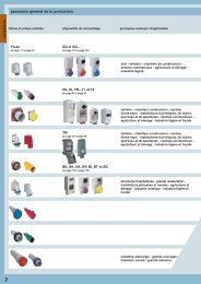
download - Ilme SpA
download - Ilme SpA
download - Ilme SpA

You also want an ePaper? Increase the reach of your titles
YUMPU automatically turns print PDFs into web optimized ePapers that Google loves.
TM interlocked switched sockets<br />
for industrial use<br />
i<br />
ENGLISH
The Company and the Product<br />
INDUSTRIA LOMBARDA MATERIALE ELETTRICO <strong>SpA</strong> has been operating in<br />
Milan since 1938, in particular in the electrotechnical sector for the manufacturing<br />
of equipment for industrial installations.<br />
ILME reflects the traditional entrepreneurial spirit of Lombardy, and has enjoyed<br />
continuous expansion for over half a century.<br />
The company has carved an important role for itself in the main world markets,<br />
also operating directly in the countries that have assumed world leadership in the<br />
field of automation, including Germany and Japan.<br />
In the electrical connection sector with applications in industrial automation,<br />
characterised by top performance and utmost reliability needs, ILME is today the<br />
acknowledged partner of many leading companies worldwide.<br />
The company’s fundamental values are:<br />
product innovation, original solutions, excellent price-quality ratio, a<br />
customer-oriented sense of service, ethical behaviour and an<br />
environmentally-friendly approach.<br />
CE marking<br />
As from 1 January 1997, in order to launch electrical products on the European<br />
market the manufacturer must ensure these bear the relevant CE marking, in line with<br />
the Low Voltage Directive 73/23/EEC * (implemented in Italy as law 18-10-1977<br />
no. 791) and its modification 93/68/EEC * (implemented in Italy as L. D.<br />
25-11-1996 no. 626/96, published in the supplement to the Gazzetta Ufficiale of<br />
14-12-1996).<br />
Said marking must be placed on the product - or, if this is not possible, on the packaging,<br />
the instructions for use or the warranty certificate - and acts as a declaration by the<br />
manufacturer that the product complies with all relevant EU directives.<br />
ILME products bear the CE marking on the product or packaging.<br />
Almost all ILME products fall under the Low Voltage Directive.<br />
All SELV socket-outlets with safety transformer, which are fitted with a magnetic<br />
transformer, also fall within the field of application of the electromagnetic compatibility<br />
directive 89/336/EEC (implemented in Italy as<br />
D.L. 4-12-1992 no. 476 amended by the above<br />
mentioned directive 93/68/EEC), which they conform<br />
to, without the need of testing. A declaration<br />
of compliance is required before applying the CE<br />
marking.<br />
This document, to which the market is not directly<br />
entitled, must be made available to the control<br />
authorities (in Italy the Ministry for Industry,<br />
Commerce and Handicraft) at all times.<br />
In it, the manufacturer declares the technical<br />
safety standard(s) followed to manufacture the<br />
product.<br />
These standards must be, in decreasing order of<br />
preference:<br />
- a European standard (EN prefix)<br />
- a European harmonisation document (HD prefix)<br />
- an international IEC standard<br />
- a national standard<br />
- in the absence of reference standards, the<br />
manufacturer’s internal specifications,<br />
guaranteeing compliance with the directive’s<br />
basic safety requirements.<br />
To promote the continuing improvement of its qualitative results, ILME has<br />
always encouraged its collaborators to work with utmost responsibility and<br />
participation.<br />
The company focuses on a series of benefits to the user, including research into<br />
the most suitable materials, high quality and safe cabling, a rapid turnaround and<br />
readily available services.<br />
Compliance with harmonised technical standards<br />
(i.e. ratified by the CENELEC) constitutes presumed<br />
conformity to the directive’s basic safety<br />
requirements.<br />
The CE marking of ILME products results from<br />
said products’ declaration of conformity to<br />
harmonised standards or international IEC<br />
standards.<br />
Through the CE marking, ILME declares full<br />
compliance, not merely with the directive’s basic<br />
safety requirements, but also with those<br />
international or national EU standards on which<br />
voluntary safety certification markings are based (e.g. IMQ and VDE).<br />
In this way, ILME intends to award the CE marking the value of self-certification in<br />
terms of safety, given the loss in legal value of voluntary certifications issued by third<br />
parties, ratified by directive 93/68/EEC *.<br />
Notwithstanding the above, practically all ILME products still bear voluntary conformity<br />
markings and are in accordance with the RoHS European Directive.<br />
* Note:<br />
new legal reference for the Low Voltage Directive is 2006/95/EC which is the<br />
consolidated edition of Directive 73/23/EEC + Directive 93/68/EEC.<br />
Certifications<br />
Almost all the articles illustrated in this catalogue are certified by the Italian Quality<br />
Mark Institute as indicated by the IMQ mark (see the mark reported on the side of<br />
each article).<br />
The information contained in this catalogue is not binding and may be changed<br />
without prior notice.<br />
Certification ISO 9001: 2008<br />
Design, manufacture and distribution of industrial electrical equipment (IAF 19, 29a)<br />
Certificate No. 50 100 11133
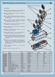
TM interlocked socket-outlets for industrial use<br />
The TM Series has been developed using innovative design ideas and the latest production technology methods (patented BC-MUL System) characterizing<br />
the ILME solution to the latest market needs.<br />
The optimum quality/price relationship combined with an easy to use system, offers a wide range of installation solutions.<br />
TM Series uses electrical components (switches, fuse carriers, female inserts) of tested quality, fixed on a robust supporting frame (die cast) with safety<br />
blocks to provide reliability in service.<br />
Innovative technology<br />
Stability, rigid sections and high<br />
mechanical resistance to shocks<br />
up to 20J are some of the main<br />
features of cases.<br />
The double degree of protection<br />
IP66/IP67, together with the<br />
thermoplastic material used<br />
(MIL.BOX) and the external stainless<br />
steel screws, ensures a high<br />
protection against atmospheric<br />
and aggressive chemical agents,<br />
as well as against UV rays.<br />
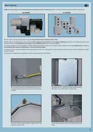
Case<br />
The cases provide protection<br />
independently from the frame<br />
supporting the electrical<br />
components.<br />
The 5 mm thick case walls,<br />
captive metric screws to be<br />
screwed into brass threaded<br />
holes, walls of cases unpierced<br />
marked with the cutting<br />
position, colour grey RAL 7012<br />
are some of the exclusive<br />
features of the series.<br />
The wide range of interlocked<br />
socket-outlets and accessories<br />
(boxes and plates for set<br />
mounting) allows several<br />
combinations.<br />
184 mm<br />
1
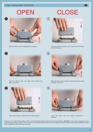
Frame<br />
The frame supporting the electrical components can be removed from the cases and allows the easy installation of the empty cases and external wiring<br />
accessories.<br />
Once the cases are installed, it is very easy to fix the frame by means of a hinge and then proceed with the wiring operation.<br />
2
Features of the series<br />
The TM Series offers many innovative design features for safety and practical applications.<br />
Design features:<br />
- non deformable blocks (die cast).<br />
- double insulation.<br />
- brass threaded holes.<br />
- safety lock systems on fuse carrier cover.<br />
- lockable handle in open/closed position.<br />
- cover for fuse carrier with seats for spare fuses.<br />
- pre-wired conductors to allow the mounting of automatic devices.<br />
- 32A/63A controls with pre-load (that ensure a greater robustness in case of improper use without plug).<br />
- External screws available in two sizes, in stainless steel.<br />
Metal locking lever 32A - 63A controls with pre-load Threaded seats<br />
lockable handle in open/closed position seats for spare fuses facility to mount modular devices<br />
3
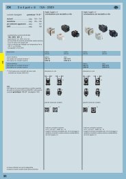
Range<br />
A complete series of interlocked switched sockets<br />
(16-32-63A).<br />
Are available in the following versions:<br />
- with screw-type fuse carriers TM IT/SIT.<br />
- with sectionable fuse carriers TM IS/KIS - SIS/KSIS.<br />
- with DIN-rail for modular equipment TM IR/KIR -<br />
SIR/KSIR.<br />
- Without protection, direct wiring: TM SP/KSP -<br />
SSP/KSSP.<br />
The socket-outlet with transformer is a very<br />
compact unit and can be mounted either in double<br />
or triple boxes.<br />
4
Summary<br />
TM...IT<br />
interlocked switched<br />
socket-outlets<br />
and screw-type fuse<br />
carriers<br />
16A, 32A, 63A (IP66/IP67)<br />
pages 10-11<br />
TM...IS/KIS<br />
pages 12-13<br />
interlocked switched<br />
socket-outlets<br />
with sectionable<br />
fuse carriers<br />
IS - 16A, 32A, 63A (IP66/IP67)<br />
KIS - 32A (IP66/IP67)<br />
TM...IR/KIR<br />
interlocked socket-outlets<br />
with compartment<br />
for modular units<br />
IR - 16A, 32A, 63A (IP66/IP67)<br />
KIR - 32A (IP66/IP67)<br />
pages 14-15<br />
TM...SP/KSP<br />
interlocked switched<br />
socket-outlets<br />
SP - 16A, 32A, 63A (IP66/IP67)<br />
KSP - 32A (IP66/IP67)<br />
pages 16-17<br />
TM...SIT<br />
interlocked switched<br />
socket-outlets<br />
and screw-type fuse<br />
carriers<br />
without base box<br />
16A (IP66/IP67)<br />
page 18 TM...SIS/KSIS<br />
interlocked switched<br />
socket-outlets<br />
with sectionable<br />
fuse carriers<br />
without base box<br />
SIS - 16A (IP66/IP67)<br />
KSIS - 32A (IP66/IP67)<br />
page 19<br />
TM...SIR/KSIR<br />
interlocked socket-outlets, with<br />
compartment for modular units,<br />
without base box<br />
SIR - 16A (IP66/IP67)<br />
KSIR - 32A (IP66/IP67)<br />
page 20<br />
TM...SSP/KSSP<br />
interlocked switched<br />
socket-outlets<br />
without base box<br />
SSP - 16A (IP66/IP67)<br />
KSSP - 32A (IP66/IP67)<br />
page 21<br />
TM 16220 T1 (with base box)<br />
TM 16220 ST1 (without base box)<br />
socket-outlets with safety<br />
transformer<br />
16A (IP66/IP67)<br />
page 22<br />
TM<br />
TM 1145/1456 TB<br />
TM TXT<br />
modular back plates<br />
fixing plug to fit up in the plates<br />
page 24 pages 24-25<br />
TM 2345 DT - small<br />
TM 2656 DT - mixed<br />
TM 2956 DT - big<br />
modular bases<br />
TM 1114 DB<br />
TM 1414 DB<br />
enclosures for<br />
modular equipments<br />
IP66/IP67<br />
page 26<br />
TM 2314 DB<br />
TM 2614 DB<br />
TM 2914 DB<br />
enclosures for<br />
modular equipments<br />
page 26<br />
TM 1114 GB<br />
TM 1414 GB<br />
Boxes for modular units<br />
page 27<br />
TM 2314 GB<br />
TM 2614 GB<br />
TM 2914 GB<br />
Boxes for modular units<br />
page 27<br />
IP66/IP67<br />
IP66/IP67<br />
IP66/IP67<br />
TM 1125 CS<br />
page 28<br />
TM 2344 T2<br />
TM 3444 T3<br />
page 28 page 29<br />
TM 1125 P<br />
single box<br />
double box<br />
triple box<br />
cover boxes<br />
TM 2318 P2<br />
TM 3418 P3<br />
TM 2318 R2<br />
TM 3418 R3<br />
covers to close<br />
compartments<br />
page 29<br />
TM 1125 PF<br />
TM 1114 PF, TM 1414 PF, TM 2314<br />
PF<br />
TM 2614 PF, TM 2914 PF<br />
mounting and fixing plates<br />
page 30<br />
TM GD8/10/18/21/24<br />
BC FR 62<br />
BC CHT<br />
DIN EN 60715 guide<br />
satefy block with key<br />
plates for empty spaces<br />
page 30<br />
page 31<br />
page 31<br />
AS-AR-AF<br />
pages 32-33-34<br />
Q<br />
QP V<br />
boards for<br />
construction site<br />
QG V<br />
boards for<br />
construction site<br />
FC NP<br />
insulating<br />
cable-gland<br />
complementary<br />
parts<br />
NEW<br />
5
Overview of TM socket-outlets with mechanical interlock<br />
Wall-mounting, with<br />
single box<br />
TM...IT<br />
For assembly in<br />
single or multiple boxes<br />
TM...IT<br />
TM...SIT<br />
32A / 63A<br />
16A<br />
16A<br />
TM...IS<br />
TM...IS/KIS<br />
TM...SIS/KSIS<br />
32A / 63A<br />
16A / 32A<br />
16A / 32A<br />
TM...IR<br />
TM...IR/KIR<br />
TM...SIR/KSIR<br />
32A / 63A<br />
16A / 32A<br />
16A / 32A<br />
TM...SP<br />
TM...SP/KSP<br />
TM...SSP/KSSP<br />
32A / 63A<br />
16A / 32A<br />
16A / 32A<br />
TM...T1<br />
TM...ST1<br />
With transformer<br />
With transformer<br />
TM...K..<br />
= 32A socket-outlets with 255 x 114 mm fixing base<br />
6
Overview of TM interlocked socket-outlets and accessories for group mounting<br />
5<br />
11<br />
12<br />
14<br />
4<br />
7<br />
13<br />
15<br />
6<br />
2<br />
10<br />
1<br />
●<br />
3<br />
9<br />
●<br />
8<br />
18<br />
17<br />
16<br />
21<br />
19<br />
20<br />
24<br />
A<br />
23<br />
22<br />
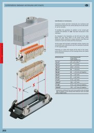
TM accessories<br />
A<br />
B<br />
1 = TM 1145 TB (page 24)<br />
2 = TM 1456 TB (page 24)<br />
3 = TM TXT (page 24)<br />
4 = TM 1114 DB (page 26)<br />
5 = TM 1414 DB (page 26)<br />
6 = TM 1114 GB (page 27)<br />
7 = TM 1414 GB (page 27)<br />
8 = TM 1125 CS (page 28)<br />
9 = TM 2344 T2 (page 28)<br />
10 = TM 3444 T3 (page 28)<br />
11 = TM 1125 P (page 29)<br />
12 = TM 2318 P2 (page 29)<br />
13 = TM 2318 R2 (page 29)<br />
14 = TM 3418 P3 (page 29)<br />
15 = TM 3418 R3 (page 29)<br />
16 = TM 2314 DB (page 26)<br />
17 = TM 2614 DB (page 26)<br />
18 = TM 2914 DB (page 26)<br />
19 = TM 2314 GB (page 27)<br />
20 = TM 2614 GB (page 27)<br />
21 = TM 2914 GB (page 27)<br />
22 = TM 2345 DT (page 24)<br />
23 = TM 2656 DT (page 25)<br />
24 = TM 2956 DT (page 25)<br />
Legend<br />
The list above shows all the possible combinations of socket-outlets, back plates and enclosures that can be used to configure distribution systems.<br />
The coloured point near to the socket-outlets indicates their size, while the arrows (in the matching colour) indicate the assembly options.<br />
A = Socket-outlets with 255 x 114 mm fixing base<br />
B = Socket-outlets with 370 x 144 mm fixing base<br />
7
TM interlocked switched socket-outlets for industrial use<br />
General characteristics<br />
This chapter illustrates the characteristics of TM series interlocked socket-outlets.<br />
These socket-outlets offer tested reliability and can be used, in combination with special<br />
complementary parts and PLUSO industrial plugs, as modular integrated systems<br />
to configure distribution systems with industrial socket-outlets.<br />
These socket-outlets are designed to be used for:<br />
- Industrial applications<br />
- Service applications (trade fairs, exhibitions, etc.)<br />
- Agricultural and livestock breeding applications<br />
- Residential and similar applications (i.e. common areas of condominiums, cellars,<br />
garages, community buildings, kitchens, etc.)<br />
Socket-outlets and plugs for industrial use should be selected according to the following<br />
parameters:<br />
• Rated current of the device to supply with the plug and socket-outlet coupling<br />
• Rated supply voltage, type of current (AC or CD), rated frequency, and type of distribution<br />
(single or three-phase, with or without neutral) to determine the number<br />
of poles and hour position<br />
The 1 hour position is available for all 50V voltages and voltage ranges > and for<br />
frequencies and frequency ranges not covered by standards<br />
• Type of installation (fixed or mobile) to determine the construction type of plugs<br />
and socket-outlets (flush-mounting, straight or inclined, wall-mounting, mobile,<br />
mobile angled)<br />
• The site of installation to determine the degree of protection (IP44 or IP67) and<br />
voltage (in some areas installation standards<br />
require very low safety voltage) TM socket-outlets come with base box for flushor<br />
wall-mounting or without box for the assembly on single or multiple TM ILME<br />
boxes (available on request). This enables to configure distribution boards at a<br />
later stage. The following types of socket-outlets are available:<br />
with insulating enclosure with base box:<br />
- TM..IT types with interlock and plug-type fuse carrier<br />
- TM..IS/KIS types with interlock and sectionable fuse carrier<br />
- TM..IR/KIR types with interlock and compartment for modular units<br />
- TM..SP/KSP types with interlock (without fuse carrier)<br />
- TM..T1 types with safety transformer (for extra-low voltage, SELV 24V AC)<br />
with insulating enclosure without base box (only for 16A and 32A socket-outlets):<br />
- TM..SIT types with interlock and plug-type fuse carrier<br />
- TM..SIS/KSIS types with interlock and sectionable fuse carrier<br />
- TM..SIR/KSIR types with interlock and compartment for modular units<br />
- TM..SSP/KSSP types with interlock (without fuse carrier)<br />
- TM..ST1 types with safety transformer (for extra-low voltage, SELV 24V AC)<br />
The type references of these last types is the same as those of models with boxes.<br />
Types with base box can be wall-mounted or flush-mounted, if required.<br />
The high solidity of boxes and materials used enable these products to be installed<br />
in reinforced concrete casts.<br />
Installers shall be responsible for performing the electric connections, preparing the<br />
entry holes on the boxes using the centering points on the sides, and for completing<br />
the installation using hardware with a suitable degree of protection.<br />
The class of IP protection of the equipment will be equivalent to that resulting from<br />
the compliance with workmanship procedures and from the use of cable entries with<br />
an equivalent or higher IP degree of protection.<br />
The degree of protection of the equipment is always equivalent to the lowest one of<br />
the installed units.<br />
Types without base boxes can be mounted on existing and installed single or multiple<br />
boxes or on new ones, which can be purchased separately.<br />
Socket-outlets can also be fitted with specifically designed complementary parts to<br />
configure group distribution systems suitable to meet all possible installation needs.<br />
Socket-outlets can be fitted with:<br />
- Back plates in two sizes (depending on the size of the socket-outlet enclosure), suitable<br />
for the assembly of socket-outlets with boxes or boxes for future expansion<br />
- Boxes for modular units like protection and control equipment<br />
- Junction boxes for socket-outlets or boxes<br />
- Modular pre-assembled bases<br />
- Single or multiple boxes for the subsequent installation of TM socket-outlets for<br />
board mounting<br />
Socket-outlets and boxes for modular units (boxes with compartment for modular<br />
units) are suitable to be used to spring-lock modular units (17.5 mm base modules)<br />
with sized DIN-rail EN 60715 TH 35-7.5.<br />
For information on the number of modules and maximum power that can be dissipated,<br />
see Table 1.<br />
Socket-outlet electric characteristics<br />
rated frequency:<br />
0 Hz (direct current), and from 50 Hz to 500 Hz<br />
rated operating voltage:<br />
the standard identifies two main types of use:<br />
- Extra-low voltage socket-outlets (and related plugs), (SELV safety requirements, in<br />
accordance with the CEI 64-8 installation standard), for max. rms voltage values of<br />
50V<br />
- Low voltage socket-outlets (plugs) for rms voltage values above 50V, up to a maximum<br />
of 690V<br />
polarity:<br />
models are designed with:<br />
- 2 poles (extra-low voltage, 2P)<br />
- 3, 4 and 5 poles (low voltage, 2P+m, 3P+m, 3P+N+m);<br />
63A socket-outlets (and related plugs) also have an additional pilot contact<br />
rated current:<br />
with 16A, 32A and 63A values (low voltage)<br />
rated insulation voltage:<br />
- 690V for low voltage socket-outlets parts. The rated insulating voltage of the<br />
whole assembly generally corresponds to that of the lowest component and is limited<br />
to 500V thanks to the presence of IS/SIS and IT/SIT fuse carriers.<br />
- 50V for extra-low voltage parts (T1/ST1 types always have an insulated transformer<br />
with a rated insulation voltage of 230V on the primary circuit)<br />
minimum surface insulation distance:<br />
6 mm for max. rated operating voltages of 500V (EN 60309-1)<br />
minimum air insulation distance:<br />
6 mm for maximum rated operating voltages of 500V<br />
breaking capacity:<br />
socket-outlets have mechanical interlocks that prevent the plug being removed while<br />
voltage is present or from being inserted when the socket-outlet is live. This explains<br />
why no breaking capacity is required. The socket-outlets parts (inserts and holes) are<br />
the same as those of the Pluso series and have therefore a breaking power 1.25<br />
times the rated current and 1.1 times the rated operating voltage.<br />
rated shortcircuit current based on fuse:<br />
10kA<br />
electromagnetic compatibility:<br />
these units do not fall within the field of application of the EMC Directive, except for<br />
socket-outlets with safety transformer (T1/ST1 types).<br />
- Immunity: in ordinary operating conditions, these units are not affected by electromagnetic<br />
noise. This may not apply if the installer has fitted devices that are sensitive<br />
to electromagnetic noise in ordinary operating conditions.<br />
- Emissions: all units are designed for continuous use and do not generate electromagnetic<br />
noise in ordinary operating conditions. This may not apply if the installer<br />
has fitted devices that generate electromagnetic noise in ordinary operating conditions.<br />
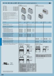
Mechanical characteristics<br />
- mechanical resistance to impacts<br />
20J (IK10 in accordance with EN 50102)<br />
- resistance to chemical agents<br />
see Table on page 35<br />
- degree of protection<br />
IP66/IP67 according to EN 60529 (see information note on pages 9)<br />
- maximum dissipating power of the enclosure<br />
see table on page 9<br />
- resistance to glow-wire<br />
self-extinguishing capacity compliant with IEC 695-2-1 (glow-wire) for enclosures<br />
650 °C; for inserts 960 °C (value specified in standard: 850 °C)<br />
- temperature<br />
ambient: -25 °C - +40 °C; limit of materials: -40 °C - +90 °C<br />
- self-extinguishing capacity<br />
UL 94 classification<br />
- for enclosures (boxes and/or covers of fixed socket-outlets, enclosures of mobile<br />
plugs and socket-outlets): 94V-2 and 94HB<br />
- for 16A and 32A inserts (socket-outlet and plug): 94V-2<br />
- for 63A inserts (socket-outlet and plug): 94-5VA and 94V-0<br />
Materials<br />
- Inserts in insulating self-extinguishing thermoplastic material<br />
- Enclosures in insulating self-extinguishing thermoplastic material MIL.BOX ® , printed<br />
with BC-MUL ® system, RAL 7012 grey<br />
- Anti-aging elastomer gaskets<br />
- Self-centering elastic brass contact tubes with zinc-plated steel spring<br />
- Fixing retainer screws in stainless steel with cylindrical head and mixed slots for 8x1<br />
screwdrivers and Ph2 cross screwdrivers<br />
- Terminals with zinc-plated screws retained in their seats when unscrewed<br />
- 32A and 63A socket-outlets with two fixing screws in the terminals as protection<br />
against accidental loss<br />
- Terminals of 63A socket-outlets fitted with lead protection plate in zinc-plated steel<br />
TM socket-outlets, compliant with the European harmonized safety standards EN<br />
60309-1 and EN 60309-2 satisfy the law requirements of applicable directives<br />
(73/23/EEC and subsequent amendments). Types for low voltage (V>50V), that fall<br />
within the field of application of the above-mentioned directives, are marked EC.<br />
This marking was introduced as compulsory on January 1st 1997.<br />
Supply extension<br />
Socket-outlets without box can be supplied with:<br />
- Boxes for the assembly of simple, double or triple socket-outlets (purchasable<br />
separately), insulating separators for the entry/shunting area and a panel with<br />
alveolated base<br />
Socket-outlets with boxes can be supplied with:<br />
- Standard back plates<br />
- Junction boxes<br />
- Boxes for modular units<br />
- Modular pre-assembled bases (with box for modular units)<br />
8
TM interlocked prese per usi socket-outlets industriali con for dispositivo industrial use di blocco<br />
Degree of protection<br />
The degree of protection should be chosen according to installation standard CEI 64-8 (that implements harmonized documents CENELEC series HD 384 and IEC 60364),<br />
whose section 7 refers to specific types of installations, such as: construction and demolition sites, structures designed for agricultural or livestock breeding use, restricted conductor<br />
areas, caravans and caravan sites, environments with higher fire hazards, public performance and entertainment areas, pools and, in the future, fountains and marinas<br />
and harbour areas.<br />
TM interlocked socket-outlets have a double IP6/IP67 degree of protection. Socket-outlets with IP66/IP67 degree of protection have a bayonet fastening cover, traditionally<br />
defined as “water-tight”, and must be used with with IP67 plugs (with locking ring and gasket) to guarantee a high protection of the connected equipment. To be able to perform<br />
the required electric connections, it is necessary to drill holes on the boxes, using the centering holes, and use appropriate hardware for assembly purposes.<br />
The class of IP protection of the equipment will be equivalent to that resulting from the compliance with workmanship procedures and from the use of cable entries with an equivalent<br />
or higher IP degree of protection. If components with different degrees of protection are installed, the degree of protection of the distribution board or system shall be equivalent<br />
to that of the component with the lowest degree of protection. If the degree of protection of cable entries (cable, pipe and gasket glands) is equivalent or above the one<br />
marked on the socket-outlets, the IP degree of protection shall be assessed and applies:<br />
- To socket-outlets when a plug with equivalent class is inserted or the cover is closed<br />
- To enclosures, when all covers are closed<br />
ILME accessories for TM socket-outlets<br />
TM socket-outlets can be used with the following range of plugs, back plates and enclosures:<br />
- Pluso industrial socket-outlets in two standard versions with IP44 and IP67 degree of protection: PE and PEW, SIP and SIPW (phase inverters), PEM types (monobloc with 5<br />
poles)<br />
- Ordinary back plates (TM 1145 TB and TM 1456 TB types)<br />
- Junction boxes (TM…DB types) in 5 sizes<br />
- Boxes for modular units (TM…GB types) in 5 sizes<br />
- Modular pre-assembled bases with two back plates and box for modular units (TM…DT types)<br />
- Boxes for single socket-outlets (TM 1125 CS types), double boxes (TM 2344 T2 types) and triple boxes (TM 3444 T3 types).<br />
All socket-outlets, back plates and enclosures cover the installation requirements specified in standard CEI 64-8 (series CENELEC HD 384, IEC 60364).<br />
Application of draft standard CEI 23-51<br />
The maximum power that can be dissipated, P inv , has been tested for each box in the most severe operating conditions<br />
using the method described in draft standard CEI 23-49. Results are shown in Table 1.<br />
Maximum dissipating power of enclosure Pinv (CEI 23-49)<br />
Table 1<br />
Item Description Number of Pinv 1) (W) Pinv (W)<br />
modules wall-mounting flush-mounting<br />
TM 1114 GB 115 x 144 mm box 4 units 8 10<br />
TM 1414 GB 144 x 144 mm box 5.5 units 10 13<br />
TM 2314 GB 230 x 144 mm box 10 units 13 16<br />
TM 2614 GB 260 x 144 mm box 12 units 15 19<br />
TM 2914 GB 290 x 144 mm box 13.5 units 17 22<br />
TM 2344 T2 double box 10 units 13 18<br />
TM 3444 T3 triple box 16.5 units 20 26<br />
NOTE: the maximum power that can be dissipated, P inv , is identified with suffix GB “box for<br />
modular units”, specifically designed to house modular units that can be assessed from the hinged door. The<br />
same amount of power can also be dissipated in models with DB suffix “junction box”.<br />
1)<br />
Determined for each enclosure size under the most severe load conditions provided for in the standard.<br />
9
TM.. IT interlocked switched socket-outlets with fuse-carrier for screw-type fuses<br />
● Compliant with EN 60309 -1, -2 and 4<br />
● Enclosures in insulating self-extinguishing thermoplastic<br />
material, RAL 7012 grey<br />
● Mechanical resistance to impacts: 20 J (IK 10 as<br />
EN 50102)<br />
● Socket-outlets with bayonet fastening cover<br />
● Factory installed internal wiring<br />
● Cable entry with drilling template<br />
● “Zeta” switch with I th = 32A rating (in air) and I the =<br />
32A (in enclosure) for 16A and 32A socket-outlets<br />
● Mechanical interlock that prevents:<br />
the switch from being turned on without the plug<br />
inserted and the plug from being removed while the<br />
switch is on<br />
● Knob lockable in positions O and I<br />
● Compartment with plug-type fuse carrier (fuses not<br />
supplied) and inspection panel openable only when<br />
the switch is off<br />
● q With Italian Quality Mark<br />
16A<br />
IP66/IP67 degree of protection<br />
Rated<br />
current<br />
Maximum<br />
operating<br />
Fuse carrier<br />
type<br />
socket part current<br />
16A 16A E16 - 25A-500V<br />
Poles Frequency Voltage Earthing contact Part No. Colour<br />
Hz V position h<br />
2P+m 50 and 60 100 - 130 4 TM 1643 IT q<br />
50 and 60 200 - 250 6 TM 1663 IT q<br />
50 and 60 380 - 415 9 TM 1693 IT q<br />
50 and 60 480 - 500 7 TM 1673 IT q<br />
50 and 60 ins. transformer 12 TM 16123 IT q A.V.<br />
> 300 - 500 > 50 2 TM 1623 IT q * )<br />
d.c. > 50 - 250 3 TM 1633 IT q A.V.<br />
3P+m 50 and 60 100 - 130 4 TM 1644 IT q<br />
50 and 60 200 - 250 9 TM 1694 IT q<br />
50 and 60 380 - 415 6 TM 1664 IT q<br />
60 440 - 460 11 TM 16114 IT q<br />
50 and 60 480 - 500 7 TM 1674 IT q<br />
50 380 3 TM 1634 IT q<br />
60 440 3 TM 1634 IT q<br />
100 - 300 > 50 10 TM 16104 IT q * )<br />
> 300 - 500 > 50 2 TM 1624 IT q * ) )<br />
3P+N+m 50 and 60 57/100 - 75/130 4 TM 1645 IT q<br />
50 and 60 120/208 - 144/250 9 TM 1695 IT q<br />
50 and 60 200/346 - 240/415 6 TM 1665 IT q<br />
50 and 60 277/480 - 288/500 7 TM 1675 IT q<br />
60 250/440 - 265/460 11 TM 16115 IT q<br />
50 220/380 3 TM 1635 IT q<br />
60 250/440 3 TM 1635 IT q<br />
> 300 - 500 > 50 2 TM 1625 IT q * ) )<br />
Legend<br />
A.V. = Colour according to voltage<br />
*) Green may be used together with the colour of the<br />
operating range for frequencies above 60 Hz and up<br />
to a maximum of 500 Hz<br />
dimensions in mm<br />
Center for hole<br />
Accessories for socket-outlet combinations<br />
TM 1145 TB<br />
(page 24)<br />
with 1 plate<br />
TM 1114 DB<br />
(page 26)<br />
with 2 plates<br />
255 B<br />
(page 26)<br />
TM 1114 GB<br />
(page 27)<br />
(page 27)<br />
114 A<br />
Accessories for assembly on control panels<br />
QP V - QG V<br />
205<br />
page 31<br />
Ø 5<br />
97<br />
Poles A B<br />
2P + m 133 276<br />
3P + m 135 276<br />
3P+N+m 140 277<br />
Dimensions indicated are not binding and may be<br />
changed without prior notice.<br />
10
TM.. IT interlocked switched socket-outlets with fuse-carrier for screw-type fuses<br />
● Compliant with EN 60309 -1, -2 and 4<br />
● Enclosures in insulating self-extinguishing thermoplastic<br />
material, RAL 7012 grey<br />
● Mechanical resistance to impacts: 20 J (IK 10 as<br />
EN 50102)<br />
● Socket-outlets with bayonet fastening cover<br />
● 63A types with pilot contact<br />
● Factory installed internal wiring<br />
● Cable entry with drilling template<br />
● “Zeta” switch I th = 80A (in air) and I the = 63A (in<br />
enclosure) for 32A and 63A socket-outlets<br />
● Mechanical interlock that prevents:<br />
the switch from being turned on without the plug<br />
inserted and the plug from being removed while the<br />
switch is on<br />
● Knob lockable in positions O and I<br />
● Compartment with plug-type fuse carrier (fuses not<br />
supplied) and inspection panel openable only when<br />
the switch is off<br />
● q With Italian Quality Mark<br />
Rated Fuse carrier<br />
current type<br />
32A E33 - DIII - 35A-500V<br />
63A E33 - DIII - 63A-500V<br />
32A<br />
IP66/IP67 degree of protection<br />
63A<br />
IP66/IP67 degree of protection<br />
Poles Frequency Voltage Earthing contact Part No. Colour Part No. Colour<br />
Hz V position h<br />
2P+m 50 and 60 100 - 130 4 TM 3243 IT q TM 6343 IT q<br />
50 and 60 200 - 250 6 TM 3263 IT q TM 6363 IT q<br />
50 and 60 380 - 415 9 TM 3293 IT q TM 6393 IT q<br />
50 and 60 480 - 500 7 TM 3273 IT q TM 6373 IT q<br />
50 and 60 ins. transformer 12 TM 32123 IT q A.V. TM 63123 IT q A.V.<br />
> 300 - 500 > 50 2 TM 3223 IT q * )<br />
d.c. > 50 - 250 3 TM 3233 IT q A.V.<br />
3P+m 50 and 60 100 - 130 4 TM 3244 IT q TM 6344 IT q<br />
50 and 60 200 - 250 9 TM 3294 IT q TM 6394 IT q<br />
50 and 60 380 - 415 6 TM 3264 IT q TM 6364 IT q<br />
60 440 - 460 11 TM 32114 IT q TM 63114 IT q<br />
50 and 60 480 - 500 7 TM 3274 IT q TM 6374 IT q<br />
50 380 3 TM 3234 IT q<br />
60 440 3 TM 3234 IT q<br />
100 - 300 > 50 10 TM 32104 IT q * )<br />
> 300 - 500 > 50 2 TM 3224 IT q * )<br />
3P+N+m 50 and 60 57/100 - 75/130 4 TM 3245 IT q TM 6345 IT q<br />
50 and 60 120/208 - 144/250 9 TM 3295 IT q TM 6395 IT q<br />
50 and 60 200/346 - 240/415 6 TM 3265 IT q TM 6365 IT q<br />
50 and 60 277/480 - 288/500 7 TM 3275 IT q TM 6375 IT q<br />
60 250/440 - 265/460 11 TM 32115 IT q TM 63115 IT q<br />
50 220/380 3 TM 3235 IT q<br />
60 250/440 3 TM 3235 IT q<br />
> 300 - 500 > 50 2 TM 3225 IT q * )<br />
Legend<br />
A.V. = Colour according to voltage<br />
*) Green may be used together with the colour of the<br />
operating range for frequencies above 60 Hz and up<br />
to a maximum of 500 Hz<br />
dimensions in mm<br />
Center for hole<br />
dimensions in mm<br />
Center for hole<br />
Accessories for socket-outlet combinations<br />
TM 1456 TB<br />
(page 24)<br />
with 1 plate<br />
TM 1414 DB<br />
(page 26)<br />
with 2 plates<br />
370 398<br />
370 415<br />
(page 26)<br />
TM 1414 GB<br />
(page 27)<br />
(page 27)<br />
144 A<br />
144 178<br />
Accessories for assembly on control panels<br />
QP V - QG V<br />
page 31<br />
Ø 5<br />
320<br />
Poles A<br />
2P+m 162<br />
3P+m 162<br />
3P+N+m 169<br />
Ø 5<br />
320<br />
Dimensions indicated are not binding and may be<br />
changed without prior notice.<br />
127<br />
127<br />
11
TM.. IS/KIS interlocked socket-outlets and sectionable fuse carrier<br />
● Compliant with EN 60309 -1, -2 and 4<br />
● Enclosures in insulating self-extinguishing thermoplastic<br />
material, RAL 7012 grey<br />
● Mechanical resistance to impacts: 20 J (IK 10 as<br />
EN 50102)<br />
● Socket-outlets with bayonet fastening cover<br />
● Factory installed internal wiring<br />
● Cable entry with drilling template<br />
● “Zeta” switch with I th = 32A rating for 16A and 32A<br />
socket-outlets<br />
● Mechanical interlock that prevents:<br />
the switch from being turned on without the plug<br />
inserted and the plug from being removed while the<br />
switch is on<br />
● Knob lockable in positions O and I<br />
● Compartment with sectionable fuse carrier (fuses<br />
not supplied) and inspection panel openable only<br />
when the switch is off<br />
● q With Italian Quality Mark<br />
Rated courrent Maximum Fuse carrier<br />
socket part operating current CH type<br />
16A 16A 10 x 38<br />
32A 32A 10 x 38<br />
16A<br />
IP66/IP67 degree of protection<br />
32A<br />
IP66/IP67 degree of protection<br />
Poles Frequency Voltage Earthing contact Part No. Colour Part No. Colour<br />
Hz V position h<br />
2P+m 50 and 60 100 - 130 4 TM 1643 IS q TM 3243KIS q<br />
50 and 60 200 - 250 6 TM 1663 IS q TM 3263KIS q<br />
50 and 60 380 - 415 9 TM 1693 IS q TM 3293KIS q<br />
50 and 60 480 - 500 7 TM 1673 IS q<br />
50 and 60 ins. transformer 12 TM 16123 IS q A.V. TM 32123KIS q A.V.<br />
> 300 - 500 > 50 2 TM 1623 IS q * ) TM 3223KIS q (up to 400V) * )<br />
d.c. > 50 - 250 3 TM 1633 IS q A.V. TM 3233KIS q A.V.<br />
3P+m 50 and 60 100 - 130 4 TM 1644 IS q TM 3244KIS q<br />
50 and 60 200 - 250 9 TM 1694 IS q TM 3294KIS q<br />
50 and 60 380 - 415 6 TM 1664 IS q TM 3264KIS q<br />
60 440 - 460 11 TM 16114 IS q<br />
50 and 60 480 - 500 7 TM 1674 IS q<br />
50 380 3 TM 1634 IS q TM 3234KIS q<br />
60 440 3 TM 1634 IS q<br />
100 - 300 > 50 10 TM 16104 IS q * ) TM 32104KIS q (up to 400V) * )<br />
> 300 - 500 > 50 2 TM 1624 IS q * ) TM 3224KIS q (up to 400V) * )<br />
3P+N+m 50 and 60 57/100 - 75/130 4 TM 1645 IS q TM 3245KIS q<br />
50 and 60 120/208 - 144/250 9 TM 1695 IS q TM 3295KIS q<br />
50 and 60 200/346 - 240/415 6 TM 1665 IS q TM 3265KIS q<br />
50 and 60 277/480 - 288/500 7 TM 1675 IS q<br />
60 250/440 - 265/460 11 TM 16115 IS q<br />
50 220/380 3 TM 1635 IS q TM 3235KIS q<br />
60 250/440 3 TM 1635 IS q<br />
> 300 - 500 > 50 2 TM 1625 IS q * ) TM 3225KIS q (up to 400V) * )<br />
Legend<br />
A.V. = Colour according to voltage<br />
*) Green may be used together with the colour of the<br />
operating range for frequencies above 60 Hz and up<br />
to a maximum of 500 Hz<br />
dimensions in mm<br />
Center for hole<br />
dimensions in mm<br />
Center for hole<br />
Accessories for socket-outlet combinations<br />
TM 1145 TB<br />
(page 24)<br />
with 1 plate<br />
TM 1114 DB<br />
(page 26)<br />
with 2 plates<br />
255 B<br />
255 285<br />
(page 26)<br />
TM 1114 GB<br />
(page 27)<br />
(page 27)<br />
114 A<br />
114 A<br />
Accessories for assembly on control panels<br />
QP V - QG V<br />
205<br />
205<br />
page 31<br />
Ø 5<br />
97<br />
Poles A B<br />
2P+m 133 276<br />
3P+m 135 276<br />
3P+N+m 140 277<br />
Ø 5<br />
97<br />
Poles A<br />
2P+m 146<br />
3P+m 146<br />
3P+N+m 151<br />
Dimensions indicated are not binding and may be<br />
changed without prior notice.<br />
12
TM.. IS interlocked socket-outlets and sectionable fuse carrier<br />
● Compliant with EN 60309 -1, -2 and 4<br />
● Enclosures in insulating self-extinguishing thermoplastic<br />
material, RAL 7012 grey<br />
● Mechanical resistance to impacts: 20 J (IK 10 as<br />
EN 50102)<br />
● Socket-outlets with bayonet fastening cover<br />
● 63A types with pilot contact<br />
● Factory installed internal wiring<br />
● Cable entry with drilling template<br />
● “Zeta” switch I th = 80A (in air) and I the = 63A (in<br />
enclosure) for 32A and 63A socket-outlets<br />
● Mechanical interlock that prevents:<br />
the switch from being turned on without the plug<br />
inserted and the plug from being removed while the<br />
switch is on<br />
● Knob lockable in positions O and I<br />
● Compartment with sectionable fuse carrier (fuses<br />
not supplied) and inspection panel openable only<br />
when the switch is off<br />
● q With Italian Quality Mark<br />
Rated current Fuse carrier type CH<br />
32A 14 x 51<br />
63A 22 x 58<br />
32A<br />
IP66/IP67 degree of protection<br />
63A<br />
IP66/IP67 degree of protection<br />
Poles Frequency Voltage Earthing contact Part No. Colour Part No. Colour<br />
Hz V position h<br />
2P+m 50 and 60 100 - 130 4 TM 3243 IS q TM 6343 IS q<br />
50 and 60 200 - 250 6 TM 3263 IS q TM 6363 IS q<br />
50 and 60 380 - 415 9 TM 3293 IS q TM 6393 IS q<br />
50 and 60 480 - 500 7 TM 3273 IS q TM 6373 IS q<br />
50 and 60 ins. transformer 12 TM 32123 IS q A.V. TM 63123 IS q A.V.<br />
> 300 - 500 > 50 2 TM 3223 IS q * )<br />
d.c. > 50 - 250 3 TM 3233 IS q A.V.<br />
3P+m 50 and 60 100 - 130 4 TM 3244 IS q TM 6344 IS q<br />
50 and 60 200 - 250 9 TM 3294 IS q TM 6394 IS q<br />
50 and 60 380 - 415 6 TM 3264 IS q TM 6364 IS q<br />
60 440 - 460 11 TM 32114 IS q TM 63114 IS q<br />
50 and 60 480 - 500 7 TM 3274 IS q TM 6374 IS q<br />
50 380 3 TM 3234 IS q<br />
60 440 3 TM 3234 IS q<br />
100 - 300 > 50 10 TM 32104 IS q * )<br />
> 300 - 500 > 50 2 TM 3224 IS q * )<br />
3P+N+m 50 and 60 57/100 - 75/130 4 TM 3245 IS q TM 6345 IS q<br />
50 and 60 120/208 - 144/250 9 TM 3295 IS q TM 6395 IS q<br />
50 and 60 200/346 - 240/415 6 TM 3265 IS q TM 6365 IS q<br />
50 and 60 277/480 - 288/500 7 TM 3275 IS q TM 6375 IS q<br />
60 250/440 - 265/460 11 TM 32115 IS q TM 63115 IS q<br />
50 220/380 3 TM 3235 IS q<br />
60 250/440 3 TM 3235 IS q<br />
> 300 - 500 > 50 2 TM 3225 IS q * )<br />
Legend<br />
A.V. = Colour according to voltage<br />
*) Green may be used together with the colour of the<br />
operating range for frequencies above 60 Hz and up<br />
to a maximum of 500 Hz<br />
dimensions in mm<br />
Center for hole<br />
dimensions in mm<br />
Center for hole<br />
Accessories for socket-outlet combinations<br />
TM 1456 TB<br />
(page 24)<br />
with 1 plate<br />
TM 1414 DB<br />
(page 26)<br />
with 2 plates<br />
370 398<br />
370 415<br />
(page 26)<br />
TM 1414 GB<br />
(page 27)<br />
(page 27)<br />
144 A<br />
144 178<br />
Accessories for assembly on control panels<br />
QP V - QG V<br />
page 31<br />
Ø 5<br />
320<br />
Poles A<br />
2P+m 162<br />
3P+m 162<br />
3P+N+m 169<br />
Ø 5<br />
320<br />
Dimensions indicated are not binding and may be<br />
changed without prior notice.<br />
127<br />
127<br />
13
TM.. IR/KIR interlocked socket-outlets with compartment for modular units<br />
● Compliant with EN 60309 -1, -2 and 4<br />
● Enclosures in insulating self-extinguishing thermoplastic<br />
material, RAL 7012 grey<br />
● Mechanical resistance to impacts: 20 J (IK 10 as<br />
EN 50102)<br />
● Socket-outlets with bayonet fastening cover<br />
● Factory installed internal wiring<br />
● Cable entry with drilling template<br />
● “Zeta” switch with I th = 32A rating for 16A and 32A<br />
socket-outlets<br />
● Mechanical interlock that prevents:<br />
the switch from being turned on without the plug inserted<br />
and the plug from being removed while the switch is on<br />
● Knob lockable in positions O and I<br />
● Compartment for modular units with DIN-rail EN<br />
60715 (CEI 17-78) TH 35-7,5 and inspection panel<br />
that can be opened only when the switch is off<br />
● q With Italian Quality Mark<br />
Rated of N. of modules Dimensions of the<br />
socket part for mounting of the modular<br />
on 17.5 DIN-rail compartment in mm<br />
16A 4,5 82 x 45<br />
32A 4,5 82 x 45<br />
16A<br />
IP66/IP67 degree of protection<br />
32A<br />
IP66/IP67 degree of protection<br />
Poles Frequency Voltage Earthing contact Part No. Colour Part No. Colour<br />
Hz V position h<br />
2P+m 50 and 60 100 - 130 4 TM 1643 IR q TM 3243KIR q<br />
50 and 60 200 - 250 6 TM 1663 IR q TM 3263KIR q<br />
50 and 60 380 - 415 9 TM 1693 IR q TM 3293KIR q<br />
50 and 60 480 - 500 7 TM 1673 IR q TM 3273KIR q<br />
50 and 60 ins. transformer 12 TM 16123 IR q A.V. TM 32123KIR q A.V.<br />
> 300 - 500 > 50 2 TM 1623 IR q * ) TM 3223KIR q * )<br />
d.c. > 50 - 250 3 TM 1633 IR q A.V. TM 3233KIR q A.V.<br />
3P+m 50 and 60 100 - 130 4 TM 1644 IR q TM 3244KIR q<br />
50 and 60 200 - 250 9 TM 1694 IR q TM 3294KIR q<br />
50 and 60 380 - 415 6 TM 1664 IR q TM 3264KIR q<br />
60 440 - 460 11 TM 16114 IR q TM 32114KIR q<br />
50 and 60 480 - 500 7 TM 1674 IR q TM 3274KIR q<br />
50 380 3 TM 1634 IR q TM 3234KIR q<br />
60 440 3 TM 1634 IR q TM 3234KIR q<br />
100 - 300 > 50 10 TM 16104 IR q * ) TM 32104KIR q * )<br />
> 300 - 500 > 50 2 TM 1624 IR q * ) TM 3224KIR q * )<br />
3P+N+m 50 and 60 57/100 - 75/130 4 TM 1645 IR q TM 3245KIR q<br />
50 and 60 120/208 - 144/250 9 TM 1695 IR q TM 3295KIR q<br />
50 and 60 200/346 - 240/415 6 TM 1665 IR q TM 3265KIR q<br />
50 and 60 277/480 - 288/500 7 TM 1675 IR q TM 3275KIR q<br />
60 250/440 - 265/460 11 TM 16115 IR q TM 32115KIR q<br />
50 220/380 3 TM 1635 IR q TM 3235KIR q<br />
60 250/440 3 TM 1635 IR q TM 3235KIR q<br />
> 300 - 500 > 50 2 TM 1625 IR q * ) TM 3225KIR q * )<br />
Legend<br />
A.V. = Colour according to voltage<br />
*) Green may be used together with the colour of the<br />
operating range for frequencies above 60 Hz and up<br />
to a maximum of 500 Hz<br />
dimensions in mm<br />
Center for hole<br />
dimensions in mm<br />
Center for hole<br />
Accessories for socket-outlet combinations<br />
TM 1145 TB<br />
(page 24)<br />
with 1 plate<br />
TM 1114 DB<br />
(page 26)<br />
with 2 plates<br />
255 B<br />
255 285<br />
(page 26)<br />
TM 1114 GB<br />
(page 27)<br />
(page 27)<br />
114 A<br />
114 A<br />
Accessories for assembly on control panels<br />
QP V - QG V<br />
205<br />
205<br />
page 31<br />
Ø 5<br />
97<br />
Poles A B<br />
2P+m 133 276<br />
3P+m 135 276<br />
3P+N+m 140 277<br />
Ø 5<br />
97<br />
Poles A c<br />
2P+m 146<br />
3P+m 146<br />
3P+N+m 151<br />
Dimensions indicated are not binding and may be<br />
changed without prior notice.<br />
14
TM.. IR interlocked socket-outlets with compartment for modular units<br />
● Compliant with EN 60309 -1, -2 and 4<br />
● Enclosures in insulating self-extinguishing thermoplastic<br />
material, RAL 7012 grey<br />
● Mechanical resistance to impacts: 20 J (IK 10 as<br />
EN 50102)<br />
● Socket-outlets with bayonet fastening cover<br />
● 63A types with pilot contact<br />
● Factory installed internal wiring<br />
● Cable entry with drilling template<br />
● “Zeta” switch I th = 80A (in air) and I the = 63A (in<br />
enclosure) for 32A and 63A socket-outlets<br />
● Mechanical interlock that prevents:<br />
the switch from being turned on without the plug inserted<br />
and the plug from being removed while the switch is on<br />
● Knob lockable in positions O and I<br />
● Compartment for modular units with DIN-rail EN<br />
60715 (CEI 17-78) TH 35-7,5 and inspection panel<br />
that can be opened only when the switch is off<br />
● q With Italian Quality Mark<br />
Rated of N. of modules Dimensions of the<br />
socket part for mounting of the modular<br />
on 17.5 DIN-rail compartment in mm<br />
32A 6 108 x 45<br />
63A 6 108 x 45<br />
32A<br />
IP66/IP67 degree of protection<br />
63A<br />
IP66/IP67 degree of protection<br />
Poles Frequency Voltage Earthing contact Part No. Colour Part No. Colour<br />
Hz V position h<br />
2P+m 50 and 60 100 - 130 4 TM 3243 IR q TM 6343 IR q<br />
50 and 60 200 - 250 6 TM 3263 IR q TM 6363 IR q<br />
50 and 60 380 - 415 9 TM 3293 IR q TM 6393 IR q<br />
50 and 60 480 - 500 7 TM 3273 IR q TM 6373 IR q<br />
50 and 60 ins. transformer 12 TM 32123 IR q A.V. TM 63123 IR q A.V.<br />
> 300 - 500 > 50 2 TM 3223 IR q * )<br />
d.c. > 50 - 250 3 TM 3233 IR q A.V.<br />
3P+m 50 and 60 100 - 130 4 TM 3244 IR q TM 6344 IR q<br />
50 and 60 200 - 250 9 TM 3294 IR q TM 6394 IR q<br />
50 and 60 380 - 415 6 TM 3264 IR q TM 6364 IR q<br />
60 440 - 460 11 TM 32114 IR q TM 63114 IR q<br />
50 and 60 480 - 500 7 TM 3274 IR q TM 6374 IR q<br />
50 380 3 TM 3234 IR q<br />
60 440 3 TM 3234 IR q<br />
100 - 300 > 50 10 TM 32104 IR q * )<br />
> 300 - 500 > 50 2 TM 3224 IR q * )<br />
3P+N+m 50 and 60 57/100 - 75/130 4 TM 3245 IR q TM 6345 IR q<br />
50 and 60 120/208 - 144/250 9 TM 3295 IR q TM 6395 IR q<br />
50 and 60 200/346 - 240/415 6 TM 3265 IR q TM 6365 IR q<br />
50 and 60 277/480 - 288/500 7 TM 3275 IR q TM 6375 IR q<br />
60 250/440 - 265/460 11 TM 32115 IR q TM 63115 IR q<br />
50 220/380 3 TM 3235 IR q<br />
60 250/440 3 TM 3235 IR q<br />
> 300 - 500 > 50 2 TM 3225 IR q * )<br />
Legend<br />
A.V. = Colour according to voltage<br />
*) Green may be used together with the colour of the<br />
operating range for frequencies above 60 Hz and up<br />
to a maximum of 500 Hz<br />
dimensions in mm<br />
Center for hole<br />
dimensions in mm<br />
Center for hole<br />
Accessories for socket-outlet combinations<br />
TM 1456 TB<br />
(page 24)<br />
with 1 plate<br />
TM 1414 DB<br />
(page 26)<br />
with 2 plates<br />
370 398<br />
370 415<br />
(page 26)<br />
TM 1414 GB<br />
(page 27)<br />
(page 27)<br />
144 A<br />
144 178<br />
Accessories for assembly on control panels<br />
QP V - QG V<br />
page 31<br />
Ø 5<br />
320<br />
Poles A<br />
2P+m 162<br />
3P+m 162<br />
3P+N+m 169<br />
Ø 5<br />
320<br />
Dimensions indicated are not binding and may be<br />
changed without prior notice.<br />
127<br />
127<br />
15
TM.. SP/KSP interlocked socket-outlets<br />
● Compliant with EN 60309 -1, -2 and 4<br />
● Enclosures in insulating self-extinguishing thermoplastic<br />
material, RAL 7012 grey<br />
● Mechanical resistance to impacts: 20 J (IK 10 as<br />
EN 50102)<br />
● Socket-outlets with bayonet fastening cover<br />
● Factory installed internal wiring<br />
● Cable entry with drilling template<br />
● “Zeta” switch with I th = 32A rating for 16A and 32A<br />
socket-outlets<br />
● Mechanical interlock that prevents:<br />
the switch from being turned on without the plug<br />
inserted and the plug from being removed while the<br />
switch is on<br />
● Knob lockable in positions O and I<br />
● q With Italian Quality Mark<br />
16A<br />
IP66/IP67 degree of protection<br />
32A<br />
IP66/IP67 degree of protection<br />
Poles Frequency Voltage Earthing contact Part No. Colour Part No. Colour<br />
Hz V position h<br />
2P+m 50 and 60 100 - 130 4 TM 1643 SP q TM 3243KSP q<br />
50 and 60 200 - 250 6 TM 1663 SP q TM 3263KSP q<br />
50 and 60 380 - 415 9 TM 1693 SP q TM 3293KSP q<br />
50 and 60 480 - 500 7 TM 1673 SP q TM 3273KSP q<br />
50 and 60 ins. transformer 12 TM 16123 SP q A.V. TM 32123KSP q A.V.<br />
> 300 - 500 > 50 2 TM 1623 SP q * ) TM 3223KSP q * )<br />
d.c. > 50 - 250 3 TM 1633 SP q A.V. TM 3233KSP q A.V.<br />
3P+m 50 and 60 100 - 130 4 TM 1644 SP q TM 3244KSP q<br />
50 and 60 200 - 250 9 TM 1694 SP q TM 3294KSP q<br />
50 and 60 380 - 415 6 TM 1664 SP q TM 3264KSP q<br />
60 440 - 460 11 TM 16114 SP q TM 32114KSP q<br />
50 and 60 480 - 500 7 TM 1674 SP q TM 3274KSP q<br />
50 380 3 TM 1634 SP q TM 3234KSP q<br />
60 440 3 TM 1634 SP q TM 3234KSP q<br />
100 - 300 > 50 10 TM 16104 SP q * ) TM 32104KSP q * )<br />
> 300 - 500 > 50 2 TM 1624 SP q * ) TM 3224KSP q * )<br />
3P+N+m 50 and 60 57/100 - 75/130 4 TM 1645 SP q TM 3245KSP q<br />
50 and 60 120/208 - 144/250 9 TM 1695 SP q TM 3295KSP q<br />
50 and 60 200/346 - 240/415 6 TM 1665 SP q TM 3265KSP q<br />
50 and 60 277/480 - 288/500 7 TM 1675 SP q TM 3275KSP q<br />
60 250/440 - 265/460 11 TM 16115 SP q TM 32115KSP q<br />
50 220/380 3 TM 1635 SP q TM 3235KSP q<br />
60 250/440 3 TM 1635 SP q TM 3235KSP q<br />
> 300 - 500 > 50 2 TM 1625 SP q * ) TM 3225KSP q * )<br />
Legend<br />
A.V. = Colour according to voltage<br />
*) Green may be used together with the colour of the<br />
operating range for frequencies above 60 Hz and up<br />
to a maximum of 500 Hz<br />
dimensions in mm<br />
Center for hole<br />
dimensions in mm<br />
Center for hole<br />
Accessories for socket-outlet combinations<br />
TM 1145 TB<br />
(page 24)<br />
with 1 plate<br />
TM 1114 DB<br />
(page 26)<br />
with 2 plates<br />
255 B<br />
255 285<br />
(page 26)<br />
TM 1114 GB<br />
(page 27)<br />
(page 27)<br />
114 A<br />
114 A<br />
Accessories for assembly on control panels<br />
QP V - QG V<br />
205<br />
205<br />
page 31<br />
Ø 5<br />
97<br />
Poles A B<br />
2P+m 133 276<br />
3P+m 135 276<br />
3P+N+m 140 277<br />
Ø 5<br />
97<br />
Poles A<br />
2P + m 146<br />
3P + m 146<br />
3P+N+m 151<br />
Dimensions indicated are not binding and may be<br />
changed without prior notice.<br />
16
TM.. SP interlocked socket-outlets<br />
● Compliant with EN 60309 -1, -2 and 4<br />
● Enclosures in insulating self-extinguishing thermoplastic<br />
material, RAL 7012 grey<br />
● Mechanical resistance to impacts: 20 J (IK 10 as<br />
EN 50102)<br />
● Socket-outlets with bayonet fastening cover<br />
● 63A types with pilot contact<br />
● Factory installed internal wiring<br />
● Cable entry with drilling template<br />
● “Zeta” switch I th = 80A (in air) and I the = 63A (in<br />
enclosure) for 32A and 63A socket-outlets<br />
● Mechanical interlock that prevents:<br />
the switch from being turned on without the plug<br />
inserted and the plug from being removed while the<br />
switch is on<br />
● Knob lockable in positions O and I<br />
● q With Italian Quality Mark<br />
32A<br />
IP66/IP67 degree of protection<br />
63A<br />
IP66/IP67 degree of protection<br />
Poles Frequency Voltage Earthing contact Part No. Colour Part No. Colour<br />
Hz V position h<br />
2P+m 50 and 60 100 - 130 4 TM 3243 SP q TM 6343 SP q<br />
50 and 60 200 - 250 6 TM 3263 SP q TM 6363 SP q<br />
50 and 60 380 - 415 9 TM 3293 SP q TM 6393 SP q<br />
50 and 60 480 - 500 7 TM 3273 SP q TM 6373 SP q<br />
50 and 60 ins. transformer 12 TM 32123 SP q A.V. TM 63123 SP q A.V.<br />
> 300 - 500 > 50 2 TM 3223 SP q * )<br />
d.c. > 50 - 250 3 TM 3233 SP q A.V.<br />
3P+m 50 and 60 100 - 130 4 TM 3244 SP q TM 6344 SP q<br />
50 and 60 200 - 250 9 TM 3294 SP q TM 6394 SP q<br />
50 and 60 380 - 415 6 TM 3264 SP q TM 6364 SP q<br />
60 440 - 460 11 TM 32114 SP q TM 63114 SP q<br />
50 and 60 480 - 500 7 TM 3274 SP q TM 6374 SP q<br />
50 380 3 TM 3234 SP q<br />
60 440 3 TM 3234 SP q<br />
100 - 300 > 50 10 TM 32104 SP q * )<br />
> 300 - 500 > 50 2 TM 3224 SP q * )<br />
3P+N+m 50 and 60 57/100 - 75/130 4 TM 3245 SP q TM 6345 SP q<br />
50 and 60 120/208 - 144/250 9 TM 3295 SP q TM 6395 SP q<br />
50 and 60 200/346 - 240/415 6 TM 3265 SP q TM 6365 SP q<br />
50 and 60 277/480 - 288/500 7 TM 3275 SP q TM 6375 SP q<br />
60 250/440 - 265/460 11 TM 32115 SP q TM 63115 SP q<br />
50 220/380 3 TM 3235 SP q<br />
60 250/440 3 TM 3235 SP q<br />
> 300 - 500 > 50 2 TM 3225 SP q * )<br />
Legend<br />
A.V. = Colour according to voltage<br />
*) Green may be used together with the colour of the<br />
operating range for frequencies above 60 Hz and up<br />
to a maximum of 500 Hz<br />
dimensions in mm<br />
Center for hole<br />
dimensions in mm<br />
Center for hole<br />
Accessories for socket-outlet combinations<br />
TM 1456 TB<br />
(page 24)<br />
with 1 plate<br />
TM 1414 DB<br />
(page 26)<br />
with 2 plates<br />
370 398<br />
370 415<br />
(page 26)<br />
TM 1414 GB<br />
(page 27)<br />
(page 27)<br />
144 A<br />
144 178<br />
Accessories for assembly on control panels<br />
QP V - QG V<br />
page 31<br />
Ø 5<br />
320<br />
Poles A<br />
2P + m 162<br />
3P + m 162<br />
3P+N+m 169<br />
Ø 5<br />
320<br />
Dimensions indicated are not binding and may be<br />
changed without prior notice.<br />
127<br />
127<br />
17
TM.. SIT interlocked socket-switches, with plug-type fuse carrier and without base box<br />
● Compliant with EN 60309 -1, -2 and 4<br />
● Enclosures in insulating self-extinguishing thermoplastic<br />
material, RAL 7012 grey<br />
● Mechanical resistance to impacts: 20 J (IK 10 as<br />
EN 50102)<br />
● Socket-outlets with bayonet fastening cover<br />
● Factory installed internal wiring<br />
● “Zeta” switch with I th = 32A rating (in air) and I the =<br />
32A (in enclosure) for 16A and 32A socket-outlets<br />
● Mechanical interlock that prevents:<br />
the switch from being turned on without the plug<br />
inserted and the plug from being removed while the<br />
switch is on<br />
● Knob lockable in positions O and I<br />
● Compartment with plug-type fuse carrier (fuses not<br />
supplied) and inspection panel openable only when<br />
the switch is off<br />
● q With Italian Quality Mark<br />
16A<br />
IP66/IP67 degree of protection<br />
Rated Maximum Fuse carrier<br />
current operating type<br />
socket part current<br />
16A 16A E16 - 25A-500V<br />
Poles Frequency Voltage Earthing contact Part No. Colour<br />
Hz V position h<br />
2P+m 50 e 60 100 ÷ 130 4 TM 1643 SIT q<br />
50 e 60 200 ÷ 250 6 TM 1663 SIT q<br />
50 e 60 380 ÷ 415 9 TM 1693 SIT q<br />
50 e 60 480 ÷ 500 7 TM 1673 SIT q<br />
50 e 60 trasformatore isol. 12 TM 16123 SIT q s.t.<br />
> 300 ÷ 500 > 50 2 TM 1623 SIT q * )<br />
c.c. > 50 ÷ 250 3 TM 1633 SIT q s.t.<br />
3P+m 50 e 60 100 ÷ 130 4 TM 1644 SIT q<br />
50 e 60 200 ÷ 250 9 TM 1694 SIT q<br />
50 e 60 380 ÷ 415 6 TM 1664 SIT q<br />
60 440 ÷ 460 11 TM 16114 SIT q<br />
50 e 60 480 ÷ 500 7 TM 1674 SIT q<br />
50 380 3 TM 1634 SIT q<br />
60 440 3 TM 1634 SIT q<br />
100 ÷ 300 > 50 10 TM 16104 SIT q * )<br />
> 300 ÷ 500 > 50 2 TM 1624 SIT q * )<br />
3P+N+m 50 e 60 57/100 ÷ 75/130 4 TM 1645 SIT q<br />
50 e 60 120/208 ÷ 144/250 9 TM 1695 SIT q<br />
50 e 60 200/346 ÷ 240/415 6 TM 1665 SIT q<br />
50 e 60 277/480 ÷ 288/500 7 TM 1675 SIT q<br />
60 250/440 ÷ 265/460 11 TM 16115 SIT q<br />
50 220/380 3 TM 1635 SIT q<br />
60 250/440 3 TM 1635 SIT q<br />
> 300 ÷ 500 > 50 2 TM 1625 SIT q * )<br />
Legend<br />
A.V. = Colour according to voltage<br />
*) Green may be used together with the colour of the<br />
operating range for frequencies above 60 Hz and up<br />
to a maximum of 500 Hz<br />
dimensions in mm<br />
Accessories for set mounting<br />
255 B<br />
TM 2344 T2<br />
TM 2318 P2<br />
(page 29)<br />
pag 28<br />
TM 2318 R2<br />
(page 29)<br />
114 A<br />
TM 1125 CS<br />
(pag 28)<br />
TM 3444 T3<br />
TM 3418 P3<br />
(page 29)<br />
(page 28)<br />
TM 3418 R3<br />
(page 29)<br />
Poles A B<br />
2P + m 83 276<br />
3P + m 85 276<br />
3P+N+m 90 277<br />
Dimensions indicated are not binding and may be<br />
changed without prior notice.<br />
18
TM.. SIS/KSIS interlocked socket-switches, with sectionable fuse carrier and without base box<br />
● Compliant with EN 60309 -1, -2 and 4<br />
● Enclosures in insulating self-extinguishing thermoplastic<br />
material, RAL 7012 grey<br />
● Mechanical resistance to impacts: 20 J (IK 10 as<br />
EN 50102)<br />
● Socket-outlets with bayonet fastening cover<br />
● Factory installed internal wiring<br />
● “Zeta” switch with I th = 32A rating for 16A and 32A<br />
socket-outlets<br />
● Mechanical interlock that prevents:<br />
the switch from being turned on without the plug<br />
inserted and the plug from being removed while the<br />
switch is on<br />
● Knob lockable in positions O and I<br />
● Compartment with sectionable fuse carrier (fuses<br />
not supplied) and inspection panel openable only<br />
when the switch is off<br />
● q With Italian Quality Mark<br />
Rated of Maximum Fuse carrier<br />
socket part operating current Type<br />
16A 16A 10 x 38<br />
32A 32A 10 x 38<br />
16A<br />
IP66/IP67 degree of protection<br />
32A<br />
IP66/IP67 degree of protection<br />
Poles Frequency Voltage Earthing contact Part No. Colour Part No. Colour<br />
Hz V position h<br />
2P+m 50 and 60 100 - 130 4 TM 1643 SIS q TM 3243KSIS q<br />
50 and 60 200 - 250 6 TM 1663 SIS q TM 3263KSIS q<br />
50 and 60 380 - 415 9 TM 1693 SIS q TM 3293KSIS q<br />
50 and 60 480 - 500 7 TM 1673 SIS q<br />
50 and 60 ins. transformer 12 TM 16123 SIS q A.V. TM 32123KSIS q A.V.<br />
> 300 - 500 > 50 2 TM 1623 SIS q * ) TM 3223KSIS q (up to 400V) * )<br />
d.c. > 50 - 250 3 TM 1633 SIS q A.V. TM 3233KSIS q A.V.<br />
3P+m 50 and 60 100 - 130 4 TM 1644 SIS q TM 3244KSIS q<br />
50 and 60 200 - 250 9 TM 1694 SIS q TM 3294KSIS q<br />
50 and 60 380 - 415 6 TM 1664 SIS q TM 3264KSIS q<br />
60 440 - 460 11 TM 16114 SIS q<br />
50 and 60 480 - 500 7 TM 1674 SIS q<br />
50 380 3 TM 1634 SIS q TM 3234KSIS q<br />
60 440 3 TM 1634 SIS q<br />
100 - 300 > 50 10 TM 16104 SIS q * ) TM 32104KSIS q (up to 400V) * )<br />
> 300 - 500 > 50 2 TM 1624 SIS q * ) TM 3224KSIS q (up to 400V) * )<br />
3P+N+m 50 and 60 57/100 - 75/130 4 TM 1645 SIS q TM 3245KSIS q<br />
50 and 60 120/208 - 144/250 9 TM 1695 SIS q TM 3295KSIS q<br />
50 and 60 200/346 - 240/415 6 TM 1665 SIS q TM 3265KSIS q<br />
50 and 60 277/480 - 288/500 7 TM 1675 SIS q<br />
60 250/440 - 265/460 11 TM 16115 SIS q<br />
50 220/380 3 TM 1635 SIS q TM 3235KSIS q<br />
60 250/440 3 TM 1635 SIS q<br />
> 300 - 500 > 50 2 TM 1625 SIS q * ) TM 3225KSIS q (up to 400V) * )<br />
Legend<br />
A.V. = Colour according to voltage<br />
*) Green may be used together with the colour of the<br />
operating range for frequencies above 60 Hz and up<br />
to a maximum of 500 Hz<br />
dimensions in mm<br />
dimensions in mm<br />
Accessories for set mounting<br />
255 B<br />
255 285<br />
TM 2344 T2<br />
TM 2318 P2<br />
(page 29)<br />
page 28<br />
TM 2318 R2<br />
(page 29)<br />
114 A<br />
114 A<br />
TM 1125 CS<br />
(page 28)<br />
TM 3444 T3<br />
TM 3418 P3<br />
(page 29)<br />
(page 28)<br />
TM 3418 R3<br />
(page 29)<br />
Poles A B<br />
2P + m 83 276<br />
3P + m 85 276<br />
3P+N+m 90 277<br />
Poles A<br />
2P + m 96<br />
3P + m 96<br />
3P+N+m 101<br />
Dimensions indicated are not binding and may be<br />
changed without prior notice.<br />
19
TM.. SIR/KSIR interlocked socket-outlets, with compartment for modular units, without base box<br />
● Compliant with EN 60309 -1, -2 and 4<br />
● Enclosures in insulating self-extinguishing thermoplastic<br />
material, RAL 7012 grey<br />
● Mechanical resistance to impacts: 20 J (IK 10 as<br />
EN 50102)<br />
● Socket-outlets with bayonet fastening cover<br />
● Factory installed internal wiring<br />
● “Zeta” switch with I th = 32A rating for 16A and 32A<br />
socket-outlets<br />
● Mechanical interlock that prevents:<br />
the switch from being turned on without the plug inserted<br />
and the plug from being removed while the switch is on<br />
● Knob lockable in positions O and I<br />
● Compartment for modular units with DIN-rail EN<br />
60715 (CEI 17-78) TH 35-7,5 and inspection panel<br />
that can be opened only when the switch is off<br />
● q With Italian Quality Mark<br />
Rated of N. of modules Dimensions of the<br />
socket part for mounting of the modular<br />
on 17.5 DIN-rail compartment in mm<br />
16A 4,5 82 x 45<br />
32A 4,5 82 x 45<br />
16A<br />
IP66/IP67 degree of protection<br />
32A<br />
IP66/IP67 degree of protection<br />
Poles Frequency Voltage Earthing contact Part No. Colour Part No. Colour<br />
Hz V position h<br />
2P+m 50 and 60 100 - 130 4 TM 1643 SIR q TM 3243KSIR q<br />
50 and 60 200 - 250 6 TM 1663 SIR q TM 3263KSIR q<br />
50 and 60 380 - 415 9 TM 1693 SIR q TM 3293KSIR q<br />
50 and 60 480 - 500 7 TM 1673 SIR q TM 3273KSIR q<br />
50 and 60 ins. transformer 12 TM 16123 SIR q A.V. TM 32123KSIR q A.V.<br />
> 300 - 500 > 50 2 TM 1623 SIR q * ) TM 3223KSIR q * )<br />
d.c. > 50 - 250 3 TM 1633 SIR q A.V. TM 3233KSIR q A.V.<br />
3P+m 50 and 60 100 - 130 4 TM 1644 SIR q TM 3244KSIR q<br />
50 and 60 200 - 250 9 TM 1694 SIR q TM 3294KSIR q<br />
50 and 60 380 - 415 6 TM 1664 SIR q TM 3264KSIR q<br />
60 440 - 460 11 TM 16114 SIR q TM 32114KSIR q<br />
50 and 60 480 - 500 7 TM 1674 SIR q TM 3274KSIR q<br />
50 380 3 TM 1634 SIR q TM 3234KSIR q<br />
60 440 3 TM 1634 SIR q TM 3234KSIR q<br />
100 - 300 > 50 10 TM 16104 SIR q * ) TM 32104KSIR q * )<br />
> 300 - 500 > 50 2 TM 1624 SIR q * ) TM 3224KSIR q * )<br />
3P+N+m 50 and 60 57/100 - 75/130 4 TM 1645 SIR q TM 3245KSIR q<br />
50 and 60 120/208 - 144/250 9 TM 1695 SIR q TM 3295KSIR q<br />
50 and 60 200/346 - 240/415 6 TM 1665 SIR q TM 3265KSIR q<br />
50 and 60 277/480 - 288/500 7 TM 1675 SIR q TM 3275KSIR q<br />
60 250/440 - 265/460 11 TM 16115 SIR q TM 32115KSIR q<br />
50 220/380 3 TM 1635 SIR q TM 3235KSIR q<br />
60 250/440 3 TM 1635 SIR q TM 3235KSIR q<br />
> 300 - 500 > 50 2 TM 1625 SIR q * ) TM 3225KSIR q * )<br />
Legend<br />
A.V. = Colour according to voltage<br />
*) Green may be used together with the colour of the<br />
operating range for frequencies above 60 Hz and up<br />
to a maximum of 500 Hz<br />
dimensions in mm<br />
dimensions in mm<br />
Accessories for set mounting<br />
255 B<br />
255 285<br />
TM 2344 T2<br />
TM 2318 P2<br />
(page 29)<br />
page 28<br />
TM 2318 R2<br />
(page 29)<br />
114 A<br />
114 A<br />
TM 1125 CS<br />
(page 28)<br />
TM 3444 T3<br />
TM 3418 P3<br />
(page 29)<br />
(page 28)<br />
TM 3418 R3<br />
(page 29)<br />
Poles A B<br />
2P + m 83 276<br />
3P + m 85 276<br />
3P+N+m 90 277<br />
Poles A<br />
2P + m 96<br />
3P + m 96<br />
3P+N+m 101<br />
Dimensions indicated are not binding and may be<br />
changed without prior notice.<br />
20
TM.. SSP/KSSP interlocked socket-outlets without base box<br />
● Compliant with EN 60309 -1, -2 and 4<br />
● Enclosures in insulating self-extinguishing thermoplastic<br />
material, RAL 7012 grey<br />
● Mechanical resistance to impacts: 20 J (IK 10 as<br />
EN 50102)<br />
● Socket-outlets with bayonet fastening cover<br />
● Factory installed internal wiring<br />
● “Zeta” switch with I th = 32A rating for 16A and 32A<br />
socket-outlets<br />
● Mechanical interlock that prevents:<br />
the switch from being turned on without the plug<br />
inserted and the plug from being removed while the<br />
switch is on<br />
● Knob lockable in positions O and I<br />
● q With Italian Quality Mark<br />
16A<br />
IP66/IP67 degree of protection<br />
32A<br />
IP66/IP67 degree of protection<br />
Poles Frequency Voltage Earthing contact Part No. Colour Part No. Colour<br />
Hz V position h<br />
2P+m 50 and 60 100 - 130 4 TM 1643 SSP q TM 3243KSSP q<br />
50 and 60 200 - 250 6 TM 1663 SSP q TM 3263KSSP q<br />
50 and 60 380 - 415 9 TM 1693 SSP q TM 3293KSSP q<br />
50 and 60 480 - 500 7 TM 1673 SSP q TM 3273KSSP q<br />
50 and 60 ins. transformer 12 TM 16123 SSP q A.V. TM 32123KSSP q A.V.<br />
> 300 - 500 > 50 2 TM 1623 SSP q * ) TM 3223KSSP q * )<br />
d.c. > 50 - 250 3 TM 1633 SSP q A.V. TM 3233KSSP q A.V.<br />
3P+m 50 and 60 100 - 130 4 TM 1644 SSP q TM 3244KSSP q<br />
50 and 60 200 - 250 9 TM 1694 SSP q TM 3294KSSP q<br />
50 and 60 380 - 415 6 TM 1664 SSP q TM 3264KSSP q<br />
60 440 - 460 11 TM 16114 SSP q TM 32114KSSP q<br />
50 and 60 480 - 500 7 TM 1674 SSP q TM 3274KSSP q<br />
50 380 3 TM 1634 SSP q TM 3234KSSP q<br />
60 440 3 TM 1634 SSP q TM 3234KSSP q<br />
100 - 300 > 50 10 TM 16104 SSP q * ) TM 32104KSSP q * )<br />
> 300 - 500 > 50 2 TM 1624 SSP q * ) TM 3224KSSP q * )<br />
3P+N+m 50 and 60 57/100 - 75/130 4 TM 1645 SSP q TM 3245KSSP q<br />
50 and 60 120/208 - 144/250 9 TM 1695 SSP q TM 3295KSSP q<br />
50 and 60 200/346 - 240/415 6 TM 1665 SSP q TM 3265KSSP q<br />
50 and 60 277/480 - 288/500 7 TM 1675 SSP q TM 3275KSSP q<br />
60 250/440 - 265/460 11 TM 16115 SSP q TM 32115KSSP q<br />
50 220/380 3 TM 1635 SSP q TM 3235KSSP q<br />
60 250/440 3 TM 1635 SSP q TM 3235KSSP q<br />
> 300 - 500 > 50 2 TM 1625 SSP q * ) TM 3225KSSP q * )<br />
Legend<br />
A.V. = Colour according to voltage<br />
*) Green may be used together with the colour of the<br />
operating range for frequencies above 60 Hz and up<br />
to a maximum of 500 Hz<br />
dimensions in mm<br />
dimensions in mm<br />
Accessories for set mounting<br />
255 B<br />
255 285<br />
TM 2344 T2<br />
TM 2318 P2<br />
(page 29)<br />
page 28<br />
TM 2318 R2<br />
(page 29)<br />
114 A<br />
114 A<br />
TM 1125 CS<br />
(page 28)<br />
TM 3444 T3<br />
TM 3418 P3<br />
(page 29)<br />
(page 28)<br />
TM 3418 R3<br />
(page 29)<br />
Poles A B<br />
2P + m 83 276<br />
3P + m 85 276<br />
3P+N+m 90 277<br />
Poles A<br />
2P + m 96<br />
3P + m 96<br />
3P+N+m 101<br />
Dimensions indicated are not binding and may be<br />
changed without prior notice.<br />
21
TM.. T1/ST1 socket-outlets with safety transformer<br />
● Compliant with CEI EN 60309 -1 and -2<br />
● Enclosures in insulating self-extinguishing thermoplastic<br />
material, RAL 7012 grey<br />
● Mechanical resistance to impacts: 20 J (IK 10 as<br />
EN 50102)<br />
● Socket-outlets with bayonet fastening cover<br />
● Toroid safety transformer with self-resetting thermal<br />
protection, 230V/24V~, for<br />
the supply of Class III portable lamps, compliant<br />
with EN 60742<br />
● Electric interlock with button to disconnect the primary<br />
circuit of the transformer if the plug is off<br />
● Factory installed internal wiring<br />
● The cable entry of models with base box<br />
requires the drilling of holes<br />
With base box<br />
IP66/IP67 degree of protection<br />
Without base box<br />
IP66/IP67 degree of protection<br />
Description Part No. Colour Part No. Colour<br />
Socket-outlet with base box<br />
16A - 2P - 24V~ - 144VA - Continuous duty<br />
TM 16220 T1<br />
Socket-outlet without base box<br />
16A - 2P - 24V~ - 144VA - Continuous duty<br />
TM 16220 ST1<br />
dimensions in mm<br />
Center for hole<br />
dimensions in mm<br />
255 277<br />
255 277<br />
114 125<br />
114 75<br />
205<br />
Ø 5<br />
97<br />
Accessories for socket-outlet combinations<br />
TM 1145 TB<br />
(page 24)<br />
with 1 plate<br />
TM 1114 DB<br />
(page 26)<br />
with 2 plates<br />
Accessories for set mounting<br />
TM 2344 T2<br />
TM 2318 P2<br />
(page 29)<br />
(page 26)<br />
(page 27)<br />
page 28<br />
TM 2318 R2<br />
(page 29)<br />
TM 1114 GB<br />
(page 27)<br />
TM 1125 CS<br />
(page 28)<br />
Accessories for assembly on control panels<br />
QP V - QG V<br />
TM 3444 T3<br />
TM 3418 P3<br />
(page 29)<br />
Dimensions indicated are not binding and may be<br />
changed without prior notice.<br />
page 31<br />
(page 28)<br />
TM 3418 R3<br />
(page 29)<br />
22
FOTOGRAFIA<br />
A4<br />
(DX)<br />
23
TM complementary parts and accessories for groups<br />
● Enclosures and parts of enclosures compliant with<br />
IEC 60670 (Italian standard CEI 23-48) and with<br />
Italian draft standard CEI 23-49<br />
● In insulating self-extinguishing thermoplastic material<br />
RAL 7012 grey<br />
● Plates with fixing plugs and fixing screws for socketoutlets<br />
● Boxes for modular units with sized DIN-rail EN 60715<br />
TH 35-7,5 with closing plates and fittings<br />
● q With Italian Quality Mark (CEI 23-48)<br />
Modular back plates<br />
for the assembly of groups of socket-outlets<br />
“Small” assembled modular base for two<br />
socket-outlets and enclosure for modular units<br />
Description Part No. Part No.<br />
Plates with fixing plugs<br />
- Small (115 x 415 x 30 mm) 1) TM 1145 TB<br />
- Large (145 x 532 x 30 mm) 2) TM 1456 TB<br />
Fixing plugs for plates<br />
TM TXT<br />
Includes:<br />
- 2 TM 1145 TB plates 1)<br />
- 1 TM 2314 GB box for modular unites (10.5 units)<br />
TM 2345 DT q<br />
Legend<br />
dimensions in mm<br />
dimensions in mm<br />
1) For socket-outlets with TM box, 114x255 mm<br />
2) For socket-outlets with TM box, 144x370 mm<br />
TM 1145 TB<br />
15<br />
Center for hole<br />
450<br />
420<br />
450<br />
ø 5<br />
115 18<br />
85<br />
15<br />
230<br />
18<br />
120<br />
TM 1456 TB<br />
15<br />
Panel cut-out in mm<br />
420<br />
565<br />
535<br />
ø 5<br />
ø 5<br />
200<br />
145 18<br />
115<br />
15<br />
Dimensions indicated are not binding and may be<br />
changed without prior notice.<br />
Rated of N. of modules Dimensions of the<br />
socket part for mounting of the modular<br />
on 17.5 DIN-rail compartment in mm<br />
TM 2314 GB 10,5 183,75 x 45<br />
24
TM complementary parts and accessories for groups<br />
● Enclosures and parts of enclosures compliant with<br />
IEC 60670 (Italian standard CEI 23-48) and with<br />
Italian draft standard CEI 23-49<br />
● In insulating self-extinguishing thermoplastic material<br />
RAL 7012 grey<br />
● Plates with fixing plugs and fixing screws for socketoutlets<br />
● Boxes for modular units, with sized DIN-rail EN 60715<br />
TH 35-7.5, closing plates, fittings and fixing screws<br />
● q With Italian Quality Mark (CEI 23-48)<br />
“Mixed” assembled modular base for two<br />
socket-outlets and enclosure for modular units<br />
“Large” assembled modular base for two<br />
socket-outlets and enclosure for modular units<br />
Description Part No. Part No.<br />
Includes:<br />
- 1 TM 1456 TB plate 2)<br />
- 1 TM 1145 TB plate 1)<br />
- 1 TM 2614 GB box for modular unites (12 units)<br />
TM 2656 DT q<br />
Includes:<br />
- 2 TM 1456 TB plates 2)<br />
- 1 TM 2914 GB box for modular units (13.5 units)<br />
TM 2956 DT q<br />
Legend<br />
1) For socket-outlets with TM box, 114x255 mm<br />
2) For socket-outlets with TM box, 144x370 mm<br />
dimensions in mm<br />
Center for hole<br />
dimensions in mm<br />
Center for hole<br />
DT= pre-drilled module-holder boxes<br />
565<br />
565<br />
260<br />
18<br />
120<br />
290<br />
18<br />
120<br />
Panel cut-out in mm<br />
Panel cut-out in mm<br />
420<br />
535<br />
535<br />
ø 5<br />
ø 5<br />
Dimensions indicated are not binding and may be<br />
changed without prior notice.<br />
230<br />
Rated of N. of modules Dimensions of the<br />
socket part for mounting of the modular<br />
on 17.5 DIN-rail compartment in mm<br />
TM 2614 GB 12 210 x 45<br />
260<br />
Rated of N. of modules Dimensions of the<br />
socket part for mounting of the modular<br />
on 17.5 DIN-rail compartment in mm<br />
TM 2914 GB 13,5 236,25 x 45<br />
25
TM complementary parts and accessories for groups<br />
● Compliant with international standard IEC 60670<br />
(Italian standard CEI 23-48)<br />
● In insulating self-extinguishing thermoplastic material<br />
RAL 7012 grey<br />
● Junction boxes suitable for the assembly of fixing<br />
plates or DIN-rail<br />
● Fixing plates in zinc-plated steel with fixing screws<br />
● Blind plug-type, fixed cover<br />
● q With Italian Quality Mark (CEI 23-48)<br />
Junction boxes - IP66/IP67<br />
Junction boxes - IP66/IP67<br />
Description Part No. Part No.<br />
For TM 1145 TB plate<br />
- IP66/67 degree of protection (EN 60529) TM 1114 DB q<br />
For TM 1456 TB plate<br />
- IP66/67 degree of protection (EN 60529) TM 1414 DB q<br />
For 2 TM 1145 TB plates<br />
- IP66/67 degree of protection (EN 60529) TM 2314 DB q<br />
For 1 TM 1145 TB plate + 1 TM 1456 TB plate<br />
- IP66/67 degree of protection (EN 60529) TM 2614 DB q<br />
For 2 TM 1456 TB plates<br />
- IP66/67 degree of protection (EN 60529) TM 2914 DB q<br />
dimensions in mm<br />
dimensions in mm<br />
TM 1114 DB<br />
TM ... DB<br />
Center for hole<br />
Center for holes<br />
144<br />
Center<br />
for hole<br />
144<br />
Center<br />
for hole<br />
115 94,5<br />
Center<br />
A<br />
for hole 94,5<br />
ø 5<br />
94<br />
ø 5<br />
94<br />
98<br />
B<br />
TM 1414 DB<br />
Center<br />
for hole<br />
Center for hole<br />
Part No. A B<br />
TM 2314 DB 230 213<br />
TM 2614 DB 260 243<br />
TM 2914 DB 290 273<br />
144<br />
Center<br />
for hole<br />
145 94,5<br />
ø 5<br />
94<br />
128<br />
Dimensions indicated are not binding and may be<br />
changed without prior notice.<br />
26
TM complementary parts and accessories for groups<br />
● Compliant with international standard IEC 60670<br />
(Italian standard CEI 23-48)<br />
● In insulating self-extinguishing thermoplastic material<br />
RAL 7012 grey<br />
● Boxes for modular units with DIN-rail EN 60715<br />
● Fixing plates in zinc-plated steel with fixing screws<br />
● Cover with hinged tilting door<br />
● q With Italian Quality Mark (CEI 23-48)<br />
Boxes for modular units - IP66/IP67<br />
Boxes for modular units - IP66/IP67<br />
Description Part No. Part No.<br />
For TM 1145 TB plate<br />
- IP66/67 degree of protection (EN 60529) TM 1114 GB q<br />
For TM 1456 TB plate<br />
- IP66/67 degree of protection (EN 60529) TM 1414 GB q<br />
For 2 TM 1145 TB plates<br />
- IP66/67 degree of protection (EN 60529) TM 2314 GB q<br />
For 1 TM 1145 TB plate + 1 TM 1456 TB plate<br />
- IP66/67 degree of protection (EN 60529) TM 2614 GB q<br />
For 2 TM 1456 TB plates<br />
- IP66/67 degree of protection (EN 60529) TM 2914 GB q<br />
Part No. N. of modules Dimensions<br />
17,5 mm of the modular<br />
compartment in mm<br />
TM 1114 GB 4 units 72 x 45<br />
TM 1414 GB 5,5 units 100 x 45<br />
TM 2314 GB 10 units 180 x 45<br />
TM 2614 GB 12 units 216 x 45<br />
TM 2914 GB 13,5 units 243 x 45<br />
dimensions in mm<br />
TM 1114 GB<br />
144<br />
Center<br />
for hole<br />
Center for hole<br />
dimensions in mm<br />
TM ... GB<br />
Center for holes<br />
144<br />
Center<br />
for hole<br />
115 120<br />
A<br />
Center 120<br />
for hole<br />
ø 5<br />
94<br />
ø 5<br />
94<br />
98<br />
B<br />
TM 1414 GB<br />
Center<br />
for hole<br />
Center for hole<br />
Part No. A B<br />
TM 2314 GB 230 213<br />
TM 2614 GB 260 243<br />
TM 2914 GB 290 273<br />
144<br />
Center<br />
for hole<br />
145 120<br />
ø 5<br />
94<br />
128<br />
Dimensions indicated are not binding and may be<br />
changed without prior notice.<br />
27
TM complementary parts and accessories for groups<br />
● Compliant with international standard IEC 60670<br />
(Italian standard CEI 23-48)<br />
● Boxes in insulating self-extinguishing thermoplastic<br />
RAL 7012 grey<br />
● Boxes can be wall- or flush-mounted<br />
● Closed walls with drilling template for cable entry<br />
● Threaded seats in brass for assembly of covers and<br />
socket-outlets<br />
● IP66/IP67 degree of protection (CEI EN 60529)<br />
● q With Italian Quality Mark (CEI 23-48)<br />
● For TM socket-outlets without box, 114x255 mm<br />
Single box<br />
Double and triple boxes<br />
Description Part No. Part No.<br />
Single box<br />
TM 1125 CS q<br />
Double box<br />
Triple box<br />
Suitable for the assembly of DIN-rails<br />
and bases<br />
TM 2344 T2 q<br />
TM 3444 T3 q<br />
Panel cut-out in mm dimensions in mm dimensions in mm<br />
Center for hole<br />
TM 2344 T2<br />
TM 2344 T2<br />
Center for holes<br />
255<br />
390<br />
440<br />
114<br />
50<br />
Ø 5<br />
213<br />
Panel cut-out in mm<br />
230<br />
75<br />
Center<br />
for holes<br />
TM 3444 T3<br />
TM 3444 T3<br />
Center for holes<br />
205<br />
Ø 5<br />
390<br />
97<br />
440<br />
Ø 5<br />
328<br />
345<br />
Center for holes<br />
75<br />
Dimensions indicated are not binding and may be<br />
changed without prior notice.<br />
28
TM complementary parts and accessories for groups<br />
● Compliant with international standard IEC 60670<br />
(Italian standard CEI 23-48)<br />
● Covers in insulating self-extinguishing thermoplastic<br />
RAL 7012 grey<br />
● Stainless steel retained fixing screws<br />
● External metallic parts (pins, springs, etc.) in stainless<br />
steel<br />
● Oil resistant and anti-aging soft rubber gaskets<br />
● The covers mounted on the boxes guarantee the<br />
compliance with IP67 degree of protection requirements<br />
(CEI EN 60529)<br />
● q With Italian Quality Mark (CEI 23-48)<br />
Cover with closing plates for boxes<br />
unused compartments<br />
Covers to close compartments<br />
to close cable entries/shunts<br />
for double and triple boxes<br />
Description Part No. Part No.<br />
Smooth cover<br />
for closing unused spaces or as support<br />
for accessories outside the box<br />
TM 1125 P q<br />
Smooth cover<br />
For double box<br />
For triple box<br />
Closes the upper section of the boxes<br />
Supplied with sized DIN-rail EN 60715 TH 35-7.5<br />
TM 2318 P2 q<br />
TM 3418 P3 q<br />
Cover with hinged tilting door<br />
For double box<br />
For triple box<br />
For the assembly of modular units (10 and 16.5 units),<br />
a sized DIN-rail EN 60715 TH 35-7.5 and closing<br />
plates for unused spaces are provided<br />
TM 2318 R2 q<br />
TM 3418 R3 q<br />
Part No. N. of modules Dimensions<br />
17,5 mm of the modular<br />
compartment in mm<br />
TM 2318 R2 10 185 x 45<br />
TM 3418 R3 16,5 298 x 45<br />
dimensions in mm<br />
TM 1125 P<br />
dimensions in mm<br />
TM 2318 P2 - TM 3418 P3<br />
184<br />
255<br />
230<br />
46,5<br />
114<br />
24,5<br />
184<br />
345<br />
TM 2318 R2 - TM 3418 R3<br />
46,5<br />
184<br />
230<br />
46,5<br />
184<br />
345<br />
46,5<br />
Dimensions indicated are not binding and may be<br />
changed without prior notice.<br />
29
TM complementary parts and accessories for groups<br />
● Assembly plate in zinc-plated steel with earth connections<br />
and fixing screws on the bottom of the boxes<br />
Assembly plate DIN-rail EN 60715<br />
fixing plates<br />
closing plates and safety padlock with key<br />
● Closing plates including half modules<br />
(6 3 / 4 + 2 1 / 4 of module)<br />
● DIN-rail EN 60715 TH 35-7.5, in zinc-plated<br />
steel, sized, with fixing screws<br />
● BC CHT<br />
- Safety padlock that prevents access to the door<br />
closing screws<br />
- Supplied with two sets of keys<br />
Description Part No. Part No.<br />
Assembly plate<br />
For double or triple boxes<br />
Fixing plates<br />
For TM 1114 DB junction boxes<br />
For TM 1414 DB junction boxes<br />
For TM 2314 DB junction boxes<br />
For TM 2614 DB junction box<br />
For TM 2914 DB junction box<br />
TM 1125 PF<br />
TM 1114 PF<br />
TM 1414 PF<br />
TM 2314 PF<br />
TM 2614 PF<br />
TM 2914 PF<br />
DIN-rail EN 60715 TH 35-7.5<br />
For TM 1114 DB junction boxes<br />
For TM 1414 DB junction boxes<br />
For TM 2314 DB junction boxes<br />
For TM 2614 DB junction boxes<br />
For TM 2914 DB junction boxes<br />
TM GD8<br />
TM GD10<br />
TM GD18<br />
TM GD21<br />
TM GD24<br />
Closing plates BC FR 62<br />
For unused modular openings<br />
Safety padlock<br />
For the doors of TM 2318 R2 and TM 3418 R3 covers<br />
BC CHT<br />
dimensions in mm<br />
TM 1125 PF<br />
1,5 ≠<br />
dimensions in mm<br />
BC CHT<br />
ø 4,5<br />
107 119<br />
66<br />
78<br />
TM xx14 PF<br />
≠ 1,2<br />
ø 4,5<br />
93<br />
105<br />
B<br />
A<br />
Dimensions indicated are not binding and may be<br />
changed without prior notice.<br />
Part A B<br />
No.<br />
TM 1114 PF 70 58<br />
TM 1414 PF 100 88<br />
TM 2314 PF 180 168<br />
TM 2614 PF 210 198<br />
TM 2914 PF 240 228<br />
30
Q components for construction site boards<br />
QP site boards<br />
assembly kit<br />
QG site boards<br />
assembly kit<br />
Part No. N. of modules Dimensions<br />
17,5 mm of the modular<br />
compartment in mm<br />
QP V 12 215 x 45<br />
QG V 24 215 x 45<br />
Description Part No. Part No.<br />
empty board to be assembled comprising:<br />
- 1 top panel (closed)<br />
- 1 bottom panel (open)<br />
- 2 side panels<br />
- 1 rear panel with compartment complete with 2<br />
DIN EN 60715 rails, cable clamp, earth screw<br />
- 2 covers (1 smooth QC 2920 P and 1 with<br />
door QC 2920 R) to close the branching , connections,<br />
protection devices compartment<br />
- 1 panel door with triangular key locks<br />
- Pg 48 cable glands with gasket<br />
- stainless steel screws and small parts for assembly<br />
QP V<br />
empty board to be assembled comprising:<br />
- 1 top panel (closed)<br />
- 1 bottom panel (open)<br />
- 2 side panels<br />
- 1 rear panel with compartment complete with 2<br />
DIN EN 60715 rails, cable clamp, earth screw<br />
- 3 covers (1 smooth QC 2920 P and 1 with<br />
door QC 2920 R) to close the<br />
branching , connections, protection devices compartment<br />
- 2 panel door with triangular key locks<br />
- Pg 48 cable glands with gasket<br />
- stainless steel screws and small parts for assembly<br />
QG V<br />
fixing interaxes in mm dimensions in mm dimensions in mm<br />
QP V<br />
526<br />
665<br />
25<br />
955<br />
25<br />
715<br />
17<br />
QG V<br />
7<br />
816<br />
690<br />
980<br />
715<br />
750 710<br />
750 710<br />
7<br />
17<br />
Dimensions indicated are not binding and may be<br />
changed without prior notice.<br />
27<br />
410<br />
27<br />
410<br />
31
AS-AR-AF<br />
insulating cable glands<br />
● AS..I IP68 degree of protection (EN 60529)<br />
● ARP/AFP IP67 degree of protection (EN<br />
60529)<br />
● temperature range -25 °C / +100 °C<br />
● metric threading according to EN 60423<br />
and EN 50262<br />
● Pg threading according to DIN 40430 and<br />
DIN 46320<br />
● anti-aging rubber gaskets<br />
● AS C/AS M grey RAL 7001, AS C11I / AS M<br />
20I grey RAL 7035, AS C11IN / AS M20IN<br />
black RAL 9005<br />
● UL, VDE, CSA approval<br />
complete insulating<br />
cable gland<br />
complete insulating<br />
cable gland<br />
Description Part No. Part No.<br />
- for cable Ø 3,5 - 10 mm * AS C11I grey Pg 11<br />
- for cable Ø 3,5 - 10 mm * AS C11IN black Pg 11<br />
- for cable Ø 5 - 12 mm * AS C13I Pg 13,5<br />
- for cable Ø 7 - 14 mm AS C16I Pg 16<br />
- for cable Ø 9 - 18 mm AS C21I Pg 21<br />
- for cable Ø 14 - 25 mm AS C29I Pg 29<br />
- for cable Ø 18 - 32 mm AS C36I Pg 36<br />
- for cable Ø 24 - 38,5 mm AS C42I Pg 42<br />
- for cable Ø 5 - 12,5 mm AS M20I grey M 20<br />
- for cable Ø 5 - 12,5 mm AS M20IN black M 20<br />
- for cable Ø 9 - 18 mm AS M25I M 25<br />
- for cable Ø 14 - 25 mm AS M32I M 32<br />
- for cable Ø 18 - 32 mm AS M40I M 40<br />
- for cable Ø 24 - 38,5 mm AS M50I M 50<br />
- foro gomma Ø 7,5-10-12,5 mm * ARP 11 11<br />
- foro gomma Ø 7,5-10-12,5 mm * ARP 13 13,5<br />
- foro gomma Ø 7,5-10-12,5-15 mm AFP 16 16<br />
- foro gomma Ø 10-13-16-19 mm AFP 21 21<br />
- foro gomma Ø 18-21-24-27 mm AFP 29 29<br />
- foro gomma Ø 24-27-30-33 mm AFP 36 36<br />
- foro gomma Ø 30-33-36-39 mm ARP 42 42<br />
- foro gomma Ø 36-39-42-45 mm ARP 48 48<br />
* Not suitable for all walls<br />
dimensions in mm<br />
dimensions in mm<br />
AS C..I - AS M..I<br />
ARP / AFP<br />
CH<br />
A<br />
B<br />
C<br />
Pg/M<br />
A<br />
Pg<br />
D<br />
AS C..I A CH<br />
11 8 22<br />
13 9 24<br />
16 10 27<br />
21 11 33<br />
29 11 42<br />
36 13 53<br />
42 13 60<br />
Part No. A B C D Pg<br />
ARP 11 19 20 9 24 11<br />
ARP 13.5 22 19,5 9 26 13,5<br />
AFP 16 24 21 10 29 16<br />
AFP 21 30 26 10 39 21<br />
AFP 29 41 29,5 10 50 29<br />
AFP 36 50 33,5 10 58 36<br />
ARP 42 54 28 12,5 60 42<br />
ARP 48 64 41,5 13,5 77 48<br />
AS M..I A CH<br />
20 10 24<br />
25 10 33<br />
32 10 42<br />
40 10 53<br />
50 12 60<br />
Dimensions indicated are not binding and may be<br />
changed without prior notice.<br />
32
AR-AS<br />
insulating cable glands<br />
● in thermoplastic material<br />
● anti-aging rubber gasket<br />
● metric threading according to EN 60423<br />
and EN 50262<br />
● Pg threading according to DIN 40430 and<br />
DIN 46320<br />
insulating<br />
sealing plugs<br />
lock nuts<br />
Description Part No. Part No.<br />
- for Pg 11 threading* ARD 11 Pg 11<br />
- for Pg 13.5 threading* ARD 13 Pg 13.5<br />
- for Pg 16 threading* ARD 16 Pg 16<br />
- for Pg 21 threading ARD 21 Pg 21<br />
- for Pg 29 threading ARD 29 Pg 29<br />
- for Pg 36 threading ARD 36 Pg 36<br />
- for Pg 48 threading ARD 48 Pg 48<br />
- for M 20 threading AS M20D M 20<br />
- for M 25 threading AS M25D M 25<br />
- for M 32 threading AS M32D M 32<br />
- for M 40 threading AS M40D M 40<br />
- for M 50 threading AS M50D M 50<br />
- for Pg 11 threading ARC 11 Pg 11<br />
- for Pg 13.5 threading ARC 13 Pg 13.5<br />
- for Pg 16 threading ARC 16 Pg 16<br />
- for Pg 21 threading ARC 21 Pg 21<br />
- for Pg 29 threading ARC 29 Pg 29<br />
- for Pg 36 threading ARC 36 Pg 36<br />
- for Pg 48 threading ARC 48 Pg 48<br />
- for M 20 threading AS M20L M 20<br />
- for M 25 threading AS M25L M 25<br />
- for M 32 threading AS M32L M 32<br />
- for M 40 threading AS M40L M 40<br />
- for M 50 threading AS M50L M 50<br />
* Not suitable for all walls dimensions in mm dimensions in mm<br />
ARD - AS M..D ARC AS M..L<br />
A<br />
B<br />
A<br />
Pg/M<br />
C<br />
Pg/M<br />
CH<br />
CH<br />
Pg/M<br />
B<br />
Part No. A B<br />
ARD 11 7,5 6<br />
ARD 13.5 7,5 6<br />
ARD 16 7,5 6<br />
ARD 21 10 8<br />
ARD 29 10 8<br />
ARD 36 12 10<br />
ARD 48 14 12<br />
Part No. CH B C<br />
ARC 11 24 5 26<br />
ARC 13.5 27 6 29<br />
ARC 16 30 6 33<br />
ARC 21 36 7 39<br />
ARC 29 46 7 50<br />
ARC 36 60 8 66<br />
ARC 48 70 8 78<br />
Dimensions indicated are not binding and may be<br />
changed without prior notice.<br />
Part No. A B<br />
AS M20D 10,5 8<br />
AS M25D 11 8<br />
AS M32D 13,5 10<br />
AS M40D 14 10<br />
AS M50D 17 12<br />
Part No. CH A<br />
AS M20L 24 5<br />
AS M25L 30 6<br />
AS M32L 38 7,5<br />
AS M40L 50 8<br />
AS M50L 60 9<br />
33
complementary parts and accessories<br />
● in thermoplastic material RAL 7035 gray<br />
● Anti-aging rubber gasket<br />
Union nipples including<br />
gasket and counternu<br />
Description<br />
Part No.<br />
Union nipples<br />
- For holes Pg 16* FC NP 16<br />
- For holes Pg 21 FC NP 21<br />
- For holes Pg 29 FC NP 29<br />
- For holes Pg 36 FC NP 36<br />
* Not suitable for all walls dimensions in mm<br />
B<br />
C<br />
E<br />
A<br />
Pg<br />
Pg<br />
D<br />
Part No. A B C D E Pg<br />
FC NP 16 24 6 14 30 6 16<br />
FC NP 21 30 7 17 36 7 21<br />
FC NP 29 41 8 20 46 7 29<br />
FC NP 36 50 10 23 60 8 36<br />
Dimensions indicated are not binding and may be<br />
changed without prior notice.<br />
34
esistance to chemical agents*<br />
Ammonium acetate<br />
<br />
Cresol<br />
<br />
Potassium persulphate<br />
<br />
Fatty acids<br />
<br />
Potassium di-chromate<br />
<br />
Petroleum<br />
<br />
Boric acid<br />
<br />
Di-exyl Phtalate<br />
<br />
Kitchen salt, aqueous solution<br />
<br />
Boric acid, 10% aqueous solution<br />
<br />
Di-isononyl Phtalate<br />
<br />
Tallow<br />
<br />
Lactic acid<br />
<br />
Sulphur dioxide (sulphurous anhydride)<br />
<br />
Sodium silicate<br />
<br />
Oleic acid<br />
<br />
Di-optyl Phtalate<br />
<br />
Ammonium sulphate<br />
<br />
Oxalic acid<br />
<br />
Epthane<br />
<br />
Calcium sulphate<br />
<br />
Stearic acid<br />
<br />
Hexane<br />
<br />
Potassium sulphate<br />
<br />
Succinic acid (butanedioic acid)<br />
<br />
Petrol ether<br />
<br />
Copper sulphate 10% aqueous solution<br />
<br />
Tartaric acid<br />
<br />
Diluted Phenol<br />
<br />
Sodium sulphate<br />
<br />
Water<br />
<br />
Ammonium phosphate<br />
<br />
Sodium sulphide<br />
<br />
Boric water<br />
<br />
Sodium phosphate<br />
<br />
Cresolic solution<br />
<br />
Sea water<br />
<br />
Diesel Oil<br />
<br />
Solution for photographic processing<br />
<br />
Amyl alcohol<br />
<br />
Gypsum (see calcium sulphate)<br />
<br />
Soap solution<br />
<br />
White alcohol (isopropanol + ethanol)<br />
<br />
Glycerine<br />
<br />
Fruit juices<br />
<br />
Ethyl alcohol<br />
<br />
Diluted Glycerine<br />
<br />
Sodium Thiosulphate (photographic fixer)<br />
<br />
Isopropyl alcohol<br />
<br />
Ethylene-glycol or propylene-glycol<br />
<br />
Trichresyl phosphate<br />
<br />
Methyl alcohol, diluted 50%<br />
<br />
Diluted Glycol<br />
<br />
Diluted urea<br />
<br />
Alum<br />
<br />
Diluted Glucose<br />
<br />
Urine<br />
<br />
Aqueous amid<br />
<br />
Hydrogen sulphide<br />
<br />
Sulphur<br />
<br />
Gaseous ammonia<br />
<br />
Sodium hydroxide 12,5% (liscivia)<br />
<br />
Ammonia, 10% aqueous solution<br />
<br />
Ink<br />
<br />
Aniline<br />
<br />
Potassium iodide<br />
<br />
Mothballs (naphthalene, paradichlorobenzene)<br />
<br />
Mercury<br />
<br />
Asphalt<br />
<br />
Naphthalene<br />
<br />
Normal (low octane) gasoline (petrol)<br />
<br />
N-Butanol (butyl alcohol)<br />
<br />
Petroleum spirit (dry cleaning)<br />
<br />
Ammonium nitrate<br />
<br />
Sodium bicarbonate (oxide)<br />
<br />
Calcium nitrate<br />
<br />
Beer<br />
<br />
Potassium nitrate<br />
<br />
Sodium disulphate, aqueous solution<br />
<br />
Sodium nitrate<br />
<br />
Borax<br />
<br />
Sodium nitrite<br />
<br />
Butane, gas<br />
<br />
Fuel oils<br />
<br />
Butane, liquid<br />
<br />
Mineral oils (un-tasteful)<br />
<br />
Ammonium carbonate<br />
<br />
Lubricating engine oil<br />
<br />
Potassium carbonate<br />
<br />
Mineral based oil<br />
<br />
Sodium carbonate (washing soda)<br />
<br />
Grinding oil<br />
<br />
Tar<br />
<br />
Cutting oil<br />
<br />
Potassium cyanide, aqueous solution<br />
<br />
Linseed oil<br />
<br />
Cyclo-hexane<br />
<br />
Paraffin oil<br />
<br />
Potassium chlorate<br />
<br />
Silicon oil<br />
<br />
Sodium chlorate<br />
<br />
IRM oil 901, 20 °C<br />
<br />
Ammonium chloride<br />
<br />
IRM oil 902, 20 °C<br />
<br />
Calcium chloride, diluted suspension<br />
<br />
Lubricating oil<br />
<br />
Calcium chloride<br />
<br />
Transformer oil (dielectric)<br />
<br />
Calcium chloride, 10% aqueous solution<br />
<br />
Vegetal oil<br />
<br />
Potassium chloride<br />
<br />
Octane<br />
<br />
Sodium chloride (kitchen salt)<br />
<br />
Sodium perborate<br />
<br />
= resistant<br />
= limited resistance<br />
* The classification herewith provided is only a generic reference guidance in order to enable a first selection. It is based on literature data provided by the suppliers of the raw materials used,<br />
which are related to tests made on specimens under test conditions which are not always homogeneous and involving accelerating techniques, therefore not necessarily describing real operational<br />
conditions. The actual behaviour of products in the field may therefore be positively or negatively influenced by several variable environmental parameters like temperature, relative humidity,<br />
presence at the same time of a plurality of substances and their concentration, exposure time, dynamic or static application condition, and so on. The accuracy of transferring the indications<br />
given herein to the actual conditions of use is therefore merely indicative and does not imply any guarantee or responsibility by ILME.<br />
35
standards for low voltage plugs, socket-outlets and distribution boards<br />
EN 60309-1 and EN 60309-2 standards<br />
In 1990, CENELEC (European Electrotechnical Standards Committee) introduced the provisions of the international publications IEC 60309-1 and IEC 60309-2 into the two corresponding<br />
European standards EN 60309-1 and EN 60309-2 (classification CEI 23-12/1 and 23-12/2). IEC (International Electrotechnical Commission), the worldwide organisation for<br />
electrotechnical standardisation had adopted these publications basing them almost entirely on the EEC 17 Publication of 1958, now withdrawn, issued by the now dissolved organisation<br />
CEEel, This is why still today this system of industrial sockets and plugs is traditionally called by many ”EEC”. The European standards EN 60309-1 and -2 were then compulsorily<br />
adopted as national standards by all the CENELEC member states (which as from 1 May 2004, with the expansion of the EU, include Austria, Belgium, Cyprus, Denmark, Estonia,<br />
Finland, France, Germany, Greece, Ireland, Iceland, Iceland, Italy, Latvia, Lithuania, Luxembourg, Malta, Norway, Holland, Poland, Portugal, United Kingdom, Czech Republic,<br />
Slovakia, Slovenia, Spain, Sweden, Switzerland and Hungary). All conflicting national standards have at the same time been abolished.<br />
Today, therefore, the manufacture of plugs and socket-outlets for industrial use has been harmonised throughout Europe. Before its termination, CEEel’s members also included<br />
Bulgaria, Israel, former Yugoslavia (today Bosnia, Croatia, Macedonia, Serbia with Montenegro, Slovenia) and the former Soviet Union (today the Russian Federation).<br />
In virtue of the correspondence with the IEC publications, this industrial plugs and socket-outlets system is widely known and appreciated in leading non-European countries such as<br />
Argentina, Australia, Brazil, Canada, China, Korea, Egypt, Japan, India, South Africa, Turkey and the USA. In Italy the above harmonisation is regulated by standards EN 60309-1 and<br />
EN 60309-2. In 1999 the fourth editions of the IEC publications were adopted as EN by the CENELEC and published in Italy in 2000.<br />
The technical notes below and the products illustrated in the present booklet refer to series 1 versions, used in Europe on the basis of said European Standards and in countries of<br />
European technical-cultural origin (e.g.: most of Latin America, Australia, South Africa). A series 2 also exists, which differs for its rated current, voltage and frequency values and for<br />
its polarity and pole marking, adapting to North American installation standards and those of countries that have adopted this system (e.g. Mexico, Japan).<br />
The Provisions of the Standards<br />
Each model of plug and socket is unique and has<br />
a specific use. Each model has safety devices<br />
that make it impossible to insert a plug into a<br />
socket made for a different capacity, voltage, frequency<br />
and number of poles.<br />
In the “low voltage” versions, the safety system is<br />
based on two references:<br />
- a guiding groove on the socket that corresponds<br />
to a nib on the plug;<br />
- an earthing contact of increased capacity with<br />
respect to the other contacts, and located in different<br />
hour positions according to the voltages<br />
used.<br />
The 63A and 125A plugs have a pilot contact for<br />
operating an electric interlock.<br />
Hour Position (h)<br />
This position is determined by looking at the front<br />
of the socket and placing the major guiding<br />
groove at the 6 o’clock position and noting the<br />
hour position of the earthing contact.<br />
Following are examples of three different polarities<br />
with the earth contact at the 6 o’clock position.<br />
Socket - front view<br />
L/+<br />
L1<br />
L1<br />
L2<br />
major key<br />
L2<br />
L3<br />
L3<br />
major key<br />
N<br />
major key<br />
Low voltage over 50V up to 690V<br />
Number frequency rated operating hour position (h) colour<br />
of poles voltage earthing contact (*)<br />
3P+N+m 3P+m<br />
2P+m<br />
Hz V 16A and 32A 63A and 125A<br />
50 and 60 100 - 130 4 4<br />
50 and 60 200 - 250 6 6<br />
50 and 60 380 - 415 9 9<br />
50 and 60 480 - 500 7 7<br />
50 and 60 supply from isol. transf. 12 12<br />
100 ÷ 300 > 50 - -<br />
> 300 ÷ 500 > 50 2 -<br />
direct current > 50 - 250 3 3<br />
direct current > 250 8 8<br />
50 and 60 100 - 130 4 4<br />
50 and 60 200 - 250 9 9<br />
50 and 60 380 - 415 6 6<br />
60 440 - 460 ✰ 11 11<br />
50 and 60 480 - 500 7 7<br />
50 and 60 600 - 690 5 5<br />
50<br />
60<br />
380<br />
440 ❄<br />
3 -<br />
100 ÷ 300 > 50 10 -<br />
> 300 ÷ 500 > 50 2 -<br />
50 and 60 57/100 - 75/130 4 4<br />
50 and 60 120/208 - 144/250 9 9<br />
50 and 60 200/346 - 240/415 6 6<br />
50 and 60 277/480 - 288/500 7 7<br />
50 and 60 347/600 - 400/690 5 5<br />
60 250/440 - 265/460 ✰ 11 11<br />
50<br />
60<br />
220/380<br />
250/440 ❄<br />
3 -<br />
100 ÷ 300 > 50 - -<br />
> 300 ÷ 500 > 50 2 -<br />
all rated operating voltages and/or frequencies<br />
all types not covered by other configurations 1 1<br />
✰ Mainly for marine installations<br />
❄ Only for refrigerated containers (standardised by ISO)<br />
(*) The positions indicated with dashes “-” are not standardised<br />
(**) Colour according to voltage<br />
(***) If necessary, green may be used together with the colour of the operating voltage for frequencies<br />
of over 60 Hz up to 500 Hz inclusive<br />
yellow<br />
blue<br />
red<br />
black<br />
(**)<br />
(***)<br />
(***)<br />
(**)<br />
(**)<br />
yellow<br />
blue<br />
red<br />
red<br />
black<br />
black<br />
red<br />
(***)<br />
(***)<br />
yellow<br />
blue<br />
red<br />
black<br />
black<br />
red<br />
red<br />
(***)<br />
(***)<br />
(**)<br />
36
standards for low voltage plugs, socket-outlets and distribution boards<br />
Normal service conditions for electrical equipment<br />
The standard EN 60439-1 applies to low-voltage switchgear and controlgear a<br />
ssemblies, commonly known as low-voltage boards, with rated voltage not exceeding<br />
1000V (with frequency not exceeding 1 kHz, although boards for greater frequencies<br />
are allowed under further specific prescriptions) or 1500V in d.c.<br />
This standard defines the equipment (boards) for indoor and outdoor use in accordance<br />
with the installation conditions. The normal service conditions are in fact defined for<br />
indoor and outdoor use.<br />
These normal conditions are also used as reference in standard EN 60664-1 (basic<br />
safety publication) for the coordination of insulation. This coordination consists of the<br />
definition of the rated insulation values of electrical equipment and the corresponding<br />
components relating to:<br />
- dielectric characteristics of the insulating materials used<br />
- degree of pollution in the environment where they are to be used<br />
- overvoltage category of the point at which they are connected to the network<br />
(distance from the generating centres).<br />
1. Ambient air temperature<br />
In normal indoor service conditions the temperature should not be lower than -5 ˚C<br />
or greater than +40 ˚C and the average value over 24 h should not exceed +35 ˚C.<br />
For outdoor installations the minimum value is -25 ˚C in mild climates and -50 ˚C in<br />
arctic climates (with the possibility of an agreement between manufacturer and user<br />
in the latter case).<br />
2. Altitude<br />
The altitude of the installation site should not exceed 2000 m. For equipment to be<br />
used at higher altitudes it is necessary to consider the reduction of dielectric rigidity<br />
and the cooling effect of the air. For installations in different conditions refer to the<br />
manufacturer.<br />
3. Atmospheric conditions:<br />
humidity and pollution<br />
The relative humidity of the air should not exceed 50% at a maximum temperature of<br />
40 ˚C. Higher relative humidity values are allowed at lower temperatures, for example:<br />
90% at +20 ˚C. For outdoor installations the relative humidity may reach 100% at a<br />
maximum temperature of +25 ˚C.<br />
IP degree of protection and the EN 60529 standard<br />
The minimum IP degree of protection is regulated by the CEI 64-8 installation standards<br />
(inclusion of the harmonisation documents of the CENELEC HD384 series and the<br />
IEC 60364 publication) which, in part 7, cover a number of special environments:<br />
construction and demolition sites, structures designed for agricultural or livestock<br />
breeding use, restricted conductor areas, caravans and caravan sites, environments<br />
with a greater risk in case of fire, public performance and entertainment areas, pools<br />
and, in the future, fountains and marinas and harbour areas. The standard is applicable<br />
to enclosures for electric materials with a rated power no greater than 72.5 kW. All<br />
the equipment must be installed according to gstate of the arth rules and must comply<br />
with any manufacturer’s assembly instructions. When components of different<br />
degrees of protection are assembled, the resulting board or distribution system will<br />
assume the lowest degree of protection of the mounted components.<br />
This has been assessed and applies:<br />
- socket-outlets, when a plug of the same degree of protection is inserted or when<br />
the cover is closed (with counternuts tightened for IP67).<br />
- plugs (with counternuts tightened for IP67).<br />
- for cases, when all the covers are adequately closed.<br />
The range of ILME products presented in this catalogue offers the following range of<br />
protection:<br />
IP44: protection against the penetration of solid foreign objects with a diameter<br />
equal to or greater than 1 mm for protection against the intrusion of dangerous<br />
parts with an access calibre of Ø 1 mm (1 st digit), and protected against the<br />
dangerous effects of water spray from all directions(2 nd digit).<br />
IP55: Protection against the penetration of harmful quantities of powder and<br />
against access to dangerous parts with an access calibre of Ø 1 mm (1 st digit) and<br />
protected against the dangerous effects of water jets with a nozzle from all<br />
directions (2 nd digit).<br />
IP66: total protection against dust and access to dangerous parts with an accessibility<br />
calibre of Ø 1 mm (1 st digit), and protected against powerful water jets such<br />
as sea waves (2 nd digit).<br />
IP67: Total protection against powder and against access to dangerous parts with an<br />
access calibre of Ø 1 mm (1 st digit) and protected against the effects of temporary<br />
immersion (30’) in water at a maximum depth of 1 meter (2 nd digit).<br />
The socket-outlets with IP55 degree of protection and those with double degree of<br />
protection IP66/IP67 14) have a bayonet jointed lid, traditionally defined as “water-tight”<br />
and require plugs with IP67 degree of protection (with counternut and gasket) to preserve<br />
the degree of protection marked on the apparatus.<br />
Degrees of pollution<br />
The pollution degrees define the environmental conditions. To go in more detail, standard<br />
IEC 60664-1 clarifies that pollution is defined as any contribution of foreign matter,<br />
whether a solid, liquid or gaseous (ionised gas), that may negatively affect the dielectric<br />
strength of the surface resistivity of the insulating material. Four degrees of pollution are<br />
defined and are described by conventional numbers based on the quantity of polluting<br />
agent or on the frequency with which the phenomenon occurs that reduces the<br />
dielectric strength and/or the surface resistivity.<br />
pollution degree 1: no pollution or only dry non-conductive pollution. The pollution<br />
has no influence.<br />
pollution degree 2: only non-conductive pollution except that occasionally a temporary<br />
conductivity caused by condensation is to be expected.<br />
pollution degree 3: conductive pollution occurs or dry non conductive pollution<br />
occurs which becomes conductive due to condensation which is to be expected 13) .<br />
The pollution degree 3 refers to an industrial or similar environment.<br />
The pollution degree 2 refers to a household or similar environment.<br />
1 st characteristic numeral<br />
Personal protection against contact with<br />
hazardous parts<br />
IP External solid Protection<br />
foreign bodies<br />
none<br />
0<br />
1<br />
2<br />
against solid foreign<br />
objects with Ø greater<br />
or equal to 50 mm<br />
(e.g. hand)<br />
against solid foreign<br />
objects with Ø greater<br />
or equal to 12 mm<br />
(e.g. finger)<br />
2 nd characteristic numeral<br />
Protection of materials against harmful<br />
penetration of water<br />
IP Tests Protection<br />
0<br />
1<br />
2<br />
none<br />
against<br />
vertical drops<br />
of water<br />
against<br />
drops of water<br />
at an angle of 15°<br />
The third edition and the forthcoming fourth edition of EN 60309-1 standard (IEC<br />
60309-1) specifies that the normal use environment for the industrial plugs and<br />
socket-outlets complying with this standard has a pollution degree 3 according to<br />
standard IEC 60664-1.<br />
3<br />
against solid foreign<br />
objects with Ø greater<br />
or equal to 2.5 mm<br />
(e.g. tools and wires)<br />
3<br />
against<br />
drops of water<br />
at an angle of 60°<br />
4<br />
against solid foreign<br />
objects with Ø greater<br />
or equal to 1 mm (e.g.<br />
fine tools and wires)<br />
4<br />
against water sprayed<br />
from all directions<br />
13)<br />
Pollution degree 4 was eliminated in the new standard edition as clearly illogical:<br />
conditions of persistent conductivity caused for example by conductive dust, rain<br />
or snow are definitely to be avoided throughout the project, and no isolating distance<br />
is capable of withstanding them.<br />
14)<br />
The IP66/IP67 degree of protection will officially be introduced in the next amendment<br />
1 of the standards EN 60309-1 and EN 60309-2 (and of the relating IEC standards).<br />
It is already accounted for in the IP degree of protection standard EN 60529 as a<br />
”versatile” form of protection, covering the fact that the temporary immersion resistance<br />
test (protection IPX7) does not automatically comply with the two lower degrees of<br />
protection IPX6 and IPX5, tested with the respective jet tests. If the end user<br />
requires the equipment to resist both against temporary immersions and pressurized<br />
water jets, declaredly IP66/IP67 devices with double marking must be selected.<br />
5<br />
6<br />
;;;;;;;;<br />
;;;;;;;;<br />
;;;;;;;;<br />
;;;;;;;;<br />
;;;;;;;;<br />
;;;;;;;;<br />
dust-protected<br />
dust-tight<br />
5<br />
6<br />
7<br />
against jets of water<br />
from all directions<br />
against powerful jets of<br />
water (such as sea<br />
waves)<br />
against the effect of<br />
temporary immersion in<br />
water at a depth of 1<br />
metre<br />
8<br />
against the effects of<br />
continuous immersion in<br />
water<br />
37
Part Nos. index<br />
Part No. page Part No. page Part No. page<br />
AFP 16 ........................................................32<br />
AFP 21 ........................................................32<br />
AFP 29 ........................................................32<br />
AFP 36 ........................................................32<br />
ARC 11 ........................................................33<br />
ARC 13 ........................................................33<br />
ARC 16 ........................................................33<br />
ARC 21 ........................................................33<br />
ARC 29 ........................................................33<br />
ARC 36 ........................................................33<br />
ARC 48 ........................................................33<br />
ARD 11 ........................................................33<br />
ARD 13 ........................................................33<br />
ARD 16 ........................................................33<br />
ARD 21 ........................................................33<br />
ARD 29 ........................................................33<br />
ARD 36 ........................................................33<br />
ARD 48 ........................................................33<br />
ARP 11 ........................................................32<br />
ARP 13 ........................................................32<br />
ARP 42 ........................................................32<br />
ARP 48 ........................................................32<br />
AS C11I ......................................................32<br />
AS C11IN ....................................................32<br />
AS C13I ......................................................32<br />
AS C16I ......................................................32<br />
AS C21I ......................................................32<br />
AS C29I ......................................................32<br />
AS C36I ......................................................32<br />
AS C42I ......................................................32<br />
AS M20D ....................................................33<br />
AS M25D ....................................................33<br />
AS M32D ....................................................33<br />
AS M40D ....................................................33<br />
AS M50D ....................................................33<br />
AS M20I ......................................................32<br />
AS M20IN ....................................................32<br />
AS M25I ......................................................32<br />
AS M32I ......................................................32<br />
AS M40I ......................................................32<br />
AS M50I ......................................................32<br />
AS M20L ......................................................33<br />
AS M25L ......................................................33<br />
AS M32L ......................................................33<br />
AS M40L ......................................................33<br />
AS M50L ......................................................33<br />
BC CHT ......................................................30<br />
BC FR 62 ....................................................30<br />
FC NP 16......................................................34<br />
FC NP 21......................................................34<br />
FC NP 29......................................................34<br />
FC NP 36......................................................34<br />
QG V ..........................................................31<br />
QP V ............................................................31<br />
TM 1114 DB..................................................26<br />
TM 1114 GB ................................................27<br />
TM 1114 PF ..................................................30<br />
TM 1125 CS ................................................28<br />
TM 1125 P....................................................29<br />
TM 1125 PF..................................................30<br />
TM 1145 TB..................................................24<br />
TM 1414 DB ................................................26<br />
TM 1414 GB ................................................27<br />
TM 1414 PF ................................................30<br />
TM 1456 TB..................................................24<br />
TM 16104 IR ................................................14<br />
TM 16104 IS ................................................12<br />
TM 16104 IT ................................................10<br />
TM 16104 SIR ..............................................20<br />
TM 16104 SIS ..............................................19<br />
TM 16104 SIT ..............................................18<br />
TM 16104 SP ..............................................16<br />
TM 16104 SSP ............................................21<br />
TM 16114 IR ................................................14<br />
TM 16114 IS ................................................12<br />
TM 16114 IT ................................................10<br />
TM 16114 SIR ..............................................20<br />
TM 16114 SIS ..............................................19<br />
TM 16114 SIT ..............................................18<br />
TM 16114 SP................................................16<br />
TM 16114 SSP ............................................21<br />
TM 16115 IR ................................................14<br />
TM 16115 IS ................................................12<br />
TM 16115 IT ................................................10<br />
TM 16115 SIR ..............................................20<br />
TM 16115 SIS ..............................................19<br />
TM 16115 SIT ..............................................18<br />
TM 16115 SP................................................16<br />
TM 16115 SSP ............................................21<br />
TM 16123 IR ................................................14<br />
TM 16123 IS ................................................12<br />
TM 16123 IT ................................................10<br />
TM 16123 SIR ..............................................20<br />
TM 16123 SIS ..............................................19<br />
TM 16123 SIT ..............................................18<br />
TM 16123 SP ..............................................16<br />
TM 16123 SSP ............................................21<br />
TM 16220 ST1 ............................................22<br />
TM 16220 T1................................................22<br />
TM 1623 IR ..................................................14<br />
TM 1623 IS ..................................................12<br />
TM 1623 IT ..................................................10<br />
TM 1623 SIR ................................................20<br />
TM 1623 SIS ................................................19<br />
TM 1623 SIT ................................................18<br />
TM 1623 SP ................................................16<br />
TM 1623 SSP ..............................................21<br />
TM 1624 IR ..................................................14<br />
TM 1624 IS ..................................................12<br />
TM 1624 IT ..................................................10<br />
TM 1624 SIR ................................................20<br />
TM 1624 SIS ................................................19<br />
TM 1624 SIT ................................................18<br />
TM 1624 SP ................................................16<br />
TM 1624 SSP ..............................................21<br />
TM 1625 IR ..................................................14<br />
TM 1625 IS ..................................................12<br />
TM 1625 IT ..................................................10<br />
TM 1625 SIR ................................................20<br />
TM 1625 SIS ................................................19<br />
TM 1625 SIT ................................................18<br />
TM 1625 SP ................................................16<br />
TM 1625 SSP ..............................................21<br />
TM 1633 IR ..................................................14<br />
TM 1633 IS ..................................................12<br />
TM 1633 IT ..................................................10<br />
TM 1633 SIR ................................................20<br />
TM 1633 SIS ................................................19<br />
TM 1633 SIT ................................................18<br />
TM 1633 SP ................................................16<br />
TM 1633 SSP ..............................................21<br />
TM 1634 IR ..................................................14<br />
TM 1634 IS ..................................................12<br />
TM 1634 IT ..................................................10<br />
TM 1634 SIR ................................................20<br />
TM 1634 SIS ................................................19<br />
TM 1634 SIT ................................................18<br />
TM 1634 SP ................................................16<br />
TM 1634 SSP ..............................................21<br />
TM 1635 IR ..................................................14<br />
TM 1635 IS ..................................................12<br />
TM 1635 IT ..................................................10<br />
TM 1635 SIR ................................................20<br />
TM 1635 SIS ................................................19<br />
TM 1635 SIT ................................................18<br />
TM 1635 SP ................................................16<br />
TM 1635 SSP ..............................................21<br />
TM 1643 IR ..................................................14<br />
TM 1643 IS ..................................................12<br />
TM 1643 IT ..................................................10<br />
TM 1643 SIR ................................................20<br />
TM 1643 SIS ................................................19<br />
TM 1643 SIT ................................................18<br />
TM 1643 SP ................................................16<br />
TM 1643 SSP ..............................................21<br />
TM 1644 IR ..................................................14<br />
TM 1644 IS ..................................................12<br />
TM 1644 IT ..................................................10<br />
TM 1644 SIR ................................................20<br />
TM 1644 SIS ................................................19<br />
TM 1644 SIT ................................................18<br />
TM 1644 SP ................................................16<br />
TM 1644 SSP ..............................................21<br />
TM 1645 IR ..................................................14<br />
TM 1645 IS ..................................................12<br />
TM 1645 IT ..................................................10<br />
TM 1645 SIR ................................................20<br />
TM 1645 SIS ................................................19<br />
TM 1645 SIT ................................................18<br />
TM 1645 SP ................................................16<br />
TM 1645 SSP ..............................................21<br />
TM 1663 IR ..................................................14<br />
TM 1663 IS ..................................................12<br />
TM 1663 IT ..................................................10<br />
TM 1663 SIR ................................................20<br />
TM 1663 SIS ................................................19<br />
TM 1663 SIT ................................................18<br />
TM 1663 SP ................................................16<br />
TM 1663 SSP ..............................................21<br />
TM 1664 IR ..................................................14<br />
TM 1664 IS ..................................................12<br />
TM 1664 IT ..................................................10<br />
TM 1664 SIR ................................................20<br />
TM 1664 SIS ................................................19<br />
TM 1664 SIT ................................................18<br />
TM 1664 SP ................................................16<br />
TM 1664 SSP ..............................................21<br />
TM 1665 IR ..................................................14<br />
TM 1665 IS ..................................................12<br />
TM 1665 IT ..................................................10<br />
TM 1665 SIR ................................................20<br />
TM 1665 SIS ................................................19<br />
TM 1665 SIT ................................................18<br />
TM 1665 SP ................................................16<br />
TM 1665 SSP ..............................................21<br />
TM 1673 IR ..................................................14<br />
TM 1673 IS ..................................................12<br />
TM 1673 IT ..................................................10<br />
TM 1673 SIR ................................................20<br />
TM 1673 SIS ................................................19<br />
TM 1673 SIT ................................................18<br />
TM 1673 SP ................................................16<br />
TM 1673 SSP ..............................................21<br />
TM 1674 IR ..................................................14<br />
TM 1674 IS ..................................................12<br />
TM 1674 IT ..................................................10<br />
TM 1674 SIR ................................................20<br />
TM 1674 SIS ................................................19<br />
TM 1674 SIT ................................................18<br />
TM 1674 SP ................................................16<br />
TM 1674 SSP ..............................................21<br />
TM 1675 IR ..................................................14<br />
TM 1675 IS ..................................................12<br />
TM 1675 IT ..................................................10<br />
TM 1675 SIR ................................................20<br />
TM 1675 SIS ................................................19<br />
38
Part Nos. index<br />
Part No. page Part No. page Part No. page<br />
TM 1675 SIT ................................................18<br />
TM 1675 SP ................................................16<br />
TM 1675 SSP ..............................................21<br />
TM 1693 IR ..................................................14<br />
TM 1693 IS ..................................................12<br />
TM 1693 IT ..................................................10<br />
TM 1693 SIR ................................................20<br />
TM 1693 SIS ................................................19<br />
TM 1693 SIT ................................................18<br />
TM 1693 SP ................................................16<br />
TM 1693 SSP ..............................................21<br />
TM 1694 IR ..................................................14<br />
TM 1694 IS ..................................................12<br />
TM 1694 IT ..................................................10<br />
TM 1694 SIR ................................................20<br />
TM 1694 SIS ................................................19<br />
TM 1694 SIT ................................................18<br />
TM 1694 SP ................................................16<br />
TM 1694 SSP ..............................................21<br />
TM 1695 IR ..................................................14<br />
TM 1695 IS ..................................................12<br />
TM 1695 IT ..................................................10<br />
TM 1695 SIR ................................................20<br />
TM 1695 SIS ................................................19<br />
TM 1695 SIT ................................................18<br />
TM 1695 SP ................................................16<br />
TM 1695 SSP ..............................................21<br />
TM 2314 DB ................................................26<br />
TM 2314 GB ................................................27<br />
TM 2314 PF ................................................30<br />
TM 2318 P2..................................................29<br />
TM 2318 R2 ................................................29<br />
TM 2344 T2..................................................28<br />
TM 2345 DT ................................................24<br />
TM 2614 DB ................................................26<br />
TM 2614 GB ................................................27<br />
TM 2614 PF ................................................30<br />
TM 2656 DT ................................................25<br />
TM 2914 DB ................................................26<br />
TM 2914 GB ................................................27<br />
TM 2914 PF ................................................30<br />
TM 2956 DT ................................................25<br />
TM 32104 IR ................................................15<br />
TM 32104 IS ................................................13<br />
TM 32104 IT ................................................11<br />
TM 32104 SP ..............................................17<br />
TM 32104KIR ..............................................14<br />
TM 32104KIS ..............................................12<br />
TM 32104KSIR ............................................20<br />
TM 32104KSIS ............................................19<br />
TM 32104KSP ..............................................16<br />
TM 32104KSSP............................................21<br />
TM 32114 IR ................................................15<br />
TM 32114 IS ................................................13<br />
TM 32114 IT ................................................11<br />
TM 32114 SP................................................17<br />
TM 32114KIR ..............................................14<br />
TM 32114KSIR ............................................20<br />
TM 32114KSP ..............................................16<br />
TM 32114KSSP............................................21<br />
TM 32115 IR ................................................15<br />
TM 32115 IS ................................................13<br />
TM 32115 IT ................................................11<br />
TM 32115 SP................................................17<br />
TM 32115KIR ..............................................14<br />
TM 32115KSIR ............................................20<br />
TM 32115KSP ..............................................16<br />
TM 32115KSSP............................................21<br />
TM 32123 IR ................................................15<br />
TM 32123 IS ................................................13<br />
TM 32123 IT ................................................11<br />
TM 32123 SP ..............................................17<br />
TM 32123KIR ..............................................14<br />
TM 32123KIS ..............................................12<br />
TM 32123KSIR ............................................20<br />
TM 32123KSIS ............................................19<br />
TM 32123KSP ..............................................16<br />
TM 32123KSSP............................................21<br />
TM 3233 IR ..................................................15<br />
TM 32133 IT ................................................11<br />
TM 3223 IR ..................................................15<br />
TM 3223 IS ..................................................13<br />
TM 3223 IT ..................................................11<br />
TM 3223 SP ................................................17<br />
TM 3223KIR ................................................14<br />
TM 3223KIS ................................................12<br />
TM 3223KSIR ..............................................20<br />
TM 3223KSIS ..............................................19<br />
TM 3223KSP ................................................16<br />
TM 3223KSSP..............................................21<br />
TM 3224 IR ..................................................15<br />
TM 3224 IS ..................................................13<br />
TM 3224 IT ..................................................11<br />
TM 3224 SP ................................................17<br />
TM 3224KIR ................................................14<br />
TM 3224KIS ................................................12<br />
TM 3224KSIR ..............................................20<br />
TM 3224KSIS ..............................................19<br />
TM 3224KSP ................................................16<br />
TM 3224KSSP..............................................21<br />
TM 3225 IR ..................................................15<br />
TM 3225 IS ..................................................13<br />
TM 3225 IT ..................................................11<br />
TM 3225 SP ................................................17<br />
TM 3225KIR ................................................14<br />
TM 3225KIS ................................................12<br />
TM 3225KSIR ..............................................20<br />
TM 3225KSIS ..............................................19<br />
TM 3225KSP ................................................16<br />
TM 3225KSSP..............................................21<br />
TM 3233 IT ..................................................11<br />
TM 3233 IR ..................................................15<br />
TM 3233 IS ..................................................13<br />
TM 3233 SP ................................................17<br />
TM 3233KIR ................................................14<br />
TM 3233KIS ................................................12<br />
TM 3233KSIR ..............................................20<br />
TM 3233KSIS ..............................................19<br />
TM 3233KSP ................................................16<br />
TM 3233KSSP..............................................21<br />
TM 3234 IR ..................................................15<br />
TM 3234 IS ..................................................13<br />
TM 3234 IT ..................................................11<br />
TM 3234 SP ................................................17<br />
TM 3234KIR ................................................14<br />
TM 3234KIS ................................................12<br />
TM 3234KSIR ..............................................20<br />
TM 3234KSIS ..............................................19<br />
TM 3234KSP ................................................16<br />
TM 3234KSSP..............................................21<br />
TM 3235 IR ..................................................15<br />
TM 3235 IS ..................................................13<br />
TM 3235 IT ..................................................11<br />
TM 3235 SP ................................................17<br />
TM 3235KIR ................................................14<br />
TM 3235KIS ................................................12<br />
TM 3235KSIR ..............................................20<br />
TM 3235KSIS ..............................................19<br />
TM 3235KSP ................................................16<br />
TM 3235KSSP..............................................21<br />
TM 3243 IR ..................................................15<br />
TM 3243 IS ..................................................13<br />
TM 3243 IT ..................................................11<br />
TM 3243 SP ................................................17<br />
TM 3243KIR ................................................14<br />
TM 3243KIS ................................................12<br />
TM 3243KSIR ..............................................20<br />
TM 3243KSIS ..............................................19<br />
TM 3243KSP ................................................16<br />
TM 3243KSSP..............................................21<br />
TM 3244 IR ..................................................15<br />
TM 3244 IS ..................................................13<br />
TM 3244 IT ..................................................11<br />
TM 3244 SP ................................................17<br />
TM 3244KIR ................................................14<br />
TM 3244KIS ................................................12<br />
TM 3244KSIR ..............................................20<br />
TM 3244KSIS ..............................................19<br />
TM 3244KSP ................................................16<br />
TM 3244KSSP..............................................21<br />
TM 3245 IR ..................................................15<br />
TM 3245 IS ..................................................13<br />
TM 3245 IT ..................................................11<br />
TM 3245 SP ................................................17<br />
TM 3245KIR ................................................14<br />
TM 3245KIS ................................................12<br />
TM 3245KSIR ..............................................20<br />
TM 3245KSIS ..............................................19<br />
TM 3245KSP ................................................16<br />
TM 3245KSSP..............................................21<br />
TM 3263 IR ..................................................15<br />
TM 3263 IS ..................................................13<br />
TM 3263 IT ..................................................11<br />
TM 3263 SP ................................................17<br />
TM 3263KIR ................................................14<br />
TM 3263KIS ................................................12<br />
TM 3263KSIR ..............................................20<br />
TM 3263KSIS ..............................................19<br />
TM 3263KSP ................................................16<br />
TM 3263KSSP..............................................21<br />
TM 3264 IR ..................................................15<br />
TM 3264 IS ..................................................13<br />
TM 3264 IT ..................................................11<br />
TM 3264 SP ................................................17<br />
TM 3264KIR ................................................14<br />
TM 3264KIS ................................................12<br />
TM 3264KSIR ..............................................20<br />
TM 3264KSIS ..............................................19<br />
TM 3264KSP ................................................16<br />
TM 3264KSSP..............................................21<br />
TM 3265 IR ..................................................15<br />
TM 3265 IS ..................................................13<br />
TM 3265 IT ..................................................11<br />
TM 3265 SP ................................................17<br />
TM 3265KIR ................................................14<br />
TM 3265KIS ................................................12<br />
TM 3265KSIR ..............................................20<br />
TM 3265KSIS ..............................................19<br />
TM 3265KSP ................................................16<br />
TM 3265KSSP..............................................21<br />
TM 3273 IR ..................................................15<br />
TM 3273 IS ..................................................13<br />
TM 3273 IT ..................................................11<br />
TM 3273 SP ................................................17<br />
TM 3273KIR ................................................14<br />
TM 3273KSIR ..............................................20<br />
TM 3273KSP ................................................16<br />
TM 3273KSSP..............................................21<br />
TM 3274 IR ..................................................15<br />
TM 3274 IS ..................................................13<br />
TM 3274 IT ..................................................11<br />
TM 3274 SP ................................................17<br />
TM 3274KIR ................................................14<br />
TM 3274KSIR ..............................................20<br />
TM 3274KSP ................................................16<br />
TM 3274KSSP..............................................21<br />
39
Part Nos. index<br />
Part No. page Part No. page Part No. page<br />
TM 3275 IR ..................................................15<br />
TM 3275 IS ..................................................13<br />
TM 3275 IT ..................................................11<br />
TM 3275 SP ................................................17<br />
TM 3275KIR ................................................14<br />
TM 3275KSIR ..............................................20<br />
TM 3275KSP ................................................16<br />
TM 3275KSSP..............................................21<br />
TM 3293 IR ..................................................15<br />
TM 3293 IS ..................................................13<br />
TM 3293 IT ..................................................11<br />
TM 3293 SP ................................................17<br />
TM 3293KIR ................................................14<br />
TM 3293KIS ................................................12<br />
TM 3293KSIR ..............................................20<br />
TM 3293KSIS ..............................................19<br />
TM 3293KSP ................................................16<br />
TM 3293KSSP..............................................21<br />
TM 3294 IR ..................................................15<br />
TM 3294 IS ..................................................13<br />
TM 3294 IT ..................................................11<br />
TM 3294 SP ................................................17<br />
TM 3294KIR ................................................14<br />
TM 3294KIS ................................................12<br />
TM 3294KSIR ..............................................20<br />
TM 3294KSIS ..............................................19<br />
TM 3294KSP ................................................16<br />
TM 3294KSSP..............................................21<br />
TM 3295 IR ..................................................15<br />
TM 3295 IS ..................................................13<br />
TM 3295 IT ..................................................11<br />
TM 3295 SP ................................................17<br />
TM 3295KIR ................................................14<br />
TM 3295KIS ................................................12<br />
TM 3295KSIR ..............................................20<br />
TM 3295KSIS ..............................................19<br />
TM 3295KSP ................................................16<br />
TM 3295KSSP..............................................21<br />
TM 3418 P3..................................................29<br />
TM 3418 R3 ................................................29<br />
TM 3444 T3..................................................28<br />
TM 63114 IR ................................................15<br />
TM 63114 IS ................................................13<br />
TM 63114 IT ................................................11<br />
TM 63114 SP................................................17<br />
TM 63115 IR ................................................15<br />
TM 63115 IS ................................................13<br />
TM 63115 IT ................................................11<br />
TM 63115 SP................................................17<br />
TM 63123 IR ................................................15<br />
TM 63123 IS ................................................13<br />
TM 63123 IT ................................................11<br />
TM 63123 SP ..............................................17<br />
TM 6343 IR ..................................................15<br />
TM 6343 IS ..................................................13<br />
TM 6343 IT ..................................................11<br />
TM 6343 SP ................................................17<br />
TM 6344 IR ..................................................15<br />
TM 6344 IS ..................................................13<br />
TM 6344 IT ..................................................11<br />
TM 6344 SP ................................................17<br />
TM 6345 IR ..................................................15<br />
TM 6345 IS ..................................................13<br />
TM 6345 IT ..................................................11<br />
TM 6345 SP ................................................17<br />
TM 6363 IR ..................................................15<br />
TM 6363 IS ..................................................13<br />
TM 6363 IT ..................................................11<br />
TM 6363 SP ................................................17<br />
TM 6364 IR ..................................................15<br />
TM 6364 IS ..................................................13<br />
TM 6364 IT ..................................................11<br />
TM 6364 SP ................................................17<br />
TM 6365 IR ..................................................15<br />
TM 6365 IS ..................................................13<br />
TM 6365 IT ..................................................11<br />
TM 6365 SP ................................................17<br />
TM 6373 IR ..................................................15<br />
TM 6373 IS ..................................................13<br />
TM 6373 IT ..................................................11<br />
TM 6373 SP ................................................17<br />
TM 6374 IR ..................................................15<br />
TM 6374 IS ..................................................13<br />
TM 6374 IT ..................................................11<br />
TM 6374 SP ................................................17<br />
TM 6375 IR ..................................................15<br />
TM 6375 IS ..................................................13<br />
TM 6375 IT ..................................................11<br />
TM 6375 SP ................................................17<br />
TM 6393 IR ..................................................15<br />
TM 6393 IS ..................................................13<br />
TM 6393 IT ..................................................11<br />
TM 6393 SP ................................................17<br />
TM 6394 IR ..................................................15<br />
TM 6394 IS ..................................................13<br />
TM 6394 IT ..................................................11<br />
TM 6394 SP ................................................17<br />
TM 6395 IR ..................................................15<br />
TM 6395 IS ..................................................13<br />
TM 6395 IT ..................................................11<br />
TM 6395 SP ................................................17<br />
TM GD10......................................................30<br />
TM GD18......................................................30<br />
TM GD21......................................................30<br />
TM GD24......................................................30<br />
TM GD8........................................................30<br />
TM TXT ........................................................24<br />
40
TM ATEX<br />
NEW<br />
For further information please contact ILME <strong>SpA</strong>
i<br />
I.L.M.E. <strong>SpA</strong><br />
via Marco Antonio Colonna, 9<br />
20149 Milano - Italy<br />
tel. +39 02345605.22<br />
fax +39 0233105813<br />
website: www.ilme.com<br />
www.ilme.eu<br />
catalogues<br />
XDG TMR 313