GP 80 - Andrews Sykes
GP 80 - Andrews Sykes
GP 80 - Andrews Sykes

Create successful ePaper yourself
Turn your PDF publications into a flip-book with our unique Google optimized e-Paper software.
OPERATION & MAINTENANCE<br />
INSTRUCTIONS<br />
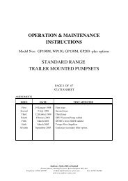
Model No. SY3871032<br />
<strong>GP</strong><strong>80</strong> DIESEL DRIVEN<br />
(2-wheel &electric skid)<br />
PAGE 1 OF 58<br />
STATUS SHEET<br />
AMENDMENTS<br />
ISSUE DATE TEXT AFFECTED<br />
First<br />
Second<br />
Third<br />
Fourth<br />
7 November1997<br />
06 June 1998<br />
February 2000<br />
November 2007<br />
First issue<br />
Second issue<br />
Safety Precautions.<br />
Company Address, Safety Precautions, Front Cover.<br />
<strong>Andrews</strong> <strong>Sykes</strong> Hire Limited<br />
Premier House, Darlington Street, Wolverhampton WV1 4JJ<br />
Telephone: 01902 328700 Fax:01902 42246<br />
E-mail: info@andrews-sykes.com webb: www.andrews-sykes.com<br />
<strong>Sykes</strong> Pumps<br />
Premier House, Darlington Street, Wolverhampton WV1 4JJ<br />
Telephone: 01902 328700 Fax:01902 42246<br />
E-mail: enquiries@sykes-pumps.com Web: www.sykes-pumps.com
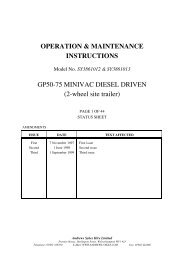
<strong>Sykes</strong> Pumps Ref. No. SY3871032 Issue Status:3<br />
OPERATION& MAINTENANCE INSTRUCTIONS Page 2 of 59<br />
<strong>GP</strong><strong>80</strong> DIESEL DRIVEN (2-WHEEL SITE TRAILER) Issued :Feb 2000<br />
1 CONTENTS<br />
1 CONTENTS 2<br />
1.1 List of Illustrations 4<br />
1.2 List of Tables 4<br />
2 FOREWORD 5<br />
3 SERVICING AND REPAIR INFORMATION 6<br />
3.1 Contacting your local <strong>Sykes</strong> depot 6<br />
3.2 Ordering spares 6<br />
4 SAFETY PRECAUTIONS 7<br />
4.1 Warnings and Cautions 7<br />
4.2 Training 7<br />
4.3 Representative Noise Levels 8<br />
4.4 Modifications 9<br />
4.5 Personal Protective Equipment 9<br />
5 DESCRIPTION OF EQUIPMENT 10<br />
5.1 General description 10<br />
5.2 Technical description 10<br />
5.2.1 Overview 10<br />
5.2.2 Main pump 13<br />
5.2.3 Vacuum Pump 13<br />
5.2.4 Engine, drives and fuel system 14<br />
5.2.5 Weights 14<br />
5.2.6 Chassis 15<br />
5.3 Product identification 15<br />
6 HANDLING AND OPERATION 16<br />
6.1 Lifting and transportation 16<br />
6.2 Trailer routine checks 16<br />
6.3 Siting and preparation for pumping 16<br />
6.4 Controls and connection points 17<br />
6.4.1 Main control panel 17<br />
6.5 Operating instructions 17
<strong>Sykes</strong> Pumps Ref. No. SY3871032 Issue Status:3<br />
OPERATION& MAINTENANCE INSTRUCTIONS Page 3 of 59<br />
<strong>GP</strong><strong>80</strong> DIESEL DRIVEN (2-WHEEL SITE TRAILER) Issued :Feb 2000<br />
6.5.1 General precautions 17<br />
6.5.2 Starting up 18<br />
6.5.3 Shutting down / Storage 19<br />
6.6 Testing 20<br />
6.7 Fault diagnosis 20<br />
6.7.1 Engine 20<br />
6.7.2 Pump performance fault diagnosis 21<br />
6.7.3 Priming system fault diagnosis 22<br />
7 MAINTENANCE 23<br />
7.1 Tools required 23<br />
7.2 Maintenance schedule 23<br />
7.3 General instructions and precautions 24<br />
7.3.1 Removal of engine and pump for major service 24<br />
7.4 Engine and fuel system 24<br />
7.4.1 General 24<br />
7.4.2 Cleaning the fuel tank 24<br />
7.5 Vacuum pump drive belt 24<br />
7.5.1 Adjusting belt tension - See on page 25<br />
7.5.2 Renewing the belt 25<br />
7.5.3 Cleaning and Replacement of Vacuum Pump Lubrication Oil 25<br />
7.6 Priming tank surge control valve and air valve 26<br />
7.7 Vacuum pump 26<br />
7.7.1 Removing the vacuum pump 26<br />
7.7.2 Service Instructions for Rotary Vacuum Pump 27<br />
7.7.3 Refitting vacuum pump 28<br />
7.8 Non-return valve 29<br />
7.9 Main pump impeller 29<br />
7.10 Removing and refitting pump pressure seal 30<br />
7.11 Main pump pressure seal 30<br />
7.11.1 Renewing the pump pressure seal packing 30<br />
7.11.2 Refitting pump pressure seal 30<br />
7.12 Fitting the impeller - Reference , page . 31<br />
7.13 Replacing the Priming tank, Sump Tee and Wear Plate 31<br />
8 SPARE PARTS 32<br />
8.1 Introduction 32<br />
8.2 Ordering Spares 32
<strong>Sykes</strong> Pumps Ref. No. SY3871032 Issue Status:3<br />
OPERATION& MAINTENANCE INSTRUCTIONS Page 4 of 59<br />
<strong>GP</strong><strong>80</strong> DIESEL DRIVEN (2-WHEEL SITE TRAILER) Issued :Feb 2000<br />
8.3 Spare Parts Listing 32<br />
9 APPENDICES 59<br />
9.1 Associated Publications 59<br />
1.1 List of Illustrations<br />
Figure 1 Main components 11<br />
Figure 2 Schematic drawing of the pumpset system 12<br />
Figure 3 Main Control Panel 17<br />
Figure 4 Pump fault diagnosis flowchart 21<br />
Figure 5 Priming fault diagnosis flowchart 22<br />
Figure 6 Drive Belt Arrangement 25<br />
Figure 7 Priming tank air and surge control valves 26<br />
Figure 8 Non-return Valve 29<br />
Figure 9 Miscellaneous Parts 34<br />
Figure 10 Vacuum Pump 36<br />
Figure 11 Vacuum Pump Drive Assembly 38<br />
Figure 12 Lube Bottle Arrangement 40<br />
Figure 13 Main Pump Impeller and Wear Plates 42<br />
Figure 14 Priming Tank Assembly 44<br />
Figure 15 Non-Return Valve Assy 46<br />
Figure 16 Sump & Tee 48<br />
Figure 17 Two Wheel Site Trailer Assembly (Diesel Engine) 50<br />
Figure 18 Two Wheel High Speed Trailer Assembly 52<br />
Figure 19 General Arrangement - Electric Motor Option 54<br />
Figure 20 Vacuum Pump Drive Assembly-Electric Motor Option 56<br />
Figure 21 Electric Motor Pump End 58<br />
1.2 List of Tables<br />
Table 1 Representative Noise Levels 8<br />
Table 2 Main pump technical data 13<br />
Table 3 Vacuum system technical data 13<br />
Table 4 Engine and fuel system technical data 14<br />
Table 5 Approximate component and combined weights 14<br />
Table 6 Chassis technical data 15
<strong>Sykes</strong> Pumps Ref. No. SY3871032 Issue Status:3<br />
OPERATION& MAINTENANCE INSTRUCTIONS Page 5 of 59<br />
<strong>GP</strong><strong>80</strong> DIESEL DRIVEN (2-WHEEL SITE TRAILER) Issued :Feb 2000<br />
2 FOREWORD<br />
This manual covers the <strong>Andrews</strong> <strong>Sykes</strong> <strong>GP</strong><strong>80</strong> (2 WHEEL SITE TRAILER, 2 WHEEL<br />
HIGH SPEED TRAILER and ELECTRIC MOTOR OPTION) pump. It is written for<br />
operators and maintenance personnel and provides the information needed for safe and<br />
efficient siting, use, testing, routine maintenance and repairs.<br />
Manuals provided are an essential part of the relevant equipment. They should be kept<br />
for the life of the equipment and passed on to any subsequent purchaser. Any<br />
amendment issued by <strong>Andrews</strong> <strong>Sykes</strong> Hire Limited should be promptly incorporated<br />
into this manual.<br />
Information contained in this manual is correct at the date of publication. As<br />
improvements are continually being made, <strong>Andrews</strong> <strong>Sykes</strong> Hire Limited reserve the<br />
right to make alterations without giving prior notice.<br />
© 1998 <strong>Andrews</strong> <strong>Sykes</strong> Hire Limited. The contents of this manual are copyright and<br />
must not be reproduced without prior permission of <strong>Andrews</strong> <strong>Sykes</strong> Hire Limited.<br />
Product names referenced in this manual are registered trade marks of the original<br />
equipment manufacturers.<br />
HEALTH & SAFETY STATEMENT<br />
DO TAKE TIME TO ENSURE THAT YOUR SAFETY AND THAT OF OTHERS IS NOT PUT AT RISK.<br />
FAILURE TO OBSERVE PRECAUTIONS, BOTH ELEMENTARY AND THOSE EXPLICIT IN THIS<br />
MANUAL, MAY RESULT IN PERSONAL INJURY AND/OR DAMAGE TO EQUIPMENT. THE<br />
SAFETY INFORMATION ON PAGE 7 IS INTENDED TO MAKE YOU AWARE OF HAZARDS AND<br />
PRECAUTIONS AND TO ENCOURAGE A SAFETY-CONSCIOUS APPROACH TO OPERATING AND<br />
CARRYING OUT MAINTENANCE WORK ON THIS EQUIPMENT.
<strong>Sykes</strong> Pumps Ref. No. SY3871032 Issue Status:3<br />
OPERATION& MAINTENANCE INSTRUCTIONS Page 6 of 59<br />
<strong>GP</strong><strong>80</strong> DIESEL DRIVEN (2-WHEEL SITE TRAILER) Issued :Feb 2000<br />
3 SERVICING AND REPAIR INFORMATION<br />
3.1 Contacting your local <strong>Sykes</strong> depot<br />
For any enquiry regarding the use, servicing or repair of your <strong>Andrews</strong> <strong>Sykes</strong> pump,<br />
please contact your local <strong>Andrews</strong> <strong>Sykes</strong> Hire Ltd depot on (freefone) 0<strong>80</strong>0-211-611.<br />
Please provide the following information:<br />
(1) Machine model and chassis type<br />
(2) Model-Serial number of the machine<br />
(2) Approximate date of purchase<br />
(3) Details of enquiry, apparent fault(s), etc.<br />
Section 5.3, Product identification, page 14, describes how to identify models and where<br />
to locate the Model-Serial number.<br />
3.2 Ordering spares<br />
Section 8, Spare parts, page 32, explains how to order spare parts.
<strong>Sykes</strong> Pumps Ref. No. SY3871032 Issue Status:3<br />
OPERATION& MAINTENANCE INSTRUCTIONS Page 7 of 59<br />
<strong>GP</strong><strong>80</strong> DIESEL DRIVEN (2-WHEEL SITE TRAILER) Issued :Feb 2000<br />
4 SAFETY PRECAUTIONS<br />
4.1 Warnings and Cautions<br />
For the purpose of definition in this manual, a WARNING gives information which, if<br />
ignored, could cause serious injury to personnel. A CAUTION gives information which<br />
if ignored could cause serious damage to the machine or associated equipment. Also see<br />
Operating Instructions, General Precautions in Section 6.5.1 on page 17.<br />
WARNING<br />
Warning notices are boxed and highlighted in the style of this paragraph.<br />
CAUTION<br />
Cautionary notices are boxed and highlighted in the style of this paragraph.<br />
4.2 Training<br />
It is strongly recommended that all operators, other personnel working on or near the<br />
pump, and any site visitors, are made fully aware of the potential dangers of this rotating<br />
equipment. If in ANY doubt please contact <strong>Andrews</strong> <strong>Sykes</strong> Limited for advice.<br />
WARNINGS<br />
FOR YOUR OWN PERSONAL SAFETY READ AND TAKE NOTE OF THE FOLLOWING:<br />
Hazardous areas - All moving parts, including drive belts, are dangerous<br />
and are guarded to prevent intrusion during operation.<br />
Pump intake and discharge ports are also dangerous<br />
when open. Do not insert hands or other objects into<br />
the ports when the pump is operating.<br />
Lifting and transport - Read and follow the instructions on page 16. In<br />
particular, always lift using the lifting points provided<br />
and ensure that any lifting equipment is of adequate<br />
load-carrying capacity and possesses a valid test<br />
certificate.
<strong>Sykes</strong> Pumps Ref. No. SY3871032 Issue Status:3<br />
OPERATION& MAINTENANCE INSTRUCTIONS Page 8 of 59<br />
<strong>GP</strong><strong>80</strong> DIESEL DRIVEN (2-WHEEL SITE TRAILER) Issued :Feb 2000<br />
Operating the pump - Replace all guarding removed for maintenance before<br />
starting the pump. Never operate without covers and<br />
guards in place.<br />
Never operate the pump without the correct protective<br />
clothing and equipment (PPE).<br />
Before attempting maintenance work on the pumpset,<br />
ensure that the engine is properly isolated. Refer to the<br />
manufacturer’s handbook for details.<br />
Note the general precautions on page16 and ensure that<br />
you are familiar with the controls before operating the<br />
pump. Read and follow the instructions on safe siting<br />
and operation on pages 16 to 19.<br />
Fault finding and pump<br />
maintenance<br />
- Follow a regular maintenance schedule as defined on<br />
page 23.<br />
4.3 Representative Noise Levels<br />
WARNING<br />
Please be awear noise levels during operation may exceed recommended<br />
exposure levels<br />
Table 1 Represenataive Noise Levels<br />
Pump Model Driver Speed<br />
RPM<br />
Sound<br />
Power<br />
Level<br />
Sound<br />
Pressure<br />
Level at 1m<br />
Sound<br />
Pressure<br />
Level at 7m<br />
<strong>GP</strong><strong>80</strong> Lister TR1 2000 106 98 81<br />
1<strong>80</strong>0 104 96 79<br />
1500 103 95 78
<strong>Sykes</strong> Pumps Ref. No. SY3871032 Issue Status:3<br />
OPERATION& MAINTENANCE INSTRUCTIONS Page 9 of 59<br />
<strong>GP</strong><strong>80</strong> DIESEL DRIVEN (2-WHEEL SITE TRAILER) Issued :Feb 2000<br />
4.4 Modifications<br />
Any unauthorised modification to the product may impinge upon the validity of the CE<br />
Compliance for the machine, the warranty of the product.and the safe working of the<br />
product.<br />
For any enquiry regarding the use , serviceing or repair of your <strong>Andrews</strong> <strong>Sykes</strong> Pump, please<br />
contact your local <strong>Andrews</strong> <strong>Sykes</strong> Hire Ltd service centre on (free phone) 0<strong>80</strong>0-211611<br />
4.5 Personal Protective Equipment<br />
The following PPE is recommended when installing and operating the pumpset.<br />
Hand Protection as a result of general handling of the pumpset and hoses, along with protection<br />
from the liquid being pumped.<br />
Protective footwear due to the general handling of the pumpset and hoses.<br />
Protective clothing due to the handling of the pumpset and hoses, along with protection from the<br />
liquid being pumped.<br />
Eye protection during installation and operation due to splashes from the liquid being pumped.<br />
Ear protection during operation of pumpset.<br />
WARNING<br />
It is recommended a full RISK ASSESMENT is carried out prior to commencement of<br />
any Maintenance, Installation or Operation of Pumpset<br />
L<br />
Note: Please be awear of any invironmental issues associated with the Maintenance,<br />
Installation and operation of the Pumpset, please read general precuations on page 17.
<strong>Sykes</strong> Pumps Ref. No. SY3871032 Issue Status:3<br />
OPERATION& MAINTENANCE INSTRUCTIONS Page 10 of 59<br />
<strong>GP</strong><strong>80</strong> DIESEL DRIVEN (2-WHEEL SITE TRAILER) Issued :Feb 2000<br />
5 DESCRIPTION OF EQUIPMENT<br />
5.1 General description<br />
The <strong>GP</strong><strong>80</strong> is a general purpose, self priming, free standing site pump. The pumps can be used<br />
in a range of environmental conditions, including tropical temperatures.<br />
Each pump is capable of passing solids up to the specified maximum diameter for the size of<br />
machine (see Table 2, page13), provided the solids are in suspension; a typical example<br />
being ditch water containing soil and rock particles. Slurries may also be pumped, if<br />
concentration of solid matter is not too high. The pumps can also handle abrasive materials at<br />
the expense of higher wear rate. (For advice on the suitability of your pump for specific<br />
applications contact your local <strong>Sykes</strong> depot; see Section 3.1, page 6.)<br />
The <strong>GP</strong><strong>80</strong> pump is normally powered by a diesel engine with electric start. It has a two<br />
wheeled chassis which is suitable for towing on site.<br />
5.2 Technical description<br />
5.2.1 Overview<br />
This section identifies the main components of the standard pump and provides general<br />
technical and performance data. It does not cover any special options or modifications made<br />
to suit customer requirements.<br />
L NOTE: Tolerances are given in Maintenance, Section 7 page 23.<br />
Figure 1, page 11, shows the general arrangement and the overall dimensions of the pump<br />
set.<br />
L<br />
NOTE: By adjusting the ‘surge control valve’, when the pump is fully primed, the operator<br />
can prevent continual air valve cycling -an effect referred to as ‘snoring’ (see Figure 7 on<br />
page 26.)
<strong>Sykes</strong> Pumps Ref. No. SY3871032 Issue Status:3<br />
OPERATION& MAINTENANCE INSTRUCTIONS Page 11 of 59<br />
<strong>GP</strong><strong>80</strong> DIESEL DRIVEN (2-WHEEL SITE TRAILER) Issued :Feb 2000<br />
Fig 1 Main components
<strong>Sykes</strong> Pumps Ref. No. SY3871032 Issue Status:3<br />
OPERATION& MAINTENANCE INSTRUCTIONS Page 12 of 59<br />
<strong>GP</strong><strong>80</strong> DIESEL DRIVEN (2-WHEEL SITE TRAILER) Issued :Feb 2000<br />
Figure 2 illustrates, schematically, the pumpset's principle of operation.<br />
PRIMING PUMP<br />
LUBE<br />
BOTTLE<br />
EXHAUST TO<br />
ATMOSPHERE<br />
OIL DRIP FEED<br />
FILTERED AIR<br />
INTAKE FROM<br />
ATMOSPHERE<br />
MAIN DISCHARGE<br />
DRIVE<br />
NON RETURN<br />
VALVE<br />
DRIVE<br />
PRIMING TANK<br />
MAIN PUMP<br />
ENGINE<br />
SOURCE<br />
MAIN FLOW<br />
VACUUM FLOW<br />
VACUUM DRAWN LUBRICATING OIL<br />
EXHAUST FLOW<br />
Figure 2 Schematic drawing of the pumpset system
<strong>Sykes</strong> Pumps Ref. No. SY3871032 Issue Status:3<br />
OPERATION& MAINTENANCE INSTRUCTIONS Page 13 of 59<br />
<strong>GP</strong><strong>80</strong> DIESEL DRIVEN (2-WHEEL SITE TRAILER) Issued :Feb 2000<br />
5.2.2 Main pump<br />
Figure 13 shows the main pump in detail page 42.<br />
Table 2 Main pump technical data<br />
PARAMETER<br />
<strong>GP</strong><strong>80</strong><br />
Standard pump body (volute) material<br />
Volute size<br />
Cast iron<br />
<strong>80</strong>mm<br />
Intake and discharge ports 4"BST’D’<br />
Solids handling capability (maximum diameter)<br />
40mm<br />
Maximum lift (theoretical) 9.75m<br />
Maximum discharge head<br />
Maximum flow<br />
Pump bearing grease<br />
Nominal speed<br />
20m<br />
90m³/hr<br />
Shell Alvania EP2 or equivalent<br />
2000 rpm<br />
5.2.3 Vacuum Pump<br />
Figure 10 shows an exploded view of the vacuum pump. Figure 11 on page 36<br />
shows it assembled in the vacum pump drive assembly.<br />
Table 3 Vacuum system technical data<br />
COMPONENT/PARAMETER<br />
Vacuum pump<br />
Vacuum pump displacement<br />
Vacuum level<br />
<strong>GP</strong><strong>80</strong><br />
Utile vacuum pump<br />
0.012m³/s<br />
10m<br />
Lubricating oil 30 SAE viscosity below 30ºC<br />
10W30 SAE above 30ºC<br />
Nominal speed<br />
1<strong>80</strong>0 rpm
<strong>Sykes</strong> Pumps Ref. No. SY3871032 Issue Status:3<br />
OPERATION& MAINTENANCE INSTRUCTIONS Page 14 of 59<br />
<strong>GP</strong><strong>80</strong> DIESEL DRIVEN (2-WHEEL SITE TRAILER) Issued :Feb 2000<br />
5.2.4 Engine, drives and fuel system<br />
Table 4 Engine and fuel system technical data<br />
COMPONENT/PARAMETER SPECIFICATION COMMENTS<br />
Engine<br />
Main pump coupling<br />
Vacuum pump transmission<br />
Battery<br />
Fuel tank<br />
Approximate running time on full<br />
tank, at max load<br />
Nominal speed<br />
Lister TR1 air cooled<br />
single cylinder diesel<br />
engine<br />
d/c stub shaft<br />
Fenner v-belt and<br />
pulleys<br />
037 × 35 Ah<br />
35 litres<br />
16.5 hours<br />
2000 rpm<br />
Drives main and<br />
vacuum pumps<br />
5.2.5 Weights<br />
Table 4 provides approximate component weights for the Pumpset and its major<br />
components. The weights given are typical and may vary by ±20% for individual<br />
machines. Therefore, ensure that all lifting and towing equipment used have a safe<br />
working load of at least 120% of the relevant indicated weight.<br />
Table 5 Approximate component and combined weights<br />
COMPONENT<br />
WEIGHT (kg)<br />
Engine (dry) 142<br />
Main pump 160<br />
Main pump, priming tank, engine and stub shaft 325<br />
Priming tank 23<br />
Gross weight with full tank of fuel 435
<strong>Sykes</strong> Pumps Ref. No. SY3871032 Issue Status:3<br />
OPERATION& MAINTENANCE INSTRUCTIONS Page 15 of 59<br />
<strong>GP</strong><strong>80</strong> DIESEL DRIVEN (2-WHEEL SITE TRAILER) Issued :Feb 2000<br />
5.2.6 Chassis<br />
Table 6 Chassis technical data<br />
COMPONENT/PARAMETER<br />
General specification<br />
Maximum towing speed<br />
Tyres<br />
Wheel bearing grease<br />
Tow-hitch coupling<br />
Recommended lifting methods<br />
DETAILS/VALUE<br />
2 wheel site trailer<br />
10 kph<br />
Pneumatic rubber<br />
High melting point water repellent grease<br />
recommended<br />
Tow-bar with standard ø 20mm eye<br />
Crane, using the single lifting point.<br />
5.3 Product identification<br />
For your own security and to enable <strong>Andrews</strong> <strong>Sykes</strong> Hire Ltd to answer any enquiries<br />
and requests for service and spares, where not stated, record details of your pumpset<br />
in the table below.<br />
Model:<br />
DETAIL<br />
<strong>GP</strong><strong>80</strong><br />
CORRESPONDING<br />
INFORMATION<br />
Type of chassis:<br />
‘Model-Serial number’. Figure 1, page<br />
11 shows where on the pumpset these<br />
numbers are marked.<br />
2-Wheel Site Trailer<br />
Model number: SY3871032<br />
Serial number:<br />
Engine serial number. (See Associated<br />
Publications, page59.):<br />
Date of purchase:
<strong>Sykes</strong> Pumps Ref. No. SY3871032 Issue Status:3<br />
OPERATION& MAINTENANCE INSTRUCTIONS Page 16 of 59<br />
<strong>GP</strong><strong>80</strong> DIESEL DRIVEN (2-WHEEL SITE TRAILER) Issued :Feb 2000<br />
6 HANDLING AND OPERATION<br />
6.1 Lifting and transportation<br />
The pumpset is equipped with the single point lifting eye by which it can be lifted<br />
using a suitable chain. The site trailer MUST NOT be towed on the public highway.<br />
WARNINGS<br />
DO NOT attempt to lift pump with suction and discharge hoses in place.<br />
ALWAYS ensure that lifting gear are adequate for the weight being lifted (See Table 4.).<br />
6.2 Trailer routine checks<br />
Routine checks are essential for the safety of personnel and the maintenance of equipment<br />
condition.<br />
1. Check tyre and wheel retaining pin conditions. Renew if heavily damaged.<br />
2. Verify that the tow-hitch is sound and that all that the trailer chassis is in good<br />
condition.<br />
3. Grease wheel bearings and all trailer moving joints.<br />
6.3 Siting and preparation for pumping<br />
If you wish to test pump operation before use, refer to Testing, page 19.<br />
1. Place the pumpset on a firm, level area of ground, as close as practical to the source<br />
of liquid.<br />
CAUTION<br />
DO NOT place the unit on soft ground into which it could sink.<br />
2. Connect the hoses to the intake and discharge flanges (see Figure 1, page 11).<br />
L<br />
USE all the bolt holes provided on the flanges. DO NOT use a collapsible hose on the suction<br />
side, and make sure that the strainer is in place on the suction side.<br />
3. Submerge the end of the suction hose.<br />
4. Place the end of the discharge hose in a suitable outlet.<br />
CAUTION<br />
DO NOT put any stress on hoses. Lay them so as to avoid forming sharp kinks and<br />
protect them where they come in contact with abrasive surfaces.
<strong>Sykes</strong> Pumps Ref. No. SY3871032 Issue Status:3<br />
OPERATION& MAINTENANCE INSTRUCTIONS Page 17 of 59<br />
<strong>GP</strong><strong>80</strong> DIESEL DRIVEN (2-WHEEL SITE TRAILER) Issued :Feb 2000<br />
6.4 Controls and connection points<br />
6.4.1 Main control panel<br />
OFF<br />
RUN PRE HEAT<br />
START<br />
Starting Switch<br />
Running Hours<br />
½<br />
0 0 0 0 0 0 h<br />
Figure 3 Main Control Panel<br />
6.5 Operating instructions<br />
6.5.1 General precautions<br />
WARNINGS<br />
DO NOT attempt to insert anything into the pump intake and discharge ports while the engine<br />
is running.<br />
Ensure the pumpset is stable and immobilised BEFORE starting the pump.<br />
BEWARE of fire risks. DO NOT place any flammable material near or around the engine or<br />
exhaust. Allow adequate ventilation.<br />
The engine, exhaust and coalescer become HOT during operation.<br />
ENSURE that any discharge into rivers or watercourses, or to soak away onto land, is<br />
environmentally acceptable.<br />
The pump body retains liquid which could be hazardous to health. Flush the pump with clean<br />
water BEFORE disconnecting the hoses or working on the pump.
<strong>Sykes</strong> Pumps Ref. No. SY3871032 Issue Status:3<br />
OPERATION& MAINTENANCE INSTRUCTIONS Page 18 of 59<br />
<strong>GP</strong><strong>80</strong> DIESEL DRIVEN (2-WHEEL SITE TRAILER) Issued :Feb 2000<br />
L<br />
NOTE: In the event of an emergency, STOP the engine IMMEDIATELY using the engine stop<br />
lever (see manufacturer’s handbook).<br />
NEVER use the pump without a strainer.<br />
CAUTIONS<br />
DO NOT pump, either liquids that may damage the pump, or dry material. If in doubt contact<br />
your local <strong>Andrews</strong> <strong>Sykes</strong> Hire Ltd depot for advice (see Section 3.1, page6).<br />
6.5.2 Starting up<br />
Follow this procedure before each engine start-up. Refer to Figure 3, page17, for details of<br />
the keyswitch.<br />
WARNINGS<br />
Make sure you are familiar with the engine manufacturer’s safety instructions BEFORE<br />
running the engine.<br />
CAUTION<br />
ALWAYS top up using oil of correct specification. See the manufacturer’s handbook for<br />
details of engine oil, and Table 2, page 12, for details of vacuum pump oil.<br />
1. Check and top up, if necessary;<br />
i the engine fuel, oil and radiator water levels;<br />
ii the oil level in the lubrication bottle feeding the vacuum pump;<br />
iii fuel tank.<br />
2. Ensure that all drain taps are closed.<br />
3. Screw in fully the priming tank surge control valve, to allow the system to prime.<br />
4. Submerge the intake hose in the source.<br />
5. Turn the key clockwise to the START position and release as soon as the engine starts.<br />
If the engine fails to start within 30 seconds, release the key and attempt to restart after<br />
allowing time for all moving parts to come to rest.<br />
(The pump should prime automatically. In case of start-up failure, consult, Section 6.7 , Fault<br />
diagnosis on page20.)<br />
6. When the pump is fully primed, re-adjust the surge control valve, as necessary, to avoid<br />
excessive 'snoring' -see note on page 10.
<strong>Sykes</strong> Pumps Ref. No. SY3871032 Issue Status:3<br />
OPERATION& MAINTENANCE INSTRUCTIONS Page 19 of 59<br />
<strong>GP</strong><strong>80</strong> DIESEL DRIVEN (2-WHEEL SITE TRAILER) Issued :Feb 2000<br />
6.5.3 Shutting down / Storage<br />
L TO STOP: Turn the engine lever to the OFF position and push in fully the surge control<br />
valve knob to release the vacuum and empty the the priming tank and the intake<br />
hose. Turn key to OFF position.<br />
CAUTION<br />
ALWAYS drain the pump; before removing it, or if it is being left unused for a while -especially<br />
in cold weather.<br />
The procedure is as stated below.<br />
1. Flush the pump with clean water.<br />
2. Drain water from the following, through the drain taps or plugs provided;<br />
i<br />
ii<br />
iii<br />
iv<br />
the main pump;<br />
the priming tank;<br />
the non-return valve; and,<br />
the coalescer<br />
3. Follow the engine manufacturer's instructions relating to engine being left unused for a<br />
period of time.<br />
If the pump is to be moved to a new site, disconnect the hoses and follow the instructions in<br />
Section 6.1, Lifting and transportation, page16.<br />
To maintain the body parts in good condition, it is strongly recommended that the trailer is steam<br />
or spray cleaned regularly to remove dirt, mud and grit.<br />
When not in use store the trailer under cover in a dry environment, where practicable.<br />
CAUTION<br />
NEVER leave water in the pumps or hoses if there is any risk of it freezing.<br />
6.6 Testing<br />
To test correct operation of the pumpset before its first service, or whenever required, follow the<br />
procedure described below.<br />
1. Immobilise and secure the pumpset, at the test site.
<strong>Sykes</strong> Pumps Ref. No. SY3871032 Issue Status:3<br />
OPERATION& MAINTENANCE INSTRUCTIONS Page 20 of 59<br />
<strong>GP</strong><strong>80</strong> DIESEL DRIVEN (2-WHEEL SITE TRAILER) Issued :Feb 2000<br />
2. Start the engine as described in Section 6.5.2, page 18, but leave the surge control valve<br />
fully screwed in throughout the test.<br />
3. Place a 'cone tester' (or an alternative test gauge) in the inlet flange and check that the<br />
vacuum reading is sufficient for the intended lift plus the pipework losses. If the vacuum<br />
reading is unsatisfactory or the pump fails to prime consult Fault diagnosis, Section 6.7,<br />
page 20.<br />
4. Stop the engine. (See manufacturer’s handbook)<br />
6.7 Fault diagnosis<br />
6.7.1 Engine<br />
The engine has no engine shutdown safety systems.<br />
See manufacturer’s handbook for further details on operation.
<strong>Sykes</strong> Pumps Ref. No. SY3871032 Issue Status:3<br />
OPERATION& MAINTENANCE INSTRUCTIONS Page 21 of 59<br />
<strong>GP</strong><strong>80</strong> DIESEL DRIVEN (2-WHEEL SITE TRAILER) Issued :Feb 2000<br />
6.7.2 Pump performance fault diagnosis<br />
POOR PUMP PERFORMANCE<br />
When coupled to short discharge pipe<br />
When pumping a great<br />
distance or head<br />
i) Is strainer blocked ?<br />
ii) Has suction hose collapsed ?<br />
iii) Are suction hose seals missing ?<br />
Yes<br />
Yes<br />
Is engine<br />
speed low ?<br />
No<br />
No<br />
Take pump vacuum reading<br />
Check the discharge line<br />
Is it low<br />
compared with suction lift<br />
of application ?<br />
No<br />
Adjust or rectify as<br />
apropriate<br />
i) Is it too long ?<br />
ii) Has it too many bends ?<br />
iii) Does it rise a great height ?<br />
iv) A combination of the above ?<br />
v) Has it collapsed or crushed ?<br />
No<br />
Is<br />
engine speed low ?<br />
Yes<br />
Yes<br />
Does the<br />
pump discharge<br />
into a pipeline under<br />
pressure ?<br />
No<br />
No<br />
Yes<br />
Is<br />
non-return valve<br />
blocked ?<br />
Yes<br />
Verify that pump is suitable for<br />
your application. Consult your<br />
local Andrew <strong>Sykes</strong> depot.<br />
Yes<br />
No<br />
STOP engine<br />
Yes<br />
Yes<br />
Is the<br />
pump suitable ?<br />
STOP engine<br />
Is impeller<br />
blocked, heavily<br />
worn or wear plates need<br />
adjusting ?<br />
See 'Poor pump<br />
performance' flow chart<br />
No<br />
Contact your nearest <strong>Andrews</strong> <strong>Sykes</strong> Hire Depot for advice<br />
No<br />
Figure 4 Pump fault diagnosis flowchart
<strong>Sykes</strong> Pumps Ref. No. SY3871032 Issue Status:3<br />
OPERATION& MAINTENANCE INSTRUCTIONS Page 22 of 59<br />
<strong>GP</strong><strong>80</strong> DIESEL DRIVEN (2-WHEEL SITE TRAILER) Issued :Feb 2000<br />
6.7.3 Priming system fault diagnosis<br />
PUMP FAILS TO PRIME<br />
Check main pump vacuum reading<br />
No<br />
Is reading good ?<br />
Yes<br />
Check vacuum pump inlet reading<br />
Is reading good ?<br />
Yes<br />
Blank off main pump suction and<br />
delivery. Check valve gear, gland<br />
packing and joints for leaks.<br />
Is there a<br />
leak ?<br />
Yes<br />
Check vertical distance between<br />
main pump inlet to the surface of<br />
source.<br />
No<br />
No<br />
Check non return<br />
valve<br />
i) Is drive belt broken ?<br />
ii) Is lub. oil failing to<br />
reach vacuum pump ?<br />
Is it<br />
blocked or not<br />
seating correctly<br />
?<br />
Yes<br />
No<br />
Drain water from coalescer<br />
sump and top it up with oil,<br />
if necessary.<br />
Yes<br />
No<br />
Check vacuum pump<br />
air filter.<br />
Is it<br />
clogged ?<br />
Yes<br />
Is<br />
it more than 30 ft<br />
(9.2m) ?<br />
No<br />
i) Is strainer blocked ?<br />
Is vacuum pump oil<br />
pick-up pipe leaking ?<br />
Yes<br />
No<br />
Adjust or rectify<br />
(as apropriate).<br />
Resume operation.<br />
Yes<br />
ii)<br />
Has suction hose<br />
collapsed ?<br />
iii) Are suction hose seals<br />
missing ?<br />
No<br />
Contact your local <strong>Andrews</strong> <strong>Sykes</strong> Hire Depot for<br />
advice<br />
No<br />
Figure 5 Priming fault diagnosis flowchart
<strong>Sykes</strong> Pumps Ref. No. SY3871032 Issue Status:3<br />
OPERATION& MAINTENANCE INSTRUCTIONS Page 23 of 59<br />
<strong>GP</strong><strong>80</strong> DIESEL DRIVEN (2-WHEEL SITE TRAILER) Issued :Feb 2000<br />
7 MAINTENANCE<br />
7.1 Tools required<br />
1. A fitter’s standard toolkit.<br />
7.2 Maintenance schedule<br />
The following schedule provides a guide for maintaining the pump.<br />
The actual hours of operation between maintenance will depend on the operating conditions. For<br />
full details of engine maintenance, refer to the manufacturer’s handbook.<br />
Maintenance description<br />
Refer<br />
to<br />
Section<br />
Running hours<br />
Daily 125 250 500 2000 6000<br />
Vacuum pump and priming system:<br />
Check tension and condition of<br />
vacuum pump drive belt<br />
Check priming tank valves and<br />
clean or renew air filter<br />
7.5 ×<br />
7.6 ×<br />
Renew vacuum pump drive belt 7.5 ×<br />
Check non-return valve ball is<br />
sealing on seat<br />
Dismantle and clean priming<br />
tank, valves and pipes<br />
Check performance of vacuum<br />
pump and overhaul as necessary<br />
7.8 ×<br />
7.6 ×<br />
7.7 ×<br />
Main pump:<br />
Check impeller and wear plates<br />
for wear and renew or adjust as<br />
required.<br />
Renew pump pressure seal gland<br />
packing<br />
7.9 ×<br />
7.11 ×
<strong>Sykes</strong> Pumps Ref. No. SY3871032 Issue Status:3<br />
OPERATION& MAINTENANCE INSTRUCTIONS Page 24 of 59<br />
<strong>GP</strong><strong>80</strong> DIESEL DRIVEN (2-WHEEL SITE TRAILER) Issued :Feb 2000<br />
7.3 General instructions and precautions<br />
7.3.1 Removal of engine and pump for major service<br />
See Figure 9, page 34, for details of lifting points, securing bolts etc.<br />
WARNINGS<br />
Chock and stabilise the chassis BEFORE commencing work.<br />
CAUTIONS<br />
Drain main pump volute and priming tank.<br />
ALWAYS remove major component to clean for workshop conditions, for overhaul.<br />
1. Disconnect the wiring loom from the key switch.<br />
2. Disconnect and remove the battery.<br />
3. Disconnect the fuel hoses from the engine.<br />
4. Remove all guarding.<br />
5. Disconnect the engine from its mounts and the pump matching piece.<br />
6. Remove priming tank, sump tee assembly and front wear plate from volute.<br />
7. Remove impeller and pump mounting bolts, withdraw pump from stub shaft.<br />
8. Lift engine by its lifting points (Lifting gear will be required).<br />
7.4 Engine and fuel system<br />
7.4.1 General<br />
Consult original manufacturer’s handbook for engine maintenance instructions.<br />
7.4.2 Cleaning the fuel tank<br />
1. Remove its drain plug and drain the fuel tank.<br />
2. Remove all traces of dirt, debris and fuel by steam cleaning.<br />
3. Drain the tank of all water and ensure that its inside is dry.<br />
4. Replace the drain plug.<br />
7.5 Vacuum pump drive belt<br />
The vacuum pump drive arrangement is illustrated in Figure 6 page 25.
<strong>Sykes</strong> Pumps Ref. No. SY3871032 Issue Status:3<br />
OPERATION& MAINTENANCE INSTRUCTIONS Page 25 of 59<br />
<strong>GP</strong><strong>80</strong> DIESEL DRIVEN (2-WHEEL SITE TRAILER) Issued :Feb 2000<br />
7.5.1 Adjusting belt tension - See Figure 11 on page38.<br />
Figure 6 Drive Belt Arrangement<br />
1. Loosen the vacuum pump mounting bracket screws.<br />
2. Re-position the vacuum pump mounting bracket to adjust the tension of the belt. (At the<br />
correct tension a force of 3.5lbs (1.6kg) is needed to deflect the belt 4mm at the midpoint<br />
between the pulleys.)<br />
3. When the vacuum pump is in the correct position, tighten the vacuum pump mounting<br />
bracket locking screws (B03, B04, B05).<br />
7.5.2 Renewing the belt<br />
1. Remove guarding.<br />
2. Loosen the vacuum pump mounting bracket screws and move the assembly mounting<br />
plate towards the engine shaft to slacken the belt.<br />
3. Slide the belt off the pulleys.<br />
4. Fit a new belt and adjust the tension as described in the Section 7.5.1.page 24.<br />
5. Replace guarding.<br />
7.5.3 Cleaning and Replacement of Vacuum Pump Lubrication Oil<br />
1. Remove all retaining clips on oil feed line and disconnect.<br />
2. Remove lubrication bottle from its securing bracket.<br />
3. Drain oil from both and clean in petrol or similar spirit.<br />
4. Reconnect and replace with all clips and refill with new oil (specification as Table 2 on<br />
page 13). See Figure 12, page 40.
<strong>Sykes</strong> Pumps Ref. No. SY3871032 Issue Status:3<br />
OPERATION& MAINTENANCE INSTRUCTIONS Page 26 of 59<br />
<strong>GP</strong><strong>80</strong> DIESEL DRIVEN (2-WHEEL SITE TRAILER) Issued :Feb 2000<br />
7.6 Priming tank surge control valve and air valve<br />
Regularly check<br />
for wear areas<br />
indicated.<br />
Air valve<br />
Surge control valve<br />
Figure 7 Priming tank air and surge control valves<br />
Figure 7 shows the air and surge control valve assemblies , indicating areas that should be<br />
checked for wear and damage. To access the valves or for cleaning out, remove the priming tank<br />
top complete with valve gear. See Figure 14, page 44. Renew parts, as necessary and grease<br />
valve seats to prevent seizure.<br />
7.7 Vacuum pump<br />
7.7.1 Removing the vacuum pump<br />
See Figure 11, page 38.<br />
WARNING<br />
Lifting equipment may be required to remove the 18 ft 3 /min vacuum pump, where fitted. Check<br />
Technical Specification, section 5.2. page 10.<br />
1. Remove guarding.<br />
2. Disconnect hoses from the vacuum pump.<br />
3. Using a suitable spanner, disconnect the oil feed pipe at the vacuum pump and withdraw<br />
the oil feed pipe.
<strong>Sykes</strong> Pumps Ref. No. SY3871032 Issue Status:3<br />
OPERATION& MAINTENANCE INSTRUCTIONS Page 27 of 59<br />
<strong>GP</strong><strong>80</strong> DIESEL DRIVEN (2-WHEEL SITE TRAILER) Issued :Feb 2000<br />
4. Loosen the vacuum pump mounting locking screws.<br />
5. Move vacuum pump mounting plate to allow the belt to slip over the vacuum pump<br />
pulley.<br />
6. Remove the two vacuum pump holding nuts.<br />
7. Remove the vacuum pump and pulley.<br />
7.7.2 Service Instructions for Rotary Vacuum Pump<br />
Rererence Figure 10, page 36.<br />
1. Installation<br />
When the machine is not required for immediate use the inlet and outlet must be kept<br />
covered, otherwise entry of foreign matter through the ports could cause serious damage.<br />
Connecting pipework on the intake side of the machine must be thoroughly cleaned to<br />
remove internal rust and scale. Use PTFE tape for making joints since surplus from<br />
jointing compounds will damage the blades if drawn into the machine. It is essential to<br />
fit a filter on the intake of vacuum pumps to prevent pipe scale, oil, water, dust and other<br />
harmful matter from being drawn in.<br />
2. Checks before use<br />
Before running the machine for the first time after installation or maintenance, make the<br />
following checks:<br />
1. Check that the machine is free by turning the shaft by hand through a few<br />
revolutions.<br />
2. Check that the direction of rotation is anti-clockwise when viewed from the<br />
drive shaft.<br />
3. The pump speed must not exceed 1<strong>80</strong>0 rpm.<br />
4. Ensure that there is an adequate supply of oil available in the oil tank or bottle.<br />
Use the following oil or equivalent - Shell Rimula X Oil 20/20W.<br />
3. Operation Instructions<br />
Regularly inspect any filters fitted in the intake pipeline. Clean the elements and renew<br />
when necessary. Failure to carry out this procedure will result in loss of performance<br />
and overheating. Check the blades for wear every 2500 running hours or if loss of<br />
performance occurs. Regrease both bearings every 1000 working hours, giving 1 stroke<br />
only with the grease gun, using one of the following greases:-<br />
Shell Darina Grease R2<br />
Shell Darina Grease R<br />
or equivalent.<br />
4. To inspect and change blades
<strong>Sykes</strong> Pumps Ref. No. SY3871032 Issue Status:3<br />
OPERATION& MAINTENANCE INSTRUCTIONS Page 28 of 59<br />
<strong>GP</strong><strong>80</strong> DIESEL DRIVEN (2-WHEEL SITE TRAILER) Issued :Feb 2000<br />
Remove fancowl (V25), fan (V24) and circular guard (V31). Undo 4 screws (V18) and<br />
draw off rear coverplate (V03) complete with outer race of roller bearing (V12), seal<br />
bush (V13) and seal (V14). The blades (V08) may now be inspected and should be<br />
renewed if the blade tips have worn so as to reduce the depth to 21mm (13/16") or less.<br />
When fitting new sliding blades check that they fall freely from the rotor slots. Measure<br />
the thickness of gaskets (V19) positioned between the coverplate and cylinder (V01).<br />
5. To change bearings and seals<br />
Proceed as above for changing blades and then remove endcap (V05) from coverplate.<br />
The outer race of roller bearing, seal and seal bush can be tapped out from the<br />
coverplate. Now undo 4 screws (V18) at drive end and remove drive end coverplate<br />
(V02) complete with rotor and shaft assembly (V06 and V07). Once again measure the<br />
thickness of gaskets (V19) between coverplate and cylinder. Take off endcap (V04)<br />
circlip (V23) and bearing abutment washer (V09). Some machines have shims (V20)<br />
fitted between the endcap and face of bearing, and care must be taken not to lose or<br />
damage these. the purpose of these shims is to provide the correct clearance between<br />
coverplate and front face of rotor (V06). Continue to dismantle by pressing out shaft<br />
leaving the bearings (V11) seal bush (V13), seal (V14) and thrust washer (V21) in<br />
coverplate. These items can now be tapped out from the coverplate.<br />
6. To reassemble<br />
Reassemble in reverse order. When fitting the angular contact bearings (V11) these are<br />
assembled in the back-to-back position. When grease seals (V14) are replaced ensure<br />
that the tension spring faces the bearings. It is essential that all parts are perfectly clean<br />
before assembly. Re-build with gaskets having exactly the same thickness as the<br />
originals and ensure that any shims (V20) are assembled in the correct position. The<br />
gaskets and shims are essential to give the correct running clearances which are:-<br />
1. Between coverplate and rotor - drive end .05/.75mm (.002/.003")<br />
2. Between coverplate and rotor - rear end .15/.175mm (.006/.007")<br />
3. Between rotor and cylinder bore .75/.10mm (.003/.004").<br />
Ensure that the coverplate location dowels (V15) are replaced.<br />
Failure to follow the above instructions can cause seizure or loss of performance.<br />
When ordering spare parts always quote the machine serial number.<br />
7.7.3 Refitting vacuum pump<br />
See Figure 11, page 38.<br />
1. Put the vacuum pump in place on the mounting bracket (B06).<br />
2. Refit the belt over the vacuum pump pulley (B08).<br />
3. Fit and tighten the vacuum pump holding down fixings (B12, B13, B14).
<strong>Sykes</strong> Pumps Ref. No. SY3871032 Issue Status:3<br />
OPERATION& MAINTENANCE INSTRUCTIONS Page 29 of 59<br />
<strong>GP</strong><strong>80</strong> DIESEL DRIVEN (2-WHEEL SITE TRAILER) Issued :Feb 2000<br />
4. Adjust the belt tension by moving vacuum pump mounting bracket on its slotted holes<br />
and tighten the vacuum pump mounting bracket screws as explained in Section 7.5.1,<br />
page 24.<br />
5. Refit the vacuum and exhaust hoses to the vacuum pump, ensuring each is refitted in the<br />
same position from which it was removed. Check that the fittings are tight.<br />
6. Check that the oil feed pipe is clean. Refit the pipe and check that the fitting is tight.<br />
7. The Taper Lock® bush screws should be checked for tightness after the machine has<br />
been run under load for a short time.<br />
8. Refit the guarding.<br />
7.8 Non-return valve<br />
Figure 8 Non-return Valve<br />
1. Regularly check the non-return valve, Figure 8, for blockage and wear.<br />
2. For a thorough inspection;<br />
i<br />
ii<br />
iii<br />
disconnect the non-return valve from the volute and remove it;<br />
detach the valve seat, remove the ball and inspect both for wear and damage;<br />
re-fit or renew as appropriate.<br />
7.9 Main pump impeller<br />
To check the condition of the impeller and wear plates without removing the main pump:<br />
1. Drain the volute.<br />
2. Disconnect the intake hose and fittings.<br />
3. Disconnect the volute from the priming tank.
<strong>Sykes</strong> Pumps Ref. No. SY3871032 Issue Status:3<br />
OPERATION& MAINTENANCE INSTRUCTIONS Page 30 of 59<br />
<strong>GP</strong><strong>80</strong> DIESEL DRIVEN (2-WHEEL SITE TRAILER) Issued :Feb 2000<br />
4. Remove priming tank and sump tee by removing nuts and washers.<br />
5. Consult Figure 13 on page 42.<br />
6. Remove the impeller assembly by unscrewing in an anti-clockwise direction, looking at<br />
the impeller end and extract it from the volute casing. Check for wear.<br />
7. If the impeller blades are damaged, replace the entire impller assembly. If only the wear<br />
ring is worn, remove it and bond on a replacement using a suitable retainer.<br />
8. Check the packing for wear and renew if necessary, as detailed in section 7.11.1 page 30.<br />
9. Refit the impeller and subsequently sump tee and priming tank assembly in reverse of<br />
previous instructions.<br />
7.10 Removing and refitting pump pressure seal<br />
Reference Figure 13, page 42.<br />
1. After removal of the impeller as described in Section 7.11 (optional NRV), withdrawing<br />
item through front of volute.<br />
2. Remove the set screw and washers from underside of volute. (Items W21, W22 & W23)<br />
3. Remove 3/8" nut and washers from their studs and extract pump end assembly off engine<br />
and accompanying stub shaft (Items W32 & W33) & (Items W34 & W35).<br />
4. Remove end cap by removing set screws and washers. (Items 5,6&7)<br />
5. Remove packing holder, spring and gaitor respectively. Replace any worn components<br />
as required.<br />
7.11 Main pump pressure seal<br />
The main pump pressure seal is shown in Figure 13 on page 42.<br />
Renewal of the pump pressure seal packing can be undertaken during regular inspection of the<br />
impeller as explained in Section 7.9, and replaced as explained in Section 7.11.1.<br />
7.11.1 Renewing the pump pressure seal packing<br />
1. Cut a 270mm length of 1/2" square packing material.<br />
2. Place the packing in the holder, butting the two ends first and then pressing the rest of<br />
the packing into the holder. The total length of packing is greater that the circumference<br />
of the holder and must be forced into place. The packing will protrude slightly from the<br />
face of the holder on completion.<br />
7.11.2 Refitting pump pressure seal<br />
1. Replace spring and gaitor onto packing holder.<br />
2. Replace end cap (with newly fitted o-ring if required) and tighten all set screws evenly<br />
to position the pressure seal assembly in the matching piece.
<strong>Sykes</strong> Pumps Ref. No. SY3871032 Issue Status:3<br />
OPERATION& MAINTENANCE INSTRUCTIONS Page 31 of 59<br />
<strong>GP</strong><strong>80</strong> DIESEL DRIVEN (2-WHEEL SITE TRAILER) Issued :Feb 2000<br />
3. Replace pump volute and matching piece assembly back onto the engine bell housing<br />
using the studs, nuts and washers previously removed and tighten evenly, as reverse of<br />
the steps in section 7.9 parts 1, 2, 3 & 4. For impeller refitting refer to Section 7.12.<br />
7.12 Fitting the impeller - Reference Figure 13, page 42.<br />
1. Clean the threaded portion of the shaft and impeller using solvent. Grease threads. Fit<br />
impeller shims (W13&14) and screw the impeller into place, making sure it is fully<br />
locked.<br />
2. Prior to final assembly, coat the outer edges of the wear plates heavily with water pump<br />
grease to facilitate removal at a later date.<br />
7.13 Replacing the Priming tank, Sump Tee and Wear Plate<br />
Reference Figure 13, page 42.<br />
1. Fit priming tank (c/w wear plates etc.) with no shims, pinch bolts only.<br />
2. Measure gap between volute and priming tank faces.<br />
3. Remove tank and refit with appropriate number of shims (ie. gap measured + 0.5mm).<br />
4. Check the shaft turns freely.<br />
5. Ensure all nuts and screws are tight before restarting.
<strong>Sykes</strong> Pumps Ref. No. SY3871032 Issue Status:3<br />
OPERATION& MAINTENANCE INSTRUCTIONS Page 32 of 59<br />
<strong>GP</strong><strong>80</strong> DIESEL DRIVEN (2-WHEEL SITE TRAILER) Issued :Feb 2000<br />
8 SPARE PARTS<br />
8.1 Introduction<br />
If you require spare parts for your <strong>Andrews</strong> <strong>Sykes</strong> pump please contact your local Andrew <strong>Sykes</strong><br />
Hire Ltd depot, telephone (free phone) 0<strong>80</strong>0-211-611.<br />
CAUTION<br />
The use of any spares other than those supplied by <strong>Andrews</strong> <strong>Sykes</strong> Hire Ltd for the machine in<br />
question may cause DAMAGE to the machine and may INVALIDATE any EC Declaration given in<br />
respect of the equipment.<br />
8.2 Ordering Spares<br />
When ordering spare parts, please provide the following details:<br />
Please provide the following information:<br />
(1) Machine model and chassis type<br />
(2) Model-Serial number of the machine<br />
(3) Part number<br />
(4) Description of part<br />
(5) Quantity required<br />
See Product identification, page 15 for details of model naming and serial numbers.
<strong>Sykes</strong> Pumps Ref. No. SY3871032 Issue Status:3<br />
OPERATION& MAINTENANCE INSTRUCTIONS Page 33 of 59<br />
<strong>GP</strong><strong>80</strong> DIESEL DRIVEN (2-WHEEL SITE TRAILER) Issued :Feb 2000<br />
8.3 Spare Parts Listing<br />
Miscellaneous parts<br />
Ref. Description Part No. Ref. Description Part No.<br />
01 Battery Box SY387200 17 Washer SY9519512<br />
02 Cable SY3864065 18 Set Screw SY9519140<br />
03 Cable SY3872001 19 Joint SY5004121<br />
04 Lug Ring SY3864066 20 C.E. Badge Mark SY2994010<br />
05 Lug Ring SY3864067 21 Lifting Bracket SY3872006<br />
06 Battery SY7004404 22 Silencer Exhaust S9124<br />
07 Socket Screw SY9519509 23 Spacer Engine<br />
Exhaust<br />
SY3<strong>80</strong>4372<br />
08 Set Screw SY9519095 24 Fuel Inlet Hose SY3<strong>80</strong>4065<br />
09 Set Screw SY6664006 25 Fuel Leak Off /<br />
Return Hose<br />
SY9519518<br />
10 Washer SY9509678 26 Set Screw SY9519181<br />
11 Lister Engine SY7841007 27 Flat Washer SY9509684<br />
12 Eye Nut Lifting SY3874040 28 Spring Washer SY9509812<br />
13 Set Screw SY9519075 29 Screw Csk HD SY9519526<br />
14 Washer SY9019353 30 Bolt SY9509555<br />
15 Bolt SY9519504 31 Copper Washer SY9519529<br />
16 Washer SY9509860
<strong>Sykes</strong> Pumps Ref. No. SY3871032 Issue Status:3<br />
OPERATION& MAINTENANCE INSTRUCTIONS Page 34 of 59<br />
<strong>GP</strong><strong>80</strong> DIESEL DRIVEN (2-WHEEL SITE TRAILER) Issued :Feb 2000<br />
19<br />
12,21<br />
11,22,<br />
23<br />
24,25,30,31<br />
15,16<br />
20<br />
01 - 10,<br />
26,27,28,29<br />
13,14<br />
17,18<br />
Figure 9 Miscellaneous Parts
<strong>Sykes</strong> Pumps Ref. No. SY3871032 Issue Status:3<br />
OPERATION& MAINTENANCE INSTRUCTIONS Page 35 of 59<br />
<strong>GP</strong><strong>80</strong> DIESEL DRIVEN (2-WHEEL SITE TRAILER) Issued :Feb 2000<br />
Vacuum pump assembly -18cfm<br />
Part No. SY3874077<br />
Ref. Description Part No. Ref. Description Part No.<br />
V01 Cylinder S8416 V19 Gasket - Coverplate K1001<br />
V02 Coverplate -D.E. S<strong>80</strong>18/S<br />
P<br />
V20 Bearing Shim K1005<br />
V03 Coverplate -Rear S8426 V21 Thrust Washer B1100<br />
V04 End Cap - D. E. S<strong>80</strong>27/1<br />
SP<br />
V22 Drive Pin E1000<br />
V05 End Cap - Rear S<strong>80</strong>27/3 V23 Circlip B1033<br />
V06 Rotor S8413 V24 Fan W1021<br />
V07 Shaft S8427 V25 Fancowl W1005<br />
V08 Blade S<strong>80</strong>47/1 V26 Fancowl Support<br />
Legs<br />
S8443<br />
V09<br />
Bearing Retaining<br />
Washer<br />
S<strong>80</strong>21 V27 Round Head Screw G1153<br />
V10 Seal Sleeve S<strong>80</strong>73 V28 Round Head Screw G1152<br />
V11<br />
Angular Contact<br />
Bearing<br />
H1018/H V29 Key N1036<br />
V12 Roller Bearing H1020/H V30 Grease Nipple<br />
Extension<br />
S3031/2<br />
V13 Seal Bush F1051/G V31 Circular Guard S8443/1<br />
V14 Seal F1047/P V32 Exhaust Silencer S9124<br />
V15 Dowel Pin E1000 V33 Elbow M1015<br />
V16 Grease Nipple J1000 V34 Hexagon M1023<br />
V17 Skt Head Screw G1048 V35 Elbow R1096<br />
V18 Skt Head Screw G1014
<strong>Sykes</strong> Pumps Ref. No. SY3871032 Issue Status:3<br />
OPERATION& MAINTENANCE INSTRUCTIONS Page 36 of 59<br />
<strong>GP</strong><strong>80</strong> DIESEL DRIVEN (2-WHEEL SITE TRAILER) Issued :Feb 2000<br />
V18<br />
V15<br />
V26<br />
V35<br />
V06<br />
V08<br />
V34<br />
V33<br />
V32<br />
V25<br />
V03<br />
V12<br />
V23<br />
V05<br />
V17<br />
V24<br />
V30<br />
V16<br />
V27,V28<br />
V26<br />
V31<br />
V01<br />
V14<br />
V13<br />
V19<br />
V10<br />
V02<br />
V13<br />
V22<br />
V19<br />
V14<br />
V16<br />
V21<br />
V11<br />
V20<br />
V04<br />
V09<br />
V23<br />
V29<br />
V07<br />
V17<br />
Figure 10 Vacuum Pump
<strong>Sykes</strong> Pumps Ref. No. SY3871032 Issue Status:3<br />
OPERATION& MAINTENANCE INSTRUCTIONS Page 37 of 59<br />
<strong>GP</strong><strong>80</strong> DIESEL DRIVEN (2-WHEEL SITE TRAILER) Issued :Feb 2000<br />
Vacuum pump drive assembly<br />
Ref. Description Part<br />
Number<br />
Ref. Description Part<br />
Number<br />
B01 Shaft pulley SY3874030 B18 Nut Tubing SY9209402<br />
B02 Taper Bush SY3872011 B19 Sleeve Tubing SY9209392<br />
B03 Set Screw SY9519513 B20 Set Screw SY9519095<br />
B04 Steel Washer SY9509860 B21 Steel Washer SY9509678<br />
B05 Spring Washer SY9519514 B22 Spring Washer SY9509<strong>80</strong>6<br />
B06<br />
Mounting<br />
Bracket<br />
SY3874101 B24 Straight<br />
Connector Bracket<br />
SY9519522<br />
B07 Taper Bush SY9059146 B25 Elbow Stem SY9519520<br />
B08 Pulley SY3874029 B26 Elbow SY9519516<br />
B09<br />
Vacuum Pump<br />
Guard<br />
SY3874112 B27 Exhaust Silencer S9124<br />
B10 Nut Tubing SY9209402 B28 PVC Hose<br />
(To Priming<br />
Tank)<br />
B11 Sleeve Tubing SY9209392 B29 Hose Clamp (Both<br />
Ends)<br />
SY3872015<br />
SY3872017<br />
B12 Set Screw SY9519075 B30 Elbow SY9519516<br />
B13 Steel Washer SY9509676 B31 Bush SY3872019<br />
B14 Spring Washer SY9509<strong>80</strong>5 B32 Nipple SY9519517<br />
B15 Hose Adaptor SY3874043 B33 Adaptor Elbow R1096<br />
B16 Wedge Belt SY3874031<br />
B17 Tube Nylon SY9209716
<strong>Sykes</strong> Pumps Ref. No. SY3871032 Issue Status:3<br />
OPERATION& MAINTENANCE INSTRUCTIONS Page 38 of 59<br />
<strong>GP</strong><strong>80</strong> DIESEL DRIVEN (2-WHEEL SITE TRAILER) Issued :Feb 2000<br />
Figure 11 Vacuum Pump Drive Assembly
<strong>Sykes</strong> Pumps Ref. No. SY3871032 Issue Status:3<br />
OPERATION& MAINTENANCE INSTRUCTIONS Page 39 of 59<br />
<strong>GP</strong><strong>80</strong> DIESEL DRIVEN (2-WHEEL SITE TRAILER) Issued :Feb 2000<br />
Lube Bottle Arrangement<br />
Ref. Description Part Number<br />
L01 Oil Tank U-C9243<br />
L02 Nut SY9509652<br />
L03 Special Stud SY38740<strong>80</strong><br />
L04 Support Plate SY3874090<br />
L05 Washer SY9509676<br />
L06 Set Screw SY9519075<br />
L07 Washer SY9509676<br />
L08 Set Screw SY9519177<br />
L09 Spring Washer SY9509<strong>80</strong>7<br />
L10 Washer SY9509679<br />
L11 Spring Washer SY9509<strong>80</strong>6
<strong>Sykes</strong> Pumps Ref. No. SY3871032 Issue Status:3<br />
OPERATION& MAINTENANCE INSTRUCTIONS Page 40 of 59<br />
<strong>GP</strong><strong>80</strong> DIESEL DRIVEN (2-WHEEL SITE TRAILER) Issued :Feb 2000<br />
L05 L06,L07 L08,L09<br />
L04<br />
L10<br />
L03<br />
L02, L11<br />
L01<br />
Figure 12 Lube Bottle Arrangement
<strong>Sykes</strong> Pumps Ref. No. SY3871032 Issue Status:3<br />
OPERATION& MAINTENANCE INSTRUCTIONS Page 41 of 59<br />
<strong>GP</strong><strong>80</strong> DIESEL DRIVEN (2-WHEEL SITE TRAILER) Issued :Feb 2000<br />
Main pump assembly<br />
Ref. Description Part<br />
Number<br />
Ref. Description Part Number<br />
W01 Matching Piece SY3874003 W25 Wear Ring SY3<strong>80</strong>4017<br />
W02 Set Screw SY9519142 W26 Impeller (2<br />
Vane)<br />
SY3874002-M<br />
W03 Nut SY9509654 W27 Front Wear Plate SY3874016<br />
W04 End Cap SY3874017 W28 Packing 270 lg SY6384003A<br />
W05 Set Screw SY9519103 W29 Packing carrier SY3874007-2<br />
W06 Spring Washer SY9509<strong>80</strong>6 W30 Back Cover<br />
Gasket<br />
SY5004410<br />
W07 Spring Washer SY9509<strong>80</strong>5 W31 Spring Gaitor SY3<strong>80</strong>4412<br />
W08 Steel Washer SY9509678 W32 Spring Washer SY9519562<br />
W09<br />
Special Set<br />
Screw<br />
SY3874045 W33 Nut SY9019425<br />
W10 Steel Washer SY9509676 W34 Spring Washer SY9509<strong>80</strong>8<br />
W11 Shaft Sleeve SY3874022 W35 Set Screw SY9519140<br />
W12 Stub Shaft SY3874015 W36 M.S. Keybar SY9519559<br />
W13 Steel Shim SY3874024 W37 Bolt SY9519549<br />
W14 Copper shim SY3874046 W38 Spring Washer SY9509<strong>80</strong>8<br />
W15 'O' Ring SY3<strong>80</strong>4166 W39 Stud SY9019093<br />
W16<br />
Compresion<br />
Spring<br />
W17 Stud SY9509089<br />
W18 Nut SY9509653<br />
W19 Spring Washer SY9509<strong>80</strong>7<br />
W20<br />
Matching Piece<br />
Gasket<br />
SY3<strong>80</strong>4160 W40 Flat Washer Cop. SY5004308<br />
SY5004438<br />
W21 Steel Washer SY95096<strong>80</strong><br />
W22 Spring Washer SY9509<strong>80</strong>8<br />
W23 Set Screw SY9519140
<strong>Sykes</strong> Pumps Ref. No. SY3871032 Issue Status:3<br />
OPERATION& MAINTENANCE INSTRUCTIONS Page 42 of 59<br />
<strong>GP</strong><strong>80</strong> DIESEL DRIVEN (2-WHEEL SITE TRAILER) Issued :Feb 2000<br />
W34, W35<br />
W32, W33, W39<br />
W29<br />
W30<br />
W28<br />
W01<br />
W17, W18,<br />
W19<br />
W04<br />
W27<br />
W05, W06, W07<br />
W26<br />
W25<br />
W17, W18,<br />
W19, W40<br />
W17, W18,<br />
W19<br />
W15<br />
W16<br />
W31<br />
W08,W09,<br />
W10<br />
W12, W36,<br />
W37, W38<br />
W11<br />
W13, W14<br />
W17, W18, W19<br />
W23, W22, W21<br />
W20<br />
Figure 13 Main Pump Impeller and Wear Plates
<strong>Sykes</strong> Pumps Ref. No. SY3871032 Issue Status:3<br />
OPERATION& MAINTENANCE INSTRUCTIONS Page 43 of 59<br />
<strong>GP</strong><strong>80</strong> DIESEL DRIVEN (2-WHEEL SITE TRAILER) Issued :Feb 2000<br />
Priming tank assembly<br />
Part No. SY3<strong>80</strong>2500<br />
Ref. Description Part No. Ref. Description Part No.<br />
P01 Ball Valve SY1544001 P36 Joint Fulcrum brk SY5004235<br />
P02 PVC Hose SY3404502 P37 Tank/Top Cvr. gasket SY5004262<br />
P03 Float Disc SY3404509 P38 Cvr./Vlv. cvr. gasket SY5004263<br />
P04 Top Cover SY3474510 P39 Filter cvr/Cvr. gasket SY5004268<br />
P05 Valve Cover SY3474511 P40 Tank/Sump gasket SY5004373<br />
P06 Air Filter Cover SY3474519 P41 Elbow SY9209044<br />
P07 Valve Rod SY3474521 P42 Solid Plug SY9209148<br />
P08 Valve Seat In/Outlet SY3474522 P43 Brass Plug SY9209164<br />
P09 Main Valve Inlet SY3474523 P44 Stud SY9509061<br />
P10 Valve Air Inlet SY3474524 P45 Stud SY9509097<br />
P11 Diaphragm SY3474525 P46 Stud SY9509104<br />
P12 Float Rod SY3474526 P47 Stud SY9509113<br />
P13 Compression Spring SY3474527 P48 Stud SY9509119<br />
P14 Float SY3474547 P49 Stud SY9509133<br />
P15 Fulcrum Pin SY3564037 P50 Nut SY9509652<br />
P16 Valve support Pin SY3564038 P51 Nut SY9509653<br />
P17 Air Filter Element SY3<strong>80</strong>4418 P52 Nut SY9509654<br />
P18 Valve Seat SY3564293 P53 Washer SY9509678<br />
P19 Valve Ball SY3564294 P54 Steel Washer SY9509679<br />
P20 Control Vlv adj. seat SY3564296 P55 Steel Washer SY95096<strong>80</strong><br />
P21 Control Valve SY3564297 P56 Nylon Washer SY9509693<br />
P22 Control Vlv ret. sprng SY3564298 P57 Brass Washer SY9509694<br />
P23 Distance Piece SY3564300 P58 Brass Washer SY9509697<br />
P24 Control Valve Knob SY3564302 P59 Nylon Washer SY9509700<br />
P25 Pipe Adaptor SY3474599 P60 Spring Washer SY9509<strong>80</strong>8<br />
P26 Instruction plt. SY3564350 P61 Self Locking Nut SY9509861<br />
P27 Spring SY3564354 P62 Self Locking Nut SY9509864<br />
P28 Cont. Vlv Spindle SY3564425 P63 Starlock Washer SY9519256<br />
P29 Air Outlet Valve SY3614033 P64 Starlock Washer SY9519260<br />
P30 Fulcrum Bracket SY3614035 P65 Salterfix Ring SY9519482<br />
P31 Fulcrum Arm SY3614036 P66 Cap Screw SY9529201<br />
P32 'O' Ring SY3614043 P67 Brass Washer SY9509701<br />
P33 Tank Primary SY3<strong>80</strong>4002
<strong>Sykes</strong> Pumps Ref. No. SY3871032 Issue Status:3<br />
OPERATION& MAINTENANCE INSTRUCTIONS Page 44 of 59<br />
<strong>GP</strong><strong>80</strong> DIESEL DRIVEN (2-WHEEL SITE TRAILER) Issued :Feb 2000<br />
P47, P51, P54<br />
P17<br />
P05<br />
P36<br />
P04<br />
P06 P38 P39 P61, P56 P10 P09 P07<br />
P32<br />
P08<br />
P57<br />
P13<br />
P11<br />
P37<br />
P58<br />
P66<br />
P30<br />
P19<br />
P18<br />
P02<br />
P26<br />
P31<br />
P64<br />
P15<br />
P29<br />
P63<br />
P16<br />
P14<br />
P03<br />
P40<br />
P12<br />
P59<br />
P62<br />
P43<br />
P33<br />
P49, P52, P55, P60<br />
P44, P50, P53<br />
P42<br />
P42<br />
P27<br />
P65<br />
P22<br />
P23<br />
P67<br />
P21<br />
P65<br />
P20<br />
P28<br />
P24<br />
P45<br />
P51<br />
P54<br />
P46<br />
P51<br />
P54<br />
P48, P51, P54<br />
P41<br />
P25<br />
P01<br />
Figure 14 Priming Tank Assembly
<strong>Sykes</strong> Pumps Ref. No. SY3871032 Issue Status:3<br />
OPERATION& MAINTENANCE INSTRUCTIONS Page 45 of 59<br />
<strong>GP</strong><strong>80</strong> DIESEL DRIVEN (2-WHEEL SITE TRAILER) Issued :Feb 2000<br />
Non-Return Valve Assembly<br />
Ref. Description Part Number<br />
A01 Non-Return Valve (07613) SY3874013<br />
A02 Non-Return Valve Ball SY3874018<br />
A03 Non-Return Valve Seat SY3874014<br />
A04 Male Cock SY9209730<br />
A05 Volute SY3874001<br />
A06 Matching Piece Guard SY3874037<br />
A07 Nut SY9509651<br />
A08 Spring Washer SY9509<strong>80</strong>5<br />
A09 Bolt SY9509515<br />
A10 Solid Plug SY9209160<br />
A11 Drain Cock 1/4" SY9209240<br />
A12 Special Bolt 07769<br />
A13 Bonded Seal SY5004022
<strong>Sykes</strong> Pumps Ref. No. SY3871032 Issue Status:3<br />
OPERATION& MAINTENANCE INSTRUCTIONS Page 46 of 59<br />
<strong>GP</strong><strong>80</strong> DIESEL DRIVEN (2-WHEEL SITE TRAILER) Issued :Feb 2000<br />
A12<br />
A01<br />
A10, A11, A13<br />
A02<br />
A07, A08, A09<br />
A03<br />
A06<br />
A05<br />
A04<br />
Figure 15 Non-Return Valve Assy
<strong>Sykes</strong> Pumps Ref. No. SY3871032 Issue Status:3<br />
OPERATION& MAINTENANCE INSTRUCTIONS Page 47 of 59<br />
<strong>GP</strong><strong>80</strong> DIESEL DRIVEN (2-WHEEL SITE TRAILER) Issued :Feb 2000<br />
Sump & Tee, with Back Prime<br />
Ref. Description Part Number<br />
S01 Pipe Adaptor SY3872014<br />
S02 Vacuum Hose SY3864101<br />
S03 Bush SY3872018<br />
S04 Check Valve SY3714105<br />
S05 Straight Adaptor SY9512521<br />
S06 Tubing Nut SY9519523<br />
S07 Tubing Sleeve SY9519524<br />
S08 Copper Tube SY9519519<br />
S09 Right Angle Adaptor 03996<br />
S10 Gasket SY9509653<br />
S11 Nut SY9509653<br />
S12 Spring Washer SY9509<strong>80</strong>7<br />
S13 Gasket SY5004132<br />
S14 Tee Piece 03000<br />
S15 Stud SY9509089
<strong>Sykes</strong> Pumps Ref. No. SY3871032 Issue Status:3<br />
OPERATION& MAINTENANCE INSTRUCTIONS Page 48 of 59<br />
<strong>GP</strong><strong>80</strong> DIESEL DRIVEN (2-WHEEL SITE TRAILER) Issued :Feb 2000<br />
S02<br />
S03<br />
S04<br />
S05<br />
S06,S07<br />
S08<br />
S06,S07<br />
S05<br />
S01<br />
S14<br />
S09<br />
S10<br />
S13<br />
S12<br />
S11,S15<br />
Figure 16 Sump & Tee
<strong>Sykes</strong> Pumps Ref. No. SY3871032 Issue Status:3<br />
OPERATION& MAINTENANCE INSTRUCTIONS Page 49 of 59<br />
<strong>GP</strong><strong>80</strong> DIESEL DRIVEN (2-WHEEL SITE TRAILER) Issued :Feb 2000<br />
Two Wheel Site Trailer Assembly<br />
Ref. Description Part Number<br />
T01 Prop Stand Foot SY3874096<br />
T02 Chassis SY3874008<br />
T03 Pneumatic Wheel SY3874009<br />
T04 Eye Nut SY3874040<br />
T05 Bolt SY9509604<br />
T06 Steel Washer SY9509684<br />
T07 Spring Washer SY9509812<br />
T08 Nut SY9509652<br />
T09 Steel Washer SY9509678<br />
T10 Spring Washer SY9509<strong>80</strong>6<br />
T11 Nut SY9509654<br />
T12 Spring Washer SY9509<strong>80</strong>8<br />
T13 Screw Set Hex SY9519142<br />
T14 Prop Stand SY3874054<br />
T15 Clamp SY3874055<br />
T16 Cotter Pin SY9519027<br />
T17 Flat Washer SY9019361<br />
T18 Filler Cap SY3354079<br />
T19 Rubber Grommet SY3864049<br />
T20 Hollow Plug SY9209166
<strong>Sykes</strong> Pumps Ref. No. SY3871032 Issue Status:3<br />
OPERATION& MAINTENANCE INSTRUCTIONS Page 50 of 59<br />
<strong>GP</strong><strong>80</strong> DIESEL DRIVEN (2-WHEEL SITE TRAILER) Issued :Feb 2000<br />
T11,T12,T13,T14,T15<br />
T03<br />
T16,T17<br />
T19<br />
T01,T05,T06,T07<br />
T08,T09,T10<br />
T18,T20<br />
T02<br />
T04<br />
Figure 17 Two Wheel Site Trailer Assembly (Diesel Engine)
<strong>Sykes</strong> Pumps Ref. No. SY3871032 Issue Status:3<br />
OPERATION& MAINTENANCE INSTRUCTIONS Page 51 of 59<br />
<strong>GP</strong><strong>80</strong> DIESEL DRIVEN (2-WHEEL SITE TRAILER) Issued :Feb 2000<br />
Two Wheel High Speed Trailer Assembly<br />
Ref. Description Part<br />
Number<br />
H01<br />
Chassis<br />
Fabrication<br />
Ref. Description Part<br />
Number<br />
SY3874048 H23 Spring Washer SY9509<strong>80</strong>8<br />
H02 Wheel Assy SY3874052 H24 Triangle SY3874073<br />
H03 Steel Washer SY9519531 H25 Number Plate SY3874074<br />
H04 Nut Nyloc SY9519522 H26 Wheel Hub SY3874051<br />
H05 Spring Washer SY9519533 H27 Suspension Unit SY3874050<br />
H06 Set Screw SY9519053 H28 Lock Nut SY9509861<br />
H07 Spring Washer SY9509<strong>80</strong>8 H29 Brass Washer SY9509694<br />
H08 Bolt SY1009509 H30 Set Screw SY9029156<br />
H09 Coupling SY3864088 H31 Lock Nut SY9509683<br />
H10 Steel Washer SY9509678 H32 Steel Washer SY9509676<br />
H11 Spring Washer SY9509<strong>80</strong>6 H33 Set Screw SY9519077<br />
H12 Set Screw SY9519095 H34 Hollow Plug SY9209166<br />
H13 Mudguard SY3874053 H35 Set Screw SY9519097<br />
H14 Rubber Grommet SY3864049 H36 Spring Washer SY9509<strong>80</strong>6<br />
H15 Plug SY9519536 H37 Nut SY9509652<br />
H16 Filler Cap SY3354079 H38 Lock Nut SY9509861<br />
H17 Union SY9209253 H39 Brass Washer SY9509694<br />
H18 Prop Stand SY3874054 H40 Set Screw SY9519538<br />
H19<br />
Clamp (Prop<br />
Stand)<br />
SY3874055 H41 Plug Holder SY9519539<br />
H20 Lighting Unit SY3874056 H42 Set Screw SY9509957<br />
H21 Bolt SY9519599 H43 Spring Washer SY9509<strong>80</strong>5<br />
H22 Nut SY9509654
<strong>Sykes</strong> Pumps Ref. No. SY3871032 Issue Status:3<br />
OPERATION& MAINTENANCE INSTRUCTIONS Page 52 of 59<br />
<strong>GP</strong><strong>80</strong> DIESEL DRIVEN (2-WHEEL SITE TRAILER) Issued :Feb 2000<br />
Figure 18 Two Wheel High Speed Trailer Assembly
<strong>Sykes</strong> Pumps Ref. No. SY3871032 Issue Status:3<br />
OPERATION& MAINTENANCE INSTRUCTIONS Page 53 of 59<br />
<strong>GP</strong><strong>80</strong> DIESEL DRIVEN (2-WHEEL SITE TRAILER) Issued :Feb 2000<br />
General Arrangement - Electric Motor Option<br />
Ref. Description Part Number<br />
E01 Impeller SY3874060<br />
E02 Adaptor Plate SY3874084<br />
E03 Electric Motor SY3874082<br />
E04 Set Screw SY9519121<br />
E05 Flat Washer SY9509676N<br />
E06 Spring Washer SY9509<strong>80</strong>7<br />
E07 Bedframe SY3874083<br />
E08 Bolt SY9509552<br />
E09 Spring Washer SY9509<strong>80</strong>8<br />
E10 Nut SY9509654<br />
E11 Shaft Spacer SY9519540<br />
E12 Copper Shim SY9519542<br />
E13 Steel Shim SY9519543<br />
E14 Oil Tank Bracket SY9519544<br />
E15 Guard Bracket SY9519545<br />
E16 Lifting Bracket SY9519541
<strong>Sykes</strong> Pumps Ref. No. SY3871032 Issue Status:3<br />
OPERATION& MAINTENANCE INSTRUCTIONS Page 54 of 59<br />
<strong>GP</strong><strong>80</strong> DIESEL DRIVEN (2-WHEEL SITE TRAILER) Issued :Feb 2000<br />
E16<br />
E02<br />
E15<br />
E01<br />
E11<br />
E03<br />
E12, E13<br />
E14<br />
E07<br />
E09,<br />
E10<br />
E08<br />
E04, E05, E06<br />
Figure 19 General Arrangement - Electric Motor Option
<strong>Sykes</strong> Pumps Ref. No. SY3871032 Issue Status:3<br />
OPERATION& MAINTENANCE INSTRUCTIONS Page 55 of 59<br />
<strong>GP</strong><strong>80</strong> DIESEL DRIVEN (2-WHEEL SITE TRAILER) Issued :Feb 2000<br />
Vacuum pump drive assembly<br />
Ref. Description Part Number<br />
D01 Taper Lock Bush SY3872020<br />
D02 Pulley SY3864051<br />
D03 Wedge Belt SY3872022<br />
D04 Bracket Lube Bottle SY3872023<br />
D05 Special Stud SY38740<strong>80</strong><br />
D06 Flat Washer SY9509678<br />
D07 Nut SY9509652<br />
D08 Flat Washer SY9509676<br />
D09 Nut SY9509651<br />
D10 Spring Washer SY9509<strong>80</strong>5<br />
D11 Set Screw SY9519077<br />
D12 Taper Lock Bush SY9059149<br />
D13 Pulley SY3872021<br />
D14 Mounting Bracket SY3874081<br />
D15 Spring Washer SY9509<strong>80</strong>6<br />
D16 Set Screw SY9519095<br />
D17 Set Screw SY9519077<br />
D18 Guard SY3874087
<strong>Sykes</strong> Pumps Ref. No. SY3871032 Issue Status:3<br />
OPERATION& MAINTENANCE INSTRUCTIONS Page 56 of 59<br />
<strong>GP</strong><strong>80</strong> DIESEL DRIVEN (2-WHEEL SITE TRAILER) Issued :Feb 2000<br />
D18<br />
D01, D02<br />
D03<br />
D04, D05,<br />
D06, D07<br />
D08, D10, D17<br />
D08, D10, D11<br />
D08, D09, D10, D11<br />
D12, D13<br />
D14<br />
D06, D15, D16<br />
Figure 20 Vacuum Pump Drive Assembly<br />
- Electric Motor Option
<strong>Sykes</strong> Pumps Ref. No. SY3871032 Issue Status:3<br />
OPERATION& MAINTENANCE INSTRUCTIONS Page 57 of 59<br />
<strong>GP</strong><strong>80</strong> DIESEL DRIVEN (2-WHEEL SITE TRAILER) Issued :Feb 2000<br />
Electric Motor Pump End<br />
Ref<br />
.<br />
Description<br />
Part<br />
Number<br />
Ref<br />
.<br />
Description<br />
Part<br />
Number<br />
1 Matching Piece SY3874003 23 Set Screw M12x3O SY9519140<br />
2 Set Screw SY9519142 24 Volute SY3874001<br />
3 Nut SY9509654 25 Wear Ring SY3<strong>80</strong>4017<br />
4 End Cap SY3874017 26 Impeller (2 Vane) SY3874060<br />
5 Set Screw SY9519103 27 Front Wear Plate SY387 4016<br />
6 Spring Washer SY9509<strong>80</strong>6 28 Packing SY638 4003A<br />
7 Spring Washer SY9509<strong>80</strong>5 29 Packing Carrier SY387 4007-2<br />
8 Steel Washer SY9509678 30 Back Cover Gasket SY500 4410<br />
9 Special Set Screw SY3874045 31 Adapter Plate SY3874084<br />
10 Steel Washer SY9509676 32 Bolt M12x45 Z1052146<br />
11 Shaft Sleeve PBCA245 33 Bolt M1Ox5O Z1140354<br />
12 Set Screw SY9529206 34 Washer Flat M1O Z1182517<br />
13 Steel Shim PBCA248<br />
14 Copper Shim Set PBCA247<br />
15 O Ring SY3874166<br />
16 Compression Spring SY3<strong>80</strong>4160<br />
17 Stud SY9509100<br />
18 Nut Hex M10 SY95O9653<br />
19 Spring Washer SY9509<strong>80</strong>7<br />
20 Matching Piece<br />
Gasket<br />
SY5004483<br />
21 Steel Washer SY95096<strong>80</strong><br />
22 Spring Washer SY9509<strong>80</strong>8
<strong>Sykes</strong> Pumps Ref. No. SY3871032 Issue Status:3<br />
OPERATION& MAINTENANCE INSTRUCTIONS Page 58 of 59<br />
<strong>GP</strong><strong>80</strong> DIESEL DRIVEN (2-WHEEL SITE TRAILER) Issued :Feb 2000<br />
Figure 21 Electric Motor Pump End
<strong>Sykes</strong> Pumps Ref. No. SY3871032 Issue Status:3<br />
OPERATION& MAINTENANCE INSTRUCTIONS Page 59 of 59<br />
<strong>GP</strong><strong>80</strong> DIESEL DRIVEN (2-WHEEL SITE TRAILER) Issued :Feb 2000<br />
9 APPENDICES<br />
9.1 Associated Publications<br />
Documents listed under this section are for reference and relate only to the equipment<br />
bearing the model and serial numbers indicated in this manual.<br />
Ref. Title Originator<br />
T series engine O&M manual<br />
Lister Petter<br />
SY3971032 EC Declaration of Conformity <strong>Andrews</strong> <strong>Sykes</strong><br />
Hire Ltd