Safety Manager Safety Manual - Tuv-fs.com
Safety Manager Safety Manual - Tuv-fs.com
Safety Manager Safety Manual - Tuv-fs.com
You also want an ePaper? Increase the reach of your titles
YUMPU automatically turns print PDFs into web optimized ePapers that Google loves.
5 – Special requirements for TUV-approved applications<br />
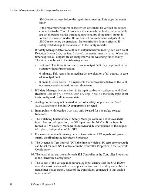
SM Controller reset before the repair timer expires. This stops the repair<br />
timer.<br />
- If the repair timer expires or the switch-off cannot be verified all outputs<br />
connected to the Control Processor that controls the faulty output module<br />
are de-energized via the watchdog functionality. If the faulty output is<br />
located in a non-redundant IO section, all non-redundant outputs of the<br />
SM Controller are de-energized. De-energization is only effected if<br />
safety-related outputs are allocated to the faulty module.<br />
3. If <strong>Safety</strong> <strong>Manager</strong> detects a fault in its output hardware (configured with Fault<br />
Reaction Low or 0mA, see item 2 above), the repair timer is started. When this<br />
timer expires, all outputs are de-energized via the watchdog functionality.<br />
This timer can be set to the following values:<br />
- Not used. The timer is not started so an output fault may be present in the<br />
system without further action.<br />
- 0 minutes. This results in immediate de-energization of all outputs in case<br />
of an output fault.<br />
- 0 hours to 2047 hours. This represents the interval time between the fault<br />
occurrence and automatic system shutdown.<br />
4. If <strong>Safety</strong> <strong>Manager</strong> detects a fault in its input hardware (configured with Fault<br />
Reaction Low, High, Bottom scale, Top scale), the faulty input is set<br />
to its configured Fault Reaction state.<br />
5. Analog outputs may not be used as part of a safety loop when the Test<br />
disabled check box in IO properties is selected.<br />
6. Input points with location COM may only be used for non safety-related<br />
functions.<br />
7. The watchdog functionality of <strong>Safety</strong> <strong>Manager</strong> contains a shutdown (SD)<br />
input. For normal operation, the SD input must be 24 Vdc. If the input is<br />
forced to 0 V, a <strong>Safety</strong> <strong>Manager</strong> shutdown and de-energization of the outputs<br />
take place, independent of the QPP.<br />
8. For more details on IO wiring details, termination of IO signals and power<br />
supply distribution see Hardware Reference.<br />
9. The Diagnostic Test Interval (DTI, the time in which all IO tests are executed)<br />
can be set for each SM Controller in the Controller Properties in the Network<br />
Configurator.<br />
10. The repair timer can be set for each SM Controller in the Controller Properties<br />
in the Hardware Configurator.<br />
11. The values of the voltage monitor analog input channels of the SAI-1620m<br />
modules must be checked in the application to ensure that they are within the<br />
transmitter power supply range of the transmitters connected to that analog<br />
input module.<br />
48 Release 131, Issue 4.2


