

Safety Manager Safety Manual - Tuv-fs.com
Safety Manager Safety Manual - Tuv-fs.com
Safety Manager Safety Manual - Tuv-fs.com

You also want an ePaper? Increase the reach of your titles
YUMPU automatically turns print PDFs into web optimized ePapers that Google loves.
4 – <strong>Safety</strong> <strong>Manager</strong> special functions<br />
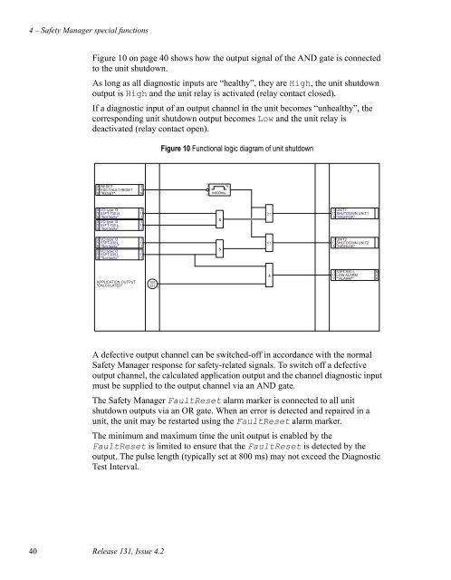
Figure 10 on page 40 shows how the output signal of the AND gate is connected<br />
to the unit shutdown.<br />
As long as all diagnostic inputs are “healthy”, they are High, the unit shutdown<br />
output is High and the unit relay is activated (relay contact closed).<br />
If a diagnostic input of an output channel in the unit be<strong>com</strong>es “unhealthy”, the<br />
corresponding unit shutdown output be<strong>com</strong>es Low and the unit relay is<br />
deactivated (relay contact open).<br />
Figure 10 Functional logic diagram of unit shutdown<br />
A defective output channel can be switched-off in accordance with the normal<br />
<strong>Safety</strong> <strong>Manager</strong> response for safety-related signals. To switch off a defective<br />
output channel, the calculated application output and the channel diagnostic input<br />
must be supplied to the output channel via an AND gate.<br />
The <strong>Safety</strong> <strong>Manager</strong> FaultReset alarm marker is connected to all unit<br />
shutdown outputs via an OR gate. When an error is detected and repaired in a<br />
unit, the unit may be restarted using the FaultReset alarm marker.<br />
The minimum and maximum time the unit output is enabled by the<br />
FaultReset is limited to ensure that the FaultReset is detected by the<br />
output. The pulse length (typically set at 800 ms) may not exceed the Diagnostic<br />
Test Interval.<br />
40 Release 131, Issue 4.2


