Omron A5 Catalogue 2005 1-338 - myAVR
Omron A5 Catalogue 2005 1-338 - myAVR
Omron A5 Catalogue 2005 1-338 - myAVR

Create successful ePaper yourself
Turn your PDF publications into a flip-book with our unique Google optimized e-Paper software.
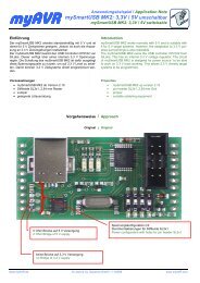
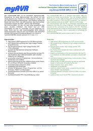
PCB Signal Relay – G5V-1<br />
Ultra-miniature, Highly Sensitive<br />
SPDT Relay for Signal Circuits<br />
■ ROHS compliant.<br />
■ Ultra-miniature at 12.5 x 7.5 x 10 mm<br />
(L x W x H).<br />
■ Wide switching power of 1 mA to 1 A.<br />
■ High sensitivity: 150mW nominal coil power.<br />
■ Fully sealed construction.<br />
■ International 2.54mm terminal pitch.<br />
■ Conforms to FCC Part 68 requirements for<br />
coil to contacts. 4+<br />
Ordering Information<br />
Classification<br />
Contact form Contact type Contact material Structure<br />
SPDT Single crossbar Ag + Au-clad Fully sealed G5V-1<br />
Model<br />
Note: When ordering, add the rated coil voltage to the model number.<br />
Example: G5V-1 12 VDC<br />
Rated coil voltage<br />
Model Number Legend<br />
G5V -<br />
1 2<br />
VDC<br />
1. Contact Form<br />
1: SPDT<br />
2. Rated Coil Voltage<br />
3, 5, 6, 9, 12, 24 VDC<br />
Specifications<br />
■ Coil Ratings<br />
Rated voltage 3 VDC 5 VDC 6 VDC 9 VDC 12 VDC 24 VDC<br />
Rated current 50 mA 30 mA 25 mA 16.7 mA 12.5 mA 6.25 mA<br />
Coil resistance 60 Ω 167 Ω 240 Ω 540 Ω 960 Ω 3,840 Ω<br />
Coil inductance Armature OFF 0.05 0.15 0.20 0.45 0.85 3.48<br />
(H) (ref. value) Armature ON 0.11 0.29 0.41 0.93 1.63 6.61<br />
Must operate voltage<br />
Must release voltage<br />
80% max. of rated voltage<br />
10% min. of rated voltage<br />
Max. voltage 200% of rated voltage at 23°C<br />
Power consumption<br />
Approx. 150 mW<br />
Note: 1. The rated current and coil resistance are measured at a coil temperature of 23°C with a tolerance of ±10%.<br />
2. Operating characteristics are measured at a coil temperature of 23°C.<br />
178
PCB Signal Relay – G5V-1<br />
■ Contact Ratings<br />
Load Resistive load (cosø = 1)<br />
Rated Load<br />
0.5 A at 125 VAC; 1 A at 24 VDC<br />
Contact Material<br />
Ag + Au-clad<br />
Rated Carry Current<br />
2 A<br />
Max. switching voltage 125 VAC, 60 VDC<br />
Max. switching current 1 A<br />
Max. switching power<br />
62.5 VA, 30 W<br />
Failure rate (reference value) 1 mA at 5 VDC<br />
Note: P level: λ 60 = 0.1 x 10 -6 /operation.<br />
Signal Relays<br />
■ Characteristics<br />
Contact resistance<br />
Operate time<br />
Release time<br />
Bounce Time<br />
Max. operating frequency<br />
Insulation resistance<br />
Dielectric strength<br />
100 mΩ max.<br />
5 ms max. (mean value: approx. 2.5 ms)<br />
5 ms max. (mean value: approx. 0.9 ms)<br />
Operate: Approx. 0.2 ms<br />
Release: Approx. 5 ms<br />
Mechanical: 36,000 operations/hr<br />
Electrical: 1,800 operations/hr at rated load<br />
1,000 MΩ min. (at 500 VDC between coil and contacts, at 250 VDC between contacts of same polarity.)<br />
1,000 VAC, 50/60 Hz for 1 min between coil and contacts<br />
400 VAC, 50/60 Hz for 1 min between contacts of same polarity<br />
Impulse withstand voltage 1,500 V (10 x 160 µs) between coil and contacts (conforms to FCC Part 68)<br />
Vibration resistance<br />
Shock resistance Destruction: 1,000 m/s 2<br />
Malfunction: 100 m/s 2<br />
Endurance<br />
Ambient temperature<br />
Destruction: 10 to 55 to 10 Hz, 1.65mm single amplitude (3.3mm double amplitude)<br />
Malfunction: 10 to 55 to 10 Hz, 1.65mm single amplitude (3.3mm double amplitude)<br />
Mechanical: 5,000,000 operations min. (at 18,000 operations/hr)<br />
Electrical: 100,000 operations min. (under rated load, at 1,800 operations/hr)<br />
Operating: -40°C to 70°C (with no icing)<br />
Ambient humidity Operating: 5% to 85%<br />
Weight<br />
Approx. 2 g<br />
■ Approved Standards<br />
UL1950 (File No. E41515)/CSA C22.2 No.0, No.14 (File No. LR31928)<br />
Model Contact form Coil ratings Contact ratings<br />
G5V-1 SPDT 3 to 24 VDC 0.5 A, 125 VAC (general use)<br />
0.3 A, 110 VDC (resistive load)<br />
1 A, 30 VDC (resistive load)<br />
179
PCB Signal Relay – G5V-1<br />
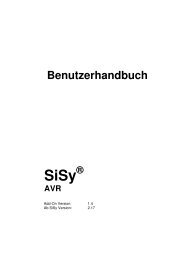
Engineering Data<br />
Switching current (A)<br />
Maximum Switching Power<br />
DC resistive load<br />
AC<br />
resistive<br />
load<br />
Endurance (x10 operations)<br />
3<br />
5,000<br />
3,000<br />
1,000<br />
700<br />
500<br />
300<br />
100<br />
70<br />
50<br />
Endurance<br />
125-VAC<br />
resistive<br />
load<br />
24-VDC resistive load<br />
Maximum coil voltage (%)<br />
Ambient Temperature vs.<br />
Maximum Coil Voltage<br />
Rated coil voltage<br />
Switching voltage (V)<br />
Switching current (A)<br />
Ambient temperature (°C)<br />
Note: The maximum coil voltage refers to the maximum<br />
value in a varying range of operating<br />
power voltage, not a continuous voltage.<br />
Dimensions<br />
Note: 1. All units are in millimeters unless otherwise indicated.<br />
2. Numbers in parentheses are reference values.<br />
3. Tolerance: ±0.1<br />
4. Orientation marks are indicated as follows:<br />
10 max.<br />
(9.9) 0.5<br />
12.5 max.<br />
(12.3)*<br />
7.5 max.<br />
(7.3)*<br />
Terminal Arrangement/<br />
Internal Connections<br />
(Bottom View)<br />
1 2 5<br />
(1.07)<br />
Mounting Holes<br />
(Bottom View)<br />
2.54 7.62<br />
(1.11)<br />
5.08+0.1<br />
3.5<br />
0.5<br />
* Average value<br />
10<br />
9<br />
6<br />
Six, 1-dia. holes<br />
10.16+0.1<br />
(1.11)<br />
(1.07)<br />
180