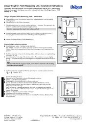
Dräger Polytron 3000 - ancb.it
Dräger Polytron 3000 - ancb.it
Dräger Polytron 3000 - ancb.it

You also want an ePaper? Increase the reach of your titles
YUMPU automatically turns print PDFs into web optimized ePapers that Google loves.
Maintenance<br />
● Sw<strong>it</strong>ch off calibration gas and remove calibration adapter.<br />
● Wa<strong>it</strong> until the measured value drops below the alarm threshold set on the central<br />
un<strong>it</strong>. Otherwise an alarm will be triggered when the maintenance sw<strong>it</strong>ch is returned<br />
to the measuring pos<strong>it</strong>ion immediately after calibration.<br />
1 Set maintenance sw<strong>it</strong>ch to measuring pos<strong>it</strong>ion, left-hand pos<strong>it</strong>ion. The 4 to 20 mA<br />
output changes to measuring mode.<br />
● Ref<strong>it</strong> the front cover of the service port and lock <strong>it</strong> in place by turning clockwise<br />
w<strong>it</strong>h an Allen key (approx. 60 o ).<br />
<strong>Polytron</strong><br />
1<br />
Replacing the sensor<br />
The sensor can be replaced, if necessary, w<strong>it</strong>hout interrupting the power supply in<br />
the explosion-hazard area.<br />
Use only <strong>Dräger</strong>Sensors which are approved for use w<strong>it</strong>h the <strong>Dräger</strong> <strong>Polytron</strong> <strong>3000</strong><br />
transm<strong>it</strong>ter.<br />
Caution:<br />
— When the transm<strong>it</strong>ter is installed in Ex areas zone 22 or Class II, Div. 1 & 2,<br />
Group E, F, G the opening of the housing (inclusive sensor replacement)<br />
must not be done when connected to power (power must be turned off or<br />
the area has to be declassified)! Explosion hazard!<br />
●<br />
Open the front cover of the service port w<strong>it</strong>h an Allen key by turning anticlockwise<br />
(approx. 60 o ). The maintenance sw<strong>it</strong>ch and potentiometers for calibration are now<br />
revealed.<br />
Attention!<br />
Use only a 5 mm Allen key w<strong>it</strong>hout a ball head.<br />
1 Set maintenance sw<strong>it</strong>ch to right-hand pos<strong>it</strong>ion. The 4 to 20 mA output changes to<br />
maintenance mode. In this pos<strong>it</strong>ion, a maintenance signal is relayed to the analogue<br />
output and prevents alarms being triggered.<br />
<strong>Polytron</strong><br />
1<br />
02023758_1.eps<br />
02123758_1.eps<br />
2 Remove bayonet ring from transm<strong>it</strong>ter; pull out old sensor.<br />
3 Remove sensor from packaging. Ensure that the sensor is of the same type as that<br />
specified on the sticker on the measuring un<strong>it</strong>.<br />
● Remove the short-circu<strong>it</strong> strap from the sensor (if <strong>it</strong> is f<strong>it</strong>ted).<br />
● There is a coded connector on the back of the sensor. Place the sensor in the<br />
opening w<strong>it</strong>h the connector at the back and the <strong>Dräger</strong> logo at the front.<br />
Before plugging the connector in the socket, ensure that they are identically coded.<br />
Incorrect connection can damage the sensor!<br />
2 Secure sensor in transm<strong>it</strong>ter w<strong>it</strong>h bayonet ring.<br />
Attention:<br />
For use in Zone 22, tighten the locking screw (2 mm Allen screw) of the<br />
sensor bayonet ring tight enough to ensure that the bayonet ring is<br />
secured against unintended loosening.<br />
2<br />
3<br />
<strong>Polytron</strong><br />
02223758_1.eps<br />
●<br />
Wa<strong>it</strong> until the measured value drops below the alarm threshold set on the central<br />
un<strong>it</strong>. Otherwise an alarm will be triggered when the maintenance sw<strong>it</strong>ch is returned<br />
to the measuring pos<strong>it</strong>ion immediately after the sensor replacement.<br />
17