insights Volume 10 No. 2 - Engineers Notebook - Dresser-Rand
insights Volume 10 No. 2 - Engineers Notebook - Dresser-Rand
insights Volume 10 No. 2 - Engineers Notebook - Dresser-Rand

You also want an ePaper? Increase the reach of your titles
YUMPU automatically turns print PDFs into web optimized ePapers that Google loves.
ENGINEER’S<br />
notebook<br />
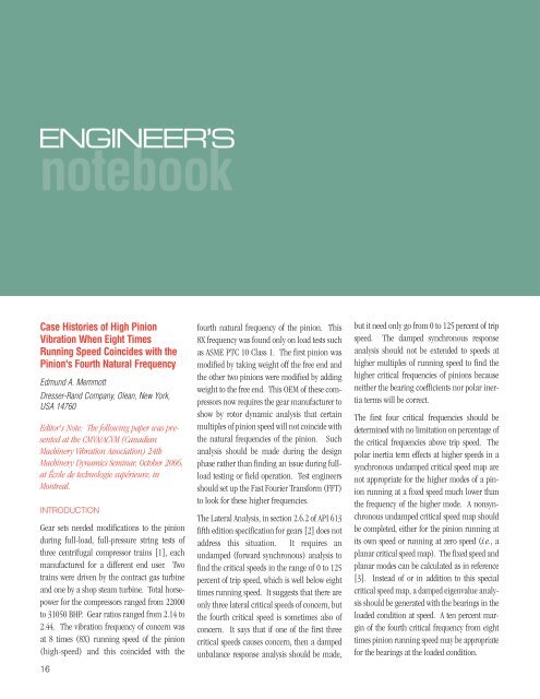
Case Histories of High Pinion<br />
Vibration When Eight Times<br />
Running Speed Coincides with the<br />
Pinion's Fourth Natural Frequency<br />
Edmund A. Memmott<br />
<strong>Dresser</strong>-<strong>Rand</strong> Company, Olean, New York,<br />
USA 14760<br />
Editor's <strong>No</strong>te: The following paper was presented<br />
at the CMVA/ACVM (Canadian<br />
Machinery Vibration Association) 24th<br />
Machinery Dynamics Seminar, October 2006,<br />
at École de technologie supérieure, in<br />
Montreal.<br />
INTRODUCTION<br />
Gear sets needed modifications to the pinion<br />
during full-load, full-pressure string tests of<br />
three centrifugal compressor trains [1], each<br />
manufactured for a different end user. Two<br />
trains were driven by the contract gas turbine<br />
and one by a shop steam turbine. Total horsepower<br />
for the compressors ranged from 22000<br />
to 3<strong>10</strong>50 BHP. Gear ratios ranged from 2.14 to<br />
2.44. The vibration frequency of concern was<br />
at 8 times (8X) running speed of the pinion<br />
(high-speed) and this coincided with the<br />
16<br />
fourth natural frequency of the pinion. This<br />
8X frequency was found only on load tests such<br />
as ASME PTC <strong>10</strong> Class 1. The first pinion was<br />
modified by taking weight off the free end and<br />
the other two pinions were modified by adding<br />
weight to the free end. This OEM of these compressors<br />
now requires the gear manufacturer to<br />
show by rotor dynamic analysis that certain<br />
multiples of pinion speed will not coincide with<br />
the natural frequencies of the pinion. Such<br />
analysis should be made during the design<br />
phase rather than finding an issue during fullload<br />
testing or field operation. Test engineers<br />
should set up the Fast Fourier Transform (FFT)<br />
to look for these higher frequencies.<br />
The Lateral Analysis, in section 2.6.2 of API 613<br />
fifth edition specification for gears [2] does not<br />
address this situation. It requires an<br />
undamped (forward synchronous) analysis to<br />
find the critical speeds in the range of 0 to 125<br />
percent of trip speed, which is well below eight<br />
times running speed. It suggests that there are<br />
only three lateral critical speeds of concern, but<br />
the fourth critical speed is sometimes also of<br />
concern. It says that if one of the first three<br />
critical speeds causes concern, then a damped<br />
unbalance response analysis should be made,<br />
but it need only go from 0 to 125 percent of trip<br />
speed. The damped synchronous response<br />
analysis should not be extended to speeds at<br />
higher multiples of running speed to find the<br />
higher critical frequencies of pinions because<br />
neither the bearing coefficients nor polar inertia<br />
terms will be correct.<br />
The first four critical frequencies should be<br />
determined with no limitation on percentage of<br />
the critical frequencies above trip speed. The<br />
polar inertia term effects at higher speeds in a<br />
synchronous undamped critical speed map are<br />
not appropriate for the higher modes of a pinion<br />
running at a fixed speed much lower than<br />
the frequency of the higher mode. A nonsynchronous<br />
undamped critical speed map should<br />
be completed, either for the pinion running at<br />
its own speed or running at zero speed (i.e., a<br />
planar critical speed map). The fixed speed and<br />
planar modes can be calculated as in reference<br />
[3]. Instead of or in addition to this special<br />
critical speed map, a damped eigenvalue analysis<br />
should be generated with the bearings in the<br />
loaded condition at speed. A ten percent margin<br />
of the fourth critical frequency from eight<br />
times pinion running speed may be appropriate<br />
for the bearings at the loaded condition.
UNDAMPED CRITICAL SPEEDS<br />
The standard forward synchronous critical speed map will be shown to be inaccurate for higher<br />
modes such as the fourth when the fourth is well above the running speed. The planar critical<br />
speed map for the shaft at rest provides sufficiently accurate results for tuning the fourth natural<br />
frequency so that it does not occur at 8 times running speed. This map should be easy to plot and<br />
does not involve the use of bearing properties, bearing programs, or damped eigenvalue programs.<br />
The undamped natural frequency calculation uses a moment equation [3] with the term:<br />
ABSTRACT<br />
Three case studies are described to illustrate pinion vibration during<br />
full-load, full-pressure string tests of centrifugal compressor trains.<br />
The vibration frequency of interest in the studies was eight times the<br />
speed of the pinion, which was near the pinion's fourth lateral natural<br />
frequency. Simple modifications to the pinion lowered the vibration<br />
to appropriate levels. Proper use of the undamped critical<br />
speed map for higher modes well above synchronous speed will be<br />
discussed. Modifications to the dynamics paragraphs of the API 613<br />
Gear Specification will be presented for consideration.<br />
The compressor OEM's original critical speed<br />
program only calculated forward synchronous<br />
frequencies. It was based on an earlier version<br />
of the undamped critical speed program [3].<br />
The compressor OEM modified the original<br />
program to add the capability to calculate frequencies<br />
for backward synchronous, forward<br />
and backward for a fixed shaft speed, and planar<br />
= shaft at rest. The planar option is used<br />
for the modeling of the modal ring test of<br />
rotors. Modifications for the fixed speed option<br />
were verified by comparison with the results<br />
from the Lund stability program [4,5] for the<br />
same model. The program also was verified by<br />
comparing results using the planar option vs.<br />
modal ring test results for an actual rotor.<br />
In the first case study the original and modified<br />
pinion were analyzed for each of the above<br />
models noted above. Forward synchronous,<br />
forward for a fixed speed, planar, backward for<br />
a fixed speed, and backward synchronous<br />
analyses were run to determine which method<br />
possessed the best correlation to the physical<br />
test data. In the second case study, only forward<br />
synchronous, planar, and backward syn-<br />
Continued on page 18<br />
17
ENGINEER’S<br />
notebook<br />
chronous analyses were run for the original<br />
and modified pinion. In the third case study,<br />
only the planar analysis was run for the original<br />
and modified pinion.<br />
FIRST CASE HISTORY<br />
A sketch of the train for the first case history is<br />
shown in Figure 1. This train was string tested<br />
in 2002 at the gas turbine manufacturer's facility<br />
on full-load, full-pressure using hydrocarbon<br />
gas with the contract gas turbine used as<br />
the driver. Three identical trains were shipped<br />
to an offshore platform. The compressors were<br />
designed for natural gas injection at a final discharge<br />
pressure of 45<strong>10</strong> PSIA (311 BAR). The<br />
total BHP is 3<strong>10</strong>40 for the compressors. The<br />
low-speed range is 3840 to 5040 RPM and the<br />
high-speed range is 8214 to <strong>10</strong>780 RPM with a<br />
Figure 3 - Synchronous Forward Critical Speed Map Case History<br />
1 - Original Pinion<br />
18<br />
gear ratio of 2.14. The gear is a double helical<br />
design and the pinion (high-speed) bearings<br />
are of the tilt-pad type.<br />
A vibration frequency issue was found during the<br />
full-load string test and it coincided with 8 times<br />
the running (high) speed. See Figure 2, a waterfall<br />
plot of amplitude from the test. An amplitude<br />
of twenty-seven (27) microns is well over<br />
the 20 percent allowable limit for any discrete,<br />
nonsynchronous vibration in 4.3.2.2.9 of API<br />
613 fifth edition [2]. There also were measurements<br />
of up to <strong>10</strong> G's (acceleration)<br />
at 8X running speed of<br />
the pinion measured on the<br />
gearbox. Ten (<strong>10</strong>) G's is well<br />
above the 4 G's limit for overall<br />
operation as defined in 2.7.1.3<br />
of API 613 fifth edition [2].<br />
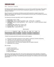
Figure 3 is a calculated forward synchronous<br />
critical speed map for the original pinion,<br />
where … = shaft speed = Ω = whirl frequency<br />
in Formula 1. This map does not indicate a<br />
good match to the test data. By extending the<br />
bearing stiffness lines, the calculated fourth<br />
natural frequency appears to be about 90000<br />
cpm. This is much higher than the 76500 cpm<br />
determined in the full load test. The tilt-pad<br />
bearing coefficients were determined by the<br />
compressor manufacturer by using the tilt-pad<br />
bearing progam as described in [6].<br />
Figure 1 - Train Sketch - Case History 1 Figure 2 - Waterfall Plot - Case History 1 - Original Pinion<br />
Figure 4 - Fixed Speed = <strong>10</strong>780 RPM Forward Critical Speed Map<br />
Case History 1 - Original Pinion
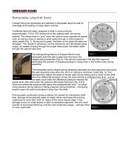
Figure 5 - Original Pinion - Case History 1 - Fourth Undamped<br />
Natural Frequencies<br />
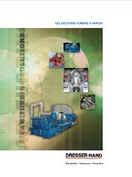
Figure 4 is a calculated forward critical speed<br />
map for a fixed speed of <strong>10</strong>780 RPM, which is<br />
the maximum continuous speed. This is where<br />
ω = shaft speed is fixed at <strong>10</strong>780 RPM and Ω<br />
= whirl frequency is independent of ω in<br />
Formula 1. This map indicates much better<br />
correlation between the tested frequency of<br />
76500 cpm and the calculated fourth frequency<br />
on this map of about 80000 cpm.<br />
Figure 5 pertains to the original pinion and<br />
plots the calculated fourth undamped natural<br />
frequency vs. bearing stiffness for the five different<br />
ways to run the undamped critical speed<br />
program (forward synchronous, forward fixed<br />
speed, planar, backward fixed speed, and backward<br />
synchronous). The fixed speed is the<br />
maximum continuous speed of the pinion. The<br />
curve for the fourth natural frequency is pulled<br />
Figure 7 - Sketch of Modified Pinion - Case History 1<br />
from a critical speed map for each of these conditions<br />
and plotted on one map. Also shown on<br />
Figure 5 are 8 times the minimum governor<br />
speed and 8 times the maximum continuous<br />
speed of the pinion. The best way to correlate<br />
between 8 times = 76500 CPM and the calculated<br />
frequencies is to use forward fixed, planar,<br />
and backward fixed, all of which provide similar<br />
results. The bearing stiffness is approximately<br />
5 to <strong>10</strong> million LB/IN at 3<strong>10</strong>00 HP.<br />
Figure 6 displays the calculated fourth<br />
undamped mode of the original pinion at the<br />
fixed speed of <strong>10</strong>780 RPM (= maximum continuous<br />
speed) at 5 million bearing stiffness.<br />
The frequency is 78<strong>10</strong>6 CPM, which gives a<br />
good match to the tested value of 76500 CPM.<br />
The blind end is on the left side of the plot.<br />
Because the highest amplitude is on the blind<br />
Figure 6 - Original Pinion - Case History 1 - Fourth Forward<br />
Mode = 78<strong>10</strong>6 CPM at Fixed Speed<br />
end, the most effective way to change the location<br />
of the natural frequency is to either add or<br />
remove weight from the blind end.<br />
The pinion was modified to raise the fourth<br />
natural frequency by removing mass from the<br />
blind end of the pinion. Figure 7 is a sketch of<br />
the modified pinion. On a subsequent load test<br />
the modified pinion did not indicate the high<br />
G's acceleration issue nor did it indicate a<br />
vibration frequency issue at eight times running<br />
speed.<br />
Figure 8 pertains to the modified pinion and<br />
displays the calculated fourth undamped natural<br />
frequency vs. bearing stiffness for the five<br />
different ways to run the undamped critical<br />
speed program (as stated above). The fixed<br />
speed is the maximum continuous speed of the<br />
Continued on page 20<br />
Figure 8 - Modified Pinion - Case History 1 - Fourth Undamped<br />
Natural Frequencies<br />
19
ENGINEER’S<br />
notebook<br />
pinion. As the bearing is loaded, the fourth<br />
natural frequency (for forward fixed, planar,<br />
and backward fixed speed = maximum continuous<br />
speed), is raised above 8 times the running<br />
speed range of the pinion.<br />
Figure <strong>10</strong> - Vibration Spectrum - Case History 2 - Original Pinion<br />
Figure 9 - Train Sketch - Case History 2<br />
Figure 11 - Original Pinion - Case History 2 - Fourth Undamped<br />
Natural Frequencies<br />
20<br />
A damped eigenvalue analysis was conducted<br />
by the compressor OEM using the Lund stability<br />
program [4-5] and the tilt-pad bearing program<br />
[6]. For the original pinion, the fourth<br />
damped natural frequency was calculated to be<br />
77,000 CPM with a log dec of 0.7 to 1.0. The<br />
calculated frequency agrees very closely with<br />
the tested value of 76500 CPM. But this calculated<br />
log dec of 0.7 to 1.0 was not high enough<br />
to avoid excitation at 77000 CPM because during<br />
the load test there was substantial horsepower<br />
going through the pinion. One way to<br />
think of this is to view the amplification factor<br />
as approximately Pi/log dec (in the range 4.5<br />
to 3.1); thus the frequency is not critically<br />
damped (amplification factor < 2.5) as per<br />
2.6.1.2 of [2]. For the modified pinion the<br />
fourth damped natural frequency was calculated<br />
to be <strong>10</strong>0,000 to <strong>10</strong>6,000 CPM with a log dec<br />
of 0.4 to 0.6. <strong>No</strong>te that 8xMCOS = 8x<strong>10</strong>780 =<br />
86240 and <strong>10</strong>0000 CPM for the modified pinion<br />
is well above this..<br />
SECOND CASE HISTORY<br />
A sketch of the train for the second case history<br />
is shown in Figure 9. This train was string tested<br />
in 2003 at the compressor manufacturer's<br />
facility at full-load, full-pressure with hydrocarbon<br />
gas with the contract gas turbine as the<br />
driver. Four identical trains were shipped to an<br />
offshore platform. The compressors were<br />
designed for natural gas injection at a final discharge<br />
pressure of 6621 PSIA (457 BAR). The<br />
total BHP is 30427 for the compressors at the<br />
certified condition. The low-speed range is 3360<br />
to 5040 RPM and the high-speed range is 7739<br />
Figure 12 - Modified Pinion - Case History 2 - Fourth Undamped<br />
Natural Frequencies
Figure 13 - Vibration Spectrum - Case History 2 - Modified Pinion<br />
Figure 14 - Train Sketch - Case History 3<br />
to 11608 RPM with a gear ratio of 2.30. The<br />
gear is a double helical design and the pinion<br />
(high-speed) bearings are of the tilt-pad type.<br />
A vibration frequency issue was found during<br />
the full-load, full-pressure string test and it<br />
coincided with 8 times the running (high)<br />
speed. See Figure <strong>10</strong>, a vibration spectrum of<br />
amplitude vs. frequency from the test. The peak<br />
on the right at 1353 hz shows an amplitude of<br />
0.26 mils of 8X frequency. The running speed<br />
of the pinion was 169 hz = <strong>10</strong>148 CPM and<br />
1353 hz/8 = 169 hz. The vibration amplitude<br />
of 0.26 mils is just over the 20 percent allowable<br />
limit for discrete, nonsynchronous vibration in<br />
4.3.2.2.9 of API 613 fifth edition [2].<br />
Figure 11, for the original pinion of Case<br />
History 2, is the same type of plot of the calculated<br />
fourth undamped natural frequency vs.<br />
bearing stiffness as displayed in Figure 5 for<br />
Case History 1, except that it does not show the<br />
calculated frequencies for fixed-speed forward<br />
and fixed-speed backward, as they are very<br />
close to the planar. The test vibration frequency<br />
of 81180 CPM is equal to the calculated<br />
fourth planar frequency at 8 times speed. As<br />
noted above, the test data was derived from a<br />
pinion speed of <strong>10</strong>148 RPM, which is below the<br />
maximum continuous speed of 11608 RPM.<br />
After a weight was added to the free or blind<br />
end of the pinion, the calculated fourth natural<br />
frequency shifted to a frequency below 8<br />
times running speed range. The added weight<br />
is negligible compared to the load that is transmitted<br />
to the pinion bearings from the gear.<br />
Figure 12, for the modified pinion of Case<br />
History 2, plots the calculated fourth<br />
undamped natural frequency vs. bearing stiffness<br />
for forward synchronous, planar, and<br />
backward synchronous. The frequency of concern<br />
is the planar. The calculated fourth frequency<br />
is below the 8X running speed range.<br />
Figure 13 shows a vibration spectrum of amplitude<br />
vs. frequency for a load test of the modified<br />
pinion; in which the vibration frequency<br />
issue at 8X running speed is not indicated.<br />
THIRD CASE HISTORY<br />
A sketch of the train for the third case history is<br />
shown in Figure 14. This train was string tested<br />
in 2005 at the compressor manufacturer's<br />
facility on full-load, full-pressure with hydrocarbon<br />
gas with a shop steam turbine instead<br />
of the gas turbine as the driver. The train was<br />
shipped to an offshore platform. The compressors<br />
were designed for natural gas injection at<br />
a final discharge presssure of 3612 PSIA (249<br />
BAR). The total BHP is 22112 for the compressors<br />
at the certified condition. The low-speed<br />
range is 4080 to 5040 RPM and the high-speed<br />
range is 9960 to 12304 RPM with a gear ratio<br />
of 2.44. The gear is a double helical design<br />
and the pinion (high-speed) bearings are of<br />
the tilt pad type.<br />
A vibration frequency issue was found during<br />
the full- load, full-pressure string test that<br />
coincided with 8 times the running (high)<br />
speed. See Figure 15, a vibration spectrum of<br />
amplitude vs. frequency from the test. The<br />
peak on the right at 1582 hz exceeds 1 mil<br />
amplitude, well over the 20 percent allowable<br />
limit by 4.3.2.2.9 of API 613 fifth edition [2].<br />
Continued on page 22<br />
21
ENGINEER’S<br />
notebook 198 hz and is shown as the peak on the left.<br />
There were up to 4 G's of acceleration at 8<br />
times running speed of the pinion measured<br />
on the gear box. The running speed of the pinion<br />
was 198 hz = 11865 cpm and 1582 hz/8 =<br />
Figure 15 - Vibration Spectrum - Case History 3 - Original Pinion<br />
22<br />
μm Peak-Peak X Vibration<br />
Weight was added to the free or blind end of the<br />
pinion to lower the fourth natural frequency.<br />
Figure 16 shows a similar plot of the calculated<br />
krpm<br />
Figure 16 - Original vs. Modified Pinion - Case History 3 Fourth Undamped Planar Natural<br />
Frequency<br />
fourth natural frequency vs. bearing stiffness as<br />
displayed before, except that it shows only the<br />
calculated planar frequencies and the results for<br />
the original and modified pinion are on the<br />
same plot. The test vibration frequency of 95000<br />
CPM observed with the original pinion is close to<br />
the calculated fourth planar frequency at 8<br />
times running peed for the original pinion. For<br />
the modified pinion with the added weight, the<br />
calculated fourth natural frequency has shifted<br />
below the 8X running speed range.<br />
Figure 17 shows a vibration spectrum of amplitude<br />
vs. frequency for a load test of the modified<br />
pinion, in which the vibration frequency<br />
issue at 8X running speed is not indicated.<br />
MODIFICATIONS TO CONSIDER FOR<br />
API 613 [2]<br />
• An undamped analysis for fixed speed or<br />
planar (0 speed) and at a minimum to <strong>10</strong><br />
times trip speed can be added to Section 2.6.2.1<br />
- Undamped Analysis.<br />
• The number of modes can be changed from<br />
three to four in Section 2.6.2.4 - Modes of<br />
Concern.<br />
• A required separation margin of lateral critical<br />
frequencies from multiples of running<br />
speed, such as eight times running speed, can<br />
be stated in Sections 2.6.2.4.1 or 2.6.2.4.2 -<br />
Separation Margins.<br />
• A new section can be added on Stability<br />
Analysis, including a requirement to provide<br />
the first four modes and their log dec as a function<br />
of load.<br />
• For mechanical tests, as in Section 4.3.2.2.9,<br />
the sweep is at a minimum to four times synchronous<br />
speed of the pinion. For load tests it<br />
should at a minimum be to ten times synchronous<br />
speed.
Figure 17 - Vibration Spectrum - Case History 3 - Modified Pinion<br />
CONCLUSIONS<br />
The case histories above demonstrate that<br />
gearbox pinions can be analyzed and designed<br />
to prevent a vibration issue associated with 8<br />
times pinion speed coinciding with the fourth<br />
natural frequency of the pinion, by simply tuning<br />
the pinion.<br />
Modifications to the dynamics requirements of<br />
the API 613 gear specification [2] may be considered<br />
in order to avoid the vibration issues as<br />
outlined in the case histories.<br />
ACKNOWLEDGEMENTS<br />
The author thanks the management of <strong>Dresser</strong>-<br />
<strong>Rand</strong> Company for its support and permission<br />
to publish this paper. Mark Kuzdzal, Wayne<br />
Andrews, Thomas Soulas, and David Grenell of<br />
D-R edited the text, and Rick Antle of D-R supplied<br />
figures of the test data. Martin Maier, and<br />
Thom Eldridge of D-R also assisted. I would<br />
like to thank Ken Beckman of Lufkin for review<br />
of the earlier presentation on this subject [1].<br />
The information contained in this paper<br />
includes factual data, technical interpretations<br />
and opinions which, while believed to be accurate,<br />
are offered solely for information purposes.<br />
<strong>No</strong> representation, guarantee or warranty,<br />
of any kind, is made concerning such data,<br />
interpretations and opinions including the<br />
accuracy thereof.<br />
REFERENCES<br />
[1] Memmott, E. A., 2005, "Should Pinions of<br />
Gear Sets be Designed to Avoid Critical Speeds at<br />
Eight Times Running Speed?," Case History,<br />
Presented at the Thirty-Fourth Turbomachinery<br />
Symposium, Turbomachinery Laboratory,<br />
Department of Mechanical Engineering, Texas<br />
A&M University, College Station, Texas,<br />
December.<br />
[2] API Standard 613, 5th Edition, 2003,<br />
“Special Purpose Gear Units for Petroleum,<br />
Chemical, and Gas Industry Services,”<br />
February.<br />
[3] Colen, R. B., Gunter, E. J., and Gaston, C.<br />
G., 1982, "Undamped Critical Speed Analysis Of<br />
Rotor Systems - A Manual for use with the<br />
Computer Program CRITSPM," UVA/643078/<br />
MAE81/<strong>10</strong>5R, ROMAC Report <strong>No</strong>. 180, August.<br />
[4] Lund, J. W., 1974, "Stability and Damped<br />
Critical Speeds of a Flexible Rotor in Fluid-<br />
Film Bearings," Trans. ASME, Journal of<br />
Engineering for Industry, pp. 509-517, May.<br />
[5] Smalley, A. J., Almstead, L. G., Lund, J. W.<br />
and Koch, E. S., 1974, "User's Manual - MTI<br />
Cadense Program CAD-25 - Dynamic Stability<br />
of a Flexible Rotor," Mechanical Technology<br />
Inc., February.<br />
[6] Nicholas, J. C., Gunter, E. J., and Allaire, P.<br />
E., 1979, "Stiffness and Damping Coefficients<br />
for the Five-Pad Tilting-Pad Bearing," ASLE<br />
Transactions, Vol. 22, 2, pp. 113-124, April.<br />
BIOGRAPHY<br />
Ed Memmott is a principal rotor dynamics<br />
engineer and has been with <strong>Dresser</strong>-<strong>Rand</strong> since<br />
1973. He has written sixteen other papers on<br />
rotor dynamics, most of them on high-pressure<br />
centrifugal compressors. In October 2005 at<br />
the 23rd Machinery Dynamics Seminar of the<br />
CMVA in Edmonton, he presented a three-hour<br />
short course, “A Review of the Dynamics<br />
Paragraphs of API 617 for Centrifugal<br />
Compressors.” He was on the API subcommittee<br />
that wrote the dynamics paragraphs of the<br />
Seventh Edition of API 617, and on the task<br />
force that wrote the Second Edition of API 684,<br />
“API Standard Paragraphs Rotordynamic<br />
Tutorial.” He belongs to the ASME, the<br />
Vibration Institute, and the MAA. He received<br />
an A.B. from Hamilton College (Phi Beta<br />
Kappa), an A.M. from Brown University, and a<br />
Ph.D. from Syracuse University all in the field<br />
of mathematics. ■<br />
23