
You also want an ePaper? Increase the reach of your titles
YUMPU automatically turns print PDFs into web optimized ePapers that Google loves.
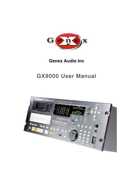
<strong>Genex</strong> Audio Inc<br />
<strong>GX9000</strong> User Manual
Table of Contents<br />
Transport Controls ..................................................................................................................................7<br />
Play......................................................................................................................................................7<br />
Stop .....................................................................................................................................................7<br />
Fast Forward and Fast Reverse..........................................................................................................7<br />
±10 Seconds........................................................................................................................................7<br />
Previous and Next ...............................................................................................................................7<br />
Jog.......................................................................................................................................................8<br />
Shuttle..................................................................................................................................................8<br />
Varispeed ............................................................................................................................................8<br />
Front Panel Displays ...............................................................................................................................9<br />
Timecode Display ................................................................................................................................9<br />
Absolute vs. Relative Timecode in FAT32 Disk Format....................................................................10<br />
Setting the Relative Reference Point ................................................................................................10<br />
Absolute vs. Relative Timecode in <strong>Genex</strong> Disk Format ....................................................................10<br />
Time Remaining / Cue Point Display.................................................................................................11<br />
Menu Operation ....................................................................................................................................12<br />
Displaying and Navigating the Menu.................................................................................................12<br />
Changing Menu Levels......................................................................................................................12<br />
Changing the Value of a Menu Option ..............................................................................................13<br />
Working with Media...............................................................................................................................14<br />
Blanking Plates..................................................................................................................................14<br />
Hard Drives........................................................................................................................................14<br />
Magneto-Optical and DVD Drives .....................................................................................................16<br />
Tape Drives .......................................................................................................................................16<br />
Configuring Storage Devices ................................................................................................................17<br />
Formatting Media...............................................................................................................................21<br />
Projects and File Handling (FAT32 Format Only).................................................................................22<br />
How Do I Create a Project?...............................................................................................................22<br />
How are Project Files Named?..........................................................................................................23<br />
How to Locate Project Files on a Disk Volume .................................................................................23<br />
Navigating Through Folders ..............................................................................................................24<br />
Opening an ADL Project or Audio File ..............................................................................................24<br />
Large File Handling ...........................................................................................................................24<br />
Delete Project ....................................................................................................................................25<br />
Setting the Date and Time.................................................................................................................26<br />
Set the Date.......................................................................................................................................26<br />
Set the Time ......................................................................................................................................26
What Does an ADL Contain? ............................................................................................................26<br />
Audio .....................................................................................................................................................31<br />
Audio Formats ...................................................................................................................................31<br />
Digital Clocks ........................................................................................................................................34<br />
PCM and DSD ...................................................................................................................................34<br />
<strong>Genex</strong> Format....................................................................................................................................35<br />
FAT32................................................................................................................................................35<br />
Sample Rate Conversion...................................................................................................................36<br />
Playback................................................................................................................................................39<br />
Audio Playback..................................................................................................................................39<br />
<strong>Genex</strong> File Format.............................................................................................................................39<br />
AES31 Audio File ..............................................................................................................................39<br />
DSDIFF Audio File.............................................................................................................................39<br />
AES31-DSD Audio File......................................................................................................................39<br />
Loop Playback ...................................................................................................................................40<br />
Locate Operations .............................................................................................................................40<br />
Storing a Timecode in a Locate Memory...........................................................................................41<br />
Using Headphones................................................................................................................................43<br />
Audio Recording....................................................................................................................................45<br />
Making Initial Recordings ..................................................................................................................45<br />
Record Modes ...................................................................................................................................46<br />
Punch In Recording...........................................................................................................................49<br />
Rehearsal ..........................................................................................................................................49<br />
Setting the Pre-Roll and Post-Roll Times..........................................................................................49<br />
Auto Punch ........................................................................................................................................50<br />
Timecode...............................................................................................................................................51<br />
The Take Logging System ....................................................................................................................55<br />
Entering Cue Points...........................................................................................................................56<br />
Presetting Cue Point Counters..........................................................................................................56<br />
Metering and the Display ......................................................................................................................59<br />
System ..................................................................................................................................................61<br />
Upgrading the <strong>GX9000</strong> with New Software ..........................................................................................63<br />
Rear Panel Connections .......................................................................................................................65<br />
RS422 Connector Pinout...................................................................................................................65<br />
I/O Card 25 Way D' Type Pinouts .....................................................................................................66
<strong>GX9000</strong> User Manual Rev 2.1 Transport Controls<br />
Transport Controls<br />
Play<br />
Press the Play button to start forward play at x1 speed. The upper alphanumeric display shows the<br />
current time-code.<br />
Stop<br />
Press the Stop button to cancel the current transport mode.<br />
Fast Forward and Fast Reverse<br />
The operator can use the Fast Forward and Fast Reverse buttons to emulate the locate functions of<br />
a tape deck. Repeated pressing doubles the search speed up to a maximum x32 in either direction.<br />
Fast Forward automatically stops at 24:00:00:00 and Fast Reverse automatically stops at<br />
00:00:00:00. Pressing Play from either Fast Reverse or Fast Forward instantly puts the unit into Play.<br />
Pressing Stop instantly stops the unit. Audio output is muted during Fast Forward and Fast Reverse.<br />
The Fast Forward and Fast Reverse buttons are not disabled when in record; the unit will drop out of<br />
record and start spooling.<br />
±10 Seconds<br />
Press the +10 button to advance the unit 10 seconds in the forward direction. Press the -10 button to<br />
retard the playback position by 10 seconds. If the unit is stopped when either button is pressed the<br />
unit is parked at the new timecode position. If the unit is in play when the buttons are pressed,<br />
playback continues at the new timecode. The +10 and -10 buttons are disabled when in record.<br />
Previous and Next<br />
The Previous button moves the transport to the first cue point prior to the current location. The Next<br />
button selects the next cue point ahead of the current location. If the unit is in Play when either button<br />
is pressed, playback continues from the new location, otherwise the unit is parked at the new location.<br />
The Next and Previous buttons are disabled when in record.<br />
<strong>Genex</strong> Audio Inc Page 7
<strong>GX9000</strong> User Manual Rev 2.1 Transport Controls<br />
Jog<br />
Press the Jog button to put the unit into Jog mode. The Jog LED will light to confirm the mode. In Jog<br />
mode the Rotary Wheel can be used to move audio backwards and forwards in the same way as<br />
moving a piece of tape across a magnetic head. The speed of playback is dependant on the speed of<br />
the Rotary Wheel. To cancel Jog mode press any of the following buttons, Play, Stop, Fast<br />
Forward, Fast Reverse, Jog, Shuttle, Varispeed, or perform a Locate operation. The Jog mode will<br />
not currently operate in DSD mode.<br />
Shuttle<br />
Press the Shuttle button to enable Fast Forward or Fast Reverse in preset increments. The exact<br />
speed is selected using the Rotary Wheel. The following options are available.<br />
0 ±1.0 ±2.0 ±3.0 ±4.0 ±5.0 ±6.0 ±7.0 ±8.0 ±9.0<br />
10.0 ±11.0 ±12.0 ±13.0 ±14.0 ±51.0 ±16.0 ±17.0 ±18.0 ±19.0<br />
20.0 ±25.0 ±30.0 ±35.0 ±40.0 ±45.0 ±50.0<br />
Turn the Rotary Wheel clockwise to select forward motion. Turn the Rotary Wheel counter clockwise<br />
to select reverse motion. Playback automatically stops at 24:00:00:00 in the forward direction and<br />
00:00:00:00 in the reverse direction. To cancel Shuttle mode press the Stop or Shuttle buttons. At<br />
present, no audio is heard during shuttle.<br />
Varispeed<br />
The Varispeed range of the <strong>GX9000</strong> is +/-24%. The rate can be adjusted in increments of 0.06%.<br />
Press the Varispeed button to enable Varispeed mode. The Varispeed LED will light to confirm the<br />
mode. Use the Rotary Wheel to select the desired rate. Pressing Record or pressing the Varispeed<br />
button again will cancel Varispeed mode. Varispeed is currently only available on PCM rates below<br />
50kHz<br />
<strong>Genex</strong> Audio Inc Page 8
<strong>GX9000</strong> User Manual Rev 2.1 Front Panel Displays<br />
Front Panel Displays<br />
The two alphanumeric displays provide information about the configuration of the unit as well as<br />
timecode information relating to the currently selected project and media.<br />
Timecode Display<br />
In basic mode the upper alpha-numeric display shows timecode information. The source and format of<br />
the timecode can be adjusted. Displaying frames is user selectable via the Setup menu. Press the<br />
Timecode button to select the source for the Timecode display. The LED adjacent to the Timecode<br />
button shows the selected Timecode source. The interpretation of ABS, REL and EXT is different<br />
depending on the disk format of the selected volume.<br />
ABS<br />
REL<br />
EXT<br />
<strong>Genex</strong><br />
Time elapsed since<br />
00:00:00:00. The first cluster<br />
of the disk corresponds to<br />
00:00:00:00<br />
Time read from Timecode<br />
track on disk.<br />
Time read from external<br />
Timecode input<br />
Disk Format<br />
FAT32<br />
Time elapsed since midnight<br />
Time elapsed since previously<br />
stored relative origin<br />
Time read from external<br />
Timecode input<br />
Note that, when displaying timecode from an external source, this does not mean that external<br />
timecode will be used as the timecode source for recording. Please see the Timecode section<br />
regarding chasing to external timecode for record and playback.<br />
<strong>Genex</strong> Audio Inc Page 9
<strong>GX9000</strong> User Manual Rev 2.1 Front Panel Displays<br />
Absolute vs. Relative Timecode in FAT32 Disk Format<br />
For a FAT32 formatted volume the absolute (ABS) timecode displayed is the timecode <strong>com</strong>ing into or<br />
being generated by the unit and is relative to midnight on a 24 hour timeline. The user can program a<br />
significant point on the 24 hour timeline as a reference point so that all times are measured from that<br />
reference point. In Relative (REL) mode all times, cue points, locates, etc. are marked relative to the<br />
reference point.<br />
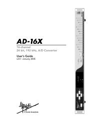
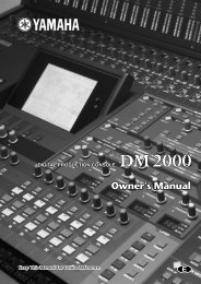
The diagram below illustrates the use of the Relative Reference point for an audio clip starting at<br />
01:00:00:00 on the destination timeline.<br />
Start of Timeline<br />
ABS Zero<br />
Start of Audio Clip at<br />
01:00:00:00<br />
End of Audio Clip<br />
ABS 00:00:00:00 ABS 01:05:00:00 ABS 02:00:00:00<br />
REL --:--:--:-- REL 00:00:00:00<br />
REL origin set to<br />
zero here.<br />
REL 00:55:00:00<br />
ABS and REL Timecode Displays for a FAT32 Disk Format<br />
Setting the Relative Reference Point<br />
Press the Timecode Selector button until the REL LED is lit. Locate to the timecode required to be<br />
the relative origin. Press and hold the -/Clear button while simultaneously pressing the Enter button to<br />
mark the point. The display will now show 00:00:00:00.<br />
Absolute vs. Relative Timecode in <strong>Genex</strong> Disk Format<br />
The <strong>Genex</strong> disk format is a linear format where the current time is directly proportional to the physical<br />
location of the audio on disk, much like a tape machine. Absolute time using this format is analogous<br />
to a tape counter with 00:00:00:00 corresponding to the first cluster on the disk. The ABS timecode is<br />
a measure of how far through the disk you are. The <strong>Genex</strong> format makes a provision for a timecode<br />
track embedded as a sub-code in the recorded audio. The timecode track can be read using the REL<br />
display.<br />
Relative timecode is the timecode read from the timecode track on the disk or generated by the<br />
internal timecode generator. If no timecode is recorded on disk the display reads --:--:--:--.<br />
<strong>Genex</strong> Audio Inc Page 10
<strong>GX9000</strong> User Manual Rev 2.1 Front Panel Displays<br />
Time Remaining / Cue Point Display<br />
In basic mode, the lower alpha-numeric display selectively shows Disk Time Remaining or the current<br />
Cue Point. Press the adjacent Selector button to alternate between the two displays. Disk Time<br />
remaining is displayed in hours, minutes and seconds only; there are no displayed frames. The Time<br />
Remaining display counting down at a similar rate to the timecode display counting up is a useful<br />
verification that data is being recorded to disk properly.<br />
Cue points are records of events that happened during a recording. An event could be music starting,<br />
a wrong note, the start of a new page, a false start, etc. The <strong>GX9000</strong> allows you to log each type of<br />
event as it happens, as a cue point, so that you can quickly and easily find it again. See chapter 12 for<br />
a more detailed description of The Take Logging System.<br />
<strong>Genex</strong> Audio Inc Page 11
<strong>GX9000</strong> User Manual Rev 2.1 Menu Operation<br />
Menu Operation<br />
Many of the features of the <strong>GX9000</strong> are configured using the menu system accessible from the front<br />
panel.<br />
While the menu structure is being accessed the Transport, Chase and Monitoring buttons are<br />
available as normal.<br />
Displaying and Navigating the Menu<br />
Press the Setup button to access the menu. The LED within the Setup button lights up to show that<br />
the menu is being displayed.<br />
Menu headings are shown in the upper alpha numeric display, parameters or values are shown in the<br />
lower display. The menu is three layers deep and the current menu level is indicated by dots in the<br />
upper left hand segment;<br />
one dot indicates one level down<br />
two dots indicates two levels down<br />
The top level of the menu is a selection of functional groups arranged in alphabetic order, no values<br />
are available at this level.<br />
Select a heading/group in the current menu level using the Rotary Wheel.<br />
Changing Menu Levels<br />
To move up and down menu levels use the Parameter Up and Parameter Down buttons. One of the<br />
available submenu headings will now be displayed in the upper alpha numeric display.<br />
To display alternative headings at any menu level, use the Rotary Wheel [].<br />
<strong>Genex</strong> Audio Inc Page 12
<strong>GX9000</strong> User Manual Rev 2.1 Menu Operation<br />
Changing the Value of a Menu Option<br />
To select each of the available values for a chosen menu heading use the Value Up and Value<br />
Down[] buttons.<br />
For some menu headings you can enter values using the numeric keypad.<br />
Press the Enter button to confirm the change. The lower alpha-numeric display will momentarily<br />
indicate 'STORED' if the operation was <strong>com</strong>pleted successfully.<br />
<strong>Genex</strong> Audio Inc Page 13
<strong>GX9000</strong> User Manual Rev 2.1 Working with Media<br />
Working with Media<br />
The <strong>GX9000</strong> has two bays accessible from the front panel and designed to house a variety of SCSI<br />
media devices. Most <strong>com</strong>monly the bays will be fitted with removable Kingston style frames, ready to<br />
receive carriers fitted with Hard Drives or Tape Drives. The bays can also be fitted with MO drives,<br />
recordable DVD drives or any other standard profile SCSI device.<br />
The <strong>GX9000</strong> supports hot-swapping of SCSI devices, you can insert or remove a device at any time<br />
while the unit is powered up. SCSI ID indicators to the right of each drive bay show the SCSI ID of the<br />
device. For the case where a Kingston receiving frame is installed the ID is repeated on the Kingston<br />
frame.<br />
Blanking Plates<br />
The <strong>GX9000</strong> is supplied with one Front Panel blanking plate as standard, fitted to the lower drive bay.<br />
If only external drives are to be used with the <strong>GX9000</strong> a second blanking plate must be fitted to<br />
ensure adequate cooling of the unit. If only one SCSI device is to be fitted, mount the device in the<br />
upper drive bay. When fitting a second device first remove the blanking plate.<br />
Installation and Removal of Front Panel Blanking Plates<br />
No additional information is available at present.<br />
Hard Drives<br />
Installation and Removal of Kingston Receiving Frame<br />
The following picture shows the correct way to connect the internal split SCSI ID cable to two front<br />
panel mounted Kingston Receiving frames so that the rear panel DIP switches correctly control the<br />
ID’s and the correct SCSI ID’s are displayed on the Front Panel.<br />
<strong>Genex</strong> Audio Inc Page 14
<strong>GX9000</strong> User Manual Rev 2.1 Working with Media<br />
These pictures show how to connect the SCSI ID cable supplied with the Kingston caddy to<br />
a Hard Drive so that the SCSI ID information is passed all of the way to the drive.<br />
<strong>Genex</strong> Audio Inc Page 15
<strong>GX9000</strong> User Manual Rev 2.1 Working with Media<br />
Compatible Hard Drives<br />
Most 10k SCSI hard-drives are suitable. We re<strong>com</strong>mend using Seagate Cheatah, Fujitsu MAP, MAS<br />
or MAP drives or IBM Ultrastar drives<br />
Inserting a Drive<br />
Removing a Drive<br />
Magneto-Optical and DVD Drives<br />
Compatible MO Drives<br />
1. Sony SMO-F551/S: 5.2GB MO-drive<br />
2. Sony SMO-F561/S: 9.1GB MO-drive<br />
3. Panasonic DVD-RAM drives<br />
Note that both of these drives require a special “audio” version of firmware loaded. Contact <strong>Genex</strong> for<br />
more details.<br />
Installing a Drive<br />
Inserting a Disk<br />
Removing a Disk<br />
Tape Drives<br />
Compatible Tape Drives<br />
1. Sony AIT-2 and AIT-3 drives are suitable<br />
2. Hewlett Packard LTO drives<br />
Installing a Tape Drive<br />
Inserting a Tape<br />
Removing a Tape<br />
<strong>Genex</strong> Audio Inc Page 16
<strong>GX9000</strong> User Manual Rev 2.1 Working with Media<br />
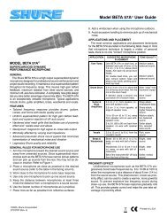
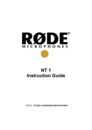
Configuring Storage Devices<br />
Primary Drive<br />
SCSI <br />
<br />
.Primary<br />
- - 2 - - - - I<br />
The <strong>GX9000</strong> is designed to operate with multiple storage devices in a variety<br />
of configurations. Through the SCSI menu you can configure one drive to<br />
mirror another, have two separate drives behave as one larger drive, or use<br />
one drive to insure another. You can also control simple copy or backup<br />
operations from this menu. More <strong>com</strong>plex backup and file handling is<br />
accessible from the GXR Remote Control Software.<br />
The internal SCSI bus of the <strong>GX9000</strong> can be connected to the two front panel<br />
drive bays and is also accessible via a 68 way connector at the rear of the<br />
unit. The bus is terminated at the onboard SCSI controller and should also be<br />
terminated at the last SCSI device on the bus. If no external drive is<br />
connected, the bus should be terminated using the inbuilt active SCSI<br />
terminator. The rear panel DIP switch 9 next to the rear panel SCSI<br />
connector allows the SCSI termination to be switched on and off as shown<br />
below.<br />
On power up the <strong>GX9000</strong> allocates a primary drive for all record and replay<br />
operations. The unit scans the bus for available SCSI ID’s starting at 0 and<br />
continuing through 15, although currently only ID’s in the range 0-6 should be<br />
used for drives. The <strong>GX9000</strong> automatically allocates the first available drive<br />
as the primary drive. This drive can be either of the front panel mounted<br />
drives or any external SCSI storage device.<br />
You can change the selected primary drive via the Setup menu.<br />
• Press the Setup button.<br />
• Use the Rotary Wheel to select the SCSI menu.<br />
• Press the Parameter Down button and use the Rotary Wheel to display<br />
the .Primary menu.<br />
• The display shows all drives connected to the SCSI bus. Each character<br />
position on the lower display represents one possible SCSI ID. ID 0 is the<br />
leftmost character; ID 7 is the rightmost character. If a drive is detected,<br />
its ID will be displayed in the relevant position. The currently active drive<br />
is shown as a flashing character. The initiator ID is represented by the<br />
character ‘I’. Normally the initiator has an ID of 7; in this case the<br />
character ‘I’ will appear in the rightmost character of the lower display.<br />
• Use the Value Up and Value Down buttons to select an alternative SCSI<br />
device. Note that the cursor is shown as a blinking character which can<br />
be confusing as the currently selected drive is also shown as a blinking<br />
character. Occasionally you may have to use the Value buttons to move<br />
the cursor over a dash (unavailable SCSI ID) to determine which ID is the<br />
currently selected Primary Drive.<br />
• Press the Enter button to log the new drive. The messages ‘Logging<br />
Drive’, ‘Reading Disk’ and ‘Drive Logged’ will be<br />
displayed if the drive is selected successfully.<br />
If you see the message ‘Drive In Use’ then the drive is already<br />
allocated as either an Expansion, Insurance or Mirror Drive. You need to<br />
deselect the drive from its current function before selecting it as a Primary<br />
Drive.<br />
<strong>Genex</strong> Audio Inc Page 17
<strong>GX9000</strong> User Manual Rev 2.1 Working with Media<br />
You can verify the model number and software revision of the select primary<br />
drive from the .DrvType sub-menu within the System menu. This can be<br />
useful if there is any confusion about which device is connected to which<br />
SCSI ID.<br />
• Press the Setup button.<br />
• Use the Rotary Wheel to select the System menu.<br />
• Press the Parameter Down button and use the Rotary Wheel to display<br />
the .DrvType menu. The display shows the model number of the drive<br />
as read from the drive during the Inquiry <strong>com</strong>mand.<br />
• Use the Value Up button to display the firmware revision of the Primary<br />
Drive<br />
Increasing Recording Capacity using Expansion Disk Mode<br />
<br />
SCSI <br />
<br />
.Expand<br />
- - 2 - - - - I<br />
Record capacity can be effectively increased by using two drives as if they<br />
were one larger drive. When the <strong>GX9000</strong> fills the Primary Drive recording will<br />
proceed seamlessly onto the Expansion Drive.<br />
If switchover occurs in AES31 or AES31-DSD modes the ADL file will be<br />
written to the Expansion Drive when Stop is pressed. The ADL will contain<br />
links to the files on the Primary Drive and will know where to find them for<br />
playback.<br />
If the <strong>GX9000</strong> is in the Current record mode the original ADL on the Primary<br />
Drive will not be updated. Only the Expansion Drive will contain the full ADL.<br />
The <strong>GX9000</strong> will automatically Stop when the Expansion Drive is full.<br />
• To select an Expansion Drive press the Setup button.<br />
• Use the Rotary Wheel to select the SCSI menu.<br />
• Press the Parameter Down button and use the Rotary Wheel to display<br />
the .Expansion menu heading.<br />
• The display shows all drives connected to the SCSI bus. Each character<br />
position on the lower display represents one possible SCSI ID. ID 0 is the<br />
leftmost character; ID 7 is the rightmost character. If a drive is detected,<br />
its ID will be displayed in the relevant position. The currently active drive<br />
is shown as a flashing character. The initiator ID is represented by the<br />
character ‘I’. Normally the initiator has an ID of 7; in this case the<br />
character ‘I’ will appear in the rightmost character of the lower display.<br />
• Use the Value Up and Value Down buttons to select an alternative SCSI<br />
device. Note that the cursor is shown as a blinking character which can<br />
be confusing as the currently selected drive is also shown as a blinking<br />
character. Occasionally you may have to use the Value buttons to move<br />
the cursor over a dash (unavailable SCSI ID) to determine which ID is the<br />
currently selected Expansion Drive.<br />
• Press the Enter button to log the drive as an Expansion Drive.<br />
• Deselect Expansion mode and free the Drive by pressing Enter again.<br />
<strong>Genex</strong> Audio Inc Page 18
<strong>GX9000</strong> User Manual Rev 2.1 Working with Media<br />
Insurance Disk Mode<br />
<br />
SCSI <br />
<br />
.Insure<br />
- - 2 - - - - I<br />
When recording to devices such as MO (magneto-optical) disks or DVD Ram<br />
the data rate to disk can vary if an area of the disk surface contains a lot of<br />
errors. Sometimes the disk data rate may reduce to a level below that of the<br />
in<strong>com</strong>ing audio. If this situation persists for more than a few seconds the<br />
<strong>GX9000</strong>’s internal data buffers be<strong>com</strong>e dangerously full and a data error can<br />
result (the red LED on the front panel latches on). The <strong>GX9000</strong> has a<br />
technique to insure against this problem called Insurance Drive Mode. A Hard<br />
Drive can be assigned to be an Insurance Drive. The Hard Drive then<br />
receives clusters of data that can’t be written to the MO Disk or DVD Ram<br />
quickly enough. When Stop is pressed after Record the data is automatically<br />
copied back the Primary Drive. The length of time needed for this copy will<br />
depend on the amount of data written to the Insurance Drive. Under normal<br />
circumstances this time would range from 0 to a few seconds. A countdown<br />
will be displayed if data is being copied.<br />
Note that if the data rate of the Primary Drive is sufficient the Insurance Drive<br />
is not used.<br />
• To allocate a drive as an Insurance Drive press the Setup button.<br />
• Use the Rotary Wheel to select the SCSI menu.<br />
• Press the Parameter Down button and use the Rotary Wheel to display<br />
the .Insure menu heading.<br />
• The display shows all drives connected to the SCSI bus. Each character<br />
position on the lower display represents one possible SCSI ID. ID 0 is the<br />
leftmost character; ID 7 is the rightmost character. If a drive is detected,<br />
its ID will be displayed in the relevant position. The currently active drive<br />
is shown as a flashing character. The initiator ID is represented by the<br />
character ‘I’. Normally the initiator has an ID of 7; in this case the<br />
character ‘I’ will appear in the rightmost character of the lower display.<br />
• Use the Value Up and Value Down buttons to select an alternative SCSI<br />
device. Note that the cursor is shown as a blinking character which can<br />
be confusing as the currently selected drive is also shown as a blinking<br />
character. Occasionally you may have to use the Value buttons to move<br />
the cursor over a dash (unavailable SCSI ID) to determine which ID is the<br />
currently selected Insurance Drive.<br />
• Press the Enter button to log the drive as an Insurance Drive.<br />
• Deselect Insurance mode and free the Drive by pressing Enter again.<br />
<strong>Genex</strong> Audio Inc Page 19
<strong>GX9000</strong> User Manual Rev 2.1 Working with Media<br />
Mirror Mode and Drive Backup<br />
<br />
SCSI <br />
<br />
.Mirror<br />
- - 2 - - - - I<br />
The <strong>GX9000</strong> can record to two storage devices simultaneously. This allows<br />
you to make an identical copy of your recording live and can save a great<br />
deal of backup time normally required after a recording.<br />
There is no limit to the number of channels that can be mirrored, for example<br />
you can simultaneously record 48 channels of DSD data to two drives if<br />
required,<br />
Mirror mode also provides a quick technique for copying a Drive to another<br />
Drive or Tape.<br />
• To allocate a drive as a Mirror Drive press the Setup button.<br />
• Use the Rotary Wheel to select the SCSI menu.<br />
• Press the Parameter Down button and use the Rotary Wheel to display<br />
the .Mirror menu heading.<br />
• The display shows all drives connected to the SCSI bus. Each character<br />
position on the lower display represents one possible SCSI ID. ID 0 is the<br />
leftmost character; ID 7 is the rightmost character. If a drive is detected,<br />
its ID will be displayed in the relevant position. The currently active drive<br />
is shown as a flashing character. The initiator ID is represented by the<br />
character ‘I’. Normally the initiator has an ID of 7; in this case the<br />
character ‘I’ will appear in the rightmost character of the lower display.<br />
• Use the Value Up and Value Down buttons to select an alternative SCSI<br />
device. Note that the cursor is shown as a blinking character which can<br />
be confusing as the currently selected drive is also shown as a blinking<br />
character. Occasionally you may have to use the Value buttons to move<br />
the cursor over a dash (unavailable SCSI ID) to determine which ID is the<br />
currently selected Mirror Drive.<br />
• Press the Enter button to log the drive as a Mirror Drive. The <strong>GX9000</strong><br />
first asks if you wish to Sync the Mirror Drive with the Primary Drive. This<br />
means any data currently on the Primary Drive will be copied to the<br />
Mirror Drive. As you can see this provides a simple method of Backing up<br />
Drives from the front panel without the need for the GXR Control<br />
Software.<br />
EITHER<br />
• Press the Value Down button to choose to skip the Sync process.<br />
‘Skip’ will flash. Press the Enter button to log the Mirror Drive and<br />
select Mirror mode.<br />
OR<br />
• Press the Value Up button to select the Sync process. ‘Sync’ will flash.<br />
Press the Enter button to start the copy.<br />
• The following messages will be displayed as the copy progresses.<br />
Note that the Sync process also supports Tape Devices, such as AIT, LTO<br />
and DLT. To make a Backup from Hard Drive to Tape select the Hard Drive<br />
as the Primary Drive and select the Tape Drive as the Mirror Drive. To restore<br />
a previous Tape backup, log the Tape as the Primary Drive and select the<br />
Hard Drive as the Mirror.<br />
• Deselect Insurance mode and free the Drive by pressing Enter again.<br />
<strong>Genex</strong> Audio Inc Page 20
<strong>GX9000</strong> User Manual Rev 2.1 Working with Media<br />
DSP/Initiator SCSI ID<br />
SCSI <br />
<br />
.Host<br />
Formatting Media<br />
This menu displays the SCSI ID of the initiator (the SCSI controller on the<br />
<strong>GX9000</strong> motherboard).<br />
The host ID can be changed to support another SCSI controller which may<br />
also have an ID of 7, being able to access the drives connected to the<br />
<strong>GX9000</strong> SCSI bus.<br />
• Press the Setup button.<br />
• Use the Rotary Wheel to select the SCSI menu.<br />
• Press the Parameter Down button and use the Rotary Wheel to display<br />
the .Host menu heading.<br />
• Use the Value Up and Value Down buttons to select an alternative SCSI<br />
ID.<br />
• Press the Enter button to make the change.<br />
New media connected to the unit generally needs to be formatted before use.<br />
• Press the Setup button.<br />
• Use the Rotary Wheel to select the Format menu.<br />
• Press the Parameter Down button and use the Rotary Wheel to display<br />
the .DiskFmt menu<br />
• Press the Value Left and Right buttons to select a Disk Format. FAT32<br />
and <strong>Genex</strong> are the two choices. Currently it is not possible to write the<br />
<strong>Genex</strong> format although the unit will playback from previously recorded<br />
<strong>Genex</strong> format disks.<br />
• Press the Enter button.<br />
• Press the Enter button again at the ‘Are You Sure?’ prompt.<br />
The formatting process takes just a few seconds. The disk volume is now<br />
ready for use.<br />
Note that it is not necessary to format Tape Devices as they are formatted ‘on<br />
the fly’ during a backup procedure.<br />
<strong>Genex</strong> Audio Inc Page 21
<strong>GX9000</strong> User Manual Rev 2.1 Projects and File Handling<br />
Projects and File Handling (FAT32 Format Only)<br />
The <strong>GX9000</strong> uses the term Project to describe a file that contains information that can be used to<br />
configure the unit and to control playback. Most <strong>com</strong>monly the file will be an AES31 style Audio<br />
Decision List (ADL). These ADL files have the extension .ADL and can reference many other mono<br />
files.<br />
The simplest project file is a mono audio file. The data in the audio file header tells the machine what<br />
sample rate and bit depth to select to correctly playback the file and the file’s timestamp determines at<br />
what time-code the audio will be heard.<br />
By contrast an ADL project file can contain a long list of events, will reference many other audio files,<br />
and will probably reference other meta-data files which hold relevant information. The rest of this<br />
section will refer to ADL Projects<br />
The <strong>GX9000</strong> can generate two type of ADL Project. The standard AES31 ADL Project will be<br />
generated if the unit is dropped into record using the AES31 File Format in PCM mode. A modified<br />
version of the standard ADL Project will be generated when recording in DSD and is selected through<br />
the AES31DSD File Format. The diagrams below illustrate the differences in the ADL formats.<br />
How Do I Create a Project?<br />
You don’t have to. The recorder automatically creates a project for you when you drop into Record<br />
with some tracks in record ready. That’s unless there is already an ADL Project open in which case<br />
the recorder will automatically add information to the open project file every time you go into record. If<br />
you close the project, then the recorder creates a new one the next time you go into record.<br />
If you use the GXR remote control software, it is possible to define a default project name that is used<br />
as the basis for all folder and ADL names. This obviously aids locating projects on disks containing<br />
several.<br />
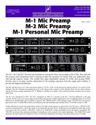
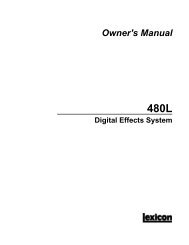
The diagram below illustrates an example file hierarchy with four folders generated from four different<br />
recordings. Note that to generate the new folder the previous *.ADL file must be closed by pressing<br />
the Enter button while the Open menu heading is displayed, or the record mode set to New ADL.<br />
Root<br />
Directory<br />
Gxxx_001<br />
Gxxx_003<br />
Gxxx_004<br />
Gxxx_005<br />
Gxxx_001.ADL<br />
Gxxx_003.ADL<br />
Gxxx_004.ADL<br />
T0100002.DF0<br />
Gxxx_001.CPT<br />
T0100006.WAV<br />
T0100004.WAV<br />
T0100002.DF1<br />
T0100002.DFF<br />
T0200009.WAV<br />
T0200007.WAV<br />
T0100012.DF0<br />
T0200006.DFF<br />
T0300001.WAV<br />
T0300002.WAV<br />
T0100012.DF1<br />
Gxxx_002.ADL<br />
Gxxx_002.CPT<br />
T0100016.DFF<br />
T0200018.DFF<br />
<strong>Genex</strong> Audio Inc Page 22
<strong>GX9000</strong> User Manual Rev 2.1 Projects and File Handling<br />
How are Project Files Named?<br />
Files generated during record are automatically named by the <strong>GX9000</strong>. The naming convention will<br />
depend on the selected file format and is described in the table below;<br />
File Format File Naming Convention Description<br />
DSD IFF Txxccccr.DFF Mono/Multichannel DSD IFF File<br />
Txxccccr.CPT<br />
Cue Point File<br />
AES31-DSD Grrr_ccc.ADL AES31 style ADL with DSD extensions<br />
Txxccccr.DFF<br />
Grrr_ccc.CPT<br />
Mono DSD IFF File<br />
Cue Point File<br />
AES31 Grrr_ccc.ADL AES 31 ADL (Audio Decision List) File<br />
Txxccccr.WAV<br />
Grrr_ccc.CPT<br />
Broadcast Wave File<br />
Cue Point File<br />
Key x Channel identifier<br />
r Random number based on internal timer<br />
c Creation Count (auto increments for each new file/folder)<br />
How to Locate Project Files on a Disk Volume<br />
You can scan through all of the files on a disk volume using the Projects | Open menu. To<br />
speed up the search and to avoid scanning through a large number of files that aren’t relevant,<br />
program the Projects | Filter to display only the file extensions required. For example to<br />
only search for ADL file types,<br />
• Press the Setup button.<br />
• Use the Rotary Wheel to select the Projects menu.<br />
• Press the Parameter Down button and use the Rotary Wheel to display<br />
the .Filter menu<br />
• Press the Value Left and Right buttons to select the file extension<br />
*.ADL. Note that the wildcard entry *.* will display all files within a<br />
folder.<br />
• Press the Enter button.<br />
<strong>Genex</strong> Audio Inc Page 23
<strong>GX9000</strong> User Manual Rev 2.1 Projects and File Handling<br />
Navigating Through Folders<br />
If no ADL Project is open a new folder is created when you drop into Record and the resulting files are<br />
stored in the new folder. If an ADL Project is open the new audio files are added to the open Project<br />
and no new folder is generated. Note new folders are always created off the root directory<br />
• Press the Setup button.<br />
• Use the Rotary Wheel to select the Projects menu.<br />
• Press the Parameter Down button and use the Rotary Wheel to display<br />
the .Open menu.<br />
•<br />
How to Recognize a Folder<br />
The <strong>GX9000</strong> presents the filename and extension as shown below. Folders<br />
can easily be recognized because the three digits to the right of the word<br />
.Open are blank<br />
• Press the Value Up and Value Down buttons to select a folder to open.<br />
The filename of the folder will be shown in the lower display.<br />
• Press the Enter button to open the folder, and display the files within the<br />
folder. The messages Opening Folder will be displayed.<br />
How to Interpret the Contents of a Folder<br />
A folder will contain one or more files whose names can be displayed in the<br />
.Open menu as shown above. You will also see one other entry which is<br />
<strong>com</strong>mon to every folder - . This up-arrow should be selected to step back up<br />
and out of this folder. If the folder is corrupt this arrow may not be visible. In<br />
this case, the drive should be relogged via the SCSI menu which will bring<br />
you back to the root directory.<br />
• Press the Enter button to navigate to the folder above the current folder.<br />
The messages Opening Folder and Folder Opened will be<br />
displayed.<br />
Opening an ADL Project or Audio File<br />
To open an ADL Project or Audio File for playback or for additional recording,<br />
• Press the Setup button.<br />
• Use the Rotary Wheel to select the Projects menu.<br />
• Press the Parameter Down button and use the Rotary Wheel to display<br />
the .Open menu<br />
• Press the Value Left and Value Right buttons to select a file to open.<br />
The extension or file type will be displayed to the right of the word open.<br />
The root of the filename will be shown in the lower display. If the Project<br />
file you’re looking for is in a folder first open the folder as previously<br />
described.<br />
• Press the Enter button. The messages Opening File will be<br />
displayed quickly followed by the message Scanning Files. The<br />
Scanning Files message includes an incrementing File Count<br />
If there are no projects to open, the message No Files or the up-arrow will be shown in the lower<br />
display.<br />
Large File Handling<br />
A high resolution recorder like the <strong>GX9000</strong> can easily generate very large files. This presents a<br />
problem because the largest file size that can be generated on a FAT32 disk is 4GBytes. As an<br />
<strong>Genex</strong> Audio Inc Page 24
<strong>GX9000</strong> User Manual Rev 2.1 Projects and File Handling<br />
example an 8 channel DSD IFF interleaved file will exceed 4GBytes in size after only 25 minutes. The<br />
solution to this problem is different for DSD IFF files and WAV files.<br />
DSD IFF Files<br />
If, during recording, a DSD IFF file exceeds 4GBytes in size a new file is automatically created to<br />
store the extra information. The first file will have the extension DF0 (the 0 tells the <strong>GX9000</strong> to look for<br />
more audio files to append on playback). The new file will have the same root but will be given the<br />
extension DF1. If the 4GB limit is exceeded a second time another file will be created with the same<br />
root but with the extension DF2 and so on. The maximum number of files that can be generated this<br />
way is 10. Files will be given extensions ranging from .DF0 to .DF9. Therefore the maximum record<br />
time for an 8 channel DSD IFF interleaved file is 250 minutes. To playback an extended file you must<br />
open the .DF0 file, as the .DF1 through .DF9 files contain no header information.<br />
WAV Files<br />
If, during recording, a WAV file exceeds 4GBytes in size a new file is automatically created to store<br />
the extra information. The new file is a <strong>com</strong>pletely separate entity with a new random filename and<br />
header and can be opened for playback as a mono WAV file. An entry is made in the ADL file so that<br />
the two files will append on playback.<br />
Delete Project<br />
Rename Project<br />
• Press the Setup button.<br />
• Use the Rotary Wheel to select the Projects menu.<br />
• Press the Parameter Down button and use the Rotary Wheel to display<br />
the .Delete menu<br />
• Press the Value Left and Value Right buttons to select a file to delete.<br />
The root of the filename will be shown in the lower display. You may have<br />
to navigate through folders to find the file.<br />
• Press the Enter button.<br />
• Press the Enter button again at the ‘Are You Sure?’ prompt.<br />
Note If the file is an ADL Project File the unit will delete all files referenced by<br />
the ADL that are in the same folder as the ADL. If the ADL references some<br />
files outside of the current folder or if the files are referenced by another ADL<br />
in the same folder they will not be deleted.<br />
Note You can’t delete a folder unless the folder is empty.<br />
• Press the Setup button.<br />
• Use the Rotary Wheel to select the Projects menu.<br />
• Press the Parameter Down button and use the Rotary Wheel to display<br />
the .Rename menu<br />
• Press the Value Up and Value Down buttons to select a file to rename.<br />
The root of the filename will be shown in the lower display.<br />
• Press the Enter button. One of the characters in the filename will flash.<br />
• Press the Value Left and Value Right buttons to select a character in<br />
the filename to be changed.<br />
• Use the Rotary Wheel to select a new character.<br />
• Repeat the previous two steps as required.<br />
• Press the Enter button to permanently rename the file on disk.<br />
<strong>Genex</strong> Audio Inc Page 25
<strong>GX9000</strong> User Manual Rev 2.1 Projects and File Handling<br />
Setting the Date and Time<br />
The <strong>GX9000</strong> has a real time clock chip which is used to time stamp all<br />
recorded project and audio files. The <strong>GX9000</strong> can also be programmed to<br />
generate Time of Day timecode using the clock. It is therefore important to<br />
set the date and time correctly,<br />
Set the Date<br />
Set the Time<br />
This date is displayed in DD | MM | YY (Day | Month | Year) format. To modify<br />
the date,<br />
• Press the Setup button.<br />
• Use the Rotary Wheel to select the Projects menu.<br />
• Press the Parameter Down button and use the Rotary Wheel to select<br />
the .Date menu.<br />
• Press the Enter button. The colon delimiters will flash to indicate edit<br />
mode, and the fields that are not being edited are blanked out.<br />
• Press the Value Left and Value Right buttons to select a field to be<br />
changed.<br />
• Use the Rotary Wheel to change the field.<br />
• Repeat the previous two steps as required.<br />
• Press the Enter button to set the new date.<br />
This time is displayed in HH:MM:SS (Hours:Minutes:Seconds) format. To<br />
modify the time,<br />
• Press the Setup button.<br />
• Use the Rotary Wheel to select the Projects menu.<br />
• Press the Parameter Down button and use the Rotary Wheel to select<br />
the .Time menu.<br />
• Press the Enter button. The colon delimiters will flash to indicate edit<br />
mode, and the fields that are not being edited are blanked out.<br />
• Press the Value Left and Value Right buttons to select a field to be<br />
changed.<br />
• Use the Rotary Wheel to change the field.<br />
• Repeat the previous two steps as required.<br />
• Press the Enter button to set the new time.<br />
What Does an ADL Contain?<br />
The Project ADL file is a human readable text file that can be opened by any<br />
word processor or text reading application such as Notepad on a PC. The file<br />
can easily be modified by hand to change track routing and slip a track but it<br />
is not re<strong>com</strong>mended. <strong>Genex</strong> provide a simple GUI based editor application<br />
that allow graphical manipulation of the ADL file with edits or changes<br />
immediately sent back to the <strong>GX9000</strong> for review.<br />
The <strong>GX9000</strong> supports two variations of the ADL file. The following example is<br />
a standard AES31 ADL generated in PCM mode for a 48 track 24 / 44.1<br />
recording. The header section contains some general information about the<br />
recording. The middle section lists all of the mono broadcast wave files<br />
generated by the record process, and the end section is a list of events<br />
referencing the audio files. The example ADL shows a 10 minute recording<br />
<strong>Genex</strong> Audio Inc Page 26
<strong>GX9000</strong> User Manual Rev 2.1 Projects and File Handling<br />
<br />
<br />
(ADL_ID)<br />
(ADL_UID)<br />
(VER_ADL_VERSION) 01.01.00.00.03<br />
(VER_CREATOR)<br />
"<strong>Genex</strong> Audio ADL"<br />
(VER_CRTR) 01.01.00.00.03<br />
<br />
<br />
(PROJ_TITLE)<br />
(PROJ_NOTES)<br />
as can be seen from the last two time columns which represent the<br />
Destination In and Destination Out points on the 24 hour timeline.<br />
"_"<br />
1099-12-06T04:33:58-08:00<br />
(PROJ_CREATE_DATE)<br />
(PROJ_ORIGINATOR)<br />
(PROJ_CLIENT_DATA) "----------"<br />
<br />
<br />
(SYS_SRC_OFFSET) 00|00|00|00|0000<br />
(SYS_BIT_DEPTH) 0032<br />
(SYS_AUD_CODEC) "BWF"<br />
(SYS_XFADE_LEN) 00|00|00|00|0352<br />
(SYS_GAIN) 0100.0<br />
<br />
<br />
(SEQ_TITLE)<br />
"UNTITLED SEQUENCE"<br />
(SEQ_DESCRIPT) "_"<br />
(SEQ_SAMPLE_RATE) S44100<br />
(SEQ_FRAME_RATE) 30<br />
(SEQ_ADL_LEVEL) 1<br />
(SEQ_CLEAN)<br />
FALSE<br />
(SEQ_SORT) 0<br />
(SEQ_MULTICHAN) FALSE<br />
(SEQ_DEST_START) 00|00|00|00|0000<br />
<br />
<br />
(Index) 0001 (F) "URL:file://localhost/Disk Dri/T070087A.WAV" _ _ _ _ N<br />
(Index) 0002 (F) "URL:file://localhost/Disk Dri/T1880980.WAV" _ _ _ _ N<br />
(Index) 0003 (F) "URL:file://localhost/Disk Dri/T2990007.WAV" _ _ _ _ N<br />
(Index) 0004 (F) "URL:file://localhost/Disk Dri/T344060E.WAV" _ _ _ _ N<br />
(Index) 0005 (F) "URL:file://localhost/Disk Dri/T4990758.WAV" _ _ _ _ N<br />
(Index) 0006 (F) "URL:file://localhost/Disk Dri/T584097B.WAV" _ _ _ _ N<br />
(Index) 0007 (F) "URL:file://localhost/Disk Dri/T699223E.WAV" _ _ _ _ N<br />
(Index) 0008 (F) "URL:file://localhost/Disk Dri/T799227B.WAV" _ _ _ _ N<br />
(Index) 0009 (F) "URL:file://localhost/Disk Dri/T8740797.WAV" _ _ _ _ N<br />
(Index) 0010 (F) "URL:file://localhost/Disk Dri/T9011353.WAV" _ _ _ _ N<br />
(Index) 0011 (F) "URL:file://localhost/Disk Dri/TA99015A.WAV" _ _ _ _ N<br />
(Index) 0012 (F) "URL:file://localhost/Disk Dri/TB76204F.WAV" _ _ _ _ N<br />
(Index) 0013 (F) "URL:file://localhost/Disk Dri/TC99066C.WAV" _ _ _ _ N<br />
(Index) 0014 (F) "URL:file://localhost/Disk Dri/TD311657.WAV" _ _ _ _ N<br />
(Index) 0015 (F) "URL:file://localhost/Disk Dri/TE68026E.WAV" _ _ _ _ N<br />
(Index) 0016 (F) "URL:file://localhost/Disk Dri/TF99100A.WAV" _ _ _ _ N<br />
(Index) 0017 (F) "URL:file://localhost/Disk Dri/T037054F.WAV" _ _ _ _ N<br />
(Index) 0018 (F) "URL:file://localhost/Disk Dri/T199034D.WAV" _ _ _ _ N<br />
(Index) 0019 (F) "URL:file://localhost/Disk Dri/T299233B.WAV" _ _ _ _ N<br />
(Index) 0020 (F) "URL:file://localhost/Disk Dri/T3900990.WAV" _ _ _ _ N<br />
(Index) 0021 (F) "URL:file://localhost/Disk Dri/T4751625.WAV" _ _ _ _ N<br />
(Index) 0022 (F) "URL:file://localhost/Disk Dri/T599141C.WAV" _ _ _ _ N<br />
(Index) 0023 (F) "URL:file://localhost/Disk Dri/T6720817.WAV" _ _ _ _ N<br />
(Index) 0024 (F) "URL:file://localhost/Disk Dri/T7750831.WAV" _ _ _ _ N<br />
(Index) 0025 (F) "URL:file://localhost/Disk Dri/T8940486.WAV" _ _ _ _ N<br />
(Index) 0026 (F) "URL:file://localhost/Disk Dri/T999044D.WAV" _ _ _ _ N<br />
(Index) 0027 (F) "URL:file://localhost/Disk Dri/TA990610.WAV" _ _ _ _ N<br />
(Index) 0028 (F) "URL:file://localhost/Disk Dri/TB711636.WAV" _ _ _ _ N<br />
(Index) 0029 (F) "URL:file://localhost/Disk Dri/TC68107D.WAV" _ _ _ _ N<br />
(Index) 0030 (F) "URL:file://localhost/Disk Dri/TD992214.WAV" _ _ _ _ N<br />
(Index) 0031 (F) "URL:file://localhost/Disk Dri/TE200836.WAV" _ _ _ _ N<br />
(Index) 0032 (F) "URL:file://localhost/Disk Dri/TF95026B.WAV" _ _ _ _ N<br />
(Index) 0033 (F) "URL:file://localhost/Disk Dri/T0501242.WAV" _ _ _ _ N<br />
(Index) 0034 (F) "URL:file://localhost/Disk Dri/T190239B.WAV" _ _ _ _ N<br />
(Index) 0035 (F) "URL:file://localhost/Disk Dri/T2721933.WAV" _ _ _ _ N<br />
(Index) 0036 (F) "URL:file://localhost/Disk Dri/T3772246.WAV" _ _ _ _ N<br />
(Index) 0037 (F) "URL:file://localhost/Disk Dri/T4992476.WAV" _ _ _ _ N<br />
(Index) 0038 (F) "URL:file://localhost/Disk Dri/T560196F.WAV" _ _ _ _ N<br />
(Index) 0039 (F) "URL:file://localhost/Disk Dri/T6441455.WAV" _ _ _ _ N<br />
(Index) 0040 (F) "URL:file://localhost/Disk Dri/T799232D.WAV" _ _ _ _ N<br />
(Index) 0041 (F) "URL:file://localhost/Disk Dri/T8781875.WAV" _ _ _ _ N<br />
(Index) 0042 (F) "URL:file://localhost/Disk Dri/T9992467.WAV" _ _ _ _ N<br />
(Index) 0043 (F) "URL:file://localhost/Disk Dri/TA340023.WAV" _ _ _ _ N<br />
(Index) 0044 (F) "URL:file://localhost/Disk Dri/TB721792.WAV" _ _ _ _ N<br />
<strong>Genex</strong> Audio Inc Page 27
<strong>GX9000</strong> User Manual Rev 2.1 Projects and File Handling<br />
(Index) 0045 (F) "URL:file://localhost/Disk Dri/TC990049.WAV" _ _ _ _ N<br />
(Index) 0046 (F) "URL:file://localhost/Disk Dri/TD92171C.WAV" _ _ _ _ N<br />
(Index) 0047 (F) "URL:file://localhost/Disk Dri/TE81028D.WAV" _ _ _ _ N<br />
(Index) 0048 (F) "URL:file://localhost/Disk Dri/TF281782.WAV" _ _ _ _ N<br />
<br />
<br />
(Entry) 0001 (Cut) I 0001 01 01 00|00|00|00|0000 00|00|00|00|0387 00|00|10|13|0033 _<br />
(Entry) 0002 (Cut) I 0002 02 02 00|00|00|00|0000 00|00|00|00|0387 00|00|10|13|0033 _<br />
(Entry) 0003 (Cut) I 0003 03 03 00|00|00|00|0000 00|00|00|00|0387 00|00|10|13|0033 _<br />
(Entry) 0004 (Cut) I 0004 04 04 00|00|00|00|0000 00|00|00|00|0387 00|00|10|13|0033 _<br />
(Entry) 0005 (Cut) I 0005 05 05 00|00|00|00|0000 00|00|00|00|0387 00|00|10|13|0033 _<br />
(Entry) 0006 (Cut) I 0006 06 06 00|00|00|00|0000 00|00|00|00|0387 00|00|10|13|0033 _<br />
(Entry) 0007 (Cut) I 0007 07 07 00|00|00|00|0000 00|00|00|00|0387 00|00|10|13|0033 _<br />
(Entry) 0008 (Cut) I 0008 08 08 00|00|00|00|0000 00|00|00|00|0387 00|00|10|13|0033 _<br />
(Entry) 0009 (Cut) I 0009 09 09 00|00|00|00|0000 00|00|00|00|0387 00|00|10|13|0033 _<br />
(Entry) 0010 (Cut) I 0010 10 10 00|00|00|00|0000 00|00|00|00|0387 00|00|10|13|0033 _<br />
(Entry) 0011 (Cut) I 0011 11 11 00|00|00|00|0000 00|00|00|00|0387 00|00|10|13|0033 _<br />
(Entry) 0012 (Cut) I 0012 12 12 00|00|00|00|0000 00|00|00|00|0387 00|00|10|13|0033 _<br />
(Entry) 0013 (Cut) I 0013 13 13 00|00|00|00|0000 00|00|00|00|0387 00|00|10|13|0033 _<br />
(Entry) 0014 (Cut) I 0014 14 14 00|00|00|00|0000 00|00|00|00|0387 00|00|10|13|0033 _<br />
(Entry) 0015 (Cut) I 0015 15 15 00|00|00|00|0000 00|00|00|00|0387 00|00|10|13|0033 _<br />
(Entry) 0016 (Cut) I 0016 16 16 00|00|00|00|0000 00|00|00|00|0387 00|00|10|13|0033 _<br />
(Entry) 0017 (Cut) I 0017 17 17 00|00|00|00|0000 00|00|00|00|0387 00|00|10|13|0033 _<br />
(Entry) 0018 (Cut) I 0018 18 18 00|00|00|00|0000 00|00|00|00|0387 00|00|10|13|0033 _<br />
(Entry) 0019 (Cut) I 0019 19 19 00|00|00|00|0000 00|00|00|00|0387 00|00|10|13|0033 _<br />
(Entry) 0020 (Cut) I 0020 20 20 00|00|00|00|0000 00|00|00|00|0387 00|00|10|13|0033 _<br />
(Entry) 0021 (Cut) I 0021 21 21 00|00|00|00|0000 00|00|00|00|0387 00|00|10|13|0033 _<br />
(Entry) 0022 (Cut) I 0022 22 22 00|00|00|00|0000 00|00|00|00|0387 00|00|10|13|0033 _<br />
(Entry) 0023 (Cut) I 0023 23 23 00|00|00|00|0000 00|00|00|00|0387 00|00|10|13|0033 _<br />
(Entry) 0024 (Cut) I 0024 24 24 00|00|00|00|0000 00|00|00|00|0387 00|00|10|13|0033 _<br />
(Entry) 0025 (Cut) I 0025 25 25 00|00|00|00|0000 00|00|00|00|0387 00|00|10|13|0033 _<br />
(Entry) 0026 (Cut) I 0026 26 26 00|00|00|00|0000 00|00|00|00|0387 00|00|10|13|0033 _<br />
(Entry) 0027 (Cut) I 0027 27 27 00|00|00|00|0000 00|00|00|00|0387 00|00|10|13|0033 _<br />
(Entry) 0028 (Cut) I 0028 28 28 00|00|00|00|0000 00|00|00|00|0387 00|00|10|13|0033 _<br />
(Entry) 0029 (Cut) I 0029 29 29 00|00|00|00|0000 00|00|00|00|0387 00|00|10|13|0033 _<br />
(Entry) 0030 (Cut) I 0030 30 30 00|00|00|00|0000 00|00|00|00|0387 00|00|10|13|0033 _<br />
(Entry) 0031 (Cut) I 0031 31 31 00|00|00|00|0000 00|00|00|00|0387 00|00|10|13|0033 _<br />
(Entry) 0032 (Cut) I 0032 32 32 00|00|00|00|0000 00|00|00|00|0387 00|00|10|13|0033 _<br />
(Entry) 0033 (Cut) I 0033 33 33 00|00|00|00|0000 00|00|00|00|0387 00|00|10|13|0033 _<br />
(Entry) 0034 (Cut) I 0034 34 34 00|00|00|00|0000 00|00|00|00|0387 00|00|10|13|0033 _<br />
(Entry) 0035 (Cut) I 0035 35 35 00|00|00|00|0000 00|00|00|00|0387 00|00|10|13|0033 _<br />
(Entry) 0036 (Cut) I 0036 36 36 00|00|00|00|0000 00|00|00|00|0387 00|00|10|13|0033 _<br />
(Entry) 0037 (Cut) I 0037 37 37 00|00|00|00|0000 00|00|00|00|0387 00|00|10|13|0033 _<br />
(Entry) 0038 (Cut) I 0038 38 38 00|00|00|00|0000 00|00|00|00|0387 00|00|10|13|0033 _<br />
(Entry) 0039 (Cut) I 0039 39 39 00|00|00|00|0000 00|00|00|00|0387 00|00|10|13|0033 _<br />
(Entry) 0040 (Cut) I 0040 40 40 00|00|00|00|0000 00|00|00|00|0387 00|00|10|13|0033 _<br />
(Entry) 0041 (Cut) I 0041 41 41 00|00|00|00|0000 00|00|00|00|0387 00|00|10|13|0033 _<br />
(Entry) 0042 (Cut) I 0042 42 42 00|00|00|00|0000 00|00|00|00|0387 00|00|10|13|0033 _<br />
(Entry) 0043 (Cut) I 0043 43 43 00|00|00|00|0000 00|00|00|00|0387 00|00|10|13|0033 _<br />
(Entry) 0044 (Cut) I 0044 44 44 00|00|00|00|0000 00|00|00|00|0387 00|00|10|13|0033 _<br />
(Entry) 0045 (Cut) I 0045 45 45 00|00|00|00|0000 00|00|00|00|0387 00|00|10|13|0033 _<br />
(Entry) 0046 (Cut) I 0046 46 46 00|00|00|00|0000 00|00|00|00|0387 00|00|10|13|0033 _<br />
(Entry) 0047 (Cut) I 0047 47 47 00|00|00|00|0000 00|00|00|00|0387 00|00|10|13|0033 _<br />
(Entry) 0048 (Cut) I 0048 48 48 00|00|00|00|0000 00|00|00|00|0387 00|00|10|13|0033 _<br />
<br />
<br />
<br />
<strong>Genex</strong> Audio Inc Page 28
<strong>GX9000</strong> User Manual Rev 2.1 Projects and File Handling<br />
The following example is for an AES31DSD ADL. It shows a 30 channel DSD recording. There are<br />
only a couple of subtle differences to the AES31 style ADL. The Codec now lists DFF files instead of<br />
BWF files, and the sample rate is shown as 117600 which is the number of 24 bit chunks per channel<br />
per second in DSD mode.<br />
<br />
<br />
(ADL_ID)<br />
(ADL_UID)<br />
(VER_ADL_VERSION) 01.01.00.00.03<br />
(VER_CREATOR)<br />
"<strong>Genex</strong> Audio ADL"<br />
(VER_CRTR) 01.01.00.00.03<br />
<br />
<br />
(PROJ_TITLE)<br />
(PROJ_NOTES)<br />
"_"<br />
1099-11-29T21:23:04-08:00<br />
(PROJ_CREATE_DATE)<br />
(PROJ_ORIGINATOR)<br />
(PROJ_CLIENT_DATA) "----------"<br />
<br />
<br />
(SYS_SRC_OFFSET) 00|00|00|00|0000<br />
(SYS_BIT_DEPTH) 0024<br />
(SYS_AUD_CODEC) "DFF"<br />
(SYS_XFADE_LEN) 00|00|00|00|0384<br />
(SYS_GAIN) 0100.0<br />
<br />
<br />
(SEQ_TITLE)<br />
"UNTITLED SEQUENCE"<br />
(SEQ_DESCRIPT) "_"<br />
(SEQ_SAMPLE_RATE) S117600<br />
(SEQ_FRAME_RATE) 30<br />
(SEQ_ADL_LEVEL) 1<br />
(SEQ_CLEAN)<br />
FALSE<br />
(SEQ_SORT) 0<br />
(SEQ_MULTICHAN) FALSE<br />
(SEQ_DEST_START) 00|00|00|00|0000<br />
<br />
<br />
(Index) 0001 (F) "URL:file://localhost/Disk Dri/T066245B.DFF" _ _ _ _ N<br />
(Index) 0002 (F) "URL:file://localhost/Disk Dri/T171061D.DFF" _ _ _ _ N<br />
(Index) 0003 (F) "URL:file://localhost/Disk Dri/T267209A.DFF" _ _ _ _ N<br />
(Index) 0004 (F) "URL:file://localhost/Disk Dri/T399114E.DFF" _ _ _ _ N<br />
(Index) 0005 (F) "URL:file://localhost/Disk Dri/T440103D.DFF" _ _ _ _ N<br />
(Index) 0006 (F) "URL:file://localhost/Disk Dri/T5990171.DFF" _ _ _ _ N<br />
(Index) 0007 (F) "URL:file://localhost/Disk Dri/T6501839.DFF" _ _ _ _ N<br />
(Index) 0008 (F) "URL:file://localhost/Disk Dri/T7921184.DFF" _ _ _ _ N<br />
(Index) 0009 (F) "URL:file://localhost/Disk Dri/T830127F.DFF" _ _ _ _ N<br />
(Index) 0010 (F) "URL:file://localhost/Disk Dri/T924005E.DFF" _ _ _ _ N<br />
(Index) 0011 (F) "URL:file://localhost/Disk Dri/TA991858.DFF" _ _ _ _ N<br />
(Index) 0012 (F) "URL:file://localhost/Disk Dri/TB59133C.DFF" _ _ _ _ N<br />
(Index) 0013 (F) "URL:file://localhost/Disk Dri/TC31005B.DFF" _ _ _ _ N<br />
(Index) 0014 (F) "URL:file://localhost/Disk Dri/TD990130.DFF" _ _ _ _ N<br />
(Index) 0015 (F) "URL:file://localhost/Disk Dri/TE990262.DFF" _ _ _ _ N<br />
(Index) 0016 (F) "URL:file://localhost/Disk Dri/TF990982.DFF" _ _ _ _ N<br />
(Index) 0017 (F) "URL:file://localhost/Disk Dri/T0991195.DFF" _ _ _ _ N<br />
(Index) 0018 (F) "URL:file://localhost/Disk Dri/T1361358.DFF" _ _ _ _ N<br />
(Index) 0019 (F) "URL:file://localhost/Disk Dri/T2641961.DFF" _ _ _ _ N<br />
(Index) 0020 (F) "URL:file://localhost/Disk Dri/T3342295.DFF" _ _ _ _ N<br />
(Index) 0021 (F) "URL:file://localhost/Disk Dri/T4992481.DFF" _ _ _ _ N<br />
(Index) 0022 (F) "URL:file://localhost/Disk Dri/T5151256.DFF" _ _ _ _ N<br />
(Index) 0023 (F) "URL:file://localhost/Disk Dri/T613026A.DFF" _ _ _ _ N<br />
(Index) 0024 (F) "URL:file://localhost/Disk Dri/T761143A.DFF" _ _ _ _ N<br />
(Index) 0025 (F) "URL:file://localhost/Disk Dri/T8912547.DFF" _ _ _ _ N<br />
(Index) 0026 (F) "URL:file://localhost/Disk Dri/T9890803.DFF" _ _ _ _ N<br />
(Index) 0027 (F) "URL:file://localhost/Disk Dri/TA561058.DFF" _ _ _ _ N<br />
(Index) 0028 (F) "URL:file://localhost/Disk Dri/TB93010A.DFF" _ _ _ _ N<br />
(Index) 0029 (F) "URL:file://localhost/Disk Dri/TC99246B.DFF" _ _ _ _ N<br />
(Index) 0030 (F) "URL:file://localhost/Disk Dri/TD991235.DFF" _ _ _ _ N<br />
<br />
<br />
(Entry) 0001 (Cut) I 0001 01 01 00|00|00|00|0000 00|00|00|00|0387 01|21|06|16|0955 _<br />
(Entry) 0002 (Cut) I 0002 02 02 00|00|00|00|0000 00|00|00|00|0387 01|21|06|16|0955 _<br />
(Entry) 0003 (Cut) I 0003 03 03 00|00|00|00|0000 00|00|00|00|0387 01|21|06|16|0955 _<br />
(Entry) 0004 (Cut) I 0004 04 04 00|00|00|00|0000 00|00|00|00|0387 01|21|06|16|0955 _<br />
(Entry) 0005 (Cut) I 0005 05 05 00|00|00|00|0000 00|00|00|00|0387 01|21|06|16|0955 _<br />
(Entry) 0006 (Cut) I 0006 06 06 00|00|00|00|0000 00|00|00|00|0387 01|21|06|16|0955 _<br />
(Entry) 0007 (Cut) I 0007 07 07 00|00|00|00|0000 00|00|00|00|0387 01|21|06|16|0955 _<br />
<strong>Genex</strong> Audio Inc Page 29
<strong>GX9000</strong> User Manual Rev 2.1 Projects and File Handling<br />
(Entry) 0008 (Cut) I 0008 08 08 00|00|00|00|0000 00|00|00|00|0387 01|21|06|16|0955 _<br />
(Entry) 0009 (Cut) I 0009 09 09 00|00|00|00|0000 00|00|00|00|0387 01|21|06|17|1292 _<br />
(Entry) 0010 (Cut) I 0010 10 10 00|00|00|00|0000 00|00|00|00|0387 01|21|06|17|1292 _<br />
(Entry) 0011 (Cut) I 0011 11 11 00|00|00|00|0000 00|00|00|00|0387 01|21|06|17|1292 _<br />
(Entry) 0012 (Cut) I 0012 12 12 00|00|00|00|0000 00|00|00|00|0387 01|21|06|17|1292 _<br />
(Entry) 0013 (Cut) I 0013 13 13 00|00|00|00|0000 00|00|00|00|0387 01|21|06|17|1292 _<br />
(Entry) 0014 (Cut) I 0014 14 14 00|00|00|00|0000 00|00|00|00|0387 01|21|06|17|1292 _<br />
(Entry) 0015 (Cut) I 0015 15 15 00|00|00|00|0000 00|00|00|00|0387 01|21|06|17|1292 _<br />
(Entry) 0016 (Cut) I 0016 16 16 00|00|00|00|0000 00|00|00|00|0387 01|21|06|17|1292 _<br />
(Entry) 0017 (Cut) I 0017 17 17 00|00|00|00|0000 00|00|00|00|0387 01|21|06|17|1292 _<br />
(Entry) 0018 (Cut) I 0018 18 18 00|00|00|00|0000 00|00|00|00|0387 01|21|06|17|1292 _<br />
(Entry) 0019 (Cut) I 0019 19 19 00|00|00|00|0000 00|00|00|00|0387 01|21|06|17|1292 _<br />
(Entry) 0020 (Cut) I 0020 20 20 00|00|00|00|0000 00|00|00|00|0387 01|21|06|17|1292 _<br />
(Entry) 0021 (Cut) I 0021 21 21 00|00|00|00|0000 00|00|00|00|0387 01|21|06|17|1292 _<br />
(Entry) 0022 (Cut) I 0022 22 22 00|00|00|00|0000 00|00|00|00|0387 01|21|06|17|1292 _<br />
(Entry) 0023 (Cut) I 0023 23 23 00|00|00|00|0000 00|00|00|00|0387 01|21|06|17|1292 _<br />
(Entry) 0024 (Cut) I 0024 24 24 00|00|00|00|0000 00|00|00|00|0387 01|21|06|17|1292 _<br />
(Entry) 0025 (Cut) I 0025 25 25 00|00|00|00|0000 00|00|00|00|0387 01|21|06|17|1292 _<br />
(Entry) 0026 (Cut) I 0026 26 26 00|00|00|00|0000 00|00|00|00|0387 01|21|06|17|1292 _<br />
(Entry) 0027 (Cut) I 0027 27 27 00|00|00|00|0000 00|00|00|00|0387 01|21|06|17|1292 _<br />
(Entry) 0028 (Cut) I 0028 28 28 00|00|00|00|0000 00|00|00|00|0387 01|21|06|17|1292 _<br />
(Entry) 0029 (Cut) I 0029 29 29 00|00|00|00|0000 00|00|00|00|0387 01|21|06|17|1292 _<br />
(Entry) 0030 (Cut) I 0030 30 30 00|00|00|00|0000 00|00|00|00|0387 01|21|06|17|1292 _<br />
<br />
<br />
_<br />
<strong>Genex</strong> Audio Inc Page 30
<strong>GX9000</strong> User Manual Rev 2.1 Audio<br />
Audio<br />
Audio Formats<br />
This section describes how to select the audio input source and audio format.<br />
The available selections will depend on which of the three models of I/O card<br />
fitted.<br />
• Press the Setup button.<br />
• Use the Rotary Wheel to select the Audio menu.<br />
• Press the Parameter Down button and use the Rotary Wheel to select<br />
the .Inp Src menu.<br />
• Press the Value Up and Value Down buttons to select an input source.<br />
• Press the Enter button to select the source.<br />
PCM I/O Card<br />
Audio <br />
<br />
.Inp Src<br />
<br />
<br />
DT-AES3<br />
Selects the 25 way D ‘Type on the rear of the I/O card and<br />
expects to see AES3 formatted data.<br />
BT-AES3id Selects the BNC Transition Panel and expects to see<br />
AES3id formatted data.<br />
XT-AES3<br />
MADI<br />
Selects the XLR Transition Panel and expects to see<br />
AES3 formatted data.<br />
Available only if one or more optional MADI cards are<br />
fitted. Selects input from the MADI card or cards. Routing<br />
will depend on the selected sample rate and configuration<br />
of the MADI port. See the System menu for more details.<br />
<strong>Genex</strong> Audio Inc Page 31
<strong>GX9000</strong> User Manual Rev 2.1 Audio<br />
DSD I/O Card<br />
Audio <br />
<br />
.Inp Src<br />
<br />
<br />
DT-AES3id Selects the 25 way D ‘Type on the rear of the I/O card and<br />
expects to see AES3id formatted data. The Analog audio data is<br />
converted into PCM for recording to disk.<br />
DT-SDIF2<br />
DT-SDIF3<br />
BTAES3id<br />
BT-SDIF2<br />
BT-SDIF3<br />
XT-AES3<br />
MADI-PCM<br />
MADI-DSD<br />
Selects the 25 way D ‘Type on the rear of the I/O card and<br />
expects to see SDIF2 formatted data. The Analog audio data is<br />
converted into DSD for recording to disk.<br />
Selects the 25 way D ‘Type on the rear of the I/O card and<br />
expects to see SDIF3 formatted data.<br />
Selects the BNC Transition Panel and expects to see AES3id<br />
formatted data.<br />
Selects the BNC Transition Panel and expects to see SDIF2<br />
formatted data.<br />
Selects the BNC Transition Panel and expects to see SDIF3<br />
formatted data.<br />
Selects the XLR Transition Panel and expects to see AES3<br />
formatted data.<br />
Available only if one or more optional MADI cards are fitted.<br />
Selects input from the MADI card or cards and expects to see<br />
PCM data. Routing will depend on the selected sample rate and<br />
the configuration of the MADI port. See the System menu for<br />
more details.<br />
Available only if one or more optional MADI cards are fitted.<br />
Selects input from the MADI card or cards and expects to see<br />
DSD data. Routing will depend on the selected sample rate and<br />
the configuration of the MADI port. See the System menu for<br />
more details.<br />
Blue colored cells indicate that the GX9048 will be switched to DSD mode with the<br />
selection.<br />
<strong>Genex</strong> Audio Inc Page 32
<strong>GX9000</strong> User Manual Rev 2.1 Audio<br />
Analog I/O Card<br />
Audio <br />
<br />
.Inp Src<br />
<br />
<br />
Anal-PCM<br />
Anal-DSD<br />
BTAES3id<br />
BT-SDIF2<br />
BT-SDIF3<br />
XT-AES3<br />
MADI-PCM<br />
MADI-DSD<br />
Selects the 25 way D ‘Type on the rear of the I/O card and<br />
expects to see balanced analog signals.<br />
Selects the 25 way D ‘Type on the rear of the I/O card and<br />
expects to see balanced analog signals.<br />
Selects the BNC Transition Panel and expects to see AES3id<br />
formatted data.<br />
Selects the BNC Transition Panel and expects to see SDIF2<br />
formatted data.<br />
Selects the BNC Transition Panel and expects to see SDIF3<br />
formatted data.<br />
Selects the XLR Transition Panel and expects to see AES3<br />
formatted data.<br />
Available only if one or more optional MADI cards are fitted.<br />
Selects input from the MADI card or cards and expects to see<br />
PCM data. Routing will depend on the selected sample rate and<br />
the configuration of the MADI port. See the System menu for<br />
more details.<br />
Available only if one or more optional MADI cards are fitted.<br />
Selects input from the MADI card or cards and expects to see<br />
DSD data. Routing will depend on the selected sample rate and<br />
the configuration of the MADI port. See the System menu for<br />
more details.<br />
Blue colored cells indicate that the GX9048 will be switched to DSD mode with the<br />
selection.<br />
<strong>Genex</strong> Audio Inc Page 33
<strong>GX9000</strong> User manual Rev 2.1 Clocks<br />
Digital Clocks<br />
Clock Source<br />
When transferring digital data to and from an external device, it is essential to<br />
synchronize the source and destination devices. The choices are different for<br />
PCM and DSD modes.<br />
PCM and DSD<br />
• Press the Setup Button<br />
• Use the Rotary Wheel to select the Clocks menu.<br />
• Press the Parameter Down button and use the Rotary Wheel to select<br />
the Clk Src heading.<br />
• Use the Value Up and Value Down Buttons to select a clock source. The<br />
table below shows the available selections.<br />
Clocks <br />
<br />
.Clk Src <br />
<br />
Master<br />
AES Inp<br />
Ext Clk<br />
Vid --.--<br />
MADI<br />
The unit generates clocks internally.<br />
Use in PCM mode only. The unit<br />
automatically locks to the first available<br />
AES audio input.<br />
The unit locks to a word clock fed into<br />
the External Clock Input BNC connector<br />
on the rear panel.<br />
The unit locks to a Black and Burst<br />
video signal fed into the unit via the<br />
Video Input BNC connector at the rear.<br />
The video rate is automatically detected<br />
and displayed.<br />
The unit locks to the in<strong>com</strong>ing MADI<br />
stream if MADI a is fitted<br />
• Press the Enter button to confirm the selection.<br />
<strong>Genex</strong> Audio Inc Page 34
<strong>GX9000</strong> User manual Rev 2.1 Clocks<br />
Clock (Sample) Rate (PCM Only)<br />
In PCM mode it’s also necessary to match the clock rate of the <strong>GX9000</strong> to<br />
the in<strong>com</strong>ing clock rate. Use the sample rate menu heading in the setup<br />
menu. In DSD mode, the word clock rate is fixed at 44.1kHz.<br />
• Press the Setup Button<br />
• Use the Rotary Wheel to select the Clocks menu.<br />
• Press the Parameter Down button and use the Rotary Wheel to select<br />
the .SmplRte heading.<br />
• Use the Value Up and Value Down Buttons to select a sample rate.<br />
<br />
Clocks <br />
<br />
.SmplRte <br />
<br />
32000Hz<br />
44100Hz<br />
48000Hz<br />
88200Hz<br />
96000Hz<br />
176400Hz<br />
192000Hz<br />
In DSD, this is the only permitted setting<br />
• Press the Enter button to confirm the selection.<br />
<strong>Genex</strong> Format<br />
FAT32<br />
When a non blank disk is loaded, the sample rate is automatically switched to<br />
match the sample rate on the disk. You can then select any sample rate for<br />
playback but the .SmplRte heading will flash to indicate that the selected<br />
sample rate does not match the originally recorded disk sample rate.<br />
When a project is opened, the output sample rate is automatically switched to<br />
match the sample rate on the disk. You can then select any sample rate for<br />
playback but the .SmplRte heading will flash to indicate that the selected<br />
sample rate does not match the disk sample rate.<br />
<strong>Genex</strong> Audio Inc Page 35
<strong>GX9000</strong> User manual Rev 2.1 Clocks<br />
Clock (Sample Rate) Modifiers<br />
Clocks <br />
<br />
.Modify <br />
<br />
X 1.000<br />
X 1.001<br />
X 0.999<br />
X 24/25<br />
X 25/24<br />
Sample Rate Conversion<br />
These settings allow you to adjust the selected sample rate by a fixed ratio.<br />
The ratio 1.000 has no effect on the selected sample rate.<br />
The ratios 1.001and 0.999 would be used to <strong>com</strong>pensate for 29.97 to 30F<br />
timecode transfers.<br />
• Press the Setup Button<br />
• Use the Rotary Wheel to select the Clocks menu.<br />
• Press the Parameter Down button and use the Rotary Wheel to select<br />
the .Modify heading.<br />
• Use the Value Up and Value Down Buttons to select a modifier.<br />
• Press the Enter button to confirm the selection.<br />
Note that with no sample rate conversion, this setting modifies the playback<br />
rate and therefore the pitch of playback audio. Modified rates are not<br />
available at present for PCM rates of 176.4kHz or 192kHz, or in DSD mode<br />
Each audio channel is fitted with a sample rate converter that can change the sample rate of the<br />
output audio. For I/O Cards fitted with sample rate converters, if the sample rate converter is in circuit,<br />
you can adjust the playback clock rate and the I/O clock rate independently. The sample rate menu<br />
heading (.SmplRte) in the Clocks menu sets the I/O clock rate and the playback clock menu<br />
(.PlayClk ) determines the playback speed of the unit.<br />
Sample Rate Converter Enable<br />
To select the Sample Rate Converter in or out of the playback path,<br />
• Press the Setup Button<br />
• Use the Rotary Wheel to select the Clocks menu.<br />
• Press the Parameter Down button and use the Rotary Wheel to select<br />
the .SRC heading.<br />
• Use the Value Up and Value Down Buttons to enable or disable the<br />
sample rate converter at the output of the recorder.<br />
<br />
Clocks <br />
<br />
.SRC <br />
<br />
Disabled<br />
Enabled<br />
Sample Rate Converter is out of<br />
circuit. The output clock rate<br />
matches the input clock rate.<br />
Sample Rate Converter is In<br />
Circuit. The Output Clock Rate is<br />
independent of the Input Clock<br />
Rate.<br />
• Press the Enter button to confirm the selection.<br />
<strong>Genex</strong> Audio Inc Page 36
<strong>GX9000</strong> User manual Rev 2.1 Clocks<br />
Playback Sample Rate<br />
To adjust the playback clock rate of the unit,<br />
• Press the Setup Button<br />
• Use the Rotary Wheel to select the Clocks menu.<br />
• Press the Parameter Down button and use the Rotary Wheel to select<br />
the .Playclk heading.<br />
• Use the Value Up and Value Down Buttons to select an output clock<br />
rate.<br />
• Press the Enter button to confirm the selection.<br />
<br />
Clocks <br />
<br />
.Playclk <br />
<br />
32000Hz<br />
42336Hz<br />
44046Hz<br />
44100Hz<br />
44144Hz<br />
45937Hz<br />
46080Hz<br />
47952Hz<br />
48000Hz<br />
48048Hz<br />
50000Hz<br />
84672Hz<br />
88112Hz<br />
88200Hz<br />
88288Hz<br />
91875Hz<br />
92160Hz<br />
95904Hz<br />
96000Hz<br />
96096Hz<br />
100000Hz<br />
176400Hz<br />
192000Hz<br />
<strong>Genex</strong> Audio Inc Page 37
<strong>GX9000</strong> User manual Rev 2.1 Clocks<br />
Word Clock Output<br />
The word clock output rate at the rear of the <strong>GX9000</strong> follows the output<br />
sample-rate of the unit, set from the .SmplRte sub-menu.<br />
<strong>Genex</strong> Audio Inc Page 38
GX9048 User manual Rev 2.1 Playback<br />
Playback<br />
Audio Playback<br />
<strong>Genex</strong> File Format<br />
• Press the Play button.<br />
AES31 Audio File<br />
First, it is necessary to open an ADL project if one isn’t open already<br />
• Press the Setup button.<br />
• Rotate the Jog Dial to select the Projects menu.<br />
• Press the Parameter Down button to display the Open File menu<br />
• Press the Value Left and Right buttons to select an ADL Project file.<br />
• Press the Enter button to open the file.<br />
The display will show the messages Opening File and Scanning<br />
Files followed by a count, meaning that the recorder is checking all the<br />
audio files referenced by the project for errors.<br />
The unit locates to the first time code referenced in the ADL play list.<br />
• Press Play.<br />
DSDIFF Audio File<br />
It is first necessary to open the DSD-IFF audio file<br />
• Press the Setup button.<br />
• Rotate the Jog Dial to select the Projects menu.<br />
• Press the Parameter Down button to display the Open File menu<br />
• Press the Value Left and Right buttons to select a DFF or DF0 file.<br />
• Press the Enter button to open the file.<br />
The display will show the messages Opening File and Scanning<br />
Files, meaning that the recorder is checking the audio files for errors.<br />
The unit locates to the first time code in the file.<br />
A DSDIFF file is an interleaved file that can contain between one and eight<br />
audio channels. The Format | File menu will display the number of<br />
tracks in the file.<br />
• Press Play.<br />
AES31-DSD Audio File<br />
First, it is necessary to open an ADL project if one isn’t open already<br />
• Press the Setup button.<br />
• Rotate the Jog Dial to select the Projects menu.<br />
• Press the Parameter Down button to display the Open File heading<br />
• Press the Value Left and Right buttons to select an ADL file.<br />
• Press the Enter button to open the file.<br />
The display will show the messages Opening File and Scanning<br />
Files followed by a count, meaning that the recorder is checking the audio<br />
files referenced by the project for errors.<br />
The unit locates to the first time code referenced in the ADL play list.<br />
<strong>Genex</strong> Audio Inc Page 39
GX9048 User manual Rev 2.1 Playback<br />
• Press Play.<br />
Loop Playback<br />
The Loop button allows you to constantly play between previously entered In<br />
and Out Points. If the Out Point time code is less than the In Point time code,<br />
playback will continue until the end of the disk for a <strong>Genex</strong> formatted disk or<br />
until 24:00:00:00 is reached for a FAT32 disk<br />
• Press the Loop button. The button LED will light to indicate Loop mode.<br />
• Press PLAY. .<br />
When the time code is equal to the Out Point time code, playback will resume<br />
from the In Point time code.<br />
Locate Operations<br />
Locating Using Timecode<br />
Absolute Locate<br />
Relative Locate<br />
Locating Using Cue Points<br />
• Press the Locate button once to display a locate timecode in the lower<br />
alpha-numeric display.<br />
• Use the Numeric Keypad to enter a timecode value.<br />
• Press the Enter button to park the recorder at the selected timecode, or<br />
press Play to start playback from the selected timecode.<br />
• Press the Locate button once to display a locate timecode in the lower<br />
alpha-numeric display.<br />
• Press the -/Clear or +/Store button to start a positive or negative offset.<br />
• Use the Numeric Keypad to enter an offset.<br />
• Press the Enter button to park the recorder at the selected timecode, or<br />
press Play to start playback from the selected timecode.<br />
• Press the Locate button twice to display a cue point in the lower alphanumeric<br />
display. If there are no cue points on the disk, the message ‘no<br />
cues’ is displayed.<br />
• Rotate the Jog Dial to select a cue point. The timecode corresponding to<br />
the cue point is displayed in the upper display.<br />
• Press the Enter button to park the recorder at the selected timecode, or<br />
press Play to start playback from the selected timecode.<br />
<strong>Genex</strong> Audio Inc Page 40
GX9048 User manual Rev 2.1 Playback<br />
Locate Memories<br />
The Numeric Keypad allows access to the timecode locate memories.<br />
Pressing number buttons while the recorder is in basic timecode display<br />
mode recalls one of the 100 locate memories. The recalled timecode is<br />
displayed in the alpha numeric display. Pressing Play while this timecode is<br />
displayed plays from the recalled timecode and returns the display to default<br />
timecode. Press Enter to park the unit at the displayed timecode.<br />
The first ten (00 – 09) locate memories are pre defined and are automatically<br />
loaded by the recorder. These are:<br />
Location Display Function<br />
00 Lst Rec Beginning of last recording<br />
01 Lst Ply Last Play start<br />
02 Lst Stp Last Stop<br />
03 Lst Loc Last Locate<br />
04 Beg ADL Start of the open project<br />
05 A-ZERO Zero point on the timeline (00:00:00:00)<br />
06 R-ZERO Previously stored relative zero point<br />
07 End ADL End of the open project<br />
08 Reserved<br />
09 Reserved<br />
Storing a Timecode in a Locate Memory<br />
• Press the +/Store button to grab the displayed timecode ready to be<br />
stored in one of the 100 locate memories.<br />
• Press the Number buttons to select a memory location. Only locations<br />
from 10 to 99 are available for user storage.<br />
• Turn the Rotary Wheel to adjust the grabbed timecode if necessary.<br />
• Press the Enter button to confirm the stored timecode.<br />
Adjusting Locate Memories Using the Scrub Wheel<br />
Jump Forward 10 Seconds<br />
Jump Backwards 10 Seconds<br />
You can trim the timecode stored in a locate memory using the Rotary<br />
Wheel.<br />
• Recall a locate memory using the Numeric Keypad.<br />
• Turn the Rotary Wheel to adjust the timecode.<br />
• Press the Enter button to store the change.<br />
• Press the +10 Secs button to advance the timecode ten seconds from<br />
the current position. If the recorder is in play when the button is pressed,<br />
playback continues at the new timecode, otherwise the recorder is<br />
parked at the new timecode.<br />
• Press the -10 Secs button to subtract ten seconds from the current<br />
position. If the recorder is in play when the button is pressed, playback<br />
continues at the new timecode, otherwise the recorder is parked at the<br />
new timecode.<br />
<strong>Genex</strong> Audio Inc Page 41
GX9048 User manual Rev 2.1 Playback ack<br />
Assign a Cue Point to the Previous and Next Buttons<br />
Cross Fade length<br />
Record <br />
<br />
.ClickXF<br />
<br />
0-3ms<br />
The Previous and Next buttons can be programmed to step through all of<br />
the Cue Points of a particular type within a project.<br />
• Press the Setup button.<br />
• Rotate the Jog Dial to select the Take Log menu.<br />
• Press the Parameter Down button to display the Take Log menu<br />
options.<br />
• Rotate the Jog Dial to select the Ref Cue menu.<br />
• Press the Value Left and Right buttons to select one of the four Cue<br />
Point types – Take, F/S, Note, End.<br />
• Press the Enter button to store the setting.<br />
There are two types of definable cross fades, anti-click and Punch.<br />
The anti-clickcross fade length refers to the cross fade time in ms when<br />
switching between input and off disk monitoring, or when going from Stop to<br />
Play or Play to Stop.<br />
The Punch cross fade length refers to the length of cross fade at punch in<br />
and punch out points and is decribed in thePunch In Recording section. In<br />
PCM mode and DSD-AES31 mode, these cross fades are non-destructive<br />
and the cross fade length stored in the ADL to be recreated on playback. In<br />
DSD-IFF mode, the crossfade is recorded to disk.<br />
• Press the Setup button.<br />
• Rotate the Jog Dial to select the Record menu.<br />
• Press the Parameter Down button to display the Record menu<br />
options.<br />
Rotate the Jog Dial to select the .ClickXF menu for the anti-click cross<br />
fade length<br />
• Press the Value Up and Value Down buttons to select a new cross fade<br />
length. Press and hold the Value buttons to enable auto-repeat for faster<br />
selection.<br />
• Press the Enter button to store the new value.<br />
The maximum length of each type of cross fade depends on audio format<br />
and sample-rate.<br />
The diagram below shows the effect of the cross-fade when switch between<br />
off disk and input monitoring.<br />
LINEAR CROSS FADE<br />
PLAYBACK<br />
AUDIO<br />
INPUT<br />
AUDIO<br />
CROSS OVER POINT<br />
LENGTH<br />
IN ms<br />
<strong>Genex</strong> Audio Inc Page 42
<strong>GX9000</strong> User manual Rev 2.1 Headphones and the Mixer<br />
Using Headphones<br />
Setting up the Internal Monitor Mixer<br />
Adding a Track to the Mix Bus<br />
An 8 into 2 digital mixer feeds the headphone output and is sent as a digital<br />
AES3 formatted data stream to the rear of the unit. At present the internal<br />
mixer is not available at PCM sample-rates of 176.4kHz and 192kHz.<br />
• Press a Mix button associated with a desired track. The Led will light<br />
green to indicate the track is enabled onto the mix bus. Pressing the Mix<br />
button also displays fader and pan settings in the alpha numeric displays.<br />
• Use the Jog Dial to adjust the gain of the channel, 00dB represents unit<br />
gain.<br />
• Press the Value Left and Value Right buttons to alter the pan position.<br />
The pan position varies between full left represented by 'L', centre,<br />
represented by '[]', and full right represented by 'R'.<br />
• Press the +/Store button to phase invert the selected channel. Phase<br />
inversion is represented by the phase symbol ””.<br />
• Press the -/Clear button to clear the phase inversion.<br />
• Press the Enter button to return the alpha-numeric display to the<br />
previous mode.<br />
Pressing the Enter button at any time while the unit is in default timecode<br />
mode will display the mixer parameters in the alpha numeric displays.<br />
<strong>Genex</strong> Audio Inc Page 43
<strong>GX9000</strong> User manual Rev 2.1 Headphones<br />
and the Mixer<br />
Removing a Track from the Mix Bus<br />
Adjust the Pan Centre Depth<br />
Mixer <br />
<br />
.Pan ctr<br />
<br />
0<br />
-1dB<br />
-2dB<br />
-3dB<br />
-4dB<br />
-5dB<br />
-6dB<br />
• Press the Mix button so that the Led goes out.<br />
The gain at the central pan position can be adjusted between 0 and –6dB<br />
• Press the Setup button.<br />
• Rotate the Jog Dial to select the Mixer menu.<br />
• Press the Parameter Down button to display the Mixer menu options.<br />
• Rotate the Jog Dial to select the Pan Center menu.<br />
• Press the Value Left and Right buttons to select a gain value.<br />
• Press the Enter button to store the setting.<br />
Adjusting the Mixer Bit Depth<br />
Mixer <br />
<br />
.Bits Out<br />
<br />
16<br />
24<br />
The bit depth of the mixer output can be toggled between 16 and 24 bits to<br />
allow copying to lower resolution media such as DAT.<br />
• Press the Setup button.<br />
• Rotate the Jog Dial to select the Mixer menu.<br />
• Press the Parameter Down button to display the Mixer menu options.<br />
• Rotate the Jog Dial to select the Bits Out menu.<br />
• Press the Value Left and Right buttons to select a bit depth.<br />
• Press the Enter button to store the setting.<br />
<strong>Genex</strong> Audio Inc Page 44
<strong>GX9000</strong> User manual Rev 2.1 Recording<br />
Audio Recording<br />
Making Initial Recordings<br />
These simple instructions guide you through a process of preparing the<br />
<strong>GX9000</strong> to record audio. The instructions assume a disk is connected to the<br />
recorder and is spun up and ready.<br />
Audio Source<br />
Clock Source<br />
Disk Format<br />
File Format<br />
• Press the Setup button.<br />
• Use the Rotary Wheel and Parameter Up and Parameter Down buttons<br />
to select the Audio | Input Source menu heading.<br />
• Use the Value Left and Value Right buttons to select one of the<br />
available input sources. The available sections will depend on the type of<br />
I/O card fitted.<br />
• Press the Enter button to store the selection.<br />
• Press the Setup button.<br />
• Use the Rotary Wheel and Parameter Up and Parameter Down buttons<br />
to select the Clocks | Clock Source menu. Heading.<br />
• Use the Value Left and Value Right buttons to select a clock source.<br />
• Press the Enter button to store the selection.<br />
• Check that the Clock Source LED is solidly lit and not flashing.<br />
• Press the Setup button.<br />
• Use the Rotary Wheel and Parameter Up and Parameter Down buttons<br />
to select the Format | .DiskFmt menu heading.<br />
• Use the Value buttons to select the FAT32 file format.<br />
• Press the Enter button to format the disk.<br />
• At the prompt ‘Are you sure’ press the Enter button again.<br />
• The recorder will display the messages ‘Building FAT’ and<br />
‘Reading Disk’. The disk is now formatted and ready for use.<br />
• Press the Setup button.<br />
• Use the Rotary Wheel and Parameter Up and Parameter Down to<br />
selected the Format | .FileFmt menu heading.<br />
• Use the Value buttons to select an available file format. The choices will<br />
depend upon the Audio Source selected earlier.<br />
• Press the Enter button to store the selection.<br />
• Press the Setup menu button to return to normal timecode display.<br />
• Verify that the Signal Present LED’s are on for the tracks that are to be<br />
recorded.<br />
<strong>Genex</strong> Audio Inc Page 45
<strong>GX9000</strong> User manual Rev 2.1 Recording<br />
AES31 File Format<br />
DSDIFF File Format<br />
AES31DSD File Format<br />
All Formats – Dropping Into Record<br />
Quick Tip<br />
• Press the Track Arm buttons to arm the desired tracks ready for record.<br />
• Press the Auto Input button so that the LED is solidly on, to monitor the<br />
armed tracks.<br />
• Press any Track Arm button to arm the desired tracks ready for record.<br />
In the interleaved DSDIFF file format pressing any Track Arm button will<br />
arm all tracks. This is to avoid the possibility of punching in on individual<br />
tracks in interleaved record mode.<br />
• Press the Auto Input button so that the LED is solidly on, to monitor the<br />
armed tracks.<br />
• Press the Track Arm buttons to arm the desired tracks ready for record.<br />
• Press the Auto Input button so that the LED is solidly on, to monitor the<br />
armed tracks.<br />
• Press and hold the Record button while simultaneously pressing the<br />
Play button OR<br />
• Press and hold the Play button while simultaneously pressing the<br />
Record button<br />
• The recorder will now write in<strong>com</strong>ing audio for tracks that are armed to<br />
the selected primary record drive.<br />
Verify that the time remaining display is counting down at the same rate as the timecode display is<br />
counting up. The Time Remaining display is driven from writes to the disk drive and is a useful<br />
indication that the recording is progressing normally.<br />
Record Modes<br />
Now that you know how to record some audio data, you need to know how the data is stored on disk,<br />
what files are generated and how to interpret the data.<br />
<strong>Genex</strong> Disk Format<br />
FAT32 Disk Format<br />
At present, it is not possible to record onto <strong>Genex</strong> format disks.<br />
All record modes for FAT32 disks are non-destructive. Each new file is<br />
recorded on a blank area of the same disk or even a different disk volume.<br />
How to Interpret the Insert Button and LED in FAT32 Recordings<br />
AES31 and AES31DSD File Formats<br />
If the Insert LED is on prior to Record it indicates that some audio may be<br />
potentially replaced as a result of dropping into Record. This is only possible<br />
if an ADL Project File is open.<br />
However, it is important to remember that even though the audio can’t be<br />
heard it still exists on the disk until deleted using the Delete File <strong>com</strong>mand or<br />
the Format drive <strong>com</strong>mand.<br />
Pressing the Insert button while the LED is off will put the <strong>GX9000</strong> into Insert<br />
mode.<br />
Pressing the Insert button while the LED is on puts the <strong>GX9000</strong> into<br />
Assemble mode.<br />
<strong>Genex</strong> Audio Inc Page 46
<strong>GX9000</strong> User manual Rev 2.1 Recording<br />
Insert On<br />
Insert Off<br />
Newly recorded audio files are inserted at the current timecode position. On<br />
playback any audio that shared the same time position as the newly recorded<br />
audio will not be heard. The audio files will still exist on disk but the Audio<br />
Decision List (ADL) will instruct the <strong>GX9000</strong> to play the new files instead.<br />
If an ADL Project file is open and the Current ADL or Copy ADL mode is<br />
selected, newly recorded audio files are inserted at the end of the current<br />
Play List. This mode is equivalent to repeatedly pressing Stop and Record on<br />
a Tape Machine without pressing Play or Locating in between; the recording<br />
is always made at the end of the previous take. The result is a consecutive<br />
list of takes described by one ADL Project File. This mode is useful for<br />
Classical location or live recording.<br />
DSD IFF<br />
If a DSD IFF audio file is open, pressing the Insert button prior to Record will<br />
set the <strong>GX9000</strong> to overwrite existing audio and modify the open file. The<br />
recording is destructive and previous data will be permanently overwritten.<br />
No new audio file will be generated. If the Insert LED is on but no DSD IFF<br />
file is open for playback a new DSD IFF audio file will be generated.<br />
If the Insert LED is off a new DSD IFF audio file will be generated.<br />
The <strong>GX9000</strong> has three record modes accessible from the Record menu.<br />
The different record modes are relevant to the AES31 and AES31-DSD<br />
file formats only. In addition if no ADL Project file is open is open all Record<br />
modes behave identically and the following sequence occurs on dropping into<br />
Record.<br />
If all ADL Project Files are Closed<br />
• A new folder is generated to hold the ADL and Audio Files.<br />
• An audio file is generated for each record armed channel. Each file is<br />
time stamped with the current Generator Timecode.<br />
• Audio Decision List (.ADL) and Cue Point (.CPT) files are generated and<br />
stored in the new folder.<br />
If an ADL Project File is Open<br />
If an ADL file is open the three ADL Generation modes exhibit different<br />
behaviors when punching into Record.<br />
Mode I - (Append to) Current ADL<br />
Newly recorded audio files are generated in the current folder and the<br />
corresponding event entries are appended to the currently open ADL. The<br />
maximum number of files that can be described by one ADL is 960. Once this<br />
limit is reached a new ADL is automatically generated.<br />
• Press the Setup button.<br />
• Use the Rotary Wheel to select the Projects menu.<br />
• Use the Parameter Up and Parameter Down buttons to select the<br />
.ADL Gen heading.<br />
• Use the Value Down and Value Up buttons to select the Current<br />
option.<br />
• Press the Enter button to store the selection.<br />
Mode II - (Generate) New ADL<br />
A new folder is generated every time Record or Record-Play is pressed and<br />
a new ADL Project File is stored in the new folder to describe the resulting<br />
<strong>Genex</strong> Audio Inc Page 47
<strong>GX9000</strong> User manual Rev 2.1 Recording<br />
audio files. This mode is the equivalent to manually closing all ADL Project<br />
Files before dropping into Record.<br />
• Press the Setup button.<br />
• Use the Rotary Wheel to select the Projects menu.<br />
• Use the Parameter Up and Parameter Down buttons to select the<br />
.ADL Gen heading.<br />
• Use the Value Down and Value Up buttons to select the New ADL<br />
option.<br />
• Press the Enter button to store the selection.<br />
Mode III - Copy ADL<br />
A copy of the currently open ADL Project File is generated in the current<br />
folder. The open ADL is closed and the copy ADL is opened. Newly recorded<br />
audio files are generated in the current folder and corresponding event<br />
entries are appended to the copy ADL. This mode is similar to Mode I,<br />
Current ADL, but offers protection by keeping a copy of the previous work.<br />
• Press the Setup button.<br />
• Use the Rotary Wheel to select the Projects menu.<br />
• Use the Parameter Up and Parameter Down buttons to select the<br />
.ADL Gen heading.<br />
• Use the Value Down and Value Up buttons to select the Copy ADL<br />
option.<br />
• Press the Enter button to store the selection.<br />
<strong>Genex</strong> Audio Inc Page 48
<strong>GX9000</strong> User manual Rev 2.1 Recording<br />
Punch In Recording<br />
Track Arm Buttons<br />
The Track Arm buttons can be programmed to respond in one of two ways. If the buttons are<br />
programmed to be instant, pressing any Track Arm button while the unit is in record drops the track<br />
into record immediately. If the buttons are programmed to be delayed the track is dropped into record<br />
on the next press of the Record and Play buttons, i.e. the next time the unit is put into record. To<br />
select the mode,<br />
Rehearsal<br />
• Press the Setup button.<br />
• Use the Rotary Wheel to select the Record menu.<br />
• Use the Parameter Up and Parameter Down buttons to select the<br />
.ArmMode heading.<br />
• Use the Value Left and Value Right buttons to select one of the two<br />
options, Instant or Delayed.<br />
• Press the Enter button to store the selection.<br />
The Rehearse feature allows you to simulate record mode without actually writing data to disk. The<br />
can be useful for checking the timing of an overdub without wasting valuable disk space.<br />
Setting In and Out Points<br />
• Press the Track Arm buttons to arm some tracks.<br />
• Locate to a time position a few seconds before the Punch In point.<br />
• Press Play.<br />
Adjusting the In or Out Points<br />
• At the Punch In point, press the Rehearse button. The monitoring for<br />
record armed tracks will switch to input. The timecode will be stored as<br />
the In Point.<br />
• At the point where you want to Punch Out, press the Rehearse button<br />
again. The monitoring for record armed tracks will switch to back to off<br />
disk. The timecode will be stored as the Out Point<br />
• Press the Stop button to halt the playback.<br />
• Press the In or Out button to recall the previously entered timecode.<br />
• Adjust the timecode using the Rotary Wheel.<br />
• Press the Enter button to store the change.<br />
Setting the Pre-Roll and Post-Roll Times<br />
Record <br />
<br />
.PreRoll<br />
<br />
0-99 sec<br />
• Press the Setup button.<br />
• Use the Rotary Wheel and Parameter Up and Parameter Down buttons<br />
to select the .Record | .PreRoll menu heading or the .Record<br />
|.PostRoll menu heading.<br />
• Press the Value Up and Value Down buttons to change the Pre Roll or<br />
Post Roll time. Hold down the Value buttons to auto increment the time.<br />
• Press the Enter button to confirm the change.<br />
Rehearsal<br />
If the Rehearse button is pressed while the unit is stopped, the <strong>GX9000</strong><br />
plays from the In Point minus the Pre Roll timecode, and plays to the Out<br />
<strong>Genex</strong> Audio Inc Page 49
<strong>GX9000</strong> User manual Rev 2.1 Recording<br />
Repeated Rehearsal<br />
Auto Punch<br />
Cross Fade length<br />
Record <br />
<br />
.PunchXF<br />
<br />
0-5011ms<br />
Point plus the Post roll timecode. Between the In and Out points the recorder<br />
behaves as if it were in Record but no data is written to disk.<br />
• Press the Rehearse button. Rehearsal will <strong>com</strong>mence from the In Point<br />
minus the previously set Pre Roll time.<br />
The rehearsal can be repeated manually as often as is necessary by<br />
pressing the Rehearse button, or repeated automatically by pressing the<br />
Loop button.<br />
The rehearsal can be halted at any time by pressing the Stop button.<br />
This section assumes that In and optional Out Points have been entered as<br />
previously described in the Rehearse section.<br />
• Press the Track Arm buttons to arm some tracks.<br />
• Press the Auto Punch button. Playback will <strong>com</strong>mence from the In Point<br />
minus the previously set Pre Roll time. At the In Point the unit will drop<br />
into Record. At the Out Point the unit will drop into Play and continue for<br />
the Post Roll period.<br />
The punch can be repeated indefinitely by pressing the Loop button.<br />
The process can be halted at any time by pressing the Stop button.<br />
There are two types of definable cross fades, anti-click and Punch.<br />
The anti-clickcross is decribed in the Audio Playback section..<br />
The Punch cross fade length refers to the length of cross fade at punch in<br />
and punch out points. In PCM mode and DSD-AES31 mode, these cross<br />
fades are non-destructive and the cross fade length stored in the ADL to be<br />
recreated on playback. In DSD-IFF mode, the crossfade is recorded to disk.<br />
• Press the Setup button.<br />
• Rotate the Jog Dial to select the Record menu.<br />
• Press the Parameter Down button to display the Record menu<br />
options.<br />
Rotate the Jog Dial to select the PunchXF for the punch in/out cross fade<br />
length.<br />
• Press the Value Up and Value Down buttons to select a new cross fade<br />
length. Press and hold the Value buttons to enable auto-repeat for faster<br />
selection.<br />
• Press the Enter button to store the new value.<br />
The fade length is variable between 0 and 60 seconds in PCM mode and<br />
between 0 and 2.5 second in DSD mode.<br />
The diagram below shows the effect of the cross-fade when playing back<br />
across a punch point:<br />
LINEAR CROSS FADE<br />
ORIGINAL<br />
AUDIO<br />
PUNCHED-IN<br />
AUDIO<br />
CROSS OVER POINT<br />
LENGTH<br />
IN ms<br />
<strong>Genex</strong> Audio Inc Page 50
<strong>GX9000</strong> User manual Rev 2.1 Timecode<br />
Timecode<br />
The <strong>GX9000</strong> supports all standard timecode rates, 24, 25, 29.97drop, 29.97non-drop and 30 frame.<br />
For AES31 formats the timecode rate is stored as part of the ADL (Audio Decision List) and is recalled<br />
when opening the file.<br />
Timecode Generator<br />
Sync <br />
<br />
.TC Gen<br />
<br />
Ext Inp<br />
Rec Run<br />
T.O.D<br />
The internal timecode generator generates SMPTE standard LTC<br />
(longitudinal timecode). The current generator timecode can be displayed on<br />
the front panel timecode display depending on the display mode, and the<br />
selected Disk Format. The generator output is sent to the LTC output on the<br />
rear panel. The current generator timecode is also sent in response to<br />
timecode requests via the RS422 P2 connector on the rear panel.<br />
The generator can operate in one of three selectable modes.<br />
Rec Run<br />
The generator runs (counts) only in record. The start value is the current<br />
value of the generator, which is usually the count reached after the last<br />
recording. The value can be overridden using the .TC Set menu heading<br />
described below.<br />
T.O.D<br />
The generator runs (counts) only in record. The start value is the Time of Day<br />
read from the internal clock generator chip. Setting the time and date is<br />
described in section .<br />
Ext Inp<br />
The timecode count from the timecode reader is jammed into the generator.<br />
In this mode you can think of the generator as an identical copy of the<br />
in<strong>com</strong>ing timecode.<br />
Pressing the Chase button automatically puts the generator into External<br />
Input mode. Be sure to match the rate of the timecode generator to the<br />
in<strong>com</strong>ing rate. The Ext Inp LED will light solid if the in<strong>com</strong>ing rate matches<br />
the selected generator rate and the in<strong>com</strong>ing timecode is valid. The LED will<br />
flash if one of the following conditions are met.<br />
• The rate of the input timecode is different to the rate of the generator.<br />
• The input timecode is not counting consecutive frames, or is otherwise<br />
invalid.<br />
• The input timecode can’t be detected.<br />
<strong>Genex</strong> Audio Inc Page 51
<strong>GX9000</strong> User manual Rev 2.1 Timecode<br />
Input Timecode Frequency<br />
Sync <br />
<br />
.GenRate<br />
<br />
Auto<br />
Manual<br />
The <strong>GX9000</strong> can detect the rate of the in<strong>com</strong>ing timecode by measuring the<br />
distance between frame boundaries. You can use this measurement to check<br />
the rate of the input timecode is as expected and also to automatically select<br />
the internal generator rate.<br />
• Press the Setup button.<br />
• Use the Rotary Wheel and Parameter Up and Parameter Down buttons<br />
to select the Sync | .TC Freq menu heading.<br />
The lower alpha numeric display will show the rate of the in<strong>com</strong>ing timecode<br />
in frames per second. To set the generator to automatically select this rate.<br />
• Use the Rotary Wheel to select the Sync | .GenRate menu<br />
heading.<br />
• Use the Value Up and Value Down buttons to select either Auto or<br />
Manual. In Manual mode the user programs the generator rate as<br />
described below. In Auto the generator rate is automatically set to value<br />
measured by the internal frequency counter and shown in the .TC<br />
Freq heading.<br />
• Press the Enter button to confirm the change.<br />
Timecode Rate<br />
Sync <br />
<br />
.TC Rate<br />
<br />
24F<br />
25F<br />
29DF<br />
29NDF<br />
30NDF<br />
Stop Timecode<br />
Sync <br />
<br />
.Stop TC<br />
<br />
Still Fr<br />
Off<br />
This heading displays the rate and count sequence for the timecode<br />
generator.<br />
The .TC Rate heading will blink if the selected timecode rate does not<br />
match the rate for a currently open project or recording.<br />
You can adjust the timecode rate to be different to the rate selected for the<br />
originally recorded data. The unit will then ‘cross-code’ the two rates so that<br />
all cue points and locate points remain correct.<br />
Dropping into record in an existing non blank project will restore the timecode<br />
generator rate to match that of the existing project or recording.<br />
To change the rate,<br />
• Press the Setup button.<br />
• Use the Rotary Wheel and Parameter Up and Parameter Down buttons<br />
to select the Sync | .Tc Rate menu heading.<br />
• Press the Value Up and Value Down buttons to select a new rate.<br />
• Press the Enter button to confirm the change.<br />
The <strong>GX9000</strong> can generate still frame LTC when stopped. This can cause<br />
problems with some older synchronisers which don’t expect a machine to be<br />
able to read timecode at 0 speed.<br />
Use the Off setting to stop timecode signals being produced at the rear<br />
panel LTC output connector when the unit is in stop.<br />
<strong>Genex</strong> Audio Inc Page 52
<strong>GX9000</strong> User manual Rev 2.1 Timecode<br />
Chase Synchronization<br />
Flywheel<br />
Timecode <br />
<br />
.Flywh’l<br />
<br />
10fr<br />
20fr<br />
30fr<br />
4 Sec<br />
Infinite<br />
The <strong>GX9000</strong> can chase or follow an external timecode in forward or reverse.<br />
1. Press the Chase button. The timecode generator will automatically go into<br />
External Input mode. If the in<strong>com</strong>ing timecode is stationary or otherwise<br />
invalid, the LED above the chase button will flash indicating ready to<br />
chase. When the <strong>GX9000</strong> detects a valid timecode, lock is instantaneous.<br />
Playback will stop when the unit detects more stationary frames than<br />
selected in the Flywheel menu heading.<br />
2. Chase mode can be cancelled by pressing the Stop button or the Chase<br />
button.<br />
For Chase mode to operate correctly the <strong>GX9000</strong> and the timecode source<br />
machine must be locked using either word clock, video clock or AES clock.<br />
This is to ensure that the unit’s timecode generator and the source machine<br />
generator are counting at exactly the same rate.<br />
The <strong>GX9000</strong> will “Flywheel” if the input timecode that it is chasing drops out.<br />
This means that playback will continue at the current rate until the timecode<br />
reappears.<br />
The flywheel value represent how many frames must be lost before the<br />
<strong>GX9000</strong> will assume that the in<strong>com</strong>ing timecode has stopped and will stop<br />
playback. In Infinite Flywheel mode the <strong>GX9000</strong> will forever ignore the<br />
in<strong>com</strong>ing timecode once lock is achieved.<br />
• Press the Setup button.<br />
• Use the Rotary Wheel and Parameter Up and Parameter Down buttons<br />
to select the Sync | .Flywh’l menu heading.<br />
• Press the Value Up and Value Down buttons to select a flywheel gap<br />
size. 30fr is a good choice for most applications. Then the unit stops<br />
quickly in response to the input timecode.<br />
• Press the Enter button to confirm the change.<br />
Adding an Offset to the In<strong>com</strong>ing Timecode<br />
• You can add an offset to the in<strong>com</strong>ing timecode so that the <strong>GX9000</strong> will<br />
lag or lead the source machine.<br />
• Press the Offset button.<br />
Automatically Calculating an Offset<br />
• Use the Numeric Keypad or Rotary Wheel to enter an offset. A positive<br />
offset is added to the input timecode, a negative offset is subtracted from<br />
the in<strong>com</strong>ing timecode. To enter a negative offset use the -/Clear button<br />
at any time.<br />
• The Offset button LED turns on and stays on when an offset has been<br />
entered. The status of the Offset button LED has nothing to do with<br />
pressing the offset button, it simply indicates a non zero offset.<br />
• Press the Offset button to return to the default timecode display.<br />
• Press the Chase button to turn Chase mode off if it is on.<br />
• Check that the existing offset is 00:00:00:00 by pressing the Offset<br />
button<br />
• Press the Offset button twice or until DIFF (Difference) is displayed.<br />
The displayed timecode is the difference between the current off disk<br />
timecode and the external timecode.<br />
<strong>Genex</strong> Audio Inc Page 53
<strong>GX9000</strong> User manual Rev 2.1 Timecode<br />
• Park the <strong>GX9000</strong> and the external timecode source at the desired<br />
positions.<br />
• Press Enter button to transfer the DIFF timecode to the offset timecode.<br />
The Offset LED turns on to indicate a non zero offset.<br />
When the Chase button is turned on the DIFF display shows the difference<br />
between the in<strong>com</strong>ing timecode and the current off disk timecode including<br />
the offset. This means the difference displays 00:00:00:00 when the <strong>GX9000</strong><br />
is chase locked.<br />
Pre-loading the Timecode Generator<br />
Timecode<br />
<br />
<br />
.TC set<br />
hh:mm:ss:ff<br />
Chase Record Modes<br />
If the generator is operating in Rec Run mode you can use this menu<br />
heading to load a start timecode.<br />
This is be done by selecting TC set in the Sync section of the SETUP menu<br />
and typing in a timecode using the numeric keypad.<br />
• Press the Setup button.<br />
• Use the Rotary Wheel and Parameter Up and Parameter Down buttons<br />
to select the Timecode | .TC Set menu heading.<br />
• Use the Numeric Keypad to enter a timecode value.<br />
• Press the Enter button to load the generator. The generator will start<br />
running from the loaded timecode the next time Record + Play is<br />
pressed.<br />
The <strong>GX9000</strong> can operate in two different Chase modes to suit different<br />
applications. The modes are differentiated by how the GX9048 behaves<br />
when transitioning from Record to Stop.<br />
In Regular Chase mode, the detection of invalid timecode will cause the unit<br />
to enter Stop mode. The detection of valid (i.e moving) timecode will cause<br />
the unit to go into Play. Record + Play needs to be pressed manually to put<br />
the GX9048 back into Record.<br />
In Record Chase mode, the detection of invalid timecode will cause the unit<br />
to enter a Record Pause mode indicated by the Record button LED flashing.<br />
On detection of valid (i.e. moving) timecode will go back into Record. This<br />
mode allows the GX9048 to automatically record every event against<br />
timecode with minimal user intervention.<br />
How to Enter Chase Record Mode<br />
Method 1<br />
Press Record + Play with the Chase button LED flashing. Note that the<br />
Chase button LED flashing indicates that the GX9048 is in Chase but no valid<br />
timecode has been detected. The recorder will wait in Record Pause mode<br />
until valid timecode is detected<br />
Method 2<br />
Press and hold the Record button then press the Chase button. If external<br />
timecode is valid and moving, the recorder will move straight into record and<br />
stamp the external code..<br />
<strong>Genex</strong> Audio Inc Page 54
<strong>GX9000</strong> User manual Rev 2.1 The Take Logging System<br />
The Take Logging System<br />
What are Cue Points?<br />
Cue points are records of events that happened during a recording. An event<br />
could be music starting, a wrong note, a false start, etc. The <strong>GX9000</strong> allows<br />
you to log each type of event as it happens, as a cue point, so that you can<br />
quickly and easily find it again.<br />
Four different Cue Point types are available<br />
• Take<br />
Logs the timecode at the time of entry and auto increments the Take<br />
number. The number can be manually preset by the user.<br />
• False Start.<br />
This type of cue point logs a timecode at the time of entry, but swaps<br />
names with the cue point immediately before it. For example, suppose<br />
the Take button was pressed at timecode 00:23:15:00 when the<br />
orchestra or band started playing, but shortly afterwards at timecode<br />
00:23:21:00, the orchestra broke down and started again. You would<br />
press the False Start button to log a false start at 00:23:15:00 and the<br />
point at 00:23:21:00 would be re-labeled Take.<br />
Cue list before False Start entered<br />
take 001 00:08:04:00<br />
take 002 00:15:33:00<br />
take 003 00:23:15:00<br />
Cue list after False Start entered at 00:23:21:00<br />
take 001 00:08:04:00<br />
take 002 00:15:33:00<br />
false start 001 00:23:15:00<br />
take 003 00:23:21:00<br />
See the table below.<br />
• Note<br />
Logs the timecode at the time of entry and auto increments the Note<br />
number. The number can be manually preset by the user. An example of<br />
the use of the Note point is to log extraneous events that happen during<br />
the recording, for example an airplane flying overhead, or a car horn.<br />
• End<br />
Logs the timecode at the time of entry and auto increments the End<br />
number. The number can be manually preset by the user. An example of<br />
the use of the End point is to mark the end of a song.<br />
<strong>Genex</strong> Audio Inc Page 55
<strong>GX9000</strong> User manual Rev 2.1 The Take Logging System<br />
Entering Cue Points<br />
Cue points can be entered in playback or record. In Playback, cue points are<br />
inserted in the current cue list. In Record, cue points are appended to the<br />
current cue list.<br />
1. Put the unit into play or record.<br />
Presetting Cue Point Counters<br />
Auto Cue<br />
2. At the desired timecode press the Take button. The new Take number will<br />
be momentarily displayed.<br />
Press the Time Remaining / Cue Count button to permanently display the<br />
current Take number on the lower alpha-numeric display.<br />
The procedure is identical for each of the four cue point types, so only the<br />
procedure for Take Points is described.<br />
• Press the Stop button if the unit isn’t already in Stop.<br />
• Press the Take button.<br />
The number shown in the alpha numeric display represents the number<br />
that will be entered when the Take button is next pressed.<br />
• Use the Numeric Keypad to enter a new cue point number.<br />
• Press the Enter button to make the change.<br />
Take Log<br />
<br />
<br />
.AutoCue<br />
<br />
Off<br />
Record<br />
Silence<br />
-80dB<br />
-70dB<br />
-60dB<br />
-50dB<br />
-40dB<br />
The <strong>GX9000</strong> can be programmed to automatically add cue points while<br />
recording. Two modes are available.<br />
• A Take Point can be added every time the unit starts recording.<br />
• A Take Point can be added when the audio level on any channel exceeds<br />
a preset level. An End Point is added when the audio level then drops<br />
below the assigned level. Available thresholds are Silence, -80dB,<br />
-70dB, -60dB, -50dB, and -40dB. The Silence setting<br />
represents a threshold of zero (digital silence). Note that the Silence<br />
setting is only functional if actual zeros have been recorded between<br />
segments. Otherwise the unit will never trigger.<br />
The Off setting disables the Auto Cue utility.<br />
<strong>Genex</strong> Audio Inc Page 56
<strong>GX9000</strong> User manual Rev 2.1 The Take Logging System<br />
Adjusting Previously Entered Cue Points<br />
Adjusting the Cue Point Timecode Using the Jog Wheel<br />
Deleting Cue Points<br />
Renumbering Cue Points<br />
You can audibly trim cue points using the Jog mode of the <strong>GX9000</strong>. This is<br />
useful when it is necessary to accurately trim a point to a particular attack or<br />
phrase in the audio.<br />
• Press the Locate button until one of the current cue points is displayed in<br />
the lower alpha numeric display.<br />
• Use the Value Up and Value Down buttons or the Rotary Wheel to<br />
select the desired cue point.<br />
• Press the Jog button so that the jog LED is on.<br />
• Use the Rotary Wheel to adjust the Cue Point to the timecode.<br />
• Press the Enter button to store the change.<br />
• Press the Locate button until the list of Cue Points appear in the display.<br />
• Use the Rotary Wheel to select the Cue Point to delete.<br />
• Press the -/Clear button. The message ‘Delete | CuePnt?’<br />
appears.<br />
• Press the Enter button to confirm the deletion. If no action is taken for<br />
approx. 4 seconds the confirmation prompt disappears. The Delete<br />
operation is not reversible.<br />
The Cue Point list can sometimes get out of sequence and disorganized if<br />
extra Cue Points are added during playback, or many Cue Points are<br />
deleted. The <strong>GX9000</strong> allows you to renumber the Cue Point sequence to<br />
cope with this.<br />
Renumbering uses the number of the selected Cue Point as a start count.<br />
For example, if the list is ordered as 1,2,5,3,4 and Take 5 is selected as the<br />
renumbering start point, then the sequence after renumbering will be<br />
1,2,5,6,7<br />
• Press the Locate button until the list of Cue Points appear in the display.<br />
• Use the Rotary Wheel to select the Cue Point to delete.<br />
• Press the +/Store button. The message ‘Renumber | Cues?’<br />
appears.<br />
• Press the Enter button to confirm the operation. If no action is taken for<br />
approx. 4 seconds the delete message disappears.<br />
Renumbering is an instant process, unlike a DAT machine the unit does not<br />
have to play the disk to re-order the sequence.<br />
<strong>Genex</strong> Audio Inc Page 57
<strong>GX9000</strong> User manual Rev 2.1 The Take Logging System<br />
Reference Cue Menu Heading<br />
Take Log<br />
<br />
<br />
.Ref Cue<br />
<br />
Take<br />
F/S<br />
Note<br />
End<br />
The Reference Cue selects the Cue Point type used by the Current Cue<br />
display and the Previous and Next buttons.<br />
The Previous and Next buttons locate to the previous and next Reference<br />
Cue point, skipping the other three Cue Point types.<br />
Similarly the Current Cue display (accessed by pressing the Time<br />
Remaining / Current Cue button) will display the number of the current<br />
Reference Cue Point type based on the time-code position of the unit.<br />
• Press the Setup button.<br />
• Use the Rotary Wheel and Parameter Up and Parameter Down buttons<br />
to select the Take Log | .Ref Cue menu heading.<br />
• Press the Value Up and Value Down buttons to select one of the four<br />
available Cue Point types as a Reference Cue.<br />
• Press the Enter button to store the selection.<br />
<strong>Genex</strong> Audio Inc Page 58
<strong>GX9000</strong> User manual Rev 2.1 Metering and the Display<br />
Metering and the Display<br />
Metering<br />
PPM Peak<br />
Display<br />
<br />
<br />
.PPM peak<br />
<br />
Off<br />
Delay<br />
On<br />
The configuration of the meters can be customized for personal preference.<br />
The timecode display also has some level of customization. All of these<br />
parameter are accessible through the Setup | Display menu.<br />
The characteristics of the Peak Hold for the front panel PPM's is<br />
programmable.<br />
If Off is selected no peak information is stored, and the PPM's descend<br />
normally.<br />
If On is selected peak bars remain permanently on until cleared by pressing<br />
the Clear Peak Hold button.<br />
If Delay is selected peak bars remain on until a delay period has elapsed.<br />
The delay period is factory set to 3 seconds.<br />
The Overload LED's on the PPM display override all settings under this menu<br />
heading. If triggered they will remain on until cleared by the Clear Peak Hold<br />
button.<br />
PPM Over<br />
Display<br />
<br />
<br />
.PPMOver<br />
<br />
1 Sample<br />
2 Sample<br />
3 Sample<br />
4 Sample<br />
5 Sample<br />
6 Sample<br />
The Overload LED’s light upon continuous detection of digital Peak Level for<br />
the number of samples selected here.<br />
Vary this setting to match the overload detection to that of an external Analog<br />
to Digital Converter which may not flag an overload immediately.<br />
The Overload LED’s stay on regardless of the .PPM peak menu heading<br />
and can only be cleared using the Clear Peak Hold button.<br />
<strong>Genex</strong> Audio Inc Page 59
<strong>GX9000</strong> User manual Rev 2.1 Metering and the Display<br />
PPM Scale<br />
Display<br />
<br />
<br />
.FinePPM<br />
<br />
Normal<br />
-22dB +/-1<br />
-20dB +/-1<br />
-18dB +/-1<br />
-16dB +/-1<br />
Frames on/off<br />
Display<br />
<br />
<br />
.Frames<br />
<br />
Off<br />
On<br />
You can expand the PPM scale to cover just 2dB from the top to the bottom,<br />
for the purposes of calibration of internal and external ADC’s. The centre<br />
pixel can be programmed to represent either –16dBFS, -18dBFS, -20dBFS or<br />
-22dBFS.<br />
In Expand mode two pixels light for each PPM column until the in<strong>com</strong>ing level<br />
is aligned. One pixel shows the in<strong>com</strong>ing level and the centre pixel flashes<br />
until the in<strong>com</strong>ing level matches the alignment level. If the in<strong>com</strong>ing level is<br />
outside of the expanded range, the bottom or top pixel stays lit to indicate the<br />
direction of the error.<br />
Expand mode can be cancelled by selecting Normal.<br />
• Press the Setup button.<br />
• Use the Rotary Wheel and Parameter Up and Parameter Down buttons<br />
to select the Display | .FinePPM menu heading.<br />
• Press the Value Up and Value Down buttons to select one of the four<br />
scales.<br />
• Press the Enter button to enter Fine PPM mode.<br />
This heading allows the user to not display the frames segment of the<br />
Timecode display. Some users prefer to not display these characters to make<br />
the timecode more readable.<br />
<strong>Genex</strong> Audio Inc Page 60
<strong>GX9000</strong> User manual Rev 2.1 System<br />
System<br />
Serial Number<br />
System <br />
Each <strong>GX9000</strong> has a unique serial number. The serial number is accessible<br />
for reference purposes in the System menu.<br />
<br />
Software .Serial/ FPGA #<br />
<br />
nnnnn<br />
Revision<br />
System <br />
<br />
<br />
.FPGARev<br />
<br />
xx.xx.xx<br />
xx.xx.xx<br />
<br />
<br />
.FWarRev<br />
<br />
Vx.xx.xx<br />
You can use this setting to identify what revisions of software<br />
are currently installed in your <strong>GX9000</strong>.<br />
There are two separate revision numbers, the FPGA revision<br />
and the Firmware Revision.<br />
All software can be user upgraded as features are added to<br />
the operating system. Upgrades and other software can be<br />
found on the <strong>Genex</strong> Audio web site at:<br />
http://www.genexaudio.<strong>com</strong><br />
<strong>Genex</strong> Audio Inc Page 61
<strong>GX9000</strong> User manual Rev 2.1 System<br />
Sine Wave Generation<br />
Diagnose <br />
<br />
.SineGen <br />
<br />
<br />
:Rate<br />
:Level<br />
<br />
<br />
Hz<br />
dB<br />
These two menu settings will configure the internal digital<br />
sine wave generator. The generator can be used for<br />
calibration of internal and external devices and can be<br />
routed to any or all tracks from the “ROUTING” section of<br />
the setup menu.<br />
At present, the sine wave generator is only available in<br />
PCM mode. IT should not be used in DSD mode<br />
<strong>Genex</strong> Audio Inc Page 62
<strong>GX9000</strong> User manual Rev 2.1 Upgrading with New Software<br />
Upgrading the <strong>GX9000</strong> with New Software<br />
GXDU Download Utility<br />
The <strong>Genex</strong> Audio web site holds the latest Software revisions for <strong>Genex</strong><br />
products, including the latest Firmware updates for the <strong>GX9000</strong>.<br />
Follow the link http://www.genexaudio.<strong>com</strong><br />
The CD that <strong>com</strong>es with your <strong>GX9000</strong> contains two programs, the GDU<br />
download utility and the GRU recovery utility. If the unit is operating normally,<br />
use only the GDU download utility. If the download fails for any reason you<br />
may need to use the recovery utility.<br />
To download a new release of <strong>GX9000</strong> firmware:<br />
• Connect a PC running the GDU download utility to the <strong>GX9000</strong> using a<br />
USB cable<br />
• Unzip the supplied gx9000.zip to extract a file called gx9000.p<br />
• Run the GDU download utility.<br />
• Use the Browse button to specify the file <strong>GX9000</strong>.p<br />
• Click the <strong>GX9000</strong> button<br />
• A confirmation window will appear. Click OK.<br />
• The message Erasing Sector -- will appear on the front panel<br />
of the unit for a few seconds, followed by the Download Progress bar on<br />
the GDU.<br />
• The download process should take approximately 1 minute.<br />
• At the message “Download <strong>com</strong>plete”, switch off the unit, wait for about<br />
10 Seconds and switch it on again.<br />
<strong>Genex</strong> Audio Inc Page 63
<strong>GX9000</strong> User manual Rev 2.1 Upgrading with New Software<br />
What to do if the Download Procedure Fails!<br />
• If the download is stopped before <strong>com</strong>pletion for any reason, for example<br />
the USB cable is accidentally removed, switch the <strong>GX9000</strong> off and after a<br />
short interval turn it back on.<br />
• The message Waiting For Code will be displayed in the alphanumeric<br />
display.<br />
• Connect a PC running the GRU download utility to the <strong>GX9000</strong> using a<br />
USB cable<br />
• Unzip the supplied gx9000.zip to extract a file called gx9000.p<br />
• Run the GRU download utility.<br />
• Use the Browse button to specify the file <strong>GX9000</strong>.p<br />
• Click the <strong>GX9000</strong> button<br />
• A confirmation window will appear. Click OK.<br />
• The message Erasing Sector -- will appear on the front panel<br />
of the unit for a few seconds, followed by the Download Progress bar on<br />
the GRU.<br />
• The download process should take approximately 1 minute.<br />
• At the message “Download <strong>com</strong>plete”, switch off the unit, wait for about<br />
10 Seconds and switch it on again.<br />
<strong>Genex</strong> Audio Inc Page 64
<strong>GX9000</strong> User manual Rev 2.1<br />
Rear Panel Connections<br />
Rear Panel Connections<br />
RS422 Connector Pinout<br />
• Before setting up this unit with other devices, turn this unit and all<br />
other units off.<br />
• Pin connection of the XLR type connectors is standardized to the pin<br />
1-Ground, pin 2-Hot and pin 3-Cold.<br />
• Pin connections for the rear panel RS422 connector as viewed from<br />
the rear of the unit are shown below.<br />
• The RS422 connector uses the Sony P2 protocol for machine control.<br />
The female rear panel connector is wired as a controlled device; a<br />
'one to one' cable will allow the recorder to be controlled by an<br />
external controller. To control an external device, use a cable that<br />
swaps transmit and receive.<br />
1. GND<br />
2. TRANSMIT DATA –VE<br />
3. RECEIVE DATA +VE<br />
4. GND 5<br />
4<br />
3<br />
2<br />
1<br />
5. N/C<br />
6. GND<br />
7. TRANSMIT DATA +VE<br />
8. RECEIVE DATA _VE<br />
9. GND<br />
9<br />
8<br />
7<br />
6<br />
<strong>Genex</strong> Audio Inc Page 65
<strong>GX9000</strong> User manual Rev 2.1 Rear Panel Connections<br />
I/O Card 25 Way D' Type Pinouts<br />
13<br />
12<br />
11<br />
10<br />
9<br />
8<br />
7<br />
6<br />
5<br />
4<br />
3<br />
2<br />
1<br />
25<br />
24<br />
23<br />
22<br />
21<br />
20<br />
19<br />
18<br />
17<br />
16<br />
15<br />
14<br />
DSD INPUT<br />
DSD OUTPUT<br />
AES I/O<br />
1...DSD INPUT 1<br />
14...GND<br />
2...DSD INPUT 2<br />
15...GND<br />
3...DSD INPUT 3<br />
16...GND<br />
4...DSD INPUT 4<br />
17...GND<br />
5...DSD INPUT 5<br />
18...GND<br />
6...DSD INPUT 6<br />
19...GND<br />
7...DSD INPUT 7<br />
20...GND<br />
8...DSD INPUT 8<br />
21...GND<br />
9-13...N/C<br />
22-25...N/C<br />
1...DSD OUTPUT 1<br />
14...GND<br />
2...DSD OUTPUT 2<br />
15...GND<br />
3...DSD OUTPUT 3<br />
16...GND<br />
4...DSD OUTPUT 4<br />
17...GND<br />
5...DSD OUTPUT 5<br />
18...GND<br />
6...DSD OUTPUT 6<br />
19...GND<br />
7...DSD OUTPUT 7<br />
20...GND<br />
8...DSD OUTPUT 8<br />
21...GND<br />
9-13...N/C<br />
22-25...N/C<br />
1...1+2 IN A 14...1+2 IN B<br />
2...1+2 IN GND 15...3+4 IN A<br />
3...3+4 IN B 16...3+4 IN GND<br />
4...5+6 IN A 17...5+6 IN B<br />
5...5+6 IN GND 18...7+8 IN A<br />
6...7+8 IN B 19...7+8 IN GND<br />
7...1+2 OUT A 20...1+2 OUT B<br />
8...1+2 OUT GND 21...3+4 OUT A<br />
9...3+4 OUT B 22...3+4 OUT GND<br />
10...5+6 OUT A 23...5+6 OUT B<br />
11...5+6 OUT GND 24...7+8 OUT A<br />
12...7+8 OUT B 25...7+8 OUT GND<br />
13...N/C<br />
<strong>Genex</strong> Audio Inc Page 66
<strong>GX9000</strong> User manual Rev 2.1 Rear Panel Connections<br />
Analog<br />
1...CHAN 8 HOT<br />
2...CHAN 8 GND<br />
3...CHAN 7 COLD<br />
4...CHAN 6 HOT<br />
5...CHAN 6 GND<br />
6...CHAN 5 COLD<br />
7...CHAN 4 HOT<br />
8...CHAN 4 GND<br />
9...CHAN 3 COLD<br />
10...CHAN 2 HOT<br />
11...CHAN 2 GND<br />
12...CHAN 1 COLD<br />
13...N/C<br />
14...CHAN 8 COLD<br />
15...CHAN 7 HOT<br />
16...CHAN 7 GND<br />
17...CHAN 6 COLD<br />
18...CHAN 5 HOT<br />
19...CHAN 5 GND<br />
20...CHAN 4 COLD<br />
21...CHAN 3 HOT<br />
22...CHAN 3 GND<br />
23...CHAN 2 COLD<br />
24...CHAN 1 HOT<br />
25...CHAN 1 GND<br />
<strong>Genex</strong> Audio Inc Page 67