62 300/110 ED PILOT OPERATED PRESSURE ... - Duplomatic
62 300/110 ED PILOT OPERATED PRESSURE ... - Duplomatic
62 300/110 ED PILOT OPERATED PRESSURE ... - Duplomatic

Create successful ePaper yourself
Turn your PDF publications into a flip-book with our unique Google optimized e-Paper software.
<strong>62</strong> <strong>300</strong>/<strong>110</strong> <strong>ED</strong><br />
Z4M<br />
<strong>PILOT</strong> OPERAT<strong>ED</strong><br />
<strong>PRESSURE</strong> R<strong>ED</strong>UCING VALVE<br />
SERIES 50<br />
MODULAR VERSION<br />
ISO 4401-05 (CETOP 05)<br />
p max 320 bar<br />
Q max (see table of performances)<br />
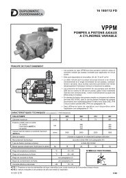
MOUNTING INTERFACE<br />
OPERATING PRINCIPLE<br />
ISO 4401-05-04-0-05<br />
(CETOP 4.2-4-05-320)<br />
P<br />
T<br />
54<br />
50.8<br />
37.3<br />
27<br />
46<br />
32.5<br />
21.4<br />
6.3<br />
16.7<br />
3.2<br />
T<br />
P<br />
A<br />
B<br />
M6<br />
P1<br />
T1<br />
— The Z4M valve is a piloted pressure reducing valve made<br />
as a modular version with mounting surface according to<br />
the ISO 4401 (CETOP PR 121H) standards.<br />
— It is used to reduce pressure on secondary circuit<br />
branches, assuring stability of the controlled pressure and<br />
even changing the flow that runs through the valve.<br />
Ø11.2 (max)<br />
— It can be assembled quickly under the ISO 4401-05<br />
(CETOP 05) directional solenoid valves without use of<br />
pipes.<br />
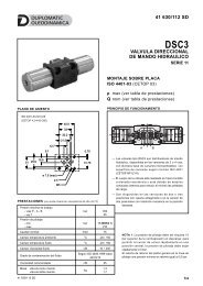
CONFIGURATIONS (see hydraulic symbols table)<br />
— Z4M*-I: pressure reduction on line P - drainage connected to line T.<br />
— Z4M*-A: pressure reduction on line A and full pressure on line B.<br />
— Z4M*-B: pressure reduction on line B and full pressure on line A.<br />
PERFORMANCES (measured with mineral oil of viscosity 36cSt at 50°C)<br />
Maximum operating pressure bar 320<br />
— It is normally supplied with a countersunk hex adjustment<br />
screw, locking nut and maximum adjustment travel<br />
limiting device.<br />
— It is available in four different pressure adjustment ranges<br />
up to 320 bar.<br />
HYDRAULIC SYMBOLS<br />
Z4M*-I PT AB<br />
M<br />
Maximum flow rate in the controlled line P<br />
Maximum flow rate in the free lines<br />
Drainage flow rate<br />
l/min<br />
80<br />
100<br />
≤ 0,07<br />
Ambient temperature range °C -20 / +50<br />
Z4M*-A<br />
M<br />
P1 T1<br />
PT<br />
A1 B1<br />
AB<br />
Fluid temperature range °C -20 / +80<br />
Fluid viscosity range cSt 10 ÷ 400<br />
P1 T1<br />
A1 B1<br />
Fluid contamination degree<br />
According to ISO 4406:1999<br />
class 20/18/15<br />
Z4M*-B<br />
M<br />
PT<br />
AB<br />
Recommended viscosity cSt 25<br />
Mass kg 2,7<br />
P1 T1<br />
A1 B1<br />
<strong>62</strong> <strong>300</strong>/<strong>110</strong> <strong>ED</strong> 1/2
Z4M<br />
SERIES 50<br />
1 - IDENTIFICATION CODE<br />
Z 4 M - / / 50 /<br />
Pressure reducing valve<br />
Size: ISO 4401-05 (CETOP 05)<br />
Modular version<br />
Pressure adjustment range:<br />
3 = 5 ÷ 70 bar<br />
4 = 8 ÷ 140 bar<br />
5 = 10 ÷ 210 bar<br />
6 = 15 ÷ 320 bar<br />
Seals: omit for mineral oils<br />
V = viton for special fluids<br />
Series No. (the overall and mounting<br />
dimensions remain unchanged from 50 to 59)<br />
M1 = Adjustment knob<br />
(omit for adjustment with countersunk hex screw)<br />
Configurations: I: pressure reduction on line P. Internal drainage connected to line T<br />
A: pressure reduction on line A and full pressure on line B<br />
B: pressure reduction on line B and full pressure on line A<br />
2 - CHARACTERISTIC CURVES (values obtained with viscosity of 36 cSt at 50°C)<br />
ADJUSTMENT<br />
<strong>PRESSURE</strong> DROPS ∆p - Q<br />
1) pressure drops<br />
P 1 →P<br />
2) pressure drops<br />
on free lines<br />
(ex. A→A 1 )<br />
3 - HYDRAULIC FLUIDS<br />
Use mineral oil-based hydraulic fluids HL or HM type, according to ISO 6743-4. For these fluids, use NBR seals. For fluids HFDR type<br />
(phosphate esters) use FPM seals (code V). For the use of other kinds of fluid such as HFA, HFB, HFC, please consult our technical<br />
department. Using fluids at temperatures higher than 80 °C causes a faster degradation of the fluid and of the seals characteristics.<br />
The fluid must be preserved in its physical and chemical characteristics.<br />
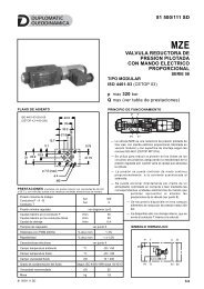
4 - OVERALL AND MOUNTING DIMENSIONS<br />
4<br />
1<br />
2<br />
dimensions in mm<br />
25<br />
66<br />
72<br />
26<br />
50<br />
23.5<br />
3<br />
1 Locking nut<br />
spanner 17<br />
2 Countersunk hex<br />
adjustment screw:<br />
Spanner 5.<br />
Rotate clockwise to<br />
increase pressure<br />
5<br />
ø32<br />
70<br />
12<br />
T<br />
P<br />
A B<br />
T<br />
117<br />
185<br />
50<br />
3 Mounting surface<br />
with sealing rings:<br />
5 OR type 2050<br />
(12.42x1.78)<br />
90 Shore<br />
4 Pressure gauge port<br />
1/4” BSP<br />
DUPLOMATIC OLEODINAMICA S.p.A.<br />
20015 PARABIAGO (MI) • Via M. Re Depaolini 24<br />
Tel. +39 0331.895.111<br />
Fax +39 0331.895.339<br />
www.duplomatic.com • e-mail: sales.exp@duplomatic.com<br />
<strong>62</strong> <strong>300</strong>/<strong>110</strong> <strong>ED</strong> REPRODUCTION IS FORBIDDEN. THE COMPANY RESERVES THE RIGHT TO APPLY ANY MODIFICATIONS.<br />
2/2