Vitoplex 200 datasheet - Viessmann
Vitoplex 200 datasheet - Viessmann
Vitoplex 200 datasheet - Viessmann

Create successful ePaper yourself
Turn your PDF publications into a flip-book with our unique Google optimized e-Paper software.
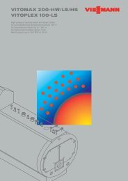
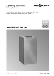
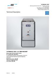
VIESMANN VITOPLEX <strong>200</strong><br />
Low temperature oil/gas boiler<br />
700 to 1950 kW<br />
Datasheet<br />
Part no. and prices: see pricelist<br />
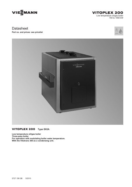
VITOPLEX <strong>200</strong> Type SX2A<br />
Low temperature oil/gas boiler<br />
Three-pass boiler<br />
For operation with modulating boiler water temperature.<br />
With the Vitotrans 300 as a condensing unit.<br />
5727 158 GB 5/2010
Benefits at a glance<br />
■ Economical and environmentally responsible through modulating<br />
boiler water temperature.<br />
■ Standard seasonal efficiency [to DIN] for operation with fuel oil: 89<br />
% (H s )/95 % (H i ).<br />
■ Optional stainless steel flue gas/water heat exchanger for higher<br />
standard seasonal efficiency [to DIN] through condensing technology.<br />
■ Three-pass boiler with low combustion chamber loading, resulting in<br />
clean combustion with low emissions.<br />
■ Wide water galleries and large water content provide excellent natural<br />
circulation and safe heat transfer.<br />
■ Long burner runtimes and fewer cycle intervals, due to large water<br />
content, protect the environment.<br />
■ Compact design for easy transportation – important for modernisation<br />
projects.<br />
■ Economical and safe operation of the heating system through the<br />
digital Vitotronic control system with communication capability.<br />
Standardised LON BUS for complete integration into building management<br />
systems.<br />
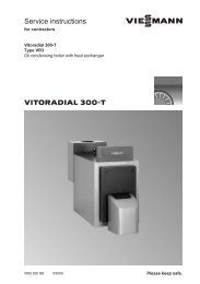
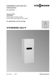
A Highly effective thermal insulation<br />
B Second hot gas flue<br />
C Third hot gas flue<br />
D Water deflector with return injectors<br />
E Combustion chamber (first pass)<br />
F Boiler door<br />
5727 158 GB<br />
2 VIESMANN VITOPLEX <strong>200</strong>
5727 158 GB<br />
Boiler specification<br />
Specification<br />
Rated heating output kW 700 900 1100 1300 1600 1950<br />
Rated heat input kW 761 978 1196 1413 1739 2120<br />
CE designation<br />
CE-0085BQ0020<br />
in accordance with the Gas Appliances<br />
Directive<br />
Permissible flow temperature °C 110 (to 120 °C on request)<br />
(= safety temperature)<br />
Permiss. operating temperature °C 95<br />
Permiss. operating pressure bar 6<br />
Hot gas pressure drop Pa 270 460 400 570 530 850<br />
mbar 2.7 4.6 4.0 5.7 6.5 8.5<br />
Boiler body dimensions<br />
Length (dim. k) *1 mm 2<strong>200</strong> 2500 2450 2670 3075 3075<br />
Width (dim. c) mm 1085 1085 1180 1180 1280 1280<br />
Height (incl. connectors) (dim. e) mm 1670 1670 1900 1900 2120 2120<br />
Overall dimensions<br />
Total length (dim. f) mm 2510 2610 2560 2780 3205 3205<br />
Total width<br />
– with control unit (dim. a) mm 1460 1460 1555 1555 1660 1660<br />
– without control unit (dim. b) mm 1285 1285 1380 1380 1485 1485<br />
Total height (incl. lifting eyes) (dim. mm 1690 1690 1920 1920 2140 2140<br />
h)<br />
Height of anti-vibration boiler supports<br />
mm 37 37 37 37 37 37<br />
(loaded)<br />
Foundations<br />
Length mm 1900 2<strong>200</strong> 2150 2300 2700 2700<br />
Width mm 1<strong>200</strong> 1<strong>200</strong> 1300 1300 1400 1400<br />
Combustion chamber diameter mm 620 620 720 720 840 840<br />
Combustion chamber length mm 1700 <strong>200</strong>0 1930 2150 2530 2530<br />
Weight boiler body kg 1525 1655 2150 2330 3030 3190<br />
Total weight kg 1640 1780 2285 2475 3210 3370<br />
Boiler with thermal insulation and<br />
boiler control unit<br />
Content boiler water litres 935 1325 1525 1690 2510 2420<br />
Boiler connections<br />
Boiler flow and return PN 6 DN 100 100 125 125 150 150<br />
Safety connection (safety valve) PN 16 DN 50 50 65 65 65 65<br />
Drain R (external) 1¼ 1¼ 1¼ 1¼ 1¼ 1¼<br />
Flue gas parameters *2<br />
Temperature (at boiler water temperature<br />
60 °C)<br />
– at rated output °C 180<br />
– at partial load °C 125<br />
Temperature (at boiler water temperature<br />
°C 195<br />
80 °C)<br />
Flue gas mass flow rate<br />
– for natural gas kg/h 1.5225 x combustion output in kW<br />
– for fuel oil EL kg/h 1.5 x combustion output in kW<br />
Required draught Pa/mbar 0<br />
Flue outlet Ø mm 300 300 350 350 400 400<br />
Total gas capacity<br />
m 3 0.90 1.00 1.35 1.45 2.50 2.50<br />
Combustion chamber, hot gas<br />
flues, return pipes, reversal and<br />
flue gas box<br />
Standard seasonal efficiency [to %<br />
DIN]<br />
(for operation with fuel oil)<br />
at heating system temp. 75/60 °C 89 (H s )/95 (H i )<br />
Standby loss q B,70 % 0.15 0.13 0.13 0.12 0.13 0.11<br />
Matching Vitotrans 300<br />
– Gas operation Part no. Z007 212 Z007 213 Z007 214<br />
– Oil operation Part no. Z007 215 Z007 216 Z007 217<br />
*1 Boiler door removed.<br />
*2 Values for calculating the size of the flue system to EN 13384 relative to 13.2 % CO 2 for fuel oil EL and 10 % CO 2 for natural gas.<br />
Flue gas temperatures measured as gross values at 20 °C combustion air temperature.<br />
The details for partial load refer to 60% of the rated output. Calculate the flue gas mass flow rate accordingly when the partial load differs<br />
from that stated (subject to operating mode).<br />
VITOPLEX <strong>200</strong> VIESMANN 3
i<br />
Boiler specification (cont.)<br />
Rated heating output kW 700 900 1100 1300 1600 1950<br />
Rated heating output<br />
Boiler with Vitotrans 300<br />
– Gas operation kW 773.5 994.5 1215.0 1436.0 1768.0 2154.0<br />
– Oil operation kW 750.0 964.0 1179.0 1393.0 1715.0 2090.0<br />
CE designation CE-0085BS0287<br />
Vitotrans 300 in conjunction with a<br />
boiler as a condensing unit<br />
Hot gas pressure drop<br />
Pa 320 540 520 730 640 1010<br />
Boiler with Vitotrans 300<br />
mbar 3.2 5.4 5.2 7.3 6.4 10.1<br />
Total length<br />
Boiler with Vitotrans 300<br />
without burner<br />
mm 3820 4120 3670 3890 4140 4470<br />
Dimensions<br />
k<br />
DB<br />
KR<br />
SA<br />
l<br />
RG<br />
n<br />
360<br />
KV<br />
m<br />
KAB<br />
AGS<br />
KTÜ<br />
TSA<br />
KTS<br />
R<br />
AGA<br />
R<br />
KRG<br />
d<br />
e<br />
h<br />
SCH<br />
o<br />
135<br />
KOA<br />
a<br />
c<br />
b<br />
145<br />
g<br />
f<br />
108<br />
E<br />
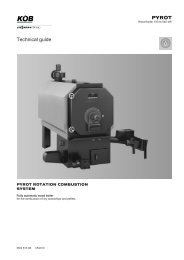
AGA Flue outlet<br />
AGS Female connection for flue gas temperature sensor (R ½)<br />
DB Female connection for maximum pressure limiter (R ½)<br />
E Drain<br />
KAB Boiler cover, walk-on<br />
KOA Condensate drain<br />
KR Boiler return<br />
KRG Boiler control unit<br />
KTS Boiler water temperature sensor (shown offset)<br />
KTÜ Boiler door<br />
KV Boiler flow<br />
R Cleaning aperture<br />
RG Female connection for additional control equipment (R ½)<br />
SA Safety connection (safety valve)<br />
SCH Inspection aperture<br />
Dimensions<br />
Rated heating output kW 700 900 1100 1300 1600 1950<br />
a mm 1460 1460 1555 1555 1660 1660<br />
b mm 1285 1285 1380 1380 1485 1485<br />
c mm 1085 1085 1180 1180 1280 1280<br />
d mm 1590 1590 1815 1815 2035 2035<br />
e mm 1670 1670 1900 1900 2120 2120<br />
f mm 2510 2610 2560 2780 3205 3205<br />
g (length of the base rails) mm 1775 2075 <strong>200</strong>5 2225 2610 2610<br />
h mm 1690 1690 1920 1920 2140 2140<br />
i mm 525 525 580 580 640 640<br />
k (transport dimension) mm 2<strong>200</strong> 2500 2450 2670 3075 3075<br />
l mm 1420 1720 1650 1870 2250 2250<br />
m mm 280 280 300 300 320 320<br />
n mm 890 1040 1005 1115 1305 1305<br />
o mm 1270 1270 1480 1480 1690 1690<br />
4 VIESMANN VITOPLEX <strong>200</strong><br />
5727 158 GB
Boiler specification (cont.)<br />
Dimension k: Boiler door removed<br />
Installation<br />
Minimum clearances<br />
<strong>200</strong> (100)<br />
b<br />
To enable convenient installation and maintenance, observe the stated<br />
clearance dimensions; maintain the minimum clearances where<br />
space is tight (dimensions in brackets). In the delivered condition, the<br />
boiler door opens to the right. You can reposition the hinge bolts so<br />
that the door can open to the left.<br />
800<br />
(50)<br />
a<br />
400<br />
(300)<br />
500<br />
(50)<br />
A Boiler<br />
B Burner<br />
C Anti-vibration boiler supports<br />
D Boiler control unit<br />
Dimensions<br />
Rated kW 700 900 1100 1300 1600 1950<br />
heating<br />
output<br />
a mm <strong>200</strong>0 <strong>200</strong>0 2<strong>200</strong> 2400 2900 2900<br />
b mm Burner length (installed)<br />
Installation conditions<br />
■ Avoid air contamination through halogenated hydrocarbons (e.g. as<br />
in sprays, paints, solvents and cleaning agents)<br />
■ Avoid very dusty conditions<br />
■ Avoid high levels of humidity<br />
■ Prevent frost damage and ensure good ventilation<br />
Dim. a:<br />
This space in front of the boiler is required to enable the<br />
cleaning of the hot gas flues.<br />
The 800 mm clearance between the individual boilers can be reduced<br />
to 50 mm, if the control units are fitted to the opposite sides of the<br />
boiler.<br />
Otherwise, the system may suffer faults and damage.<br />
In rooms where air contamination through halogenated hydrocarbons<br />
may occur, install the boiler only if adequate measures can be<br />
taken to provide a supply of uncontaminated combustion air.<br />
Burner installation<br />
Install the burner plate supplied on the hinged boiler door.<br />
The burner must be fitted to the burner plate; installations without a<br />
burner plate, immediately onto the boiler door, are not possible.<br />
Drill the burner plate supplied on site in accordance with the burner<br />
dimensions.<br />
Burner plates may be factory-fitted on request (chargeable option). For<br />
this, please state the burner make and type when ordering.<br />
The blast tube must protrude through the thermal insulation on the<br />
boiler door.<br />
5727 158 GB<br />
VITOPLEX <strong>200</strong> VIESMANN 5
Boiler specification (cont.)<br />
e<br />
d<br />
a<br />
f<br />
c<br />
b<br />
g<br />
h<br />
Dimensions<br />
Rated kW 700 900 1100 1300 1600 1950<br />
heating<br />
output<br />
a 7mm 350 350 400 400 400 400<br />
b 7mm 400 400 490 490 490 490<br />
c Number/<br />
6/M12<br />
thread<br />
d mm 525 525 580 580 640 640<br />
e mm 785 785 885 885 970 970<br />
f ° 15 15 30 30 30 30<br />
g mm 75 75 75 75 75 75<br />
h mm 150 150 150 150 170 170<br />
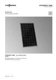
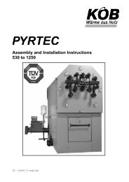
Pressure drop on the heating water side<br />
AB<br />
C<br />
<strong>Vitoplex</strong> <strong>200</strong> is only suitable for fully pumped hot water heating systems.<br />
100<br />
80<br />
60<br />
50<br />
40<br />
30<br />
20<br />
Pressure drop in mbar<br />
10<br />
8<br />
6<br />
5<br />
4<br />
3<br />
2<br />
1<br />
3<br />
4 5 6 8 10 20 30<br />
Flow rate in m³/h<br />
50 80 150<br />
40 60 100<br />
A Rated output 700 and 900 kW<br />
B Rated output 1100 and 1300 kW<br />
C Rated output 1600 and 1950 kW<br />
5727 158 GB<br />
6 VIESMANN VITOPLEX <strong>200</strong>
Vitotrans 300 specification<br />
Specification<br />
Vitotrans 300<br />
– Gas operation Part no. Z007 212 Z007 213 Z007 214<br />
– Oil operation Part no. Z007 215 Z007 216 Z007 217<br />
Rated boiler output kW 620-900 630-1300 1600-<strong>200</strong>0<br />
Rated output of the Vitotrans 300<br />
for<br />
– Gas operation from kW 62.0 63.0 160.0<br />
to kW 94.5 136.0 204.0<br />
– Oil operation from kW 43.0 44.0 115.0<br />
to kW 64.0 93.0 140.0<br />
Permiss. operating pressure bar 6<br />
Permissible flow temperature °C 110<br />
(= safety temperature)<br />
Hot gas pressure drop Pa 40-80 40-160 100-175<br />
mbar 0.4-0.8 0.4-1.6 1.0-1.75<br />
Flue gas mass flow rate from kg/h 1010 1057 2670<br />
to kg/h 1500 2160 3300<br />
Overall dimensions<br />
Total length (dim. f) mm 1046 1<strong>200</strong><br />
Total width (dimension m), incl. mating mm 1097 1226<br />
flanges<br />
Total height (dimension i) mm 1783 2024<br />
Transport dimensions<br />
Length (dimension f) mm 1046 1<strong>200</strong><br />
Width (dimension m), excl. mating mm 989 1112<br />
flange<br />
Height (dimension a) mm 1674 1915<br />
Total weight heat exchanger incl. thermal<br />
kg 355 470<br />
insulation<br />
Contents<br />
Heating water litres 215 295<br />
Flue gas m 3 0.336 0.544<br />
Connections<br />
Heating water flow and return PN 16 DN 100 125<br />
Condensate drain 7 mm 32<br />
Flue gas connection NW 300 350<br />
Rated output range of the Vitotrans 300 and flue gas temperature<br />
Output of the Vitotrans 300 for a flue gas cooling during gas operation<br />
of <strong>200</strong>/65 °C, during oil operation of <strong>200</strong>/70 °C and a heating water<br />
temperature rise in the Vitotrans 300 of 40 °C to 42.5 °C.<br />
For conversion to other temperatures, see chapter "Output data".<br />
Approved quality<br />
CE designation according to current EC Directives at a permissible<br />
flow temperature (safety temperature) of up to 110 °C to<br />
EN 12828.<br />
Hot gas pressure drop<br />
Hot gas pressure drop at rated output. The burner must be able to<br />
overcome the hot gas pressure drop of the boiler, the Vitotrans 300<br />
and the flue pipe.<br />
5727 158 GB<br />
VITOPLEX <strong>200</strong> VIESMANN 7
Dimensions<br />
B<br />
A<br />
b<br />
c<br />
d<br />
h<br />
a<br />
l<br />
i<br />
Vitotrans 300 specification (cont.)<br />
HV<br />
E<br />
HR<br />
n<br />
Rg<br />
AGA<br />
R<br />
KOA<br />
k<br />
e f m<br />
A<br />
B<br />
Connection collar<br />
Offset flue adaptor (only for Z007 212 and Z007 215 for <strong>Vitoplex</strong><br />
boilers)<br />
AGA Flue outlet<br />
E Drain connector<br />
HR Heating water return (inlet)<br />
HV Heating water flow (outlet)<br />
KOA Condensate drain<br />
R Cleaning aperture<br />
Dimensions<br />
Part no. Z007 212 Z007 213 Z007 214<br />
Z007 215 Z007 216 Z007 217<br />
a mm 1674 1674 1915<br />
b mm 1270 1480 1690<br />
c mm 1480 1480 1690<br />
d mm 116 116 206<br />
e mm 420 15 15<br />
f mm 1046 1046 1<strong>200</strong><br />
g (internal) 7 mm 301 301 352<br />
h mm 321 321 446<br />
i mm 1783 1783 2024<br />
k mm 476 476 670<br />
l mm 375 375 559<br />
m mm 989 989 1112<br />
n mm 1215 1215 1387<br />
Delivered condition<br />
Heat exchanger body with fitted flue gas header and integral feet.<br />
Mating flanges and screws are fitted to the connector.<br />
1 Carton with thermal insulation for flue gas/water heat exchanger<br />
1 Carton with collar<br />
1 Crate with offset flue adaptor<br />
1 Carton with thermal insulation for offset flue adaptor<br />
5727 158 GB<br />
8 VIESMANN VITOPLEX <strong>200</strong>
Vitotrans 300 specification (cont.)<br />
Pressure drop on the heating water side<br />
Part no. Z007 212 to Z007 217<br />
100<br />
90 80<br />
70<br />
40<br />
30<br />
20<br />
Part no.<br />
Z007 212<br />
Z007 213<br />
Z007 215<br />
Z007 216<br />
Z007 214<br />
Z007 217<br />
Curve<br />
E<br />
F<br />
50 60 5<br />
6<br />
8<br />
10<br />
20<br />
30<br />
40<br />
50<br />
60<br />
80<br />
100<br />
Pressure drop in mbar<br />
10 9<br />
8 7<br />
6 5<br />
4<br />
3<br />
2<br />
1<br />
Flow rate in m³/h<br />
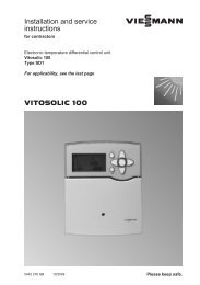
Output data<br />
Vitotrans 300 for gas operation<br />
1.4<br />
Conversion factor<br />
1.2<br />
1<br />
0.8<br />
0.6<br />
0.4<br />
A<br />
B<br />
75 70 65 60 55 50 45 40 35 30 25 20<br />
Heating water inlet temperature in °C<br />
A Flue gas inlet temperature <strong>200</strong> °C<br />
B Flue gas inlet temperature 180 °C<br />
Conversion of the output data<br />
The output data of the Vitotrans 300 flue gas/water heat exchanger<br />
refers to a flue gas inlet temperature of <strong>200</strong> °C and a heating water<br />
inlet temperature into the heat exchanger of 40 °C.<br />
For different conditions the output can be calculated by multiplying the<br />
given rated output by the conversion factor established from the diagram.<br />
Boiler delivered condition<br />
5727 158 GB<br />
Boiler body with fitted boiler door, fitted cleaning cover and permanently<br />
fitted boiler cover.<br />
Mating flanges are fitted to all the connectors.<br />
Adjustable feet and burner plate are supplied in the combustion chamber.<br />
2 Cardboard boxes with thermal insulation and 1 cleaning brush<br />
1 Cardboard box containing the boiler control unit and 1 bag with<br />
technical documentation<br />
1 Product pack (boiler coding card and technical documentation)<br />
VITOPLEX <strong>200</strong> VIESMANN 9
Boiler delivered condition (cont.)<br />
Control unit versions<br />
For single boiler systems:<br />
■ without Vitocontrol control panel<br />
Vitotronic 100 (type GC1)<br />
for operation with a constant boiler water temperature or for weathercompensated<br />
operation in conjunction with a control panel (see<br />
below) or an external control unit.<br />
Vitotronic <strong>200</strong> (type GW1)<br />
for modulating boiler water temperature without mixer control<br />
Vitotronic 300 (type GW2)<br />
for modulating boiler water temperature, with mixer control for up to<br />
2 heating circuits with mixer<br />
■ with Vitocontrol control panel<br />
Vitotronic 100 (type GC1) and LON module (accessories)<br />
and<br />
Vitocontrol control panel with Vitotronic 300-K (type MW1S) for<br />
weather-compensated operation and mixer control for up to 2 heating<br />
circuits with mixer and additional Vitotronic <strong>200</strong>-H, type HK1S or<br />
HK3S for 1 or up to 3 heating circuits with mixer<br />
or<br />
Control panel with external control unit (on site)<br />
For multi-boiler systems (up to 4 boilers):<br />
■ without Vitocontrol control panel<br />
Vitotronic 100 (type GC1) and LON module in conjunction with<br />
Vitotronic 300-K (type MW1)<br />
for modulating boiler water temperature (one boiler is supplied with<br />
the standard controls for a multi-boiler system)<br />
and<br />
Vitotronic 100 (type GC1) and LON module for modulating boiler<br />
water temperature for every additional boiler in a multi-boiler system<br />
■ with Vitocontrol control panel<br />
Vitotronic 100 (type GC1) and LON module for modulating boiler<br />
water temperature for every additional boiler in a multi-boiler system<br />
and<br />
Vitocontrol control panel with the Vitotronic 300-K (type MW1S)<br />
for multi-boiler system, weather-compensated operation and mixer<br />
control for a max. of 2 heating circuits with mixer and additional<br />
Vitotronic <strong>200</strong>-H, type HK1S or HK3S for 1 or up to 3 heating circuits<br />
with mixer<br />
or<br />
Control panel with external control unit (on site)<br />
Boiler accessories<br />
See pricelist and "Boiler accessories" <strong>datasheet</strong>.<br />
Operating conditions with Vitotronic boiler control units<br />
For water quality requirements, see the technical guide to this boiler<br />
40 °C – Oil operation 53 °C<br />
Requirements<br />
Operation with burner load ≥ 60 % < 60 %<br />
1. Heating water flow rate None<br />
2. Boiler return temperature (minimum – Oil operation<br />
value) *3 – Gas operation 53 °C – Gas operation 58 °C<br />
3. Lower boiler water temperature – Oil operation 50 °C – Oil operation 60 °C<br />
– Gas operation 60 °C – Gas operation 65 °C<br />
4. Two-stage burner operation Stage 1 60 % of rated output No minimum load required<br />
5. Modulating burner operation Between 60 and 100 % of rated output No minimum load required<br />
6. Reduced mode Single boiler systems and lead boiler of multi-boiler systems<br />
– Operation with the lower boiler water temperature<br />
Lag boilers of multi-boiler systems<br />
– Can be shut down<br />
7. Weekend setback As per reduced mode<br />
Notes<br />
Installation of a suitable burner<br />
Delivery without burner.<br />
Matching pressure-jet oil/gas burners are available separately from<br />
Weishaupt or ELCO (see pricelist). Delivery direct from Weishaupt or<br />
ELCO.<br />
The material of the burner head must be suitable for operating temperatures<br />
of at least 500 °C.<br />
Pressure-jet oil burner<br />
The burner must be tested and designated to EN 267.<br />
Pressure-jet gas burner<br />
The burner must be tested to EN 676 and CE-designated in accordance<br />
with Directive <strong>200</strong>9/142/EC.<br />
Burner adjustment<br />
Adjust the oil or gas throughput of the burner to suit the rated boiler<br />
output.<br />
*3 The technical guide (system examples) contains a relevant system example for the installation of a return temperature raising facility.<br />
5727 158 GB<br />
10 VIESMANN VITOPLEX <strong>200</strong>
Notes (cont.)<br />
Permissible flow temperatures<br />
Hot water boilers for permissible flow temperatures (= safety temperatures)<br />
■ to 110 °C<br />
CE designation:<br />
CE-0085 in accordance with the Gas Appliances Directive<br />
■ above 110 °C (up to 120 °C on request)<br />
CE designation:<br />
CE-0035 according to the Pressure Equipment Directive<br />
Additional safety equipment is required for operation with a safety<br />
temperature above 110 °C.<br />
– Boilers with a safety temperature above 110 °C must be supervised<br />
in accordance with the Health & Safety at Work Act [Germany].<br />
In accordance with conformity assessment diagram no.5<br />
of the EU Pressure Equipment Directive, these boilers must be<br />
categorised as class IV.<br />
The system must be tested prior to commissioning.<br />
– Annually – external inspection (inspection of the safety equipment<br />
and the water quality),<br />
– Every three years – internal inspection (as an alternative, a water<br />
pressure test is an option),<br />
– Every nine years – water pressure test (for max. test pressure,<br />
see the type plate).<br />
The test must be carried out by an authorised body (e.g. TÜV [in<br />
Germany]).<br />
Further information on design/engineering<br />
See the technical guide to this boiler.<br />
Approved quality<br />
CE designation according to current EC Directives.<br />
I für Erzeugnisse des Gas- und Wasserfachs.<br />
5727 158 GB<br />
VITOPLEX <strong>200</strong> VIESMANN 11
Printed on environmentally friendly,<br />
chlorine-free bleached paper<br />
Subject to technical modifications.<br />
<strong>Viessmann</strong> Werke GmbH&Co KG<br />
D-35107 Allendorf<br />
Telephone: +49 6452 70-0<br />
Fax: +49 6452 70-2780<br />
www.viessmann.com<br />
<strong>Viessmann</strong> Limited<br />
Hortonwood 30, Telford<br />
Shropshire, TF1 7YP, GB<br />
Telephone: +44 1952 675000<br />
Fax: +44 1952 675040<br />
E-mail: info-uk@viessmann.com<br />
5727 158 GB<br />
12 VIESMANN VITOPLEX <strong>200</strong>