NEXO PS Brochure 2.69MB - Yamaha Commercial Audio
NEXO PS Brochure 2.69MB - Yamaha Commercial Audio
NEXO PS Brochure 2.69MB - Yamaha Commercial Audio

You also want an ePaper? Increase the reach of your titles
YUMPU automatically turns print PDFs into web optimized ePapers that Google loves.
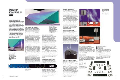
Coverage<br />
According to<br />
Need<br />
For mobile system designs, our<br />
asymmetrical horn design allows users to<br />
quickly change horn coverage according<br />
to need. The specific dispersion of <strong>PS</strong>8,<br />
<strong>PS</strong>10 & <strong>PS</strong>15 horns can be seen on Figure<br />
#1 ("FOH" configuration). Access to any<br />
<strong>PS</strong> horn for inspection and configuration<br />
is easily made by removing the front grille<br />
with a gentle pull on the sides of the grille<br />
to disconnect the press-stud fixings.<br />
To modify horn orientation, remove the<br />
four Allen 4 metric or TORX TX25 screws<br />
(depending on model and age of the<br />
cabinet) that secure the horn.<br />
Figure #2: (Above) With<br />
horn rotated 180° from<br />
Figure #1, this monitor<br />
application provides a<br />
wide (100°) sweet spot for<br />
the performer’s listening<br />
zones, and restricts<br />
unwanted below-the-belt<br />
coverage.<br />
www.nexo-sa.com<br />
Front-of-House Configuration<br />
Good coverage of audiences often requires a<br />
conflicting combination of wide coverage (“shortthrow”)<br />
for the closest listeners (below cabinet<br />
axis) and narrow coverage (“long-throw”) for<br />
distant areas (on or above axis). The <strong>PS</strong> Series<br />
horizontal horn coverage varies from “shortthrow”<br />
to “long-throw” along the vertical axis to<br />
match precisely these practical single system<br />
requirements. In most applications, asymmetrical<br />
horns should be used with the “wide” dispersion<br />
side directed towards the floor (as referenced<br />
by the arrow), but any of the four various horn<br />
orientations are usable, depending on venue<br />
geometry and room acoustics (see Figure #1).<br />
Stage Monitors<br />
For stage monitors, the best coverage must be<br />
wider when performers are closest to the wedge,<br />
and above the horn axis, than when they move<br />
away from the wedge and below the horn axis<br />
(see Figure #2). The flexibility to be deployed in<br />
this manner is one major reason why <strong>PS</strong> Series<br />
loudspeakers are widely used in floor monitor<br />
applications.<br />
In this configuration, the <strong>PS</strong> horn<br />
must be rotated so that its “wide side”<br />
dispersion is in “wedge” position and that the<br />
directional arrow is pointed towards the top of<br />
the horizontally-oriented cabinet. This monitorfriendly<br />
dispersion combines with the <strong>PS</strong> Series’<br />
exceptional power handling to yield unrivalled<br />
foldback/monitor performance.<br />
Photo #1: The <strong>PS</strong>8<br />
TDcontroller<br />
Figure #1: (Above)<br />
Computer representation<br />
of how the <strong>PS</strong> Series’<br />
asymmetrical horns match<br />
pattern control to the<br />
seating area of a typical<br />
rectangular venue.<br />
<strong>PS</strong> Series TD Controllers<br />
Equalization and Subsonic/VHF Filtering<br />
Because all <strong>PS</strong> cabinets are acoustically<br />
designed for maximum efficiency, each TD<br />
Controller applies strategic equalization<br />
corrections to insure proper tonal balance and<br />
system response. This active equalization also<br />
extends <strong>PS</strong> Systems’ bandwidth, especially<br />
at low frequencies where acoustical output<br />
is limited by cabinet size. Active, rather than<br />
passive, attenuation allows amplifier voltages<br />
to be lowered for a specific output SPL, and<br />
functionally increase the maximum possible SPL<br />
from any <strong>PS</strong> amplifier.<br />
Low and high-pass filters are used to<br />
remove signals out of the usable frequency range,<br />
eliminating sub and ultra-sonic components<br />
that could potentially degrade the performance<br />
of the Controller and amplifiers. These filters are<br />
optimized to realize the overall target system<br />
response.<br />
<strong>PS</strong>/LSub Crossover and Servo Control<br />
From input signals summed together, the<br />
resulting mono signal is low-pass filtered to<br />
feed the Sub-bass channel. When the channel<br />
configuration is set to Xover, the L&R main<br />
channel's high-pass filters are switched to<br />
bandpass (filter) signal components below the<br />
crossover frequency. Slopes and other filter<br />
characteristics are optimized using techniques<br />
optimized for the each driver’s specific<br />
acoustical data.<br />
VCAs, VCEQs and Amplifiers<br />
Each of the three <strong>Audio</strong> channels (Left, Right<br />
and Sub-bass) contains two voltage-controlled<br />
elements driven by servo signals. The <strong>PS</strong>8Amp<br />
and <strong>PS</strong>10Amp are power amplifiers tailored<br />
for <strong>PS</strong>8 and <strong>PS</strong>10 systems and their respective<br />
LS400-SUB & LS500-SUB sub-bass requirements.<br />
The identical structure and power<br />
ofthese 3RU devices offers two or three-channel<br />
instantaneous configuration via front-panel switch,<br />
allowing 3-way use with the appropriate <strong>NEXO</strong><br />
SubBass or a wideband (2-way) configuration.<br />
Power delivered by the amplifier is<br />
thus optimized for the proper configuration. All<br />
connections and controls are located on the<br />
front panel including mains fuses and voltage<br />
selection. Speaker wiring of each cabinet is<br />
automatically re-assigned.<br />
<strong>PS</strong> Series Rigging and Flying<br />
<strong>PS</strong>8, <strong>PS</strong>10 and <strong>PS</strong>15 have a built-in 35mm (1<br />
3/8in) diameter stand adapter. Cabinets can<br />
be positioned directly on a general-purpose<br />
speaker stand or mast inserted in top-fitted stand<br />
adapters on LS400-SUB, LS500-SUB & LS1200-<br />
SUB models. A U-Coupler accessory allows<br />
relative rotation of two side-by-side cabinets on<br />
top of the mast or on a speaker stand. <strong>PS</strong>8 and<br />
<strong>PS</strong>10 mast and U-couplers are optional. For safety<br />
reasons, U-coupler use is not recommended with<br />
<strong>PS</strong>15 cabinets (see Figuress #1, & #2).<br />
<strong>PS</strong>10 & <strong>PS</strong>15 Flying Rails & Rings<br />
<strong>PS</strong>10s and <strong>PS</strong>15s ship with steel anchor plates<br />
intended for these optional fittings:<br />
■ Top: 6-position aircraft-flying rail. (9 for <strong>PS</strong>15)<br />
■ Bottom: Twin single-position round aircraft<br />
flying rails, or two 3-position aircraft flying<br />
rails for the <strong>PS</strong>15. These rails are supplied with<br />
optional flying kits containing all necessary<br />
screws and four single stud aircraft flying<br />
rings. Heavy-duty double stud flying rings can<br />
be used in all rails except on the <strong>PS</strong>10 bottom.<br />
Vertical orientation of cabinets is a function<br />
of top-rail ring position. For safety reasons<br />
two rings must be linked, per rail, to two<br />
independently fixed straps.<br />
<strong>PS</strong>10 Omnimount® Style Clamps<br />
The back and bottom of the <strong>PS</strong>10 is equipped<br />
with internal M8 metric anchor points for<br />
Omnimount100 Series standard spacing. This is<br />
particularly convenient for permanently installed<br />
cabinets. Original screw removal requires a N°4<br />
metric Allen key/TORX25.<br />
<strong>PS</strong>8 Accessories<br />
There are three <strong>PS</strong>8 mounting accessories. The<br />
FS0081-001 is intended for direct mounting onto<br />
the <strong>PS</strong>8 cabinet surface. It provides two M10<br />
captive nuts that allow these three accessories<br />
to be fitted:<br />
Photo #2 (Above left):<br />
Installed, flown <strong>PS</strong>10<br />
Loudspeaker<br />
Photo #3 (right): The<br />
<strong>PS</strong>15 (accessory) rigging<br />
kit, part # FLY<strong>PS</strong>15<br />
Figure #1(left): <strong>PS</strong> Series<br />
stage rigging facing Front<br />
of House.<br />
Figure #2 (below left):<br />
<strong>PS</strong> Series rigging from the<br />
Performer’s perspective.<br />
■ Standard lighting hook/CLAMP<br />
■ M10 lifting eye bolt<br />
■ DIN Pivot (TV spigot)<br />
The FS0081-002, which must be used with the<br />
FS0081-001, provides two welded M5 nuts and<br />
one welded M10 nut. This adapter allows the<br />
cabinet to be fixed on the wall, ceiling, or on a<br />
stand using the FS0081-003.<br />
The FS0081-003 allows for Horizontal<br />
Cabinet mounting on a stand or a 35mm mast.<br />
It can be used with other accessories or fitted<br />
directly to the cabinet.