Autel Maxiscan Jp701 Manual.pdf - Car Diagnostic Tool
Autel Maxiscan Jp701 Manual.pdf - Car Diagnostic Tool
Autel Maxiscan Jp701 Manual.pdf - Car Diagnostic Tool

Create successful ePaper yourself
Turn your PDF publications into a flip-book with our unique Google optimized e-Paper software.
www.vtoolshop.com<br />
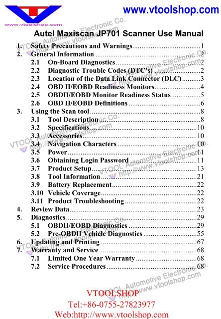
<strong>Autel</strong> <strong>Maxiscan</strong> JP701 Scanner Use <strong>Manual</strong><br />
1. Safety Precautions and Warnings.....................................1<br />
2. General Information .........................................................2<br />
2.1 On-Board <strong>Diagnostic</strong>s..............................................2<br />
2.2 <strong>Diagnostic</strong> Trouble Codes (DTC’s) .........................2<br />
2.3 Location of the Data Link Connector (DLC)..........3<br />
2.4 OBD II/EOBD Readiness Monitors.........................4<br />
2.5 OBDII/EOBD Monitor Readiness Status................5<br />
2.6 OBD II/EOBD Definitions .......................................6<br />
3. Using the Scan tool............................................................8<br />
3.1 <strong>Tool</strong> Description.......................................................8<br />
3.2 Specifications..........................................................10<br />
3.3 Accessories..............................................................10<br />
3.4 Navigation Characters ...........................................10<br />
3.5 Power......................................................................11<br />
3.6 Obtaining Login Password ....................................11<br />
3.7 Product Setup.........................................................13<br />
3.8 <strong>Tool</strong> Information....................................................21<br />
3.9 Battery Replacement..............................................22<br />
3.10 Vehicle Coverage....................................................22<br />
3.11 Product Troubleshooting .......................................22<br />
4. Review Data.....................................................................23<br />
5. <strong>Diagnostic</strong>s.......................................................................29<br />
5.1 OBDII/EOBD <strong>Diagnostic</strong>s .....................................29<br />
5.2 Pre-OBDII Vehicle <strong>Diagnostic</strong>s .............................55<br />
6. Updating and Printing ....................................................67<br />
7. Warranty and Service .....................................................68<br />
7.1 Limited One Year Warranty .................................68<br />
7.2 Service Procedures.................................................68<br />
VTOOLSHOP<br />
Tel:+86-0755-27823977<br />
Web:http://www.vtoolshop.com
www.vtoolshop.com<br />
1. Safety Precautions and Warnings<br />
To prevent personal injury or damage to vehicles and/or the scan<br />
tool, read this instruction manual first and observe the following<br />
safety precautions at a minimum whenever working on a vehicle:<br />
• Always perform automotive testing in a safe environment.<br />
• Wear safety eye protection that meets ANSI standards.<br />
• Keep clothing, hair, hands, tools, test equipment, etc. away from<br />
all moving or hot engine parts.<br />
• Operate the vehicle in a well ventilated work area: Exhaust gases<br />
are poisonous.<br />
• Put blocks in front of the drive wheels and never leave the vehicle<br />
unattended while running tests.<br />
• Use extreme caution when working around the ignition coil,<br />
distributor cap, ignition wires and spark plugs. These components<br />
create hazardous voltages when the engine is running.<br />
• Put the transmission in PARK (for automatic transmission) or<br />
NEUTRAL (for manual transmission) and make sure the parking<br />
brake is engaged.<br />
• Keep a fire extinguisher suitable for gasoline/chemical/electrical<br />
fires nearby.<br />
• Don’t connect or disconnect any test equipment while the ignition<br />
is on or the engine is running.<br />
• Keep the scan tool dry, clean, free from oil/water or grease. Use a<br />
mild detergent on a clean cloth to clean the outside of the scan tool,<br />
when necessary.<br />
VTOOLSHOP<br />
1<br />
Tel:+86-0755-27823977<br />
Web:http://www.vtoolshop.com
www.vtoolshop.com<br />
2. General Information<br />
2.1 On-Board <strong>Diagnostic</strong>s<br />
The first generation of On-Board <strong>Diagnostic</strong>s (called OBD I) was<br />
developed by the California Air Resources Board (CARB) and<br />
implemented in 1988 to monitor some of the emission control<br />
components on vehicles. As technology evolved and the desire to<br />
improve the On-Board <strong>Diagnostic</strong> system increased, a new generation of<br />
On-Board <strong>Diagnostic</strong> system was developed. This second generation of<br />
On-Board <strong>Diagnostic</strong> regulations is called "OBD II".<br />
The European version of OBDII is commonly referred to as EOBD and<br />
has protocols developed for the European vehicle market.<br />
The OBD II system is designed to monitor emission control systems<br />
and key engine components by performing either continuous or<br />
periodic tests of specific components and vehicle conditions. When a<br />
problem is detected, the OBD II system turns on a warning lamp (MIL)<br />
on the vehicle instrument panel to alert the driver typically by the<br />
phrase of “Check Engine” or “Service Engine Soon”. The system will<br />
also store important information about the detected malfunction so that<br />
a technician can accurately find and fix the problem. Here below<br />
follow three pieces of such valuable information:<br />
1) Whether the Malfunction Indicator Light (MIL) is<br />
commanded 'on' or 'off';<br />
2) Which, if any, <strong>Diagnostic</strong> Trouble Codes (DTC’s) are stored;<br />
3) Readiness Monitor status.<br />
2.2 <strong>Diagnostic</strong> Trouble Codes (DTC’s)<br />
EOBD/OBD II <strong>Diagnostic</strong> Trouble Codes are codes that are stored by<br />
the on-board computer diagnostic system in response to a problem<br />
found in the vehicle. These codes identify a particular problem area<br />
and are intended to provide you with a guide as to where a fault might<br />
be occurring within a vehicle. OBD II/EOBD <strong>Diagnostic</strong> Trouble<br />
Codes consist of a five-digit alphanumeric code. The first character, a<br />
letter, identifies which control system sets the code. The other four<br />
characters, all numbers, provide additional information on where the<br />
VTOOLSHOP<br />
2<br />
Tel:+86-0755-27823977<br />
Web:http://www.vtoolshop.com
www.vtoolshop.com<br />
DTC originated and the operating conditions that caused it to set. Here<br />
below is an example to illustrate the structure of the digits:<br />
DTC Example<br />
P 0 2 0 2<br />
Systems<br />
B=Body<br />
C=Chassis<br />
P=Powertrain<br />
U=Network<br />
Identifying specific<br />
malfunctioning<br />
section of the<br />
systems<br />
Code Type<br />
Generic (SAE):<br />
P0, P2, P34-P39<br />
B0, B3<br />
C0, C3<br />
U0, U3.<br />
Manufacturer Specific:<br />
P1, P30-p33<br />
B1, B2<br />
C1, C2<br />
U1, U2<br />
Sub-systems<br />
1= Fuel and Air Metering<br />
2= Fuel and Air Metering<br />
3= Ignition System or Engine Misfire<br />
4= Auxiliary Emission Controls<br />
5= Vehicle Speed Control and Idle<br />
Controls<br />
6= Computer Output Circuits<br />
7= Transmission Controls<br />
8= Transmission Controls<br />
2.3 Location of the Data Link Connector (DLC)<br />
The DLC (Data Link Connector or <strong>Diagnostic</strong> Link Connector) is the<br />
standardized 16-cavity connector where diagnostic scan tools interface<br />
with the vehicle's on-board computer. The DLC is usually located 12<br />
inches from the center of the instrument panel (dash), under or around<br />
the driver’s side for most vehicles. If Data Link Connector is not<br />
located under dashboard, a label should be there telling location. For<br />
some Asian and European vehicles, the DLC is located behind the<br />
ashtray and the ashtray must be removed to access the connector. If the<br />
VTOOLSHOP<br />
3<br />
Tel:+86-0755-27823977<br />
Web:http://www.vtoolshop.com
www.vtoolshop.com<br />
DLC cannot be found, refer to the vehicle’s service manual for the<br />
location.<br />
2.4 OBD II/EOBD Readiness Monitors<br />
An important part of a vehicle’s OBDII/EOBD system is the Readiness<br />
Monitors, which are indicators used to find out if all of the emissions<br />
components have been evaluated by the OBDII/EOBD system. They<br />
are running periodic tests on specific systems and components to<br />
ensure that they are performing within allowable limits.<br />
Currently, there are eleven OBD II/EOBD Readiness Monitors (or I/M<br />
Monitors) defined by the U.S. Environmental Protection Agency<br />
(EPA). Not all monitors are supported by all vehicles and the exact<br />
number of monitors in any vehicle depends on the motor vehicle<br />
manufacturer’s emissions control strategy.<br />
Continuous Monitors -- Some of the vehicle components or systems<br />
are continuously tested by the vehicle’s OBD II system, while others<br />
are tested only under specific vehicle operating conditions. The<br />
continuously monitored components listed below are always ready:<br />
1)Misfire<br />
2)Fuel System<br />
3)Comprehensive Components (CCM)<br />
Once the vehicle is running, the OBD II/EOBD system is continuously<br />
checking the above components, monitoring key engine sensors,<br />
watching for engine misfire, and monitoring fuel demands.<br />
VTOOLSHOP<br />
4<br />
Tel:+86-0755-27823977<br />
Web:http://www.vtoolshop.com
Non-Continuous Monitors -- Unlike the continuous monitors, many<br />
emissions and engine system components require the vehicle to be<br />
operated under specific conditions before the monitor is ready. These<br />
monitors are termed non-continuous monitors and are listed below:<br />
1) EGR System<br />
2) O2 Sensors<br />
3) Catalyst<br />
4) Evaporative System<br />
5) O2 Sensor Heater<br />
6) Secondary air<br />
7) Heated Catalyst<br />
8) A/C system<br />
2.5 OBDII/EOBD Monitor Readiness Status<br />
OBD II systems must indicate whether or not the vehicle’s PCM’s<br />
monitor system has completed testing on each component.<br />
Components that have been tested will be reported as “Ready”, or<br />
“Complete”, meaning they have been tested by the OBD II system. The<br />
purpose of recording readiness status is to allow inspectors to<br />
determine if the vehicle’s OBD II system has tested all the components<br />
and/or systems.<br />
The powertrain control module (PCM) sets a monitor to “Ready” or<br />
“Complete” after an appropriate drive cycle has been performed. The<br />
drive cycle that enables a monitor and sets readiness codes to “Ready”<br />
varies for each individual monitor. Once a monitor is set as “Ready” or<br />
“Complete”, it will remain in this state. A number of factors, including<br />
erasing of diagnostic trouble codes (DTC’s) with a scan tool or a<br />
disconnected battery, can result in Readiness Monitors being set to<br />
“Not Ready”. Since the three continuous monitors are constantly<br />
evaluating, they will be reported as “Ready” all of the time. If testing of<br />
a particular supported non-continuous monitor has not been completed,<br />
the monitor status will be reported as “Not Complete” or “Not Ready.”<br />
In order for the OBD monitor system to become ready, the vehicle<br />
should be driven under a variety of normal operating conditions. These<br />
operating conditions may include a mix of highway driving and stop<br />
5
and go, city type driving, and at least one overnight-off period. For<br />
specific information on getting your vehicle’s OBD monitor system<br />
ready, please consult your vehicle owner’s manual.<br />
2.6 OBD II/EOBD Definitions<br />
Powertrain Control Module (PCM) -- EOBD terminology for the<br />
on-board computer that controls engine and drives train.<br />
Malfunction Indicator Light (MIL) -- Malfunction Indicator Light<br />
(Service Engine Soon, Check Engine) is a term used for the light on the<br />
instrument panel. It is to alert the driver and/or the repair technician<br />
that there is a problem with one or more of vehicle's systems and may<br />
cause emissions to exceed federal standards. If the MIL illuminates<br />
with a steady light, it indicates that a problem has been detected and the<br />
vehicle should be serviced as soon as possible. Under certain<br />
conditions, the dashboard light will blink or flash. This indicates a<br />
severe problem and flashing is intended to discourage vehicle<br />
operation. The vehicle onboard diagnostic system can not turn the MIL<br />
off until necessary repairs are completed or the condition no longer<br />
exists.<br />
DTC -- <strong>Diagnostic</strong> Trouble Codes (DTC) that identify which section<br />
of the emission control system has malfunctioned.<br />
Enabling Criteria -- Also termed Enabling Conditions. They are the<br />
vehicle-specific events or conditions that must occur within the engine<br />
before the various monitors will set, or run. Some monitors require<br />
the vehicle to follow a prescribed “drive cycle” routine as part of the<br />
enabling criteria. Drive cycles vary among vehicles and for each<br />
monitor in any particular vehicle.<br />
EOBD Drive Cycle -- A specific mode of vehicle operation that<br />
provides conditions required to set all the readiness monitors<br />
applicable to the vehicle to the “ready” condition. The purpose of<br />
completing an EOBD drive cycle is to force the vehicle to run its<br />
onboard diagnostics. Some form of a drive cycle needs to be performed<br />
after DTC’s have been erased from the PCM’s memory or after the<br />
battery has been disconnected. Running through a vehicle’s complete<br />
drive cycle will “set” the readiness monitors so that future faults can be<br />
detected. Drive cycles vary depending on the vehicle and the monitor<br />
6
www.vtoolshop.com<br />
that needs to be reset. For vehicle specific drive cycle, consult the<br />
vehicle’s Owner’s <strong>Manual</strong>.<br />
Freeze Frame Data -- When an emission-related fault occurs, the<br />
EOBD system not only sets a code but also records a snapshot of the<br />
vehicle operating parameters to help in identifying the problem. This<br />
set of values is referred to as Freeze Frame Data and may include<br />
important engine parameters such as engine RPM, vehicle speed, air<br />
flow, engine load, fuel pressure, fuel trim value, engine coolant<br />
temperature, ignition timing advance, or closed loop status.<br />
VTOOLSHOP<br />
7<br />
Tel:+86-0755-27823977<br />
Web:http://www.vtoolshop.com
www.vtoolshop.com<br />
3. Using the Scan tool<br />
3.1 <strong>Tool</strong> Description<br />
1 LCD DISPLAY -- Indicates test results. Backlit, 128 x 64 pixel<br />
display with contrast adjustment.<br />
VTOOLSHOP<br />
8<br />
Tel:+86-0755-27823977<br />
Web:http://www.vtoolshop.com
234are three function keys that correspond with “buttons” on<br />
screens for executing commands.<br />
2 FUNCTION BUTTON -- Confirms a selection or an action<br />
from a menu, and enters next menu; It is also used to shift between<br />
text and graphic viewing of live data when viewing and playing<br />
back live data.<br />
3 FUNCTIONAL BUTTON -- Saves retrieved data;<br />
Selects/deselects an item when viewing or recording live data; and<br />
plays/stops playing back live data.<br />
4 FUNCTIONAL BUTTON -- Cancels a selection (or action)<br />
from a menu, and returns to previous menu.<br />
5 UP SCROLL BUTTON -- Moves up through menu and<br />
submenu items in menu mode. When a DTC definition covers more<br />
than one screen, moves up through the current screen to previous<br />
screens for additional data. When looking up DTC, it is used to<br />
change value of selected character.<br />
6 DOWN SCROLL BUTTON -- Moves down through menu and<br />
submenu items in menu mode. When a DTC definition covers more<br />
than one screen, moves up through the current screen to previous<br />
screens for additional data. When looking up DTC, it is used to<br />
change value of selected character.<br />
7 LEFT SCROLL BUTTON -- Moves to previous screen, or to<br />
previous character when looking up DTC’s. It is also used to view<br />
previous trouble code when viewing DTC’s.<br />
8 RIGHT SCROLL BUTTON -- Moves to next screen, or to<br />
next character when looking up DTC’s. It is also used to view next<br />
trouble code when viewing DTC’s.<br />
9 HELP BUTTON -- Provides help information when pressed.<br />
10 POWER SWITCH -- Turns on/off the scan tool when powered<br />
by AAA battery, and resets the tool when powered via vehicle<br />
battery.<br />
○11 EXTENSION CABLE -- Connects the scan tool to the vehicle’s<br />
Data Link Connector (DLC) via diagnostic connectors.<br />
9
3.2 Specifications<br />
1) Display: Backlit, 128 x 64 pixel display with contrast adjustment.<br />
2) Operating Temperature: 0 to 60°C (32 to 140 F°).<br />
3) Storage Temperature: -20 to 70°C (-4 to 158 F°).<br />
4) External Power: 6.0 to 21.0 V power provided via vehicle<br />
battery.<br />
5) Internal Power: 6V power provided by four 1.5V batteries.<br />
6) Dimensions:<br />
Length Width Height<br />
210 mm (8.27”) 99 mm (3.90”) 38 mm (1.50”)<br />
7) NW: 1.0 kg (2.2lb), GW: 1.2 kg (2.65lb).<br />
3.3 Accessories<br />
1) User’s <strong>Manual</strong> -- Instructions on tool operations.<br />
2) CD -- Includes user’s manual, update application and etc.<br />
3) Extension cable -- Connects the scan tool to diagnostic<br />
connector.<br />
4) <strong>Diagnostic</strong> Connector -- Provides power to the scan tool and<br />
communicates between the tool and vehicle.<br />
5) USB cable -- Used to upgrade the scan tool, and to upload<br />
retrieved data.<br />
6) <strong>Car</strong>ry case -- A nylon case to store the scan tool when not in use.<br />
7) Four 1.5V batteries -- Supplies power to the scan tool when<br />
disconnected from vehicle DLC.<br />
3.4 Navigation Characters<br />
Characters used to help navigate the scan tool are:<br />
1) “►” -- Indicates current selection.<br />
2) “$” -- Identifies the control module number from which the data<br />
is retrieved.<br />
3) “Graph” -- Indicates graphic information is available.<br />
4) “ ” -- Indicates battery volume when powered by batteries.<br />
10
5) “ ” -- Scroll bar indicates additional information is available on<br />
previous or next screens.<br />
3.5 Power<br />
Internal Battery Power<br />
The scan tool has four 1.5V batteries that provide power for off-car<br />
review and analysis. Press power key to turn on the scan tool.<br />
When the “ ” icon flashes, replace the battery as instructed in<br />
“Battery Replacement” on paragraph 3.9.<br />
• If the scan tool is stored for a long period of time, remove<br />
batteries to prevent battery leakage from damaging battery<br />
compartment.<br />
External Power<br />
External power of the scan tool is provided via the vehicle Data Link<br />
Connector (DLC). Just follow the steps below to turn on the scan tool:<br />
1) Connect the scan tool and diagnostic connector with the<br />
extension cable supplied.<br />
2) Find DLC on vehicle.<br />
• A plastic DLC cover may be found for some vehicles and you<br />
need to remove it before plugging the OBD2 cable.<br />
3) Plug the diagnostic connector to vehicle’s DLC.<br />
3.6 Obtaining Login Password<br />
CAUTION: The login password is used to get access to software<br />
updates and technical supports from manufacturer or distributors’<br />
websites. DO NOT read the password unless you decide to buy the<br />
scan tool.<br />
1) Install four 1.5V batteries and press power key, or connect<br />
the tool to vehicle DLC to power up the scan tool.<br />
2) From Main Menu, use UP/DOWN button to select Login<br />
Password, and press OK button.<br />
11
www.vtoolshop.com<br />
…………. Main Manu … … …..<br />
Review Data<br />
System Setup<br />
<strong>Tool</strong> Information<br />
►Login Password<br />
OK<br />
3) Press OK button to continue.<br />
………….LOGIN PASSWORD…… …..<br />
Do you wish to read<br />
login password?<br />
The password is used<br />
to get access to<br />
software updates and<br />
OK<br />
Back<br />
4) A message prompting you to give up reading the password<br />
comes up.<br />
…………….LOGIN PASSWORD……….<br />
Do you wish to<br />
give up reading<br />
login password?<br />
OK<br />
Back<br />
5) Press Back button to read password.<br />
VTOOLSHOP<br />
12<br />
Tel:+86-0755-27823977<br />
Web:http://www.vtoolshop.com
………….LOGIN PASSWORD… … …..<br />
LOGIN PW: XXXXXXX<br />
Press any key to con.<br />
• If you decide not to read the password, press OK button to<br />
return.<br />
3.7 Product Setup<br />
The scan tool allows you to make the following adjustments and<br />
settings:<br />
1) Language: Selects the desired language.<br />
2) Contrast: Adjusts the contrast of the LCD display.<br />
3) Unit of Measure: Sets the unit of measure to English or Metric.<br />
4) Auto Power-off: Sets automatic power-off time limits.<br />
5) Title Style: Changes display mode between “with title” and<br />
“without title”.<br />
6) Menu Style:Changes selected menu style between “highlighted”<br />
and “normal”.<br />
7) Scroll Style : Changes scroll style between “scroll” and<br />
“normal”.<br />
8) Button Style:Changes button style between “highlighted”<br />
and “normal”<br />
9) Default: Resets the scan tool to factory default settings.<br />
• Settings of the unit will remain until change to the existing<br />
settings is made.<br />
To enter system setup mode<br />
1) Use UP/DOWN button to select System Setup from Main<br />
Menu and press OK button. Follow the instructions to make<br />
adjustments and settings as described in the following setup<br />
options.<br />
13
……………… . .Main Menu……… ……..<br />
Review Data<br />
►System Setup<br />
<strong>Tool</strong> Information<br />
Login Password<br />
OK<br />
Language Setup<br />
• English is the default language.<br />
2) From System Setup menu, use UP/DOWN button to select<br />
Language, and press OK button.<br />
………… .System Setup……………. .<br />
►Language<br />
Contrast<br />
Unit of Measure<br />
Auto Power-off<br />
Title Style<br />
Menu Style<br />
OK<br />
Back<br />
3) Use UP/DOWN button to select the desired language and press<br />
OK button to save your selection and return to previous menu.<br />
……… ……… …Language…… ……. ….<br />
►English<br />
中 文<br />
Español<br />
Deutsch<br />
Français<br />
Dutch<br />
OK<br />
Back<br />
Contrast Adjustment<br />
1) From System Setup menu, use UP/DOWN scroll button to select<br />
Contrast, and press OK button.<br />
14
www.vtoolshop.com<br />
…………… .System Setup…… ……...<br />
Language<br />
►Contrast<br />
Unit of Measure<br />
Auto Power-off<br />
Title Style<br />
Menu Style<br />
OK<br />
Back<br />
2) From Contrast menu, use LEFT/RIGHT scroll button to<br />
decrease or increase contrast.<br />
……… .Contrast……… …<br />
Press<br />
[LEFT] or [RIGHT]<br />
to adjust contrast<br />
OK<br />
Back<br />
3) Press OK button to save your settings and return to previous<br />
menu.<br />
Unit of Measure<br />
• Metric is the default measurement unit.<br />
1) From System Setup menu, use UP/DOWN scroll button to select<br />
Unit of Measure and press OK button.<br />
…………… ..System Setup…… … …….<br />
Language<br />
Contrast<br />
►Unit of Measure<br />
Auto Power-off<br />
Title Style<br />
Menu Style<br />
OK<br />
Back<br />
VTOOLSHOP<br />
15<br />
Tel:+86-0755-27823977<br />
Web:http://www.vtoolshop.com
2) From Unit of Measure menu, use UP/DOWN scroll button to<br />
select the desired unit of measurement.<br />
……………..Unit of Measure<br />
►Metric<br />
English<br />
….…<br />
OK<br />
Back<br />
3) Press OK button to save your selection and return to previous<br />
menu.<br />
Auto Power-off<br />
• The minimum automatic power-off time is 1 minute, and the<br />
maximum is 30 minutes.<br />
• Auto power-off setup can be performed only when the scanner is<br />
powered by AAA batteries.<br />
1) From System Setup menu, use UP/DOWN scroll button to select<br />
Auto Power-off and press OK button.<br />
………… ……System Setup……… ..<br />
Language<br />
Contrast<br />
Unit of Measure<br />
►Auto Power-off<br />
Title Style<br />
Menu Style<br />
OK<br />
Back<br />
2) From Auto Power-off menu, use UP/DOWN button to change<br />
automatic power-off limits.<br />
16
……… Auto Power-off …<br />
3 minute (s)<br />
Press<br />
[UP] or [DOWN]<br />
to adjust time<br />
OK<br />
Back<br />
3) Press OK button to save your setting and return to previous<br />
menu.<br />
Title Style<br />
• The default title style is “With Title”.<br />
1) From System Setup menu, use UP/DOWN button to select Title<br />
Style and press OK button.<br />
…………..System Setup…… …… …. .<br />
Language<br />
Contrast<br />
Unit of Measure<br />
Auto Power-off<br />
►Title Style<br />
Menu Style<br />
OK<br />
Back<br />
2) From Title Style menu, use UP/DOWN button to select between<br />
With Title and Without Title.<br />
…………… …Title Style……… …… ..<br />
Without Title<br />
►With Title<br />
OK<br />
Back<br />
17
www.vtoolshop.com<br />
3) Press OK button to save your selection and return to previous<br />
menu.<br />
Menu Style<br />
• The default menu style is “Normal”.<br />
1) From System Setup menu, use UP/DOWN button to select<br />
Menu Style and press OK button.<br />
……… System Setup ……<br />
Language<br />
Contrast<br />
Unit of Measure<br />
Auto Power-off<br />
Title Style<br />
►Menu Style<br />
OK<br />
Back<br />
2) From Menu Style menu, use UP/DOWN button to select menu<br />
style between Highlighted and Normal.<br />
………… . Menu Style………… …… …<br />
►Highlighted<br />
Normal<br />
OK<br />
Back<br />
3) Press OK button to save your selection and return to previous<br />
menu.<br />
Scroll Style<br />
• The default scroll style is “Scroll”.<br />
1) From System Setup menu, use UP/DOWN button to select<br />
Scroll Style and press OK button.<br />
VTOOLSHOP<br />
18<br />
Tel:+86-0755-27823977<br />
Web:http://www.vtoolshop.com
…………… System Setup………… …….<br />
► Scroll Style<br />
Button Style<br />
Default<br />
OK<br />
Back<br />
2) From Scroll Style menu, use UP/DOWN button to select scroll<br />
style between Scroll and Normal.<br />
……………… Scroll Style…… ……….…<br />
►Scroll<br />
Normal<br />
OK<br />
Back<br />
3) Press OK button to save your selection and return to previous<br />
menu.<br />
Button Style<br />
• The default button style is “Highlighted”.<br />
1) From System Setup menu, use UP/DOWN button to select<br />
Button Style and press OK button.<br />
…………… System Setup……… ……..<br />
Scroll Style<br />
►Button Style<br />
Default<br />
OK<br />
Back<br />
19
www.vtoolshop.com<br />
2) From Button Style menu, use UP/DOWN button to select button<br />
style between Highlighted and Normal.<br />
……………… .Button Style……… … ….<br />
►Highlighted<br />
Normal<br />
OK<br />
Back<br />
3) Press OK button to save your selection and return to previous<br />
menu.<br />
Default<br />
1) From System Setup menu, use UP/DOWN button to select<br />
Default and press OK button.<br />
……………. System Setup……… …..<br />
Scroll Style<br />
Button Style<br />
►Default<br />
OK<br />
Back<br />
2) A message comes up asking for your confirmation.<br />
……………<br />
.Default…<br />
Do you wish to reset<br />
the tool to factory<br />
defaults?<br />
OK<br />
Back<br />
VTOOLSHOP<br />
20<br />
Tel:+86-0755-27823977<br />
Web:http://www.vtoolshop.com
3) Press OK button to reset the scan tool to factory default settings,<br />
and a “Reset Done!” message shows on the screen.<br />
• If you do not wish to reset the tool, press Back button to<br />
return to previous screen.<br />
4) Press any key to return to previous screen.<br />
3.8 <strong>Tool</strong> Information<br />
The <strong>Tool</strong> Information function allows viewing of some important<br />
information of the scan tool, such as serial number and login<br />
password.<br />
1) From Main Menu, use UP/DOWN button to select <strong>Tool</strong><br />
Information and press OK button.<br />
…… … …. Main Menu…<br />
Review Data<br />
System Setup<br />
►<strong>Tool</strong> Information<br />
Login Password<br />
……………<br />
OK<br />
2) View tool information on screen.<br />
…… <strong>Tool</strong> Information …<br />
SERIAL NO: xxxxxxxx<br />
LOGIN PW: xxxxxxxx<br />
OS VERSION: Vx.xxxxx<br />
HW VERSION: Vx.xx<br />
Back<br />
• If the login password has not been read yet, it is not displayed<br />
on the screen.<br />
21
www.vtoolshop.com<br />
3.9 Battery Replacement<br />
The scan tool requires four AAA batteries to operate when<br />
disconnected from the vehicle. When the “ ” icon flashes, replace<br />
batteries as per instructed below:<br />
1) Locate the battery cover on the back of the scan tool.<br />
2) Remove the battery cover screw and slide the battery cover off.<br />
3) Remove discharged batteries and install 4 new AAA batteries.<br />
4) Reinstall battery cover by sliding battery cover on and installing<br />
screw.<br />
3.10 Vehicle Coverage<br />
The MaxiDiag series professional scan tool includes 4 professional<br />
scan tools: JP701, EU702, US703 and FR704.<br />
They are not only able to work with global OBDII/EOBD compliant<br />
vehicles but also able to diagnose non-OBDII compliant vehicles.<br />
They are specially designed to read and clear trouble codes, and to<br />
retrieve ECU information of engine, automatic transmission, ABS and<br />
airbag systems for Japanese, European, American and French vehicles.<br />
For most pre-OBDII vehicles, they do not have standard 16-pin<br />
OBDII DLC (Data Link Connector). You need to have proper<br />
diagnostic connectors to diagnose them.<br />
3.11 Product Troubleshooting<br />
Vehicle Linking Error<br />
A communication error occurs if the scan tool fails to communicate<br />
with the vehicle’s ECU (Electronic Control Unit). You need to do the<br />
following to check up:<br />
Verify that the ignition is ON.<br />
Check if the scan tool’s diagnostic connector is securely<br />
connected to the vehicle’s DLC.<br />
Turn the ignition off and wait for about 10 seconds. Turn the<br />
ignition back to on and continue the testing.<br />
Verify the control module is not defective.<br />
VTOOLSHOP<br />
22<br />
Tel:+86-0755-27823977<br />
Web:http://www.vtoolshop.com
www.vtoolshop.com<br />
Operating Error<br />
If the scan tool freezes, then an exception occurs or the vehicle’s ECU<br />
(Electronic Control Unit) is too slow to respond to requests. You need<br />
to do the following to reset the tool:<br />
Press and hold POWER button for at least 2 seconds to reset the<br />
scan tool.<br />
Turn the ignition off and wait for about 10 seconds. Turn the<br />
ignition back to on and continue the testing.<br />
Scan <strong>Tool</strong> doesn’t power up<br />
If the scan tool won’t power up or operates incorrectly in any other<br />
way, you need to do the following to check up:<br />
Check if the scan tool’s diagnostic connector is securely connected<br />
to the vehicle’s DLC.<br />
Check if the DLC pins are bent or broken. Clean the DLC pins if<br />
necessary.<br />
Check vehicle battery to make sure it is still good with at least 8.0<br />
volts.<br />
4. Review Data<br />
The Review Data function allows viewing of previously recorded<br />
diagnostic data. Only review of live data needs detailed<br />
instructions.<br />
1) Use UP/DOWN button to select Review Data from Main Menu,<br />
and press OK button.<br />
Main Menu<br />
►Review Data<br />
System Setup<br />
<strong>Tool</strong> Information<br />
Login Password<br />
OK<br />
VTOOLSHOP<br />
23<br />
Tel:+86-0755-27823977<br />
Web:http://www.vtoolshop.com
www.vtoolshop.com<br />
2) Use UP/DOWN button to select the desired vehicle from Review<br />
Data menu, and press OK button.<br />
Select Vehicle .<br />
►EOBD<br />
Honda<br />
Delete All Data<br />
OK<br />
Back<br />
• If no data stored in the scan tool, a “No data available”<br />
message shows on the screen.<br />
3) Use UP/DOWN button to select diagnostic path, and press OK<br />
button.<br />
Select Menu<br />
►Record 1<br />
Record 2<br />
OK<br />
Back<br />
• “Record x” indicates how many tests you have performed;<br />
and “Test x” indicates how many times you have recorded<br />
data from the same test.<br />
4) View recorded data on screen.<br />
VTOOLSHOP<br />
24<br />
Tel:+86-0755-27823977<br />
Web:http://www.vtoolshop.com
P0118 $09 1/6<br />
Engine Coolant<br />
Temperature Sensor 1<br />
Circuit High<br />
Back<br />
Reviewing Live Data<br />
1) To review live data, use UP/DOWN scroll button to select<br />
diagnostic path till Live Data is located, and press OK button.<br />
Record 1<br />
Read Codes<br />
► Live Data<br />
I/M Readiness<br />
Vehicle Info.<br />
Modules Present<br />
OK<br />
Back<br />
2) Use UP/DOWN scroll button to select Complete Data Set or<br />
Custom Data Set, when necessary, and press OK button.<br />
Live Data<br />
►Complete Data Set<br />
Custom Data Set<br />
OK<br />
Back<br />
3) Use UP/DOWN scroll button to select a test, and press OK<br />
button.<br />
25
www.vtoolshop.com<br />
►Test 1<br />
Test 2<br />
Complete Data Set<br />
OK<br />
Back<br />
4) View recorded live data on screen.<br />
Complete Data Set<br />
TP (%) 100.0<br />
STFT Bank1 100%<br />
RPM (rpm) 0.0<br />
VSS (km/h) 0.0<br />
LTFT Bank1 -0.7%<br />
SHRTFT1 (%) 0.0<br />
Graph P1/49 Back<br />
• The number “x/x” indicates total number of recorded frames<br />
and the sequence of currently reviewed frame.<br />
5) Use UP/DOWN button to view PID’s of each frame.<br />
6) Use LEFT/RIGHT button to view previous or next frames of<br />
data.<br />
7) Press Px/x button to play live data automatically.<br />
Complete Data Set<br />
TP (%) 100.0<br />
STFT Bank1 100%<br />
RPM (rpm) 0.0<br />
VSS (km/h) 0.0<br />
LTFT Bank1 -0.7%<br />
SHRTFT1 (%) 0.0<br />
S32/49<br />
VTOOLSHOP<br />
26<br />
Tel:+86-0755-27823977<br />
Web:http://www.vtoolshop.com
• When playing live data, you are not allowed to execute any<br />
other commands, but to stop playing by pressing Sx/x button,<br />
and to view help information by pressing ? button<br />
8) Press Sx/x button to stop playing.<br />
9) To play PID graphs, press Graph button and then use Px/x<br />
button<br />
SHIFT POS-N ( ) 25.7(22)<br />
32.23<br />
0.69<br />
Text S15/49 Back<br />
• Y axis of the coordinates indicates the maximum and<br />
minimum values of a PID, and abscissa axis indicates time.<br />
Currently played PID and its value are displayed on the upper<br />
part of the screen.<br />
• The vertical line in the graph indicates the position of the<br />
frame in the graph.<br />
• If recorded graph data covers less than one screen, following<br />
screen appears:<br />
Graph data less than<br />
one screen. No playing<br />
!<br />
10) Stop playing PID graphs, and press Back button to return to<br />
previous screen.<br />
27
www.vtoolshop.com<br />
Deleting All Data<br />
CAUTION: The Delete All Data function allows erasing all recorded<br />
data on the scan tool. Review the recordings thoroughly before<br />
erasing.<br />
5) Use UP/DOWN button to select Review Data from Main Menu,<br />
and press OK button<br />
Main Menu<br />
►Review Data<br />
System Setup<br />
<strong>Tool</strong> Information<br />
Login Password<br />
OK<br />
6) Use UP/DOWN button to select Delete All Data from Select<br />
Vehicle menu, and press OK button.<br />
Select Vehicle .<br />
EOBD<br />
Honda<br />
►Delete All Data<br />
OK<br />
Back<br />
7) A message comes up to ask for your confirmation.<br />
Are you sure you want<br />
to delete diagnostic<br />
data?<br />
Yes<br />
No<br />
VTOOLSHOP<br />
28<br />
Tel:+86-0755-27823977<br />
Web:http://www.vtoolshop.com
8) Press OK button to erase recorded data, and a “Delete done!”<br />
message shows on the screen.<br />
• If you decide not to delete the data, press Back button to<br />
return to previous screen.<br />
5. <strong>Diagnostic</strong>s<br />
5.1 OBDII/EOBD <strong>Diagnostic</strong>s<br />
When more than one vehicle control module is detected by the<br />
scan tool, you will be prompted to select the module where the<br />
data may be retrieved. The most often selected modules are<br />
Powertrain Control Module [PCM] and Transmission Control<br />
Module [TCM].<br />
1) Turn the ignition off.<br />
2) Locate the vehicle’s 16-pin Data Link Connector (DLC).<br />
3) Plug the OBDII connector to the vehicle’s DLC.<br />
4) Turn the ignition on. Engine can be off or running.<br />
5) Use UP/DOWN button to select OBDII/EOBD from Main Menu.<br />
Main Menu<br />
►OBDII/EOBD<br />
Honda<br />
Toyota<br />
Review Data<br />
Self-Test<br />
System Setup<br />
OK<br />
6) Press OK button to confirm. A sequence of messages displaying<br />
protocols will be observed on the display until the vehicle protocol<br />
is detected.<br />
29
www.vtoolshop.com<br />
..Protocol<br />
SAE J1850 VPW<br />
Press any key to con.<br />
• If the scan tool fails to communicate with the vehicle’s ECU<br />
(Engine Control Unit), a “LINKING ERROR!” message<br />
shows up on the display.<br />
Verify that the ignition is ON.<br />
Check if the scan tool’s OBD II connector is securely<br />
connected to the vehicle’s DLC.<br />
Verify that the vehicle is OBD2 compliant.<br />
Turn the ignition off and wait for about 10 seconds. Turn the<br />
ignition back to on and repeat the procedure from step 5.<br />
• If the “LINKING ERROR” message does not go away, then<br />
there might be problems for the scan tool to communicate<br />
with the vehicle. Contact your local distributor or the<br />
manufacturer’s customer service department for assistance.<br />
7) View a summary of system status (MIL status, DTC counts,<br />
monitor status) on screen.<br />
System Status<br />
MIL Status<br />
OFF<br />
Codes Found 1<br />
Monitors N/A 4<br />
Monitors OK 3<br />
Monitors INC 3<br />
Press any key to con.<br />
• If more than one module is detected, you are prompted to<br />
select a module before testing.<br />
VTOOLSHOP<br />
30<br />
Tel:+86-0755-27823977<br />
Web:http://www.vtoolshop.com
www.vtoolshop.com<br />
Module ...<br />
►Module $7E8<br />
Module $7E9<br />
OK<br />
Back<br />
• Use UP/DOWN button to select a module and press OK<br />
button.<br />
Reading Codes<br />
CAUTION: Don’t connect or disconnect any test equipment with<br />
ignition on or engine running.<br />
u Reading Codes can be done with the key on engine off (KOEO) or<br />
with the key on engine running (KOER).<br />
u Stored Codes are also known as “hard codes” or “permanent<br />
codes”. These codes cause the control module to illuminate the<br />
malfunction indicator lamp (MIL) when emission-related fault<br />
occurs.<br />
u Pending Codes are also referred to as “maturing codes” or<br />
“continuous monitor codes”. They indicate problems that the<br />
control module has detected during the current or last driving<br />
cycle but are not considered serious yet. Pending Codes will not<br />
turn on the malfunction indicator lamp (MIL). If the fault does not<br />
occur within a certain number of warm-up cycles, the code clears<br />
from memory.<br />
8) Use UP/DOWN button to select Read Codes from <strong>Diagnostic</strong><br />
Menu and press OK button.<br />
VTOOLSHOP<br />
31<br />
Tel:+86-0755-27823977<br />
Web:http://www.vtoolshop.com
. <strong>Diagnostic</strong> Menu ...<br />
►Read Codes<br />
Erase Codes<br />
Live Data<br />
Freeze Frame<br />
I/M Readiness<br />
O2 Mon. Test<br />
OK<br />
Back<br />
9) Use UP/DOWN button to select Stored Codes or Pending Codes<br />
from Read Codes menu and press OK button.<br />
Read Codes<br />
►Stored Codes<br />
Pending Codes<br />
OK<br />
Back<br />
• If there are no <strong>Diagnostic</strong> Trouble Codes present, the display<br />
indicates “No codes are stored in the module!” Press any<br />
key to return to Read Code menu.<br />
10) View DTC’s and their definitions on screen.<br />
P0118 $09 1/6<br />
Engine Coolant<br />
Temperature Sensor 1<br />
Circuit High<br />
Save<br />
Back<br />
• The control module ID, sequence of the DTC’s, and total<br />
number of codes detected will be observed on the upper right<br />
hand corner of the display.<br />
32
11) If more than one DTC is found, use LEFT/RIGHT button, as<br />
necessary, until all the codes have been shown up.<br />
• If retrieved DTC’s contain any manufacturer specific or<br />
enhanced codes, use UP/DOWN scroll button to select<br />
manufacturer and then press OK button to confirm.<br />
. Vehicle Manufacturer<br />
►GM<br />
HONDA<br />
HYUNDAI<br />
ISUZU<br />
JAGUAR<br />
KIA<br />
OK<br />
Back<br />
• If the manufacturer for your vehicle is not listed, use<br />
UP/DOWN button to select Other and press OK button.<br />
12) Press Save button to record retrieved DTC’s, and a “Save done!”<br />
message shows on the screen.<br />
• When there is not enough memory space, a warning message<br />
prompting to delete previously stored data shows on the<br />
screen.<br />
Save Failure<br />
Memory space not<br />
enough! Erase<br />
previously recorded<br />
data?<br />
Yes<br />
No<br />
• If you wish to delete all previously stored data, press OK<br />
button to save currently retrieved data in the scanner.<br />
• If you do not wish to delete the data, press Back button to<br />
return to previous menu.<br />
33
www.vtoolshop.com<br />
Erasing Codes<br />
CAUTION: Erasing the <strong>Diagnostic</strong> Trouble Codes may allow the<br />
scan tool to delete not only the codes from the vehicle’s on-board<br />
computer, but also “Freeze Frame” data and manufacturer specific<br />
enhanced data. Further, the I/M Readiness Monitor Status for all<br />
vehicle monitors is reset to Not Ready or Not Complete status. Do not<br />
erase the codes before the system has been checked completely by a<br />
technician.<br />
u This function is performed with key on engine off (KOEO). Do<br />
not start the engine.<br />
1) If you decide to erase the DTCs, use UP/DOWN button to select<br />
Erase Codes from <strong>Diagnostic</strong>s Menu and press OK button.<br />
<strong>Diagnostic</strong> Menu<br />
Read Codes<br />
►Erase Codes<br />
Live Data<br />
Freeze Frame<br />
I/M Readiness<br />
O2 Mon. Test<br />
OK<br />
Back<br />
2) A warning message comes up to ask for your confirmation.<br />
.. Erase Code<br />
Erase trouble codes!<br />
Are you sure?<br />
Yes<br />
No<br />
3) Press Yes button to erase codes.<br />
• If you do not want to proceed with erasing the codes, press<br />
No button to exit.<br />
VTOOLSHOP<br />
34<br />
Tel:+86-0755-27823977<br />
Web:http://www.vtoolshop.com
4) An “Erase Done!” confirmation message shows on the display.<br />
Press any button to return to <strong>Diagnostic</strong> Menu.<br />
Erase Code<br />
Erase Done!<br />
Press any key to con.<br />
• If the codes are not cleared, then a message “Erase Failure!<br />
Turn Key on with Engine off!” will appear.<br />
Erase Code<br />
Erase Failure!<br />
Turn Key on with<br />
Engine Off!<br />
Press any key to con.<br />
Live Data<br />
The Live Data function allows viewing and recording of live or<br />
real time PID data of the vehicle’s computer modules. It is<br />
available only for OBDII/EOBD compliant vehicles.<br />
1) To view live data, use UP/DOWN button to select Live Data<br />
from <strong>Diagnostic</strong> Menu and press OK button.<br />
35
www.vtoolshop.com<br />
<strong>Diagnostic</strong> Menu<br />
Read Codes<br />
Erase Codes<br />
►Live Data<br />
Freeze Frame<br />
I/M Readiness<br />
O2 Mon. Test<br />
OK<br />
Back<br />
2) Wait a few seconds while the scan tool validates PID MAP.<br />
Live Data<br />
Reading PID.1<br />
- Please Wait -<br />
3) To view entire data set, use UP/DOWN button to select Complete<br />
Data Set from Live Data menu and press OK button.<br />
Live Data<br />
►Complete Data Set<br />
Custom Data Set<br />
OK<br />
Back<br />
4) View live PID data on the screen. Use LEFT/RIGHT scroll<br />
button, when necessary, to move to previous or next screen to view<br />
additional data.<br />
VTOOLSHOP<br />
36<br />
Tel:+86-0755-27823977<br />
Web:http://www.vtoolshop.com
Complete Data Set<br />
TP (%) 100.0<br />
STFT Bank1 100%<br />
RPM (rpm) 0.0<br />
VSS (km/h) 0.0<br />
LTFT Bank1 -0.7%<br />
SHRTFT1 (%) 0.0<br />
Graph Save Back<br />
5) When graphic viewing available, press Graph to view graph of<br />
highlighted PID.<br />
RPM (rpm) 1035<br />
1725<br />
931<br />
Text Save Back<br />
• PID name, current value, maximum and minimum values are<br />
displayed on the screen.<br />
6) Press Text button to return to text viewing of PID data.<br />
7) Press Save button to record retrieved live data and PID graphs.<br />
• If you record live data under graph mode, following screen<br />
shows:<br />
Recording… 8/71<br />
1725<br />
931<br />
.Text Stop Back<br />
37
www.vtoolshop.com<br />
• If you record live data under text mode, following screen<br />
shows:<br />
Recording… 15/71<br />
Engine Coolant Temp -40<br />
STFT Bank1 100%<br />
Engine RPM (RPM) 0.0<br />
Vehicle Speed (MPH) 0.0<br />
LTFT Bank1 -0.7%<br />
SHRTFT1 (%) 0.0<br />
Graph Stop Back<br />
• The number “x/x” indicates the maximum frames of data that<br />
can be recorded and sequence of the frame being recorded.<br />
Depending on the remaining memory space of the scan tool,<br />
the maximum frames that can be recorded vary.<br />
• When there is not enough memory space, a warning message<br />
prompting to delete previously recorded data shows on the<br />
screen.<br />
Save Failure!<br />
Memory space not<br />
enough! Erase<br />
previously recorded<br />
data?<br />
Yes<br />
No<br />
• If you wish to delete the data, press Yes button, and save<br />
currently retrieved data in the scanner.<br />
• If you do not wish to delete the data, press No button to<br />
return to previous screen.<br />
8) Press Stop button to stop recording, and a “Save done!” message<br />
appears on the screen.<br />
• If memory space gets full when recording, following screen<br />
appears:<br />
VTOOLSHOP<br />
38<br />
Tel:+86-0755-27823977<br />
Web:http://www.vtoolshop.com
www.vtoolshop.com<br />
Save done! Save stops<br />
automatically when<br />
memory space is full.<br />
Press any key to con.<br />
9) To view customized data set, use UP/DOWN button to select<br />
Custom Data Set from Live Data menu and press OK button.<br />
Live Data<br />
Complete Data Set<br />
►Custom Data Set<br />
OK<br />
Back<br />
10) Use UP/DOWN button to move up and down list and press<br />
Select button to select/deselect parameters. Selected parameters are<br />
marked with asterisk (*) icons.<br />
Custom Data Set<br />
*DTC_CNT 1<br />
FUELSYS1<br />
*FUELSYS2 2<br />
LOAD_PCT (%)<br />
ETC (℃)<br />
SHRTFT1 (%)<br />
OK Select Back<br />
• The number “x” to the right of the screen indicates the order<br />
that the parameters are selected and will be displayed.<br />
11) Press OK button to view marked PIDs. Use LEFT/RIGHT scroll<br />
button, when necessary, to move to previous or next screen to view<br />
additional data.<br />
VTOOLSHOP<br />
Tel:+86-0755-27823977<br />
Web:http://www.vtoolshop.com
Complete Data Set<br />
DTC_CNT 5<br />
FUELSYS2<br />
N/A<br />
ETC(℃) -40<br />
SHRFT1 (%) 0.0<br />
Graph Save Back<br />
12) Repeat procedures from Step 5 to Step 8 on Page 37 to view PID<br />
graphs and save selected items.<br />
13) Press Back button to return to previous screen.<br />
Viewing Freeze Frame Data<br />
1) To view freeze frame data, use UP/DOWN button to select View<br />
Freeze Frame from <strong>Diagnostic</strong> Menu and press OK button.<br />
<strong>Diagnostic</strong> Menu<br />
Read Codes<br />
Erase Codes<br />
Live Data<br />
►Freeze Frame<br />
I/M Readiness<br />
O2 Mon. Test<br />
OK<br />
Back<br />
2) Wait a few seconds while the scan tool validates PID MAP.<br />
Freeze Frame<br />
Reading PID.1<br />
- Please Wait -<br />
3) Use LEFT/RIGHT button, as necessary, to view additional data<br />
on previous or next screens.<br />
40
www.vtoolshop.com<br />
Freeze Frame<br />
DTCFRZF 1630<br />
FUELSYS1<br />
OL-Drive<br />
FUELSYS2<br />
N/A<br />
LOAD_PCT (%) 0.0<br />
ECT(℃) -40<br />
SHRTFT1 (%) 0.0<br />
Save Back<br />
• If there is no freeze frame data available, an advisory message<br />
“No freeze frame data stored!” shows on the display.<br />
4) Press Save button to record freeze frame. A confirming message<br />
“Save done!” shows on the screen.<br />
5) Press Back button to return to <strong>Diagnostic</strong> Menu.<br />
Retrieving I/M Readiness Status<br />
I/M Readiness function is used to check the operations of the<br />
Emission System on OBD2 compliant vehicles. It is an excellent<br />
function to use prior to having a vehicle inspected for compliance<br />
to a state emissions program.<br />
Some latest vehicle models may support two types of I/M<br />
Readiness tests:<br />
A. Since DTCs Cleared - indicates status of the monitors since the<br />
DTCs are erased.<br />
B. This Drive Cycle - indicates status of monitors since the<br />
beginning of the current drive cycle.<br />
An I/M Readiness Status result of “NO” does not necessarily<br />
indicate that the vehicle being tested will fail the state I/M<br />
inspection. For some states, one or more such monitors may be<br />
allowed to be “Not Ready” to pass the emissions inspection.<br />
• “OK” -- Indicates that a particular monitor being checked has<br />
completed its diagnostic testing.<br />
• “INC” -- Indicates that a particular monitor being checked has not<br />
completed its diagnostic testing.<br />
• “N/A” -- The monitor is not supported on that vehicle.<br />
VTOOLSHOP<br />
Tel:+86-0755-27823977<br />
41<br />
Web:http://www.vtoolshop.com
www.vtoolshop.com<br />
1) Use UP/DOWN button to select I/M Readiness from <strong>Diagnostic</strong><br />
Menu and press OK button.<br />
<strong>Diagnostic</strong> Menu<br />
Read Codes<br />
Erase Codes<br />
Live Data<br />
Freeze Frame<br />
►I/M Readiness<br />
O2 Mon. Test<br />
OK<br />
Back<br />
2) Wait a few seconds while the scan tool communicates with vehicle<br />
control unit.<br />
Communicating<br />
- Please Wait -<br />
• If the vehicle supports both types of tests, then both types will<br />
be shown on the screen for selection.<br />
.. I/M Readiness<br />
►Since DTCs Cleared<br />
This Drive Cycle<br />
OK<br />
Back<br />
3) Use LEFT/RIGHT button, as necessary, to view the status of the<br />
MIL light (“ON” or “OFF) and the following monitors:<br />
• Misfire monitor -- Misfire monitor<br />
VTOOLSHOP<br />
42<br />
Tel:+86-0755-27823977<br />
Web:http://www.vtoolshop.com
• Fuel System Mon -- Fuel System Monitor<br />
• Comp. Component -- Comprehensive Components Monitor<br />
• EGR -- EGR System Monitor<br />
• Oxygen Sens Mon -- O2 Sensors Monitor<br />
• Catalyst Mon -- Catalyst Monitor<br />
• EVAP System Mon -- Evaporative System Monitor<br />
• Oxygen Sens htr --O2 Sensor Heater Monitor<br />
• Sec Air System -- Secondary Air Monitor<br />
• Htd Catalyst -- Heated Catalyst Monitor<br />
• A/C Refrig Mon -- A/C system Monitor<br />
Since DTC Cleared<br />
MIL Status<br />
OFF<br />
Misfire Monitor<br />
OK<br />
Fuel System Mon OK<br />
Comp. Component OK<br />
Catalyst Mon<br />
INC<br />
Htd Catalyst<br />
N/A<br />
Save Back<br />
• If the vehicle supports readiness test of “This Drive Cycle”,<br />
following screen displays:<br />
This Drive Cycle<br />
MIL Status<br />
Misfire Monitor<br />
Fuel System Mon<br />
Comp. Component<br />
Catalyst Mon<br />
Htd Catalyst<br />
Save<br />
….<br />
OFF<br />
OK<br />
OK<br />
OK<br />
INC<br />
INC<br />
Back<br />
4) Press Save button to record the results.<br />
5) Press Back button to return to <strong>Diagnostic</strong> Menu.<br />
6)<br />
43
O2 Monitor Test<br />
OBD2 regulations set by SAE require that relevant vehicles<br />
monitor and test the oxygen (O2) sensors to identify problems<br />
related to fuel efficiency and vehicle emissions. These tests are not<br />
on-demand tests and they are done automatically when engine<br />
operating conditions are within specified limits. These test results<br />
are saved in the on-board computer's memory.<br />
The O2 Monitor Test function allows retrieval and viewing of O2<br />
sensor monitor test results for the most recently performed tests<br />
from the vehicle's on-board computer.<br />
The O2 Monitor Test function is not supported by vehicles which<br />
communicate using a controller area network (CAN). For O2<br />
Monitor Test results of CAN-equipped vehicles, see chapter<br />
“On-Board Mon. Test”.<br />
1) Use UP/DOWN button to select O2 Mon. Test from <strong>Diagnostic</strong><br />
Menu and press OK button.<br />
<strong>Diagnostic</strong> Menu<br />
Read Codes<br />
Erase Codes<br />
Live Data<br />
Freeze Frame<br />
I/M Readiness<br />
►O2 Mon. Test<br />
OK<br />
Back<br />
2) Wait a few seconds while the scan tool communicates with<br />
vehicle control unit.<br />
Communicating<br />
- Please Wait -<br />
44
3) Use UP/DOWN button to select O2 sensor from O2 Monitor<br />
Test menu and press OK button.<br />
O2 Monitor Test<br />
►O2 Bank1 Sensor1<br />
O2 Bank1 Sensor2<br />
O2 Bank2 Sensor 1<br />
O2 Bank2 Sensor 2<br />
OK<br />
Back<br />
• If the vehicle does not support O2 Monitor Test, following<br />
screen shows:<br />
…………….O2 Monitor Test……<br />
The selected mode is<br />
not supported!<br />
Press any key to con.<br />
4) Use UP/DOWN button to select an item to view detailed<br />
information.<br />
O2 Bank1 Sensor2<br />
Rich-Lean Threshd (V)<br />
Lean-Rich Threshd (V)<br />
Low for Switch (V)<br />
High for Switch (V)<br />
Rich-Lean Threshd (S)<br />
Lean-Rich Threshd (S)<br />
OK<br />
Back<br />
5) View test results of selected item on screen.<br />
45
www.vtoolshop.com<br />
Rich-Lean Threshd (V)<br />
Module $10<br />
Test Value 0.495<br />
Min Limit ------<br />
Max Limit ------<br />
Save<br />
Back<br />
6) Press Save button to record the data.<br />
7) Press Back button to return to previous menus.<br />
On-Board Monitor Test<br />
The On-Board Monitor Test is useful after servicing or after<br />
erasing a vehicle’s control module memory. The On-Board<br />
Monitor Test for non-CAN-equipped vehicles retrieves and<br />
displays test results for emission-related powertrain components<br />
and systems that are not continuously monitored. The On-Board<br />
Monitor Test for CAN-equipped vehicles retrieves and displays<br />
test results for emission-related powertrain components and<br />
systems that are and are not continuously monitored. Test and<br />
components IDs are determined by the vehicle manufacturer.<br />
1) Use UP/DOWN button to select On-Board Mon. Test from<br />
<strong>Diagnostic</strong> Menu and press OK button.<br />
<strong>Diagnostic</strong> Menu<br />
►On-Board Mon. Test<br />
Component Test<br />
Vehicle Info.<br />
Modules Present<br />
DTC Lookup<br />
OK<br />
Back<br />
2) Wait a few seconds while the scan tool communicates with vehicle<br />
control module.<br />
VTOOLSHOP<br />
46<br />
Tel:+86-0755-27823977<br />
Web:http://www.vtoolshop.com
www.vtoolshop.com<br />
.. Communicating<br />
- Please Wait -<br />
3) From On-Board Mon. Test menu, use UP/DOWN button to<br />
select an item to view and press OK button.<br />
On-Board Mon. Test<br />
►Test $01 Data<br />
Test $05 Data<br />
Test $09 Data<br />
OK<br />
Back<br />
• If the vehicle does not support On-Board Monitor Test,<br />
following screen shows:<br />
…… .On-Board Mon. Test…………..<br />
The selected mode is<br />
not supported!<br />
Press any key to con.<br />
• For CAN-equipped vehicles, the test selections can be as<br />
below:<br />
VTOOLSHOP<br />
47<br />
Tel:+86-0755-27823977<br />
Web:http://www.vtoolshop.com
www.vtoolshop.com<br />
On-Board Mon. Test<br />
►O2 Mon. B1S1<br />
O2 Mon. B1S2<br />
Catalyst Mon. B1<br />
EGR Mon. Bank1<br />
OK<br />
Back<br />
4) Use UP/DOWN button to select the desired monitor from<br />
On-Board Mon. Test menu and press OK button.<br />
5) View the test data on screen.<br />
Test $01 Data<br />
ID 04<br />
Module $10<br />
Test Value 0<br />
Min Limit -------<br />
Max Limit 0<br />
Status<br />
OK<br />
Save<br />
Back<br />
• For CAN-equipped vehicles, the test results displayed can be<br />
as below:<br />
O2 Mon. B1S1<br />
Rich-Lean Threshd (V)<br />
Test Value 0.450<br />
Min Limit 0.312<br />
Max Limit 0.630<br />
Status<br />
OK<br />
Save<br />
Back<br />
6) Press Save button to record the data.<br />
7) Press Back button to return to the previous menus.<br />
VTOOLSHOP<br />
48<br />
Tel:+86-0755-27823977<br />
Web:http://www.vtoolshop.com
Component Test<br />
The Component Test function allows initiating a leak test for the<br />
vehicle's EVAP system. The scan tool itself does not perform the<br />
leak test, but commands the vehicle's on-board computer to start<br />
the test. Different vehicle manufacturers might have different<br />
criteria and methods for stopping the test once it has been started.<br />
Before starting the component test, refer to the vehicle service<br />
manual for instructions to stop the test.<br />
1) Use UP/DOWN button to select Component Test from<br />
<strong>Diagnostic</strong> Menu and press OK button.<br />
<strong>Diagnostic</strong> Menu<br />
On-Board Mon.Test<br />
►Component Test<br />
Vehicle Info.<br />
Modules Present<br />
DTC Lookup<br />
OK<br />
Back<br />
2) Wait a few seconds while the scan tool communicates with vehicle<br />
control unit.<br />
. Communicating<br />
- Please Wait -<br />
3) From Component Test Menu, use UP/DOWN button to select a<br />
test to be activated.<br />
49
www.vtoolshop.com<br />
Component Test<br />
►EVAP Sys. leak test<br />
OK<br />
Back.<br />
4) If the test has been initiated by the vehicle, a confirmation<br />
message displays on the screen.<br />
Component Test<br />
Command Sent!<br />
Press any key to con.<br />
• Some vehicles do not allow scan tools to control vehicle<br />
systems or components. If the vehicle under test does not<br />
support the EVAP Leak Test, an advisory message is<br />
displayed on the screen.<br />
Component Test<br />
The selected mode is<br />
not supported!<br />
Press any key to con.<br />
VTOOLSHOP<br />
50<br />
Tel:+86-0755-27823977<br />
Web:http://www.vtoolshop.com
Viewing Vehicle Information<br />
The Vehicle Info. function enables retrieval of Vehicle<br />
Identification No.(VIN), Calibration ID Nos. (CINs), Calibration<br />
Verification Nos. (CVNs) and In-use Performance Tracking on<br />
2002 and newer vehicles that support Mode 9.<br />
1) Use UP/DOWN button to select Vehicle Info. from <strong>Diagnostic</strong><br />
Menu and press OK button.<br />
<strong>Diagnostic</strong> Menu<br />
On-Board Mon.Test<br />
Component Test<br />
►Vehicle Info.<br />
Modules Present<br />
DTC Lookup<br />
OK<br />
Back<br />
2) Wait a few seconds while the scan tool communicates with vehicle<br />
control unit.<br />
. Communicating<br />
- Please Wait -<br />
3) From Vehicle Info. menu, use UP/DOWN button to select<br />
available items to view and press ENTER button.<br />
51
Vehicle Info.<br />
Vehicle ID Number<br />
►Calibration ID No.<br />
Cal. Verif. Number<br />
OK<br />
Back.<br />
• If the vehicle does not support this mode, a message shows on<br />
the display warning that the mode is not supported.<br />
Vehicle Info.<br />
The selected mode is<br />
not supported<br />
Press any key to con.<br />
4) View retrieved vehicle information on screen.<br />
Calibration ID No.<br />
Cal ID1:<br />
30668343<br />
Cal ID2:<br />
08644359<br />
Save<br />
Back<br />
5) Press Save button to record the data.<br />
6) Press Back button to return to previous screen.<br />
VTOOLSHOP<br />
Tel:+86-0755-27823977<br />
Web:http://www.vtoolshop.com<br />
52
Modules Present<br />
The Modules Present function allows viewing of module IDs and<br />
communication protocols for OBD2 modules in the vehicle.<br />
1) Use UP/DOWN button to select Modules Present from<br />
<strong>Diagnostic</strong> Menu and press OK button.<br />
<strong>Diagnostic</strong> Menu<br />
On-Board Mon.Test<br />
Component Test<br />
Vehicle Info.<br />
►Modules Present<br />
DTC Lookup<br />
OK<br />
Back<br />
2) View the modules present with their IDs and communication<br />
protocols.<br />
Modules Present<br />
Protocol<br />
ID<br />
ISO 9141-2 $11<br />
Save<br />
Back<br />
3) Press Save button to record the data.<br />
4) Press Back button to return to previous screen.<br />
DTC Lookup<br />
The DTC Lookup function is used to search for definitions of<br />
DTC’s stored in built-in DTC library.<br />
1) Use UP/DOWN button to select DTC Lookup from <strong>Diagnostic</strong><br />
Menu and press OK button.<br />
53
www.vtoolshop.com<br />
<strong>Diagnostic</strong> Menu<br />
On-Board Mon.Test<br />
Component Test<br />
Vehicle Info.<br />
Modules Present<br />
►DTC Lookup<br />
OK<br />
Back<br />
2) From DTC Lookup menu, use LEFT/RIGHT button to move to<br />
the desired character, use UP/DOWN button to change selected<br />
character and press OK button to confirm.<br />
DTC Lookup<br />
P 0 0 0 1<br />
LEFT/RIGHT – Change<br />
character<br />
UP/DOWN – Change digit<br />
OK<br />
Back<br />
3) View the DTC definition on screen<br />
P0313 1/1<br />
Misfire Detected With<br />
Low Fuel<br />
Save<br />
Back<br />
4) Press Save button to record code definition.<br />
5) To view next or previous DTC in built-in DTC library, use<br />
LEFT/RIGHT button.<br />
• For manufacturer specific codes, you need to select a vehicle<br />
make on an additional screen to look for DTC definitions.<br />
VTOOLSHOP<br />
54<br />
Tel:+86-0755-27823977<br />
Web:http://www.vtoolshop.com
www.vtoolshop.com<br />
• If definition could not be found (SAE or Manufacturer<br />
Specific), the scan tool displays “Please refer to vehicle<br />
service manual!”<br />
6) To enter another DTC, press Back button to return to previous<br />
screen.<br />
7) To exit to <strong>Diagnostic</strong> Menu, press Back button.<br />
5.2 Pre-OBDII Vehicle <strong>Diagnostic</strong>s<br />
The Pre-OBDII Vehicle <strong>Diagnostic</strong>s function allows reading and<br />
clearing trouble codes, and retrieving ECU information of engine,<br />
automatic transmission, ABS and airbag systems for BMW,<br />
Chrysler, Citroen, Ford, Honda, GM, Mazda, Mercedes,<br />
Mitsubishi, Renault, Peugeot, Toyota, Vauxhall/Opel, VW/AUDI<br />
and etc. For some vehicles, it is able to retrieve VIN number and<br />
readiness status.<br />
IMPORTANT: All software screens shown in this<br />
manual are examples, actual test screens vary for each<br />
vehicle being tested. Operation steps for different vehicles<br />
are basically the same, observe the menu titles and<br />
onscreen instructions to make correct option selections.<br />
1) Turn the ignition off.<br />
2) Locate the vehicle’s Data Link Connector (DLC).<br />
3) Connect the scan tool to the vehicle’s DLC with correct<br />
diagnostic connector.<br />
4) Turn the ignition on. Engine can be off or running.<br />
5) Use UP/DOWN button to select vehicle manufacturer from Main<br />
Menu.<br />
VTOOLSHOP<br />
Tel:+86-0755-27823977<br />
Web:http://www.vtoolshop.com
Main Menu<br />
OBDII/EOBD<br />
►BMW<br />
Mercedes<br />
Vauxhall/Opel<br />
Volvo<br />
VW<br />
OK<br />
6) Observe the menu title on each screen to select the right option<br />
till the vehicle being tested is completely identified.<br />
NOTE: For some vehicles, such as GM and Mercedes, a series of<br />
screens appear for you to identify the vehicle, but for some vehicle,<br />
such as BMW and VW, it is not necessary for you to do a lot of menu<br />
selections to identify the vehicle.<br />
7) When the vehicle is identified, use UP/DOWN button to select<br />
the system you wish to test, and press OK button.<br />
►DEM<br />
EGS<br />
ABS<br />
Airbag<br />
System Menu<br />
OK<br />
Back<br />
• For engine system of BMW vehicles, there might be more<br />
than one module detected. You need to select a module<br />
before testing.<br />
Engine System ...<br />
► 1-6 Cylinders<br />
7-12 Cylinders<br />
OK<br />
Back<br />
56
• Use UP/DOWN button to select a module and press OK<br />
button.<br />
NOTE: Systems that can be tested may be different for each vehicle.<br />
8) Wait a few seconds while the scan tool initializes diagnostic<br />
system.<br />
• If the scan tool fails to communicate with the vehicle’s ECU<br />
(Electronic Control Unit), a “TESTER NOT<br />
COMMUNICATING WITH CONTROL UNIT” message<br />
comes up on the screen.<br />
Verify that the ignition is ON.<br />
Check if the scan tool is securely connected to the vehicle’s<br />
DLC.<br />
Turn the ignition off and wait for about 10 seconds. Turn the<br />
ignition back to on and repeat the procedure from Step 5 to<br />
Step8 on Page 56.<br />
• If the message remains, then there might be a problem with<br />
the scan tool communicating with the vehicle. Contact your<br />
local distributor or the manufacturer’s customer service<br />
department for assistance.<br />
Reading Codes<br />
CAUTION: Don’t connect or disconnect any test equipment with<br />
ignition on or engine running.<br />
1) Use UP/DOWN button to select Read Codes from Mode Menu,<br />
and press OK button.<br />
Mode Menu<br />
►Read Codes<br />
Erase Codes<br />
ECU Information<br />
OK<br />
Back<br />
57
• For some vehicles, such as Honda and Toyota, you need to<br />
select code type form Read Codes menu to view code<br />
definitions.<br />
Read Code<br />
►Permanent Codes<br />
Temporary Codes<br />
OK<br />
Back<br />
NOTE: Different vehicle manufacturer may use different names for<br />
the same code type.<br />
2) View code definition on screen.<br />
108 1/2<br />
Continuous voltage (+)<br />
Save<br />
Back<br />
• Total number of retrieved codes and sequence of currently<br />
displayed trouble code can be observed on the upper part of<br />
the screen. Code status may also show on the screen for some<br />
vehicles, such as Opel and Renault.<br />
• If no codes are detected, a “System pass. No fault codes<br />
detected.” message shows on the screen.<br />
3) Press Save button to record retrieved trouble codes and their<br />
definitions and a “Save done!” message shows on the screen.<br />
58
www.vtoolshop.com<br />
Erasing Code<br />
CAUTION: Erasing the <strong>Diagnostic</strong> Trouble Codes may allow the<br />
scan tool to delete not only the codes from the vehicle’s on-board<br />
computer, but also “Freeze Frame” data and manufacturer specific<br />
enhanced data. Do not erase the codes before the system has been<br />
checked completely by a technician.<br />
1) Use UP/DOWN button to select Erase Codes from Mode Menu<br />
and press OK button.<br />
Mode Menu<br />
Read Codes<br />
►Erase Codes<br />
ECU Information<br />
OK<br />
Back<br />
2) A message prompting you to turn key on with engine off comes<br />
up on the screen.<br />
Erase Codes<br />
Ignition on and engine<br />
stopped?<br />
Yes<br />
No<br />
• If the key is not in KOEO position, press No button to return to<br />
Mode Menu.<br />
3) Press Yes button to continue, and a warning message comes up<br />
asking for your confirmation.<br />
VTOOLSHOP<br />
59<br />
Tel:+86-0755-27823977<br />
Web:http://www.vtoolshop.com
Erase Codes<br />
DTCs and Freeze Data<br />
will be lost.<br />
Do you wish to<br />
continue?<br />
Yes<br />
NO<br />
• If you decide not to erase codes, press NO button to exit. A<br />
“Command Cancelled.” message shows on the screen.<br />
• For some French vehicles such as Citroen and Renault, if the<br />
codes have not been read before erasing, a “Please read faults<br />
before erasing!” message comes up prompting you to read<br />
codes before erasing.<br />
4) Press Yes button to send a command to erase codes.<br />
• For some vehicles, such as Honda, a message prompting you<br />
to turn the key to KOEO position shows on the screen.<br />
Communication<br />
The engine should NOT<br />
be running but the<br />
ignition should be ON<br />
Turn the ignition<br />
switch off.<br />
Cancel<br />
• Turn off the ignition and turn it back on 10 seconds later as<br />
instructed to erase codes; or press Cancel button to return to<br />
Mode Menu, if you decide not to erase the codes.<br />
5) When the codes are cleared, following screen shows:<br />
60
www.vtoolshop.com<br />
Erase Codes<br />
Erase codes command<br />
sent.<br />
Perform Read Codes<br />
function to verify.<br />
Press any key to con.<br />
• For Citroen and Renault vehicles, switch off the ignition, turn<br />
it back on 10 seconds later as instructed and then press Yes<br />
button to verify if codes are cleared; or press No button to<br />
return to Mode Menu.<br />
• If the scan tool fails to erase codes, following screen shows:<br />
Communication<br />
TESTER NOT<br />
COMMUNICATING WITH<br />
CONTROL UNIT<br />
1. Make sure the ignition<br />
is switched ON<br />
2. Check if the tester<br />
Back<br />
• Use UP/DOWN button to view additional troubleshooting tips,<br />
and press Back button to return to Mode Menu.<br />
6) Press any key to continue.<br />
Viewing Freeze Frame<br />
The Freeze Frame function allows viewing freeze frame of engine,<br />
A/T, ABS and airbag systems. The function may not be available<br />
for some vehicles.<br />
1) Use UP/DOWN button to select Freeze Frame from Mode<br />
Menu and press OK button.<br />
VTOOLSHOP<br />
61<br />
Tel:+86-0755-27823977<br />
Web:http://www.vtoolshop.com
Mode Menu<br />
Read Codes<br />
Erase Codes<br />
►Freeze Frame<br />
ECU Information<br />
OK<br />
Back<br />
2) Wait a few seconds while the scan tool is communicating with<br />
control unit.<br />
3) View freeze frame data on the screen.<br />
Freeze Frame<br />
DTCFRZF 1630<br />
FUELSYS1<br />
OL-Drive<br />
FUELSYS2<br />
N/A<br />
LOAD_PCT (%) 0.0<br />
ECT(℃) -40<br />
SHRTFT1 (%) 0.0<br />
Save<br />
Back<br />
4) Press Save button to record the data.<br />
Retrieving ECU Info.<br />
The ECU Info. function allows viewing of ECU part No. and etc.<br />
The function may not be available for some vehicles.<br />
1) Use UP/DOWN button to select ECU Information from Mode<br />
Menu and press OK button.<br />
Mode Menu<br />
Read Codes<br />
Erase Codes<br />
►ECU Information<br />
OK<br />
Back<br />
62
www.vtoolshop.com<br />
2) Wait a few seconds while the scan tool is communicating with<br />
vehicle control module.<br />
3) View control module information on the screen.<br />
Information<br />
DME:<br />
M5.2M44<br />
Part No.: 1430105<br />
Hardware No.: 07<br />
Coding No.: 01<br />
Diagnosis Index:<br />
3A<br />
Bus Index: 50<br />
Save Back<br />
4) Press Save button to record the data.<br />
Resetting ECM/PCM<br />
The ECM/PCM Reset function is used to reset Engine Control<br />
Module and Powertrain Control Module. The function is<br />
available for Honda ONLY.<br />
CAUTION: Resetting ECM/PCM may allow the scan tool to delete<br />
both the codes, and “Freeze Frame” data and manufacturer<br />
specific enhanced data from the vehicle’s on-board computer. Do<br />
not reset the control module before the system has been checked<br />
completely by a technician.<br />
1) Use UP/DOWN button to select ECM/PCM Reset from Mode<br />
Menu and press OK button.<br />
Mode Menu<br />
Read Codes<br />
Erase Codes<br />
►ECM/PCM Reset<br />
OK<br />
Back<br />
2) A message prompting you to turn key on with engine off comes<br />
up on the screen.<br />
VTOOLSHOP<br />
63<br />
Tel:+86-0755-27823977<br />
Web:http://www.vtoolshop.com
www.vtoolshop.com<br />
ECM/PCM RESET<br />
Ignition on and<br />
engine stopped?<br />
Yes<br />
No<br />
• If the key is not in KOEO position, press No button to return to<br />
Mode Menu.<br />
3) Press Yes button to continue, and a warning message comes up<br />
asking for your confirmation.<br />
ECM/PCM RESET<br />
DTCs and Freeze Data<br />
will be lost.<br />
Do you wish to<br />
continue?<br />
Yes<br />
NO<br />
4) Press Yes button to send a command to reset ECM/PCM.<br />
• If you decide not to reset ECM/PCM, press NO button to exit.<br />
A “Command Cancelled.” message shows on the screen.<br />
5) A message prompting you to turn the key to KOEO position<br />
shows on the screen.<br />
Communication<br />
The engine should NOT<br />
be running but the<br />
ignition should be ON<br />
Turn the ignition<br />
switch off.<br />
Cancel<br />
VTOOLSHOP<br />
64<br />
Tel:+86-0755-27823977<br />
Web:http://www.vtoolshop.com
www.vtoolshop.com<br />
6) Turn off the ignition and turn it back on 10 seconds later as<br />
instructed; or press Cancel button to return to Mode Menu, if<br />
you decide not to erase the codes.<br />
7) When the codes are cleared, following screen shows:<br />
ECM/PCM RESET<br />
The ECM has been<br />
cleared.<br />
Press any key to con.<br />
• If the scan tool fails to reset the module, following screen<br />
shows:<br />
Communication<br />
TESTER NOT<br />
COMMUNICATING WITH<br />
CONTROL UNIT<br />
1. Make sure the ignition<br />
is switched ON.<br />
2. Check if the tester<br />
Back<br />
• Use UP/DOWN button to view additional troubleshooting tips,<br />
and press Back button to return.<br />
8) Press any key to return to Mode Menu.<br />
Readiness Test<br />
The Readiness Test function is available for engine system of<br />
VW/AUDI vehicles ONLY.<br />
1) Use UP/DOWN button to select Readiness Test from Mode<br />
Menu and press OK button.<br />
VTOOLSHOP<br />
65<br />
Tel:+86-0755-27823977<br />
Web:http://www.vtoolshop.com
www.vtoolshop.com<br />
Mode Menu<br />
Read Codes<br />
Erase Codes<br />
ECU Information<br />
► Readiness Test<br />
OK<br />
Back<br />
2) Wait a few seconds while the scan tool is communicating with<br />
vehicle control module.<br />
3) View readiness status on the screen.<br />
Readiness Test<br />
EGR Sys.:<br />
Heated O2:<br />
O2 Sensor(s):<br />
A/C:<br />
Sec. Air Inject:<br />
EVAP Sys.:<br />
Save<br />
PASS<br />
PASS<br />
PASS<br />
PASS<br />
PASS<br />
PASS<br />
Back<br />
4) To record the data, press Save button.<br />
Retrieving VIN No.<br />
This function is used to retrieve vehicle identification no. (VIN) of<br />
vehicles. It is available for GM vehicles ONLY.<br />
1) Use UP/DOWN button to select VIN from Mode Menu and<br />
press OK button.<br />
Mode Menu<br />
Read Codes<br />
Erase Codes<br />
ECU Information<br />
► VIN<br />
OK<br />
Back<br />
VTOOLSHOP<br />
66<br />
Tel:+86-0755-27823977<br />
Web:http://www.vtoolshop.com
www.vtoolshop.com<br />
2) Wait a few seconds while the scan tool is communicating with<br />
vehicle control module.<br />
3) View control module information on the screen.<br />
Vehicle Information<br />
Vehicle VIN:<br />
1GCEC14W5XZ214506<br />
Save<br />
Back<br />
4) To record the data, press Save button.<br />
6. Updating and Printing<br />
The scan tool allows user to update software and to print out<br />
recorded test data by connecting the device to a PC or laptop<br />
with the USB cable supplied.<br />
NOTE: For detailed updating and printing instructions, refer to<br />
HELP information on the included CD.<br />
To update software and print data, you need the following tools:<br />
MaxiDiag scan tool<br />
A computer with USB ports<br />
A USB cable<br />
1) Download update PC-Link and update files from our website<br />
www.auteltech.com<br />
2) Place included CD into CD-ROM.<br />
3) Follow onscreen instructions on your computer to install the<br />
PC-link.<br />
4) Launch PC-Link when installations completed.<br />
5) Connect the scan tool to computer with the USB cable supplied,<br />
and turn on the scan tool by pressing button.<br />
VTOOLSHOP<br />
67<br />
Tel:+86-0755-27823977<br />
Web:http://www.vtoolshop.com
7. Warranty and Service<br />
7.1 Limited One Year Warranty<br />
www.vtoolshop.com<br />
<strong>Autel</strong> warrants to its customers that this product will be free from all<br />
defects in materials and workmanship for a period of one (1) year from<br />
the date of the original purchase, subject to the following terms and<br />
conditions:<br />
1) The sole responsibility of <strong>Autel</strong> under the Warranty is limsited to<br />
either the repair or, at the option of <strong>Autel</strong>, replacement of the code<br />
reader at no charge with Proof of Purchase. The sales receipt may<br />
be used for this purpose.<br />
2) This warranty does not apply to damages caused by improper use,<br />
accident, flood, lightning, or if the product was altered or repaired<br />
by anyone other than the Manufacturer’s Service Center.<br />
3) <strong>Autel</strong> shall not be liable for any incidental or consequential<br />
damages arising from the use, misuse, or mounting of the code<br />
reader.<br />
4) All information in this manual is based on the latest information<br />
available at the time of publication and no warranty can be made<br />
for its accuracy or completeness. <strong>Autel</strong> reserves the right to make<br />
changes at any time without notice.<br />
7.2 Service Procedures<br />
If you have any questions, please contact your local store, distributor or<br />
visit our website at Web:http://www.vtoolshop.com<br />
If it becomes necessary to return the scan tool for repair, contact your<br />
local distributor for more information.<br />
VTOOLSHOP<br />
68<br />
Tel:+86-0755-27823977<br />
Web:http://www.vtoolshop.com