Reliability Issues for Printed Circuit Boards in Lead-Free ... - SMTA
Reliability Issues for Printed Circuit Boards in Lead-Free ... - SMTA
Reliability Issues for Printed Circuit Boards in Lead-Free ... - SMTA

Create successful ePaper yourself
Turn your PDF publications into a flip-book with our unique Google optimized e-Paper software.
<strong>Reliability</strong> <strong>Issues</strong> <strong>for</strong><br />
<strong>Pr<strong>in</strong>ted</strong> <strong>Circuit</strong> <strong>Boards</strong><br />
<strong>in</strong> <strong>Lead</strong>-<strong>Free</strong> Solder<strong>in</strong>g<br />
Werner Engelmaier<br />
Engelmaier Associates, L.C.<br />
7 Jasm<strong>in</strong>e Run<br />
Ormond Beach, FL 32174<br />
386-437-8747<br />
engelmaier@aol.com<br />
www.engelmaier.com<br />
1
PCB RELIABILITY ISSUES<br />
The electronic <strong>in</strong>dustry is <strong>for</strong>ced to abandon<br />
SnPb solders.<br />
Dur<strong>in</strong>g solder<strong>in</strong>g, the PCBs reach the highest<br />
temperatures <strong>in</strong> the entire assembly—<br />
225 to 245°C <strong>for</strong> SnPb solders,<br />
260 to 280°C <strong>for</strong> SAC solders.<br />
The damage done to PCBs by the much higher<br />
lead-free solder<strong>in</strong>g temperatures, reduces long-<br />
term reliability and puts the very survival of<br />
PCBs through the assembly process <strong>in</strong> question.<br />
2
LIFE UNDER THE EU-RoHS<br />
‘Serendipity’ no longer works under RoHS.<br />
The survival of the PCBs, together with their<br />
long-term reliability, needs to be assured upfront<br />
and proactively.<br />
The <strong>in</strong>dustry has experienced PCB failures dur<strong>in</strong>g<br />
LF-solder<strong>in</strong>g with base materials advertised as<br />
“<strong>Lead</strong>-<strong>Free</strong> Process Capable.”<br />
3
<strong>Reliability</strong> Threats<br />
Electronic System<br />
Design <strong>for</strong> <strong>Reliability</strong><br />
&<br />
Quality Manufacture<br />
Components<br />
Interconnects<br />
4
<strong>Reliability</strong> Threats<br />
Electronic System<br />
Components<br />
Design <strong>for</strong> <strong>Reliability</strong><br />
&<br />
Quality Manufacture<br />
PCB Interconnects<br />
Barrel<br />
Fracture<br />
Shoulder<br />
Fracture<br />
Inner-Layer<br />
Separation<br />
Delamiation<br />
5
<strong>Reliability</strong> Threats<br />
<strong>Circuit</strong> Board Interconnect and<br />
Structural Problems<br />
• Plated-Through Holes [PTH]<br />
• Plated-Through Vias [PTV]<br />
• Base Material Delam<strong>in</strong>ations<br />
Solder Attachment Failures<br />
Package Structural Problems<br />
6
<strong>Reliability</strong> Threats to PCBs<br />
PTH/PTV Barrel Fracture<br />
PTH/PTV Barrel/Inner-Layer<br />
Separation [ILS]<br />
PCB Delam<strong>in</strong>ation<br />
Problems with Micro-Vias<br />
Problems with Traces<br />
Inadequate Insulation Resistance<br />
7
Added <strong>Reliability</strong> Concerns under RoHS<br />
Due to ~35°C C Higher Solder<strong>in</strong>g<br />
Temperatures<br />
The concerns are smaller <strong>for</strong> simple<br />
PCBs, but <strong>in</strong>crease with <strong>in</strong>creas<strong>in</strong>g<br />
PCB complexity and thickness.<br />
8
Important T’s s <strong>for</strong> SnPb vs. . SAC<br />
Solder<strong>in</strong>g T—SAC T<br />
= 266°C<br />
Large<br />
CTE(z)<br />
Solder<strong>in</strong>g T—SnPb T<br />
= 228°C<br />
Solidus SAC = 217°C<br />
Solidus SnPb = 183°C<br />
T T = 67°C<br />
T T = 78°C<br />
T T = 116°C<br />
T T = 33°C<br />
Tg = 150°C<br />
9
HOW TO SURVIVE ASSEMBLY<br />
The Design-<strong>for</strong>-<strong>Reliability</strong> needs to beg<strong>in</strong> with the<br />
specifications <strong>for</strong> the PCBs submitted to your<br />
PCB vendors <strong>for</strong> the bidd<strong>in</strong>g process.<br />
When problems have arisen with PCBs, it almost<br />
<strong>in</strong>variably is because the PCBs were not adequately<br />
specified.<br />
I have addressed these issues <strong>in</strong> a White Paper and<br />
example FAB Notes specify<strong>in</strong>g a PCB to survive the<br />
RoHS-solder<strong>in</strong>g processes and function reliably<br />
afterwards.<br />
10
PTH/PTV Interconnect Structure<br />
z<br />
y<br />
x<br />
11
Temperature Gradients<br />
Dur<strong>in</strong>g Reflow Solder<strong>in</strong>g<br />
196°C 224°C 233°C 202°C<br />
<strong>for</strong> Sn/Pb LF-solders<br />
260°C 222°C<br />
205°C 235°C<br />
248°C 217°C<br />
12
Pb-<strong>Free</strong> Solder<strong>in</strong>g Processes<br />
Hot-Air Solder Level<strong>in</strong>g (HASL)—270°C<br />
Infrared (IR) Reflow —265°C<br />
Forced Convection Reflow —260°C<br />
Wave Solder<strong>in</strong>g —265°C<br />
Hand Solder<strong>in</strong>g —260 to 300°C<br />
13
ROOT CAUSES FOR<br />
RELIABILITY THREATS<br />
The threats to the reliability of PCBs <strong>in</strong>clude:<br />
• thermal expansion/contraction mismatches<br />
between res<strong>in</strong> and copper, caus<strong>in</strong>g barrel<br />
fractures and <strong>in</strong>ner-layer separations<br />
—Glass Transition Temperature T g ,<br />
—Thermal Expansion TE<br />
• Thermal degradation of the res<strong>in</strong> system<br />
—Decomposition Temperature T d ,<br />
—Time-to-Delam<strong>in</strong>ation<br />
T260/T288/T300<br />
• Large <strong>in</strong>ternal water vapor pressures<br />
—Moisture Bake-Out Required<br />
16
Thermal Excursions (Operation)<br />
Industry Standard IPC-SM-785<br />
USE Tm<strong>in</strong> Tmax T Cycles Years Acc.Fails<br />
CONSUMER 0°C +60°C 35°C 365 1-3 ~1%<br />
COMPUTERS +15°C +60°C 20°C 1460 ~5 ~0.1%<br />
TELECOMM 40°C +85°C 35°C 365 7-20 ~0.01% o.k.<br />
AUTOMOTIVE-<br />
UNDER HOOD 55°C +125°C 100°C 1300 ~5 ~0.1%<br />
COMMERCIAL<br />
AIRCRAFT<br />
55°C +95°C 20°C 365 ~20 ~0.001%<br />
INDUSTRIAL &<br />
AUTOMOTIVE- 55°C +95°C 60°C 365 ~10 ~0.1%<br />
PASSENGER<br />
MILITARY<br />
GROUND&SHIP<br />
55°C +95°C 60°C 365 ~5 ~0.1%<br />
SPACE 40°C +85°C 35°C 8800 5-20 ~0.001%<br />
MILITARY<br />
AVIONICS<br />
55°C +95°C 80°C 365 ~10 ~0.01%<br />
possible<br />
wearout<br />
17
Thermal Excursions Mandated<br />
<strong>for</strong> 20-Year Life of<br />
F/A-22 Raptor Stealth Fighter Jet<br />
Load<strong>in</strong>g Cycles Tm<strong>in</strong> Tmax T<br />
ESS 10 40°C +70°C 110°C<br />
ATP 10 +25°C +70°C 45°C<br />
Storage 550 +15°C +37°C 22°C<br />
Flight 1 1 40°C +85°C 125°C<br />
M M M M M<br />
Flight 27 929 +20°C +85°C 65°C<br />
M M M M M<br />
Flight 36 1 +45°C +85°C 40°C<br />
Tarmac 1 1 50°C 47°C 3°C<br />
M M M M M<br />
Tarmac 14 260 +20°C +33°C 13°C<br />
M M M M M<br />
Tarmac 20 1 +45°C +58°C 13°C<br />
TOTAL: 59 10,500 -- -- --<br />
18
T g ’s, CTE’s & Thermal Expansion<br />
It is the comb<strong>in</strong>ed effect of the glass transition temperature and<br />
the above Tg coefficient of thermal expansion that determ<strong>in</strong>e the<br />
thermal expansion at solder<strong>in</strong>g temperatures.<br />
Thermal Expansion [%]<br />
4.0<br />
3.5<br />
3.0<br />
2.5<br />
2.0<br />
1.5<br />
TE(50=>260°C)<br />
TE(50=>260°C)<br />
TE(50=>260°C)<br />
1.0<br />
0.5<br />
T gTg<br />
0.0<br />
T<br />
260<br />
g<br />
0 50 100 150 200 250 300<br />
19<br />
Temperature [°C][
Thermal Stability/High <strong>Reliability</strong><br />
‘Standard’ FR-4<br />
has improved<br />
s<strong>in</strong>ce the 1980’s.<br />
With the advent<br />
of the solder<strong>in</strong>g<br />
processes<br />
necessary <strong>for</strong><br />
lead-free solder<strong>in</strong>g,<br />
further significant<br />
improvement will<br />
be needed.<br />
Decomposition Temperature, Td T [°C]<br />
350<br />
340<br />
330<br />
320<br />
310<br />
‘80s<br />
FR-4<br />
Hi<br />
Td<br />
‘05<br />
FR-4<br />
LF<br />
Hi<br />
Tg/Td<br />
Hi<br />
Tg<br />
300<br />
100 125 150 175 200<br />
Glass Transition Temperature, T g [°C]<br />
20
Time to Delam<strong>in</strong>ation<br />
Thermal stability as measured by Thermo-Mechanical Analysis<br />
(TMA) on lam<strong>in</strong>ate.<br />
Time to Delam<strong>in</strong>ation [m<strong>in</strong>]<br />
50<br />
45<br />
40<br />
35<br />
25<br />
30<br />
20<br />
15<br />
10<br />
<br />
<br />
T260<br />
<br />
<br />
Material T g T d<br />
FR-4 140°C 320°C<br />
High T d 140°C 350°C<br />
High T g /T d 175°C 350°C<br />
T288T300T300<br />
<br />
<br />
<br />
05<br />
<br />
225 250 275 300 325 350<br />
21<br />
Temperature [°C][<br />
<br />
<br />
Source: Cookson Electronics/Polyclad, USA<br />
T320
Decomposition Temperature, T d<br />
Td is def<strong>in</strong>ed as the temperature at which 2% [Td(2%)] and<br />
5% [Td(5%)] weight loss occurs at a heat<strong>in</strong>g rate of 10°C/m<strong>in</strong>.<br />
Even a 2% weight loss <strong>in</strong>dicates significant degradation of the res<strong>in</strong>.<br />
This weight loss signals an irreversible deterioration of the material.<br />
Source: Cookson Electronics/Polyclad, USA<br />
100<br />
Weight [%]<br />
95<br />
98<br />
200<br />
Sn/Pb Solder<strong>in</strong>g Range<br />
LF Solder<strong>in</strong>g Range<br />
250<br />
300<br />
Temperature [°C][<br />
Standard Standard FR-4 FR-4<br />
350<br />
High High Tg/T<br />
/Td<br />
400<br />
22
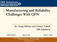
Thermal Degradation/Decomposition<br />
Massive delam<strong>in</strong>ation of conventional high-Tg FR-4 4-layer PCB after<br />
lead-free assembly with 260°C peak reflow temperature;<br />
shown <strong>in</strong> 2 views: left to emphasize the delam<strong>in</strong>ation, right to show<br />
the structure details.<br />
Source: Cookson Electronics/Polyclad, USA<br />
23
Proposed<br />
Solder<strong>in</strong>g Temperature Impact Index<br />
The problem with the current IPC slash sheets is that they are to<br />
complex to be of practical use <strong>for</strong> the PCB designers. The STII is<br />
designed to give the designer an immediate feed-back whether<br />
or not to further consider this slash sheet product<br />
Tg + Td<br />
STII = [% thermal expansion 50 to 260°C]10<br />
2<br />
Examples: Tg =140°C, Td(5%) = 320°C, 4.3% TE 50260°C<br />
STII = 187<br />
Tg =175°C, Td(5%) = 350°C, 4.0% TE 50260°C<br />
STII = 223<br />
Possible range of STII ~150 to 250; specify STII 215<br />
(<strong>for</strong> th<strong>in</strong> PCBs STII 205 is likely sufficient).<br />
24
IPC-4101<br />
IPC-4101 (December 1997)<br />
—30 Slash Sheets<br />
IPC-4101A (December 2001)—Amendment 1 (June 2002)<br />
IPC-4101B (March 2006)<br />
—55 Slash Sheets<br />
<strong>in</strong>cludes six (6) “specification sheets describ<strong>in</strong>g FR-4 base<br />
materials compatible with lead-free assembly”:<br />
—IPC-4101 B/ 99: High Tg FR-4, <strong>in</strong>organic fillers<br />
—IPC-4101 B/101: Low Tg FR-4, <strong>in</strong>organic fillers<br />
—IPC-4101 B/121: Low Tg FR-4, no fillers<br />
—IPC-4101 B/124: High Tg FR-4, no fillers<br />
—IPC-4101 B/126: Very High Tg FR-4, <strong>in</strong>organic fillers<br />
—IPC-4101 B/129: Very High Tg FR-4, no fillers<br />
25
IPC-4101/A/B<br />
STATED INTENTION:<br />
The stated <strong>in</strong>tention <strong>for</strong> IPC-4101B “is to provide the<br />
typical composition, application, per<strong>for</strong>mance<br />
characteristics and market <strong>for</strong> each base material.”<br />
Specific Keyword searches, e.g. “<strong>Lead</strong>-<strong>Free</strong> FR-4,” lead to<br />
appropriate slash sheets.<br />
These ‘Keywords’ are not requirements, “they are simply<br />
<strong>in</strong><strong>for</strong>mation” and are <strong>in</strong>tended “For Search Only.”<br />
PROBLEM:<br />
The ‘Keywords,’ while “For Search Only,” do imply<br />
certa<strong>in</strong> per<strong>for</strong>mance capabilities.<br />
Lets look at an example <br />
26
IPC-4101/A/B<br />
For the six (6) “<strong>Lead</strong>-<strong>Free</strong> Compatible” slash sheets :<br />
Slash<br />
Keyword<br />
Tg<br />
Td<br />
TE(50260<br />
260°C)<br />
Sheet LF<br />
Hi Td<br />
Lo zCTE<br />
[°C]<br />
[°C]<br />
[%]<br />
/ 99<br />
/101<br />
/121<br />
/124<br />
/126<br />
/129<br />
LF<br />
Limited<br />
<br />
NO<br />
<br />
NO<br />
<br />
Limited<br />
<br />
<br />
<br />
<br />
NO<br />
<br />
NO<br />
<br />
<br />
<br />
<br />
Limited<br />
<br />
NO<br />
<br />
NO<br />
<br />
Limited<br />
<br />
<br />
<br />
<br />
150<br />
110<br />
110<br />
150<br />
170<br />
170<br />
160<br />
325<br />
310<br />
310<br />
325<br />
340<br />
340<br />
335<br />
3.5<br />
4.0<br />
4.0<br />
3.5<br />
3.0<br />
3.0<br />
3.2<br />
STII<br />
202<br />
170<br />
170<br />
202<br />
225<br />
225<br />
215<br />
The current slash sheets need to either have the requirements<br />
tightened up or the ‘Keywords’ changed to reflect their capabilities.<br />
27
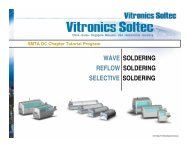
Impact of Copper Plat<strong>in</strong>g<br />
Thickness on PTH/PTV <strong>Reliability</strong><br />
Thicker copper plat<strong>in</strong>g <strong>in</strong> PTH/PTV barrels clearly result <strong>in</strong> more<br />
reliable PTH/PTV <strong>in</strong>terconnect structures.<br />
Note: The copper<br />
plat<strong>in</strong>g thickness<br />
requirement <strong>in</strong><br />
PTH/PTV barrels has<br />
been reduced from<br />
1.0 mils to 0.8 mils to<br />
accommodate slower<br />
plat<strong>in</strong>g speeds <strong>in</strong><br />
high-aspect ratio<br />
PTH/PTVs.<br />
Fluidized Sand -T-Shock 25°C260°C,<br />
hole : 13.5 mils<br />
Source: IPC-TR-579<br />
28
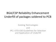
Impact of Hole Diameter and PCB<br />
Thickness on PTH/PTV <strong>Reliability</strong><br />
The reliability of PTH/PTV <strong>in</strong>terconnect structures decreases with<br />
decreas<strong>in</strong>g drilled hole diameter and <strong>in</strong>creas<strong>in</strong>g PWB thickness.<br />
Note: The test<strong>in</strong>g <strong>for</strong><br />
the round rob<strong>in</strong><br />
program reported on<br />
<strong>in</strong> IPC-TR-579 was<br />
arbitrarily, and<br />
un<strong>for</strong>tunately,<br />
term<strong>in</strong>ated after 400<br />
cycles.<br />
<br />
<br />
<br />
T-Cycle;<br />
-65°C+125°C<br />
mils<br />
<br />
PCB THICKNESS<br />
Source: IPC-TR-579<br />
29
Number of Cycles<br />
1000<br />
900<br />
800<br />
700<br />
600<br />
500<br />
400<br />
300<br />
200<br />
Impact of Hole Diameter on<br />
PTH/PTV <strong>Reliability</strong><br />
FR-4 PCB, h=90 mils, T g =175°C<br />
HATS: -40145<br />
145°C, 0.25 m<strong>in</strong>. dwells<br />
ATC: -40145<br />
145°C, 10 m<strong>in</strong>. dwells<br />
Source: Tim Estes, Conductor Analysis, Vicka White, Honeywell, USA<br />
100<br />
0<br />
10 12 13.5 16<br />
10<br />
12 13.5 16<br />
Drilled Hole Diameter [mils]<br />
30
<strong>Reliability</strong> Assurance Test<br />
Comparison: ATC, HATS & IST Results<br />
100<br />
Courtesy of Rick Snyder, Delphi Inc., USA<br />
Failures,<br />
[%]<br />
80<br />
60<br />
40<br />
Fab A<br />
Fab B<br />
20<br />
Fab C<br />
to<br />
1250<br />
0<br />
0 100 200 300 400 500 600 700 800 900 1000<br />
Cycles<br />
Fabs: FR-4, T g =170°C, 31 mil-thick PCB, 8 & 10 mil-diameter holes<br />
TS: -40°C+145°C/60 m<strong>in</strong>ute cycle<br />
HATS: -40°C+145°C/14 m<strong>in</strong>ute cycle<br />
IST: RT+170°C/10 m<strong>in</strong>ute cycle<br />
31
Loss of Life<br />
Due to Solder<strong>in</strong>g Processes (1)<br />
% Failed<br />
90<br />
75<br />
50<br />
25<br />
10<br />
5<br />
2<br />
1<br />
10 2<br />
<br />
<br />
<br />
<br />
<br />
<br />
<br />
<br />
30%<br />
<br />
<br />
<br />
<br />
200 500 10 3 2,000 5,000<br />
<br />
Cycles-to-Failure<br />
FR-4 PCB-PTVs,<br />
=13.5 mils [0.34 mm],<br />
h =100 mils [2.54 mm],<br />
Grid: 50 mils [1.3 mm]<br />
10 layers, non-functional pads,<br />
ATC: -55125<br />
125°C<br />
Assembly simulation:<br />
5 x reflow @ 215°C,<br />
= 4.1<br />
No assembly simulation,<br />
= 3.7<br />
10 4<br />
32
% Failed<br />
90<br />
75<br />
50<br />
25<br />
10<br />
5<br />
2<br />
1<br />
10 2<br />
<br />
33%<br />
50% <br />
<br />
<br />
<br />
<br />
Loss of Life<br />
Due to Solder<strong>in</strong>g Processes (2)<br />
<br />
<br />
<br />
<br />
200 500 10 3 2,000 5,000<br />
Cycles-to-Failure<br />
Courtesy of Paul Reid, PWB Solutions, Canada<br />
FR-4 PCB-PTVs,<br />
=13.5 mils [0.34 mm],<br />
h =102 mils [2.60 mm],<br />
Grid: 50 mils [1.3 mm]<br />
10 layers, non-functional pads,<br />
ATC: +25150<br />
150°C<br />
Assembly simulation:<br />
3 x reflow @ 230°C,<br />
= 2.3<br />
No assembly simulation,<br />
= 5.1<br />
10 4<br />
33
Engelmaier Fatigue Life Prediction<br />
N f<br />
–0.6 D 0.75 f<br />
+ 0.9 S u<br />
E<br />
<br />
exp D <br />
f<br />
<br />
0.36<br />
( )<br />
Plastic Stra<strong>in</strong><br />
Elastic Stra<strong>in</strong><br />
Low-Cycle<br />
High-Cycle<br />
Fatigue<br />
Fatigue<br />
Nf =mean cyclestofailure<br />
D f =fatigue ductilityfrom IPCTM2.4.2.1<br />
Effective Cyclic<br />
Stra<strong>in</strong><br />
Range<br />
S u =ultimate tensilestrength<br />
E =modulusof elasticity<br />
This equation is based on empirical relationships between fatigue behavior<br />
and tensile properties; it needs to be solved by iteration.<br />
It is the basis <strong>for</strong> IPC-TM-2.4.2.1, ‘Flexural Fatigue and Ductility, Foil’ and ASTM-<br />
E796 ‘Standard Method <strong>for</strong> Ductility Test<strong>in</strong>g of Metallic Foil’<br />
<br />
<br />
<br />
0.1785 log 105<br />
N f = max eff<br />
( )<br />
34
Plated-Through Via<br />
Barrel Crack<br />
Barrel cracks occur near center of<br />
PWB— highest load— at prepreg layer<br />
— higher res<strong>in</strong> content.<br />
Res<strong>in</strong> recession gives a clear<br />
<strong>in</strong>dication of the <strong>for</strong>ces at work caus<strong>in</strong>g<br />
the plastic de<strong>for</strong>mation of the copper<br />
barrel.<br />
35
Inner-Layer (Post) Separation<br />
Inner-layer adhesive failure<br />
occurs on heat<strong>in</strong>g when res<strong>in</strong><br />
expands compress<strong>in</strong>g barrel<br />
and <strong>in</strong>ner-layers cannot move<br />
enough; on cool<strong>in</strong>g the<br />
reced<strong>in</strong>g res<strong>in</strong> produces the<br />
separation seen.<br />
36
F<strong>in</strong>ite Element Model: Stress Results<br />
These are the stress results <strong>for</strong> the copper barrel and <strong>in</strong>nerlayers of the<br />
pr<strong>in</strong>ted wir<strong>in</strong>g board.<br />
Note: The largest<br />
stresses occur at<br />
the ‘shoulder’ of the<br />
PTV barrel and the<br />
surface pad and at<br />
the center of the<br />
barrel.<br />
z<br />
y<br />
x<br />
Courtesy: Sh<strong>in</strong>e Rom<strong>in</strong>ger, U.S.Navy-Crane, IN, USA<br />
37
High Cu Dissolution <strong>in</strong> SAC Waves<br />
• What we know about Sn·Ag·Cu (SAC) and Sn·Ag·Cu·Xy<br />
solders:<br />
Dissolve Cu and other base metals faster (about 2x) than Sn/Pb<br />
can be a real problem at the mouth of plated-through holes<br />
and vias<br />
Double wave-s<strong>in</strong>gle pass<br />
35 μm [1.4 mils]<br />
28 μm [1.1 mils]<br />
Reflow<br />
35 μm [1.4 mils]<br />
22 μm [0.9 mils]<br />
Source: Biglari, et al, IDEALS, Europe<br />
Source: Th. Ahrens, Fraunhofer Institut, Germany<br />
38
Vapor Pressure<br />
Load Drivers<br />
Another important load driver is absorbed<br />
moisture with<strong>in</strong> the PCB<br />
• PCB res<strong>in</strong>s absorb moisture; this moisture can be<br />
removed prior to solder<strong>in</strong>g processes by a moisture<br />
removal bak<strong>in</strong>g step.<br />
• The higher solder<strong>in</strong>g temperatures <strong>for</strong> LF-solders<br />
require more thorough moisture removal—the vapor<br />
pressure roughly doubles from 220°C to 260°C.<br />
Any rema<strong>in</strong><strong>in</strong>g moisture will vaporize and create high<br />
vapor pressure levels with<strong>in</strong> the PCB.<br />
These vapor pressures can rupture the PCB matrix and<br />
separate PCB layers.<br />
39
Water Vapor Pressure Induced<br />
PCB Layer<br />
Separation<br />
Note: Top photo is<br />
from SMT reflow<br />
process; bottom<br />
picture is from rework<br />
procedure.<br />
Courtesy of D. Mattix, Qualcomm Inc., USA<br />
40
Micro-Via Resistance Change<br />
After Assembly Simulation<br />
Change <strong>in</strong> resistance of 86<br />
daisy-cha<strong>in</strong> nets consist<strong>in</strong>g<br />
of 146 μ-vias each after 6<br />
reflow oven passes with<br />
215°C C peak reflow<br />
temperature.<br />
Change <strong>in</strong> Via Net Resistance [%]<br />
20.0<br />
18.0<br />
16.0<br />
14.0<br />
12.0<br />
10.0<br />
8.0<br />
6.0<br />
4.0<br />
2.0<br />
0.0<br />
12 Po<strong>in</strong>ts<br />
Courtesy of Ron Rhodes, Conductor Analysis Technologies, Inc., USA<br />
- 2.0<br />
5 7 9 11<br />
Hole Diameter [mils]<br />
41
Micro-Via Resistance Change<br />
After T-Cycl<strong>in</strong>g<br />
Change <strong>in</strong> resistance of<br />
110 daisy-cha<strong>in</strong> nets<br />
consist<strong>in</strong>g of 146 μ-vias<br />
each after 500 cycles of<br />
-55+95°C.<br />
Note: : 6 reflow cycles are<br />
significantly more<br />
damag<strong>in</strong>g than 500<br />
cycles with T=150°C<br />
Change <strong>in</strong> Via Net Resistance [%]<br />
20.0<br />
18.0<br />
16.0<br />
14.0<br />
12.0<br />
10.0<br />
8.0<br />
6.0<br />
4.0<br />
2.0<br />
0.0<br />
- 2.0<br />
4 Po<strong>in</strong>ts<br />
5 7 9 11<br />
Hole Diameter [mils]<br />
Courtesy of Ron Rhodes, Conductor Analysis Technologies, Inc., USA<br />
42
SOLID<br />
TECHNICAL<br />
UNDERSTANDING<br />
43
Thank You!<br />
Are there any questions?<br />
44
Workshops by Werner Engelmaier:<br />
•Interconnect Failures and Design <strong>for</strong> <strong>Reliability</strong> <strong>for</strong> Plated-<br />
Through Holes/Vias<br />
•How to Specify PCBs to Reliably Survive the RoHS-Mandated<br />
<strong>Lead</strong>-<strong>Free</strong> Solder<strong>in</strong>g Processes<br />
•Solder Jo<strong>in</strong>t <strong>Reliability</strong>—<br />
•Part 1: Fundamentals <strong>in</strong> Solder Jo<strong>in</strong>t <strong>Reliability</strong><br />
•Part 2: Failure Mode and Root Cause Analyses (Fatigue,<br />
Brittle Fracture, ENIG)<br />
•Part 3: Acceleration Models, Accelerated <strong>Reliability</strong> Tests<br />
and Screen<strong>in</strong>g Procedures<br />
•Part 4: <strong>Reliability</strong> <strong>Issues</strong> <strong>for</strong> <strong>Lead</strong>-<strong>Free</strong> Solder<strong>in</strong>g<br />
•<strong>Reliability</strong> Concerns <strong>in</strong> Electronic Packag<strong>in</strong>g<br />
45