TESCERA ATL - Bisco, Inc.
TESCERA ATL - Bisco, Inc.
TESCERA ATL - Bisco, Inc.
Create successful ePaper yourself
Turn your PDF publications into a flip-book with our unique Google optimized e-Paper software.
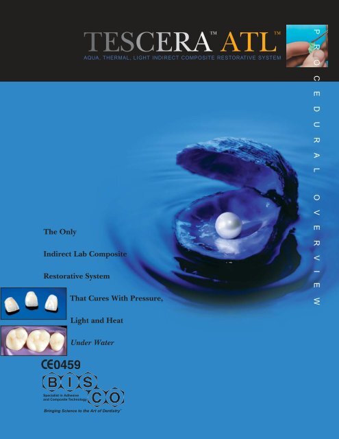
<strong>TESCERA</strong> <strong>ATL</strong><br />
AQUA, THERMAL, LIGHT INDIRECT COMPOSITE RESTORATIVE SYSTEM<br />
The Only<br />
Indirect Lab Composite<br />
Restorative System<br />
That Cures With Pressure,<br />
TM<br />
TM<br />
P R O C E D U R A L O V E R V I E W<br />
Light and Heat<br />
Under Water<br />
Specialist in Adhesive<br />
and Composite Technology<br />
Bringing Science to the Art of Dentistry
OPERATING MANUAL<br />
Table of Contents<br />
Page<br />
1. Introduction 1<br />
A. System Contents 1<br />
B. <strong>TESCERA</strong> TM Product Description 1<br />
C. Set-up 2<br />
2. Safety Precautions 3<br />
3. <strong>TESCERA</strong> Operating Instructions 4<br />
A. Using the Pressure/Light Cure Cup 4<br />
B. Using the Pressure/Light/Heat Cure Cup 4<br />
C. Operator Initiated Cancel 6<br />
D. Operator Reset 6<br />
E. Indicator Matrix 6<br />
F. Two-Digit Display 6<br />
4. Advanced User Operation 7<br />
A. Sleep (Energy Saver) Mode 7<br />
B. Light Cycle Extension 7<br />
5. Fabrication Instructions 8<br />
A. <strong>TESCERA</strong> TM <strong>ATL</strong> TM Application Instructions 8<br />
B. Alternative Technique 9<br />
C. <strong>TESCERA</strong> TM Polishing Paste 9<br />
D. <strong>TESCERA</strong> TM Glazing Resin 9<br />
E. <strong>TESCERA</strong> TM Separator 9<br />
F. Add-Ons/Repairs 9<br />
G. Manual Cutbacks 9<br />
H. Preparation Guidelines—<strong>TESCERA</strong> TM Restorations 10<br />
I. Cementation of <strong>TESCERA</strong> TM Restorations 10<br />
6. Troubleshooting 11<br />
A. Hardware Indicators 11<br />
B. Error Codes—Explanations and Actions 11<br />
C. Loss of Power During a Light Cycle 13<br />
D. Loss of Power During a Heat Cycle 13<br />
E. Manual Release of Cup 13<br />
F. Cleaning 13<br />
G. Manual Cycle Cancel by Operator 13<br />
7. Maintenance and Repair 14<br />
A. Lamp Replacement 14<br />
B. Fuse Replacement 14<br />
C. Circuit Breaker Reset 14<br />
D. Adjusting Input Air Pressure 15<br />
8. System Components 15<br />
9. Warranty & Storage 16<br />
10. Specifications 16
1. Introduction INTRODUCTION<br />
You have purchased the most advanced Composite<br />
Processing System on the market. Years of research<br />
have been used to develop the science that has been<br />
incorporated into this system.<br />
A. System Contents<br />
1.1<br />
The <strong>TESCERA</strong> TM * <strong>ATL</strong> TM * System<br />
consists of:<br />
<strong>TESCERA</strong> <strong>ATL</strong> Processing Base Unit<br />
(Figure 1.1)<br />
B. <strong>TESCERA</strong> Product Description<br />
The <strong>TESCERA</strong> <strong>ATL</strong> System is a composite processing<br />
system designed to work with <strong>Bisco</strong>’s state-of-the-art<br />
<strong>TESCERA</strong> composites for indirect restorations. The<br />
<strong>TESCERA</strong> <strong>ATL</strong> System** uses a unique combination of<br />
pressure, light and heat to cure specially formulated<br />
composite materials. The <strong>TESCERA</strong> <strong>ATL</strong> System consists<br />
of a "smart" base station and two cups. The light cup is used<br />
for pressure and light curing of incremental build-ups of<br />
larger restorations. The heat cup provides pressure, light<br />
and heat, and is used for final curing of incremental<br />
build-ups and for single step mass curing. The "smart" base<br />
station recognizes either cup and performs the appropriate<br />
cycle. It is the responsibility of the user to select the proper cup for<br />
the desired step.<br />
1.2<br />
1.3<br />
1.4<br />
1.5<br />
1.6<br />
1.7<br />
<strong>TESCERA</strong> <strong>ATL</strong> Processing Cups<br />
(left: light cup, right: heat cup)<br />
(Figure 1.2)<br />
<strong>TESCERA</strong> <strong>ATL</strong> Light Cup Reflection<br />
Beads (Figure 1.3)<br />
Set of 3 Stacking Cup Inserts for<br />
Light Cup (Figure 1.4)<br />
<strong>TESCERA</strong> <strong>ATL</strong> Oxygen Scavenger<br />
Capsules (Figure 1.5)<br />
<strong>TESCERA</strong> <strong>ATL</strong> Heat Cup Basket<br />
(Figure 1.6)<br />
<strong>TESCERA</strong> <strong>ATL</strong> Composites<br />
(Figure 1.7)<br />
Pressure and light (light cup): The pressure and light cycle<br />
intentionally leaves an oxygen inhibition layer for improved<br />
adhesion between successive layers. The first part of the<br />
pressure and light cycle subjects the restoration to pressure<br />
only, which reduces defects and porosity in the composite<br />
while it is still compliant. The second part of the pressure<br />
and light cycle maintains the pressure and light-cures to<br />
harden the composite.<br />
Pressure, light and heat, under water (heat cup): This cup<br />
adds a heat cycle in addition to the already described pressure<br />
and light sequence. The restoration is immersed in<br />
water (which does not have any adverse effect on the<br />
uncured composite). Heat is transferred quickly to the<br />
composite via water, which, with the help of a special<br />
additive, eliminates the oxygen inhibited layer, allowing a<br />
completely cured, very hard polymerized surface. Heat is<br />
transferred completely through the material providing a<br />
complete depth of cure regardless of the shade, thickness<br />
or shape of the restoration, or how the restoration is<br />
mounted and supported. Because of the heat transfer, this<br />
cup can be used for curing of a single mass of<br />
composite without concern for uncured material that is not<br />
exposed to light.<br />
WARNING: IGNORING RECOMMENDED<br />
ACTION COULD RESULT IN PERSONAL<br />
INJURY.<br />
CAUTION: IGNORING RECOMMENDED<br />
ACTION COULD RESULT IN EQUIPMENT<br />
DAMAGE.<br />
1.8<br />
Voltage Conversion Transformer<br />
(for countries with AC power source<br />
other than 120 V AC)<br />
(Figure 1.8)<br />
* <strong>TESCERA</strong> and <strong>ATL</strong> are trademarks of <strong>Bisco</strong>, <strong>Inc</strong>.<br />
** U.S. Patent: 6,386,865<br />
1
C. Set-up<br />
Introduction<br />
1.9<br />
1.10<br />
1.11<br />
1.12<br />
1.13<br />
1. Place unit on a level,<br />
sturdy surface, capable of<br />
supporting 50 lbs (23 kgs).<br />
2. Make sure power switch<br />
is in off position (down).<br />
(Figure 1.9)<br />
3. Connect AC power cord<br />
to power entry connector<br />
at base of unit.<br />
(Figure 1.10)<br />
4. Plug unit into dedicated<br />
15-amp circuit (120 V AC)<br />
with proper grounding.<br />
5. A.) Connect air inlet line<br />
to provide air supply with<br />
85-100 psi (5.8-6.8 atm).<br />
B.) Air input connector is<br />
¼" OD rigid plastic hose.<br />
C.) Push hose all the way<br />
into the adapter until the<br />
hose locks into place. The<br />
adapter rotates allowing for<br />
convenient positioning.<br />
(Figure 1.11) D.) Turn on<br />
air supply and check for<br />
leaks.<br />
6. Turn on unit (power<br />
switch up). (Figure 1.12)<br />
7. The display will read 88<br />
while the unit goes<br />
through a 20-second<br />
power-on self test (POST).<br />
(Figure 1.13) The display<br />
will then turn off, followed<br />
by 2 short beeps. The unit<br />
will display an error code if<br />
a fault is detected during<br />
self-test. (see Error Codes<br />
Section)<br />
Read the upper bar<br />
display at the rear of unit.<br />
(Figure 1.15) There are<br />
7 segments: the one at the<br />
top is red, the one at the<br />
bottom is yellow, and the<br />
ones in the middle are<br />
1.15<br />
green. Set the regulator<br />
so the lit bar is in the<br />
middle of the green<br />
segments. This will give the best range for any possible<br />
pressure changes. The regulator adjustment knob has<br />
three tracks. In the farthest down position, it is locked.<br />
In the middle position, it can be adjusted. In the farthest<br />
up position, it will turn, but will not engage the regulator<br />
adjustment control. To set the regulator, find the middle<br />
position and adjust while viewing the bars. Note: The air<br />
and power must be on. Once set, push the knob down to<br />
lock.<br />
WARNING: THE UNIT SHOULD ONLY BE USED<br />
WITH A PROPERLY GROUNDED AC SOURCE.<br />
WARNING: THE UNIT WEIGHS ABOUT 30 LBS<br />
(13kg); BE CAREFUL WHEN LIFTING.<br />
CAUTION: ONLY LIFT PROCESSING BASE BY<br />
PLACING HANDS ON HAND-RECESS IN THE<br />
BASE ON BOTH SIDES. DO NOT LIFT THE<br />
UNIT USING THE REGULATOR OR FAN.<br />
WARNING: MAKE SURE THE AIR SUPPLY<br />
PRESSURE IS TURNED OFF WHEN REMOVING<br />
THE SUPPLY HOSE.<br />
WARNING: DO NOT INSERT HANDS OR TOOLS<br />
INTO AREA WHERE CUPS ARE INTENDED TO<br />
GO. ELECTRIC SHOCK COULD RESULT.<br />
CAUTION: DO NOT INSERT HANDS OR TOOLS<br />
INTO AREA WHERE CUPS ARE INTENDED TO<br />
GO. EQUIPMENT DAMAGE COULD RESULT.<br />
WARNING: THE UNIT SHOULD NOT BE LEFT<br />
UNATTENDED WITH A HEAT CUP IN THE BASE.<br />
9. To remove the air supply hose, make sure the unit is<br />
OFF then push the outer ring of the fitting inward to<br />
release the hose, then pull the hose out.<br />
8. The input air regulator<br />
on the base of the unit is<br />
factory set for 80 psi<br />
(5.4 atm). Adjust the air<br />
pressure regulator to 80 psi<br />
(5.4 atm) if necessary.<br />
(Figure 1.14)<br />
1.14<br />
2
2. Safety SAFETY Precautions<br />
Warning: Ignoring recommended action could result in<br />
personal injury.<br />
Caution: Ignoring recommended action could result in<br />
equipment damage.<br />
Warning: The unit should only be used with a properly<br />
grounded AC source.<br />
Warning: The unit weighs about 30 lbs (13kg); be careful<br />
when lifting.<br />
Caution: Only lift processing base by placing hands on handrecess<br />
in the base on both sides. Do not lift the unit using the<br />
regulator or fan.<br />
Warning: Make sure the air supply pressure is turned off<br />
when removing the supply hose.<br />
Warning: Do not insert hands or tools into area where<br />
cups are intended to go. Electric shock could result.<br />
Caution: Do not insert hands or tools into area where cups<br />
are intended to go. Equipment damage could result.<br />
Warning: The unit should not be left unattended with a<br />
heat cup in the base.<br />
Caution: Do not use the stacking cup inserts without the<br />
light beads or the intense light beam may melt the bottom<br />
of the stacking cup.<br />
Warning: After the heat cycle, the cup will be hot, as it contains<br />
water just below boiling.<br />
Warning: Do not try to speed cooling process in any manner.<br />
Let restoration cool at room temperature. Trying to<br />
reduce cooling time (ie. blowing air) may result in fracture<br />
or reduce life span of restoration.<br />
Caution: Do not force the cup out of the base; it will come<br />
out easily once the pressure is relieved.<br />
Warning: Unit must be turned off at the AC power switch<br />
and unplugged before any servicing is performed. Setting<br />
the unit in sleep mode is not sufficient.<br />
Warning: Do not touch the bulb portion of the lamp. Oils<br />
and contamination from your fingers can cause the lamp to<br />
shatter when hot.<br />
Warning: Do not bring the lamp near your eyes. The bulb<br />
envelope of the lamp is under pressure and can<br />
shatter and explode, causing serious eye injury.<br />
Warning: Do not use latex or exam gloves as heat<br />
protection to remove a hot lamp.<br />
Caution: U.S. Federal law restricts this device to sale by or<br />
on the order of a dental professional.<br />
Warning: Do not immerse the light cup in water.<br />
Caution: Do not use water in the light cup.<br />
Warning: Do not attempt to remove the light cup from the<br />
base during a cycle.<br />
Warning: Grip the cups securely before removing<br />
(dropping may result in injury).<br />
Warning: Always use water in the heat cup.<br />
Caution: Do not use the stacking cup inserts in the heat<br />
cup.<br />
Warning: To reduce cycle times, the heat cup does not<br />
cool down to room temperature, but will be slightly below<br />
boiling. Care should be taken when removing the cup and<br />
handling it afterwards. Scalding can result.<br />
Warning: Do not attempt to remove the cup before the<br />
FINISH LED is on steady.<br />
Warning: Do not immerse the heat cup in water.<br />
Warning: If water is spilled on floor, mop floor before<br />
using unit. Do not operate unit while standing in water.<br />
Warning: Wear appropriate protection on feet.<br />
3
3. Tescera OPERATING Operating Instructions INSTR<br />
Prepare a restoration as recommended. See Section 5.<br />
A. Using the Pressure/Light Cure Cup<br />
3.1<br />
3.2<br />
3.3<br />
3.4<br />
3.5<br />
1. Place the restoration in<br />
the bed of white reflection<br />
beads in the light cup.<br />
(Figure 3.1) The bed<br />
of beads acts as a<br />
support for the work<br />
by holding the dowel<br />
pin upright as well as<br />
being a reflector and<br />
diffuser of light.<br />
The light cup handle is<br />
gray. (Figure 3.2) Use 1,<br />
2 or 3 stacking cup inserts<br />
to position the restoration<br />
close to the top of the cup,<br />
but below the rim. Transfer<br />
the light beads from insert<br />
to insert, as needed,<br />
depending on size of die,<br />
model and restoration.<br />
Offset each cup so the<br />
solid portion of its bottom<br />
rests on the legs of the one<br />
below it.<br />
2. In STANDBY mode, the<br />
RUN LED will blink slowly<br />
(once every 2-3 seconds).<br />
Insert the light cup in the<br />
base. (Figure 3.3)<br />
The unit will beep when<br />
the cup is properly inserted<br />
in position. (Figure 3.4)<br />
and the RUN LED will<br />
blink fast (once per second).<br />
The base is now in<br />
the READY MODE. The<br />
base will acknowledge the<br />
light cup and display _L.<br />
For additional options, see<br />
Advanced User Section.<br />
3. Press the START button<br />
(Figure 3.5) and the cycle<br />
will begin. The base has<br />
detected that the light cup<br />
is inserted and will<br />
automatically run the cycle<br />
of pressure and light<br />
(approximately 2 minutes).<br />
The RUN LED will be<br />
steadily lit during the rest<br />
of the cycle.<br />
4. When the cycle is complete and all the air pressure has<br />
been released, the FINISH LED will light, the RUN LED<br />
will turn off, and the unit will give a short beep.<br />
3.6<br />
3.7<br />
3.8<br />
5. When the cycle is<br />
complete, remove the cup.<br />
(Figure 3.6)<br />
CAUTION: DO NOT USE THE STACKING CUP<br />
INSERTS WITHOUT THE LIGHT BEADS OR<br />
THE INTENSE LIGHT BEAM MAY MELT THE<br />
BOTTOM OF THE STACKING CUP.<br />
WARNING: DO NOT IMMERSE THE LIGHT CUP<br />
IN WATER!<br />
CAUTION: DO NOT USE WATER IN THE<br />
LIGHT CUP!<br />
WARNING: DO NOT ATTEMPT TO REMOVE THE<br />
LIGHT CUP FROM THE BASE DURING A CYCLE!<br />
The system uses a unique<br />
inflatable seal (Figure 3.7)<br />
between the top surface of<br />
the cup (Figure 3.8) and<br />
the bottom of the upper<br />
pressure chamber.<br />
(Figure 3.7) This allows the<br />
cup to be inserted and<br />
removed with minimal<br />
resistance, yet provides a<br />
sufficient pressure seal.<br />
The cup material is treated<br />
to harden the surface, but<br />
care must be taken to keep<br />
the top surface from<br />
getting nicked, dented,<br />
scratched, etc., or the ability<br />
of the cup to seal against<br />
pressure will be affected.<br />
WARNING: GRIP THE CUPS SECURELY<br />
BEFORE REMOVING (DROPPING MAY RESULT<br />
IN INJURY).<br />
B. Using the Pressure/Light/Heat Cure Cup<br />
3.9<br />
WARNING: ALWAYS USE WATER IN THE HEAT CUP.<br />
CAUTION: DO NOT USE THE STACKING CUP<br />
INSERTS IN THE HEAT CUP.<br />
1. Place the restoration in<br />
the basket. (Figure 3.9)<br />
4
UCTIONS<br />
3.10<br />
3.10<br />
3.11<br />
Place the basket into the<br />
black heat cup. (Figure 3.10)<br />
The large hole in the<br />
basket lines up with the<br />
boss in the bottom of the<br />
heat cup, opposite the handle.<br />
2. Place just enough cool<br />
tap or distilled water in the<br />
cup to cover the top of the<br />
restoration by ½", and less<br />
than enough to cover the<br />
sides of the basket.<br />
(Figure 3.10)<br />
Drop an Oxygen Scavenger<br />
Capsule in the water before<br />
inserting the cup in the<br />
base. (Figure 3.11) Use a<br />
new capsule for every cycle.<br />
3. In STANDBY mode, the<br />
RUN LED will blink slowly<br />
(once every 2-3 per<br />
second). Insert the heat cup<br />
in the base.<br />
(Figure 3.12)<br />
base will run at low speed. Once the unit has reached the<br />
appropriate temperature and begins cooling, the fan will<br />
turn back on, indicating the unit is in the cooling stage.<br />
During the last 30 seconds of the cooling cycle the<br />
FINISH LED will blink fast (2 times per second), indicating<br />
the cycle is in the last 30 seconds. The display will count<br />
down from 30 to 0 to indicate the time left in the cooling<br />
cycle.<br />
6. If the cooling cycle is not completed in 7 minutes, there is<br />
a possible fault of the main fan or the cup thermostat is<br />
stuck open. The unit will cool an additional 20 minutes and<br />
ERROR CODE 10 will be displayed (see Troubleshooting<br />
Section). When the finish indicator comes on, along with<br />
the ERROR light, remove the cup. The operator must<br />
determine if the main fan is working. If so, press and hold<br />
START and CANCEL for 5 seconds to reset. When the cup<br />
is put back on the base, it will be tested to determine if the<br />
thermostat has failed.<br />
7. When the cycle is complete and all air pressure has been<br />
released, the FINISH LED will light steady, the RUN LED<br />
will turn off, and the unit will give a short beep.<br />
8. The cup can now be removed.<br />
WARNING: TO REDUCE CYCLE TIMES, THE<br />
HEAT CUP DOES NOT COOL DOWN TO ROOM<br />
TEMPERATURE, BUT WILL BE SLIGHTLY BELOW<br />
BOILING. CARE SHOULD BE TAKEN WHEN<br />
REMOVING THE CUP AND HANDLING IT<br />
AFTERWARDS. SCALDING CAN RESULT.<br />
3.12<br />
The unit will beep when<br />
the cup is properly<br />
inserted in position and<br />
H_ will be displayed.<br />
(Figure 3.13) The RUN<br />
LED will blink fast (2 times<br />
per second). The base is<br />
now in the READY MODE.<br />
3.13<br />
4. Press the START button<br />
and the cycle will begin.<br />
(Figure 3.14) The base will<br />
detect that the heat cup is<br />
inserted and will<br />
automatically run the full<br />
cycle of pressure, light and<br />
heat (and cool) for<br />
approximately 10-13<br />
minutes. The RUN LED<br />
3.14<br />
will be steadily lit during the<br />
rest of the cycle. The cycle<br />
time varies depending on the size of the restoration and the<br />
starting temperature of the water.<br />
5. During the heat cycle, the main fan in the bottom of the<br />
WARNING: DO NOT ATTEMPT TO REMOVE THE<br />
CUP BEFORE THE FINISH LED IS ON STEADY.<br />
9. To quickly cool the cup for the next cycle, rinse twice<br />
with cold water by filling, letting stand 1 minute, then pouring<br />
out and repeating.<br />
WARNING: DO NOT IMMERSE THE HEAT CUP<br />
IN WATER!<br />
The system uses a unique inflatable seal between the top<br />
surface of the cup and the top of the pressure chamber.<br />
This allows the cup to be inserted and removed with<br />
minimal resistance. The cup material is treated to harden<br />
the surface, but care must be taken to keep the top surface<br />
from getting nicked, dented, scratched, etc., or the ability of<br />
the cup to seal against pressure will be affected. See Figure<br />
3.7 & 3.8, page 4.<br />
WARNING: GRIP THE CUPS SECURELY<br />
BEFORE REMOVING (DROPPING MAY RESULT<br />
IN INJURY).<br />
WARNING: IF WATER IS SPILLED ON FLOOR,<br />
MOP FLOOR BEFORE USING UNIT. DO NOT<br />
OPERATE UNIT WHILE STANDING IN WATER.<br />
WARNING: WEAR APPROPRIATE PROTECTION<br />
ON FEET.<br />
5
C. Operator Initiated Cancel:<br />
D. Operator Reset:<br />
Operating Instructions<br />
The operator can<br />
CANCEL the cycle at<br />
any time; however, the<br />
portion of the cycle the<br />
unit is in will determine<br />
the unit’s response. To<br />
CANCEL, press and hold<br />
3.15 the CANCEL button for 2<br />
seconds, then release<br />
3.16<br />
(Figure 3.15). The display will read “11” and the ERROR<br />
LED will blink fast.<br />
E. Indicator Matrix<br />
After a fault or error<br />
condition is recognized<br />
and cleared or an<br />
operator initiated<br />
CANCEL is activated, the<br />
unit must be reset. To<br />
reset the unit, press and<br />
hold the START and<br />
CANCEL buttons<br />
together (Figure 3.16) for 2 seconds until the error light<br />
goes off. The display will read “88” as it proceeds through<br />
the self-test. If no fault or error conditions are found, the<br />
display will change to “0” and the unit will be in STAND-<br />
BY mode.<br />
RUN LED FINISH LED Mode User Action<br />
Slow blink Off Standby Waiting for cup<br />
Fast blink Off Ready Waiting for START switch to be pushed<br />
Steady Off Run Cycle No user action<br />
Steady Fast blink Last 30 seconds of Prepare for removal of the heat cup<br />
Cooling Cycle<br />
Off Steady Done Remove cup<br />
ERROR LED<br />
FINISH LED<br />
Steady Off Fault indicated Fix fault, remove cup<br />
from base and reset<br />
Fast Blink Off Operator initiated Remove cup from<br />
cycle CANCEL<br />
base and reset<br />
Slow blink Off Fault alert, but cycle Operator needs to determine suitability of<br />
continues, not cancelled the processed material. This occurs if the<br />
lamp output is interrupted during a cycle<br />
from filament burn out, overheating or<br />
fuse opening. This also is seen if the lamp<br />
access door is opened while the lamp is on.<br />
Operator must reset this error, and the<br />
unit will further diagnose the fault when<br />
returning to standby.<br />
Steady Steady Unit recovering from Allow unit to follow recovery sequence<br />
power interruption<br />
then reset.<br />
during heat cycle<br />
F. Two-Digit Display<br />
H_<br />
_L<br />
XX<br />
CP<br />
HC<br />
_ _<br />
oo•<br />
Indicates heat cup recognized<br />
Indicates light cup recognized<br />
Numeric display of error messages (see Troubleshooting Section)<br />
Alpha display—light cup in pot at power on<br />
Alpha display—heat cup in pot when sleep is activated<br />
Blinking—indicates unit in sleep mode<br />
Indicates unit awakened from sleep mode<br />
WARNING: DO NOT ATTEMPT TO REMOVE THE CUP UNTIL THE "FINISH" INDICATOR HAS COME ON.<br />
Both cycles include a pressurized period.<br />
WARNING: AFTER THE HEAT CYCLE, THE CUP WILL BE HOT, AS IT CONTAINS WATER JUST BELOW BOILING.<br />
If disposing of the water, do not spill or pour the water anywhere but in the sink.<br />
6
4. Advanced ADVANCED User Operation USER OPE<br />
A. Sleep (Energy Saver) Mode<br />
The SLEEP mode is<br />
intended to be used for<br />
long periods of inactivity<br />
of the unit. When the<br />
unit is in STANDBY<br />
4.1<br />
(RUN LED blinks once<br />
every 2-3 seconds, no<br />
cup in base), it can be<br />
placed in SLEEP mode. In SLEEP, the main fan and<br />
lamp fan are turned off, and the bottom segments of the<br />
display are blinking (like eyes closed).<br />
Entering SLEEP Mode<br />
To enter SLEEP mode from STANDBY, push and hold<br />
the SLEEP button for 1 second. (Figure 4.1) If the unit<br />
has just completed a cycle (heat or light), there will be a 5<br />
minute delay before the fans shut down to allow the unit<br />
to properly cool. The display will count down from 5 to<br />
0 in 1 minute intervals as the unit prepares to enter<br />
SLEEP. Once in SLEEP, a light cup can be<br />
inserted in the base to "close the opening", if desired. If a<br />
heat cup is inserted, an error message “HC” will be displayed<br />
and the ERROR LED will come on<br />
accompanied by a beep every 5 seconds. The heat cup<br />
must be removed.<br />
Exiting SLEEP Mode<br />
If a light cup is in place in the SLEEP Mode, it must be<br />
removed before re-awakening, or the ERROR LED and<br />
the message “CP” will be displayed. To exit SLEEP, press<br />
and hold the SLEEP button for 1 second. The display<br />
will change from “_ _” to “oo” (eyes shut to eyes open),<br />
and a short beep will be emitted. The unit will perform<br />
self-test then return to STANDBY and be ready to accept a<br />
cup.<br />
B. Light Cycle Extension<br />
The user may increase the lamp on time during the light<br />
cycle if desired. When doing incremental build-ups on<br />
large bridges or crowns where shadows may reduce light<br />
penetration proximally and at margins, longer light cycles<br />
are helpful.<br />
1. After inserting a light cup in the base, the RUN LED is<br />
blinking fast and _L is displayed.<br />
4.2<br />
2. Normal (default) light<br />
exposure is 1 minute. To<br />
extend, press and release<br />
the CANCEL button.<br />
(Figure 4.2) Light<br />
exposure time will extend<br />
to 3 minutes, and the display<br />
will read 3 L.<br />
3. Press start to begin, or press and release the<br />
CANCEL button again (see Figure 4.2) to extend the<br />
light exposure to 5 minutes. The display will read 5 L.<br />
4. Press start to begin, or...<br />
5. ...to return to a 1 minute light exposure, press and<br />
release CANCEL one more time. (see Figure 4.2) Display<br />
will read _L.<br />
6. If an extended light cycle is selected and run, the unit<br />
will return to the 1 minute default on the next cycle.<br />
Note: Not available in heat mode.<br />
7
5. Fabrication FABRICATION Instructions INST<br />
<strong>TESCERA</strong><strong>ATL</strong><br />
AQUA, THERMAL, LIGHT INDIRECT COMPOSITE RESTORATIVE SYSTEM<br />
TM<br />
TM<br />
FABRICATION INSTRUCTIONS<br />
Gray Light Cup<br />
(Pressure and Light)<br />
Black Heat Cup<br />
(Pressure, Heat, Light<br />
and Water)<br />
The light cup uses pressure and<br />
light. This light cup should be<br />
used for an increment cure. Place<br />
restoration(s) in light cup instead<br />
of using a hand held light or step<br />
light. Use the <strong>TESCERA</strong> reflection<br />
beads to fill stacking cups and<br />
adjust to desired height. The beads<br />
serve as a reflection bed and also<br />
support the die(s).<br />
Note: The incremental cure, which<br />
takes place in the light cup, forces<br />
porosity out of the composite with<br />
pressure and then light-cures.<br />
CAUTION: DO NOT USE<br />
WATER IN THE LIGHT CUP.<br />
The final cure: Place restoration(s)<br />
in the basket and insert into the<br />
heat cup for complete<br />
polymerization. Pour water into<br />
this cup, just covering the<br />
restoration(s). Add an oxygen<br />
scavenger capsule to the water.<br />
Place heat cup in curing unit and<br />
turn on.<br />
Note: This process heats, pressurizes,<br />
and light-cures the restoration(s).<br />
The water distributes the heat<br />
evenly and keeps an air-inhibited<br />
layer from forming.<br />
CAUTION: ALWAYS USE<br />
WATER IN THE HEAT CUP.<br />
A. <strong>TESCERA</strong> <strong>ATL</strong> Applications Instructions<br />
5.1<br />
5.2<br />
5.3<br />
5.3a<br />
Step 1. Apply a thin layer of die<br />
hardener or ultra thin<br />
cyanoacrylate glue (ie. “SUPER-<br />
GLUE ” ) over the preparation die<br />
extending over margins. (Remember<br />
to have blocked-out all undercuts.)<br />
(Figure 5.1)<br />
Step 2. Apply one thin layer of<br />
<strong>TESCERA</strong> Separator over the<br />
preparation, slightly extending over<br />
margins. Gently wipe or blow off<br />
all excess Separator. (Figure 5.2)<br />
Step 3. Apply a thin layer of<br />
<strong>TESCERA</strong> Dentin Composite<br />
to the preparation and cure the<br />
dentin layer in light cup.<br />
(Figure 5.3 & 5.3a)<br />
5.5<br />
5.6<br />
5.7<br />
5.5a<br />
Step 5. Apply <strong>TESCERA</strong> <strong>Inc</strong>isal<br />
Composite and cure incisal layer<br />
in light cup. (Figure 5.5 & 5.5a)<br />
Step 6. You should now be able to<br />
remove the restoration from the die<br />
and place it in the heat cup for the<br />
final cure. Fill this cup with water,<br />
just covering the<br />
restoration(s) and add an oxygen<br />
scavenger capsule. This process<br />
fully polymerizes and removes the<br />
oxygen-inhibited layer.<br />
(Figures 5.6 & 5.7)<br />
Note: If more incremental<br />
polymerization is needed, refer to<br />
the Advanced User Operation<br />
Section.<br />
5.4<br />
5.4a<br />
Step 4. Apply <strong>TESCERA</strong> Body<br />
Composite over the dentin<br />
layer and cure the body layer<br />
in light cup. (Figures 5.4 & 5.4a)<br />
WARNING: DO NOT TRY TO SPEED COOLING<br />
PROCESS IN ANY MANNER. LET RESTORATION<br />
COOL AT ROOM TEMPERATURE. TRYING TO<br />
REDUCE COOLING TIME (ie. BLOWING AIR) MAY<br />
RESULT IN FRACTURE OR REDUCE LIFE SPAN OF<br />
RESTORATION.<br />
8
UCTIONS<br />
5.8<br />
5.9<br />
5.10<br />
B. Alternative Technique<br />
Step 7. Remove the restoration<br />
from the curing unit, finish, and polish<br />
or glaze.<br />
(Figures 5.8, 5.9 & 5.10)<br />
Note: You may use <strong>TESCERA</strong><br />
Sculpting Resin to aid in building<br />
and manipulating the composite<br />
material. Do not mix or incorporate<br />
Sculpting Resin into the composite<br />
material, as it will cause the<br />
material to cure prematurely. With all<br />
<strong>TESCERA</strong> composite materials,<br />
avoid unnecessary exposure to<br />
ambient light, as it will cause the<br />
material to cure prematurely.<br />
You may build your restoration in<br />
any manner you wish. It is not necessary<br />
to use the light cup.<br />
You may build the restoration<br />
and go into the final<br />
5.11<br />
cure using the heat cup.<br />
If you choose to do so,<br />
you will need to pour a<br />
separate model and die as you will be unable to remove<br />
the restoration from the die. Placing the restoration and<br />
die in the heat cup (Figure 5.11) will result in the die being<br />
destroyed, similar to a refractory die. This is due to the<br />
high temperature and pressure. The light cup should<br />
only be used as an increment cure, tacking the composite<br />
into place using pressure and light, preventing porosity<br />
throughout the whole restoration. Do not use the light<br />
cup for the final cure.<br />
C. <strong>TESCERA</strong> Polishing Paste<br />
5.12<br />
• Use a bristle brush or a cotton<br />
buff wheel at a low speed<br />
impregnated with <strong>TESCERA</strong><br />
Polishing Paste.<br />
• In a slow circular motion, polish the surface of the<br />
restoration. (Figure 5.12)<br />
• Clean excess paste off of the restoration using a steam<br />
cleaner and/or ultra sonic cleaner.<br />
• Complete the polishing process by using a clean<br />
cotton buff wheel.<br />
Note: For a glazed finish, use <strong>TESCERA</strong> Glazing Resin<br />
instead of polishing.<br />
D. <strong>TESCERA</strong> Glazing Resin<br />
5.13<br />
• Thoroughly finish (pumice) the<br />
area of the restoration(s) to be glazed.<br />
• Rinse and air-dry (oil free).<br />
• Apply a thin layer of <strong>TESCERA</strong><br />
Glazing Resin evenly, brushing on<br />
smoothly in one direction.<br />
(Figure 5.13)<br />
• Light-cure for 5 minutes in a light booth or with a hand<br />
held light such as <strong>Bisco</strong>’s VIP * for 20 seconds per surface<br />
at 500 mw/cm 2 .<br />
• When curing is complete, remove residue with<br />
isopropyl alcohol, and wash with soap and water. If additional<br />
layers of Glazing Resin are desired, do not remove<br />
residue until all layers are completed.<br />
E. <strong>TESCERA</strong> Separator<br />
• Apply one thin layer of <strong>TESCERA</strong> Separator to the die.<br />
(Die should be blocked-out and sealed before you<br />
apply separator.)<br />
• Blow off any excess separator with air, or wipe off<br />
gently with tissue.<br />
Do not leave pooled or excess Separator on die.<br />
Composite will not adhere to the die if excess Separator<br />
remains.<br />
F. Add-Ons/Repairs<br />
1. Prepare the composite surface by sandblasting or<br />
roughening with a diamond burr.<br />
2. Steam clean or rinse, and air dry.<br />
3. Apply 2 coats of Composite Primer* (sold separately)<br />
to surface and air dry.<br />
4. Place a flowable composite such as ÆLITEFLO TM * or a<br />
Reinforced Microfill (microhybrid) such as <strong>TESCERA</strong> Body<br />
or <strong>Inc</strong>isal Composite in the area in need of repair.<br />
5. Contour and light-cure.<br />
6. Finish and polish.<br />
G. Manual Cutbacks<br />
Note: <strong>TESCERA</strong> Composite allows for creation of restoration to scale.<br />
1. Prepare the composite surface by sandblasting or<br />
roughening with a diamond burr.<br />
2. Steam clean or rinse, and air dry.<br />
3. Apply 2 coats of Composite Primer (sold separately) to<br />
surface, and air dry.<br />
4. Place <strong>TESCERA</strong> Composite on cut back area.<br />
5. Contour and place in the <strong>TESCERA</strong> <strong>ATL</strong> for the final<br />
cure.<br />
6. Finish and polish/glaze.<br />
* VIP and ÆLITEFLO are trademarks of <strong>Bisco</strong>, <strong>Inc</strong>.<br />
Composite Primer is manufactured by <strong>Bisco</strong>, <strong>Inc</strong>.<br />
9<br />
Fabrication Instructions
H. Preparation Guidelines<br />
I. Cementation of <strong>TESCERA</strong> Restorations Tooth Preparation<br />
Fabrication Instructions<br />
Veneer Preparation<br />
• Uniform facial reduction and depth<br />
• Facial reduction: 0.6 mm<br />
• <strong>Inc</strong>isal reduction: 1.5 mm with rounded edge line angles<br />
• Margin: butt joint<br />
Anterior Crown Preparation<br />
• <strong>Inc</strong>isal reduction: 2.0 mm with rounded edges<br />
• Facial and lingual reduction: 1.5 mm<br />
• Margin: 1.0 mm wide butt joint<br />
Posterior Crown Preparation<br />
• <strong>Inc</strong>isal reduction: 2.0 mm<br />
• Buccal and lingual reduction: 1.5 mm<br />
• Margins: 1.0 mm wide butt joint (shoulder) with<br />
rounded internal line angles<br />
Onlay Preparations<br />
• Occlusal (cuspal) reduction: approximately 2.0 mm<br />
• Tapered internal walls<br />
• Margins: butt joint (shoulder)<br />
• Round all internal line angles<br />
Note: Finish lines should not be in opposing contact areas.<br />
Inlay Preparations<br />
• Occlusal reduction: 2.0 mm<br />
• Tapered internal walls<br />
• Margins: butt joint (shoulder)<br />
• Isthmus width: 2.0 mm<br />
• Round all internal line angles<br />
Note: Finish lines should not be in opposing contact areas.<br />
Bridge Preparations<br />
• Refer to separate <strong>TESCERA</strong> Fiber Reinforcement<br />
Instructions.<br />
1. Remove provisional restoration; clean the preparation<br />
and try-in the definitive restoration. Eugenol may affect<br />
curing of some composite materials. If eugenolcontaining<br />
temporary cement was used, clean the<br />
preparation with pumice to remove all traces of the<br />
cement.<br />
2. Etch using a self-priming etchant such as TYRIAN * SPE<br />
or a phosphoric acid such as UNI-ETCH ® * or ETCH-37 *<br />
according to the manufacturer's instructions.<br />
3. Apply an adhesive, such as ALL-BOND ® * 2,<br />
ONE-STEP ® * or ONE-STEP ® PLUS according to<br />
manufacturer's instructions.<br />
Restoration Preparation:<br />
1. Sandblast internal surface of restoration for<br />
1-2 seconds. Rinse with water, and air dry.<br />
2. Apply two coats of a composite adhesion promoter, such as<br />
COMPOSITE ACTIVATOR*, to the internal surface. Dry<br />
with air syringe.<br />
3. Apply one coat of ONE-STEP or ONE-STEP PLUS. Air dry.<br />
Light-cure for 10 seconds OR apply a thin layer of a light-cured<br />
bonding resin such as D/E RESIN*. Air thin. DO NOT<br />
LIGHT-CURE.<br />
Cementation:<br />
1. Mix equal amounts of dual-cured composite cement such<br />
as ILLUSION *, CHOICE *, or DUO-LINK * base and<br />
catalyst into a uniform paste (10-15 seconds), until the paste<br />
is of a uniform color. Fill the internal<br />
surface of the restoration with the cement using an<br />
instrument or BISCO APPLICATOR*.<br />
2. Seat the restoration with gentle, passive pressure.<br />
3. Remove excess cement immediately with a brush or<br />
instrument.<br />
4. Light-cure each surface of the restoration for<br />
40 seconds.<br />
*TYRIAN, ETCH-37, ILLUSION, CHOICE, DUO-LINK and QUICK-DIE<br />
are trademarks of <strong>Bisco</strong>, <strong>Inc</strong>.<br />
UNI-ETCH, ALL-BOND and ONE-STEP are registered trademarks<br />
of <strong>Bisco</strong>, <strong>Inc</strong>.<br />
COMPOSITE ACTIVATOR and D/E RESIN are manufactured by <strong>Bisco</strong>,<br />
<strong>Inc</strong>.<br />
10<br />
BISCO APPLICATORS are distributed by <strong>Bisco</strong>, <strong>Inc</strong>.
6. Troubleshooting TROUBLESHOOTIN<br />
The <strong>TESCERA</strong> <strong>ATL</strong> has built-in self-test and diagnostic features. Refer to the following chart of indicators and error codes<br />
for an explanation of potential problems. When an error code is displayed, the cycle did not complete and reprocessing the<br />
restoration is necessary. An error code during the cycle will cancel the cycle and require a system reset (unless<br />
otherwise noted). After the problem has been resolved, the unit needs to be reset to return to STANDBY. (see Operator<br />
Reset Section) For additional technical assistance contact <strong>Bisco</strong> at 847-534-6000 or your <strong>Bisco</strong> distributor.<br />
If no display or LED’s are visible, check fuse and circuit breaker on back of unit. Note: there is a high current resettable circuit<br />
breaker and a lower amperage replaceable fuse. If either are tripped or blown, no displays will be visible.<br />
A. Hardware Indicators<br />
A set of light indicators provides some basic troubleshooting diagnostics of the power system.<br />
GREEN RED RED<br />
LED 1 LED 2 LED 1 Neon Lamp ORANGE<br />
on power board on power board on main board on power board<br />
(24V) (7V) (VCC) (Across Fuse)<br />
ON ON ON OFF NORMAL<br />
OFF ON ON OFF 24V DC fault- Contact <strong>Bisco</strong><br />
or your <strong>Bisco</strong> distributor<br />
ON OFF OFF OFF 7V DC fault- Contact <strong>Bisco</strong><br />
or your <strong>Bisco</strong> distributor<br />
ON ON OFF OFF Cable problem or main<br />
BD problem- Contact <strong>Bisco</strong><br />
or your <strong>Bisco</strong> distributor<br />
OFF OFF OFF ON Power board fuse blown-<br />
Contact <strong>Bisco</strong> or your<br />
<strong>Bisco</strong> distributor<br />
OFF OFF OFF OFF AC switch or power<br />
input fault- Contact <strong>Bisco</strong><br />
or your <strong>Bisco</strong> distributor<br />
Note: If no displays are lit, but the fans are running, the main board microprocessor is possibly faulty.<br />
B. Error Codes: Explanations and Actions<br />
Error Code Description Probable cause Remediation action<br />
1 Cup failure Cup overheated, thermal fuse opened Return cup for repair<br />
2 Line pressure too high or too low Adjust regulator using top bar of<br />
LEDs. If adjusting does not change,<br />
check input air pressure<br />
3 Heat cycle timed out Steam pressure could not be Check lip of cup and seal for foreign<br />
maintained due to leak<br />
matter or nicks, monitor lower<br />
pressure bar LEDs<br />
Heater in cup failed<br />
Contact <strong>Bisco</strong> or your <strong>Bisco</strong> distributor<br />
4 Cup pressure low Leaky seal Check lip of cup and seal for foreign<br />
matter or nicks<br />
5 POST indicator lamp burned out Replace lamp with type ENG<br />
(300 watt halogen bulb)<br />
11
Troubleshooting TROUBLESHOOTING<br />
cont.<br />
B. Error Codes Explanations and Actions cont.<br />
Error Code Description Probable cause Remediation action<br />
6 POST indicator lamp Lamp overheated, fan not working Check flow of air in lamp<br />
overtemperature sensor tripped or airflow restricted compartment. Sensor will<br />
automatically reset in 3-5 minutes<br />
8 Main fan not operational Electrical failure Contact <strong>Bisco</strong> or your <strong>Bisco</strong> distributor<br />
9 Light cup in base under pressure Power failure; light cycle interrupted Re-power and reset<br />
at power-on<br />
10 Cooling cycle timed out- more Thermostat failed or main fan Contact <strong>Bisco</strong> or your <strong>Bisco</strong> distributor<br />
than 8 minutes in cooling<br />
jammed or shorted<br />
11 Operator canceled operation Reset<br />
12 Lamp access door interlock For operator’s safety, the lamp is Close lamp access door. If problem<br />
or lamp fan not operational automatically shut off or prevented still exists, contact <strong>Bisco</strong> or your<br />
from turning on if the lamp access <strong>Bisco</strong> distributor<br />
door is opened.<br />
Note: If lamp access door is opened prior to starting a cycle (STANDBY or READY), the ERROR indicator will light and the cycle will be<br />
cancelled causing the unit to need to be reset. If the lamp access door is opened during the first 20 seconds of the lamp on portion of the<br />
cycle, an error 21 will result. If the lamp access door is open after a minimum of 20 seconds of lamp on time the ERROR LED will flash<br />
slowly, 14 will be displayed and will require reset. If the lamp access door is opened during the cooling cycle (after the lamp has been turned<br />
off), the cycle will continue but a 12 error code will be displayed and the error LED will flash slowly, indicating a caution but not an error. If<br />
the lamp access door is closed during this portion of the cycle, the unit will not require a reset.<br />
13 Cup thermostat failure Cup still hot or thermostat open Let cup cool, if still failing, contact<br />
<strong>Bisco</strong> or your <strong>Bisco</strong> distributor<br />
14 Cycle not complete, but ran a Lamp burned out during cure cycle, Check restoration for cure, see<br />
minimum of 20 seconds; cycle lamp overtemperature sensor opened errors 5 and 6<br />
continues with error LED<br />
or lamp access door opened<br />
blinking once every 2-3 seconds<br />
16 Line pressure too high Adjust regulator using top row of<br />
LEDS to lower pressure<br />
17 Heat cup in base on start-up Heat cycle interrupted due to power Unit will cool 8 minutes;<br />
under pressure loss remove cup, reset<br />
18 Base unit cannot identify Pot failure or electrical failure Contact <strong>Bisco</strong> or your <strong>Bisco</strong> distributor<br />
type of cup<br />
19 Circuit breaker or fuse open Overload or electrical failure Reset and re-power; if problem remains,<br />
contact <strong>Bisco</strong> or your <strong>Bisco</strong> distributor<br />
21 Lamp failed in first 20 seconds Lamp burned out, or overtemperature See errors 5,6,12<br />
of light-cure; not enough<br />
sensor or interlock opened<br />
curing time<br />
22 AC line input error Earth ground connection lost Contact <strong>Bisco</strong> or your <strong>Bisco</strong> distributor<br />
40 Internal communication error Contact <strong>Bisco</strong> or your <strong>Bisco</strong> distributor<br />
41 Error loading token data Retry, remove token, Contact <strong>Bisco</strong><br />
or your <strong>Bisco</strong> distributor<br />
42 Tried to load master token to Contact <strong>Bisco</strong> or your <strong>Bisco</strong> distributor<br />
memory, token was not master<br />
80 Internal communication error Contact <strong>Bisco</strong> or your <strong>Bisco</strong> distributor<br />
81 Error loading internal data Contact <strong>Bisco</strong> or your <strong>Bisco</strong> distributor<br />
CP Light cup in base at power on Cup placed in unit for storage Remove cup and reset<br />
HC Heat cup in base when activating Sleep mode not valid with heat Remove heat cup and replace<br />
sleep mode cup in base with light cup; reactivate sleep<br />
-or-<br />
-or-<br />
Heat cup in base with no<br />
Remove heat cup and reset<br />
pressure on power up<br />
12
C. Loss of Power During a Light Cycle<br />
The unit will automatically perform a depressurizing<br />
sequence and the display will read 9. Remove the cup<br />
and reset.<br />
D. Loss of Power During a Heat Cycle<br />
If power is lost during a heat cycle or the unit<br />
malfunctions, the sealing pressure is maintained between<br />
the cup and base. When this occurs, the cup may remain<br />
locked in the base. (If power is lost during the heat cycle<br />
and the pressure is released, a boil over can occur.)<br />
When the power returns, the ERROR LED will be on, and<br />
the unit will display an Error Code 17 to indicate the heat<br />
cup is in the base. The unit will first check if the heat cup<br />
is under pressure and above the safe removal temperature.<br />
If so, it will cool and the ERROR LED light will be on<br />
steady (Figure 6.1). This could take 8 minutes if the main<br />
fan is operating properly or up to 1 hour if there is a<br />
failure in the main fan. If not, the fan will run until the<br />
cup cools, and the error light will be on steady. When cool,<br />
the unit will beep and the FINISH LED will steadily light.<br />
The ERROR LED will<br />
also remain on until the<br />
unit is reset. Remove the<br />
heat cup and press and<br />
hold the CANCEL button<br />
and the START button<br />
together for<br />
2 seconds to reset. The<br />
6.1<br />
display will read "88"<br />
(normal start-up<br />
sequence), then go to STANDBY if no errors are present.<br />
If any other code is displayed, an error was found during<br />
the start-up sequence.<br />
E. Manual Release of Cup<br />
If the power in the unit<br />
or a valve in the unit fails,<br />
the cup may be removed<br />
by manually releasing the<br />
pressure in the seal. If<br />
using the heat cup and<br />
the main fan is not<br />
running, wait one hour<br />
6.2<br />
for the unit to cool to a<br />
safe temperature. Insert<br />
a rigid object into the<br />
small upper hole on the<br />
left upper back, below<br />
the left set of<br />
louvers, and locate the<br />
recessed black button.<br />
(Figure 6.2) Press and<br />
hold the button for<br />
10 seconds (Figure 6.3),<br />
6.3<br />
which releases the<br />
pressure in the seal, and<br />
allows pressure in the cup<br />
chamber to be released. It may take up to 30 seconds to<br />
completely release all the pressure in the cup chamber.<br />
CAUTION: DO NOT FORCE THE CUP OUT OF<br />
THE BASE; IT WILL COME OUT EASILY ONCE<br />
THE PRESSURE IS RELIEVED.<br />
F. Cleaning<br />
To clean the <strong>TESCERA</strong> <strong>ATL</strong>, gently wipe down with a<br />
clean soft cloth dampened with dilute mild detergent.<br />
Do not spray with aerosol or use abrasive cleaning<br />
compounds.<br />
G. Manual Cycle Cancel by Operator<br />
Anytime during a light cycle, CANCEL will advance the<br />
unit to the end of an unfinished cycle. During a heat<br />
cycle, CANCEL is not active during the cooling phase.<br />
If CANCEL is pressed during the heating phase, but<br />
before the cup reaches peak temperature, an automatic<br />
8 minutes of cooling is implemented before the cup can<br />
be removed. CANCEL is not active during a fault<br />
condition or during POST. CANCEL is not active in<br />
STANDBY or READY mode as the cycle has not been<br />
started.<br />
Troubleshooting<br />
13
7. Maintenance MAINTENANCE<br />
& Repair<br />
WARNING: UNIT MUST BE TURNED OFF<br />
AT THE AC POWER SWITCH AND<br />
UNPLUGGED BEFORE ANY SERVICING IS<br />
PERFORMED. SETTING THE UNIT IN SLEEP<br />
MODE IS NOT SUFFICIENT.<br />
A. Lamp Replacement<br />
7.1<br />
7.2<br />
7.3<br />
7.4<br />
1. To replace a lamp<br />
(error code 5), turn off<br />
power to the unit.<br />
2. Remove the lamp slide<br />
housing at the top rear of<br />
the base unit. Turn the<br />
Phillips head screw ¼<br />
turn counter clockwise to<br />
release the latch.<br />
(Figure 7.1)<br />
Carefully slide the lamp<br />
housing out of the base<br />
until it is stopped by the<br />
two tabs. (Figure 7.2)<br />
3. CAUTION: The lamp<br />
may be hot if it had been<br />
running prior to burning<br />
out. Allow sufficient time<br />
for the lamp to cool<br />
before handling it.<br />
To remove the lamp, lift<br />
the lamp out of the<br />
socket by raising the lever<br />
on the right side of the<br />
lamp holder.<br />
(Figure 7.3) The lever<br />
will lift the lamp up.<br />
4. Push the lever back<br />
down. Remove the old<br />
lamp and discard.<br />
5. Handle the new lamp by its reflector. Replace the<br />
new 300-watt halogen lamp (Type ENG) by sliding the<br />
reflector between the front plate and the support wires,<br />
while aligning the electrical contacts with the socket.<br />
(Figure 7.4) Push the lamp all the way down in the<br />
socket. If it does not go down, check to make sure the<br />
lifting lever was returned to its down position.<br />
WARNING: DO NOT TOUCH THE BULB POR-<br />
TION OF THE LAMP. OILS AND CONTAMINA-<br />
TION FROM YOUR FINGERS CAN CAUSE THE<br />
LAMP TO SHATTER WHEN HOT.<br />
WARNING: DO NOT BRING THE LAMP NEAR<br />
YOUR EYES. THE BULB ENVELOPE OF THE<br />
LAMP IS UNDER PRESSURE AND CAN SHATTER<br />
AND EXPLODE, CAUSING SERIOUS EYE INJURY.<br />
7.5<br />
WARNING: DO NOT USE LATEX OR EXAM<br />
GLOVES AS HEAT PROTECTION TO REMOVE<br />
A HOT LAMP.<br />
B. Fuse Replacement<br />
6. Slide the lamp mount<br />
back into the base,<br />
taking care that the wires<br />
go smoothly back into the<br />
base.<br />
7. Align the fastener with<br />
the latch and turn the<br />
screw ¼ turn clockwise<br />
(Figure 7.5) to close.<br />
1. To replace the fuse, turn off power to the unit.<br />
7.6<br />
2. Locate the fuse holder<br />
on the right lower back of<br />
the base unit.<br />
(Figure 7.6)<br />
3. Remove the fuse<br />
holder cap by turning<br />
¼ turn counter clockwise<br />
and pulling out.<br />
4. Remove the fuse and replace with a 5x20 mm 5-amp<br />
fuse.<br />
5. Return the fuse holder cap to the fuse holder, and turn<br />
¼ turn clockwise to lock.<br />
6. Restore power and check that the unit does not blow<br />
the fuse again.<br />
7. Note: The resettable breaker limits the power to the<br />
heater coils and power to the lamp fuse. The fuse<br />
protects the lamp.<br />
C. Circuit Breaker Reset<br />
1. Before resetting the circuit<br />
breaker, turn off<br />
power to the unit.<br />
2. Locate the circuit<br />
breaker on the lower<br />
right portion of the rear<br />
of the base. (Figure 7.7)<br />
7.7<br />
3. The circuit breaker<br />
lever will normally align with the molded curve on the<br />
housing, forming a quarter circle. When it is tripped, it<br />
will be opposite the housing, forming a half circle. Reset<br />
by pushing it such that it realigns with the curve on the<br />
housing.<br />
4. Restore power, and make sure the unit does not trip<br />
again or blow a fuse.<br />
14
SYSTEM COM<br />
8. System Components<br />
5. Note: The resettable breaker limits the power to the<br />
heater coils and power to the lamp fuse. The fuse<br />
protects the lamp.<br />
D. Adjusting Input Air Pressure<br />
1. The power needs to be<br />
on and the air connected to<br />
adjust the input air<br />
pressure.<br />
2. Find the middle set of<br />
rings on the air pressure<br />
7.8<br />
regulator knob, and<br />
position the adjusting knob<br />
accordingly. (Figure 7.8) The knob has 3 positions when<br />
moved perpendicular to its axis of rotation. In the lowest<br />
position, it locks and can not be rotated. In the highest<br />
position, the knob rotates but will not engage the<br />
regulator adjusting mechanism. No resistance will be felt<br />
when rotating. In its middle position, it can be rotated<br />
with some resistance and<br />
the bars on the pressure<br />
display will indicate a<br />
change in pressure.<br />
7.9<br />
3. Locate the rows of LEDs<br />
visible from the rear of the<br />
base in the upper right<br />
corner. (Figure 7.9)<br />
4. Adjust the air regulator so that the illuminated bar of<br />
the top row of bars is approximately in the middle.<br />
<strong>TESCERA</strong> TM <strong>ATL</strong> TM : An Aqua Thermal Light<br />
Polymerization unit for processing indirect composites in<br />
an oxygen-free environment for optimal physical<br />
properties. The polymerization process utilizes water in<br />
addition to pressure, light and heat.<br />
Dentin Composites: Opaque, low-shrinkage hybrid<br />
composites (at least 85% filler by weight) used to<br />
emulate the most dense and most opaque area of the tooth.<br />
Available in VITA ®* shades: A1, A2, A3, A3.5, A4, B1, B2,<br />
B3, B4, C1, C2, C3, C4, D2, D3, D4.<br />
Body Composites: Translucent Reinforced Microfill (microhybrid,<br />
72% filler by weight) composites that emulate the<br />
shading of natural enamel. Available in VITA shades: A1,<br />
A2, A3, A3.5, A4, B1, B2, B3, B4, C1, C2, C3, C4, D2, D3,<br />
D4.<br />
<strong>Inc</strong>isal Composites: Transparent Reinforced Microfill<br />
(microhybrid, 72% filler by weight) composites used to<br />
emulate the most translucent part of the tooth. Available in<br />
shades Blue, Clear, Frost, Gray, Pink, Super Transparent,<br />
Yellow.<br />
Chromas: Intense Reinforced Microfill (microhybrid) body<br />
composites used to modify the overall shade or add more<br />
intensity and chroma to the gingival area of the restoration.<br />
Available in VITA family shades A, B, C, D.<br />
Color Modifiers: Colored Reinforced Microfill (microhybrid)<br />
composites that can be mixed with Body Composites<br />
to internally emphasize characterization effects. Available<br />
in Blue, Brown, Dark Pink, Gray, Orange, Pink, Yellow.<br />
Characterization Stains: Intense, low viscosity, flowable<br />
composites used for characterization effects such as occlusal<br />
staining, stress fractures, milky incisals and decalcification<br />
spots. This material can be placed with a brush or<br />
instrument for minor detail enhancement. Available in<br />
Blue, Gray, Orange, Pink, Red Brown, White, Yellow.<br />
Root Dentins: Reinforced Microfill (microhybrid) dentin<br />
composites used to mimic the area below the CEJ, when<br />
loss of soft tissue exposes root surface area. Available in<br />
Brown, Mustard, Rust.<br />
Die Separator: A silicone based separating agent used to<br />
separate the composite material from the die.<br />
Sculpting Resin: A resin used to manipulate the<br />
composite material, while preventing the composite from<br />
sticking to the building instrument.<br />
Glazing Resin: A glazing medium that may be painted onto<br />
the surface of the composite restoration to add a high-luster<br />
polished look.<br />
Polishing Paste: An abrasive paste used to polish the<br />
surface of the composite restoration.<br />
Oxygen Scavenger Capsule: A capsule used to absorb<br />
residual oxygen in water.<br />
Fiber Reinforcement Material: A polyethylene fiber used<br />
to support/reinforce composite in small bridge work.<br />
* VITA is a registered trademark of VITA ZAHNFABRIK H. Rauter GmbH & Co.<br />
KG. Germany.<br />
15
WARRANTY<br />
9. Warranty & Storage SPECIFICAT<br />
10. Specifications<br />
Storage: Store materials at room temperature<br />
(72° F/22° C). Refer to individual component labels for<br />
specific expiration dates.<br />
Precautions: Unpolymerized resins may cause skin<br />
sensitization in susceptible persons. In case of contact<br />
with the skin, wash thoroughly with soap and water.<br />
Warranty: <strong>Bisco</strong> warrants the <strong>TESCERA</strong> <strong>ATL</strong> unit to<br />
be free of defects from workmanship and materials for a<br />
period of two years from purchase date excluding those<br />
parts subject to normal wear and tear. This warranty is<br />
null and void if damage to the product is due to:<br />
(1) servicing or attempt at servicing by personnel not<br />
authorized by <strong>Bisco</strong> to service the product; (2) incorrect<br />
operation, misuse or abuse of the product; or<br />
(3) non-compliance with operating instructions. (See manual<br />
for items not covered by warranty.)<br />
THIS WARRANTY IS THE COMPLETE AND<br />
EXCLUSIVE U.S. WARRANTY MADE BY BISCO.<br />
BISCO DISCLAIMS ALL OTHER WARRANTIES,<br />
EXPRESSED OR IMPLIED, INCLUDING ANY<br />
WARRANTY OF MERCHANTABILITY OR FITNESS<br />
FOR A PARTICULAR PURPOSE. BISCO’S OBLIGA-<br />
TION UNDER THIS WARRANTY IS LIMITED TO<br />
REPAIRING OR REPLACING DEFECTIVE PARTS, OR<br />
THE UNIT AS A WHOLE. BISCO SHALL NOT BE<br />
LIABLE FOR CONSEQUENTIAL OR INCIDENTAL<br />
DAMAGES OF ANY KIND.<br />
<strong>TESCERA</strong> TM is designed to be used as a system. <strong>Bisco</strong> has not<br />
evaluated the use of products not included in the <strong>TESCERA</strong> TM<br />
<strong>ATL</strong> TM<br />
System and therefore, the clinical implications are<br />
unknown. The use of products outside of this system may<br />
make this warranty null and void.<br />
Caution: U.S. Federal law restricts this device to sale by or<br />
on the order of a dental professional.<br />
10. Specifications<br />
Heater: 1000 watts, 120 V AC<br />
Lamp: 300 watts, 120 V AC, Type ENG (USHIO, Phillips<br />
or equivalent)<br />
Fuse: 5-amp, fast blow, 5 x 20mm, 250V<br />
Cup dimensions: 4" (10.16cm) diameter by<br />
4" (10.16cm) deep<br />
Cup liquid capacity: 27 oz. (800 ml)<br />
Heat cycle thermostat cutout (peak cure temperature):<br />
266° F +/- 9° F (130° C +/- 5° C)<br />
Heating cycle: 3-4 minutes<br />
Cooling cycle: 4-5 minutes<br />
Temperature of cup contents at end of cooling cycle:<br />
194° F +/- 9° F (90° C +/- 5° C)<br />
Chamber pressure relief valve: 70 psi (4.8 atm)<br />
resettable<br />
Air Supply Input: ¼" OD instant (push to connect)<br />
tube fitting.<br />
Note: This equipment has been tested and found to<br />
comply with the limits for a Class A digital device,<br />
pursuant to part 15 of the FCC Rules. These limits are<br />
designed to provide reasonable protection against<br />
harmful interference when the equipment is operated in a<br />
commercial environment. This equipment generates,<br />
uses, and can radiate radio frequent energy and, if not<br />
installed and used in accordance with the instruction manual,<br />
may cause interference to radio communications.<br />
Operation of this equipment in a residential area is likely<br />
to cause harmful interference in which case the user will<br />
be required to correct the interference at his own exposure.<br />
Compliance Specifications:<br />
FCC/EMI/RFI regulatory testing results EN61326<br />
Class B<br />
UL/CSA/EC standards 3101-1<br />
System Requirements:<br />
AC Supply Connections: 120 V AC, 15 amp, 50/60 Hz<br />
Power Input: 1800 VA<br />
Equipment Class: Ordinary<br />
Protection from Electric Shock: Chassis ground to earth<br />
ground<br />
Protection from Ingress of Liquids: None<br />
Environment: Not intended for use where a mixture of<br />
flammable gases is present.<br />
Transport and Storage:<br />
• Ambient Temperature:<br />
-40° F to 158° F (-40° C to 70° C)<br />
• Relative Humidity:<br />
10% to 100%, including condensation<br />
• Atmospheric Pressure:<br />
0.5 ATM to 1.0 ATM (500 hPa to 1060 hPa)<br />
Operation: Continuous<br />
Air pressure source of 85-100 psi (5.8-6.8 atm)<br />
Heat cycle overtemperature, fuse non-resettable:<br />
302° F (150° C)<br />
16
Notes NOTES
<strong>TESCERA</strong> <strong>ATL</strong><br />
TM<br />
TM<br />
AQUA, THERMAL, LIGHT INDIRECT COMPOSITE RESTORATIVE SYSTEM<br />
BISCO, INC.<br />
1100 W. Irving Park Road<br />
Schaumburg, IL 60193<br />
U.S.A.<br />
847-534-6000<br />
1-800-BIS-DENT<br />
www.bisco.com<br />
ADMINISTRATOR<br />
Bisico France -<br />
Mr. Fred Picavet<br />
L’Opera- BP. 60<br />
13680 Lancon De Provence<br />
France<br />
Phone: 33-490-42-9292<br />
Fax: 33-490-42-9261<br />
IN-101<br />
Rev. 05/02


