
You also want an ePaper? Increase the reach of your titles
YUMPU automatically turns print PDFs into web optimized ePapers that Google loves.
Hinweise Technical data<br />
Electromagnet ME 10/UV 75<br />
Electric drive for valve-gate systems<br />
The compact drive <strong>mechanism</strong> is designed for valve gate systems with drive in the clamping plate.<br />
Up to 4 needles can be controlled simultaneously and very precisely by means of an external controller (eValveControl-4).<br />
Option of 8-drop parallel operation.<br />
• For all-electric injection moulding machines<br />
• Unrestricted clean-room suitability<br />
Valve-gate technology with the five-fold ingenious solution for needle actuation.<br />
the needle can move by means of a single nozzle or in multiple systems it can be operated by means of a<br />
- Electromagnet<br />
- Single needle valve<br />
- Lifting plate <strong>mechanism</strong><br />
- <strong>Sliding</strong> <strong>cam</strong> <strong>mechanism</strong><br />
Special holes in the mould clamping plate allow the depth of the valve-gate to be adjusted individually from the outside.<br />
The selection of needle drive depends on the application, space conditions and mould size.<br />
The actuation medium can be designed for elecrical, pneumatic or hydraulic operation.<br />
Technical Data<br />
Actuation medium Electromagnet, Single needle valve, Lifting plate <strong>mechanism</strong>, <strong>Sliding</strong> <strong>cam</strong> <strong>mechanism</strong><br />
Operatin pressure The hydraulic activation of the above driving <strong>mechanism</strong> for the valve-gate system requires pressures of<br />
40-60 bar. In individual cases it might be necessary for the pressure to be >60 bar.<br />
For pneumatic activation, we recommend a pressure of 8 to 10 bar is required, a pressure intensifier will be necessary<br />
and you should contact us in that case.<br />
Electromagnet<br />
Material tube-Ø /<br />
Needle-Ø /<br />
Needle length<br />
Service<br />
Technical details Pn = 620 watts<br />
Vn = 205 VDC<br />
In = approx. 3.0 amperes<br />
connections Ip40<br />
cycle time > 0,1 s pro 10 mm stroke<br />
thermal class F = 155°C (caution: note self-heating!!!)<br />
Controller Controller “eValve Control V1.0” see. chapter controller<br />
www.guenther-hotrunner.com<br />
6/12 Subject to technical changes<br />
Material tube-Ø 4-6 mm / Needle-Ø 2 mm / Needle length L max. 260 mm<br />
Material tube-Ø 8 mm / Needle-Ø 3 mm / Needle length L max. 260 mm<br />
Material tube-Ø 10 und 12 mm/ Needle-Ø 5 mm / Needle length L max. 490 mm<br />
The stroke <strong>mechanism</strong> have to be serviced after approximately 400.000 (TPE 200.000) shots.<br />
<strong>Sliding</strong> <strong>cam</strong> <strong>mechanism</strong> lubricate: all 150.000 shots or weekly.<br />
Service intervals very depending on the processing material!<br />
Electromagnet: Maintenance-free<br />
5. 2 5. 3<br />
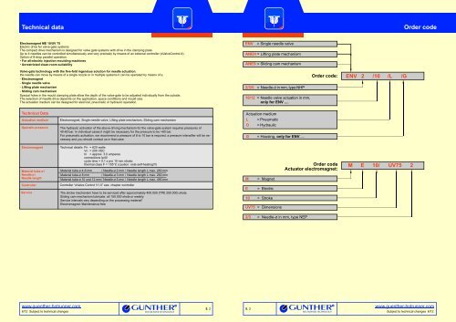
ENV = Single needle valve<br />
ANEH = Lifting plate <strong>mechanism</strong><br />
<strong>ANES</strong> = <strong>Sliding</strong> <strong>cam</strong> <strong>mechanism</strong><br />
2/3/5 = Needle-Ø in mm, <strong>type</strong> NHP<br />
10/12 = Needle valve actuation in mm,<br />
only for ENV ....<br />
Actuation medium<br />
L<br />
O<br />
= Pneumatic<br />
= Hydraulic<br />
G = Housing, only for ENV.....<br />
M = Magnet<br />
E = Electric<br />
10 = Stroke<br />
UV75 = Dimensions<br />
2/3 = Needle-Ø in mm, <strong>type</strong> NEP<br />
Order code<br />
Actuator electromagnet:<br />
Order code: ENV 2 /10 /L /G<br />
M E 10/ UV75 2<br />
Order code<br />
www.guenther-hotrunner.com<br />
Subject to technical changes 6/12
Materialabhängige Materialabhängige Düsenauswahl<br />
Düsenauswahl<br />
Hinweise<br />
a. The needle valve is coated.<br />
Blanks are available for needle valve used in special<br />
applications (e. g. exceptional lengths, gate diameter, pin diameter<br />
etc.)<br />
b.<br />
Please note<br />
c. The needle length is dependent on the nozzle length,<br />
the<br />
<strong>mechanism</strong> and the assembly of the manifold.<br />
e. Thread tightening torque to (NHP) needle adjustment<br />
Following parts must be ordered separately. Box spanner - two parts<br />
to adjust the needles, chapter 8.<br />
5. 4<br />
Needle adjustment or changing results through clampingplate/<br />
lifting plate without disassembly of the tools.<br />
d. Maximum tightening torque<br />
Regelgewinde<br />
Threads<br />
M4<br />
M5<br />
M6<br />
M8<br />
M10<br />
M12<br />
Needle-Ø<br />
Ø 2 mm<br />
Ø 3 mm<br />
Ø 5 mm<br />
Needle-Ø Thread<br />
Order code<br />
Strength class<br />
10.9 12.9<br />
3.8 Nm<br />
8 Nm<br />
13 Nm<br />
32 Nm<br />
64 Nm<br />
110 Nm<br />
Thread Tightening torque<br />
M A [Nm]<br />
M6 x 0.50<br />
15<br />
M8 x 0.50<br />
M10 x 0.75<br />
f. Thread tightening torque to (NEP) needle adjustment<br />
Ø 2 mm<br />
Ø 3 mm<br />
M6 x 0.50<br />
M8 x 0.50<br />
Bei If you Fragen have wenden any questions Sie sich please bitte an call die our technical consulting,<br />
Technische at +49 (0) 6451 Anwendungsberatung, - 50 08 0.<br />
Tel.: +49 (0) 6451 - 50 08 0.<br />
30<br />
45<br />
15<br />
30<br />
4.6 Nm<br />
9.5 Nm<br />
16.0 Nm<br />
39.0 Nm<br />
77.0 Nm<br />
135.0 Nm<br />
Tightening torque<br />
M [Nm]<br />
A<br />
ME electromagnet<br />
Hinweise Notes<br />
ME 10/UV 75 electric drive for valve-gates<br />
The ME 10 bistable heavy-duty lifting magnet serves to actuate valve<br />
needles in valve-gate systems.<br />
Excellent for all-electric injection moulding machines and for cleanroom<br />
applications.<br />
Available voltages are 48 VDC and 205 VDC (approx. 10 A and 2.5 A<br />
per magnet accordingly). The magnet is designed for thermal class F<br />
(155° C). The heat balance must be checked in individual cases,<br />
taking self-heating and heat dissipation into account.<br />
ENV single needle valve<br />
Needle actuation in single and multiple systems. Sequential opening<br />
and closing of the needles. Special holes in the mould clamping plate<br />
allow the down-stroke depth of the valve gate to be adjusted individually<br />
from the outside. Maximum working temperature is 100° C.<br />
1<br />
2<br />
3<br />
4<br />
5<br />
6<br />
Tempering<br />
Sufficient cooling must be ensured in the lower area of needle<br />
actuation. We also urgently recommend cooling the clamping<br />
plate and frame plates or risers.<br />
Assembly height<br />
The assembly height is dependend on the dimension of the<br />
manifold height linked to the cable-Ø, the balanced and the use of<br />
nozzle <strong>type</strong>.<br />
Single needle valve<br />
ENV2/10/L, ENV2/10/L/G, ENV2/10/O, ENV2/10/O/G,(56 mm),<br />
ENV3/10/L, ENV3/10/L/G, ENV3/10/O, ENV3/10/O/G (56 mm),<br />
ENV5/12/L, ENV5/12/L/G, ENV5/12/O, ENV5/12/O/G (66 mm)<br />
Contour in details without housing<br />
In the area of the piston stroke, the surface of the cylinder hast to<br />
be flash-free and without sharp edges. Piston operating surface are<br />
honed or rolled (Ra min. 0.2).<br />
Contour in details without housing<br />
ENV2 und ENV3 ENV5<br />
R0.5<br />
R0.5<br />
3<br />
0.4<br />
0.2<br />
Edge<br />
15°<br />
Piston operating<br />
surface<br />
Ra min. 0.2<br />
Contour in details with housing<br />
0.4<br />
Edge<br />
deburred<br />
15°<br />
1.6<br />
R0.5<br />
R0.5<br />
Access supplied by the customer in the area of the fastening screw M5.<br />
4<br />
0.2<br />
7 Threads/ counterbore/ cylinder head screw<br />
ENV2/ ENV3<br />
a. Thread/ counterbore 45° rotated shown<br />
b. 4x counterbore DIN 974-1<br />
c. 4x cylinder screw M5 x 20 - 12.9 DIN EN ISO 4762<br />
ENV5<br />
a. Thread/ counterbore 30° rotated shown<br />
b. 6x counterbore DIN 974-1<br />
c. 6x cylinder screw M6 x 25 - 12.9 DIN EN ISO 4762<br />
ANEH lifting plate <strong>mechanism</strong><br />
Hinweise Notes<br />
The lifting <strong>mechanism</strong> is recommendable for a precisely<br />
simultaneous opening and closing of all needles.<br />
Special holes in the mould clamping plate allow the down-stroke depth<br />
of the valve needles to be adjusted individually from the outside.<br />
The maximum working temperature is 100° C.<br />
10<br />
11<br />
12<br />
13<br />
14<br />
15<br />
16<br />
17<br />
18<br />
19<br />
20<br />
21<br />
22<br />
23<br />
24<br />
Valve-gate nozzle, chapter 2.3<br />
The valve needle is not a component part of the valve-gate nozzle,<br />
chapter 8<br />
Manifold, chapter 4<br />
Needle guide<br />
Adjust wrench<br />
Covering<br />
Socket wrenches to adjust the valve needle, chapter 8<br />
Needle movement (stroke)<br />
Needle movement (stroke) of 10 mm is provided for nozzles<br />
with material tube-Ø (Ød) of 4-6 mm.<br />
Needle movement (stroke) of 12 mm is provided for nozzles<br />
with material tube-Ø (Ød) of 8-12 mm.<br />
Clamping plate with<br />
Supporting plate<br />
Nozzle holding plate<br />
Support pieces<br />
Guiding unit incl. guide pillar<br />
Adapter (ball)<br />
Cylinder<br />
<strong>ANES</strong> sliding <strong>cam</strong> <strong>mechanism</strong><br />
For narrow cavity spacing a sliding <strong>cam</strong> <strong>mechanism</strong> is the preferred<br />
drive.<br />
Exact opening and closing of all needles.<br />
Special holes in the mould clamping plate allow the down-stroke<br />
depth of the valve gate to be adjusted individually from the outside.<br />
Maximum working temperature is 100° C.<br />
www.guenther-hotrunner.com<br />
Subject to technical changes 6/12
<strong>Sliding</strong> <strong>cam</strong> <strong>mechanism</strong> <strong>type</strong> <strong>ANES</strong>/ L - <strong>ANES</strong>/ O<br />
Order code<br />
Example: <strong>ANES</strong>/L <strong>Sliding</strong><br />
<strong>cam</strong> <strong>mechanism</strong><br />
<strong>ANES</strong> = <strong>Sliding</strong> <strong>cam</strong> <strong>mechanism</strong><br />
L = Actuation medium: pneumatic<br />
Please indicate the actuation medium and<br />
mold dimensions in your order.<br />
Notes<br />
With tight pitches of 9-12 mm, please use the<br />
sliding <strong>cam</strong> <strong>mechanism</strong> for needle actuation.<br />
Accurate opening and closing of all needles<br />
Maximum working temperature of 100°C<br />
a Floating bearings for valve-gates<br />
Details are dependent on the actuation medium<br />
and mold size.<br />
If you have further questions please do not<br />
hesitate to contact our engineering<br />
department at +49 (0) 6451 - 50 08 0.<br />
a<br />
14<br />
Needle-Ø 2 mm = Ø8<br />
Needle-Ø 3 mm = Ø10<br />
Needle-Ø 5 mm = Ø15<br />
Signs and symbols, detailed on the yellow page:<br />
12<br />
13<br />
14<br />
15<br />
Needle<br />
Needle holder<br />
Adjusting screw nut<br />
Cover<br />
16<br />
17<br />
18<br />
19<br />
www.guenther-hotrunner.com<br />
6/12 Subject to technical changes<br />
15<br />
13<br />
12<br />
Socket wrenches<br />
Needle holding<br />
Clamping plate<br />
Lifting plate<br />
21<br />
20<br />
20<br />
21<br />
22<br />
23<br />
22<br />
19<br />
18<br />
23<br />
17<br />
Slide plate<br />
Slide bar<br />
Actuation<br />
Stop<br />
16<br />
Special openings in the clamping plate allow<br />
an individual adjustment of the valve-gate<br />
needle from the outside<br />
24<br />
25<br />
Cover plate<br />
Control rail<br />
24<br />
25<br />
5. 70<br />
<strong>ANES</strong>/ L ANEH/L<br />
<strong>ANES</strong>/ O ANEH/O<br />
ENV5/L ENV2/3/O ENV2/3/L ME 10/UV75