SQ-XLD
SQ-XLD
SQ-XLD

You also want an ePaper? Increase the reach of your titles
YUMPU automatically turns print PDFs into web optimized ePapers that Google loves.
DATASHEET<br />
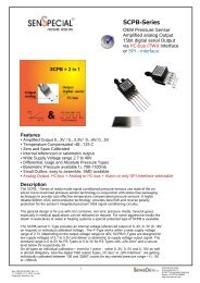
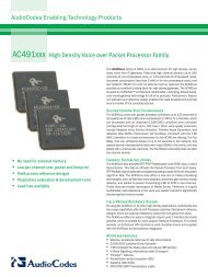
<strong>SQ</strong>-<strong>XLD</strong><br />
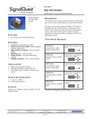
MEMS ACCELEROMETER<br />
2 & 3 AXIS, SERIAL OUTPUT, CALIBRATED, 1.7 G, 5 G, 18 G, 35 G, 50 G, 70 G<br />
<strong>SQ</strong>-<strong>XLD</strong>-2X <strong>SQ</strong>-<strong>XLD</strong>-3X USB to TTL Cable<br />
(RS232 version available)<br />
SignalVIEW software<br />
DESCRIPTION<br />
The acceleration sensor module performs calibrated<br />
acceleration measurement with digital serial output.<br />
Using a USB or RS232 interface cable (sold separately), it<br />
functions as a self contained data acquisition system for 2<br />
axis or 3 axis acceleration, tilt, and vibration<br />
measurement.<br />
The PC data acquisition interface software called<br />
SignalVIEW is written in the popular LabVIEW visual<br />
programming language. This offers an easy, menu-driven<br />
data acquisition PC interface. The user can configure<br />
various parameters of the sensor such as sample rate, and<br />
digital filter parameters. More advanced functions such as<br />
post processing, analysis, and algorithm prototyping can<br />
be added directly into the console source code. By<br />
coupling real-time data acquisition with real- time<br />
graphical display and signal processing, the <strong>SQ</strong>-<strong>XLD</strong><br />
series accelerometer makes an ideal platform for real time<br />
monitoring or prototyping accelerometer systems.<br />
FUNCTION<br />
• Miniature, low-cost, serial accelerometer<br />
• Real-time data acquisition performance using a low<br />
cost serial cable<br />
• Simple menu-driven PC configuration of sampling<br />
parameters<br />
• Adjustable sample rate and filtering in software<br />
FEATURES<br />
• ± 1.7 g to ±70g models available<br />
• 2.5% accuracy, factory calibrated<br />
• 2 or 3 axis models<br />
• 10 Hz to 1 kHz sampling<br />
• 10 to 13 bit resolution<br />
• DC through 1 kHz bandwidth<br />
• Direct PC interface cable<br />
APPLICATIONS<br />
• Low cost data acquisition<br />
• Real time system monitoring<br />
• Motion, tilt, shock and vibration analysis<br />
• Industrial process control<br />
Updated: 2008-06-04<br />
© SignalQuest, Inc.<br />
1999-2008<br />
10 Water St.<br />
Lebanon, NH 03766 USA<br />
Tel: 603.448.6266<br />
Fax 603.619.6330<br />
www.signalquest.com<br />
info@signalquest.com<br />
Page 1 of 14
DATASHEET<br />
<strong>SQ</strong>-<strong>XLD</strong><br />
MEMS ACCELEROMETER<br />
2 & 3 AXIS, SERIAL OUTPUT, CALIBRATED, 1.7 G, 5 G, 18 G, 35 G, 50 G, 70 G<br />
TABLE OF CONTENTS<br />
Description...................................................................................................................................................................................1<br />
Function.......................................................................................................................................................................................1<br />
Features........................................................................................................................................................................................1<br />
Applications.................................................................................................................................................................................1<br />
Absolute Maximum Ratings ........................................................................................................................................................3<br />
Electrical Characteristics .............................................................................................................................................................3<br />
Electrical Characteristics .............................................................................................................................................................3<br />
Pin Configuration.........................................................................................................................................................................4<br />
<strong>SQ</strong>-<strong>XLD</strong> 2 Axis Packages............................................................................................................................................................5<br />
Dimensions ..................................................................................................................................................................................5<br />
<strong>SQ</strong>-<strong>XLD</strong> 2 Axis Package .............................................................................................................................................................6<br />
Dimensions ..................................................................................................................................................................................6<br />
Design, Layout, and Assembly Considerations ...........................................................................................................................7<br />
Reset Sources...............................................................................................................................................................................7<br />
Serial Interface.............................................................................................................................................................................8<br />
SignalVIEW Software Basic......................................................................................................................................................11<br />
Ordering Guide ..........................................................................................................................................................................13<br />
Accessories ................................................................................................................................................................................13<br />
Limitations and Warnings..........................................................................................................................................................14<br />
Testing .......................................................................................................................................................................................14<br />
System Integration Testing ........................................................................................................................................................14<br />
Updated: 2008-06-04<br />
© SignalQuest, Inc.<br />
1999-2008<br />
10 Water St.<br />
Lebanon, NH 03766 USA<br />
Tel: 603.448.6266<br />
Fax 603.619.6330<br />
www.signalquest.com<br />
info@signalquest.com<br />
Page 2 of 14
DATASHEET<br />
<strong>SQ</strong>-<strong>XLD</strong><br />
MEMS ACCELEROMETER<br />
2 & 3 AXIS, SERIAL OUTPUT, CALIBRATED, 1.7 G, 5 G, 18 G, 35 G, 50 G, 70 G<br />
ABSOLUTE MAXIMUM RATINGS<br />
PARAMETER MIN TYPICAL MAX NOTES<br />
Voltage on +Vcc 0.3 V 5.8 V with respect to GND<br />
Voltage on any input pin 5.8 V with respect to GND<br />
Peak-to-peak supply noise<br />
200 mV<br />
Operating temperature -40 º C 85 º C<br />
Shock survivability<br />
500 g<br />
where 1 g is assumed<br />
to be = 9.81 m/s 2<br />
Note: Exposure to conditions outside of the Absolute Maximum Ratings may damage the device. Prolonged exposure to<br />
conditions at the Absolute Maximum Ratings may result in degraded performance of the device over time.<br />
ELECTRICAL CHARACTERISTICS<br />
[Test conditions: 3.3v regulator, 25 º C unless otherwise specified]<br />
PARAMETER MIN TYPICAL MAX NOTES<br />
Supply voltage 3.5 V 5.8 V with respect to GND<br />
Supply current 1.6 mA 6.0 mA<br />
Input voltage High<br />
2.0 V<br />
Input voltage Low<br />
0.8 V<br />
Output voltage High 0.895 × Vcc Vcc<br />
Output voltage Low 0 V 0.100 × Vcc<br />
PERFORMANCE CHARACTERISTICS<br />
[Test conditions: 3.3v regulator, 25 º C unless otherwise specified]<br />
PARAMETER MIN NOTES<br />
Acceleration range** ±1.5 g to ±50 g with respect to GND<br />
Accelerometer resolution**<br />
Alignment accuracy<br />
± 2º<br />
Sample rate<br />
1000 Hz<br />
Accelerometer bandwidth DC – 1 KHz (configurable from 10<br />
Hz to 1 KHz in<br />
software using moving<br />
average)<br />
Serial communication<br />
115,700 baud<br />
Temperature sensitivity **<br />
**Available using various Analog Device accelerometers including ADXL203, ADXL103, ADXL320, ADXL330,<br />
ADXL210, ADXL78, and ADXL278 please visit www.analog.com for more information.<br />
Updated: 2008-06-04<br />
© SignalQuest, Inc.<br />
1999-2008<br />
10 Water St.<br />
Lebanon, NH 03766 USA<br />
Tel: 603.448.6266<br />
Fax 603.619.6330<br />
www.signalquest.com<br />
info@signalquest.com<br />
Page 3 of 14
DATASHEET<br />
<strong>SQ</strong>-<strong>XLD</strong><br />
MEMS ACCELEROMETER<br />
2 & 3 AXIS, SERIAL OUTPUT, CALIBRATED, 1.7 G, 5 G, 18 G, 35 G, 50 G, 70 G<br />
PIN CONFIGURATION<br />
PIN SIGNAL NAME USAGE<br />
1 Ground<br />
2 UART Transmit Digital Output – UART transmit line. Push-pull (not open collector). If not used, solder to<br />
open circuit for mechanical stability. Do not connect to GND or current drain will increase.<br />
3 UART Receive Digital Input – UART receive line. If not used, solder to V+.<br />
4 NC Solder to open circuit for mechanical stability. Do not connect to GND<br />
5 +Vcc Supply<br />
6 NC Solder to open circuit for mechanical stability. Do not connect to GND<br />
7 NC Solder to open circuit for mechanical stability. Do not connect to GND<br />
8 NC Solder to open circuit for mechanical stability. Do not connect to GND<br />
9 NC Solder to open circuit for mechanical stability. Do not connect to GND<br />
10 NC Solder to open circuit for mechanical stability. Do not connect to GND.<br />
11 NC Solder to open circuit for mechanical stability. Do not connect to GND<br />
12 NC Solder to open circuit for mechanical stability. Do not connect to GND<br />
13 NC Solder to open circuit for mechanical stability. Do not connect to GND<br />
14 NC Solder to open circuit for mechanical stability. Do not connect to GND<br />
15 /Reset & Prog 1 Digital Input – Active low reset. Bring low for >10 mS to reset device. If not used, solder<br />
to open circuit for mechanical stability. Do not connect to GND. Also used for FLASH<br />
programming.<br />
16 Prog 2 Digital Input – If not used, solder to open circuit for mechanical stability. Do not connect to<br />
GND. Also used for FLASH programming.<br />
17 NC Solder to open circuit for mechanical stability. Do not connect to GND<br />
18 NC Solder to open circuit for mechanical stability. Do not connect to GND<br />
*Note: Grey boxes indicate a function is available only on a custom application basis. NC means “no connection”.<br />
Updated: 2008-06-04<br />
© SignalQuest, Inc.<br />
1999-2008<br />
10 Water St.<br />
Lebanon, NH 03766 USA<br />
Tel: 603.448.6266<br />
Fax 603.619.6330<br />
www.signalquest.com<br />
info@signalquest.com<br />
Page 4 of 14
DATASHEET<br />
<strong>SQ</strong>-<strong>XLD</strong><br />
MEMS ACCELEROMETER<br />
2 & 3 AXIS, SERIAL OUTPUT, CALIBRATED, 1.7 G, 5 G, 18 G, 35 G, 50 G, 70 G<br />
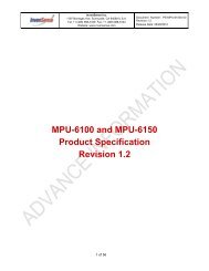
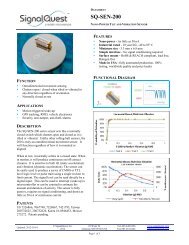
<strong>SQ</strong>-<strong>XLD</strong> 2 AXIS PACKAGES<br />
DIMENSIONS<br />
DIMENSION MILLIMETERS INCHES DESCRIPTION NOTES<br />
T 10.16 0.40 N/A Pin center to center<br />
L 25.40 1.00 Side length<br />
E 2.54 0.10 Pitch Pin center to center<br />
D 0.80 0.032 Pin diameter<br />
DD 1.00 0.040 Hole diameter<br />
N 1.63 0.064 PCB thickness<br />
S 20.32 0.80 Pin row spacing Not shown on drawing<br />
Updated: 2008-06-04<br />
© SignalQuest, Inc.<br />
1999-2008<br />
10 Water St.<br />
Lebanon, NH 03766 USA<br />
Tel: 603.448.6266<br />
Fax 603.619.6330<br />
www.signalquest.com<br />
info@signalquest.com<br />
Page 5 of 14
DATASHEET<br />
<strong>SQ</strong>-<strong>XLD</strong><br />
MEMS ACCELEROMETER<br />
2 & 3 AXIS, SERIAL OUTPUT, CALIBRATED, 1.7 G, 5 G, 18 G, 35 G, 50 G, 70 G<br />
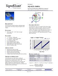
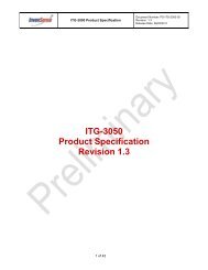
<strong>SQ</strong>-<strong>XLD</strong> 3 AXIS PACKAGE<br />
DIMENSIONS<br />
DIMENSION MILLIMETERS INCHES DESCRIPTION NOTES<br />
T 10.16 0.40 N/A Pin center to center<br />
L 25.40 1.00 Side length<br />
E 2.54 0.10 Pitch Pin center to center<br />
D 0.80 0.032 Pin diameter<br />
DD 1.00 0.040 Hole diameter<br />
N 1.63 0.064 PCB thickness<br />
H 8.64 0.34 Ortho board height<br />
P 3.30 0.13 N/A<br />
S 20.32 0.80 Pin row spacing Same as ortho board width<br />
Updated: 2008-06-04<br />
© SignalQuest, Inc.<br />
1999-2008<br />
10 Water St.<br />
Lebanon, NH 03766 USA<br />
Tel: 603.448.6266<br />
Fax 603.619.6330<br />
www.signalquest.com<br />
info@signalquest.com<br />
Page 6 of 14
DATASHEET<br />
<strong>SQ</strong>-<strong>XLD</strong><br />
MEMS ACCELEROMETER<br />
2 & 3 AXIS, SERIAL OUTPUT, CALIBRATED, 1.7 G, 5 G, 18 G, 35 G, 50 G, 70 G<br />
DESIGN, LAYOUT, AND ASSEMBLY CONSIDERATIONS<br />
1. Since the device is a subassembly of surface mount components, it is not suitable for automatic assembly or wave<br />
soldering.<br />
2. Hand soldering of pins or SMT pads is specified for 3 seconds at 218 ºC.<br />
3. Pins labeled NC (no connect) should be soldered to open connection pads / pins for mechanical stability.<br />
4. The designer should test the device’s output voltage through its entire desired angle range during prototyping to<br />
ensure that it is working properly in the application.<br />
5. The device can be mounted vertically or horizontally, but the direction must be oriented correctly to measure the<br />
desired angles.<br />
6. It is recommended that pins designated “future” be connected for forward compatibility.<br />
RESET SOURCES<br />
Power-on Reset and RST pin<br />
When the inclinometer is disconnected from power it reverts to its default settings in Interrogate Mode. It transmits 1 data<br />
packet [10 bytes] after its Warm Up time to indicate that measurements are stabilized.<br />
Updated: 2008-06-04<br />
© SignalQuest, Inc.<br />
1999-2008<br />
10 Water St.<br />
Lebanon, NH 03766 USA<br />
Tel: 603.448.6266<br />
Fax 603.619.6330<br />
www.signalquest.com<br />
info@signalquest.com<br />
Page 7 of 14
DATASHEET<br />
<strong>SQ</strong>-<strong>XLD</strong><br />
MEMS ACCELEROMETER<br />
2 & 3 AXIS, SERIAL OUTPUT, CALIBRATED, 1.7 G, 5 G, 18 G, 35 G, 50 G, 70 G<br />
SERIAL INTERFACE<br />
A single command can set most commonly-used functions of the device. This is done by sending a new Command Byte to<br />
the device. The lower 7 bits (BIT6 through BIT0) are orthogonal, and hence, have no effect on one another. They can be<br />
combined together by adding bits to form single command. All Orthogonal Commands have the Special Function Bit (BIT7)<br />
set to 0.<br />
After each data packet is transmitted, the device returns to its minimum current state until another command is received.<br />
UART FORMAT: 8-N-1<br />
8 data bits, 1 stop bit, no parity, no flow control: 115,700 baud<br />
One byte commands can be sent from the host to control various functions of the device. The following commands can be<br />
sent to the devices via the UART. The data encoding is HEX, not ASCII.<br />
FILTER CONTROL<br />
A digital moving average filter can be enabled with lengths of 2, 10, or 100 points. This feature is useful in reducing noise<br />
and improving resolution with little or no impact on power consumption. Each time the device acquires a data point, this<br />
moving average is updated. Switching the moving average setting causes the entire filter to be initialized with the first new<br />
data value. The time constant of the filter depends on the speed at which samples are requested by the host.<br />
SPECIAL FUNCTION COMMAND OVERVIEW<br />
All Special Function Commands have the Special Function Bit (BIT7) set to 1. The lower bits of any Command Byte sent to<br />
the device are ignored when a Special Function Command is used.<br />
TIMING<br />
New commands should not be sent from the host faster than Sample Rate to avoid overwriting previous commands. The<br />
recommend method to ensure that this does not occur is to send commands in Interrogate Mode and then wait for the<br />
response packet before issuing a new command.<br />
RESET SOURCES<br />
Grounding the device’s power pin for 200 mS will reset the device. When the device is powered on, it will revert to its<br />
default settings. On power up, a single measurement is taken and a single data packet is transmitted. Alternatively, the Reset<br />
Command may be used to force a reset.<br />
Updated: 2008-06-04<br />
© SignalQuest, Inc.<br />
1999-2008<br />
10 Water St.<br />
Lebanon, NH 03766 USA<br />
Tel: 603.448.6266<br />
Fax 603.619.6330<br />
www.signalquest.com<br />
info@signalquest.com<br />
Page 8 of 14
DATASHEET<br />
<strong>SQ</strong>-<strong>XLD</strong><br />
MEMS ACCELEROMETER<br />
2 & 3 AXIS, SERIAL OUTPUT, CALIBRATED, 1.7 G, 5 G, 18 G, 35 G, 50 G, 70 G<br />
COMMAND BYTE<br />
BITS USE BINARY HEX COMMAND RESPONSE NOTES<br />
Bits[5:4]<br />
Bit[6] Bit[7]<br />
Special<br />
Commands<br />
Reserved for<br />
future use<br />
Reserved for future<br />
use<br />
1000 0011 0x83 Reset Device reset<br />
01xx xxx<br />
00xx xxx<br />
0x11 xxxx<br />
0x10 xxxx<br />
0x01 xxxx<br />
0x00 xxxx<br />
0x40<br />
NA<br />
0x30<br />
0x20<br />
0x10<br />
NA<br />
Reserved for<br />
future use<br />
Reserved for<br />
future use<br />
Reserved for<br />
future use<br />
Reserved for<br />
future use<br />
Reserved for<br />
future use<br />
Reserved for<br />
future use<br />
0xxx 11xx 0x0C Average 100<br />
Undefined<br />
Undefined<br />
Undefined<br />
Undefined<br />
Undefined<br />
Undefined<br />
Moving average length<br />
set to 100 points<br />
Example: Acquire 1<br />
packet as fast as possible –<br />
Combine Interrogate Mode<br />
(0x01) and Average 0<br />
(0x00). To do this, send<br />
0x01. The response will be<br />
1 data packet after a delay<br />
of 1/Sample Rate seconds.<br />
Example: Stream packets<br />
with a 10 point moving<br />
average –<br />
Combine Stream Mode<br />
(0x02) and Average 10<br />
(0x08). To do this, send<br />
0x0A (formed by adding<br />
0x02 + 0x08). The<br />
response will be 1 data<br />
packet after a delay of<br />
1/(10*Sample Rate)<br />
seconds.<br />
Bits[3:2]<br />
Filter Control<br />
0xxx 10xx 0x08 Average 10<br />
0xxx 01xx 0x04 Average 2<br />
Moving average length<br />
set to 10 points<br />
Moving average length<br />
set to 2 points<br />
0xxx 00xx<br />
NA<br />
Average 0<br />
(default)<br />
No moving average<br />
filtering<br />
Bits[1:0]<br />
Output Control<br />
0xxx xx11<br />
0x03<br />
Reserved for<br />
future use<br />
0xxx xx10 0x02 Stream Mode<br />
0xxx xx01<br />
0x01<br />
Interrogate Mode<br />
(default)<br />
Undefined<br />
Replies by streaming<br />
packets at Sample Rate<br />
/ Average Control<br />
packets per second<br />
Replies with single<br />
data packet<br />
0xxx xx00<br />
0x00<br />
Reserved for<br />
future use<br />
Undefined<br />
Updated: 2008-06-04<br />
© SignalQuest, Inc.<br />
1999-2008<br />
10 Water St.<br />
Lebanon, NH 03766 USA<br />
Tel: 603.448.6266<br />
Fax 603.619.6330<br />
www.signalquest.com<br />
info@signalquest.com<br />
Page 9 of 14
DATASHEET<br />
<strong>SQ</strong>-<strong>XLD</strong><br />
MEMS ACCELEROMETER<br />
2 & 3 AXIS, SERIAL OUTPUT, CALIBRATED, 1.7 G, 5 G, 18 G, 35 G, 50 G, 70 G<br />
SERIAL PACKET FORMAT<br />
BYTE DESCRIPTION NOTES<br />
Header<br />
0 Sync byte 1 0xFE<br />
1 Sync byte 2 0xFE<br />
2<br />
X Acceleration<br />
(high byte)<br />
Payload<br />
3<br />
4<br />
5<br />
6<br />
X Acceleration<br />
(low byte)<br />
Y Acceleration<br />
(high byte)<br />
Y Acceleration<br />
(low byte)<br />
Z Acceleration<br />
(high byte)<br />
Format: 16-bit, unsigned integer.<br />
Output_Value = Acceleration (g)*1000.<br />
For example, a measured acceleration of 0.851 g results in an output value<br />
of 851.<br />
If no Z axis is present, the values are undefined.<br />
7<br />
Z Acceleration<br />
(low byte)<br />
Checksum<br />
8 Checksum (high)<br />
9 Checksum (low)<br />
Format: 16-bit, unsigned integer sum of the 16 bit unsigned integer payload<br />
values. The checksum does not include the two sync bytes (0xFE 0xFE).<br />
Updated: 2008-06-04<br />
© SignalQuest, Inc.<br />
1999-2008<br />
10 Water St.<br />
Lebanon, NH 03766 USA<br />
Tel: 603.448.6266<br />
Fax 603.619.6330<br />
www.signalquest.com<br />
info@signalquest.com<br />
Page 10 of 14
DATASHEET<br />
<strong>SQ</strong>-<strong>XLD</strong><br />
MEMS ACCELEROMETER<br />
2 & 3 AXIS, SERIAL OUTPUT, CALIBRATED, 1.7 G, 5 G, 18 G, 35 G, 50 G, 70 G<br />
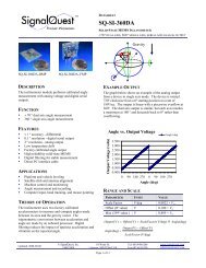
SIGNALVIEW SOFTWARE BASIC<br />
OVERVIEW<br />
■ The SignalVIEW software is designed to be used with SignalQuest’s <strong>SQ</strong>-<strong>XLD</strong> series products<br />
■ The easy to use, LabVIEW interface provides a real-time interface for the data acquisition system.<br />
■ Allows users to configure sampling parameters, view and analyze data, save waveforms, and export data values to a<br />
spreadsheet or text editor.<br />
SAMPLING AND LOGGING<br />
■ This area provides the interface for capturing data from the <strong>SQ</strong>-<strong>XLD</strong> device.<br />
■ Select effective sample rate and ports.<br />
■ Access additional tools to zoom, pan, and change history length.<br />
Updated: 2008-06-04<br />
© SignalQuest, Inc.<br />
1999-2008<br />
10 Water St.<br />
Lebanon, NH 03766 USA<br />
Tel: 603.448.6266<br />
Fax 603.619.6330<br />
www.signalquest.com<br />
info@signalquest.com<br />
Page 11 of 14
DATASHEET<br />
<strong>SQ</strong>-<strong>XLD</strong><br />
MEMS ACCELEROMETER<br />
2 & 3 AXIS, SERIAL OUTPUT, CALIBRATED, 1.7 G, 5 G, 18 G, 35 G, 50 G, 70 G<br />
VIEWING SAVED DATA<br />
■ This area provides the interface for viewing and analyzing saved data<br />
■ Data values can be exported to a spreadsheet or text editor or saved as a waveform for future analysis.<br />
■ Access additional tools to zoom, pan, and change history length.<br />
Updated: 2008-06-04<br />
© SignalQuest, Inc.<br />
1999-2008<br />
10 Water St.<br />
Lebanon, NH 03766 USA<br />
Tel: 603.448.6266<br />
Fax 603.619.6330<br />
www.signalquest.com<br />
info@signalquest.com<br />
Page 12 of 14
DATASHEET<br />
<strong>SQ</strong>-<strong>XLD</strong><br />
MEMS ACCELEROMETER<br />
2 & 3 AXIS, SERIAL OUTPUT, CALIBRATED, 1.7 G, 5 G, 18 G, 35 G, 50 G, 70 G<br />
ORDERING GUIDE<br />
OPTIONS CODE OPTION NOTES<br />
Axes<br />
-2X 2 axis<br />
-3X 3 axis<br />
Range<br />
Package<br />
Options<br />
-1.7G<br />
1.7 g<br />
-5.0G 5 g Special order only.<br />
-18G 18 g Special order only.<br />
-35G 35 g Special order only.<br />
-50G 50 g Special order only.<br />
-70G 70 g Special order only.<br />
-NP No pins 2 axis version fits inside potting box enclosures (<strong>SQ</strong>-ENCL-1).<br />
3 axis version requires 2 potting boxes.<br />
-HMP Horizontal mount pins<br />
-E RoHS complaint, lead free<br />
Other<br />
option<br />
RoHS<br />
(lead free)<br />
-Custom<br />
Customer-specific<br />
requirements<br />
Please contact SignalQuest if you require an option not listed in this<br />
table. For example, various baud rates, setting times, update rates and<br />
voltage regulator options may be available on request.<br />
EXAMPLE PART NUMBER<br />
<strong>SQ</strong>-<strong>XLD</strong>-2X-1.7G-NP<br />
ACCESSORIES<br />
PART NUMBER<br />
DESCRIPTION<br />
<strong>SQ</strong>-USB2-TTL ■ Self-powering USB cable used to directly connect device to a PC.<br />
■ Installs a “virtual COM port” on host PC (i.e. COM 3).<br />
■ Converts PC voltage levels to device voltage levels and supplies power.<br />
■ Allows multiple devices to be easily connected to a single computer.<br />
■ Compatible with SignalVIEW real time display and data logging software.<br />
■ DLL provide for custom application development in VC++, C#, or VB etc.<br />
<strong>SQ</strong>-RS232-TTL ■ Same as above cable, but external power is required for devices without –LP option.<br />
<strong>SQ</strong>-ENCL-1 ■ Potting box enclosure. Potting box enclosure. Fits models without pins installed (-NP option).<br />
Order one if using <strong>SQ</strong>-<strong>XLD</strong>-2X family or two if ordering <strong>SQ</strong>-<strong>XLD</strong>-3X family.<br />
Updated: 2008-06-04<br />
© SignalQuest, Inc.<br />
1999-2008<br />
10 Water St.<br />
Lebanon, NH 03766 USA<br />
Tel: 603.448.6266<br />
Fax 603.619.6330<br />
www.signalquest.com<br />
info@signalquest.com<br />
Page 13 of 14
DATASHEET<br />
<strong>SQ</strong>-<strong>XLD</strong><br />
MEMS ACCELEROMETER<br />
2 & 3 AXIS, SERIAL OUTPUT, CALIBRATED, 1.7 G, 5 G, 18 G, 35 G, 50 G, 70 G<br />
LIMITATIONS AND WARNINGS<br />
LIFE SAFETY<br />
This product is not designed for use in life support and/or safety equipment where malfunction of the product can reasonably<br />
be expected to result in personal injury or death. Buyer uses this product in such applications at Buyer’s own risk and agrees<br />
to defend, indemnify, and hold harmless SignalQuest, Inc. from any and all damages, claims, suits, or expenses resulting from<br />
such misuse.<br />
DYNAMIC ENVIRONMENTS<br />
The device is designed to be used to measure angles in a quasi-static environment where external vibrations and accelerations<br />
are kept to a minimum. Digital and analog signal processing methods are employed to reduce the effects of transient<br />
acceleration and small vibrations on the angle reading; however, under dynamic conditions where external accelerations or<br />
vibrations are present, the sensor’s performance may be degraded.<br />
VARIATIONS IN EARTH’S GRAVITY<br />
This device is designed to be used near the earth’s surface only. Substantial changes in gravity will degrade the performance<br />
of the sensor. This device is not intended or qualified to be used in aviation.<br />
TESTING<br />
The performance of each system is verified through build-time testing. Each system is tested before and after factory<br />
calibration to ensure reliable performance.<br />
SYSTEM INTEGRATION TESTING<br />
Thorough testing should be carried out prior to product release to insure system integration has not introduced unforeseen<br />
problems. The system integrator assumes the ultimate responsibility for the safety of the target application.<br />
NOTICE<br />
Information furnished by SignalQuest, Inc is believed to be accurate and reliable. However, this document may contain<br />
ERRORS and OMMISIONS. Accordingly, the design engineer should use this document as a reference rather than a strict<br />
design guideline and should perform thorough testing of any product that incorporates this or any other SignalQuest product.<br />
No responsibility is assumed by SignalQuest, Inc. for this use of this information, or for any infringements of patents or other<br />
rights of third parties that may result from its use. Specifications are subject to change without notice. No license is granted<br />
by implication or otherwise under any patent or patent rights of SignalQuest, Inc. Trademarks and registered trademarks are<br />
the property of their respective companies.<br />
FURTHER INFORMATION<br />
For pricing, delivery, and ordering information, please contact SignalQuest at (603) 448-6266<br />
For updates on this and other documents, visit our website at www.signalquest.com<br />
Updated: 2008-06-04<br />
© SignalQuest, Inc.<br />
1999-2008<br />
10 Water St.<br />
Lebanon, NH 03766 USA<br />
Tel: 603.448.6266<br />
Fax 603.619.6330<br />
www.signalquest.com<br />
info@signalquest.com<br />
Page 14 of 14