section d - Total Hydraulics BV
section d - Total Hydraulics BV
section d - Total Hydraulics BV

Create successful ePaper yourself
Turn your PDF publications into a flip-book with our unique Google optimized e-Paper software.
Hydrauliek<br />
Pneumatiek<br />
Aandrijftechniek<br />
HEERHUGOWAARD . T: +31 (0)72 57 66 700 . WWW.TOTALHYDRAULICS<strong>BV</strong>.COM<br />
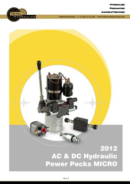
2012<br />
AC & DC Hydraulic<br />
Power Packs MICRO<br />
Micra 1
Hydrauliek<br />
Pneumatiek<br />
Aandrijftechniek<br />
HEERHUGOWAARD . T: +31 (0)72 57 66 700 . WWW.TOTALHYDRAULICS<strong>BV</strong>.COM<br />
sales@hydronit.com · +39 0362 1841 210<br />
POWER PACKS MICRO series ordering code<br />
www.hydronit.com<br />
PPM2012/1-01<br />
Micro 2
Hydrauliek<br />
Pneumatiek<br />
Aandrijftechniek<br />
HEERHUGOWAARD . T: +31 (0)72 57 66 700 . WWW.TOTALHYDRAULICS<strong>BV</strong>.COM<br />
sales@hydronit.com · +39 0362 1841 210<br />
QUICK SELECTION GUIDE<br />
AC & DC electric motors<br />
Section A<br />
DC motors<br />
0,15 12DC_T 12VDC motor - 150W - Ø 80 + thermal switch<br />
0,15 24DC_T 24VDC motor - 150W - Ø 80 + thermal switch<br />
0,5 12DC 12VDC motor - 500W - Ø 80<br />
0,5 24DC 24VDC motor - 500W - Ø 80<br />
0,5 12DC_T 12VDC motor - 500W - Ø 80 + thermal switch<br />
0,5 24DC_T 24VDC motor - 500W - Ø 80 + thermal switch<br />
0,8 12DC 12VDC motor - 800W - Ø 80<br />
0,8 24DC 24VDC motor - 800W - Ø 80<br />
0,8 12DC_T 12VDC motor - 800W - Ø 80 + thermal switch<br />
0,8 24DC_T 24VDC motor - 800W - Ø 80 + thermal switch<br />
1,6 12DC_T 12VDC motor - 1600W - Ø 114 + thermal switch<br />
2,1 12DC_T 12VDC motor - 2100W - Ø 114 + thermal switch<br />
2,2 24DC_T 24VDC motor - 2200W - Ø 114 + thermal switch<br />
AC motors: three-phase 4 poles (~1450 rpm at 50Hz)<br />
N037AC341S3 integral motor 0,37kW 3-ph 4-pole 220/380V 50/60Hz frame 71<br />
N055AC341S3 integral motor 0,55kW 3-ph 4-pole 220/380V 50/60Hz frame 71<br />
N075AC341S3 integral motor 0,75kW 3-ph 4-pole 220/380V 50/60Hz frame 71<br />
AC motors: single-phase 4 poles (~1450 rpm at 50Hz)<br />
N037ACS41S3 integral motor 0,37kW 1-ph 4-pole 220V 50Hz frame 71<br />
N055ACS41S3 integral motor 0,55kW 1-ph 4-pole 220V 50Hz frame 71<br />
2 pole and special execution motors (High starting torque, high IP, with thermal protector,... available on request<br />
No motor: B14 Flange + coupling kit<br />
NB14 63 mounting kit for B14 motors frame 63<br />
NB14 71 mounting kit for B14 motors frame 71<br />
Electric motors options<br />
DC motor options<br />
S150 12DC 80<br />
S150 24DC 80<br />
S150 12DC 112<br />
S150 24DC 112<br />
starting relay 12VDC 150A with mounting kit for Ø 80 motors<br />
starting relay 24VDC 150A with mounting kit for Ø 80 motors<br />
starting relay 12VDC 150A with mounting kit for Ø 114 motors<br />
starting relay 24VDC 150A with mounting kit for Ø 114 motors<br />
www.hydronit.com<br />
PPM2012/1-02<br />
Micra 3
Hydrauliek<br />
Pneumatiek<br />
Aandrijftechniek<br />
HEERHUGOWAARD . T: +31 (0)72 57 66 700 . WWW.TOTALHYDRAULICS<strong>BV</strong>.COM<br />
sales@hydronit.com · +39 0362 1841 210<br />
QUICK SELECTION GUIDE<br />
Micro central manifold<br />
International execution (1/4" BSP exit ports)<br />
Section B<br />
MB<br />
MR<br />
M4<br />
Micro PPM B type body with 4 lateral cavities<br />
Micro PPM R type body for reversible circuits<br />
Micro PPM 4-way type body for 4 way cartridge valves<br />
USA execution (SAE 06 exit ports)<br />
MBUS<br />
MRUS<br />
M4US<br />
Micro PPM B type body with 4 lateral cavities US execution<br />
Micro PPM R type body for reversible circuits US execution<br />
Micro PPM 4-way type body for 4 way cartridge valves US execution<br />
Gear Pumps<br />
Standard gear pumps<br />
Section C<br />
GM0,1<br />
KM0,2<br />
KM0,4<br />
KM0,6<br />
KM0,9<br />
KM1,3<br />
KM1,5<br />
KM1,9<br />
gear pump group 0 – 0,19 cc/rev<br />
gear pump group 0 – 0,26 cc/rev<br />
gear pump group 0 – 0,38 cc/rev<br />
gear pump group 0 – 0,64 cc/rev<br />
gear pump group 0 – 0,88 cc/rev<br />
gear pump group 0 – 1,25 cc/rev<br />
gear pump group 0 – 1,54 cc/rev<br />
gear pump group 0 – 1,9 cc/rev<br />
Bi-directional gear pumps<br />
RM0,1<br />
RM0,2<br />
RM0,4<br />
RM0,6<br />
RM0,9<br />
RM1,3<br />
RM1,5<br />
reversible gear pump group 0 - 0,19 cc/rev<br />
Reversible gear pump group 0 - 0,26 cc/rev<br />
reversible gear pump - 0,38cc/rev<br />
reversible gear pump - 0,63 cc/rev<br />
reversible gear pump - 0,88cc/rev<br />
reversible gear pump - 1,25cc/rev<br />
reversible gear pump - 1,5cc/rev<br />
Integral components: Cavity 0<br />
Section D<br />
Components in central manifold cavity 0<br />
JM<br />
ML<br />
check valve ball type 5/8-18 UNF<br />
plug 5/8-18UNF basic<br />
Integral components: Cavity 1<br />
Components in central manifold cavity 1<br />
DM_60<br />
DM_280<br />
XM<br />
relief valve M14 - 10÷60 bar - socket screw adjustment<br />
relief valve M14 - 35÷280 bar - socket screw adjustment<br />
plug for relief valve cavity M14<br />
www.hydronit.com<br />
PPM2012/1-03<br />
Micro 4
Hydrauliek<br />
Pneumatiek<br />
Aandrijftechniek<br />
HEERHUGOWAARD . T: +31 (0)72 57 66 700 . WWW.TOTALHYDRAULICS<strong>BV</strong>.COM<br />
sales@hydronit.com · +39 0362 1841 210<br />
QUICK SELECTION GUIDE<br />
Integral components: Cavity 2<br />
Components in central manifold cavity 2<br />
X<br />
A<br />
B<br />
C<br />
D<br />
E<br />
EM<br />
Z<br />
S<br />
T12DC<br />
T24DC<br />
U<br />
G<br />
H<br />
N<br />
P<br />
L<br />
J<br />
4VA11C<br />
4VA2<br />
4VB2<br />
4VC2<br />
4VE2<br />
JP<br />
MG<br />
open cavity – no valve<br />
NC solenoid 2/2 way 3/4-16UNF poppet valve<br />
NC solenoid 2/2 way 3/4-16UNF poppet valve with emergency<br />
NO solenoid 2/2 way 3/4-16UNF poppet valve with emergency<br />
NC solenoid 2/2 way 3/4-16UNF double poppet valve with emergency<br />
lever operated 2/2 way valve without micro-switch<br />
lever operated 2/2 way valve with micro-switch<br />
2 way emergency button valve<br />
flow control valve 3/4-16UNF with screw<br />
proportional flow control valve poppet type 15l/min 315 bar + coil 12VDC ED100%<br />
proportional flow control valve poppet type 15l/min 315 bar + coil 24VDC ED100%<br />
hand pump 3/4-16UNF 2 cc/stroke + suction/return line pipe 1/4”BSP 370mm<br />
closed plug 3/4-16UNF<br />
plug 3/4-16UNF with 1/4”BSPP exit port<br />
plug 3/4-16UNF open passage with 1/4”BSPP exit port<br />
plug 3/4-16UNF passing through 1/4”BSPP<br />
plug 3/4-16UNF basic<br />
check valve ball type 3/4-16UNF<br />
4/2 way solenoid directional valve, closed center transient (only for M4 manifolds)<br />
4/3 way solenoid directional valve, center P to T (only for M4 manifolds)<br />
4/3 way solenoid directional valve, closed center (only for M4 manifolds)<br />
4/3 way solenoid directional valve, H center (only for M4 manifolds)<br />
4/3 way solenoid directional valve, center A-B to T (only for M4 manifolds)<br />
check valve poppet type 5/8-18 UNF (only for MR central manifolds)<br />
Closed plug 5/8-18UNF (only for MR central manifolds)<br />
Cavity 2 option<br />
V-CSB<br />
handwheel for CSB/CSU<br />
EM9001C pressure gauge shut-off valve 90° F-F + nipples M 1/4” BSPP – M 1/4” BSPP<br />
EMIL01C pressure gauge shut-off valve F-F + nipples M 1/4” BSPP – M 1/4” BSPP<br />
F401**<br />
pressure switch 1/4” BSPP where ** = max setting pressure (050-100-200-400 bar)<br />
MIR63**EM pressure gauge Ø63 where ** = max press. (60-160-250-315 bar) + shut-off valve 90°<br />
Cavity 2 valve coil<br />
12DC_M130 Coil 12V DC 18W ED75% for MSV30-31 + Electric connector DIN 43650-A<br />
24DC_M130 Coil 24V DC 18W ED75% for MSV30-31 + Electric connector DIN 43650-A<br />
24RAC_M130 Coil 24V DC 18W ED75% for MSV30-31 + El. connector with rectifier 12-24V<br />
115_50AC_M130 Coil 115V/50Hz AC 28VA ED75% only for MSV30 + El. connector DIN 43650-A<br />
230_50AC_M130 Coil 230V/50Hz AC 28VA ED75% only for MSV30 + El. connector DIN 43650-A<br />
110RAC_M130 Coil 110V RAC 18W ED75% for MSV30-31 + El. connector with rectifier 115 V<br />
220RAC_M130 Coil 220V RAC 18W ED75% for MSV30-31 + El. connector with rectifier 230 V<br />
www.hydronit.com<br />
PPM2012/1-04<br />
Micra 5
Hydrauliek<br />
Pneumatiek<br />
Aandrijftechniek<br />
HEERHUGOWAARD . T: +31 (0)72 57 66 700 . WWW.TOTALHYDRAULICS<strong>BV</strong>.COM<br />
sales@hydronit.com · +39 0362 1841 210<br />
QUICK SELECTION GUIDE<br />
Cavity 2 valve coil<br />
12DC_M140 Coil 12V DC 22W ED100% for MSV-MDV + Electric connector DIN 43650-A<br />
24DC_M140 Coil 24V DC 22W ED100% for MSV-MDV + Electric connector DIN 43650-A<br />
24RAC_M140 Coil 24V DC 22W ED100% for MSV-MDV + El. connector with rectifier 12-24 V<br />
110RAC_M140 Coil 110V RAC 22W ED100% for MSV-MDV + El. connector with rectifier 115 V<br />
220RAC_M140 Coil 220V RAC 22W ED100% for MSV-MDV + El. connector with rectifier 230 V<br />
12DC_M630 coil 12V DC ED100% for cartridge valves + Electric connector DIN 43650-A<br />
24DC_M630 coil 24V DC ED100% for cartridge valves + Electric connector DIN 43650-A<br />
24AC_M631 coil 24V AC ED100% for cartridge valves + integrated rectifier + Electric connector<br />
115AC_M631 coil 115V AC ED100% for cartridge valves + integrated rectifier + Electric connector<br />
230AC_M631 coil 230V AC ED100% for cartridge valves + integrated rectifier + Electric connector<br />
Integral components: Cavity 3<br />
Components in central manifold cavity 3<br />
F02<br />
F03<br />
F04<br />
F05<br />
F06<br />
F07<br />
F09<br />
F11<br />
F13<br />
F15<br />
R2<br />
R3<br />
R4<br />
R5<br />
R6<br />
R7<br />
S<br />
Z<br />
AR<br />
BR<br />
CR<br />
D<br />
J<br />
G<br />
H<br />
N<br />
P<br />
L<br />
P**12DC<br />
P**24DC<br />
V**<br />
JP<br />
MG<br />
fixed pressure compensated flow control valve 3/4-16UNF hole 0,8mm<br />
fixed pressure compensated flow control valve 3/4-16UNF hole 1mm<br />
fixed pressure compensated flow control valve 3/4-16UNF hole 1,25mm<br />
fixed pressure compensated flow control valve 3/4-16UNF hole 1,5mm<br />
fixed pressure compensated flow control valve 3/4-16UNF hole 1,75mm<br />
fixed pressure compensated flow control valve 3/4-16UNF hole 2mm<br />
fixed pressure compensated flow control valve 3/4-16UNF hole 2,5mm<br />
fixed pressure compensated flow control valve 3/4-16UNF hole 3mm<br />
fixed pressure compensated flow control valve 3/4-16UNF hole 3,5mm<br />
fixed pressure compensated flow control valve 3/4-16UNF hole 4mm<br />
compensated flow control valve 3/4-16UNF with screw 1 ÷ 2,2 l/min<br />
compensated flow control valve 3/4-16UNF with screw 1,6 ÷ 4 l/min<br />
compensated flow control valve 3/4-16UNF with screw 2,5 ÷ 5 l/min<br />
compensated flow control valve 3/4-16UNF with screw 3÷ 7 l/min<br />
compensated flow control valve 3/4-16UNF with screw 4,9 ÷ 10,8 l/min<br />
compensated flow control valve 3/4-16UNF with screw 8 ÷ 18,5 l/min<br />
flow control valve 3/4-16UNF with screw<br />
2 way emergency button valve<br />
NC solenoid 2/2 way 3/4-16UNF poppet valve, reversible flow<br />
NC solenoid 2/2 way 3/4-16UNF poppet valve with emergency, reversible flow<br />
NO solenoid 2/2 way 3/4-16UNF poppet valve with emergency, reversible flow<br />
NC solenoid 2/2 way 3/4-16UNF double poppet valve with emergency<br />
check valve ball type 3/4-16UNF<br />
closed plug 3/4-16UNF<br />
plug 3/4-16UNF with 1/4”BSPP exit port<br />
plug 3/4-16UNF open passage with 1/4”BSPP exit port<br />
plug 3/4-16UNF passing through 1/4”BSPP<br />
plug 3/4-16UNF basic<br />
proportional relief valve 3/4-16UNF 12VDC where ** = max pressure (60-210 bar)<br />
proportional relief valve 3/4-16UNF 24VDC where ** = max pressure (60-210 bar)<br />
relief valve 3/4-16UNF where ** = max pressure (110-250-350 bar) - socket screw<br />
check valve poppet type 5/8-18 UNF (only for MR central manifolds)<br />
Closed plug 5/8-18UNF (only for MR central manifolds)<br />
www.hydronit.com<br />
PPM2012/1-05<br />
Micro 6
Hydrauliek<br />
Pneumatiek<br />
Aandrijftechniek<br />
HEERHUGOWAARD . T: +31 (0)72 57 66 700 . WWW.TOTALHYDRAULICS<strong>BV</strong>.COM<br />
sales@hydronit.com · +39 0362 1841 210<br />
QUICK SELECTION GUIDE<br />
Cavity 3 option<br />
V-CSB<br />
handwheel for CSB/CSU<br />
2 handwheel M8 for VMDC35/VMDC20/VCF6 valves<br />
EM9001C pressure gauge shut-off valve 90° F-F + nipples M 1/4” BSPP – M 1/4” BSPP<br />
EMIL01C pressure gauge shut-off valve F-F + nipples M 1/4” BSPP – M 1/4” BSPP<br />
F401**<br />
pressure switch 1/4” BSPP where ** = max setting pressure (050-100-200-400 bar)<br />
MIR63**EM pressure gauge Ø63 where ** = max press. (60-160-250-315 bar) + shut-off valve 90°<br />
Cavity 3 valve coil voltage<br />
12DC_M130 Coil 12V DC 18W ED75% for MSV30-31 + Electric connector DIN 43650-A<br />
24DC_M130 Coil 24V DC 18W ED75% for MSV30-31 + Electric connector DIN 43650-A<br />
24RAC_M130 Coil 24V DC 18W ED75% for MSV30-31 + El. connector with rectifier 12-24 V<br />
115_50AC_M130 Coil 115V/50Hz AC 28VA ED75% only for MSV30 + Electric connector DIN 43650-A<br />
230_50AC_M130 Coil 230V/50Hz AC 28VA ED75% only for MSV30 + Electric connector DIN 43650-A<br />
110RAC_M130 Coil 110V RAC 18W ED75% for MSV30-31 + El. connector with rectifier 115 V<br />
220RAC_M130 Coil 220V RAC 18W ED75% for MSV30-31 + El. connector with rectifier 230 V<br />
12DC_M140 Coil 12V DC 22W ED100% for MSV-MDV + Electric connector DIN 43650-A<br />
24DC_M140 Coil 24V DC 22W ED100% for MSV-MDV + Electric connector DIN 43650-A<br />
24RAC_M140 Coil 24V DC 22W ED100% for MSV-MDV + El. connector with rectifier 12-24 V<br />
110RAC_M140 Coil 110V RAC 22W ED100% for MSV-MDV + El. connector with rectifier 115 V<br />
220RAC_M140 Coil 220V RAC 22W ED100% for MSV-MDV + El. connector with rectifier 230 V<br />
Integral components: Cavity 4<br />
Component in central manifold cavity 4 (only for MR central manifold)<br />
DM_60<br />
DM_280<br />
XM<br />
relief valve M14 - 10÷60 bar - socket screw adjustment<br />
relief valve M14 - 35÷280 bar - socket screw adjustment<br />
plug for relief valve cavity M14<br />
Flow restrictor in central manifold cavity 5<br />
Flow restrictor in central manifold cavity 5<br />
PLUGTCE01<br />
PP01370<br />
1/4” BSPP plug with copper washer<br />
suction/return line pipe 1/4”BSP 370mm<br />
RETURN-KIT 1/4” BSP holder for SF12 + flexible plastic pipe 12 mm for return line / price per meter<br />
C34200001 return line tank immersed filter<br />
1(01) fixed pressure compensated flow control valve 1/4"BSP 1l/min<br />
2(01) fixed pressure compensated flow control valve 1/4"BSP 2l/min<br />
3(01) fixed pressure compensated flow control valve 1/4"BSP 3l/min<br />
4(01) fixed pressure compensated flow control valve 1/4"BSP 4l/min<br />
5(01) fixed pressure compensated flow control valve 1/4"BSP 5l/min<br />
6(01) fixed pressure compensated flow control valve 1/4"BSP 6l/min<br />
8(01) fixed pressure compensated flow control valve 1/4"BSP 8l/min<br />
10(01) fixed pressure compensated flow control valve 1/4"BSP 10l/min<br />
12(01) fixed pressure compensated flow control valve 1/4"BSP 12l/min<br />
15(01) fixed pressure compensated flow control valve 1/4"BSP 15l/min<br />
www.hydronit.com<br />
PPM2012/1-06<br />
Micra 7
Hydrauliek<br />
Pneumatiek<br />
Aandrijftechniek<br />
HEERHUGOWAARD . T: +31 (0)72 57 66 700 . WWW.TOTALHYDRAULICS<strong>BV</strong>.COM<br />
sales@hydronit.com · +39 0362 1841 210<br />
QUICK SELECTION GUIDE<br />
Flow restrictor in central manifold cavity 7<br />
Flow restrictor in central manifold cavity 7<br />
0(04) closed plug Ø 12,7<br />
1(04) fixed pressure compensated flow control valve Ø 12,7 with o-ring 1l/min<br />
2(04) fixed pressure compensated flow control valve Ø 12,7 with o-ring 2l/min<br />
3(04) fixed pressure compensated flow control valve Ø 12,7 with o-ring 3l/min<br />
4(04) fixed pressure compensated flow control valve Ø 12,7 with o-ring 4l/min<br />
5(04) fixed pressure compensated flow control valve Ø 12,7 with o-ring 5l/min<br />
6(04) fixed pressure compensated flow control valve Ø 12,7 with o-ring 6l/min<br />
8(04) fixed pressure compensated flow control valve Ø 12,7 with o-ring 8l/min<br />
10(04) fixed pressure compensated flow control valve Ø 12,7with o-ring 10l/min<br />
12(04) fixed pressure compensated flow control valve Ø 12,7 with o-ring 12l/min<br />
15(04) fixed pressure compensated flow control valve Ø 12,7 with o-ring 15l/min<br />
PIL5818 pilot Ø 12,7 for PO check valve 5/8-18UNF VUC10C<br />
PIL5818DIF pilot Ø 12,7 for PO check valve 5/8-18UNF VUC10C + valve for differential cylinders<br />
Flow restrictor in central manifold cavity 8<br />
Flow restrictor in central manifold cavity 8<br />
PLUGTCE01<br />
PP01370<br />
1/4” BSPP plug with copper washer<br />
suction/return line pipe 1/4”BSP 370mm<br />
RETURN-KIT 1/4” BSP holder for SF12 + flexible plastic pipe 12 mm for return line / price per meter<br />
C34200001 return line tank immersed filter<br />
1(01) fixed pressure compensated flow control valve 1/4"BSP 1l/min<br />
2(01) fixed pressure compensated flow control valve 1/4"BSP 2l/min<br />
3(01) fixed pressure compensated flow control valve 1/4"BSP 3l/min<br />
4(01) fixed pressure compensated flow control valve 1/4"BSP 4l/min<br />
5(01) fixed pressure compensated flow control valve 1/4"BSP 5l/min<br />
6(01) fixed pressure compensated flow control valve 1/4"BSP 6l/min<br />
8(01) fixed pressure compensated flow control valve 1/4"BSP 8l/min<br />
10(01) fixed pressure compensated flow control valve 1/4"BSP 10l/min<br />
12(01) fixed pressure compensated flow control valve 1/4"BSP 12l/min<br />
15(01) fixed pressure compensated flow control valve 1/4"BSP 15l/min<br />
www.hydronit.com<br />
PPM2012/1-07<br />
Micro 8
Hydrauliek<br />
Pneumatiek<br />
Aandrijftechniek<br />
HEERHUGOWAARD . T: +31 (0)72 57 66 700 . WWW.TOTALHYDRAULICS<strong>BV</strong>.COM<br />
sales@hydronit.com · +39 0362 1841 210<br />
QUICK SELECTION GUIDE<br />
Tanks<br />
Section E<br />
Steel tanks<br />
0,7F 0,7l cylindrical steel horizontal mounting tank + 3/8"BSPP std filler & breather plug<br />
0,7FV<br />
0,7l cylindrical steel vertical mounting tank + 3/8"BSPP std filler & breather plug<br />
1,2F 1,2l cylindrical steel horizontal mounting tank + 3/8"BSPP std filler & breather plug<br />
1,2FV<br />
1,2l cylindrical steel vertical mounting tank + 3/8"BSPP std filler & breather plug<br />
1,7H 1,7l cylindrical steel horizontal mounting tank + 3/8"BSPP std filler & breather plug<br />
1,7HV<br />
1,7l cylindrical steel vertical mounting tank + 3/8"BSPP std filler & breather plug<br />
2,4H 2,4l cylindrical steel horizontal mounting tank + 3/8"BSPP std filler & breather plug<br />
2,4HV<br />
2,4l cylindrical steel vertical mounting tank + 3/8"BSPP std filler & breather plug<br />
F80000012 steel tank adapter for PPM - to be welded on custom made tanks<br />
Plastic tanks<br />
0,4R 0,4l plastic horizontal mounting tank + 1/4"BSPP std filler & breather plug<br />
0,4RV<br />
0,4l plastic vertical mounting tank + 1/4"BSPP std filler & breather plug<br />
0,7R<br />
0,7l plastic horizontal mounting tank + 1/4"BSPP std filler & breather plug<br />
0,7RV<br />
0,7l plastic vertical mounting tank + 1/4"BSPP std filler & breather plug<br />
1,2R 1,2l plastic horizontal mounting tank + 1/4"BSPP std filler & breather plug<br />
1,2RV<br />
1,2l plastic vertical mounting tank + 1/4"BSPP std filler & breather plug<br />
Accessories<br />
Section F<br />
Accessories<br />
E60543003<br />
MIR63**<br />
EM9001C<br />
EMIL01C<br />
F16000001<br />
F401**<br />
P0201<br />
P0202<br />
VPC00<br />
BFCSAE0801<br />
BFCSAE0802<br />
foot mounting support (45mm height)<br />
pressure gauge Ø63 where ** = max press. (60-160-250-315 bar)<br />
pressure gauge shut-off valve 90° F-F + nipples M 1/4” BSPP – M 1/4” BSPP<br />
pressure gauge shut-off valve F-F + nipples M 1/4” BSPP – M 1/4” BSPP<br />
plastic Ø112-114 DC motor protection cover<br />
pressure switch 1/4” BSPP where ** = max setting pressure (050-100-200-400 bar)<br />
remote up/down control with 3m flying cable for single/double acting cylinder<br />
Remote 4 buttons control with 3m flying cable for 2 double acting cylinders<br />
electronic PWM driver for proportional valves 12/24VDC<br />
in-line manifolds for 3/4-16UNF valves 1/4” BSPP ports<br />
in-line manifolds for 3/4-16UNF valves 3/8” BSPP ports<br />
External manifolds<br />
External manifolds<br />
M60403004<br />
M60403005<br />
M60403010(US)<br />
M60413002(US)<br />
M60413001(US)<br />
M60413003(US)<br />
M50403007<br />
PM09M<br />
23mm spacer subplate<br />
90° rotation manifold<br />
NG3 MICRO parallel block - 1/4” BSPP lateral ports (opt. US execution with SAE ports)<br />
NG3 MICRO manifold with piloted check valve on A (opt. US execution with SAE ports)<br />
NG3 MICRO manifold with piloted check valve on A & B (opt. US exec. with SAE ports)<br />
NG3 MICRO manifold with piloted check valve on B (opt. US execution with SAE ports)<br />
PPM to SD01 stackable valves converter manifold<br />
hand pump 8,8 cc/stroke modular manifold<br />
www.hydronit.com<br />
PPM2012/1-08<br />
Micra 9
Hydrauliek<br />
Pneumatiek<br />
Aandrijftechniek<br />
HEERHUGOWAARD . T: +31 (0)72 57 66 700 . WWW.TOTALHYDRAULICS<strong>BV</strong>.COM<br />
sales@hydronit.com · +39 0362 1841 210<br />
QUICK SELECTION GUIDE<br />
External valves<br />
External valves<br />
Section G<br />
SD00A11C<br />
SD00A2<br />
NG3 MICRO solenoid directional valve 4 way, 2 positions<br />
NG3 MICRO solenoid directional valve 4 way, 3 pos. center P to T<br />
SD00B2 NG3 MICRO solenoid directional valve 4 way, 3 pos. closed center<br />
SD00C2 NG3 MICRO solenoid directional valve 4 way, 3 pos. H center<br />
SD00E2 NG3 MICRO solenoid directional valve 4 way, 3 pos. center A-B to T<br />
SD01A11C Stackable solenoid directional valve 4 way, 2 positions<br />
SD01A2 Stackable solenoid directional valve 4 way, 3 pos. center P to T<br />
SD01B2 Stackable solenoid directional valve 4 way, 3 pos. closed center<br />
SD01C2 Stackable solenoid directional valve 4 way, 3 pos. H center<br />
SD01E2 Stackable solenoid directional valve 4 way, 3 pos. center A-B to T<br />
SD01A11CC Stackable solenoid directional valve 4 way, 2 positions, stack top closed<br />
SD01A2C Stackable solenoid directional valve 4 way, 3 pos. center P to T, stack top closed<br />
SD01B2C Stackable solenoid directional valve 4 way, 3 pos. closed center, stack top closed<br />
SD01C2C Stackable solenoid directional valve 4 way, 3 pos. H center, stack top closed<br />
SD01E2C Stackable solenoid directional valve 4 way, 3 pos. center A-B to T, stack top closed<br />
External SD00 valves coils<br />
12DC_M100 coil 12V DC 16W ED100% + Electric connector DIN 43650-A<br />
24DC_M100 coil 24V DC 16W ED100% + Electric connector DIN 43650-A<br />
External SD01 valves coils<br />
12DC_M120 coil 12V DC 22W ED100% + Electric connector DIN 43650-A<br />
24DC_M120 coil 24V DC 22W ED100% + Electric connector DIN 43650-A<br />
24RAC_M120 coil 24V DC 22W ED100% + El. conn. with rectifier 12-24 V black pg11<br />
220RAC_M120 coil 220V RAC 26W ED100% + El. conn. with rectifier 230 V black pg11<br />
www.hydronit.com<br />
PPM2012/1-09<br />
Micro 10
Hydrauliek<br />
Pneumatiek<br />
Aandrijftechniek<br />
HEERHUGOWAARD . T: +31 (0)72 57 66 700 . WWW.TOTALHYDRAULICS<strong>BV</strong>.COM<br />
sales@hydronit.com · +39 0362 1841 210<br />
SECTION A<br />
AC & DC ELECTRIC MOTORS<br />
Integral AC motors: the engineered solution for compact and optimised power units from 0,25 to 1,8 kW,<br />
single or three phase. The AC motors are directly flanged on the central manifold for extra compactness.<br />
A single coupling can suit all powers. We suggest to adopt these advanced motors because of their<br />
peculiar advantages over standard B14 IEC AC motors and because they are designed specifically for use<br />
on our micro power packs, offering an higher power density and high starting torque (in HT models) than<br />
market standard motors. These motors are intendend for intermittent use (S3 40%), which is the case for<br />
most micro-power packs applications. They can be used in emergency situations continuously at a reduced<br />
rated power (about 30% less than S3 nominal power).<br />
Single phase motors should not run in any case without load for long time to avoid overheating.<br />
B14 IEC standard AC motors: the standard solution easily<br />
available on every market from 0,12 to 0,55 kW, single or three<br />
phase. These motors are normally procured by the customer<br />
itself. Hydronit provides adaptor flanges and double piece<br />
coupling for frame size: 63 and 71.<br />
Frame 80 DC motors: with or without thermal<br />
protector and running time up to 6 min. Power<br />
from 0,15kW up to 0,8kW 12 or 24VDC.<br />
The permanent magnet construction allow their<br />
use in bidirectional units.<br />
Frame 114 DC motors: power up to 2,2kW<br />
24VDC for high performances. All motors have<br />
thermal protector switch as standard.<br />
Are AC motors compliant with the European Union Minimum Energy Performance Standards?<br />
Hydronit AC motors are manufactured in Italy with the best technologies nowadays available and are specifically designed for mini<br />
power packs duties, which are typically intermittent. Hydronit motors have an higher power density, lower weight, lower cost,<br />
comparing to standard IE2 motors on the market. Due to the specific field of applications, Hydronit motors are not included in the<br />
requirements of the above mentioned normative, since they are specially and solely manufactured for mini power packs intermittent<br />
duties. For continuous duty applications IE2 motors (IEC 60034-30) must be applied. Ask our sales office.<br />
Are there special requirements to mount IEC B14 motors?<br />
No special toolings are required. Please strictly follow motor side coupling mounting dimension tolerance as per the relevant drawings.<br />
Failing in doing so may cause malfunctioning of the power pack and even the break of the coupling and pump.<br />
Can I start single phase AC motors under load?<br />
Single phase motors have a reduced starting torque due to their intrinsecal design. Normally this ranges around 30-40% of the nominal<br />
torque at full power output. When designing circuits where a single phase motor must start under load, a proper dimensioning must be<br />
done and test on field must be preliminary performed. High starting torque «HT» motors are available. Ask our technical office.<br />
How do I dimension a DC motor?<br />
These motors are normally for intermittent duty. It is important to know required flow in l/min, working pressure in bar and the duty<br />
charge. Then following A040 table instructions a proper motor/pump combination can be selected.<br />
www.hydronit.com<br />
PPM2012/1-A000<br />
Micra 11
Hydrauliek<br />
Pneumatiek<br />
Aandrijftechniek<br />
HEERHUGOWAARD . T: +31 (0)72 57 66 700 . WWW.TOTALHYDRAULICS<strong>BV</strong>.COM<br />
sales@hydronit.com · +39 0362 1841 210<br />
SECTION A<br />
INTEGRAL DC MOTORS Ø 80<br />
Starting switch option<br />
25,5<br />
10,5<br />
Ø 7<br />
Permanent magnets<br />
Protection degree: IP54<br />
Insulation class: F<br />
Code<br />
Thermal protection option<br />
2,5 L<br />
19<br />
Weight 500W/800W: 2,6 kg (without starter)<br />
Weight 150W: 2 kg (without starter)<br />
89,5<br />
Rotation<br />
Description<br />
PPC assembly<br />
code<br />
Spare part code<br />
Nominal<br />
duty cycle<br />
Nominal<br />
speed<br />
Nominal<br />
current<br />
L<br />
150W 12V DC + thermal protector 0,15 12DC/T M46C1ST01<br />
150W 24V DC + thermal protector 0,15 24DC/T M46C2ST01<br />
500W 12V DC motor 0,5 12DC M46C1S005<br />
500W 24V DC motor 0,5 24DC M46C2S005<br />
500W 12V DC + thermal protector 0,5 12DC/T M46C1ST05<br />
500W 24V DC + thermal protector 0,5 24DC/T M46C2ST05<br />
800W 12V DC motor 0,8 12DC M46C1S008<br />
800W 24V DC motor 0,8 24DC M46C2S008<br />
800W 12V DC + thermal protector 0,8 12DC/T M46C1ST08<br />
800W 24V DC + thermal protector 0,8 24DC/T M46C2ST08<br />
Options & coupling<br />
Description PPC assembly code Spare part code<br />
12V DC 150 Amp start switch + mounting kit S150 12DC 80 M47SC0001 + M47SK0801<br />
24V DC 150 Amp start switch + mounting kit S150 24DC 80 M47SC0002 + M47SK0801<br />
Remote wired control with 2 buttons and 3m cable<br />
Remote wired control with 4 buttons and 3m cable<br />
Coupling for Ø 80 DC motors<br />
S2:25 min<br />
S3: 50% ED<br />
S2: 25 min<br />
S3: 50% ED<br />
S2: 5 min<br />
S3: 17% ED<br />
S2: 5 min<br />
S3: 17% ED<br />
S2: 5 min<br />
S3: 17% ED<br />
S2: 5 min<br />
S3: 17% ED<br />
S2: 4 min<br />
S3: 10% ED<br />
S2: 4 min<br />
S3: 10% ED<br />
S2: 4 min<br />
S3: 10% ED<br />
S2: 4 min<br />
S3: 10% ED<br />
P0201 (single acting)<br />
P0202 (double acting)<br />
E36200003<br />
1400 rpm 30 A 108 mm<br />
1400 rpm 15 A 108 mm<br />
1700 rpm 90 A 139 mm<br />
2300 rpm 45 A 139 mm<br />
1700 rpm 90 A 139 mm<br />
2300 rpm 45 A 139 mm<br />
2100 rpm 150 A 139 mm<br />
2400 rpm 75 A 139 mm<br />
2100 rpm 150 A 139 mm<br />
2400 rpm 75 A 139 mm<br />
Notes: the starting<br />
switch mounting kit is<br />
provided when<br />
specifying the /S150 as<br />
motor option in PPM<br />
assembly code.<br />
When ordering spare<br />
starting switches, it must<br />
be ordered separately<br />
(code: M47SK0801).<br />
E36200003<br />
28,5<br />
18<br />
7<br />
6,4<br />
Weight: 0,063 kg<br />
The coupling is already<br />
included when<br />
specifying the motor in<br />
PPM assembly code.<br />
It is to be indicated only<br />
when ordering PPM with<br />
no motor but with<br />
coupling.<br />
www.hydronit.com<br />
PPM2012/1-A010<br />
Micro 12
Hydrauliek<br />
Pneumatiek<br />
Aandrijftechniek<br />
HEERHUGOWAARD . T: +31 (0)72 57 66 700 . WWW.TOTALHYDRAULICS<strong>BV</strong>.COM<br />
sales@hydronit.com · +39 0362 1841 210<br />
SECTION A<br />
INTEGRAL DC MOTORS Ø 114<br />
Starting switch option<br />
12<br />
Compound wound<br />
Protection degree: IP54<br />
Insulation class: F<br />
Weight: 7,05 kg (without starter)<br />
162<br />
90±<br />
0.2<br />
Rotation<br />
Code<br />
5,7<br />
3,5<br />
Description<br />
PPC assembly<br />
code<br />
Spare part code<br />
Nominal<br />
duty cycle<br />
Nominal<br />
speed<br />
Nominal<br />
current<br />
1600W 12V DC + thermal protector 1,6 12DC/T M46C1ST16<br />
2100W 12V DC + thermal protector 2,1 12DC/T M46C1ST21<br />
2200W 24V DC + thermal protector 2,2 24DC/T M46C2ST22<br />
Options & coupling<br />
S2: 5 min<br />
S3: 10% ED<br />
S2: 4 min<br />
S3: 12% ED<br />
S2: 2.5 min<br />
S3: 10% ED<br />
2800 rpm 210 A<br />
2400 rpm 300 A<br />
2400 rpm 130 A<br />
Description PPC assembly code Spare part code<br />
12V DC 150 Amp start switch + mounting kit S150 12DC 112 M47SC0001 + M47SK1121<br />
24V DC 150 Amp start switch + mounting kit S150 24DC 112 M47SC0002 + M47SK1121<br />
Remote wired control with 2 buttons and 3m cable<br />
Remote wired control with 4 buttons and 3m cable<br />
DC motor plastic cover<br />
Coupling for Ø114 motors<br />
P0201 (single acting)<br />
P0202 (double acting)<br />
F16000001<br />
E36200002<br />
Notes: the starting switch mounting kit is provided when specifying the /S150 as motor option in PPM assembly code.<br />
When ordering spare starting switches, it must be ordered separately (code: M47SK1121).<br />
The coupling is already included when specifying the motor in PPM assembly code.<br />
It is to be indicated only when ordering PPM with no motor but with coupling.<br />
127<br />
Motor plastic cover F16000001<br />
Coupling E36200002<br />
7<br />
6,4<br />
37<br />
180<br />
Ø148<br />
Weight: 0,27 kg<br />
Weight: 0,041 kg<br />
www.hydronit.com<br />
PPM2012/1-A020<br />
Micra 13
Hydrauliek<br />
Pneumatiek<br />
Aandrijftechniek<br />
HEERHUGOWAARD . T: +31 (0)72 57 66 700 . WWW.TOTALHYDRAULICS<strong>BV</strong>.COM<br />
sales@hydronit.com · +39 0362 1841 210<br />
SECTION A<br />
DC MOTORS OPTIONS<br />
Remote control P0201<br />
for one single or double acting cylinder<br />
Weight: 0,58 kg<br />
Protection degree: IP65<br />
Remote control P0202<br />
for two double acting cylinders<br />
Weight: 0,60 kg<br />
Protection degree: IP65<br />
60<br />
60<br />
Spare part code<br />
P0201<br />
Spare part code<br />
P0202<br />
Electric connection schemes<br />
+<br />
-<br />
+<br />
-<br />
+ +<br />
- -<br />
+ -<br />
+ -<br />
Starting switch<br />
Single acting cylinder<br />
M<br />
Green<br />
Thermal switch<br />
Red<br />
Red<br />
MSV<br />
Black<br />
Remote control P0201<br />
White<br />
Black<br />
Starting switch<br />
+<br />
M<br />
+<br />
-<br />
+ -<br />
Starting switch<br />
Thermal switch<br />
Red<br />
Blue<br />
Brown (up)<br />
Green (down)<br />
+<br />
-<br />
Directional<br />
valve (a<br />
second<br />
directional<br />
valve for<br />
left/right<br />
movement can<br />
be attached)<br />
Double acting cylinder<br />
M<br />
Remote control P0201 (2 buttons)<br />
for one double acting cylinder<br />
or P0202 (4 buttons)<br />
for two double acting cylinders<br />
www.hydronit.com<br />
PPM2012/1-A030<br />
Micro 14
Hydrauliek<br />
Pneumatiek<br />
Aandrijftechniek<br />
HEERHUGOWAARD . T: +31 (0)72 57 66 700 . WWW.TOTALHYDRAULICS<strong>BV</strong>.COM<br />
sales@hydronit.com · +39 0362 1841 210<br />
SECTION A<br />
DC MOTORS CHOICE AND ELECTRIC CONNECTION SCHEMES<br />
DC motors choice<br />
Once required pressure and flow and available voltage (12 or 24V DC) are known, you can select the motor checking on<br />
each provided diagram if a pump displacement is available at the inter<strong>section</strong> of pressure and flow values. On the<br />
relevant “I” curve you obtain the absorbed current. When the inter<strong>section</strong> point is not exactly on a pump curve, choose the<br />
closer smaller pump.<br />
On the right hand diagram, from the current value, you can easily obtain the maximum allowed S2 (min) and S3 (%) values.<br />
S2 gives the allowable motor continuous running time in minutes, S3 gives the allowable running time in % of the<br />
total cycle.<br />
If obtained S2 and S3 values are not enough for required duty cycle, choose a higher power or heavier duty motor and repeat<br />
the calculation on the new motor curves.<br />
Example:<br />
For our application we have following data:<br />
flow = 4 l/min, max pressure = 180 bar, not clearly defined duty cycle.<br />
-We check on 1,6 Kw 12V DC motor diagram and see there is a pump available.<br />
3<br />
-We choose from curves 1,66 pump: a 1,66 cm /rev pump. On the corresponding “I” curve we read 195 A absorbed current.<br />
In these conditions on the S2 / S3 diagram we read that the DC motor can work for maximum 5 min (S2), that<br />
is 18% (S3) of the total cycle, i.e. after 5 min working, the motor should cool down for at least 23 min.<br />
-The total cycle time is calculated adding the working time and the idle time (17% working time plus 83% idle time),<br />
in this case 28 min. If this duty cycle is not adequate for our application, we must choose a higher power or higher duty DC<br />
motor and check the relevant diagram again.<br />
Q(l/ min)<br />
M46C1ST16<br />
I (A)<br />
20<br />
18<br />
4,3 3,8<br />
3,3<br />
2,8<br />
2,17<br />
1,66 1,27<br />
250<br />
S3<br />
16<br />
14<br />
0,89<br />
200<br />
12<br />
150<br />
10<br />
8<br />
100<br />
3,3<br />
6<br />
2,8<br />
2,17<br />
4<br />
1,66<br />
1,27<br />
50<br />
2<br />
0,89<br />
0<br />
0<br />
0 50 100 150 200 250 300<br />
P(bar)<br />
S2(min) 2 4 6 8 10 12<br />
S3(%) 4 8 12 16 20 24<br />
www.hydronit.com<br />
PPM2012/1-A040<br />
Micra 15
Hydrauliek<br />
Pneumatiek<br />
Aandrijftechniek<br />
HEERHUGOWAARD . T: +31 (0)72 57 66 700 . WWW.TOTALHYDRAULICS<strong>BV</strong>.COM<br />
sales@hydronit.com · +39 0362 1841 210<br />
SECTION A<br />
DC MOTORS Ø80 DIAGRAMS<br />
Q(l/ min)<br />
150W 12VDC<br />
M46C1S001<br />
I (A)<br />
3<br />
50<br />
45<br />
2,5<br />
2<br />
1,25<br />
1,25<br />
0,88<br />
0,64<br />
0,38<br />
0,26<br />
40<br />
35<br />
30<br />
1,5<br />
0,88<br />
25<br />
S3<br />
20<br />
1<br />
15<br />
S2<br />
0,5<br />
0,64<br />
0,38<br />
10<br />
5<br />
0,26<br />
0<br />
0<br />
0 20 40 60 80 100 120 140 160 180 200<br />
P(bar)<br />
S2(min)<br />
S3(%)<br />
24<br />
45<br />
28<br />
50<br />
32<br />
55<br />
36<br />
60<br />
40<br />
65<br />
44<br />
70<br />
Q(l/ min)<br />
150W 24VDC<br />
M46C2S001<br />
I (A)<br />
3<br />
25<br />
2,5<br />
0,64<br />
0,38<br />
20<br />
2<br />
1,25<br />
1,25<br />
0,88<br />
0,26<br />
15<br />
1,5<br />
S3<br />
10<br />
1<br />
0,88<br />
S2<br />
0,5<br />
0,64<br />
0,38<br />
5<br />
0,26<br />
0<br />
0<br />
0 20 40 60 80 100 120 140 160 180 200<br />
P(bar)<br />
S2(min)<br />
S3(%)<br />
24<br />
45<br />
28<br />
50<br />
32<br />
55<br />
36<br />
60<br />
40<br />
65<br />
44<br />
70<br />
Q (l/ min)<br />
500W 12VDC<br />
M46C1S005<br />
I (A)<br />
5<br />
100<br />
4,5<br />
4<br />
1,54<br />
1,54<br />
1,25<br />
0,88<br />
0,64<br />
0,38<br />
0,26<br />
90<br />
80<br />
3,5<br />
1,25<br />
70<br />
S2<br />
S3<br />
3<br />
60<br />
2,5<br />
50<br />
2<br />
0,88<br />
40<br />
1,5<br />
30<br />
0,64<br />
1<br />
20<br />
0,38<br />
0,5<br />
10<br />
0,26<br />
0<br />
0<br />
0 50 100 150 200 250 300<br />
P(bar)<br />
S2(min)<br />
S3(%)<br />
2 4 6 8 10 12<br />
10 14 18 22 26 30<br />
Tests made with rectified current supplied at nominal motor voltage (measured at the motor connection terminals) and oil ISO VG46 at 40°C<br />
www.hydronit.com<br />
PPM2012/1-A050<br />
Micro 16
Hydrauliek<br />
Pneumatiek<br />
Aandrijftechniek<br />
HEERHUGOWAARD . T: +31 (0)72 57 66 700 . WWW.TOTALHYDRAULICS<strong>BV</strong>.COM<br />
sales@hydronit.com · +39 0362 1841 210<br />
SECTION A<br />
DC MOTORS Ø80 DIAGRAMS<br />
Q(l/ min)<br />
500W 24VDC<br />
M46C2S005<br />
I (A)<br />
5<br />
50<br />
4,5<br />
4<br />
1,54<br />
1,25<br />
1,54<br />
0,88<br />
0,64<br />
0,38<br />
45<br />
40<br />
3,5<br />
3<br />
1,25<br />
0,26<br />
35<br />
30<br />
S2<br />
S3<br />
2,5<br />
25<br />
2<br />
20<br />
0,88<br />
1,5<br />
15<br />
0,64<br />
1<br />
10<br />
0,38<br />
0,5<br />
5<br />
0,26<br />
0<br />
0<br />
0 50 100 150 200 250 300<br />
P(bar)<br />
S2(min)<br />
S3(%)<br />
4 6 8 10 12 14<br />
12 16 20 24 28 32<br />
Q(l/ min)<br />
800W 12VDC<br />
M46C1S008<br />
I (A)<br />
7<br />
6<br />
5<br />
1,54<br />
1,25<br />
1,54<br />
1,25<br />
0,88<br />
0,64<br />
0,38<br />
0,26<br />
140<br />
120<br />
100<br />
S2<br />
S3<br />
4<br />
80<br />
3<br />
60<br />
2<br />
0,88<br />
0,64<br />
40<br />
1<br />
0,38<br />
20<br />
0,26<br />
0<br />
0<br />
0 50 100 150 200 250 300<br />
P(bar)<br />
S2(min)<br />
S3(%)<br />
2 4 6 8 10 12<br />
8 12 16 20 24 28<br />
Q(l/ min)<br />
800W 24VDC<br />
M46C2S008<br />
I (A)<br />
7<br />
120<br />
6<br />
5<br />
4<br />
3<br />
1,54<br />
1,25<br />
0,88<br />
1,54<br />
1,25<br />
0,88<br />
0,64<br />
0,38<br />
0,26<br />
100<br />
80<br />
60<br />
S3<br />
S2<br />
2<br />
1<br />
0,64<br />
0,38<br />
40<br />
20<br />
0,26<br />
0<br />
0<br />
0 50 100 150 200 250 300<br />
P(bar)<br />
S2(min)<br />
S3(%)<br />
2 4 6 8 10 12<br />
10 14 18 22 26 30<br />
Tests made with rectified current supplied at nominal motor voltage (measured at the motor connection terminals) and oil ISO VG46 at 35°C<br />
www.hydronit.com<br />
PPC2012/1-A060<br />
Micra 17
Hydrauliek<br />
Pneumatiek<br />
Aandrijftechniek<br />
HEERHUGOWAARD . T: +31 (0)72 57 66 700 . WWW.TOTALHYDRAULICS<strong>BV</strong>.COM<br />
sales@hydronit.com · +39 0362 1841 210<br />
SECTION A<br />
DC MOTORS Ø114 DIAGRAMS<br />
Q(l/ min)<br />
1600W 12VDC<br />
M46C1ST16<br />
I (A)<br />
9<br />
250<br />
8<br />
7<br />
6<br />
5<br />
1,54<br />
1,25<br />
0,88<br />
0,64<br />
1,54<br />
1,25<br />
0,88<br />
0,64<br />
0,38<br />
200<br />
150<br />
S3<br />
4<br />
3<br />
0,38<br />
0,26<br />
0,26<br />
100<br />
2<br />
50<br />
1<br />
0<br />
0<br />
0 50 100 150 200 250 300<br />
P(bar)<br />
S2(min) 2 6 10 14 18 22<br />
S3(%) 10 12 14 16 18 20<br />
Q(l/ min)<br />
2100W 12VDC<br />
M46C1ST21<br />
I (A)<br />
9<br />
300<br />
8<br />
7<br />
6<br />
5<br />
4<br />
3<br />
1,54<br />
1,25<br />
0,88<br />
0,64<br />
0,38<br />
0,26<br />
1,54<br />
1,25<br />
0,88<br />
0,64<br />
0,38<br />
0,26<br />
250<br />
200<br />
150<br />
100<br />
S2<br />
S3<br />
2<br />
1<br />
50<br />
0<br />
0<br />
0 50 100 150 200 250 300<br />
P(bar)<br />
S2(min) 10 14 18 22 26 30<br />
S3(%) 8 12 16 20 24 28<br />
Q(l/ min)<br />
2200W 24VDC<br />
M46C2ST22<br />
I (A)<br />
9<br />
140<br />
8<br />
7<br />
6<br />
5<br />
4<br />
1,54<br />
1,25<br />
0,88<br />
0,64<br />
0,38<br />
1,54<br />
1,25<br />
0,88<br />
0,64<br />
0,38<br />
0,26<br />
120<br />
100<br />
80<br />
60<br />
S2<br />
S3<br />
3<br />
2<br />
40<br />
1<br />
0,26<br />
20<br />
0<br />
0<br />
0 50 100 150 200 250 300<br />
P(bar)<br />
S2(min) 6 10 14 18 22 26<br />
S3(%) 4 8 12 16 20 24<br />
Tests made with rectified current supplied at nominal motor voltage (measured at the motor connection terminals) and oil ISO VG46 at 40°C<br />
www.hydronit.com<br />
PPM2012/1-A070<br />
Micro 18
Hydrauliek<br />
Pneumatiek<br />
Aandrijftechniek<br />
HEERHUGOWAARD . T: +31 (0)72 57 66 700 . WWW.TOTALHYDRAULICS<strong>BV</strong>.COM<br />
sales@hydronit.com · +39 0362 1841 210<br />
SECTION A<br />
INTEGRAL AC MOTORS<br />
Integral motors: single phase or three phase in frame 71, with square<br />
flange for direct connection to PPM central manifold and tang drive shaft.<br />
High starting torque single phase «HT» executions available.<br />
24<br />
72<br />
35<br />
72<br />
4 holes ø6,5<br />
2,5<br />
Drawings show<br />
typical three<br />
phase motors.<br />
Single phase<br />
motors electric<br />
have different<br />
cable wiring<br />
box (including<br />
capacitors).<br />
87,5<br />
98<br />
B<br />
25,5<br />
L<br />
Protection degree: IP54<br />
Insulation class: F<br />
PPC motor assembly code<br />
N<br />
075<br />
AC<br />
3<br />
4<br />
1<br />
S3<br />
AC integral motor<br />
Maximum Power [kW]<br />
i.e. 075 = 0,75kW<br />
Alternate current<br />
Phase: 3 = three phase<br />
S = single phase<br />
Poles: 4 = four poles<br />
2 = two poles<br />
Frame size: 0 = 63<br />
1 = 71<br />
Type of Duty: S3 = intermittent duty<br />
HT = high torque<br />
See a table of available codes on next table page<br />
A single coupling can be applied on all motor frame sizes. This is the<br />
same coupling included in B14 motors mounting kit.<br />
The coupling is already included when specifying an integral AC motor in<br />
the PPM assembly code. When ordering spare motors, the coupling is<br />
not included and must be ordered separately.<br />
Coupling spare part code<br />
18<br />
28,5<br />
E36200003<br />
7<br />
6,4<br />
Weight: 0,063 kg<br />
www.hydronit.com<br />
PPM2012/1-A080<br />
Micra 19
Hydrauliek<br />
Pneumatiek<br />
Aandrijftechniek<br />
HEERHUGOWAARD . T: +31 (0)72 57 66 700 . WWW.TOTALHYDRAULICS<strong>BV</strong>.COM<br />
sales@hydronit.com · +39 0362 1841 210<br />
SECTION A<br />
INTEGRAL AC MOTORS<br />
Three-phase 4 poles (~1450 rpm at 50Hz)<br />
Integral AC motor<br />
frame size<br />
71<br />
Maximum Power (S3 40%) Spare motor code Ø A B C L<br />
Weight<br />
[kg]<br />
0,37kW (0,5HP) N037AC341S3 15 138 180 210 5,5<br />
0,55kW (0,75HP) N055AC341S3 15 138 180 210 5,5<br />
0,75kW (1HP) N075AC341S3 15 138 180 210 5,6<br />
Three-phase 2 poles (~2900 rpm at 50Hz)<br />
Integral AC motor<br />
frame size<br />
71<br />
Maximum Power (S3 40%) Spare motor code Ø A B C L<br />
0,55kW (0,75HP) N055AC321S3 15 138 180 210 5<br />
0,75kW (1HP) N075AC321S3 15 138 180 210 5<br />
Weight<br />
[kg]<br />
Single-phase 4 poles (~1450 rpm at 50Hz)<br />
Integral AC motor<br />
frame size<br />
71<br />
Maximum Power (S3 40%) Spare motor code Ø A B C L<br />
Weight<br />
[kg]<br />
0,37kW (0,5HP) N037ACS41S3 15 138 180 210 6,5<br />
0,55kW (0,75HP) N055ACS41S3 15 138 180 210 7,2<br />
Single-phase 2 poles (~2900 rpm at 50Hz)<br />
Integral AC motor<br />
frame size<br />
71<br />
Maximum Power (S3 40%) Spare motor code Ø A B C L<br />
0,55kW (0,75HP) N055ACS21S3 15 138 180 210 6<br />
Weight<br />
[kg]<br />
0,75kW (1HP) N075ACS21S3 15 138 180 210 6,5<br />
Other power / frame sizes and special motor types are available on request. Standard motors are for intermittent duty: S3 40% duty cycle<br />
means up to 6 switching on and off in an hour, i.e. the motors is ON for 4 min. and OFF for 6 min. They can be used in emergency situations<br />
continuously at a reduced rated power (30% less than S3 nominal power). « HT» option: available for motor spare codes marked with *.<br />
www.hydronit.com<br />
PPM2012/1-A090<br />
Micro 20
Hydrauliek<br />
Pneumatiek<br />
Aandrijftechniek<br />
HEERHUGOWAARD . T: +31 (0)72 57 66 700 . WWW.TOTALHYDRAULICS<strong>BV</strong>.COM<br />
sales@hydronit.com · +39 0362 1841 210<br />
SECTION A<br />
B14 IEC AC MOTORS<br />
B14 IEC motors: for market compatibility, any IEC standard B14 AC motor<br />
with frame 63 and 71 can be mounted. In this case two-pieces couplings and<br />
additional adaptor flanges as per next pages tables A110 and A120 must be<br />
mounted.<br />
G<br />
D<br />
H<br />
E<br />
B<br />
Motors overall dimensions are not indicated since they can vary substantially depending on the motor manufacturer<br />
B14 IEC standard dimensions<br />
Motor<br />
frame<br />
63<br />
71<br />
Typical<br />
power range<br />
0,12 ~ 0,25 kW<br />
0,16 ~ 0,35 HP<br />
0,25 ~ 0,55 kW<br />
0,37 ~ 0,75 HP<br />
ØA B ØC D E F G H<br />
Mounting<br />
kit<br />
11 j6 23 60 75 M5 12,5 18 4 NB1463<br />
14 j6 30 70 85 M6 16 25 5 NB1471<br />
PPC B14 motor assembly code<br />
Power [kW]<br />
0,25<br />
Alternate current<br />
AC<br />
Phase: 3 = three phase<br />
3<br />
S = single phase<br />
4<br />
Poles: 4 = four pole<br />
2 = two pole<br />
0<br />
Frame size: 0 = 63<br />
1 = 71<br />
-<br />
Duty factor: - = ED 100% (S1)<br />
S3 = intermittent duty<br />
Mounting kits spare parts<br />
The B14 mounting kits are made of:<br />
- a semi-coupling E36200003 (the same used for<br />
frame 80 DC motors) on pump shaft side<br />
- a semi-coupling on motor shaft side, which is<br />
different for any frame size<br />
- an adaptor flange to suit the central manifold, which<br />
is also different for any frame size.<br />
For detailed dimensions and codes see next pages<br />
tables.<br />
The mounting kit is already included when specifying<br />
a B14 AC motor in PPM assembly code. When<br />
ordering spare motors, the relevant mounting kit is<br />
not included and must be ordered separately.<br />
www.hydronit.com<br />
PPM2012/1-A100<br />
Micra 21
Hydrauliek<br />
Pneumatiek<br />
Aandrijftechniek<br />
HEERHUGOWAARD . T: +31 (0)72 57 66 700 . WWW.TOTALHYDRAULICS<strong>BV</strong>.COM<br />
sales@hydronit.com · +39 0362 1841 210<br />
SECTION A<br />
MOUNTING KIT FOR FRAME 63 B14 IEC MOTORS<br />
24±<br />
0,2<br />
Kit weight: 0,18 Kg<br />
23<br />
Adaptor flange<br />
Coupling<br />
Ø6,5<br />
Ø6<br />
20,5<br />
Pump group side E36100000M<br />
5<br />
15<br />
87,5<br />
100<br />
Motor side M36100011<br />
Description<br />
B14 63 motor side semi-coupling<br />
PPC<br />
assembly code*<br />
Spare part code<br />
M36100011<br />
B14 pump side semi-coupling<br />
NB1463<br />
E36100000M<br />
B14 63 adaptor flange<br />
F25030002<br />
* Note: the coupling+ flange kit is already included when specifying a B14 motor in<br />
PPM assembly code. NB1471 code to be indicated only when ordering PPM with<br />
no motor but with coupling + flange kit.<br />
14<br />
25<br />
Attention! When assembling B14 IEC motors with NB14 flange + couplings kit, please respect positioning<br />
tolerances as shown in top page drawing. Failing in doing so can cause malfunctioning or components failure.<br />
www.hydronit.com<br />
PPM2012/1-A110<br />
Micro 22
Hydrauliek<br />
Pneumatiek<br />
Aandrijftechniek<br />
HEERHUGOWAARD . T: +31 (0)72 57 66 700 . WWW.TOTALHYDRAULICS<strong>BV</strong>.COM<br />
sales@hydronit.com · +39 0362 1841 210<br />
SECTION B<br />
MICRO CENTRAL MANIFOLD<br />
A single universal die-cast aluminium central manifold in 3 different executions is the core part to<br />
realize all power units in industrial, mobile and marine fields where extreme compactness and<br />
high power density is required. It features the highest integration and flexibility on the market,<br />
with up to seven devices which can be fitted inside, plus a wide selction of manifold blocks which<br />
can be connected externally to suit spool or cartridge type valves<br />
The interface to hose fittings<br />
or external additional<br />
manifolds is unified. The P<br />
and T ports threads for the<br />
hose fittings direct connection<br />
are 1/4" BSPP (International<br />
standard) or 9/16-18UNF<br />
(SAE06) for the American<br />
standard execution.<br />
Lateral cavities are<br />
according SAE08<br />
standard (3/4-16UNF),<br />
except for the main<br />
check valve (5/8-<br />
18UNF) and main<br />
relief valve (M14)<br />
The interfaces to tanks and<br />
motors are unified. All plastic<br />
or steel tanks have same<br />
interface and can be easily<br />
swapped.<br />
All AC or DC motors can be<br />
fitted easily either directly to<br />
the central manifold or<br />
through adaptor flanges (B14<br />
IEC standard motors)<br />
Clockwise (our standard) or counterclockwise or<br />
bidirectional rotation tang drive shaft standard gear<br />
pumps can be mounted.<br />
The maximum flow is 6 l/min,<br />
with a low pressure drop, and<br />
maximum motor power is<br />
2,2kW, well above the average<br />
of other alternative products<br />
on the market<br />
Which micro central manifold execution should I choose?<br />
MB type is the most widely applied for single acting or double acting circuits. M4 execution is recommended for compact and cost<br />
effective double acting circuits with a single cylinder while MR is for bidirectional pump schemes and integrates double relief valve and<br />
double pilot operated check valves and also an extra pilote operated check valve for differential cylinders circuits proper functionality<br />
(this extra valve discharges return flow in excess from the piston side of the cylinder).<br />
Do I need special tools to assemble the components within the central manifold?<br />
No. All valves are screw-in type in a single piece construction (no loose nuts, washers, springs,... difficult to assemble and falling apart).<br />
The components are easily assemblable with simple hand tools and hexagon keys.<br />
Is the central manifold available as loose component?<br />
Yes. We can supply either fully assembled and tested power packs or kits of loose components, which can be kept in stock by our<br />
worldwide distributors and easily assembled to satisfy local market demand quickly and effectively. Central manifolds and most other<br />
components are 100% tested even when supplied as loose parts.<br />
www.hydronit.com<br />
PPM2012/1-B000<br />
Micra 23
Hydrauliek<br />
Pneumatiek<br />
Aandrijftechniek<br />
HEERHUGOWAARD . T: +31 (0)72 57 66 700 . WWW.TOTALHYDRAULICS<strong>BV</strong>.COM<br />
sales@hydronit.com · +39 0362 1841 210<br />
SECTION B<br />
MICRO CENTRAL MANIFOLD «MB» EXECUTION VALVE COMBINATIONS<br />
EM<br />
E<br />
CM04M<br />
CM04<br />
5<br />
8<br />
VSC01<br />
*<br />
U<br />
PMC02<br />
7<br />
VSC04<br />
*<br />
S<br />
CSB<br />
Z<br />
CPE<br />
D<br />
C<br />
MDV30E<br />
MSV31E<br />
VSC04<br />
VMPC2<br />
CSB<br />
P/*<br />
S<br />
A<br />
B<br />
MSV30<br />
MSV30E<br />
CPE<br />
Z<br />
T<br />
CSPC15<br />
E70100005<br />
G<br />
G<br />
E70100005<br />
E70100004<br />
L<br />
L<br />
H<br />
N<br />
P<br />
E70100004<br />
E70100003<br />
E70100002<br />
E70100006<br />
2<br />
0<br />
P<br />
T<br />
7<br />
5 8<br />
T1<br />
3<br />
E70100003<br />
E70100002<br />
MDV30E<br />
VMDC20<br />
H<br />
N<br />
D<br />
V/*<br />
1<br />
VFC6<br />
R<br />
JM<br />
VUC10<br />
VSC6<br />
F*<br />
ML<br />
N70200008<br />
D/*<br />
VMDC15<br />
XM<br />
N70200010<br />
Hydraulic scheme<br />
P<br />
0<br />
2 7<br />
1<br />
T<br />
5<br />
3<br />
8<br />
M<br />
www.hydronit.com<br />
PPM2012/1-B010<br />
Micro 24
Hydrauliek<br />
Pneumatiek<br />
Aandrijftechniek<br />
HEERHUGOWAARD . T: +31 (0)72 57 66 700 . WWW.TOTALHYDRAULICS<strong>BV</strong>.COM<br />
sales@hydronit.com · +39 0362 1841 210<br />
SECTION B<br />
MICRO CENTRAL MANIFOLD «MR» EXECUTION VALVE COMBINATIONS<br />
7<br />
PIL5818<br />
PIL5818DIF<br />
MG<br />
N70200007<br />
A<br />
B<br />
N70200007<br />
MG<br />
JP<br />
VUC10C<br />
2<br />
7<br />
3<br />
VUC10C<br />
JP<br />
0<br />
1 4<br />
ML<br />
N70200008<br />
D/*<br />
VMDC15<br />
VMDC15<br />
D/*<br />
XM<br />
N70200010<br />
N70200010<br />
XM<br />
Hydraulic scheme<br />
A<br />
B<br />
2 7 3<br />
1<br />
L-S<br />
R-S<br />
L-P<br />
4<br />
www.hydronit.com<br />
PPM2012/1-B020<br />
Micra 25
Hydrauliek<br />
Pneumatiek<br />
Aandrijftechniek<br />
HEERHUGOWAARD . T: +31 (0)72 57 66 700 . WWW.TOTALHYDRAULICS<strong>BV</strong>.COM<br />
sales@hydronit.com · +39 0362 1841 210<br />
SECTION B<br />
MICRO CENTRAL MANIFOLD «M4» EXECUTION VALVE COMBINATIONS<br />
8<br />
VSC01 *<br />
4V<br />
a<br />
b<br />
MSV4V<br />
VFC6<br />
R<br />
CSB<br />
S<br />
A<br />
B<br />
8<br />
T1<br />
E70100004<br />
L<br />
VSC6 F*<br />
JM<br />
VUC10<br />
2<br />
0<br />
3<br />
ML<br />
N70200004<br />
1<br />
D/*<br />
VMDC15<br />
XM<br />
N70200010<br />
Hydraulic scheme<br />
A B<br />
P<br />
0<br />
2<br />
T<br />
1<br />
3<br />
8<br />
M<br />
www.hydronit.com<br />
PPM2012/1-B030<br />
Micro 26
Hydrauliek<br />
Pneumatiek<br />
Aandrijftechniek<br />
HEERHUGOWAARD . T: +31 (0)72 57 66 700 . WWW.TOTALHYDRAULICS<strong>BV</strong>.COM<br />
sales@hydronit.com · +39 0362 1841 210<br />
SECTION B<br />
MICRO CENTRAL MANIFOLD OVERALL DIMENSIONS<br />
Type<br />
Spare part code<br />
MB<br />
E60102031<br />
MR<br />
E60102032<br />
M4<br />
E60102033<br />
MBUS<br />
E60102031US<br />
MRUS<br />
M4US<br />
E60102032US<br />
E60102033US<br />
Weight: 0,60 kg (1,32 lb)<br />
Notes:<br />
- codes ending with US<br />
are intended for the<br />
American market and<br />
are machined with<br />
9/16-18 UNF (SAE06)<br />
exit ports.<br />
- all dimensions in mm<br />
+ (inches)<br />
P<br />
5<br />
8<br />
Tank side view<br />
PB<br />
Only MR type<br />
Cavity<br />
1, 4 (MR type)<br />
Threads<br />
M14x1 (relief valve)<br />
0<br />
2, 3<br />
P-T, A-B,<br />
T1 (threaded<br />
on request only)<br />
5, 8<br />
External manifold<br />
attachment<br />
Tanks<br />
attachment<br />
Integral<br />
AC Motors<br />
attachment<br />
DC Motors<br />
attachment<br />
Pump<br />
attachments<br />
Foot mounting<br />
support<br />
attachments<br />
PMC hand pump /<br />
CM lever valve<br />
cap attachments<br />
5/8-18 UNF<br />
3/4-16 UNF (SAE 08)<br />
5/8-18 UNF (MR type)<br />
1/4’’ BSPP<br />
9/16-18 UNF (US type)<br />
1/4’’ BSPP<br />
2 pcs M8 tie-rods<br />
4 pcs M5x10<br />
4 pcs M6x20<br />
2 pcs M6x14<br />
or M6 tie rods<br />
2 pcs M5<br />
(see pump lenght on<br />
the relevant tables)<br />
2 pcs M8x16<br />
4 pcs M5x45<br />
Motor side view<br />
www.hydronit.com<br />
PPM2012/1-B040<br />
Micra 27
Hydrauliek<br />
Pneumatiek<br />
Aandrijftechniek<br />
HEERHUGOWAARD . T: +31 (0)72 57 66 700 . WWW.TOTALHYDRAULICS<strong>BV</strong>.COM<br />
sales@hydronit.com · +39 0362 1841 210<br />
SECTION C<br />
PUMPS<br />
Group 0 with tang drive shaft and<br />
pressure balanced design for high<br />
volumetric efficiency, specifically<br />
designed for micro power packs.<br />
R series: bidirectional pumps with integrated<br />
suction check valves and two front outlet ports.<br />
They can be fitted on MR type central manifold.<br />
Why are pressure balanced gear pumps better than fixed clearings gear pumps?<br />
Pressure balanced gear pumps are built with lateral pressure plates which reduce the mechanical clearings on the gears with the<br />
increase of the pressure on the outlet, thus greatly improving the fluidodynamic efficiency, reducing heat generation and energy<br />
consumption. The mechanical efficiency is kept at optimal levels too.<br />
Why are the pump technical specifications showing three maximum pressure levels?<br />
Our pumps have three ratings for the maximum allowable pressure: 1-Peak: is the maximum one and can be allowed for a maximum<br />
cycle of 2 seconds. 2-Intermittent: it can be applied on the pump for a maximum cycle of 20 seconds; 3-Continuous: it can be applied<br />
on the pump continuously.<br />
www.hydronit.com<br />
PPM2012/1-C000<br />
Micro 28
Hydrauliek<br />
Pneumatiek<br />
Aandrijftechniek<br />
HEERHUGOWAARD . T: +31 (0)72 57 66 700 . WWW.TOTALHYDRAULICS<strong>BV</strong>.COM<br />
sales@hydronit.com · +39 0362 1841 210<br />
SECTION C<br />
STANDARD GEAR PUMPS. GROUP 0<br />
9,5<br />
5<br />
N<br />
n.2 Ø 5,5<br />
50<br />
16<br />
Main features<br />
Oil temperature -35 ÷ +80 ° C<br />
Inlet pressure<br />
0,7 < P < 3,0 bar (absolute pressure)<br />
Fixing bolts<br />
2 x M5 8.8 class steel<br />
tightening torque: 5 Nm<br />
Pressure definition<br />
Peak pressure: cycle 2 s ON<br />
Intermittent pressure: cycle 20 s ON<br />
Continuous pressure: cycle always ON<br />
Filtration setting 25 ÷ 50 µ<br />
Standard rotation direction: clockwise rotation (from shaft side).<br />
Counterclockwise rotation pumps can be mounted on request.<br />
Ask our sales department.<br />
Spare part code<br />
PPM assembly code field<br />
E6050 ** **<br />
KM<br />
Pump type:<br />
Nominal size:<br />
50 = Group 0 see below table<br />
0,6<br />
Type:<br />
30 = G type<br />
40 = K type<br />
Pump type:<br />
GM = G type<br />
KM = K type<br />
Nominal displacement:<br />
cc/rev<br />
(see below table)<br />
Nominal<br />
displacement<br />
(cc/rev)<br />
Peak<br />
pressure<br />
(bar)<br />
Intermittent<br />
pressure<br />
(bar)<br />
Available range<br />
Continuous<br />
pressure<br />
(bar)<br />
Max<br />
speed<br />
(rpm)<br />
N (mm)<br />
Bolts*<br />
(mm)<br />
Spare parts<br />
code<br />
Weight (kg)<br />
0,1 230 210 190 7000 45,5 M5x55 E60503001 0,31<br />
0,2 200 180 160 6000 45,5 M5x55 E60504002 0,33<br />
0,4 200 180 160 6000 47,5 M5x55 E60504004 0,35<br />
0,6 200 180 160 6000 51,5 M5x60 E60504006 0,40<br />
0,9 200 180 160 5000 52,5 M5x65 E60504009 0,44<br />
1,3 200 180 160 3900 55,5 M5x65 E60504013 0,49<br />
1,5 200 180 160 3900 57,8 M5x70 E60504015 0,51<br />
1,9 150 130 110 3000 65 M5x75 E60504019 0,55<br />
* A proper washer is to be forecast to adapt bolt lenght<br />
www.hydronit.com<br />
PPM2012/1-C010<br />
Micra 29
Hydrauliek<br />
Pneumatiek<br />
Aandrijftechniek<br />
HEERHUGOWAARD . T: +31 (0)72 57 66 700 . WWW.TOTALHYDRAULICS<strong>BV</strong>.COM<br />
sales@hydronit.com · +39 0362 1841 210<br />
SECTION C<br />
BIDIRECTIONAL GEAR PUMPS. GROUP 0<br />
9,5<br />
5<br />
N<br />
n.2 Ø 5,5<br />
50<br />
16<br />
Main features<br />
Oil temperature -35 ÷ +80 ° C<br />
Inlet pressure<br />
0,7 < P < 3,0 bar (absolute pressure)<br />
Fixing bolts<br />
2 x M5 8.8 class steel<br />
tightening torque: 5 Nm<br />
Pressure definition<br />
Peak pressure: cycle 2 s ON<br />
Intermittent pressure: cycle 20 s ON<br />
Continuous pressure: cycle always ON<br />
Filtration setting 25 ÷ 50 µ<br />
Standard rotation direction: clockwise rotation (from shaft side).<br />
Counterclockwise rotation pumps can be mounted on request.<br />
Ask our sales department.<br />
Spare part code<br />
PPM assembly code field<br />
E6050 ** **<br />
RM<br />
Pump type:<br />
Nominal size:<br />
50 = Group 0 see below table<br />
0,6<br />
Type:<br />
35 = G type<br />
45 = K type<br />
Pump type:<br />
RM = reversible type<br />
Nominal displacement:<br />
cc/rev<br />
(see below table)<br />
Nominal<br />
displacement<br />
(cc/rev)<br />
Peak<br />
pressure<br />
(bar)<br />
* A proper washer is to be forecast to adapt bolt lenght<br />
Intermittent<br />
pressure<br />
(bar)<br />
Available range<br />
Continuous<br />
pressure<br />
(bar)<br />
Max<br />
speed<br />
(rpm)<br />
N (mm)<br />
Bolts*<br />
(mm)<br />
Spare parts<br />
code<br />
Weight (kg)<br />
0,1 200 180 160 6000 45,5 M5x55 E60503501 0,44<br />
0,2 200 180 160 6000 45,5 M5x55 E60504502 0,46<br />
0,4 200 180 160 6000 47,5 M5x55 E60504504 0,48<br />
0,6 200 180 160 6000 54,5 M5x65 E60504506 0,49<br />
0,9 200 180 160 5000 62,4 M5x70 E60504509 0,50<br />
1,3 200 180 160 3900 63,2 M5x70 E60504513 0,51<br />
1,5 200 180 160 3900 64,5 M5x70 E60504515 0,52<br />
www.hydronit.com<br />
PPM2012/1-C020<br />
Micro 30
Hydrauliek<br />
Pneumatiek<br />
Aandrijftechniek<br />
HEERHUGOWAARD . T: +31 (0)72 57 66 700 . WWW.TOTALHYDRAULICS<strong>BV</strong>.COM<br />
sales@hydronit.com · +39 0362 1841 210<br />
SECTION D<br />
INTEGRAL COMPONENTS<br />
The PMC02 cartridge hand pump SAE08 (3/4-16UNF),<br />
2cc/stroke, is an affordable and easy way to add an emergency<br />
function to your power pack.<br />
Two way no leakage solenoid valves SAE08<br />
(3/4-16UNF) are available in Normally Closed,<br />
Normally Open, single and double locking<br />
executions.Manual override also available.<br />
Pressure and flow<br />
proportional control valves are<br />
available as standard, also<br />
with integrated PWM amplifier<br />
All cartridges are supplied in<br />
single piece, easily screwable<br />
The main relief valve is fitted in a M14 cavity<br />
and has a very short external protrusion,<br />
offering excellent pressure setting stability and<br />
low noise<br />
The main check valve fits in a SAE06 (5/8-18UNF) standard cavity and<br />
can be easily unmounted from the outside for easy cleaning and servicing<br />
How does the coding of the power pack works?<br />
The power packs are coded with a speaking code, which is basically the list of subassemblies which make up the power pack (motor,<br />
pump, valves, tank,...). Integral components are those fitting inside central manifold cavities, which are numbered from 0 to 8. Each<br />
component has an assembly code, normally a single letter which compose the speaking code, and a spare part code in case they are<br />
ordered as loose components. The numbered cavities are indicated in the hydraulic scheme, so that it is easy to draw it starting from<br />
the speaking code itself, and on the central manifold casting too, to simplify assembling.<br />
There are several different coils and connectors for the cartridge solenoid valves. How do I choose the proper ones?<br />
Normally closed 2-way solenoid valves (MSV30*) use M130/M140/M63 series of coils either DC or directly AC. Normally open 2-way<br />
solenoid valves (MSV31E) can only use DC or RC (rectified current) coils due to their constructive principle. When choosing a RC coil, a<br />
rectifying bridge connector must be applied (KA132R***). MSV4V 4-way cartridge valves use the new M63*** series coils. M630 are for<br />
DC supply voltage, while M631 are rectified coils with integral rectifying bridge, to be supplied with AC current. A standard KA13200000<br />
connector must be always used in this case. On page D180 you will find the coils table for all valves.<br />
Which are the most used plugs?<br />
G or H plugs are normally fitted in cavity 2 of MB central manifold when this cavity is not used for functional valves. L type plug goes in<br />
cavity 3 of MB manifolds, when this cavity is not used. MR central manifold cavities 2 and 3 are machined according to 5/8-18UNF<br />
shape to allow the mounting of piloted operated check valves. MG plugs must be used there if P.O. check valves are not needed.<br />
www.hydronit.com<br />
PPM2012/1-D000<br />
Micra 31
Hydrauliek<br />
Pneumatiek<br />
Aandrijftechniek<br />
HEERHUGOWAARD . T: +31 (0)72 57 66 700 . WWW.TOTALHYDRAULICS<strong>BV</strong>.COM<br />
sales@hydronit.com · +39 0362 1841 210<br />
SECTION D<br />
VMDC15 - DIRECT ACTING MAIN RELIEF VALVE<br />
Hex. 17<br />
Hex. 17<br />
P<br />
T<br />
Hex. 5<br />
24 25,5<br />
P<br />
Main features<br />
Max pressure<br />
Max flow<br />
Weight<br />
Recommended tightening torque: 30 Nm<br />
Recommended filtration settings: 25 ÷ 50 µ<br />
Oil temperature : -30 ÷ + 80 °C<br />
T<br />
280 bar<br />
7 l/min<br />
0,06 kg<br />
PPM assembly code field<br />
DM/*** ¨<br />
where *** stands for max setting<br />
pressure [bar]. Ex. D/280<br />
¨<br />
where stands for option other<br />
than the standard one.<br />
Mounting cavities<br />
0 1<br />
2 3 4<br />
5 7 8<br />
Note: cavity 4 only for MR type.<br />
Spare part code<br />
VMDC<br />
15<br />
B<br />
1<br />
Direct acting<br />
main relief valve<br />
Nominal size:<br />
15 = 15 l/min<br />
Working range:<br />
L = 10 ÷ 60 bar<br />
B = 20 ÷ 280 bar<br />
Option:<br />
1 = screw (std)<br />
Minimum setting pressure<br />
Pressure vs flow<br />
60<br />
50<br />
40<br />
B<br />
360<br />
300<br />
240<br />
B<br />
30<br />
20<br />
10<br />
L<br />
180<br />
120<br />
60<br />
L<br />
0<br />
0<br />
1,4 2,8 4,2 5,6 7<br />
1,4 2,8 4,2 5,6 7<br />
Flow [l / min]<br />
Flow [l / min]<br />
Note: Values measured on valve alone (no cavity) with<br />
an oil viscosity of 46 cSt at 50 °C. Pressure drop may<br />
change depending on fluid viscosity and temperature<br />
www.hydronit.com<br />
PPM2012/1-D010<br />
Micro 32
Hydrauliek<br />
Pneumatiek<br />
Aandrijftechniek<br />
HEERHUGOWAARD . T: +31 (0)72 57 66 700 . WWW.TOTALHYDRAULICS<strong>BV</strong>.COM<br />
sales@hydronit.com · +39 0362 1841 210<br />
SECTION D<br />
VMDC20 - DIRECT ACTING RELIEF VALVE<br />
33,5<br />
30,5<br />
17,6<br />
P<br />
1<br />
T<br />
Hex. 24<br />
Hex. 4<br />
P<br />
Main features<br />
Max pressure<br />
Max flow<br />
Weight<br />
Recommended tightening torque: 40 Nm<br />
Recommended filtration settings: 25 ÷ 50 µ<br />
Oil temperature : -30 ÷ + 80 °C<br />
T<br />
350 bar<br />
20 l/min<br />
0,14 kg<br />
PPM assembly code field<br />
V*** ¨<br />
where *** stands for max setting<br />
pressure [bar]. Ex. V250<br />
where ¨ stands for adjustment<br />
other than the standard one<br />
Mounting cavities<br />
0 1<br />
2 3 4<br />
5 7 8<br />
Spare part code<br />
VMDC<br />
20<br />
B<br />
1<br />
Direct acting<br />
relief valve<br />
Nominal size:<br />
20 = 20 l/min<br />
Working range:<br />
B = 20 ÷ 110 bar<br />
C = 30 ÷ 250 bar<br />
D = 70 ÷ 350 bar<br />
Adjustment:<br />
1 = screw (std)<br />
V = handwheel<br />
Minimum setting pressure<br />
Pressure vs flow<br />
90<br />
75<br />
60<br />
45<br />
D<br />
C<br />
B<br />
420<br />
350<br />
280<br />
210<br />
D<br />
C<br />
30<br />
140<br />
B<br />
15<br />
70<br />
0<br />
4 8 12 16 20<br />
Flow [l / min]<br />
0<br />
4 8 12 16 20<br />
Flow [l / min]<br />
Note: Values measured on valve alone (no cavity) with<br />
an oil viscosity of 46 cSt at 50 °C. Pressure drop may<br />
change depending on fluid viscosity and temperature<br />
www.hydronit.com<br />
PPM2012/1-D020<br />
Micra 33
Hydrauliek<br />
Pneumatiek<br />
Aandrijftechniek<br />
HEERHUGOWAARD . T: +31 (0)72 57 66 700 . WWW.TOTALHYDRAULICS<strong>BV</strong>.COM<br />
sales@hydronit.com · +39 0362 1841 210<br />
SECTION D<br />
VCF6 - PRESSURE COMPENSATED FLOW CONTROL VALVE<br />
60<br />
26,5<br />
33,5<br />
Hex. 24<br />
1<br />
C<br />
2<br />
V<br />
PPM assembly code field<br />
Spare part code<br />
1 2<br />
Main features<br />
Max pressure<br />
Max flow<br />
Weight<br />
350 bar<br />
18 l/min<br />
0,11 kg<br />
R *<br />
where * stands for nominal<br />
dimension<br />
Mounting cavities<br />
0 1<br />
2 3 4<br />
5 7 8<br />
VCF6<br />
*<br />
C<br />
Flow control valve<br />
pressure<br />
compensated<br />
Nominal dimension:<br />
See table below<br />
Adjustment:<br />
C = screw (std)<br />
V = handwheel<br />
Recommended tightening torque: 25 Nm<br />
Recommended filtration settings: 25 ÷ 50 µ<br />
Oil temperature : -30 ÷ + 80 °C<br />
Pressure drop diagram<br />
Nominal<br />
dimension<br />
2<br />
3<br />
4<br />
5<br />
6<br />
7<br />
Æ C<br />
Controlled flow<br />
at 100 bar ± 10%<br />
l/min<br />
0,6 1,0 - 2,2<br />
1,0 1,6 - 4,0<br />
1,2 2,5 - 5,0<br />
1,8 3,0 - 7,0<br />
2,8 4,9 - 10,8<br />
4,8 8,0 - 18,5<br />
20<br />
15<br />
10<br />
5<br />
0<br />
A B<br />
50 100 150 200 250 300 350<br />
P [bar]<br />
Note: Values measured on valve alone (no cavity) with<br />
an oil viscosity of 46 cSt at 50 °C. Pressure drop may<br />
change depending on fluid viscosity and temperature<br />
www.hydronit.com<br />
PPM2012/1-D030<br />
Micro 34
Hydrauliek<br />
Pneumatiek<br />
Aandrijftechniek<br />
HEERHUGOWAARD . T: +31 (0)72 57 66 700 . WWW.TOTALHYDRAULICS<strong>BV</strong>.COM<br />
sales@hydronit.com · +39 0362 1841 210<br />
SECTION D<br />
CSB - BIDIRECTIONAL FLOW CONTROL VALVE<br />
26,5 29,5<br />
10,5 max<br />
11,5<br />
Hex. 24<br />
Hex. 6<br />
1<br />
C<br />
2<br />
36,5<br />
V<br />
PPM assembly code field<br />
Spare part code<br />
1 2<br />
S<br />
CSB<br />
Flow control valve<br />
Main features<br />
Max pressure<br />
Max flow<br />
Weight<br />
300 bar<br />
15 l/min<br />
0,08 kg<br />
Mounting cavities<br />
04<br />
C<br />
Nominal size:<br />
04 = 3/4-16 UNF<br />
Adjustment:<br />
C = screw (std)<br />
V = handwheel<br />
0 1<br />
2 3 4<br />
5 7 8<br />
Recommended tightening torque: 25 Nm<br />
Recommended filtration settings: 25 ÷ 50 µ<br />
Oil temperature : -30 ÷ + 80 °C<br />
Pressure drop diagram<br />
20<br />
15<br />
10<br />
5<br />
0<br />
10<br />
20<br />
Flow [l / min]<br />
Note: Values measured on valve alone (no cavity) with<br />
an oil viscosity of 46 cSt at 50 °C. Pressure drop may<br />
change depending on fluid viscosity and temperature<br />
www.hydronit.com<br />
PPM2012/1-D040<br />
Micra 35
Hydrauliek<br />
Pneumatiek<br />
Aandrijftechniek<br />
HEERHUGOWAARD . T: +31 (0)72 57 66 700 . WWW.TOTALHYDRAULICS<strong>BV</strong>.COM<br />
sales@hydronit.com · +39 0362 1841 210<br />
SECTION D<br />
VSC01 - PRESSURE COMPENSATED FIXED FLOW CONTROL VALVE<br />
Typical application<br />
5<br />
6<br />
26,5<br />
Controlled flow<br />
2<br />
Free flow<br />
1<br />
2<br />
1<br />
PPM assembly code field<br />
Spare part code<br />
2 1<br />
Main features<br />
Max pressure<br />
Max flow<br />
Weight<br />
250 bar<br />
15 l/min<br />
0,012 kg<br />
Nominal controlled<br />
flow [l/min]<br />
Ex. 5(01)<br />
Mounting cavities<br />
0 1<br />
2 3 4<br />
5 7 8<br />
(01)<br />
VSC<br />
01<br />
E<br />
Flow control valve<br />
pressure<br />
compensated<br />
Nominal size:<br />
01= 1/4” BSPP<br />
Controlled flow:<br />
A, B, C, D, E, F<br />
H, L, M, N<br />
Recommended tightening torque: 6 Nm<br />
Recommended filtration settings: 25 ÷ 50 µ<br />
Oil temperature : -30 ÷ + 80 °C<br />
Controlled flow through X port 2 1<br />
Spare part<br />
code<br />
VSC01A<br />
VSC01B<br />
VSC01C<br />
VSC01D<br />
VSC01E<br />
VSC01F<br />
VSC01H<br />
VSC01L<br />
VSC01M<br />
VSC01N<br />
Nominal<br />
Ø X [mm] controlled<br />
flow [l/min]<br />
1<br />
1<br />
1,2<br />
2<br />
1,5<br />
3<br />
1,7<br />
4<br />
1,9<br />
5<br />
2,1<br />
6<br />
2,5<br />
8<br />
2,8<br />
10<br />
3<br />
12<br />
5 15<br />
14<br />
12<br />
10<br />
8<br />
6<br />
4<br />
2<br />
0<br />
Free flow pressure drop 1 2<br />
A<br />
B<br />
C D E<br />
F H L<br />
N M<br />
5 10 15<br />
Flow [l / min]<br />
Note: nominal controlled flow, measured at 100 bar with an oil viscosity<br />
of 46 cSt at 40 °C, are to be taken as general reference values and must<br />
be tested on the field.<br />
www.hydronit.com<br />
Note: Values measured on valve alone (no cavity) with<br />
an oil viscosity of 46 cSt at 40 °C. Pressure drop may<br />
change depending on fluid viscosity and temperature<br />
PPM2012/1-D050<br />
Micro 36
Hydrauliek<br />
Pneumatiek<br />
Aandrijftechniek<br />
HEERHUGOWAARD . T: +31 (0)72 57 66 700 . WWW.TOTALHYDRAULICS<strong>BV</strong>.COM<br />
sales@hydronit.com · +39 0362 1841 210<br />
SECTION D<br />
VSC04 - PRESSURE COMPENSATED FIXED FLOW CONTROL VALVE<br />
3,5<br />
8,5<br />
25<br />
16,5<br />
Typical application<br />
Controlled flow<br />
2<br />
Free flow<br />
1<br />
2<br />
1<br />
2 1<br />
Main features<br />
Max pressure<br />
Max flow<br />
Weight<br />
250 bar<br />
15 l/min<br />
0,012 kg<br />
Recommended filtration settings: 25 ÷ 50 µ<br />
Oil temperature : -30 ÷ + 80 °C<br />
PPM assembly code field<br />
Nominal controlled<br />
flow [l/min]<br />
Ex. 5(04)<br />
Mounting cavities<br />
0 1<br />
2 3 4<br />
5 7 8<br />
(04)<br />
Spare part code<br />
VSC<br />
04<br />
02<br />
Flow control valve<br />
pressure<br />
compensated<br />
Nominal size:<br />
04<br />
Controlled flow:<br />
00, 01, 02, 03, 04, 05<br />
06, 08, 10, 12, 15<br />
Controlled flow through X port 2 1<br />
Nominal<br />
Spare part<br />
Ø X [mm] controlled<br />
code<br />
flow [l/min]<br />
VSC0400<br />
VSC0401<br />
VSC0402<br />
VSC0403<br />
VSC0404<br />
VSC0405<br />
VSC0406<br />
VSC0408<br />
VSC0410<br />
VSC0412<br />
VSC0415<br />
Closed<br />
0,8<br />
1<br />
1,25<br />
1,5<br />
1,75<br />
2<br />
2,75<br />
3,5<br />
4<br />
5<br />
0<br />
1<br />
2<br />
3<br />
4<br />
5<br />
6<br />
8<br />
10<br />
12<br />
15<br />
Note: nominal controlled flow, measured at 100 bar with an oil viscosity<br />
of 46 cSt at 50 °C, are to be taken as general reference values and must<br />
be tested on the field<br />
www.hydronit.com<br />
14<br />
12<br />
10<br />
8<br />
6<br />
4<br />
2<br />
0<br />
Free flow pressure drop 1 2<br />
01<br />
02<br />
03 04 05<br />
06 0810<br />
15 12<br />
5 10 15<br />
Flow [l / min]<br />
Note: Values measured on valve alone (no cavity) with<br />
an oil viscosity of 46 cSt at 50 °C. Pressure drop may<br />
change depending on fluid viscosity and temperature<br />
PPM2012/1-D060<br />
Micra 37
Hydrauliek<br />
Pneumatiek<br />
Aandrijftechniek<br />
HEERHUGOWAARD . T: +31 (0)72 57 66 700 . WWW.TOTALHYDRAULICS<strong>BV</strong>.COM<br />
sales@hydronit.com · +39 0362 1841 210<br />
SECTION D<br />
VSC6 - PRESSURE COMPENSATED FIXED FLOW CONTROL VALVE<br />
38<br />
26,5<br />
Hex. 22<br />
1<br />
2<br />
PPM assembly code field<br />
Spare part code<br />
1 2<br />
Main features<br />
Max pressure<br />
Max flow<br />
Weight<br />
350 bar<br />
18 l/min<br />
0,06 kg<br />
F<br />
*<br />
where * stands for nominal<br />
dimension<br />
Mounting cavities<br />
VSC6<br />
*<br />
Flow control valve<br />
pressure<br />
compensated<br />
Nominal dimension:<br />
See table below<br />
Recommended tightening torque: 25 Nm<br />
Recommended filtration settings: 25 ÷ 50 µ<br />
Oil temperature : -30 ÷ + 80 °C<br />
0 1<br />
2 3 4<br />
5 7 8<br />
Pressure drop diagram<br />
Nominal<br />
dimension<br />
Æ C<br />
Controlled flow<br />
at 100 bar ± 10%<br />
l/min<br />
02<br />
0,8 1<br />
03<br />
1,0 2<br />
04 1,25 3<br />
05<br />
1,5 4<br />
06 1,75 6<br />
07<br />
2 8<br />
09 2,5 11<br />
11 3 14<br />
13<br />
15<br />
3,5<br />
4<br />
16<br />
20<br />
20<br />
15<br />
10<br />
5<br />
0<br />
50 100 150 200 250 300 350<br />
P [bar]<br />
Note: Values measured on valve alone (no cavity) with<br />
an oil viscosity of 46 cSt at 50 °C. Pressure drop may<br />
change depending on fluid viscosity and temperature<br />
A<br />
B<br />
www.hydronit.com<br />
PPM2012/1-D070<br />
Micro 38
Hydrauliek<br />
Pneumatiek<br />
Aandrijftechniek<br />
HEERHUGOWAARD . T: +31 (0)72 57 66 700 . WWW.TOTALHYDRAULICS<strong>BV</strong>.COM<br />
sales@hydronit.com · +39 0362 1841 210<br />
SECTION D<br />
VUC10 - BASIC CHECK VALVE<br />
8,5<br />
Hex. 5<br />
19<br />
This part is tipically used to connect<br />
a pressure gauge for statical<br />
pressure measurement.<br />
It is not suitable for istantaneous<br />
pressure measurement.<br />
24,5<br />
PPM assembly code field<br />
Spare part code<br />
2<br />
1<br />
JM (VUC10)<br />
JP (VUC10C)<br />
VUC<br />
Check valve<br />
Main features<br />
Max pressure<br />
Max flow<br />
Weight<br />
Cracking pressure<br />
350 bar<br />
15 l/min<br />
0,045 kg<br />
1 bar<br />
Mounting cavities<br />
0 1<br />
2 3 4<br />
5 7 8<br />
10<br />
-<br />
Nominal size:<br />
10<br />
Options:<br />
- = ball type<br />
C = poppet type for<br />
pilot application<br />
Recommended tightening torque: 25 Nm<br />
Recommended filtration settings: 25 ÷ 50 µ<br />
Oil temperature : -30 ÷ + 80 °C<br />
Note: cavity 2 and 3 only for MR<br />
type.<br />
Pressure drop diagram<br />
8<br />
6<br />
4<br />
2<br />
0 3 6 9 12 15<br />
Flow [l / min]<br />
Note: Values measured on valve alone (no cavity) with<br />
an oil viscosity of 46 cSt at 50 °C. Pressure drop may<br />
change depending on fluid viscosity and temperature<br />
www.hydronit.com<br />
PPM2012/1-D080<br />
Micra 39
Hydrauliek<br />
Pneumatiek<br />
Aandrijftechniek<br />
HEERHUGOWAARD . T: +31 (0)72 57 66 700 . WWW.TOTALHYDRAULICS<strong>BV</strong>.COM<br />
sales@hydronit.com · +39 0362 1841 210<br />
SECTION D<br />
CPE - MANUAL EMERGENCY VALVE<br />
61,5<br />
25<br />
26,5<br />
2<br />
1<br />
Hex. 22<br />
2<br />
1<br />
PPM assembly code field<br />
Z<br />
Spare part code<br />
CPE<br />
Two-way manual<br />
emergency valve<br />
Main features<br />
Max pressure<br />
Max flow<br />
Weight<br />
300 bar<br />
25 l/min<br />
0,12 kg<br />
Mounting cavities<br />
04<br />
P<br />
Nominal size:<br />
04 = 3/4-16 UNF<br />
Operating device:<br />
P = press button<br />
0<br />
2<br />
1<br />
3 4<br />
5 7 8<br />
Recommended tightening torque: 25 Nm<br />
Recommended filtration settings: 25 ÷ 50 µ<br />
Oil temperature : -30 ÷ + 80 °C<br />
12<br />
Pressure drop diagram<br />
Operating force (daN)<br />
on the press button<br />
10<br />
10<br />
8<br />
7,5<br />
6<br />
4<br />
2<br />
5<br />
2,5<br />
0<br />
5 10 15 20 25<br />
Flow [l / min]<br />
0<br />
100 200 300 400<br />
bar<br />
Note: Values measured on valve alone (no cavity) with<br />
an oil viscosity of 46 cSt at 50 °C. Pressure drop may<br />
change depending on fluid viscosity and temperature<br />
www.hydronit.com<br />
PPM2012/1-D090<br />
Micro 40
Hydrauliek<br />
Pneumatiek<br />
Aandrijftechniek<br />
HEERHUGOWAARD . T: +31 (0)72 57 66 700 . WWW.TOTALHYDRAULICS<strong>BV</strong>.COM<br />
sales@hydronit.com · +39 0362 1841 210<br />
SECTION D<br />
CM - MANUAL LEVER VALVE<br />
Starting<br />
switch<br />
Micro<br />
switch<br />
M<br />
Connection<br />
example<br />
CM04L<br />
2<br />
1<br />
Main features<br />
Max pressure<br />
Max flow<br />
Weight<br />
Micro switch<br />
max current<br />
CM04M<br />
2<br />
1<br />
300 bar<br />
25 l/min<br />
0,34 kg<br />
10 A - 400 V<br />
16 A - 250 V<br />
Fixing bolts: 4x M5x45 ( tightening torque: 5 Nm)<br />
Recommended cartridge tightening torque: 20 Nm<br />
Recommended filtration settings: 25 ÷ 50 µ<br />
Oil temperature : -30 ÷ + 80 °C<br />
PPM assembly code field<br />
E (CM04L)<br />
EM (CM04M)<br />
Mounting cavities<br />
0 1<br />
2 3 4<br />
5 7 8<br />
Spare part code<br />
CM<br />
04<br />
L<br />
Two-way<br />
manual lever<br />
valve<br />
Nominal size:<br />
04 = 3/4-16 UNF<br />
Type:<br />
L = lever (std)<br />
M = lever +<br />
micro switch<br />
12<br />
10<br />
8<br />
6<br />
4<br />
2<br />
Pressure drop diagram<br />
0<br />
5 10<br />
15 20 25<br />
Flow [l / min]<br />
Note: Values measured on valve alone (no cavity) with<br />
an oil viscosity of 46 cSt at 50 °C. Pressure drop may<br />
change depending on fluid viscosity and temperature<br />
www.hydronit.com<br />
PPM2012/1-D100<br />
Micra 41
Hydrauliek<br />
Pneumatiek<br />
Aandrijftechniek<br />
HEERHUGOWAARD . T: +31 (0)72 57 66 700 . WWW.TOTALHYDRAULICS<strong>BV</strong>.COM<br />
sales@hydronit.com · +39 0362 1841 210<br />
SECTION D<br />
PMC - CARTRIDGE HAND PUMP<br />
P<br />
PPM assembly code field<br />
Spare part code<br />
S<br />
U<br />
PMC<br />
Hand pump<br />
Main features<br />
Max pressure<br />
200 bar<br />
Max flow -<br />
Weight<br />
0,34 kg<br />
Mounting cavities<br />
02<br />
L<br />
Nominal size:<br />
02 = 2 cc/stroke<br />
Type:<br />
L = lever (std)<br />
Fixing bolts: 4x M5x45 (tightening torque: 5 Nm)<br />
Recommended cartridge tightening torque: 15 Nm<br />
Recommended filtration settings: 25 ÷ 50 µ<br />
Oil temperature : -30 ÷ + 80 °C<br />
0 1<br />
2 3 4<br />
5 7 8<br />
Effort (daN)<br />
operating on the lever end<br />
Pressure [bar]<br />
Note: Values measured on valve alone (no cavity) with<br />
an oil viscosity of 46 cSt at 50 °C. Pressure drop may<br />
change depending on fluid viscosity and temperature<br />
www.hydronit.com<br />
PPM2012/1-D110<br />
Micro 42
Hydrauliek<br />
Pneumatiek<br />
Aandrijftechniek<br />
HEERHUGOWAARD . T: +31 (0)72 57 66 700 . WWW.TOTALHYDRAULICS<strong>BV</strong>.COM<br />
sales@hydronit.com · +39 0362 1841 210<br />
SECTION D<br />
MSV - PILOT OPERATED TWO-WAY SINGLE LOCKING SOLENOID VALVE<br />
Hex. 24<br />
2<br />
Reversible flow<br />
(optional)<br />
Options:<br />
1<br />
Emergency<br />
16<br />
30<br />
Filter<br />
(optional)<br />
59<br />
86<br />
97<br />
27<br />
Stroke 4 mm<br />
MSV30<br />
MSV30E<br />
2 2<br />
1 1<br />
Main features<br />
Max pressure<br />
Max flow<br />
Weight<br />
Internal leackage<br />
Response time<br />
Available voltages<br />
MSV31E<br />
2<br />
1<br />
up to 350 bar<br />
40 l/min<br />
0,11 Kg (without coil)<br />
5 drops/min at 350bar<br />
30ms (energizing)<br />
50ms (de-energizing)<br />
12VDC<br />
24VDC<br />
24VAC<br />
110RAC<br />
220RAC<br />
PPC assembly code field<br />
A (MSV30) Voltage<br />
B (MSV30E) Voltage<br />
C (MSV31E) Voltage<br />
Ex: A12DC<br />
Mounting cavities<br />
0 1<br />
2 3 4<br />
5 7 8<br />
Spare part code<br />
MSV<br />
-<br />
30<br />
0<br />
0000<br />
Two-way<br />
pilot operated<br />
solenoid valve<br />
Options:<br />
R = with reversible flow<br />
Operation:<br />
30 = normally closed<br />
31 = normally open<br />
Emergency override:<br />
0 = no emergency (std)<br />
E = emergency<br />
Supply voltage:<br />
0000 = no coil (std)<br />
see D180 table<br />
Coils (see page D180)<br />
Normatives<br />
M130 series<br />
M140 series<br />
M630 series<br />
M631 series<br />
EN50081-1/EN50082-2<br />
(89/336 CEE<br />
electromagnetic comp.)<br />
73/23/CEE / 96/68/CEE<br />
(low voltage)<br />
15<br />
12<br />
Pressure drop diagram<br />
Recommended tightening torque: 35 Nm<br />
Recommended filtration settings: 25 ÷ 50 µ<br />
Oil temperature : -30 ÷ + 80 °C<br />
9<br />
6<br />
3<br />
Note: Values measured on valve alone (no cavity)<br />
with an oil viscosity of 46 cSt at 50 °C. Pressure<br />
drop may change depending on fluid viscosity and<br />
temperature<br />
0<br />
10 20 30 40<br />
Flow [l / min]<br />
www.hydronit.com<br />
PPM2012/1-D120<br />
Micra 43
Hydrauliek<br />
Pneumatiek<br />
Aandrijftechniek<br />
HEERHUGOWAARD . T: +31 (0)72 57 66 700 . WWW.TOTALHYDRAULICS<strong>BV</strong>.COM<br />
sales@hydronit.com · +39 0362 1841 210<br />
SECTION D<br />
MDV - DIRECT OPERATED TWO-WAY DOUBLE BLOCKING SOLENOID VALVE<br />
2<br />
1<br />
28<br />
36<br />
95<br />
Main features<br />
MDV30E<br />
2<br />
1<br />
PPC assembly code field<br />
D Voltage<br />
Ex: D24DC<br />
Spare part code<br />
MDV<br />
30<br />
Two-way<br />
double blocking<br />
solenoid valve<br />
Operation:<br />
30 = normally closed<br />
Max pressure<br />
Max flow<br />
Weight<br />
Internal leackage<br />
up to 250 bar<br />
15 l/min<br />
0,11 Kg (without coil)<br />
5 drops/min at 250bar<br />
Mounting cavities<br />
0 1<br />
2 3 4<br />
5 7 8<br />
E<br />
0000<br />
Options:<br />
E = emergency (std)<br />
Supply voltage:<br />
0000 = no coil (std)<br />
see D180 table<br />
Response time<br />
20ms (energizing)<br />
40ms (de-energizing)<br />
Available voltages<br />
12VDC<br />
24VDC<br />
24VAC<br />
110RAC<br />
220RAC<br />
Coils (see page D180)<br />
Normatives<br />
M130 series<br />
M140 series<br />
M630 series<br />
M631 series<br />
EN50081-1/EN50082-2<br />
(89/336 CEE<br />
electromagnetic comp.)<br />
73/23/CEE / 96/68/CEE<br />
(low voltage)<br />
20<br />
15<br />
Pressure drop diagram<br />
Recommended tightening torque: 35 Nm<br />
Recommended filtration settings: 25 ÷ 50 µ<br />
Oil temperature : -30 ÷ + 80 °C<br />
10<br />
5<br />
Note: Values measured on valve alone (no cavity)<br />
with an oil viscosity of 46 cSt at 50 °C. Pressure<br />
drop may change depending on fluid viscosity and<br />
temperature<br />
0<br />
5 10 15<br />
Flow [l / min]<br />
www.hydronit.com<br />
PPM2012/1-D130<br />
Micro 44
Hydrauliek<br />
Pneumatiek<br />
Aandrijftechniek<br />
HEERHUGOWAARD . T: +31 (0)72 57 66 700 . WWW.TOTALHYDRAULICS<strong>BV</strong>.COM<br />
sales@hydronit.com · +39 0362 1841 210<br />
SECTION D<br />
MSV4V - DIRECT OPERATED 4/3 OR 4/2 DIRECTIONAL SPOOL SOLENOID VALVE<br />
S2<br />
S1<br />
1<br />
47,7<br />
4 2<br />
3<br />
85,3<br />
54,6<br />
Main features<br />
PPC assembly code field<br />
Spare part code<br />
Max pressure<br />
Max flow<br />
Weight<br />
Internal leackage<br />
210 bar<br />
11,4 l/min<br />
0,37 Kg (1 solenoid)<br />
0,64 Kg (2 solenoid)<br />
278 cc/min at 207 bar<br />
4VA2 Voltage<br />
Ex: 4VA2 24DC<br />
Mounting cavities<br />
MSV4V<br />
A2<br />
4/3 or 4/2<br />
directional spool<br />
solenoid valve<br />
Spool and scheme:<br />
see side table<br />
Minimum pull-in<br />
voltage<br />
Available voltages<br />
85% of nominal<br />
12VDC<br />
24VDC<br />
24VAC<br />
110RAC<br />
220RAC<br />
0 1<br />
2 3 4<br />
5 7 8<br />
Note: MSV4V can be mounted on<br />
central manifold type M4 only.<br />
00<br />
24DC<br />
Options:<br />
00 = std<br />
Supply voltage:<br />
see D180 table<br />
Coils (see page D180)<br />
M630 series<br />
M631 series<br />
Normatives<br />
EN50081-1/EN50082-2<br />
(89/336 CEE<br />
electromagnetic comp.)<br />
73/23/CEE / 96/68/CEE<br />
(low voltage)<br />
Double solenoid<br />
A2* b a<br />
Code<br />
b<br />
a<br />
4 2<br />
a 0<br />
3 1<br />
b<br />
B2<br />
C2<br />
b<br />
b<br />
a<br />
a<br />
A11C<br />
Single solenoid<br />
a<br />
E2<br />
b<br />
a<br />
note: tightening torque 27,2Nm max.<br />
* = spools with price additional<br />
Other spools are avaiable on request<br />
www.hydronit.com<br />
PPM2012/1-D140<br />
Micra 45
Hydrauliek<br />
Pneumatiek<br />
Aandrijftechniek<br />
HEERHUGOWAARD . T: +31 (0)72 57 66 700 . WWW.TOTALHYDRAULICS<strong>BV</strong>.COM<br />
sales@hydronit.com · +39 0362 1841 210<br />
SECTION D<br />
VMPC2 - PROPORTIONAL RELIEF VALVE<br />
Hex. 22<br />
3/4-16 UNF-2B<br />
2<br />
1<br />
75,7 28<br />
Main features<br />
Max<br />
pressure<br />
Max flow<br />
Weight<br />
PWM<br />
1 2<br />
350 bar<br />
2l/min<br />
0.46 Kg<br />
120Hz<br />
Hysteresis 5%<br />
Duty cycle ED 100%<br />
Voltage<br />
required<br />
Normatives<br />
+/- 10% nominal voltage<br />
EN50081-1/EN50082-2<br />
(89/336 CEE electromagnetic comp.)<br />
73/23/CEE / 96/68/CEE (low voltage)<br />
Note: Supplying current to the coil from 0 to I max<br />
(see below diagram), a proportional pressure<br />
variation is obtained on port P.<br />
For the controller see table D170<br />
Recommended tightening torque: 30 Nm<br />
Recommended filtration settings: 10 ÷ 25 µ<br />
Oil temperature : - 40 ÷ + 80 °C<br />
PPC assembly code field<br />
P*** Voltage<br />
where *** stands for max setting<br />
pressure [bar]. Ex. P25012DC<br />
Mounting cavities<br />
30<br />
25<br />
20<br />
15<br />
0 1<br />
2<br />
3 4<br />
5 7 8<br />
Pressure drop<br />
C<br />
Spare part code<br />
240<br />
200<br />
160<br />
120<br />
VMPC<br />
2<br />
C<br />
-<br />
0000<br />
Direct acting<br />
proportional relief<br />
valve<br />
Nominal size<br />
Working range:<br />
A = 2 ÷ 60 bar<br />
C = 4 ÷ 210 bar<br />
Option<br />
Supply voltage:<br />
- 0000 = no coil<br />
- 12DC<br />
- 24DC<br />
Pressure vs current<br />
C<br />
Coils <strong>section</strong><br />
Supply<br />
voltage<br />
Spare coil<br />
code<br />
Spare<br />
connector<br />
code<br />
12DC 098001190 KA132000B1<br />
24DC 098002190 KA132000B1<br />
10<br />
5<br />
0<br />
2 4 6 8 10<br />
Flow [l/min]<br />
A<br />
80<br />
A<br />
40<br />
0 0,12 0,25 0,37 0,5 0,62 24V DC<br />
0 0,25 0,5 0,75 1 1,25 12V DC<br />
Note: Values measured on valve alone (no cavity) with<br />
an oil viscosity of 46 cSt at 50 °C. Pressure drop may<br />
change depending on fluid viscosity and temperature<br />
Current [A]<br />
www.hydronit.com<br />
PPM2012/1-D150<br />
Micro 46
Hydrauliek<br />
Pneumatiek<br />
Aandrijftechniek<br />
HEERHUGOWAARD . T: +31 (0)72 57 66 700 . WWW.TOTALHYDRAULICS<strong>BV</strong>.COM<br />
sales@hydronit.com · +39 0362 1841 210<br />
SECTION D<br />
CSPC15 - PROPORTIONAL FLOW CONTROL VALVE<br />
Hex. 19<br />
Hex. 24<br />
3/4-16 UNF-2A<br />
1<br />
2<br />
49 27,7<br />
PPC assembly code field<br />
Spare part code<br />
T Voltage<br />
Ex: T12DC<br />
CSPC<br />
Proportional flow<br />
control valve<br />
Main features<br />
Max<br />
pressure<br />
Max flow<br />
Weight<br />
PWM<br />
315<br />
15l/min<br />
0,25 Kg ( without coil)<br />
120Hz<br />
Hysteresis 5%<br />
Duty cycle ED 100%<br />
Mounting cavities<br />
0 1<br />
2 3 4<br />
5 7 8<br />
15<br />
0<br />
0000<br />
Nominal size:<br />
15 = 15 l/min<br />
Option:<br />
0 = no options<br />
Supply voltage:<br />
- 0000 = no coil<br />
- 12DC<br />
- 24DC<br />
Voltage<br />
required<br />
+/- 10% nominal voltage<br />
Normatives<br />
Recommended tightening torque: 30 Nm<br />
Recommended filtration settings: 10 ÷ 25 µ<br />
Oil temperature : -10 ÷ + 80 °C<br />
Note: Supplying current to the coil from 0 to I max<br />
(see below diagram), a proportional pressure<br />
variation is obtained on port P.<br />
For the controller see table D170<br />
Coils <strong>section</strong><br />
Supply<br />
voltage<br />
EN50081-1/EN50082-2<br />
(89/336 CEE electromagnetic comp.)<br />
73/23/CEE / 96/68/CEE (low voltage)<br />
Spare coil<br />
code<br />
Spare<br />
connector<br />
code<br />
12DC M6306012 KA132000B1<br />
24DC M6306024 KA132000B1<br />
210<br />
175<br />
140<br />
105<br />
70<br />
35<br />
0<br />
Pressure vs flow<br />
5 10 15<br />
Flow [l/min]<br />
Note: Values measured on valve alone (no cavity) with<br />
an oil viscosity of 46 cSt at 50 °C. Pressure drop may<br />
change depending on fluid viscosity and temperature<br />
15<br />
10<br />
Flow vs current<br />
0 0,1 0,3 0,5 0,7 0,9 24V DC<br />
0 0,2 0,6 1,0 1,4 1,8 12V DC<br />
Current [A]<br />
www.hydronit.com<br />
PPM2012/1-D160<br />
Micra 47
Hydrauliek<br />
Pneumatiek<br />
Aandrijftechniek<br />
HEERHUGOWAARD . T: +31 (0)72 57 66 700 . WWW.TOTALHYDRAULICS<strong>BV</strong>.COM<br />
sales@hydronit.com · +39 0362 1841 210<br />
SECTION D<br />
VPC - ELECTRONIC AMPLIFIER FOR PROPORTIONAL SOLENOID VALVES<br />
DIN 43650<br />
Ramp<br />
+<br />
Ramp<br />
+<br />
+<br />
PWM<br />
Freq<br />
I.max<br />
I.min<br />
+<br />
+<br />
96<br />
39<br />
Main features<br />
Spare part code<br />
Supply Voltage 12 / 24VDC<br />
Voltage input signal<br />
range<br />
0 ~ 10 V<br />
Max current range 2,5A<br />
PWM<br />
(optionally adjustable)<br />
Ramp adjustment<br />
(indipendent)<br />
Input Impedance<br />
Voltage required<br />
Weight<br />
120 Hz<br />
(50 ÷ 400 Hz)<br />
5%<br />
100 kohm<br />
+/- 10% nominal<br />
voltage<br />
0,11 kg<br />
Electric scheme<br />
- +<br />
POT<br />
3<br />
2 1<br />
VPC<br />
00<br />
Electronic amplifier<br />
for solenoid valves<br />
Options<br />
Suitable for:<br />
- CSPC15**** proportional flow control valve<br />
- VMPC2**** proportional pressure relief valve<br />
Normatives<br />
EN50081-1/EN50082-2<br />
(89/336 CEE electromagnetic<br />
comp.)<br />
73/23/CEE / 96/68/CEE (low<br />
voltage)<br />
Instruction for use:<br />
1) turn completely “I MIN” trimmer in counterclockwise direction;<br />
2) adjust the external voltage input signal to the initial regulating (flow or pressure) value;<br />
3) turn “I MIN” trimmer in clockwise direction until valve starts regulating;<br />
4) adjust the external voltage input signal to the max value and adjust “I MAX” trimmer until the<br />
valve regulates the maximum flow or pressure on the hydraulic system.<br />
Ramp adjustment (up)<br />
Ramp adjustment (down)<br />
-<br />
-<br />
+<br />
+<br />
0<br />
t sec<br />
0<br />
t sec<br />
www.hydronit.com<br />
PPM2012/1-D170<br />
Micro 48
Hydrauliek<br />
Pneumatiek<br />
Aandrijftechniek<br />
HEERHUGOWAARD . T: +31 (0)72 57 66 700 . WWW.TOTALHYDRAULICS<strong>BV</strong>.COM<br />
sales@hydronit.com · +39 0362 1841 210<br />
SECTION D<br />
INTEGRAL VALVES COILS<br />
M630/M631 M130 M140<br />
Supply<br />
voltage<br />
[V]<br />
Assembly code<br />
Coil type<br />
Spare coil<br />
code<br />
Holding Duty<br />
Spare<br />
power charge<br />
connector code<br />
[W] ED [%]<br />
Weight<br />
[g]<br />
Suitable<br />
for valve<br />
series<br />
12DC 12DC_M630 DC M6306012 KA132000B1 18W 100 130<br />
24DC 24DC_M630 DC M6306024 KA132000B1 18W 100 130<br />
MSV30/31<br />
MDV<br />
MSV4V<br />
MSV30/31<br />
MDV<br />
MSV4V<br />
24AC<br />
24AC_M631<br />
RC with integrated<br />
rectifying bridge M6316024 KA132000B1 18W 100 130<br />
MSV30/31<br />
MDV<br />
MSV4V<br />
115AC<br />
115AC_M631<br />
RC with integrated<br />
rectifying bridge M6316115 KA132000B1 18W 100 130<br />
MSV30/31<br />
MDV<br />
MSV4V<br />
230AC 230AC_M631<br />
RC with integrated<br />
rectifying bridge M6316230 KA132000B1 18W 100 130<br />
MSV30/31<br />
MDV<br />
MSV4V<br />
12DC 12DC_M130 DC M13040001 KA132000B1 18W 75 139<br />
MSV30<br />
MSV31<br />
MDV<br />
115AC<br />
110RAC_M130<br />
RC - needs<br />
external rectifying<br />
connector<br />
M13040004 KA132R12B1 18W 75 139<br />
MSV30<br />
MSV31<br />
MDV<br />
230AC<br />
220RAC_M130<br />
RC - needs<br />
external rectifying<br />
connector<br />
M13040005 KA132R13B1 18W 75 139<br />
MSV30<br />
MSV31<br />
MDV<br />
115AC<br />
50Hz<br />
115AC_M130<br />
AC - not usable<br />
on NO valves<br />
M13040006 KA132000B1 28VA 75 139<br />
MSV30<br />
MDV<br />
12DC 12DC_M140 DC M14040001 KA132000B1 22W 100 221<br />
MSV30<br />
MSV31<br />
MDV<br />
115AC<br />
110RAC_M140<br />
RC - needs<br />
external rectifying<br />
connector<br />
M14040004 KA132R12B1 22W 100 221<br />
MSV30<br />
MSV31<br />
MDV<br />
230AC<br />
220RAC_M140<br />
RC - needs<br />
external rectifying<br />
connector<br />
M14040005 KA132R13B1 22W 100 221<br />
MSV30<br />
MSV31<br />
MDV<br />
Other voltages and electric connectors types (Amp Junior, flying leads,...) available on request.<br />
Inrush power consumption can be up to 3,5 times higher than the holding one.<br />
Coil thermal insulation: Class H. Electric connection: DIN 43650-A / ISO 4400. Coil protection degree: IP65<br />
www.hydronit.com<br />
PPM2012/1-D180<br />
Micra 49
Hydrauliek<br />
Pneumatiek<br />
Aandrijftechniek<br />
HEERHUGOWAARD . T: +31 (0)72 57 66 700 . WWW.TOTALHYDRAULICS<strong>BV</strong>.COM<br />
sales@hydronit.com · +39 0362 1841 210<br />
SECTION D<br />
PLUGS<br />
Weight: 0,066 Kg<br />
Weight: 0,047 Kg<br />
Weight: 0,045 Kg<br />
Weight: 0,027 Kg<br />
Weight: 0,042 Kg<br />
Weight: 0,110 Kg<br />
Hydraulic symbol<br />
Spare part code<br />
E70100005<br />
Hydraulic symbol<br />
Spare part code<br />
E70100003<br />
Hydraulic symbol<br />
P<br />
2 3<br />
P<br />
Spare part code<br />
E70100006<br />
Hydraulic symbol<br />
Spare part code<br />
E70100004<br />
Hydraulic symbol<br />
Spare part code<br />
E70100002<br />
Hydraulic symbol<br />
P<br />
T<br />
Spare part code<br />
N70200010<br />
PPM assembly code<br />
G<br />
Mounting cavities<br />
0 1<br />
2 3 4<br />
5 7 8<br />
PPM assembly code<br />
H<br />
Mounting cavities<br />
0 1<br />
2 3 4<br />
5 7 8<br />
PPM assembly code<br />
P<br />
Mounting cavities<br />
0 1<br />
2 3 4<br />
5 7 8<br />
PPM assembly code<br />
L<br />
Mounting cavities<br />
0 1<br />
2 3 4<br />
5 7 8<br />
PPM assembly code<br />
N<br />
Mounting cavities<br />
0 1<br />
2 3 4<br />
5 7 8<br />
PPM assembly code<br />
XM<br />
Mounting cavities<br />
0 1<br />
2 3 4<br />
5 7 8<br />
www.hydronit.com<br />
PPM2012/1-D190<br />
Micro 50
Hydrauliek<br />
Pneumatiek<br />
Aandrijftechniek<br />
HEERHUGOWAARD . T: +31 (0)72 57 66 700 . WWW.TOTALHYDRAULICS<strong>BV</strong>.COM<br />
sales@hydronit.com · +39 0362 1841 210<br />
SECTION D<br />
PLUGS<br />
Hydraulic symbol<br />
PPM assembly code<br />
MG<br />
Mounting cavities<br />
Hex. 5<br />
32<br />
37,5<br />
Weight: 0,045 Kg<br />
Spare part code<br />
N70200007<br />
0 1<br />
2 3 4<br />
5 7 8<br />
Hydraulic symbol<br />
PPM assembly code<br />
ML<br />
Mounting cavities<br />
Hex. 5<br />
16<br />
9<br />
Weight: 0,027 Kg<br />
Spare part code<br />
N70200008<br />
0 1<br />
2 3 4<br />
5 7 8<br />
Note: cavities 2 and 3 are machined SAE08 (3/4-16UNF) in central manifold MB and 5/8-18UNF in central manifold MR. Cavity 2 is machined SAE08-4way in<br />
central manifold M4.<br />
www.hydronit.com<br />
PPM2012/1-D200<br />
Micra 51
Hydrauliek<br />
Pneumatiek<br />
Aandrijftechniek<br />
HEERHUGOWAARD . T: +31 (0)72 57 66 700 . WWW.TOTALHYDRAULICS<strong>BV</strong>.COM<br />
sales@hydronit.com · +39 0362 1841 210<br />
SECTION E<br />
TANKS<br />
Round steel tanks from 0,7 to 2,4 l for<br />
horizontal and vertical mounting<br />
Round plastic tanks from 0,4 to 1,2 l volume, for<br />
horizontal or vertical mounting.<br />
Better plastic or steel tanks?<br />
Plastic tanks have several advatanges. Among them: they do not get rust, the oil level is visible, they do not damage if getting<br />
bumped,... On the other hand steel tanks are to be preferred in case of ultra high or ultra low temperatures.<br />
Is it possible to realize custom made tanks?<br />
Yes. We can provide an adaptor flange (F80000012) which can welded on custom made tanks, at customer care.<br />
How do I order spare tanks?<br />
Tanks can be ordered without accessories just by adding a J in front of the relevant code (es. JE50404006). When ordered with the<br />
normal code (e.g. E50404006) they include all relevant accesories such as: plugs, filler breather, fixing devices,... depending on the kind<br />
of tank. Tanks specified in PPM speaking code always include all relevant accessories.<br />
www.hydronit.com<br />
PPM2012/1-E000<br />
Micro 52
Hydrauliek<br />
Pneumatiek<br />
Aandrijftechniek<br />
HEERHUGOWAARD . T: +31 (0)72 57 66 700 . WWW.TOTALHYDRAULICS<strong>BV</strong>.COM<br />
sales@hydronit.com · +39 0362 1841 210<br />
SECTION E<br />
ROUND STEEL TANKS F & H SERIES<br />
L<br />
3/8” BSPP<br />
Recommended tightening<br />
torque for 3/8 ” BSPP: 10 Nm<br />
Description<br />
0,7 l cylindrical horizontal / vertical mounting<br />
1,2 l cylindrical horizontal / vertical mounting<br />
All measures are indicative in mm<br />
PPC<br />
assembly<br />
code<br />
0,7F /<br />
0,7FV<br />
1,2F /<br />
1,2FV<br />
Spare part<br />
code<br />
L<br />
(mm)<br />
L<br />
ØD<br />
(mm)<br />
Weight<br />
Actual filling<br />
volume (lt)<br />
Horizontal<br />
Vertical<br />
E50403001 120 97 0,26 0,75 0,52<br />
E50403002 175 97 0,38 1,1 0,9<br />
3/8” BSPP<br />
Recommended tightening<br />
torque for 3/8 ” BSPP: 10 Nm<br />
Description<br />
1,7 l cylindrical horizontal / vertical mounting<br />
2,4 l cylindrical horizontal / vertical mounting<br />
All measures are indicative in mm<br />
PPC<br />
assembly<br />
code<br />
1,7H /<br />
1,7HV<br />
2,4H /<br />
2,4HV<br />
Spare part<br />
code<br />
L<br />
(mm)<br />
ØD<br />
(mm)<br />
Weight<br />
Actual filling<br />
volume (lt)<br />
Horizontal<br />
Vertical<br />
E50404004 170 120 0,64 1,5 1,2<br />
E50404006 170 150 0,8 2,4 1,8<br />
Material<br />
Fluid<br />
Working temperature<br />
Fe P04-EN10130 steel sheet 1,5mm thickness<br />
Mineral based oil ISO/DIN 6743/4<br />
-15 / +70°C<br />
Note: the piping kit, standard suction filter, filler/breather and discharge plug are included when specifying the tank in PPM<br />
assembly code. When ordering spare parts, only the discharge plug and filler/breather are included. If you wish to order only<br />
the barebone tanks just add a J in front of the relevant code.<br />
Ex. JE50403002 instead of E50403002.<br />
www.hydronit.com<br />
PPM2012/1-E010<br />
Micra 53
Hydrauliek<br />
Pneumatiek<br />
Aandrijftechniek<br />
HEERHUGOWAARD . T: +31 (0)72 57 66 700 . WWW.TOTALHYDRAULICS<strong>BV</strong>.COM<br />
sales@hydronit.com · +39 0362 1841 210<br />
SECTION E<br />
ROUND PLASTIC TANKS R SERIES<br />
1/4” BSPP<br />
90<br />
L 100<br />
Description<br />
0,4 l round horizontal / vertical mounting<br />
0,7 l round horizontal / vertical mounting<br />
1,2 l round horizontal / vertical mounting<br />
PPC<br />
assembly<br />
code<br />
0,4R /<br />
0,4RV<br />
0,7R /<br />
0,7RV<br />
1,2R /<br />
1,2RV<br />
Spare part<br />
code<br />
L<br />
(mm)<br />
Actual filling<br />
volume (lt)<br />
Weight<br />
Horizontal Vertical<br />
H50403001 90 0,07 Kg 0,45 0,35<br />
H50403002 124 0,09 Kg 0,75 0,62<br />
H50403003 186 0,14 Kg 1,17 1,05<br />
Material<br />
Fluid<br />
Working temperature<br />
PE-HD neutral / transparent color (DO NOT EXPOSE TO DIRECT SUNLIGHT)<br />
Mineral based oil ISO/DIN 6743/4<br />
-15 / +70°C<br />
Notes: the piping kit, standard suction strainer and filler/breather are included when specifying the tank in PPM assembly code.<br />
When ordering spare tanks, filler/breather and clamp band are included. If you wish to order only the barebone tanks just add a<br />
J in front of the relevant code.<br />
Ex. JH50403002 instead of H50403002.<br />
www.hydronit.com<br />
PPM2012/1-E020<br />
Micro 54
Hydrauliek<br />
Pneumatiek<br />
Aandrijftechniek<br />
HEERHUGOWAARD . T: +31 (0)72 57 66 700 . WWW.TOTALHYDRAULICS<strong>BV</strong>.COM<br />
sales@hydronit.com · +39 0362 1841 210<br />
SECTION E<br />
TANKS PLUGS AND ACCESSORIES<br />
Knurled filler breather with vane<br />
1/4” - 3/8” BSPP<br />
ø B<br />
A<br />
1/4” 3/8”<br />
A 1/4” 3/8”<br />
ø B 20<br />
Suitable for R type tanks (1/4” BSPP)<br />
Suitable for F/H type tanks (3/8” BSPP)<br />
C<br />
D<br />
Spare part code<br />
7,5<br />
9,5<br />
C75100001 (1/4” BSPP)<br />
C75100002 (3/8” BSPP)<br />
Relief valve return diffuser<br />
To be mounted in cavity Tr<br />
Spare part code<br />
SFEP01D<br />
to be fitted in<br />
1/4"BSPP<br />
It reduces foam and noise when<br />
relief valve is laminating.<br />
Recommended for all vertical mounting tanks.<br />
Steel tank adapter<br />
90<br />
28<br />
Unpainted, to be welded on custom<br />
made tanks<br />
Weight: 0,21 Kg<br />
Spare part code<br />
F80000012<br />
90° elbow for suction pipe<br />
M 1/4” BSPT - M 3/8’’ BSPP<br />
Recommended for horizontal tanks<br />
32,5<br />
3/8 ” BSPP<br />
1/4’’ return/suction pipe<br />
L<br />
Suction filter<br />
PP01E40<br />
PP01E77<br />
Filter not<br />
included<br />
in the code<br />
L D<br />
40 1/4”BSPT<br />
77 1/4”BSPT<br />
PP0140<br />
PP0180<br />
PP01120<br />
L<br />
40<br />
80<br />
120<br />
Recommended as suction pipe for<br />
PMC02 hand pumps and as return<br />
pipe with C3420001 return filter.<br />
15<br />
1/4”BSPP<br />
Spare part code<br />
Spare part codes<br />
Spare part codes<br />
PP0*E**<br />
PP01**<br />
C34100100<br />
Flexible plastic pipe<br />
L<br />
Flexible plastic pipe holder<br />
for return line<br />
1/4’’ BSPT<br />
10<br />
Recommended as standard return pipe.<br />
To be fixed with TR01-12 and cut at proper lenght.<br />
To be ordered in meters<br />
Spare part code<br />
SF12<br />
46,5<br />
Spare part code<br />
TR0112<br />
www.hydronit.com<br />
PPM2012/1-E030<br />
Micra 55
Hydrauliek<br />
Pneumatiek<br />
Aandrijftechniek<br />
HEERHUGOWAARD . T: +31 (0)72 57 66 700 . WWW.TOTALHYDRAULICS<strong>BV</strong>.COM<br />
sales@hydronit.com · +39 0362 1841 210<br />
SECTION F<br />
EXTERNAL MANIFOLDS & ACCESSORIES<br />
Standard NG3 MICRO base modular<br />
manifold blocks. They can be staked one<br />
upon the other. Top manifold P and T<br />
ports can be plugged with simple 1/4" or<br />
1/8" BSP plugs.<br />
The external bulk 8,8<br />
cc/stroke hand pump can<br />
be fitted under NG3<br />
modular manifolds. An<br />
easy way to add an<br />
«emergency»<br />
functionality to the<br />
power pack. The lever<br />
can be rotated 360°.<br />
The PPC to SD01 stackable<br />
valves converter lets you<br />
mount our range of modular<br />
stackable valves, also used<br />
in PPC range<br />
A full set of accessories is available to complete<br />
the power pack configuration<br />
Which types of external manifold blocks can be mounted?<br />
The central manifold exit face allows the mounting of manifold blocks fixed by 2x M8 bolts.<br />
The first choice of external blocks is the NG3 MICRO system. Lateral exit ports modular base manifolds, spacer and 90° adaptor are<br />
available to modify dimensions and mounting positions for high flexibility.<br />
To mount stackable directional valves the relevant adaptor plate PPM to SD01 (N50403007) is required. See <strong>section</strong> G technical tables<br />
for the relevant valves details.<br />
When do I need to mount the spacer block?<br />
Whenever a big motor is mounted on the power pack, to avoid interference between the motor and external blocks and valves.<br />
Normally M60403004 spacer must be mounted below the stack of NG3 MICRO manifolds whenever using any AC motor and with DC<br />
motors with frame 114.<br />
www.hydronit.com<br />
PPM2012/1-F000<br />
Micro 56
Hydrauliek<br />
Pneumatiek<br />
Aandrijftechniek<br />
HEERHUGOWAARD . T: +31 (0)72 57 66 700 . WWW.TOTALHYDRAULICS<strong>BV</strong>.COM<br />
sales@hydronit.com · +39 0362 1841 210<br />
SECTION F<br />
EXTERNAL MANIFOLDS & VALVES MOUNTING EXAMPLES<br />
PPM + SD01 STACKABLE VALVES<br />
PPM + NG3 MICRO BLOCKS & VALVES<br />
PPM TO SD01<br />
STACKABLE<br />
VALVE<br />
CONVERTER<br />
N50403007<br />
3 3.1<br />
M60403010<br />
2 2.1<br />
1 1.1<br />
0<br />
0.1<br />
0.2 0.3 0.4<br />
0<br />
SD00*<br />
SD01*<br />
SD01*C<br />
M60403005<br />
The micro powerpacks external manifolds and valves are arranged following a stack levels logic. Each<br />
stack is numbered as n, n.1, n.2, n.3,... where n is the basic manifold stack number, n.1 is the first valve<br />
mounted on top of manifold n, n.2 is the second one, mounted on top of n.1 one,...<br />
See above self-explanatory drawings where manifolds are coloured in orange and valves in green. Stack<br />
levels are numbered in red.<br />
www.hydronit.com<br />
PPM2012/1-F010<br />
Micra 57
Hydrauliek<br />
Pneumatiek<br />
Aandrijftechniek<br />
HEERHUGOWAARD . T: +31 (0)72 57 66 700 . WWW.TOTALHYDRAULICS<strong>BV</strong>.COM<br />
sales@hydronit.com · +39 0362 1841 210<br />
SECTION F<br />
NG3 MICRO MODULAR MANIFOLDS. LATERAL PORTS<br />
16<br />
46<br />
A<br />
B<br />
70<br />
35<br />
5<br />
5 5<br />
T<br />
A<br />
B<br />
Weight: 0,21 kg<br />
Fixing system: 2 x M8 tie-rods<br />
steel class 8.8 or above<br />
P<br />
20<br />
Parallel connection<br />
Spare part code<br />
Mounting example<br />
Lateral ports<br />
M60403010<br />
Lateral ports<br />
US execution<br />
M60403010US<br />
optional NG3 (MICRO)<br />
M60403010<br />
Note: to add external manifolds to PPM assembly code, just add their spare part codes at the end of PPM code. Ex: PPM-0,8 12DC-MB-J-K0,6-<br />
D/280-G-1,5L+ M60403004+<br />
M60403010<br />
The NG3 micro valve attachment is on motor side.<br />
Recommended tightening torque for M8 bolts: 16 Nm<br />
www.hydronit.com<br />
PPM2012/1-F020<br />
Micro 58
Hydrauliek<br />
Pneumatiek<br />
Aandrijftechniek<br />
HEERHUGOWAARD . T: +31 (0)72 57 66 700 . WWW.TOTALHYDRAULICS<strong>BV</strong>.COM<br />
sales@hydronit.com · +39 0362 1841 210<br />
SECTION F<br />
SPACER ELEMENT<br />
Weight: 0,14 kg<br />
Fixing system: 2 x M8 tie-rods<br />
steel class 8.8 or above<br />
70<br />
P<br />
T<br />
2 x M8 bolts<br />
23<br />
Mounting example<br />
P1<br />
T1<br />
optional NG3 MICRO valve<br />
optional M60403010<br />
M60403004<br />
P<br />
T<br />
Spare part code<br />
M60403004<br />
www.hydronit.com<br />
PPM2012/1-F030<br />
Micra 59
Hydrauliek<br />
Pneumatiek<br />
Aandrijftechniek<br />
HEERHUGOWAARD . T: +31 (0)72 57 66 700 . WWW.TOTALHYDRAULICS<strong>BV</strong>.COM<br />
sales@hydronit.com · +39 0362 1841 210<br />
SECTION F<br />
90° ROTATION MANIFOLD<br />
70<br />
Weight: 0,26 kg<br />
Fixing system: 2 x M8 tie-rods<br />
steel class 8.8 or above<br />
2 x M8 bolts<br />
T<br />
P<br />
2 x M8 bolts<br />
Mounting example<br />
optional NG3 MICRO valves<br />
T1<br />
M60403005<br />
P1<br />
P<br />
T<br />
Spare part code<br />
M60403005<br />
www.hydronit.com<br />
PPM2012/1-F040<br />
Micro 60
Hydrauliek<br />
Pneumatiek<br />
Aandrijftechniek<br />
HEERHUGOWAARD . T: +31 (0)72 57 66 700 . WWW.TOTALHYDRAULICS<strong>BV</strong>.COM<br />
sales@hydronit.com · +39 0362 1841 210<br />
SECTION F<br />
PM09 HAND PUMP MODULAR MANIFOLD<br />
350<br />
Fixing system: 2 x M8 tie-rods<br />
Material class: min. 8.8 or equivalent<br />
Block height: 39mm<br />
Weight: 1,8 kg<br />
Main features<br />
Max pressure<br />
210 bar<br />
Displacement<br />
8,8 cc/stroke<br />
Fixing bolts<br />
2 x M8 (8.8 class steel)<br />
Filtration grade 25 ÷ 50 µ<br />
Temperature range<br />
-20 ÷ +70°C<br />
P1<br />
1/4” BSPP<br />
P 1/8” BSPP<br />
70<br />
T 1/8” BSPP<br />
Mounting example<br />
P1<br />
PM09M<br />
optional M60403004<br />
P<br />
T<br />
Spare part code<br />
PM09M<br />
Recommended tightening torque for M8 bolts: 16 Nm.<br />
Commisioning: the pump must be bled by opening the plug of the unused pressure port<br />
(P o P1), pumping a few times until oil comes out, then tightening the plug again.<br />
www.hydronit.com<br />
PPM2012/1-F050<br />
Micra 61
Hydrauliek<br />
Pneumatiek<br />
Aandrijftechniek<br />
HEERHUGOWAARD . T: +31 (0)72 57 66 700 . WWW.TOTALHYDRAULICS<strong>BV</strong>.COM<br />
sales@hydronit.com · +39 0362 1841 210<br />
SECTION F<br />
PPM TO SD01 STACKABLE VALVE CONVERTER<br />
80<br />
3 x M6 bolts<br />
P<br />
Fixing system: 2 x M8x20 steel class 8.8 or above<br />
Weight: 0,22 Kg<br />
T<br />
8,5 N° 2 holes<br />
13,5<br />
Mounting example<br />
P1<br />
T1<br />
optional SD01 valves<br />
N60403007<br />
P<br />
T<br />
Spare part code<br />
N60403007<br />
www.hydronit.com<br />
PPM2012/1-F060<br />
Micro 62
Hydrauliek<br />
Pneumatiek<br />
Aandrijftechniek<br />
HEERHUGOWAARD . T: +31 (0)72 57 66 700 . WWW.TOTALHYDRAULICS<strong>BV</strong>.COM<br />
sales@hydronit.com · +39 0362 1841 210<br />
SECTION F<br />
ACCESSORIES<br />
In line mounting 3/4-16 UNF manifolds<br />
Foot mounting support<br />
3/4-16 UNF<br />
38 6<br />
D<br />
2 x M6 bolts<br />
140<br />
Ø8,5 - n. 4<br />
50<br />
D<br />
Weight<br />
124<br />
ø11 - n. 2<br />
BFCSAE0802<br />
3/8” BSPP 0,16 Kg<br />
BFCSAE0801 1/4” BSPP 0,48 Kg<br />
Spare part codes<br />
Spare part code<br />
BFCSAE0802<br />
BFCSAE0801<br />
E60543003<br />
www.hydronit.com<br />
PPM2012/1-F070<br />
Micra 63
Hydrauliek<br />
Pneumatiek<br />
Aandrijftechniek<br />
HEERHUGOWAARD . T: +31 (0)72 57 66 700 . WWW.TOTALHYDRAULICS<strong>BV</strong>.COM<br />
sales@hydronit.com · +39 0362 1841 210<br />
SECTION F<br />
ACCESSORIES<br />
Pressure gauge<br />
Pressure switch<br />
Protection degree IP 65<br />
Thermal drift ±0,04%/1K from 20°C<br />
Protection degree IP 65<br />
Hysteresis 15 ÷ 25%<br />
Weight<br />
0,206 Kg<br />
Weight<br />
0,05 Kg<br />
Static working pressure<br />
75% end of scale<br />
Max load<br />
0,5A @ 250VAC<br />
Peak working pressure<br />
end of scale<br />
Working temperature<br />
-25 ÷ +85°C<br />
Working temperature<br />
-10 ÷ +60°C<br />
Switching accuracy ±4% end of scale @ 20°C<br />
Precision class<br />
cl. 1.6 EN837-1<br />
Electric switch<br />
NO / NC<br />
29 Ø63<br />
48<br />
40<br />
60<br />
800<br />
20<br />
400<br />
80<br />
1200<br />
Psi<br />
Bar<br />
100<br />
1/4’’ BSPP<br />
1/4 BSPP<br />
Spare part code<br />
Spare part code<br />
MIR63***<br />
***:pressure max in bar<br />
(60, 100, 160, 250, 315 bar)<br />
F401***<br />
***:pressure max in bar<br />
(050, 100, 200, 400 bar)<br />
www.hydronit.com<br />
PPM2012/1-F080<br />
Micro 64
Hydrauliek<br />
Pneumatiek<br />
Aandrijftechniek<br />
HEERHUGOWAARD . T: +31 (0)72 57 66 700 . WWW.TOTALHYDRAULICS<strong>BV</strong>.COM<br />
sales@hydronit.com · +39 0362 1841 210<br />
SECTION F<br />
ACCESSORIES<br />
Gauge isolator F-F<br />
In-line check valve<br />
EMIL01C<br />
EM9001C<br />
1/4’’ BSPP<br />
L<br />
Ch<br />
1 2<br />
54<br />
38<br />
62<br />
Weight: 0,14 Kg. Max working pressure: bar<br />
Spare part code<br />
EM9001C / EMIL01C<br />
Spare part code D Ch L Weight<br />
VUR01 1/4” BSPP 19 55 0,10 kg<br />
VURSAE06<br />
9/16-18UNF<br />
19<br />
(0,75)<br />
58<br />
(2,28)<br />
0,10 kg<br />
(0,22 lb)<br />
In-line unidirectional flow control valve<br />
In-line bidirectional flow control valve<br />
E<br />
E<br />
L<br />
25 (0,98) L<br />
25 (0,98)<br />
Spare part code D E L Weight<br />
STU01 1/4” BSPP 68 66 0,34 kg<br />
Spare part code D E L Weight<br />
STB01 1/4” BSPP 68 54 0,29 kg<br />
STUSAE06<br />
9/16-18UNF<br />
68<br />
(2,68)<br />
70,5<br />
(2,78)<br />
0,38 kg<br />
(0,84 lb)<br />
STBSAE06<br />
9/16-18UNF<br />
68<br />
(2,68)<br />
54<br />
(2,13)<br />
0,30 kg<br />
(0,66 lb)<br />
www.hydronit.com<br />
PPM2012/1-F090<br />
PPM2011/1-F080<br />
Micra 65
Hydrauliek<br />
Pneumatiek<br />
Aandrijftechniek<br />
HEERHUGOWAARD . T: +31 (0)72 57 66 700 . WWW.TOTALHYDRAULICS<strong>BV</strong>.COM<br />
sales@hydronit.com · +39 0362 1841 210<br />
SECTION G<br />
EXTERNAL VALVES<br />
NG3 MICRO valves are the standard extracompact<br />
spool valve solution for PPM micro<br />
power packs. Each valve requires a base NG3<br />
MICRO modular manifold.<br />
Bancable valves: the «new» solution to reduce power pack dimensions and<br />
weight. A and B threaded ports are machined directly on the valve body<br />
Why aren’t NG6 (cetop 3) valves available)?<br />
The micro power pack range has been designed for ultra light, high power density, extra small enhanced applications, all in one<br />
package. NG6 (cetop 3) valves have been designed for flows which are currently more then 10 times that of the micro power units and,<br />
notwithstanding their enormous diffusion worldwide, they are superceded today by smaller factor, high power, energy saving spool<br />
valves, like our stackable valves or NG3 MICRO series which offer best dimension/performance ratio.<br />
Is it possible to manufacture special manifold blocks with special valves combinations for specific applications?<br />
Yes. Whenever quantities justify the investment in design and manufacturing. Ask our sales department first.<br />
Which coils and connectors do I select for the spool valves?<br />
NG3 MICRO valves SD00* series are planned to be driven by DC coils only. Stackable valves SD01* series use DC or RAC M120 series<br />
coils. When choosing a RAC coil, a rectifying bridge connector must be chosen (KA132 R***). A standard KA13200000 connector must<br />
be always used with DC coils.<br />
www.hydronit.com<br />
PPM2012/1-G000<br />
Micro 66
Hydrauliek<br />
Pneumatiek<br />
Aandrijftechniek<br />
HEERHUGOWAARD . T: +31 (0)72 57 66 700 . WWW.TOTALHYDRAULICS<strong>BV</strong>.COM<br />
sales@hydronit.com · +39 0362 1841 210<br />
SECTION G<br />
NG3 MICRO DIRECTIONAL SOLENOID VALVES<br />
151<br />
3 holes ø 4,5<br />
P<br />
B<br />
T<br />
A<br />
T<br />
10<br />
20<br />
Main features<br />
Max pressure<br />
Max p on T port<br />
Max flow<br />
Weight<br />
Fixing bolts<br />
Coil insulation<br />
315 bar<br />
100 bar<br />
15 l/min<br />
0,7 kg (2 solenoid)<br />
0,55 kg (1 solenoid)<br />
3 TCEI M4x30. 2,8Nm torque<br />
10.9 class steel or better<br />
Class H<br />
Electric connection DIN 43650-A / ISO 4400<br />
Protection class IP 65 / DIN 40050<br />
Duty cycle ED 100%<br />
Voltage required<br />
+/- 10% nominal voltage<br />
Manual override<br />
included as standard<br />
Normatives<br />
EN50081-1 / EN50082-2<br />
(89/336 CEE electromagnetic comp.)<br />
73/23/CEE / 96/68/CEE (low voltage)<br />
Spare part code<br />
SD00<br />
A2<br />
24DC<br />
-<br />
NG3 micro directional<br />
solenoid valve<br />
Spool and scheme:<br />
see side table<br />
Supply voltage:<br />
see G030 table<br />
Options:<br />
- = std<br />
Double solenoid<br />
A2*<br />
a<br />
b<br />
Code<br />
a<br />
A B<br />
a 0 b<br />
P T<br />
b<br />
B2<br />
C2<br />
a<br />
a<br />
b<br />
b<br />
A11C<br />
Single solenoid<br />
a<br />
E2<br />
a<br />
b<br />
* = spools with price addition. Other spools are avaiable on request<br />
www.hydronit.com<br />
PPM2012/1-G010<br />
Micra 67
Hydrauliek<br />
Pneumatiek<br />
Aandrijftechniek<br />
HEERHUGOWAARD . T: +31 (0)72 57 66 700 . WWW.TOTALHYDRAULICS<strong>BV</strong>.COM<br />
sales@hydronit.com · +39 0362 1841 210<br />
SECTION G<br />
STACKABLE DIRECTIONAL SOLENOID VALVES<br />
175<br />
61<br />
P<br />
T<br />
Mounting manifold (required)<br />
Spare part code: N50403007<br />
Mounting bolts 2 x M8x20<br />
Weight: 0,22 Kg<br />
1/4” BSPP<br />
13,5<br />
Main features<br />
Max pressure<br />
250 bar<br />
Max p on T port<br />
210 bar static, 140 bar dynamic<br />
Max flow<br />
20 l/min<br />
Weight 0,89 Kg (1 solenoid)<br />
1,09 Kg (2 solenoid)<br />
Fixing bolts<br />
3 TCEI M6 tie-rods<br />
6 Nm torque. 10.9 class steel<br />
Coil insulation<br />
Class H<br />
Electric connection DIN 43650-A / ISO 4400<br />
Protection class IP 65 / DIN 40050<br />
Duty cycle ED 100%<br />
Voltage required<br />
+/- 10% nominal voltage<br />
Manual override<br />
included as standard<br />
Normatives<br />
EN50081-1 / EN50082-2<br />
(89/336 CEE electromagnetic comp.)<br />
73/23/CEE / 96/68/CEE (low voltage)<br />
Spare part code<br />
SD01<br />
A2<br />
24DC<br />
-<br />
Stackable<br />
d irectional solenoid<br />
valve<br />
Spool and scheme:<br />
see side table<br />
Supply voltage:<br />
see G030 table<br />
Position type:<br />
- = intermediate<br />
C = top closed<br />
Double solenoid<br />
Code<br />
a<br />
A B<br />
a 0 b<br />
P T<br />
b<br />
A2*<br />
B2<br />
C2<br />
a<br />
a<br />
a<br />
b<br />
b<br />
b<br />
A11C<br />
Single solenoid<br />
a<br />
E2<br />
a<br />
b<br />
* = spools with price additional. Other spools available on request<br />
www.hydronit.com<br />
PPM2012/1-G020<br />
Micro 68
Hydrauliek<br />
Pneumatiek<br />
Aandrijftechniek<br />
HEERHUGOWAARD . T: +31 (0)72 57 66 700 . WWW.TOTALHYDRAULICS<strong>BV</strong>.COM<br />
sales@hydronit.com · +39 0362 1841 210<br />
SECTION G<br />
EXTERNAL VALVES COILS<br />
M120<br />
M100<br />
Supply<br />
voltage [V]<br />
Assembly code Coil type Spare coil code<br />
Spare connector<br />
code<br />
Holding<br />
power<br />
[W]<br />
Duty<br />
charge<br />
ED [%]<br />
Weight<br />
[g]<br />
Suitable for<br />
valve series<br />
12DC 12DC_M120 DC M12040001 KA132000B1 22W 100 134 SD01<br />
24DC 24DC_M120 DC M12040002 KA132000B1 22W 100 134 SD01<br />
24AC<br />
24AC_M120<br />
RC - needs external<br />
rectifying connector<br />
M12040002 KA132R11B1 22W 100 134 SD01<br />
230AC<br />
115AC_M120<br />
RC - needs external<br />
rectifying connector<br />
M12040005 KA132R13B1 22W 100 134 SD01<br />
12DC 12DC_M100 DC M10040001 KA132000B1 16W 100 121 SD00<br />
24DC 24DC_M100 DC M10040002 KA132000B1 16W 100 121 SD00<br />
24AC<br />
24AC_M100<br />
RC - needs external<br />
rectifying connector<br />
M10040002 KA132R11B1 16W 100 121 SD00<br />
Standard electric connector: ISO 4400 DIN 43650-A. Other voltages and electric connectors types (Amp Junior, flying leads,...) available on request.<br />
Inrush power consumption can be up to 3,5 times higher than the holding one.<br />
www.hydronit.com<br />
PPM2012/1-G030<br />
Micra 69