INDEX I. THE P-3C VIBROCORER - GENERAL DESCRIPTION ...
INDEX I. THE P-3C VIBROCORER - GENERAL DESCRIPTION ... INDEX I. THE P-3C VIBROCORER - GENERAL DESCRIPTION ...
- 6 - P-3C MANUAL (Rev.10/99)
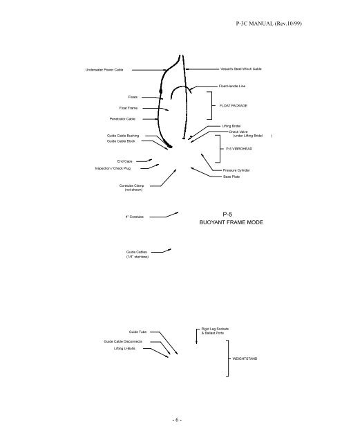
P-3C MANUAL (Rev.10/99) III. P-3C ASSEMBLY, MAIN COMPONENTS AND HANDLING. GENERAL ASSEMBLY The general drawing of the previous page illustrates the essential components of the P-5C modular vibrocorer in its buoyant frame mode. The P-3C has the same setup: 1. The new vibrohead is shipped with the check valve already properly mounted in place. A periodic inspection to insure that this unit remain tightly fastened to the vibrohead is recommended. 2. Insert and screw the guide-cable bushings, one on each side of the vibrohead, into the guide-cable threaded slot with the hex-head on the top side of the guide-cable slot. The 1/4" stainless steel guide-cable will pass through the center of the guide-cable bushing and have stainless steel eyes nicro-pressed onto each end of the wire cable. NOTE: Each set of guide-cables are intended to be used with a specific length of coretube. Extra guide-cable bushings would be required to make various length cable sets. Measuring the proper length of stainless steel cable to make a guide-cable assembly is covered on page 13. 3. Mount the coretube-clamp to the underside of the vibrohead using the two 1/2-13 plated steel bolts and two 1/2-13 stainless steel fully threaded rods. NOTE: When tightening the clamp around a coretube, first sung up all the "plated" steel nylock nuts six total (6). For final tightening, first do the four horizontal bolt drawing the jaws together and then the two vertical nuts on the threaded rods. Do not over tighten! Apply 60 to 90 ft.lb./in. Use a 1/2” drive ratchet only. Do not use an extension bar or breaker bar. NOTE: The clamp uses a combination of stainless steel bolts and plated steel nuts. When ever possible, DO NOT USE stainless bolt and stainless nuts together. With repeated use, there is a possibility that the stainless nut will seize on the stainless bolt. 4. Connect the underwater power cable to the vibrohead and to the power source. See page 5, "Specifications" for the proper voltage and current and page 10, "Connecting the Underwater Power Cable". 5. Attach the corenose to the end of the coretube. See page 11, "Corenose". 6. Add ballast to the weightstand. See page 12 "weightstand" for details on the ballast. 7. Attach the vessel's winch cable to the vibrohead. Lifting Shackles. NOTE: To prevent the loss the vibrocoring system during deployments and operations, the attachment shackles the vibrohead and the winch cable MUST have seizing wire locking the shackle-pin into the shackle's body. This connection must be checked on a regular basis. - 7 -
- Page 1 and 2: P-3C MANUAL (Rev.10/99) INDEX I. TH
- Page 3 and 4: P-3C MANUAL (Rev.10/99) The unit ca
- Page 5: P-3C MANUAL (Rev.10/99) II. MAIN VI
- Page 9 and 10: P-3C MANUAL (Rev.10/99) When submer
- Page 11 and 12: P-3C MANUAL (Rev.10/99) The XSL-4-C
- Page 13 and 14: P-3C MANUAL (Rev.10/99) WEIGHTSTAND
- Page 15 and 16: P-3C MANUAL (Rev.10/99) CONTROL BOX
- Page 17 and 18: P-3C MANUAL (Rev.10/99) IV. SOME PO
- Page 19 and 20: P-3C MANUAL (Rev.10/99) III. UNDERW
- Page 21 and 22: P-3C MANUAL (Rev.10/99) the electri
- Page 23 and 24: P-3C MANUAL (Rev.10/99) require a 3
- Page 25: P-3C MANUAL (Rev.10/99) End cap bor
- 6 -<br />
P-<strong>3C</strong> MANUAL (Rev.10/99)


