INDEX I. THE P-3C VIBROCORER - GENERAL DESCRIPTION ...
INDEX I. THE P-3C VIBROCORER - GENERAL DESCRIPTION ...
INDEX I. THE P-3C VIBROCORER - GENERAL DESCRIPTION ...

Create successful ePaper yourself
Turn your PDF publications into a flip-book with our unique Google optimized e-Paper software.
P-<strong>3C</strong> MANUAL (Rev.10/99)<br />
<strong>INDEX</strong><br />
I. <strong>THE</strong> P-<strong>3C</strong> <strong>VIBROCORER</strong> - <strong>GENERAL</strong> <strong>DESCRIPTION</strong> ............................. 2<br />
Vibrocorer drawing on sea floor; P-3 vibrocorer not shown ............................ 4<br />
II. SPECIFICATIONS ......................................................................................... 5<br />
Component drawing; P-3 vibrocorer not shown ....….…..........................….. 6<br />
III. ASSEMBLY, MAIN COMPONENTS AND HANDLING .......................... 7<br />
General Assembly ............................................................................................ 7<br />
Buoyancy Frame and Float Package ................................................................ 8<br />
Using the P-<strong>3C</strong> Coretube Clamp ..................................................................... 9<br />
Connecting the Underwater Power Cable ........................................................ 10<br />
Maintaining the Connectors and O-Rings ....................................................... 11<br />
Fitting the Corenoses (for Coretubes w/Liners) .............................................. 11<br />
Weightstand and Guide-Cables ....................................................................... 13<br />
Rigid Leg and Top Beam Assembly ................................................................ 14<br />
Control Box ...................................................................................................... 15<br />
IV. SOME POINTS TO CONSIDER BEFORE AN OPERATION ................... 17<br />
V. DEPLOYMENT OF <strong>THE</strong> P-<strong>3C</strong> VIBROCORING SYSTEM ....................... 19<br />
VI. REMARKS AND RECOMMENDATIONS ................................................. 20<br />
Appendix A: SELECTION OF LOCALLY AVAILABLE<br />
CORETUBES AND LINERS ...................................................... 24<br />
ECCENTRIC SETTINGS ………………........................................................... 25<br />
O-RING SPECIFICATIONS ………...........………………................................ 25<br />
- 1 -
P-<strong>3C</strong> MANUAL (Rev.10/99)<br />
I. <strong>THE</strong> P-<strong>3C</strong> <strong>VIBROCORER</strong>. <strong>GENERAL</strong> <strong>DESCRIPTION</strong>.<br />
The P-<strong>3C</strong> Modular Vibrocorer is the newest version of the original P-3 vibrocorer. It is<br />
designed for coring unconsolidated waterlogged sediments at sea, in lakes, rivers, harbors,<br />
ponds and wetlands. Its light weight enhances its vibratory performances and facilitates its<br />
delivery and operation in sites hard-to-reach. It is adaptable to various coring requirements<br />
through its modular components and it is well suited for hazardous environments as it is<br />
fully encapsulated without external moving parts.<br />
The letter “C” in P-<strong>3C</strong> indicates that the pressure housing is a solid casting. A cast housing<br />
eliminates all seams that requires welding. The original P-3 pressure housing was<br />
susceptible to weld fatigue.<br />
The main components of the P-<strong>3C</strong> Vibrocoring System are:<br />
the vibrohead.<br />
the "buoyant frame" with its float-package and its<br />
weightstand.<br />
a coretube, equipped with or without a plastic liner.<br />
the underwater electrical cable coming from the surface<br />
support platform to the vibrohead.<br />
the control box located between the underwater cable and<br />
the power source.<br />
The P-<strong>3C</strong> pressure housing is rated for operation in ocean depths down to 600m (2,800 ft).<br />
Under proper voltage conditions the internal vibrator motor has a 1,000 hour operating time<br />
before requiring service and lubrication. As a rule of thumb, at 2-3 minutes per core, this<br />
means some 20,000 cores.<br />
The patented "buoyant frame" allows handling of the overall system with ease and with<br />
limited drawworks and deck space. It consists of two thin cables held taut underwater<br />
between a weightstand and a float package and guiding vertically the vibrocorer. The<br />
weightstand has provisions to accommodate an extension arms and two rigid vertical legs<br />
topped with a cross-beam transforming the frame into a conventional rigid support unit for<br />
special situations, such as shallow swift waters. The P-<strong>3C</strong> can be implemented with or<br />
without the "buoyant frame". Usually, no frame is needed in calm waters to, say, 20m (65ft)<br />
depths with an anchored platform.<br />
- 2 -
P-<strong>3C</strong> MANUAL (Rev.10/99)<br />
The unit can handle coretubes from 3" (76mm) to 5" (127mm) diameter with appropriate<br />
clamps and clamp-adapters. However it comes normally equipped with a 4"(101.6mm)<br />
clamp for 4" diameter coretubes (100mm if requested).<br />
Standard 4" coretubes are of steel with a wall thickness of 0.083" to 0.125" (2.1mm to<br />
3.1mm), equipped with expendable liners of clear plastic (cellulose butyrate or<br />
polycarbonate). Aluminum thinwall 4" coretubes with a 0.120" wall thickness can be used<br />
for shorter cores of 14 ft. (4m) or less, equipped or not with liners.<br />
The P-<strong>3C</strong> eccentric settings can be modified to a low, medium or maximum setting. The<br />
medium setting is recommended for 60Hz current and the maximum setting for the 50Hz<br />
current (see next section "Specifications"). Regardless of the customer’s power source,<br />
every P-<strong>3C</strong> is shipped from the factory with the eccentrics set on medium.<br />
The depth of penetration of the coretube depends upon the force of the vibrohead, the<br />
characteristics of the coretube (material, length, wall thickness) and the characteristics of the<br />
sediment. With the P-<strong>3C</strong> vibrocorer using a 4"OD (101.6mm) coretube, we generally expect<br />
penetrations of 3 to 10 ft. (1 to 3m) in packed sands and 10 to 20ft. (3 to 6m) in mud, silt and<br />
some clays. Note that the 20ft length often used as a standard for coretubes also corresponds<br />
to the common dimension of the off-the-shelf tubes or pipes and to the maximum dimension<br />
generally accepted for international airfreight.<br />
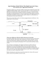
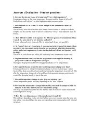
The general vibrocoring operation of the P-5C is illustrated in the following page. The P-<strong>3C</strong><br />
operates in the same manner.<br />
- 3 -
- 4 -<br />
P-<strong>3C</strong> MANUAL (Rev.10/99)
P-<strong>3C</strong> MANUAL (Rev.10/99)<br />
II. MAIN <strong>VIBROCORER</strong> SPECIFICATIONS<br />
DEPTH CAPABILITY<br />
600m (2,800 ft)<br />
OPERATING POWER REQUIREMENTS (All 3-phase) NOT STARTUP<br />
(Low Setting = 4.0 kW, 7.5 amps,<br />
230v, 50/60 Hz (Mid Setting = 5.0 kW, 8.0 amps,<br />
(High Setting = 6.0 kW, 9.0 amps,<br />
(Low Setting = 4.0 kW, 3.5 amps,<br />
440v, 50/60 Hz (Mid Setting = 5.0 kW, 4.0 amps,<br />
(High Setting = 6.0 kW, 4.5 amps,<br />
GENERATOR SIZE<br />
10.5 KVA, 18 hp GAS ENGINE<br />
CENTRIFUGAL FORCE At 60Hz At 50 Hz<br />
(1 kN = 225 lbs) Low Setting = 16.0 kN 10.9 kN<br />
Mid Setting = 20.0 kN 13.7 kN<br />
High Setting = 24.0 kN 16.4 kN<br />
VIBRATIONS PER MINUTE 3,450vpm @ 60Hz or 2,850vpm @ 50Hz<br />
APPROXIMATE WEIGHT<br />
in air (w/o ballast & coretube)<br />
submerged (w/o ballast & coretube)<br />
150 lbs (68 Kg)<br />
70 lbs (32 Kg)<br />
RECOMMENDED BALLAST (lead, scrap metal, etc.)<br />
100 lbs (45 Kg)<br />
TYPICAL CORETUBES, NOSES, and LINERS<br />
4" ALUMINUM LINERLESS CORETUBES O.D. I.D.<br />
4" Thin Wall (0.125" wall) aluminum, 1.75 lbs/ft. 4.00" (101.6mm) 3.750" (95.2mm)<br />
Rivetable Corenose (with incorporated retainer) 4.00" 3.55" (90.1mm)<br />
4" STANDARD CORETUBE FOR LINERS<br />
4" Thin Wall (0.083" wall) carbon steel, 3.47 lbs/ft, 4.00" (101.6mm) 3.834" (97.4mm)<br />
Clear Liner* , 1/16" wall, 3.75" ( 95.3mm) 3.63" (92.2mm)<br />
Rivetable Corenose (with incorporated retainer) 4.00" 3.40"<br />
(86.4mm)<br />
4" Thick Wall (.120" wall) carbon steel, 4.97 lbs/ft. 4.00" (101.6mm) 3.760" (95.5mm)<br />
Clear Liner* , 1/16" wall, 3.62" ( 92.0mm) 3.50" (88.8mm)<br />
Rivetable Corenose (with incorporated retainer) 4.00" 3.37" (85.6mm)<br />
• Standard clear liners are CAB (cellulose-acetate butyrate) and polycarbonate (Lexan).<br />
- 5 -
- 6 -<br />
P-<strong>3C</strong> MANUAL (Rev.10/99)
P-<strong>3C</strong> MANUAL (Rev.10/99)<br />
III. P-<strong>3C</strong> ASSEMBLY, MAIN COMPONENTS AND HANDLING.<br />
<strong>GENERAL</strong> ASSEMBLY<br />
The general drawing of the previous page illustrates the essential components of the P-5C<br />
modular vibrocorer in its buoyant frame mode. The P-<strong>3C</strong> has the same setup:<br />
1. The new vibrohead is shipped with the check valve already properly mounted in place. A<br />
periodic inspection to insure that this unit remain tightly fastened to the vibrohead is<br />
recommended.<br />
2. Insert and screw the guide-cable bushings, one on each side of the vibrohead, into the<br />
guide-cable threaded slot with the hex-head on the top side of the guide-cable slot. The 1/4"<br />
stainless steel guide-cable will pass through the center of the guide-cable bushing and have<br />
stainless steel eyes nicro-pressed onto each end of the wire cable. NOTE: Each set of<br />
guide-cables are intended to be used with a specific length of coretube. Extra guide-cable<br />
bushings would be required to make various length cable sets. Measuring the proper length<br />
of stainless steel cable to make a guide-cable assembly is covered on page 13.<br />
3. Mount the coretube-clamp to the underside of the vibrohead using the two 1/2-13 plated<br />
steel bolts and two 1/2-13 stainless steel fully threaded rods.<br />
NOTE: When tightening the clamp around a coretube, first sung up all the "plated" steel<br />
nylock nuts six total (6). For final tightening, first do the four horizontal bolt drawing the<br />
jaws together and then the two vertical nuts on the threaded rods. Do not over tighten!<br />
Apply 60 to 90 ft.lb./in. Use a 1/2” drive ratchet only. Do not use an extension bar or<br />
breaker bar. NOTE: The clamp uses a combination of stainless steel bolts and plated steel<br />
nuts. When ever possible, DO NOT USE stainless bolt and stainless nuts together. With<br />
repeated use, there is a possibility that the stainless nut will seize on the stainless bolt.<br />
4. Connect the underwater power cable to the vibrohead and to the power source. See page<br />
5, "Specifications" for the proper voltage and current and page 10, "Connecting the<br />
Underwater Power Cable".<br />
5. Attach the corenose to the end of the coretube. See page 11, "Corenose".<br />
6. Add ballast to the weightstand. See page 12 "weightstand" for details on the ballast.<br />
7. Attach the vessel's winch cable to the vibrohead.<br />
Lifting Shackles. NOTE: To prevent the loss the vibrocoring system during deployments<br />
and operations, the attachment shackles the vibrohead and the winch cable MUST have<br />
seizing wire locking the shackle-pin into the shackle's body. This connection must be<br />
checked on a regular basis.<br />
- 7 -
P-<strong>3C</strong> MANUAL (Rev.10/99)<br />
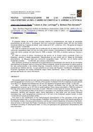
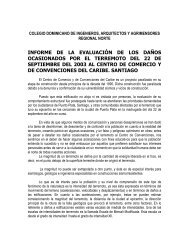
BUOYANCY FRAME AND FLOAT PACKAGE:<br />
The buoyancy frame consists of the weightstand, two guide-cables and the float package.<br />
The guide-cables are constructed using 1/4" stainless steel cable passed through the guidecable<br />
bushings (4) with a nicro-press fitting and eye on both ends. Shackled on the lower<br />
end of the guide-cable there is an 8" to 12" section of 1/4" galvanized chain (3) with a<br />
stainless steel, heavy duty<br />
clip (2). These clip the guide-cables<br />
to the weightstand's U-Bolts (1)<br />
during deployment and retrieval.<br />
The chain allows the guide-cable<br />
length can be adjusted several<br />
inches to accommodate different<br />
length corenoses or to correct<br />
an incorrectly made guide-cable<br />
length.<br />
A 12" leader section (5) allows the<br />
top of the guide-cable to be accessable<br />
during deployment and retrieval<br />
to attach the float package's Leader<br />
cable (7). At the lower end of the<br />
12" leader section is a nicro-press<br />
fitting crimped into place acting as<br />
a stopper (8).<br />
The distance between the stopper and<br />
the U-Bolt should be equal to the<br />
length of the coretube. Any minor<br />
adjustments can be made with chain<br />
by adding or removing a chain link.<br />
NOTE: It is very important to adjust<br />
the length of the guide-cables<br />
so the corenose on the end of the<br />
coretube is captured inside the<br />
weightstand's guide tube (See pg.4)<br />
by 2"-3" when the vibrohead and<br />
buoyant frame system in hanging in air.<br />
For deployment at sea, the most practical<br />
procedure is to deploy the Vibrocorer<br />
clipped with the guide-cables and weightstand, but without the float package. Lower this<br />
unit until the Vibrohead is level with a person's chest standing on the stern. At this point,<br />
clip the float package onto the guide-cable leaders and let the float package hang on the side<br />
of the vibrohead while lowering the unit the rest of the way into the water.<br />
- 8 -
P-<strong>3C</strong> MANUAL (Rev.10/99)<br />
When submerged, the float package will flip right-side up into the proper position. The<br />
stern technician can guide the Float Package into this position by hanging on to the float<br />
Package's hand rope located on top to the floats.<br />
NOTE: On one side of the float package there is a gap of approximately 3" between the<br />
floats (See drawing on page 4&5). The vessel's winch cable should positioned in this gap<br />
along with the Underwater Power Cable if possible during decent to the sea floor. When the<br />
vibrocorer reaches the sea floor the winch cable and power cable will fall sideways and not<br />
bear upon unit tilting it.<br />
USING <strong>THE</strong> P-<strong>3C</strong> CORETUBE CLAMP<br />
The P-<strong>3C</strong> clamp consists of three pieces: A Stationary Jaw, and two are the Moveable Jaws.<br />
1. Mount the coretube-clamp to the underside of the vibrohead using the two 1/2-13 plated<br />
steel bolts and two 1/2-13 stainless steel fully threaded rods. The threaded rods are screwed<br />
completely into the base of the vibrocorer and then the "Stationary" main body of the clamp<br />
- 9 -
P-<strong>3C</strong> MANUAL (Rev.10/99)<br />
is then fitted over the threaded rods. Insert the two 1/4-20 bolts on the side of the clamp's<br />
body and tighten. This locks the threaded rod's rotation. Next, using the extended socket<br />
tool provided, install the two "thin" 1/2-13 stainless steel nuts onto the rods and tighten. The<br />
"Stationary" portion of the clamp never needs to be removed unless access to the ball valve<br />
is necessary.<br />
2. Install the "Movable jaws. Put a flat washer over each threaded rod, place the first<br />
movable jaw over the rods and add another flat washer between the two jaws. Add the last<br />
flat washer and a Nylock nut onto the rods and draw the nuts up, but do not tighten them yet.<br />
3. Insert the four horizontal bolts through the two sets of jaws connecting them to each<br />
other. Snug the four nuts on the bolts to secure the stationary jaws to the movable jaws.<br />
NOTE: The clamp uses a combination of stainless steel bolts and plated steel nuts. When<br />
ever possible, DO NOT USE stainless bolt and stainless nuts together. With repeated use,<br />
there is a possibility that the stainless nut will seize on the stainless bolt.<br />
4. Insert a coretube into the clamp and into until the coretube stops at the 4"ID inside<br />
shoulder of the stationary jaw.<br />
5. When tightening the clamp around a coretube, first sung up all the "plated" steel nylock<br />
nuts six total (6). For final tightening, first do the four horizontal bolt drawing the jaws<br />
together and then the two vertical nuts on the threaded rods. Do not over tighten! Apply 60<br />
to 90 ft.lb./in. Use a 1/2” drive ratchet only. Do not use an extension bar or breaker bar.<br />
NOTE: 1. If any of the nuts & bolts associated with the coretube clamp are loosened<br />
during vibration, problems may arise: (1) The coretube may be damaged and break below<br />
the clamp, staying in the ground. (2) The amperage draw may raise and exceed the limits of<br />
the power source preventing the operation of the Vibrohead. Always use a softer steel nut<br />
on a stainless bolt.<br />
CONNECTING <strong>THE</strong> UNDERWATER POWER CABLE<br />
The Underwater Power Cable's (UPC) length, style, and manufacture is the decision of each<br />
individual customer. However, one aspect that is common with any UPC is the ability to<br />
mate the connector properly to form a watertight seal. If water should enter the mated<br />
connectors, even a single drop, damage will result causing the replacement of the<br />
connector(s) and even a section of the UPC.<br />
The P-<strong>3C</strong> Vibrohead Terminal Connector Assembly mounted on the pressure housing<br />
includes a Penetrator, a cable lead and a CCP Connector. The penetrator, supplied by<br />
Impulse Enterprise, San Diego, is a stainless steel penetrator style "bulkhead connector"<br />
MSSG-4-BCR-PNA specially modified from the MSSG series to provide the additional<br />
bore-seal O-Ring. Internally, this single penetrator is connected to both vibrator motors<br />
inside the vibrohead. Externally it is molded to a Kevlar reinforced, 12 gauge, 4 conductor<br />
neoprene cable which in turn is molded to a Impulse Epoxy XSL-4-CCP connector.<br />
- 10 -
P-<strong>3C</strong> MANUAL (Rev.10/99)<br />
The XSL-4-CCP is the connector that the UPC will mate with. The UPC must have be<br />
terminated with an XSL-4-CCR connector to mate correctly with XSL-4-CCP on the P-<strong>3C</strong><br />
Vibrohead. (See Appendix B).<br />
Assemble the connector using only a dielectric silicone O-Ring lubricant. (Refer to the<br />
below section pertaining to inspection of the O-Rings). After screwing the XSL’s locking<br />
ring into place, it is recommended to wrap electrical tape around the connection to prevent<br />
any sediment from entering the small gaps and to prevent any accidental unscrewing of the<br />
connectors while under vibration.<br />
MAINTAINING <strong>THE</strong> CONNECTORS AND O-RINGS<br />
WARNING: Do not drop a connector onto a hard surface such as the deck of a ship, steel,<br />
concrete, etc. Such an impact on the connector could cause small cracks in the epoxy body<br />
or damage the tightening rings. If a small crack is visual, replace the connector. Under<br />
pressure, water can be forced through the smallest fracture and short out the system.<br />
1. Inspect each O-Ring for damage or deformation. Replace the O-Ring if it dose not look<br />
new.<br />
2. Clean and lubricate each O-Ring before each assembly.<br />
3. Inspect and clean the insides of the mating connectors. Remove any debris, water<br />
moisture<br />
and dirt.<br />
4. During storage, protect each connector with a strong cover, such as a piece of PVC pipe.<br />
5. Do not over tighten the connectors when mated. A firm hand-twisted connection is all<br />
that is required.<br />
6. A damaged O-Ring only cost pennies, a new connector and cable cost hundreds of dollars<br />
not to mention valuable down-time.<br />
FITTING <strong>THE</strong> CORENOSE (CORETUBES WITH LINERS):<br />
The standard corenose (see drawing next page) is designed to be attached to the coretube by<br />
four (4) 3/16" diameter pop-rivets. These rivets are considered expendable for each core.<br />
The liner will slide over the first shoulder on the corenose.<br />
Preparing the Coretube:<br />
1. The coretube may need to be cut to the required length.<br />
2. Use a file to remove any burrs or turned-over edges inside and outside of the coretube at<br />
each end.<br />
3. Place the Coretube Jig over one end of the coretube and drill the first rivet hole. Insert a<br />
rivet into the hole through the jig and coretube to keep the jig from rotating while drilling<br />
the next three holes. Drill the remaining holes. Remove the Coretube Jig.<br />
4. File the burrs from the drills holes inside and outside.<br />
- 11 -
P-<strong>3C</strong> MANUAL (Rev.10/99)<br />
Assembling the Coretube, Liner and Corenose:<br />
1. Measure and cut the liner to the same length as the coretube. Insert the liner into the<br />
coretube. The liner should be 1.5" inside the coretube's end.<br />
2. Insert the corenose into the liner and coretube.<br />
3. Rotate the corenose to line up the coretube and corenose rivet holes.<br />
4. Insert the four rivets and fasten.<br />
Removing of the Corenose and Liner:<br />
1. Chisel off the rivet's aluminum head and then tap the mandrel out with a punch.<br />
2. Insert the 3/8" steel rod (using it as a lever) through the extraction holes on the end of the<br />
corenose and rotate the corenose back and forth while pulling it out of the coretube.<br />
- 12 -
P-<strong>3C</strong> MANUAL (Rev.10/99)<br />
WEIGHTSTAND & GUIDE-CABLES<br />
1. The Weightstand is designed to maintain a fixed position on the sea floor, to guide the<br />
coretube into the sediment and to stabilize the vibrohead in a vertical attitude with the<br />
assistance of the float package.<br />
2. The weightstand has two open channels to accept about 45 kilos (100 lbs - weight in<br />
water) of additional ballast. This enables the user to add extra weight when in operation and<br />
then to remove the extra weight for transportation. Scrap iron / steel may be used, such as<br />
chain, lead weights, etc.<br />
3. The two stainless steel guide cable attach to the U-bolts on top of the weightstand by<br />
means of the snap clips on each cable. The guide cables, which pass through the vibrohead<br />
by way of the two guide cable bushings and to which the float package is attached, should<br />
be about the same length as the coretube being used.<br />
4. To make a proper set of guide cables, the actual length of the stainless steel cable will be<br />
measured from the outside lip of each "eye" on each end of the cable. This measurement<br />
should be 8" shorter than the length of the coretube. At one end of the cable a 12" long<br />
section of 1/4" chain will be attached with a large snap clip. The chain will allow for cable<br />
length adjustments if the size (length) of corenoses are changed, or the next coretube may<br />
not be exactly the same length as the previous coretube.<br />
5. When the guide cables are properly adjusted, the corenose on the end of the coretube<br />
when mounted in the vibrohead should be captive inside the guide tube of the weightstand<br />
by approximately 2-3" from the top. The corenose does not protrude under the weightstand.<br />
- 13 -
P-<strong>3C</strong> MANUAL (Rev.10/99)<br />
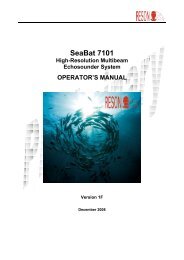
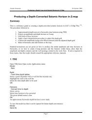
RIGID LEG AND TOP BEAM ASSEMBLY:<br />
This setup is for conditions where either a current is to swift or water may be to shallow and<br />
the vessel’s drawworks are to short. The weightstand is provided with two sockets (3.5"ID)<br />
for setting two rigid legs (standard 3.5"OD pipes) for the Rigid Leg Assembly.<br />
Follow the drawing below for the rigging.<br />
1. The best way to assemble this setup is to lay the vibrohead and captive coretube on deck<br />
with the guide wires all rigged. Have the weightstand supported on its side at its proper<br />
position at the end of the coretube. This will allow for proper measuring for the leg<br />
dimensions and support lines.<br />
2. Remove the guide wire and floats.<br />
NOTE: The legs must be cut to a<br />
length placing the top beam one foot<br />
or more above the vibrohead.<br />
Measure and cut two legs and insert<br />
them into the weightstand. Pin them<br />
into place. Place the top beam over<br />
the legs above the vibrohead.<br />
3. The 1/2-13 stainless steel threaded<br />
rod and two eye-nuts will pin each leg<br />
into the top beam. When the legs are<br />
positioned in the top beam use a 1/2”<br />
drill bit to enlarge the pin holes on the<br />
top beam while drilling into the leg.<br />
Do this from both sides of the beam.<br />
Insert the 1/2” rod into the hole and<br />
screw the eye-nuts into place. Now<br />
the legs are captivated in the<br />
assembly.<br />
4. Make the support lines from any<br />
strong line or cable. Fasten or tie the<br />
line from an eye-nuts on the top beam<br />
down to each corner of the<br />
weightstand. Do this for each corner.<br />
The assembly is complete. Deploy as<br />
usual.<br />
P5C shown<br />
- 14 -
P-<strong>3C</strong> MANUAL (Rev.10/99)<br />
CONTROL BOX:<br />
The control box (motor starter) is specially built for operating and monitoring the<br />
vibrocorer. Its components consist of the “Start” and “Stop” buttons, a selector switch for<br />
voltage, a selector switch for amperage, and the volt and amp meters.<br />
1. Wire the control box to a 3 phase power supply and to the vibrohead. Before pushing the<br />
“start” button monitor each phase of the incoming current. Use the voltage selector switch<br />
to switch between a pair of current phases. These values are between two phased, not<br />
between a single phase and neutral, and should be at least as high as the minimum voltage<br />
required to operate the vibrocorer. NOTE: Remember that there will be a current loss over<br />
the power cable, so if the vibrocorer is to operate on 230 volts the incoming power to the<br />
control box should be above 230 volts.<br />
2. The amperage meter is to monitor the current draw across each phase. All three phases<br />
should be drawing the same value at all times. If one phase is less than the other two a bad<br />
power cable may be the cause or a damaged vibrator motor. Get to know what the amperage<br />
should be during operation. If a high amperage is read on all three legs, check to see if the<br />
coretube is loose or breaking at the coretube clamp. Also, inspect the vibrator motor mount<br />
bolts for looseness. Excessive high amperage means that the vibrohead and motors are<br />
unbalanced, flopping around. When the overload protector trip off do not just reset it. Stop<br />
coring and figure out what was the cause, correct it, then continue coring. The overload is to<br />
protect your investment. Do not ignore it!<br />
- 15 -
P-<strong>3C</strong> MANUAL (Rev.10/99)<br />
MOTOR WIRING AND COLOR CODES<br />
The three phase motor has nine (9) winding leads. If a wire’s identity is lost, it can be<br />
identified by the common resistance between pairs of wire. Common resistance is: (1 & 4),<br />
(2 & 5), (3 & 6), (7 & 8), (7 & 9), (8 & 9). The color code for the wires are:<br />
1 = White, 2 = Red, 3 = Black, 4 = Orange, 5 = Purple, 6 = Yellow, 7 = Gray<br />
8 = Blue, 9 = Pink, and Neutral or Ground = Green<br />
- 16 -
P-<strong>3C</strong> MANUAL (Rev.10/99)<br />
IV. SOME POINTS TO CONSIDER BEFORE AN OPERATION<br />
Three critical areas have to be considered before operating the Vibrocorer, and they are:<br />
1. The selection and procurement of the coretubes and liners.<br />
2. The support platform (barge or vessel) and its ancillaries (drawworks).<br />
3. The power source and electrical cable.<br />
I. CORETUBES AND LINERS:<br />
Selection and Availability: First, a decision has to be made whether to use a steel coretube<br />
with liner or a bare aluminum coretube. This decision is in part a function of what is locally<br />
available. For overseas work, due to the fragility and bulkiness of liners, the best is to see if<br />
liners can be found locally off-the-shelf or can be locally extruded to custom specs then to<br />
look for the corresponding the coretubes, bearing in mind that the diameter clearance<br />
between the coretube's ID and the liner's OD should be in the order of 1-2mm (0.030-<br />
0.060"). Air shipment of a few adequate steel tubes and corenoses to fit the liners is not an<br />
expensive proposition. See Appendix A "Selection of Locally Available Coretubes and<br />
Liners".<br />
Second, a sample of the chosen coretube and liner to adapt and, if needed, fabricate<br />
matching clamps and corenoses.<br />
Length of Coretubes vs. length of sample: If a 15ft. (4.5m) core sample is required, the<br />
coretube needs to be 16 ft. (4.8m). This is because some 6" are lost when inserting the<br />
coretube into the vibrohead and another 6" are lost with the attachment of the corenose and<br />
retainer.<br />
II. VESSEL CHARACTERISTICS:<br />
The size of the vessel does not have as much relevance as does its maneuverability, although<br />
it must be large enough to support an A-frame of adequate size along with working deck<br />
space.<br />
Taking a core with P-<strong>3C</strong> is a relatively fast, but not an instantaneous operation. Due to the<br />
difference of piston or dart corers, the Vibrocorer has to stand on the sea floor for a<br />
minimum time allowing for full penetration. Two to three minutes is the average duration.<br />
Therefore the vessel must be able to maintain its position over the core site and remain on<br />
position while the vibrocorer is deployed and coring. The vibrocorer is coupled to the vessel<br />
via the winch cable and the vibrocorer's underwater electrical cable. If the vessel drifts<br />
away from the vibrocorer while it is operating on the sea floor, the tension on the winch<br />
cable can pull the vibrocorer over or the underwater electrical cable may not have sufficient<br />
length and may snap. This will damage the connectors and could cause an electrical short or<br />
damage the vibrocorer's motors.<br />
- 17 -
P-<strong>3C</strong> MANUAL (Rev.10/99)<br />
Also, if the vessel drifts or swings on its anchor chain, the vessel will not be over the unit<br />
during the extraction of the coretube from the sediment resulting in the winch cable being<br />
off the vertical and pulling the vibrocorer sideways. This can make the recovery process<br />
very difficult. Bent coretubes, loss of coretubes and samples can be expected.<br />
Consequently it is essential that the vessel have either the ability to deploy several anchors<br />
to maintain position or, in the case of deep water coring, a good real time maneuverability.<br />
Nighttime operation: During the evening hours the working area on the deck must be well<br />
lit and with lights on top of the A-frame to cover the work area behind the stern.<br />
A-frame size and load capacity: 1. Height of A-frame ("Deck Clearance"). To determine<br />
the necessary height above the deck needed for a vibrocoring operation, use the following<br />
figure:<br />
Length of coretube + 4 ft. (1.2m)<br />
The additional 4 ft. will cover the height of the vibrohead and its lifting bridle plus the<br />
shackle and lifting eye at the end of the winch cable. (Terminal eyes are often made with<br />
three cable clamps, for a total of about 10-12 inches long that will not pass through the<br />
sheave under load). Note that we endeavored to minimize the height of the vibrohead, so we<br />
recommend to minimize the height of the terminal cable hook-up for the best use of the A-<br />
frame.<br />
This measurement is made below the sheave hanging from the A-frame. Example: If a 15 ft.<br />
core sample is needed, use a 16 ft. coretube + 4 ft., thus a total of 20 ft. working height is<br />
required. Please note that if a pivoting A-frame is used, the working height is measured not<br />
when the A-frame is vertical over the deck, but rather when it is tilting over the stern<br />
clearing the deck.<br />
2. Type of A-frame or crane: A pivoting A-frame is preferred. If a fixed A-frame is used,<br />
the vessel must provide a second winch to pull the vibrocorer aboard the vessel. If a sea<br />
crane is to be used, it must be able to work at sea with the roll of the vessel not affecting the<br />
boom's position or length and it must have its own winch, not a winch at some other<br />
location.<br />
3. Load Capacity. Both the drawworks and the winch and wire cable must be able to handle<br />
a minimum working load of 2 tons. If sand is expected, a 3 ton system should be used.<br />
4. Winch Wire Type. The steel wire cable on the vessel's winch should be of a non-rotating<br />
type. During deployment and recovery, the vibrocorer has both the winch cable and the<br />
UPC attached to it and because the winch cable has the tendency to rotate when un-spooled<br />
these two cables will become entangled. The deeper the water the more this becomes a<br />
problem.<br />
- 18 -
P-<strong>3C</strong> MANUAL (Rev.10/99)<br />
III. UNDERWATER POWER CABLE & POWER REQUIREMENTS:<br />
Rossfelder Corp. will provide (upon request) a Standard Neoprene Underwater Power Cable<br />
for operations in water depths of less than 500 ft. Operations in water depths greater than<br />
500 ft. special arrangements for an armored electro-mechanical and a winch system will be<br />
required.<br />
Once again, for the P-<strong>3C</strong> Vibrocorers, the current required is:<br />
220/240 volts, 3 phase, 7.5 amps, 50-60Hz or<br />
440/480 volts, 3 phase, 5 amps, 50-60Hz.<br />
This is the voltage at the vibrohead. A voltage loss will occur over a long cable, i.e. 700<br />
ft.+ and this loss should be considered and corrected by acting at the source to remain<br />
at the end of the cable within -5% and +15% of the specified figures. Open the control<br />
box and match the rated voltage of the coil to the power source.<br />
V. DEPLOYMENT OF <strong>THE</strong> P-<strong>3C</strong> VIBROCORING SYSTEM<br />
The following describes the normal procedure for deploying and retrieving at sea the P-<strong>3C</strong><br />
vibrocoring system equipped with the buoyant frame.<br />
1. Orient the vibrohead under the vessel's A-Frame with the coretube facing the bow of the<br />
vessel. Place the weightstand next to the Vibrohead on the stern under the A-Frame along<br />
with the float package.<br />
2. Lift the vibrohead off the deck into the air while one person handles the far end of the<br />
coretube until the entire coretube is hanging under the vibrohead off the deck by one foot.<br />
Slide the weightstand under the vibrohead and lower the vibrohead & coretube while<br />
guiding the coretube into the guide tube of the weightstand until the coretube touches the<br />
deck.<br />
3. Clip the guide-cables onto the U-Bolts of the weightstand than slowly lift the entire<br />
system off the deck. NOTE: The coretube / corenose should remain captivated within the<br />
guide-tube. If not, the guide-cables are to long and require shorting.<br />
4. Deploy the vibrohead & weightstand over the stern of the vessel and lower it partially into<br />
the water, stopping when the vibrohead becomes level with a persons waist.<br />
5. Place the float package on the edge of the stern next to the vibrohead and clip the float<br />
package's attachments to the top of the guide-cables.<br />
6. Continue to lower the system into the water and drop the float package into the water.<br />
- 19 -
P-<strong>3C</strong> MANUAL (Rev.10/99)<br />
7. As the vibrocoring system is continued to be lowered to the sea floor try to maintain the<br />
UPC from becoming wrapped around the winch cable.<br />
8. When sea floor contact is made, than turn on the vibrocorer and let it operate for 2<br />
minutes than turn off the electricity. Allow the vibrator motors to slow and stop rotating<br />
before pulling the coretube out of the sediment.<br />
9. Reverse steps 1 through 6 as the system is being retrieved and placed on deck. Now<br />
remove the corenose and sediment sample.<br />
MISCELLANEOUS NOTES:<br />
FLOAT PACKAGE AND CORETUBE TILT:<br />
The float package providing a buoyancy of about 160 lbs (Heavy Duty Floats) can generally<br />
maintain the tilt of a 20ft. coretube within 5° from the vertical in currents up to 0.30 ft/sec<br />
(10 cm/sec).<br />
By increasing buoyancy with additional floats, the verticality of the coretube in swifter<br />
currents can be significantly improved, for example the tilt will remain within the same 5°<br />
from vertical:<br />
with 250 lbs buoyancy, currents up to .55 ft/sec (17cm/sec)<br />
with 400 lbs buoyancy, currents up to 1.5 ft/sec (45cm/sec)<br />
with 600 lbs buoyancy, currents up to 2.2 ft/sec (67cm/sec)<br />
However, increased buoyancy will in turn require an increased ballasting of the weightstand.<br />
It is therefore generally more practical in swift current areas to revert to the Rigid Frame<br />
mode.<br />
MEASUREMENT OF <strong>THE</strong> RATE OF PENETRATION:<br />
The lowering, landing, penetration and pull-out of the Vibrocorer can be clearly monitored<br />
and recorded with an echo-sounder placed over the stern of the vessel. The float package,<br />
vibrohead and the weightstand are excellent reflectors. In particular, it is generally possible<br />
to directly obtain from the echo-sounder a graphic record of the penetration vs. time,<br />
yielding a penetration rate which, in turn, documents the variable resistance of the recorded<br />
layers.<br />
VI. REMARKS AND RECOMMENDATIONS.<br />
1. Do not take the vibrohead apart:<br />
The electric vibrohead is delivered fully assembled and closed, ready for use. The stainless<br />
steel bulkhead penetrator connector is mounted with Loctite and is internally connected with<br />
- 20 -
P-<strong>3C</strong> MANUAL (Rev.10/99)<br />
the electric vibrators. The penetrator should not, under any circumstances, be unscrewed<br />
without risk of damaging the electrical wires and breaking its O-Ring seals.<br />
The penetrator has two O-Rings sealing it to the vibrohead. One being a bore-seal type and<br />
the second being a facial compression-seal.<br />
The two (2) End Caps are mounted with two types of O-Ring seals. One being a bore-seal<br />
type # 2-372 and the second being a groove compression-seal #2-175. The end caps are held<br />
in place with stainless V-groove bands. The end caps should not be removed, but for<br />
exceptional circumstances. In this case, follow the procedure indicated in #6 below.<br />
An inspection check port plug is provided on one (1) of the two end caps. It can be used, in<br />
case of malfunction, to check if moisture has penetrated into a pressure cylinder. The<br />
vibrohead is delivered with the vibrator's pressure cylinder under vacuum.<br />
When removing the inspection check port plug the sound of in-rushing air should be heard<br />
indicating the O-Ring seal's integrity. When replacing the inspection check port plug,<br />
inspect its single O-Ring, #3-904, for any damage and be sure to secure the plug with<br />
seizing wire, as it was when delivered. In case of vibrohead malfunction, communicate with<br />
us first. This inspection should be done after each coring project, every several days, to<br />
insure that the housing is still maintaining integrity. Tilt the housing so the plug is<br />
lower than the housing and allow any moisture to drain. No moisture should be found.<br />
If moisture is present than the housing needs to be inspected for a failed O-ring and<br />
serviced. Do not continue to operate the vibrocorer with a bad O-ring.<br />
2. Avoid connecting the Underwater Electrical Cable connections in moist or wet<br />
conditions:<br />
Moisture (marine spray, rain) can be easily introduced by accident into the connection of the<br />
vibrohead to the UPC. This can result into major problems: the blowing up of the penetrator<br />
connector or the Underwater Power Cable connector, with subsequent need for completely<br />
disassembling and reconnecting a new penetrator, or even the flooding of the vibrohead<br />
itself damaging the vibrators.<br />
Try to keep the connectors mated while at sea during operations.<br />
If by some accident, e.g. breakage or short resulting from moisture, the XSL-4-CCP from<br />
the vibrohead terminal connector assembly is damaged and need emergency repair at sea, do<br />
not try to open the housing and to remove the bulkhead connector in order to replace the<br />
entire terminal connector assembly. But rather cut the damaged XSL-4-CCP and splice a<br />
new one. This terminal assembly was designed this way to allow for such an emergency<br />
splicing. To this effect, it is recommended to have spare connectors with pigtails and<br />
splicing kits.<br />
3. Avoid the removal of any of the twelve (12) Vibrator Motor Mount Plugs.<br />
- 21 -
P-<strong>3C</strong> MANUAL (Rev.10/99)<br />
The vibrator motor has six (6) motor mount plugs, each with an O-Ring seal #2-118.<br />
4. Correct Voltage and Current is a must:<br />
The vibrator motor for the P-<strong>3C</strong> is U.S. made but designed to operate on both U.S. current<br />
(60Hz) and Foreign current (50Hz), 230 volts or 440 volts. Unlike most other motors, a<br />
Vibrator motor has to work harder due to the fact that an eccentrics weight is directly<br />
attached to the motor's "Rotor". This translates to the vibrator motor requiring a higher<br />
voltage for start-up.<br />
230 Volt 60Hz version of the P-<strong>3C</strong>: Most electric motors operate on the industrial standard<br />
of 208 volts, where as a vibrator motor requires 230 volts. The P-<strong>3C</strong> vibrohead requires 230<br />
volts for proper operations. At this voltage the vibrohead will use approximately 7.5 amps<br />
while operating depending upon the hardness of the sediment and depth of coretube's<br />
penetration.<br />
The P-<strong>3C</strong>'s vibrator motor can tolerate a variance of +15% to -5% voltage change, i.e.,<br />
265-218 volts.<br />
If a 208 voltage system is to be used, we recommend to install a "Buck & Boost<br />
Transformer" on the output side of the power source before the Vibrohead to increase the<br />
voltage to 230 volts. Please consult your electrician.<br />
440 Volt 50Hz or 480 volts 60Hz version of the P-<strong>3C</strong>: Upon request, the P-<strong>3C</strong> Vibrohead<br />
can be wired for 440/480 Volts rather than 230 Volts. At this voltage the vibrohead will use<br />
approximately 3 amps while operating depending upon the hardness of the sediment and<br />
depth of coretube's penetration.<br />
<strong>THE</strong>SE VOLTAGES ARE MEASURED AT <strong>THE</strong> VIBROHEAD AFTER <strong>THE</strong><br />
CURRENT HAS PASSED THROUGH <strong>THE</strong> UNDERWATER POWER CABLE.<br />
<strong>THE</strong> INPUT VOLTAGE INTO <strong>THE</strong> UNDERWATER POWER CABLE MAY NEED<br />
TO BE INCREASED TO COMPENSATE FOR VOLTAGE LOSS OVER A LONG<br />
CABLE, - typically 500 ft. (150m) or greater.<br />
50 Hz vs. 60 Hz Current: The P-<strong>3C</strong>, as previously mentioned, can operate on either 50 or 60<br />
Hz current, however the performance will change because the circular velocity and resulting<br />
centrifugal forces, function of the square of this velocity, will be significantly different.<br />
From 60Hz to 50Hz the force drops by 30%. This is compensated in part by changing the<br />
eccentrics settings from medium to high.<br />
5. Duration of Operating Time for the P-<strong>3C</strong> Vibrohead 30/30:<br />
The vibrator motor is designed to be operated for a 30 minute duty cycle, 30/30. This means<br />
that if the vibrohead is operated for a continuous period of 30 minutes the vibrator motor<br />
- 22 -
P-<strong>3C</strong> MANUAL (Rev.10/99)<br />
require a 30 minute cool down before more use. However, under normal vibrocoring<br />
conditions, the P-<strong>3C</strong> vibrocorer will only require 2-5 minutes of operating time to<br />
completely core the sediment or encounter refusal, so the 30/30 duty cycle does not have to<br />
be observed in this case.<br />
6. If you do have to remove the End-Caps:<br />
If you do have to remove the end-caps for some exceptional reason, for example readjusting<br />
the setting of the eccentrics in response to changing the voltage frequency of the power<br />
source, note that the end-caps should be mounted by putting the pressure housing under<br />
vacuum and that the O-Ring should be discarded and replaced by new ones because they<br />
may have been pressed into a different shape and may not provide a good round sealing<br />
section the next time around.<br />
So, before removing the end-caps, make sure to have on hand: (1) a hand-held vacuum<br />
pump with hose to fit the Inspection Port and (2) two O-rings Parker 2-372 (Piston-Seal) and<br />
(2) two 2-175 (Crush Seal) and some silicone grease.<br />
By placing the end-caps in close contact to the seal seats and starting to vacuum the housing,<br />
they should move inward then suddenly close.<br />
WARNING: PROTECT <strong>THE</strong> O-RING SEAL SEATS OF <strong>THE</strong> CYLINDER WHEN<br />
OPEN. ANY SCRATCH WILL RESULT IN A LEAK FLOODING <strong>THE</strong><br />
VIBROHEAD AND CANNOT BE REPAIRED EXCEPT BY REMACHINING <strong>THE</strong><br />
SEAT AND MACHINING A NEW END-CAP TO FIT <strong>THE</strong> INCREASED<br />
DIAMETER.<br />
- 23 -
P-<strong>3C</strong> MANUAL (Rev.10/99)<br />
APPENDIX A .<br />
SELECTION OF LOCALLY AVAILABLE<br />
CORETUBES AND LINERS.<br />
The costs of shipping over long distances the consumable tubular goods, particularly plastic<br />
liners or thinwall aluminum coretubes, could be prohibitive despite their light weight<br />
because of the need for a strong protective crate and the penalty for their bulkiness.<br />
The selection of locally available thinwall linerless expendable coretubes is relatively simple<br />
with a wall thickness from about 3% of the outside diameter for stainless or "aluminized"<br />
carbon steel, to 5% to 6% for aluminum.<br />
The selection of locally available metallic coretubes along with the plastic liners to fit them<br />
is more constrained, There is a strict clearance requirement between the outside diameter<br />
for the liner and the inside diameter of the reusable coretube that it fits. As a rule of thumb<br />
this clearance should be 3%, i.e., Liner's OD = 0.97 of the Coretube's ID. To use locally<br />
available coretubes and liners, there generally are only two alternatives:<br />
Either select an off-the-shelf coretube size and have the liners custom-made,<br />
Or select an off-the-shelf liner size and endeavor to locate a matching coretube, either in<br />
Metric or in English Units, considering that, in this case, the coretube will be able, thus the<br />
smaller number of coretubes required could usually support the import costs from abroad.<br />
In summary, the following ratios will generally be satisfactory for most application:<br />
Reusable coretube to be provided with liner:<br />
Wall thickness (steel) = 5% to 6% of the outside diameter.<br />
Wall thickness (aluminum) = 5% to 6.5% of the outside diameter.<br />
Liners for above (e.g., clear butyrate):<br />
Wall thickness = 1.5% to 2% of liner's OD.<br />
Outside diameter = 97% of the coretube's ID.<br />
The corenoses will then have to be adjusted:<br />
For expendable linerless thinwall coretube, to the ID and OD of the coretube.<br />
For coretubes with liners, to the ID of the liner and the OD of the coretube.<br />
- 24 -
P-<strong>3C</strong> MANUAL (Rev.10/99)<br />
End cap bore seal #2-372<br />
End cap compression #2-175<br />
O-RING PART NUMBERS (ALL PARKER)<br />
MSSG-4-BCR-PNA #2-017 & #2-023<br />
XSL-4-CCR #2-016<br />
XSL-4-CCP #2-017<br />
Inspection port plug #3-904 or 2-110<br />
Motor mount plug #2-118<br />
Ball Check valve #2-238 & 2-338<br />
- 25 -