Advanced Microcontroller Bus Architecture Specification
Advanced Microcontroller Bus Architecture Specification
Advanced Microcontroller Bus Architecture Specification

You also want an ePaper? Increase the reach of your titles
YUMPU automatically turns print PDFs into web optimized ePapers that Google loves.
AMBA<br />
<strong>Advanced</strong> <strong>Microcontroller</strong> <strong>Bus</strong> <strong>Architecture</strong><br />
<strong>Specification</strong><br />
Document Number: ARM IHI 0001D<br />
Issued: April 1997<br />
Copyright <strong>Advanced</strong> RISC Machines Ltd (ARM) 1997<br />
All rights reserved<br />
Proprietary Notice<br />
ARM, the ARM Powered logo and EmbeddedICE are trademarks of <strong>Advanced</strong> RISC Machines Ltd.<br />
Neither the whole nor any part of the information contained in, or the product described in, this datasheet may be<br />
adapted or reproduced in any material form except with the prior written permission of the copyright holder.<br />
The product described in this datasheet is subject to continuous developments and improvements. All particulars<br />
of the product and its use contained in this datasheet are given by ARM in good faith. However, all warranties<br />
implied or expressed, including but not limited to implied warranties or merchantability, or fitness for purpose,<br />
are excluded.<br />
This datasheet is intended only to assist the reader in the use of the product. ARM Ltd shall not be liable for any<br />
loss or damage arising from the use of any information in this datasheet, or any error or omission in such<br />
information, or any incorrect use of the product.<br />
Change Log<br />
Issue Date By Change<br />
C Sep 1995 BM/DF Updated to standard format.<br />
D Apr 1997 BM Clarity improvements, reset and test interface<br />
AMBA <strong>Specification</strong><br />
ARM IHI 0001D
AMBA <strong>Specification</strong><br />
ARM IHI 0001D
Contents<br />
TOC<br />
Contents<br />
1. Introduction 1-1<br />
1.1 Overview 1-2<br />
1.2 Objectives 1-3<br />
1.3 Terminology 1-3<br />
2. Signal Naming 2-1<br />
2.1 Signal Prefixes 2-1<br />
2.2 Signal List 2-1<br />
3. Functional Description 3-1<br />
3.1 Introduction 3-2<br />
3.2 AMBA Hierarchy 3-2<br />
3.3 <strong>Advanced</strong> System <strong>Bus</strong> Description 3-5<br />
3.4 ASB Transfers 3-7<br />
3.5 Address Decode 3-13<br />
3.6 Transfer response 3-14<br />
3.7 Multi-master operation 3-16<br />
3.8 Reset Operation 3-19<br />
3.9 <strong>Advanced</strong> Peripheral <strong>Bus</strong> (APB) 3-20<br />
AMBA <strong>Specification</strong><br />
ARM IHI 0001D<br />
Contents-i
Contents<br />
4. Signal Description 4-1<br />
4.1 Introduction 4-2<br />
4.2 Clock and Reset 4-2<br />
4.3 Transfer Type 4-3<br />
4.4 Address and Control Information 4-4<br />
4.5 Slave Select Signals 4-10<br />
4.6 Transfer response 4-13<br />
4.7 Data <strong>Bus</strong> 4-17<br />
4.8 Arbitration Signals 4-20<br />
4.9 APB Signal Description 4-21<br />
5. AMBA Components 5-1<br />
5.1 Introduction 5-2<br />
5.2 ASB <strong>Bus</strong> Slave 5-2<br />
5.3 ASB <strong>Bus</strong> Master 5-6<br />
5.4 ASB Decoder 5-17<br />
5.5 ASB Arbiter 5-25<br />
5.6 APB Bridge 5-28<br />
5.7 APB Slave 5-31<br />
6. Test Interface 6-1<br />
6.1 Introduction 6-2<br />
6.2 External Interface 6-4<br />
6.3 Test Vector Types 6-6<br />
6.4 Test Interface Controller 6-6<br />
6.5 Entering Test Mode 6-10<br />
6.6 Address Vector 6-11<br />
6.7 Control Vector 6-12<br />
6.8 Write Test Vectors 6-14<br />
6.9 Read Test Vectors 6-16<br />
6.10 Burst Vectors 6-17<br />
6.11 Changing a Burst Direction 6-19<br />
6.12 Exiting Test Mode 6-20<br />
Contents-ii<br />
AMBA <strong>Specification</strong><br />
ARM IHI 0001D
Introduction<br />
1. Introduction<br />
1<br />
Introduction<br />
1. Introduction 1-1<br />
1.1 Overview 1-2<br />
1.2 Objectives 1-3<br />
1.3 Terminology 1-3<br />
AMBA <strong>Specification</strong> 1-1<br />
ARM IHI 0001D
Introduction<br />
1.1 Overview<br />
The <strong>Advanced</strong> <strong>Microcontroller</strong> <strong>Bus</strong> <strong>Architecture</strong>, AMBA, specification defines an onchip<br />
communications standard for designing high performance 32-bit and 16-bit<br />
embedded microcontrollers.<br />
Two distinct buses are defined within the AMBA specification:<br />
• the <strong>Advanced</strong> System <strong>Bus</strong>, ASB, for high-performance system modules<br />
• the <strong>Advanced</strong> Peripheral <strong>Bus</strong>, APB, for low-power peripherals<br />
ASB supports the efficient connection of processors, on-chip memories and off-chip<br />
external memory interfaces with low-power peripheral macrocell functions. The bus<br />
also provides the test infrastructure for modular macrocell test and diagnostic access.<br />
APB is optimised for minimal power consumption and reduced interface complexity<br />
to support peripheral functions.<br />
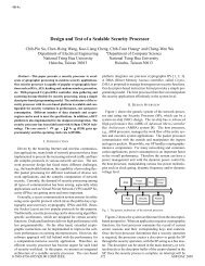
1.1.1 A typical AMBA-based microcontroller<br />
An AMBA-based microcontroller typically consists of a high-performance system<br />
'backbone' bus, able to sustain the external memory bandwidth, on which the CPU<br />
and other Direct Memory Access devices reside, plus a 'bridge' to a narrower APB bus<br />
on which the lower bandwidth peripheral devices are located.<br />
External<br />
<strong>Bus</strong><br />
Interface<br />
ARM<br />
Processor<br />
On-chip<br />
RAM<br />
<strong>Advanced</strong> System <strong>Bus</strong><br />
B<br />
R<br />
I<br />
D<br />
G<br />
E<br />
UART<br />
Timer<br />
PIO<br />
<strong>Advanced</strong> Peripheral <strong>Bus</strong><br />
Figure 1-1: A typical AMBA system<br />
The external memory interface is application specific and may only have a narrow<br />
datapath, but supports a test access mode which allows the internal ASB and APB<br />
modules to be tested in isolation with system independent test sets.<br />
1-2 AMBA <strong>Specification</strong><br />
ARM IHI 0001D
Introduction<br />
1.2 Objectives<br />
1.3 Terminology<br />
The AMBA specification has been derived to satisfy four key requirements:<br />
• To facilitate the 'right-first-time' development of embedded microcontroller<br />
products with one or more CPUs or Signal Processors.<br />
• To minimise the silicon infrastructure required to support efficient on-chip and offchip<br />
communication for both operation and manufacturing test.<br />
• To be technology independent and ensure that highly reusable peripheral and<br />
system macrocells may be migrated across a diverse range of IC processes and<br />
be appropriate for Full-Custom, Standard Cell and Gate Array technologies.<br />
• To encourage modular system design to improve 'processor independence',<br />
providing a development road-map for advanced cached CPU cores and the<br />
development of peripheral libraries.<br />
The following terms are used throughout this specification.<br />
<strong>Bus</strong> Cycle - A bus cycle is a basic unit of one bus clock period and for the purpose<br />
of protocol descriptions is defined from falling-edge to falling-edge transitions. <strong>Bus</strong><br />
signal timing is referenced to the bus cycle clock.<br />
<strong>Bus</strong> Transfer - A bus transfer is a read or write operation of a data object, which may<br />
take one or more bus cycles. The bus transfer is terminated by a 'completion'<br />
response from the addressed slave.<br />
The transfer sizes supported include byte (8-bit), halfword (16-bit) and word (32-bit)<br />
with a reserved code for future extension.<br />
<strong>Bus</strong> Master - A bus master is a system module that is able to initiate read and write<br />
operations by providing an address and control information. Only one bus master is<br />
allowed to actively use the bus at any one time.<br />
<strong>Bus</strong> Slave - A bus slave is a system module that responds to a read or write<br />
operation within a given address-space range. The bus slave signals back to the<br />
active master the success, failure or extension of the data transfer.<br />
<strong>Bus</strong> Arbiter - The bus arbiter is a module that ensures that only one bus master at a<br />
time is allowed to initiate data transfers. The arbitration scheme is not enforced such<br />
that 'highest priority' or 'fair' access algorithms may be implemented depending on the<br />
application requirements.<br />
<strong>Bus</strong> Decoder - The bus decoder is a module that performs the decoding of the<br />
transfer addresses and selects slaves appropriately. The bus decoder also ensures<br />
that the bus remains operational when no bus transfers are required.<br />
Burst Operation - A burst operation is defined as one or more data transactions<br />
initiated by a bus master which have a consistent width of transaction to an<br />
incremental region of address space. The increment step per transaction is<br />
determined by the width of transfer (byte, halfword or word).<br />
Bursts may be of arbitrary length and can be broken down into smaller packets by bus<br />
slaves which may not be able to accept burst operations, either over a particular<br />
address boundary or over a particular burst length.<br />
AMBA <strong>Specification</strong> 1-3<br />
ARM IHI 0001D
Introduction<br />
1-4 AMBA <strong>Specification</strong><br />
ARM IHI 0001D
Signal Naming<br />
2. Signal Naming<br />
2<br />
Signal Naming<br />
2. Signal Naming 2-1<br />
2.1 Signal Prefixes 2-1<br />
2.2 Signal List 2-1<br />
AMBA <strong>Specification</strong> 2-1<br />
ARM IHI 0001D
Signal Naming<br />
2.1 Signal Prefixes<br />
2.2 Signal List<br />
This section contains a brief description of the signals associated with an AMBA<br />
based system and a full description of each of the signals may be found in later<br />
sections of this document.<br />
The first letter of the signal name is used to indicate the signal connectivity:<br />
A<br />
B<br />
D<br />
P<br />
is a unidirectional signal between bus masters and the arbiter<br />
is an <strong>Advanced</strong> System <strong>Bus</strong> (ASB) signal<br />
is a unidirectional signal from the bus decoder<br />
is an <strong>Advanced</strong> Peripheral <strong>Bus</strong> (APB) signal<br />
Note: Please note that in earlier revisions of the AMBA specification the first letter of<br />
the signal name was separated from the rest of signal name by an underscore. This<br />
has now removed due to incompatibility with a number of design standards and tools.<br />
Name<br />
AGNTx<br />
<strong>Bus</strong> Grant<br />
AREQx<br />
<strong>Bus</strong> Request<br />
BA[31:0]<br />
Address <strong>Bus</strong><br />
BCLK<br />
<strong>Bus</strong> Clock<br />
BD[31:0]<br />
Data <strong>Bus</strong><br />
BERROR<br />
Error Response<br />
BLAST<br />
Last Response<br />
Description<br />
A signal from the bus arbiter to a bus master 'x' which indicates that the bus master<br />
will be granted the bus when BWAIT is LOW. There is an AGNTx signal for each<br />
bus master in the system, as well as an associated bus request signal, AREQx.<br />
A signal from bus master 'x' to the bus arbiter which indicates that the bus master<br />
requires the bus. There is an AREQx signal for each bus master in the system, as<br />
well as an associated bus grant signal, AGNTx.<br />
The system address bus, which is driven by the active bus master.<br />
This clock times all bus transfers. Both the LOW phase and HIGH phase of BCLK<br />
are used to control transfers on the bus.<br />
This is the bi-directional system data bus. The data bus is driven by the current bus<br />
master during write transfers and by the selected bus slave during read transfers.<br />
A transfer error is indicated by the selected bus slave using the BERROR signal.<br />
When BERROR is HIGH a transfer error has occurred, when BERROR is LOW<br />
then the transfer is successful. This signal is also used in combination with the<br />
BLAST signal to indicate a bus retract operation.<br />
When no slave is selected this signal is driven by the bus decoder.<br />
This signal is driven by the selected bus slave to indicate if the current transfer<br />
should be the last of a burst sequence. When BLAST is HIGH the decoder must<br />
allow sufficient time for address decoding. When BLAST is LOW, the next<br />
transfer may continue a burst sequence. This signal is also used in combination<br />
with the BERROR signal to indicate a bus retract operation.<br />
When no slave is selected this signal is driven by the bus decoder.<br />
2-2 AMBA <strong>Specification</strong><br />
ARM IHI 0001D
Signal Naming<br />
BLOK<br />
Locked Transfers<br />
BnRES<br />
Reset<br />
BPROT[1:0]<br />
Protection Control<br />
BSIZE[1:0]<br />
Transfer Size<br />
BTRAN[1:0]<br />
Transfer Type<br />
BWAIT<br />
Wait Response<br />
BWRITE<br />
Transfer Direction<br />
DSELx<br />
Slave Select<br />
PA[31:0]<br />
APB Address <strong>Bus</strong><br />
PD[31:0]<br />
APB Data <strong>Bus</strong><br />
PSELx<br />
APB Select<br />
PSTB<br />
APB Strobe<br />
PWRITE<br />
APB Transfer<br />
Direction<br />
When HIGH this signal indicates that the current transfer and the next transfer are<br />
to be indivisible and no other bus master should be given access to the bus. This<br />
signal is used by the bus arbiter.<br />
This signal is driven by the active bus master.<br />
The bus reset signal is active LOW and is used to reset the system and the bus.<br />
This is the only active LOW signal.<br />
The Protection control signals provide additional information about a bus access<br />
and are primarily intended for use by a bus decoder when acting as a basic<br />
protection unit. The signals indicate if the transfer is an opcode fetch or data<br />
access, as well as if the transfer is a supervisor mode access or user mode access.<br />
The signals are driven by the active bus master and have the same timing as the<br />
address bus.<br />
The Transfer Size signals indicate the size of the transfer, which may be byte,<br />
halfword or word.<br />
The signals are driven by the active bus master and have the same timing as the<br />
address bus.<br />
These signals indicate the type of the next transaction, which may be Addressonly,<br />
Non-Sequential or Sequential. These signals are driven by a bus master<br />
when the appropriate AGNTx signal is asserted.<br />
This signal is driven by the selected bus slave to indicate if the current transfer may<br />
complete. If BWAIT is HIGH a further bus cycle is required, if BWAIT is LOW then<br />
the transfer may complete in the current bus cycle.<br />
When no slave is selected this signal is driven by the bus decoder.<br />
When HIGH this signal indicates a write transfer and when LOW a read transfer.<br />
This signal is driven by the active bus master and has the same timing as the<br />
address bus.<br />
A signal from the bus decoder to a bus slave ‘x’ which indicates that the slave<br />
device is selected and a data transfer is required. There is a DSELx signal for<br />
each ASB bus slave.<br />
This is the APB address bus, which may be up to 32-bits wide and is driven by the<br />
peripheral bus bridge unit.<br />
The bi-directional peripheral data bus is driven by the peripheral bus bridge unit<br />
during write cycles (when PWRITE is HIGH) and by the selected peripheral bus<br />
slave during read cycles (when PWRITE is LOW). The peripheral data bus may be<br />
up to 32-bits wide.<br />
A signal from the secondary decoder, within the peripheral bus bridge unit, to<br />
each peripheral bus slave ‘x’. This signal indicates that the slave device is selected<br />
and a data transfer is required. There is a PSELx signal for each bus slave.<br />
This strobe signal is used to time all accesses on the peripheral bus. The falling<br />
edge of PSTB is coincident with the falling edge of BCLK.<br />
When HIGH this signal indicates an APB write access and when LOW a read<br />
access.<br />
AMBA <strong>Specification</strong> 2-3<br />
ARM IHI 0001D
Signal Naming<br />
2-4 AMBA <strong>Specification</strong><br />
ARM IHI 0001D
Functional Description<br />
3. Functional Description<br />
3<br />
Functional Description<br />
3. Functional Description 3-1<br />
3.1 Introduction 3-2<br />
3.2 AMBA Hierarchy 3-2<br />
3.3 <strong>Advanced</strong> System <strong>Bus</strong> Description 3-5<br />
3.4 ASB Transfers 3-7<br />
3.5 Address Decode 3-13<br />
3.6 Transfer response 3-14<br />
3.7 Multi-master operation 3-16<br />
3.8 Reset Operation 3-19<br />
3.9 <strong>Advanced</strong> Peripheral <strong>Bus</strong> (APB) 3-20<br />
AMBA <strong>Specification</strong> 3-1<br />
ARM IHI 0001D
Functional Description<br />
3.1 Introduction<br />
This section introduces the AMBA system hierarchy, defining the high performance<br />
<strong>Advanced</strong> System <strong>Bus</strong> (ASB) and the low power <strong>Advanced</strong> Peripheral <strong>Bus</strong> (APB).<br />
The ASB transfer mechanism is described, starting with a basic outline and then a<br />
more detailed explanation of the transfer types and transfer responses. This is<br />
followed by details of the arbitration and reset processes and finally APB transfers are<br />
also described.<br />
3.2 AMBA Hierarchy<br />
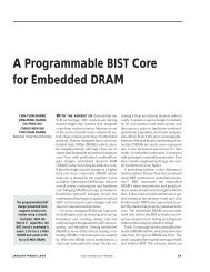
A typical AMBA-based microcontroller is shown in Figure 3-1. The processor, on-chip<br />
memory and external bus interface all reside on the high performance system bus.<br />
This bus provides a high bandwidth interface between the elements that are involved<br />
in the majority of transfers. Also located on the high performance ASB is a bridge to<br />
the lower bandwidth APB, where most of peripherals in the system reside.<br />
High<br />
Performance<br />
Processor<br />
High<br />
Bandwidth<br />
On-chip RAM<br />
UART<br />
Timer<br />
High<br />
Bandwidth<br />
Memory<br />
Interface<br />
ASB<br />
to<br />
APB<br />
Bridge<br />
DMA<br />
<strong>Bus</strong><br />
Master<br />
Keypad<br />
PIO<br />
<strong>Advanced</strong> System <strong>Bus</strong> (ASB)<br />
• High Performance<br />
• Pipelined Operation<br />
• Burst Transfers<br />
• Mulitple <strong>Bus</strong> Masters<br />
<strong>Advanced</strong> Peripheral <strong>Bus</strong> (APB)<br />
• Low Power<br />
• Latched Address and Control<br />
• Simple Interface<br />
• Suitable for Many Peripherals<br />
Figure 3-1: A typical AMBA system<br />
<strong>Advanced</strong> Peripheral <strong>Bus</strong>, APB , provides the basic peripheral macrocell<br />
communications infrastructure as a secondary bus from the higher bandwidth<br />
pipelined main system bus. Such peripherals typically have interfaces which are<br />
memory-mapped registers, have no high bandwidth interfaces and are accessed<br />
under programmed control.<br />
3-2 AMBA <strong>Specification</strong><br />
ARM IHI 0001D
Functional Description<br />
3.2.1 ASB and APB<br />
The <strong>Advanced</strong> Peripheral <strong>Bus</strong> appears as a local secondary bus that is encapsulated<br />
as a single ASB slave device. APB provides a low-power extension to the system bus<br />
which builds on ASB signals directly.<br />
The APB bridge appears as a slave module which handles the bus handshake and<br />
control signal retiming on behalf of the local peripheral bus. By defining the APB<br />
interface from the starting point of the system bus, the benefits of the system<br />
diagnostics and test methodology can be exploited.<br />
When is ASB less appropriate than APB?<br />
Building all peripherals as fully functional ASB modules is feasible but may not always<br />
be desirable:<br />
• In designs with a large number of peripheral macrocells the increased bus loading<br />
may increase power dissipation and sacrifice performance.<br />
• Where timing analysis is required, the slowest element on the bus will limit the<br />
maximum performance.<br />
• Many simple peripheral macrocells need latched addresses and control signals as<br />
opposed to the high-bandwidth macrocells which benefit from pipelined<br />
signalling.<br />
• Many peripheral functions simply require a selection "strobe" which conveys<br />
macrocell selection and read/write bus operation, without the requirement to<br />
broadcast the high frequency BCLK signal to every peripheral.<br />
• Typically macrocells will need some form of clock which comes from a centralised<br />
clock divider source. Low-power designs often benefit from a single<br />
programmable prescaler and so do not need a reference BCLK signal broadcast<br />
around the integrated circuit.<br />
When to use ASB or APB<br />
A full ASB interface is used for:<br />
• <strong>Bus</strong> masters<br />
• On-chip memory blocks<br />
• External memory interfaces<br />
• High-bandwidth peripherals with FIFO interfaces<br />
• DMA slave peripherals<br />
A simple APB interface is recommended for:<br />
• Simple register-mapped slave devices<br />
• Very low power interfaces where clocks cannot be globally routed<br />
• Grouping narrow-bus peripherals to avoid loading the system bus<br />
AMBA <strong>Specification</strong> 3-3<br />
ARM IHI 0001D
Functional Description<br />
3.2.2 ASB Components<br />
3.2.3 APB Components<br />
An ASB system design contains the following components:<br />
ASB Master - A bus master is able to initiate read and write operations by providing<br />
an address and control information. Only one bus master is allowed to actively use the<br />
bus at any one time.<br />
The system may contain one or more bus masters, typically a system would contain at<br />
least the processor and test interface, however it would also be common for a DMA<br />
(Direct Memory Access) or DSP (Digital Signal Processor) to be included as bus<br />
masters.<br />
ASB Slave - A bus slave responds to a read or write operation within a given<br />
address-space range. The bus slave signals back to the active master the success,<br />
failure or waiting of the data transfer.<br />
The external memory interface, APB bridge and any internal memory are the most<br />
common ASB slaves. Any other peripheral in the system could also be included as an<br />
ASB slave, however low bandwidth peripherals typically reside on the APB.<br />
ASB Decoder - The bus decoder performs the decoding of the transfer addresses<br />
and selects slaves appropriately. The bus decoder also ensures that the bus remains<br />
operational when no bus transfers are required.<br />
A single centralised decoder is required in all ASB implementations.<br />
ASB Arbiter - The bus arbiter ensures that only one bus master at a time is allowed<br />
to initiate data transfers. The arbitration scheme is not enforced such that 'highest<br />
priority' or 'fair' access algorithms may be implemented depending on the application<br />
requirements.<br />
An ASB would include only one arbiter, although this is would be trivial in single bus<br />
master systems.<br />
An APB implementation would contain the following components:<br />
APB Bridge - A single bridge is required to convert ASB transfers into a suitable<br />
format for the slave devices on the APB. The bridge provides latching of all address,<br />
data and control signals, as well as providing a second level of decoding to generate<br />
slave select signals for the APB peripherals.<br />
APB Slave - The APB can contain many different APB slaves.<br />
The APB slaves have the following interface specification:<br />
• Address and control valid throughout the access (unpipelined).<br />
• Zero-power interface during non-peripheral bus activity (peripheral bus is static<br />
when not in use).<br />
• Timing provided by decode with strobe timing (unclocked interface).<br />
• Write data valid for the whole access (allowing glitch-free transparent latch<br />
implementations).<br />
3-4 AMBA <strong>Specification</strong><br />
ARM IHI 0001D
Functional Description<br />
3.3 <strong>Advanced</strong> System <strong>Bus</strong> Description<br />
3.3.1 Introduction<br />
The <strong>Advanced</strong> System <strong>Bus</strong> (ASB) is a high-performance pipelined bus, which<br />
supports multiple bus masters.<br />
The basic flow of the bus operation is:<br />
• The arbiter determines which master is granted access to the bus<br />
• When granted, a master initiates transfers on the bus<br />
• The decoder uses the high order address lines to select a bus slave<br />
• The slave provides a transfer response back to the bus master and data is<br />
transferred between the master and slave.<br />
There are three types of transfer that can occur on the ASB:<br />
• Non-sequential transfers are used for single transfers or for the first transfer of<br />
a burst.<br />
• Sequential transfers are used for transfers in a burst. The address of a<br />
sequential transfer is always related to the previous transfer.<br />
• Address-only transfers are used when no data movement is required. The<br />
three main uses for Address-only transfers are for idle cycles; for bus master<br />
handover cycles; and for speculative address decoding without committing to a<br />
data transfer.<br />
AMBA <strong>Specification</strong> 3-5<br />
ARM IHI 0001D
Functional Description<br />
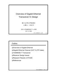
Transfer 1 Transfer 2 Transfer 3 Transfer 4<br />
BCLK<br />
BTRAN[1:0]<br />
N-TRAN S-TRAN S-TRAN S-TRAN S-TRAN<br />
BA[31:0]<br />
Addr Addr + 4 Addr + 8 Addr + C<br />
BWRITE<br />
BSIZE[1:0]<br />
BPROT[1:0]<br />
Control<br />
DSELx<br />
BWAIT<br />
BERROR<br />
BLAST<br />
WAIT DONE DONE DONE DONE<br />
BD[31:0]<br />
Data<br />
(A)<br />
Data<br />
(A +4)<br />
Data<br />
(A+8)<br />
Data<br />
(A+C)<br />
Figure 3-2: ASB Transfers<br />
Figure 3-2 above shows the use of Non-sequential and Sequential transfers to<br />
perform a burst transaction. The burst starts with a Non-sequential transfer to address<br />
A and the following sequential transfers are to successive addresses A + 4, A + 8 and<br />
A + 12.<br />
3-6 AMBA <strong>Specification</strong><br />
ARM IHI 0001D
Functional Description<br />
3.4 ASB Transfers<br />
When a master has been granted the bus it can perform the following transfers:<br />
• Non-sequential data transfer<br />
• Sequential data transfer<br />
• Address-only transfer<br />
A transfer is defined as starting at the falling edge of BCLK after the previous transfer<br />
has completed, as indicated by BWAIT being LOW, and running until the falling<br />
edge of BCLK after a complete transfer response is received, again indicated by<br />
BWAIT being LOW.<br />
The type of transfer that a bus master will perform can be determined by the value on<br />
the BTRAN signals at the start of the transfer. During the transfer the BTRAN<br />
signals will change to indicate the type of the following transfer.<br />
3.4.1 Non-sequential Transfer<br />
A Non-sequential transfer occurs for either a single transfer or the start of a burst of<br />
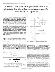
transfers. Figure 3-3 shows a typical Non-sequential read transfer including wait<br />
states.<br />
Decode<br />
Cycle<br />
Read Access<br />
BCLK<br />
BTRAN[1:0]<br />
N-TRAN<br />
BA[31:0]<br />
Addr<br />
BWRITE<br />
BSIZE[1:0]<br />
BPROT[1:0]<br />
Control<br />
DSELx<br />
BWAIT<br />
BERROR<br />
BLAST<br />
DONE WAIT WAIT WAIT DONE<br />
BD[31:0]<br />
Read<br />
Data<br />
Start of Transfer<br />
End of Transfer<br />
Figure 3-3: Non-sequential transfer<br />
AMBA <strong>Specification</strong> 3-7<br />
ARM IHI 0001D
Functional Description<br />
3.4.2 Sequential Transfer<br />
The address and control signals start to change in the BCLK HIGH phase before the<br />
transfer starts, but for a Non-sequential transfer a valid address may not be available<br />
until very late in the BCLK HIGH phase, or even until the start of the clock LOW<br />
phase at the beginning of the transfer.<br />
The decoder, which requires a stable address in order to select the correct slave, will<br />
automatically insert a wait state in the first cycle of Non-sequential transfers. This is<br />
referred to as a 'Decode Cycle' and provides an adequate time for the decoder to<br />
examine the high order address lines and assert the appropriate DSELx during the<br />
HIGH phase of the decode cycle.<br />
For the remaining cycles of the transfer, the slave will provide a transfer response and<br />
the data exchange will occur between the master and slave.<br />
Note: In certain system designs, which are typically those with a low frequency<br />
system clock, the address is valid early enough in the BCLK HIGH phase before<br />
the start of the transfer, allowing the decoder to generate a valid DSELx signal<br />
before the falling edge of BCLK.<br />
Such systems do not require the addition of a decode cycle at the start of the<br />
Non-sequential transfers and the operation of such a system is described in more<br />
detail in section 3.5, “Address Decode”.<br />
The data bus, BD[31:0], must be valid by the falling edge of BCLK at the end of the<br />
transfer. During a write cycle, the bus master is responsible for driving the data bus,<br />
which it will do from the start of the clock HIGH phase, in order that the slave may<br />
accept valid data by the falling edge of the clock. During a read cycle the appropriate<br />
slave must drive the data bus, such that it is valid by the end of the HIGH phase.<br />
Because a number of different bus slaves may drive data on to the ASB it is necessary<br />
to ensure that different slaves do not overlap when driving data onto the bus. An<br />
entire phase of non-overlap is provided as slaves/masters may not drive data during<br />
the clock LOW phase at the start of a Non-sequential transfer.<br />
As many of the bus signals are shared and have turnaround periods when there is no<br />
active driver, it is necessary to ensure that bus hold cells are provided to prevent<br />
floating levels being present on the bus.<br />
A Sequential transfer occurs when the address is related to that of the previous<br />
transfer. The control information, as indicated by BWRITE, BPROT and BSIZE, will<br />
be the same as the previous transfer.<br />
If the Sequential transfer follows a Non-sequential or another Sequential transfer, the<br />
address can be calculated by using the previous size and address. For example a<br />
burst of word accesses would be to addresses A, A+4, A+8, whereas a burst of<br />
halfword accesses would be to addresses A, A + 2, A + 4.<br />
If a Sequential transfer follows an Address-only cycle then the address will be the<br />
same as that of the Address-only cycle. This combination of an Address-only followed<br />
by Sequential allows both a single access using a Sequential transfer and also allows<br />
a burst of transfers to start with a Sequential transfer. An example of the use of an<br />
Address-only followed by Sequential of is shown later in Figure 3-6.<br />
3-8 AMBA <strong>Specification</strong><br />
ARM IHI 0001D
Functional Description<br />
Figure 3-4 shows a Sequential transfer with one wait state and it can be seen that it<br />
closely resembles a Non-sequential transfer. The main differences are:<br />
• BTRAN signals indicate a Sequential transfer<br />
• Address is always valid in the BCLK HIGH phase at the start of the transfer<br />
• Address is related to the preceding transfer<br />
• Control information remains the same as the preceding transfer<br />
• For a write the data bus is driven throughout the entire transfer<br />
The data bus, BD[31:0], can be driven throughout the entire transfer because,<br />
unlike the Non-sequential case, there is no requirement to provide a period of time to<br />
allow for bus turnaround.<br />
Read Access<br />
BCLK<br />
BTRAN[31:0]<br />
S-TRAN<br />
BA[31:0]<br />
Previous Address<br />
+ Transfer Size<br />
BWRITE<br />
BSIZE[1:0]<br />
BPROT[1:0]<br />
Control<br />
BD[31:0]<br />
Write<br />
Data<br />
BD[31:0]<br />
Read<br />
Data<br />
BWAIT<br />
BERROR<br />
BLAST<br />
DONE WAIT DONE<br />
Start of Transfer<br />
End of Transfer<br />
Figure 3-4: Sequential Transfer<br />
AMBA <strong>Specification</strong> 3-9<br />
ARM IHI 0001D
Functional Description<br />
3.4.3 Address-Only Transfer<br />
An Address-only transfer indicates that no data transaction is required. During an<br />
Address-only transfer it is possible that the address and control information may also<br />
be invalid. The only signals that must be driven to valid levels are:<br />
• BTRAN - To indicate the type of the next transfer<br />
• BLOK - To allow the arbitration process to continue<br />
As Address-only transactions do not access slaves on the bus, they only require a<br />
single cycle and therefore the BWAIT signal will be LOW. This signal is driven by the<br />
bus decoder, as no slave will be selected during the Address-only cycle. A bus<br />
master may perform a number of Address-only transfers in succession if it does not<br />
require the bus for data transfer.<br />
The Address-only transfer can actually be used in a number of different ways.<br />
• As a true idle cycle, when the bus master does not require the bus.<br />
• To speculatively broadcast an address for the next transfer, without committing to<br />
the transfer.<br />
• To provide a turnaround cycle during bus master handover.<br />
If the Address-only transfer is used as a true idle cycle then the address and control<br />
signals are not required to be valid at any point during the transfer. The BLOK signal<br />
is the only exception and must be driven to a valid level during all Address-only<br />
transfers to allow the arbitration process to continue.<br />
BCLK<br />
BTRAN[31:0]<br />
A-TRAN<br />
BLOK<br />
BWAIT<br />
BERROR<br />
BLAST<br />
DONE<br />
Decoder drives<br />
response<br />
DONE<br />
Start of Transfer<br />
End of Transfer<br />
Figure 3-5: Address-only transfer<br />
3-10 AMBA <strong>Specification</strong><br />
ARM IHI 0001D
Functional Description<br />
The second use of the Address-only transfer is to speculatively broadcast the<br />
address for a transfer, without actually committing to the transfer. This allows the<br />
address decoding to be performed by the decoder during the Address-only cycle. If<br />
the bus master then commits to the burst it is possible to start the burst with a<br />
Sequential transfer, thus removing the need for an extra decode cycle before the<br />
transfer starts.<br />
Address given during<br />
Address-Only Transfer<br />
Burst starts with<br />
Sequential Transfer<br />
BCLK<br />
BTRAN[31:0]<br />
A-TRAN<br />
S-TRAN<br />
BA[31:0]<br />
Address<br />
BWRITE<br />
BSIZE[1:0]<br />
BPROT[1:0]<br />
Control<br />
BWAIT<br />
BERROR<br />
BLAST<br />
DONE WAIT DONE<br />
Figure 3-6: Address-only transfer to start burst<br />
AMBA <strong>Specification</strong> 3-11<br />
ARM IHI 0001D
Functional Description<br />
The final use of an Address-only transfer is to provide a turnaround period during bus<br />
master handover. A bus master which becomes granted on the bus must start with an<br />
Address-only transfer and, in this case, the new bus master does not drive the<br />
address and control signals immediately, but provides a phase of turnaround before<br />
driving the signals in the LOW phase of the transfer.<br />
It is important to note that in this case the address and control information will not<br />
become valid until the LOW phase of BCLK.<br />
Address-Only Transfer<br />
for bus handover<br />
First Transfer<br />
of new bus master<br />
BCLK<br />
BTRAN[31:0]<br />
A-TRAN<br />
S-TRAN<br />
BA[31:0]<br />
Address<br />
BLOK<br />
BPROT[1:0]<br />
BSIZE[1:0]<br />
BWRITE<br />
BERROR<br />
BLAST<br />
BWAIT<br />
Control<br />
DONE DONE WAIT DONE<br />
Figure 3-7: Address-only transfer for bus master handover<br />
3-12 AMBA <strong>Specification</strong><br />
ARM IHI 0001D
Functional Description<br />
3.5 Address Decode<br />
In an AMBA system the address decoding is performed by a centralised decoder.<br />
The decoder uses the type of each transfer to determine which of the following<br />
functions should be performed:<br />
1. For an Address-only transfer - The decoder will respond with a DONE transfer<br />
response and no slaves will be selected. During Address-only transfers the<br />
decoder performs an address decode speculatively in case the Address-only<br />
transfer is followed immediately by a Sequential transfer.<br />
2. For Non-sequential transfers (or when the previous transfer was terminated with a<br />
LAST transaction response) the decoder will insert a single wait state at the start<br />
of the transfer to allow sufficient time for address decoding (although the<br />
additional wait state may not be required in all systems).<br />
The additional wait state inserted by the decoder is referred to as a 'Decode<br />
Cycle' and during the decode cycle no select signals, DSELx, are asserted.<br />
In the second cycle of the transfer the decoder will either select the appropriate<br />
slave or provide an ERROR transfer response.<br />
An ERROR response is provided in the following circumstances:<br />
• There are no slaves present at the address of the transfer.<br />
• The transfer is to a protected region of memory.<br />
• The alignment of the transfer is not supported by the memory system.<br />
In the more usual case of a valid transfer, the decoder will assert the appropriate<br />
slave DSELx signal and allow the selected slave to provide the transfer<br />
response for the remaining cycles of the transfer.<br />
3. For Sequential transfers the decoder asserts the appropriate DSELx signal and<br />
the selected slave provides the transfer response. It is not necessary for the<br />
decoder to decode the address as this will have been performed in a previous<br />
Non-sequential or Address-only transfer.<br />
As the decoder does not perform an address decode on Sequential transfers it is<br />
necessary for the slave to provide a LAST transfer response if a transfer is about to<br />
cross a memory boundary. The decoder is also responsible for generating an internal<br />
version of the LAST signal when the decoder detects that a Sequential transfer will<br />
cross a memory boundary.<br />
The insertion of a decode cycle (as described in step 2) on Non-sequential transfers<br />
can be used to improve the performance of the system. In a typical design the time<br />
required for address decoding will increase the critical path of an access to a slave and<br />
often result in the need for additional wait states. The decoder can be used to reduce<br />
this overhead by automatically inserting a decode cycle on Non-sequential transfers<br />
only, but allowing Sequential transfers to complete without additional wait states.<br />
In some systems, typically those with a low clock frequency, additional wait states are<br />
not required for address decoding and in such a systems the decoder may be<br />
simplified, such that both Sequential and Non-Sequential transfers occur without the<br />
addition of a decode cycle.<br />
AMBA <strong>Specification</strong> 3-13<br />
ARM IHI 0001D
Functional Description<br />
3.6 Transfer Response<br />
For every transfer that is initiated by a bus master a response must be generated and<br />
this is provided either by the decoder or by the selected bus slave. The transfer<br />
response is provided using the BWAIT, BERROR and BLAST signals, which are<br />
driven during the LOW phase of the clock.<br />
Figure 3-8 shows an example of how the transfer response is used to insert three wait<br />
states in order to extend a transfer.<br />
BCLK<br />
BTRAN[1:0]<br />
S-TRAN<br />
BA[31:0]<br />
Addr<br />
BD[31:0]<br />
Data<br />
BWAIT<br />
BERROR<br />
BLAST<br />
WAIT WAIT WAIT DONE<br />
Start of Transfer<br />
End of Transfer<br />
Figure 3-8: Transfer response<br />
The following transfer responses are available:<br />
WAIT<br />
DONE<br />
ERROR<br />
LAST<br />
RETRACT<br />
The transfer must be extended before it can complete.<br />
The transfer has completed successfully.<br />
The transfer has completed, but an error has occurred. The error<br />
condition should be signalled to the bus master so that it is aware the<br />
transfer has been unsuccessful.<br />
The transfer has completed successfully, but the slave is unable to<br />
accept further burst transfers or a memory boundary has been<br />
reached. This response is identical to DONE for the bus master, but<br />
indicates to the decoder that it must insert a decode cycle at the start<br />
of the next transfer.<br />
The transfer has not yet completed, so the bus master should retry<br />
the transfer. The Retract response can be used by a slave to signal to<br />
a bus master that the transfer can complete, but this may take a<br />
number of bus cycles.<br />
Using the Retract response prevents the bus from being locked up by a transfer<br />
which may take a long time to complete and frees the bus for use by a higher priority<br />
bus master.<br />
3-14 AMBA <strong>Specification</strong><br />
ARM IHI 0001D
Functional Description<br />
Unlike the other response codes, which take a single cycle, the RETRACT response is<br />
a two stage response, as shown in Figure 3-9. In the first stage the slave signals to<br />
bus master that a retract is going to take place, using the RETNEXT response<br />
(BWAIT, BLAST and BERROR all HIGH), and in the second stage the transfer is<br />
completed when the slave provides the RETRACT response (BWAIT LOW , BLAST<br />
and BERROR both HIGH). This two stage response provides the bus master with<br />
adequate warning that it should not consider the transfer to have completed when<br />
the BWAIT signal goes LOW.<br />
Current<br />
Transfer<br />
Next<br />
Transfer<br />
BCLK<br />
BA[31:0]<br />
Address<br />
Retract Next<br />
Cycle<br />
Retract<br />
BWAIT<br />
BLAST<br />
BERROR<br />
BD[31:0]<br />
Figure 3-9: Retract operation<br />
All bus masters must support the retract mechanism, however not all slaves are<br />
required to implement the retract response. Typically, a retract response would only<br />
be provided by a slave which does not have a short guaranteed completion time and<br />
hence could deadlock the bus for a significant period of time.<br />
For most transfers the response will be provided by the selected bus slave, however<br />
the decoder provides the response when:<br />
• The transfer is Address-only<br />
• The transfer is to an area of memory where there are no bus slaves<br />
• An access violation occurs to a protected region of memory<br />
AMBA <strong>Specification</strong> 3-15<br />
ARM IHI 0001D
Functional Description<br />
3.7 Multi-master operation<br />
The AMBA bus specification supports multiple bus masters on the high performance<br />
<strong>Advanced</strong> System <strong>Bus</strong> (ASB). A simple two wire request/grant mechanism is<br />
implemented between the arbiter and each bus master. The arbiter ensures that only<br />
one bus master is active on the bus and also ensures that when no masters are<br />
requesting the bus a default master is granted.<br />
The specification also supports a shared lock signal. This allows bus masters to<br />
indicate that the current transfer is indivisible from the following transfer and will<br />
prevent other bus masters from gaining access to the bus until the locked transfers<br />
have completed.<br />
Efficient arbitration is important to reduce "dead-time" between successive masters<br />
being active on the bus. The bus protocol supports pipelined arbitration, such that<br />
arbitration for the next transfer is performed during the current transfer.<br />
The arbitration protocol is defined, but the prioritisation is flexible and left to the<br />
application. Typically, however, the Test Interface would be given the highest priority<br />
to ensure test access under all conditions. Every system must also include a deafult<br />
bus master, which is granted the bus when no bus masters are requesting it.<br />
The request signal, AREQx, from each bus master to the arbiter indicates that the<br />
bus master requires the bus. The grant signal from the arbiter to the bus master,<br />
AGNTx, indicates that the bus master is currently the highest priority master<br />
requesting the bus.<br />
The bus master:<br />
• Must drive the BTRAN signals during BCLK HIGH when AGNTx is HIGH<br />
• Will become granted when AGNTx is HIGH and BWAIT is LOW on a rising edge<br />
of BCLK.<br />
The shared bus lock signal, BLOK, indicates to the arbiter that the following transfer<br />
is indivisible from the current transfer and no other bus master should be given<br />
access to the bus.<br />
A bus master must always drive a valid level on the BLOK signal when granted the<br />
bus to ensure the arbitration process can continue, even if the bus master is not<br />
performing any transfers.<br />
3-16 AMBA <strong>Specification</strong><br />
ARM IHI 0001D
Functional Description<br />
3.7.1 Arbiter<br />
The arbiter functions as follows:<br />
1. <strong>Bus</strong> masters assert AREQx during the HIGH phase of BCLK.<br />
2. The arbiter samples all AREQx signals on the falling edge of BCLK.<br />
3. During the LOW phase of BCLK the arbiter also samples the BLOK signal and<br />
then asserts the appropriate AGNTx signal.<br />
If BLOK is LOW, then the arbiter will grant the highest priority bus master.<br />
If BLOK is HIGH then the arbiter will keep the same bus master granted.<br />
The arbiter can update the grant signals every bus cycle, however a new bus master<br />
can only become granted and start driving the bus when the current transfer<br />
completes, as indicated by BWAIT being LOW. Therefore, it is possible for the<br />
potential next bus master to change during waited transfers.<br />
The BLOK signal is ignored by the arbiter during the single cycle of handover<br />
between two different bus masters.<br />
If no bus masters are requesting the bus then the arbiter must grant the default bus<br />
master.<br />
The arbitration protocol is defined, but the prioritisation is flexible and left to the<br />
application. A simple fixed priority scheme may be used, alternatively a more complex<br />
scheme can be implemented if required by the application.<br />
3.7.2 <strong>Bus</strong> Master Handover<br />
<strong>Bus</strong> master handover occurs when a bus master, which is not currently granted the<br />
bus, becomes the new granted bus master.<br />
A bus master becomes granted when AGNTx is HIGH and BWAIT is LOW. AGNT<br />
HIGH indicates the bus master is currently the highest priority master requesting the<br />
bus and BWAIT LOW indicates the previous transfer has completed.<br />
Figure 3-10 shows the bus master handover process.<br />
1. When AGNTx is asserted a bus master must drive the BTRAN signals during<br />
BCLK HIGH.<br />
This may continue for many cycles if the previous transfer is waited.<br />
Prior to handover BTRAN must indicate an Address-only cycle as the new bus<br />
master must commence with an Address-only cycle to allow for bus turnaround.<br />
2. When the previous transfer completes the new bus master will become granted.<br />
3. In the last clock HIGH phase of the previous transfer the address bus will stop<br />
being driven by the previous bus master.<br />
4. The new bus master starts to drive the address bus and control signals during the<br />
clock LOW phase.<br />
5. The first transfer may then commence in the following bus cycle.<br />
AMBA <strong>Specification</strong> 3-17<br />
ARM IHI 0001D
Functional Description<br />
C0 C1 C2 C3 C4<br />
Previous transfer<br />
New master granted<br />
BCLK<br />
AREQ<br />
AGNT<br />
BTRAN[1:0]<br />
A-TRAN A-TRAN A-TRAN S-TRAN<br />
BA[31:0]<br />
Previous transfer<br />
address<br />
Address<br />
BD[31:0]<br />
Previous transfer<br />
data<br />
Data<br />
BERROR<br />
BLAST<br />
BWAIT<br />
Last transfer<br />
completes<br />
Decoder drives<br />
response<br />
Slave drives<br />
response<br />
WAIT WAIT DONE DONE DONE<br />
3.7.3 Default <strong>Bus</strong> Master<br />
Figure 3-10: <strong>Bus</strong> master handover<br />
During a waited transfer, bus master handover may be delayed and it is possible that<br />
the AGNTx to a particular bus master may be asserted and then negated, if another<br />
higher priority bus master then requests the bus, before the current transfer has<br />
completed.<br />
Every system must be designed with a single default bus master, which will be<br />
granted when no other bus master is requesting the bus. The default bus master is<br />
responsible for driving the following signals to ensure the bus remains active.<br />
• BTRAN must be driven to indicate Address-only transfer<br />
• BLOK must be driven LOW<br />
3-18 AMBA <strong>Specification</strong><br />
ARM IHI 0001D
Functional Description<br />
3.8 Reset Operation<br />
3.8.1 Exit from Reset<br />
The reset signal, BnRES, is active LOW and may be asserted asynchronously to<br />
guarantee the bus is in a safe state. During reset the following actions occur on the<br />
bus:<br />
• The arbiter grants the default bus master<br />
• The default bus master must:<br />
- Drive BTRAN to indicate Address-only transfer<br />
- Drive BLOK LOW to allow arbitration<br />
• All other bus masters tri-state shared bus signals<br />
• The decoder must:<br />
- De-assert all slave select signals, DSELx<br />
- Provide the appropriate transfer response<br />
• All slaves tri-state shared bus signals<br />
Figure 3-11 below shows an example of the exit from reset sequence.<br />
1. During cycle C1 BnRES is de-asserted during the clock LOW phase.<br />
2. During the clock HIGH phase of cycle C1 the default bus may drive the BTRAN<br />
signal to indicate that it wishes to start a transfer.<br />
3. The transfer will start during cycle C2 and in the example shown the transfer is<br />
waited and continues into cycle C3.<br />
C0 C1 C2 C3<br />
BCLK<br />
BnRES<br />
BTRAN[1:0]<br />
A-TRAN<br />
S-TRAN<br />
BA[31:0]<br />
Address<br />
BWAIT<br />
BERROR<br />
BLAST<br />
DONE DONE WAIT DONE<br />
Figure 3-11: Exiting from reset<br />
AMBA <strong>Specification</strong> 3-19<br />
ARM IHI 0001D
Functional Description<br />
3.9 <strong>Advanced</strong> Peripheral <strong>Bus</strong> (APB)<br />
The <strong>Advanced</strong> Peripheral <strong>Bus</strong> (APB) provides a low power extension to the higher<br />
performance ASB. APB transfers are non-pipelined with address, PA[31:0], and<br />
control, PSELx and PWRITE, information set-up before the start of the transfer and<br />
held valid throughout the transfer.<br />
Typically not all 32 -bits of the address bus are implemented. All peripherals should be<br />
aligned to word boundaries and hence the lowest two bits of the address are not<br />
required. The high order address lines are not required as the address decode for the<br />
peripheral bus is carried out within the bridge unit and signalled to the slaves using<br />
the PSELx signals. Of the other address lines, only those required by the slaves in a<br />
particular system need to be implemented.<br />
During write accesses the data bus, PD[31:0], is also valid throughout the transfer.<br />
For read accesses the APB slave must supply valid data before the falling edge of<br />
PSTB, which is coincident with the falling edge of BCLK.<br />
P1 P2 P3 P4<br />
BCLK<br />
PSTB<br />
PSELxx<br />
PA[31:0]<br />
Address<br />
PWRITE<br />
PD[31:0]<br />
Write<br />
Data<br />
PD[31:0]<br />
Read<br />
Data<br />
Figure 3-12: APB Access<br />
Figure 3-12 shows the basic APB transfer, which operates as follows:<br />
1. At the start of phase P1 the address, select and write signals all become valid for<br />
the access. If the transfer is a write access, then the data will also become valid in<br />
phase P1.<br />
3-20 AMBA <strong>Specification</strong><br />
ARM IHI 0001D
Functional Description<br />
During phase P1, the slave which is selected can decode the address and write<br />
signal to generate an internal write strobe qualifier for the register that is about to<br />
be accessed.<br />
2. At the start of phase P2 the timing strobe, PSTB, is asserted. The address and<br />
write signal are setup well in advance of the rising edge of PSTB, as is the data in<br />
the case of a write access.<br />
3. Throughout P2 and P3 the address, write signal and the data (in the case of a<br />
write access) remain stable and valid.<br />
PSTB can be used in conjunction with PSELx and the appropriate address<br />
lines in a number of different ways:<br />
• As a clock enable, for either rising or falling edge triggered registers<br />
• Directly as a clock, for either rising or falling edge triggered registers<br />
• As a transparent latch clock enable, using BCLK as the primary clock<br />
• Directly as a transparent latch clock<br />
4. For a read access, the slave must drive valid data by the falling edge of PSTB.<br />
The slave may use PSTB, qualified with PSELx, as the data bus tri-state enable<br />
control.<br />
5. At the end of the transfer the address and control information remains stable<br />
throughout phase P4, providing guaranteed hold time for all APB slaves.<br />
AMBA <strong>Specification</strong> 3-21<br />
ARM IHI 0001D
Functional Description<br />
3-22 AMBA <strong>Specification</strong><br />
ARM IHI 0001D
Signal Description<br />
4. Signal Description<br />
4<br />
Signal Description<br />
4. Signal Description 4-1<br />
4.1 Introduction 4-2<br />
4.2 Clock and Reset 4-2<br />
4.3 Transfer Type 4-3<br />
4.4 Address and Control Information 4-4<br />
4.5 Slave Select Signals 4-10<br />
4.6 Transfer response 4-13<br />
4.7 Data <strong>Bus</strong> 4-17<br />
4.8 Arbitration Signals 4-20<br />
4.9 APB Signal Description 4-21<br />
AMBA <strong>Specification</strong> 4-1<br />
ARM IHI 0001D
Signal Description<br />
4.1 Introduction<br />
This section provides more detailed information all the AMBA signals, including their<br />
intended use and phase accurate timing requirements.<br />
As many of the bus signals are shared and have turnaround periods when there is no<br />
active driver, it is necessary to ensure that bus hold cells are provided to prevent<br />
floating levels being present on the bus.<br />
4.2 Clock and Reset<br />
4.2.1 Clock<br />
4.2.2 Reset<br />
BCLK is the primary clock, which is used to time all bus transfers. Both edges of the<br />
clock are used.<br />
A single active LOW reset signal, BnRES, is supported which is used to reset the<br />
bus. The reset signal may be asserted LOW asynchronously during either clock<br />
phase, but is always de-asserted during the LOW phase of BCLK.<br />
BCLK<br />
BnRES<br />
Figure 4-1: Reset Signal<br />
During reset the following actions occur on the bus:<br />
• The arbiter grants the default bus master<br />
• The default bus master must:<br />
- Drive BTRAN to indicate Address-only transfer<br />
- Drive BLOK LOW to allow arbitration<br />
• All other bus masters tri-state shared bus signals<br />
• The decoder must:<br />
- De-assert all slave select signals, DSELx<br />
- Provide the appropriate transfer response<br />
• All slaves tri-state shared bus signals<br />
4-2 AMBA <strong>Specification</strong><br />
ARM IHI 0001D
Signal Description<br />
The BnRES signal may be used to reset the bus during time-out conditions.<br />
In the majority of bus masters and slaves the BnRES signal will be used to reset both<br />
the bus interface and the main core of the component. However, it is acceptable for<br />
some system elements, such as a real-time clock, to use BnRES to only reset the<br />
bus interface. Such system elements would typically have a second reset input to<br />
allow the component core to be reset at initial power-up and for testing purposes.<br />
4.3 Transfer Type<br />
Before a transfer starts the bus master indicates the type of the transfer, of which<br />
there are three basic types; Address-only, Non-sequential and Sequential.<br />
The following table shows the encoding of the BTRAN[1:0] signals:<br />
BTRAN Transfer Type Description<br />
[1] [0]<br />
0 0 Address-only Used when no data movement is required. The<br />
three main uses for Address-only transfers are for<br />
idle cycles; for bus master handover cycles; and<br />
for speculative address decoding without<br />
committing to a data transfer.<br />
0 1 - Reserved<br />
1 0 Non-sequential Used for single transfers or for the first transfer of<br />
a burst. The address of the transfer is unrelated to<br />
the previous bus access.<br />
1 1 Sequential Used for successive transfers in a burst. The<br />
address of a sequential transfer is always related<br />
to the previous transfer.<br />
Table 4-1: BTRAN encoding<br />
From the table it can be seen that BTRAN[1] can be used to determine that a data<br />
transfer is required next cycle.<br />
The BTRAN signals are driven by a bus master during the HIGH phase of BCLK<br />
when the AGNTx input is HIGH.<br />
BCLK<br />
BTRAN[1:0]<br />
Transfer<br />
Type<br />
Figure 4-2: BTRAN timing<br />
In a multi-master system, the bus master that drives BTRAN may change during an<br />
extended transfer. Therefore, BTRAN must only be considered valid when the<br />
previous transfer has completed, as indicated by BWAIT LOW.<br />
AMBA <strong>Specification</strong> 4-3<br />
ARM IHI 0001D
Signal Description<br />
4.4 Address and Control Information<br />
The address and control signals are:<br />
• BA[31:0]<br />
• BWRITE<br />
• BSIZE[1:0]<br />
• BPROT[1:0]<br />
BA[31:0] - Address <strong>Bus</strong><br />
The 32 bit address bus, BA[31:0], provides the address of the transfer. All transfers<br />
are memory mapped and therefore all memory and peripherals within the system must<br />
have an address range within which they are accessed. The decoder uses the<br />
address bus (usually the higher order bits) to determine which bus slave is to be<br />
accessed.<br />
BWRITE - Transfer Direction<br />
The BWRITE signal is used to indicate the direction of the transfer. When BWRITE<br />
is LOW the transfer is a read access and when BWRITE is HIGH the transfer is a write<br />
access.<br />
BWRITE<br />
Transfer Direction<br />
0 Read Transfer<br />
1 Write Transfer<br />
Table 4-2: BWRITE encoding<br />
4-4 AMBA <strong>Specification</strong><br />
ARM IHI 0001D
Signal Description<br />
BSIZE[1:0] - Transfer Size<br />
BSIZE[1:0] encodes the size of a transfer. Byte, halfword and word are all defined,<br />
with the final encoding being reserved for future use.<br />
BSIZE<br />
[1] [0]<br />
Transfer Width<br />
0 0 Byte (8 bits)<br />
0 1 Halfword (16 bits)<br />
1 0 Word (32 bits)<br />
1 1 Reserved<br />
Table 4-3: BSIZE encoding<br />
When performing transfers that are narrower than the data bus, such as a byte or<br />
halfword transfer, the bus master may replicate the data across the bus, making the<br />
bus master effectively bi-endian. When responding to read cycles, a typical slave will<br />
not replicate the data on the bus and therefore it is important that the master is<br />
expecting data on the same byte lane as that which the slave is driving.<br />
BPROT[1:0] - Protection Information<br />
The bus master may use the BPROT signals to provide additional information about<br />
the transfer it is performing. This information is primarily intended for use by the<br />
decoder when it is acting as a bus protection unit and the majority of bus slaves will<br />
not use these signals.<br />
BPROT<br />
[1] [0]<br />
Transfer Privilege<br />
- 0 Opcode Fetch<br />
- 1 Data Access<br />
0 - User Access<br />
1 - Supervisor Access<br />
Table 4-4: BPROT encoding<br />
AMBA <strong>Specification</strong> 4-5<br />
ARM IHI 0001D
Signal Description<br />
4.4.1 Address and Control Signal Timing<br />
The address and control information is generated by the bus master from the rising<br />
edge of BCLK. However, the timing of the address and control information is<br />
considered separately for Non-sequential and Sequential transfer types. This is<br />
because a bus master will typically have a significantly different timing parameters in<br />
each case.<br />
It is a common characteristic that bus masters will have fast address and control output<br />
valid timings for Sequential transfers, as shown in Figure 4-3. This is because a bus<br />
master is usually able to generate a sequential address well before the start of the<br />
transfer and therefore the output valid time from the bus master is mainly dependent<br />
on the time required to drive the new value onto the bus.<br />
BCLK<br />
BTRAN[1:0]<br />
S-TRAN<br />
BA[31:0]<br />
Sequential<br />
Address<br />
BWRITE<br />
BSIZE[1:0]<br />
BPROT[1:0]<br />
Sequential<br />
Control<br />
Start of Transfer<br />
Figure 4-3: Sequential address and control timing<br />
4-6 AMBA <strong>Specification</strong><br />
ARM IHI 0001D
Signal Description<br />
For Non-sequential transfers the bus master will often have significantly slower output<br />
valid times for address and control signals, compared to those for Sequential transfers<br />
and this is shown in Figure 4-4.<br />
BCLK<br />
BTRAN[1:0]<br />
N-TRAN<br />
BA[31:0]<br />
Non-Sequential<br />
Address<br />
BWRITE<br />
BSIZE[1:0]<br />
BPROT[1:0]<br />
Non-Sequential<br />
Control<br />
Start of Transfer<br />
Figure 4-4: Non-sequential address and control<br />
timing with low frequency clock<br />
In systems where the clock frequency is approaching the maximum possible, it is<br />
common for the address and control output valid time to be greater than a clock<br />
phase, thus resulting in the address not becoming valid until the BCLK LOW phase<br />
at the start of the transfer, as shown in Figure 4-5.<br />
BCLK<br />
BTRAN[1:0]<br />
N-TRAN<br />
BA[31:0]<br />
Non-Sequential<br />
Address<br />
BWRITE<br />
BSIZE[1:0]<br />
BPROT[1:0]<br />
Non-Sequential<br />
Control<br />
Start of Transfer<br />
Figure 4-5: Non-sequential address and control<br />
timing with high frequency clock<br />
AMBA <strong>Specification</strong> 4-7<br />
ARM IHI 0001D
Signal Description<br />
For Address-only transfers the address and control information is not valid. In the<br />
special case of the Address-only followed immediately by a Sequential transfer, as<br />
shown in Figure 4-6, the bus master generates the address and control information<br />
during the Address-only transfer, such that it is valid throughout the BCLK HIGH<br />
phase before the start of the Sequential transfer.<br />
BCLK<br />
BTRAN[1:0]<br />
A-TRAN<br />
S-TRAN<br />
BA[31:0]<br />
Address<br />
BWRITE<br />
BSIZE[1:0]<br />
BPROT[1:0]<br />
Control<br />
Start of Transfer<br />
Figure 4-6: Address-only followed by Sequential transfer<br />
address and control timing<br />
4-8 AMBA <strong>Specification</strong><br />
ARM IHI 0001D
Signal Description<br />
4.4.2 Tri-state enable of Address and Control Signals<br />
A bus master may only drive the address and control signals when the bus master is<br />
granted the bus. To allow for a period of bus turnaround, when a bus master is first<br />
granted the bus it will not drive in the BCLK HIGH phase before the first transfer.<br />
Instead, the bus master must always start a period of bus ownership with an Addressonly<br />
transfer and the address and control signals are not driven until the BCLK LOW<br />
phase of the Address-only transfer.<br />
Previous bus master<br />
New bus master<br />
BCLK<br />
BTRAN[1:0]<br />
A-TRAN<br />
S-TRAN<br />
BA[31:0]<br />
BWRITE<br />
BSIZE[1:0]<br />
BPROT[1:0]<br />
Previous transfer<br />
completes<br />
Address-only after<br />
bus turnaround<br />
Sequential<br />
transfer<br />
Figure 4-7: Address and control signals during bus master handover<br />
For multi-master systems:<br />
• When the master is first granted, the signals are not driven until the first LOW<br />
phase of BCLK when the master becomes active on the bus.<br />
• When a bus master is granted the bus it drives the address and control signals<br />
during both phases of BCLK.<br />
• The bus master stops driving the signals in the last BCLK HIGH phase, when the<br />
master loses mastership of the bus.<br />
AMBA <strong>Specification</strong> 4-9<br />
ARM IHI 0001D
Signal Description<br />
4.5 Slave Select Signals<br />
Each ASB slave in the system has a DSEL select input signal. This signal indicates<br />
that the slave is responsible for supplying a transfer response and that a data transfer<br />
is required. The signal name DSELx is used to indicate the DSEL signal to slave ‘x’.<br />
There is one DSELx signal for each slave on the ASB and these signals are<br />
generated by the decoder. Only one DSELx signal will be active during a transfer<br />
and there may be cycles when no DSELx signal is active, such as during Addressonly<br />
transfers.<br />
DSELx changes during the BCLK HIGH phase before the start of a transfer and<br />
remains valid during the transfer. It will change for the next transfer in the BCLK HIGH<br />
phase following a transfer response with BWAIT LOW.<br />
When designing a system there are two options for the implementation of an ASB<br />
decoder, either with or without Decode cycles. This choice is fixed at the design<br />
stage and will be based on a timing analysis of the system. In general, a system that is<br />
operating up to the maximum speed of the processor will require Decode cycles; it is<br />
only those systems which operate at a frequency significantly lower than the possible<br />
maximum that do not require Decode cycles.<br />
The ‘Decoder with Decode Cycles’ and ‘Decoder without Decode Cycles’ cases are<br />
discussed separately below.<br />
Decoder with Decode Cycles<br />
In systems with a high clock frequency the critical path to decode the address and<br />
select a slave within a single clock phase tends to limit the maximum bus clock speed.<br />
In such systems the decoder can be used to automatically insert a wait state, or<br />
“Decode Cycle”, at the start of every Non-sequential transfer. This implementation<br />
allows Sequential transfers to continue to operate without the addition of a wait state,<br />
as it is known that the address decoding critical path can be avoided on Sequential<br />
transfers, thus resulting in an overall improvement in bus bandwidth<br />
4-10 AMBA <strong>Specification</strong><br />
ARM IHI 0001D
Signal Description<br />
For Non-sequential transfers DSELx is asserted in the BCLK HIGH phase during<br />
the Decode cycle, as shown in Figure 4-8 below.<br />
Decode Cycle<br />
BCLK<br />
BTRAN[31:0]<br />
N-TRAN<br />
BA[31:0]<br />
Non-Sequential<br />
Address<br />
DSELx<br />
BWAIT<br />
BERROR<br />
BLAST<br />
WAIT WAIT DONE<br />
Start of Transfer<br />
End of Transfer<br />
Figure 4-8: Select signal timing with decode cycle<br />
When decode cycles are implemented the timing of DSELx is dependent only on<br />
BTRAN[1:0] and there is no timing dependency on the address and control<br />
signals. This is because no DSELx signals are asserted for Address-only transfers;<br />
for a Non-sequential transfer the Decode cycle is inserted to provide an entire phase<br />
for the address and control information to become valid; and for Sequential transfers<br />
the address and control information from the previous cycle is used.<br />
AMBA <strong>Specification</strong> 4-11<br />
ARM IHI 0001D
Signal Description<br />
Decoder without Decode Cycles<br />
In systems with a low clock frequency the address and control information will be valid<br />
in time to decode the address and select a slave within a single clock phase. In such<br />
systems a Decode cycle is not required.<br />
The select signal becomes valid during the HIGH phase of BCLK before the transfer<br />
commences and remains valid throughout the transfer, until the HIGH phase of the<br />
last cycle.<br />
BCLK<br />
BTRAN[31:0]<br />
Transfer<br />
Type<br />
BA[31:0]<br />
Address<br />
DSELx<br />
BWAIT<br />
BERROR<br />
BLAST<br />
WAIT<br />
DONE<br />
Start of Transfer<br />
End of Transfer<br />
Figure 4-9: Select signal timing<br />
When the decoder does not insert decode cycles, the timing of DSELx becomes<br />
dependent on the timing of the address and control signals generated by the<br />
currently granted bus master.<br />
4-12 AMBA <strong>Specification</strong><br />
ARM IHI 0001D
Signal Description<br />
4.6 Transfer Response<br />
The transfer response signals are used by slave devices to indicate the status of a<br />
transfer.<br />
A valid transfer response must be provided during the LOW phase of BCLK.<br />
Whenever a slave is selected (as indicated by DSELx being asserted) the slave must<br />
provide the response. When no slave is selected, for example during an Addressonly<br />
transfer, the response is provided by the decoder.<br />
BWAIT - Wait Response<br />
BWAIT is used to indicate when a transfer may complete. BWAIT is asserted HIGH<br />
when the slave requires extra bus cycles to complete the current transfer. BWAIT<br />
LOW indicates that the transfer may finish. Whether or not the transfer has completed<br />
successfully can only be determined by examining the other transfer response<br />
signals.<br />
BERROR - Error Response<br />
An error condition is signalled by the BERROR signal. This may be used to indicate a<br />
failed transfer, a transfer to an address where there is no slave device or a protection<br />
error.<br />
Many simple bus slaves will not implement error logic and will therefore have a fixed<br />
response of BERROR LOW.<br />
BERROR is also used in conjunction with BLAST to indicate a retract operation.<br />
When both these signals are HIGH this indicates that a bus retract is required.<br />
BLAST - Last Response<br />
BLAST is used to signal if the current transfer must be the last of a burst. This would<br />
typically be used to prevent a burst from continuing over a page boundary or other<br />
burst length limit.<br />
BLAST is used by the decoder to make sure that the following transfer has the same<br />
characteristics as a Non-sequential type transfer, rather than a burst transfer. Typically<br />
this involves ensuring there is adequate time to perform a new address decode.<br />
Many bus slave devices will be able to accept any number of burst accesses and<br />
these slaves will have a fixed response of BLAST LOW.<br />
BLAST is also used in conjunction with BERROR to indicate a retract operation.<br />
When both these signals are HIGH this indicates that a bus retract is required.<br />
AMBA <strong>Specification</strong> 4-13<br />
ARM IHI 0001D
Signal Description<br />
<strong>Bus</strong> Retract<br />
Slaves that cannot guarantee to complete transfers in a small number of wait states<br />
can potentially block the bus and stop higher priority transfers occurring. To prevent<br />
such slaves impacting the overall system latency a retract mechanism is provided<br />
which allows a slave to indicate that a transfer is unable to complete at present, but the<br />
operation should be retried until it is able to complete successfully.<br />
A retract is performed in a two stage process, as shown in Figure 4-10. First the slave<br />
responds with BWAIT, BLAST and BERROR all HIGH, which indicates that a<br />
retract is to occur and the transfer will finish in the next bus cycle.<br />
In the second cycle the transfer response is BWAIT LOW , BLAST and BERROR<br />
both HIGH. This indicates that the transfer has retracted and the bus is free to be used<br />
by higher priority bus masters.<br />
Current<br />
Transfer<br />
Next<br />
Transfer<br />
BCLK<br />
BA[31:0]<br />
Address<br />
Retract Next<br />
Cycle<br />
Retract<br />
BWAIT<br />
BLAST<br />
BERROR<br />
BD[31:0]<br />
Figure 4-10: Retract operation<br />
Basic slaves, which have a guaranteed completion time, do not need to support the<br />
bus retract mechanism.<br />
4-14 AMBA <strong>Specification</strong><br />
ARM IHI 0001D
Signal Description<br />
Response Combinations<br />
Table 4-5 below shows the combinations of the three slave transfer response signals.<br />
BWAIT BLAST BERROR Status Description<br />
0 0 0 DONE Complete<br />
Transfer Successful<br />
0 0 1 ERROR Complete<br />
Transfer Error<br />
0 1 0 LAST Complete<br />
Cannot continue with Burst<br />
0 1 1 RETRACT Complete<br />
<strong>Bus</strong> Retract<br />
1 0 0 WAIT Incomplete<br />
Insert Wait Cycle<br />
1 0 1 - Reserved<br />
1 1 0 - Reserved<br />
1 1 1 RETNEXT <strong>Bus</strong> Retract Next Cycle<br />
Table 4-5: Transfer response Combinations<br />
To ensure that the bus remains synchronised, a transfer response must be driven<br />
every cycle. During bus transfers, when a slave is selected and its appropriate<br />
DSELx signal is asserted, the slave is responsible for driving the transfer response<br />
signals.<br />
The bus decoder is responsible for driving the transfer response signals during:<br />
• Address-only Transfers<br />
• Decode Cycles<br />
• Transfers to an address space where no slave is defined<br />
• Transfers to protected areas, when the access permissions are not met<br />
• Un-aligned transfers which are not supported by the memory system<br />
AMBA <strong>Specification</strong> 4-15<br />
ARM IHI 0001D
Signal Description<br />
Transfer response Timing<br />
The transfer response signals must be set up valid before the rising edge of BCLK.<br />
The signals are not driven during the HIGH phase of BCLK to allow an entire phase of<br />
turnaround between signal drivers.<br />
BCLK<br />
BTRAN[1:0]<br />
Transfer<br />
Type<br />
BA[31:0]<br />
Address<br />
BWAIT<br />
BLAST<br />
BERROR<br />
BD[31:0]<br />
Data<br />
Figure 4-11: Transfer response signal timing<br />
4-16 AMBA <strong>Specification</strong><br />
ARM IHI 0001D
Signal Description<br />
4.7 Data <strong>Bus</strong><br />
The bi-directional data bus, BD[31:0], is used to transfer data between bus masters<br />
and slaves. The size and direction of the transfer is given by the control signals, as<br />
described in section 4.4, Address and Control Information.<br />
The data bus must not be driven during the first BCLK LOW phase of a Nonsequential<br />
transfer. It may be driven, by the appropriate master or slave, at all other<br />
times except reset.<br />
• During a write transfer,<br />
The master drives the data bus during all phases of the transfer, except the<br />
first BCLK LOW phase of a Non-sequential transfer.<br />
The slave does not drive the bus.<br />
• During a read transfer,<br />
The master does not drive the data bus.<br />
The slave must drive the data bus during the last BCLK HIGH phase of the<br />
transfer. For the rest of the transfer, the slave may drive the data bus or leave<br />
it tri-state, with the provision that it is not driven during the first BCLK LOW<br />
phase of a Non-sequential transfer.<br />
The following diagrams show some examples of how the data bus is driven.<br />
Figure 4-12 shows the example of a Non-sequential write transfer. The data bus is<br />
driven by the bus master, except for the BCLK LOW phase of the first cycle. Not<br />
driving the data bus at the start of Non-sequential transfers provides a full phase of<br />
turnaround between different data bus drivers.<br />
BCLK<br />
BTRAN[1:0]<br />
N-TRAN<br />
BA[31:0]<br />
Address<br />
BWRITE<br />
BD[31:0]<br />
Data<br />
Figure 4-12: Non-sequential write transfer<br />
AMBA <strong>Specification</strong> 4-17<br />
ARM IHI 0001D
Signal Description<br />
When a write transfer is extended using BWAIT, the data remains valid through the<br />
BCLK LOW phase of the extra cycles that are required to complete the transfer, as<br />
shown in Figure 4-13.<br />
BCLK<br />
BTRAN[1:0]<br />
N-TRAN<br />
BA[31:0]<br />
Address<br />
BWRITE<br />
BWAIT<br />
BD[31:0]<br />
Data<br />
Figure 4-13: Extended write transfer<br />
For Sequential transfers the bus master may drive data during the LOW phase of<br />
BCLK at the start of the transfer, as shown in Figure 4-14. This is permitted as a<br />
phase of turnaround is not required for Sequential transfers.<br />
BCLK<br />
BTRAN[1:0]<br />
S-TRAN<br />
BA[31:0]<br />
Address<br />
BWRITE<br />
BD[31:0]<br />
Data<br />
Figure 4-14: Sequential write transfer<br />
4-18 AMBA <strong>Specification</strong><br />
ARM IHI 0001D
Signal Description<br />
During read cycles the slave drives the data bus and, as in the write cycle case, for<br />
Non-sequential transfers the data bus is not driven in the BCLK LOW phase of the<br />
first cycle. The bus slave may then drive the bus throughout the rest of the transfer.<br />
There is no requirement for the slave to drive the data bus throughout the transfer.<br />
The only requirement is that the data is driven such that it is valid by the end of the last<br />
BCLK HIGH phase of the transfer.<br />
BCLK<br />
BTRAN[1:0]<br />
Transfer<br />
Type<br />
BA[31:0]<br />
Address<br />
BWRITE<br />
BD[31:0]<br />
Data<br />
Figure 4-15: Read transfer<br />
AMBA <strong>Specification</strong> 4-19<br />
ARM IHI 0001D
Signal Description<br />
4.8 Arbitration Signals<br />
AREQx - <strong>Bus</strong> Request<br />
AREQx is the request signal from a master to the arbiter which indicates that the<br />
master requires the bus. Each master has an AREQx signal, which changes during<br />
the HIGH phase of BCLK.<br />
AGNTx - <strong>Bus</strong> Grant<br />
The grant signal from the arbiter to a bus master indicates that the bus master is<br />
currently the highest priority master requesting the bus. There is an AGNTx signal for<br />
each bus master in the system.<br />
It is important to note that AGNTx does not indicate which master is currently granted<br />
the bus. Instead, it shows which master is currently the highest priority and at the<br />
completion of a transfer, as indicated by BWAIT LOW, the master which has AGNTx<br />
asserted is granted the bus.<br />
AGNTx is changed by the arbiter during the LOW phase of BCLK and remains valid<br />
through the HIGH phase.<br />
When AGNTx is HIGH, the master must:<br />
• Drive the BTRAN signals during BCLK HIGH.<br />
• Become granted when BWAIT is LOW.<br />
BLOK - <strong>Bus</strong> Lock<br />
BLOK is the shared bus lock signal. This signal indicates the following transfer is<br />
indivisible from the current transfers and no other bus master should be given access<br />
to the bus.<br />
A master must always drive a valid level on the BLOK signal when granted the bus,<br />
even if the master is not performing any transfers. This is necessary to ensure the<br />
arbitration process can continue.<br />
If BLOK is LOW the arbiter will grant the highest priority master requesting the<br />
bus.<br />
If BLOK is HIGH the arbiter will keep the same master granted.<br />
BLOK is sampled by the arbiter during the LOW phase of BCLK and it must be valid<br />
such that the arbiter can generate valid AGNTx outputs before the rising edge of<br />
BCLK. BLOK is ignored by the arbiter during the bus master handover cycle.<br />
4-20 AMBA <strong>Specification</strong><br />
ARM IHI 0001D
Signal Description<br />
4.9 APB Signal Description<br />
PSTB - Peripheral Strobe<br />
The Peripheral Strobe signal is used to time all accesses on the peripheral bus. The<br />
falling edge of PSTB is aligned with the falling edge of BCLK.<br />
PA[31:0] - Peripheral Address <strong>Bus</strong><br />
The peripheral address bus is driven by the peripheral bus bridge unit. A full 32-bit<br />
peripheral address is not typically required and only the address lines used by the<br />
slave devices would be implemented. APB peripherals are accessed on word<br />
boundaries and the lowest two bits of the address bus, PA[1:0], are not usually<br />
required.<br />
The peripheral address will become valid before PSTB goes HIGH and remain valid<br />
after PSTB goes LOW.<br />
PSELx - Peripheral Select<br />
A PSELx signal exits for each peripheral bus slave. It is within the peripheral bus<br />
bridge unit and indicates that slave device ‘x’ is selected and a data transfer is<br />
required.<br />
This signal has the same timing as the peripheral address bus. It will become valid<br />
before PSTB goes HIGH and remain valid after PSTB goes LOW.<br />
PWRITE - Peripheral Transfer Direction<br />
When HIGH, this signal indicates a write cycle and when LOW a read cycle. This signal<br />
has the same timing as the peripheral address bus, it will become valid before PSTB<br />
goes HIGH and remain valid after PSTB goes LOW.<br />
PD[31:0] - Peripheral Data <strong>Bus</strong><br />
The bi-directional peripheral data bus is driven by the peripheral bus bridge unit<br />
during write cycles (when PWRITE is HIGH) . It will become valid before PSTB goes<br />
HIGH and remain valid after PSTB goes LOW.<br />
During read cycles (when PWRITE is LOW) the data is driven by the selected slave<br />
and must be valid before the falling edge of PSTB.<br />
The falling edge of PSTB is aligned with the falling edge of BCLK.<br />
ASB Signals<br />
If required, APB peripherals may also make use of common ASB signals, such as<br />
BCLK and BnRES.<br />
AMBA <strong>Specification</strong> 4-21<br />
ARM IHI 0001D
Signal Description<br />
4.9.1 APB Write Cycle<br />
The APB write cycle, as shown in Figure 4-16, has all the APB signals set up before<br />
the strobe and held valid after the strobe. The falling edge of the strobe is derived<br />
from the falling edge of the main system clock, BCLK.<br />
BCLK<br />
PSTB<br />
PSELxx<br />
PA[31:0]<br />
Address<br />
PWRITE<br />
PD[31:0]<br />
Data<br />
Figure 4-16: APB Write Cycle<br />
4-22 AMBA <strong>Specification</strong><br />
ARM IHI 0001D
Signal Description<br />
4.9.2 APB Read Cycle<br />
Figure 4-17 shows an APB read cycle, which has the address and control set up<br />
before the strobe and held valid after the strobe. There is no requirement to drive the<br />
data throughout the access, but read data must be set up and valid prior to the falling<br />
edge of the strobe, which will be coincident with the falling edge of BCLK.<br />
BCLK<br />
PSTB<br />
PSELxx<br />
PA[31:0]<br />
Address<br />
PWRITE<br />
PD[31:0]<br />
Data<br />
Figure 4-17: APB Read Cycle<br />
AMBA <strong>Specification</strong> 4-23<br />
ARM IHI 0001D
Signal Description<br />
4-24 AMBA <strong>Specification</strong><br />
ARM IHI 0001D
AMBA Components<br />
5. AMBA Components<br />
5<br />
AMBA Components<br />
5. AMBA Components 5-1<br />
5.1 Introduction 5-2<br />
5.2 ASB <strong>Bus</strong> Slave 5-2<br />
5.3 ASB <strong>Bus</strong> Master 5-6<br />
5.4 ASB Decoder 5-17<br />
5.5 ASB Arbiter 5-25<br />
5.6 APB Bridge 5-28<br />
5.7 APB Slave 5-31<br />
AMBA <strong>Specification</strong> 5-1<br />
ARM IHI 0001D
AMBA Components<br />
5.1 Introduction<br />
This section describes each of the elements in an AMBA system and provides the<br />
generic timing parameters that are required to analyse an AMBA design.<br />
The following notation is used for the timing parameters:<br />
Tis - Input Setup Time<br />
Tih - Input Hold Time<br />
Tov - Output Valid Time<br />
Toh - Output Hold Time<br />
Unless otherwise stated, the timing parameters apply to both the rising and falling<br />
edges of the signal. Tri-state enable and disable times are not explicitly specified. All<br />
tri-state disable times must be less than a phase of BCLK to prevent bus clash<br />
occurring. In certain cases the tri-state enable time may need to be factored in to the<br />
output valid time if the enabling of the tri-state driver is the dominant factor.<br />
5.2 ASB <strong>Bus</strong> Slave<br />
5.2.1 Interface Diagram<br />
An ASB bus slave responds to transfers initiated by bus masters within the system.<br />
The slave uses a DSEL select signal from the decoder to determine when it should<br />
respond to a bus transfer and all of the other signals that are required for the transfer,<br />
such as the address and control information, will be generated by the bus master.<br />
The decoder greatly simplifies the slave interface and removes the need for the slave<br />
to understand the different types of transfer that may occur on the bus.<br />
The diagram below shows an ASB bus slave interface.<br />
Select<br />
DSEL<br />
Address<br />
and<br />
Control<br />
BA[31:0]<br />
BWRITE<br />
BSIZE[1:0]<br />
ASB<br />
Slave<br />
BWAIT<br />
BERROR<br />
BLAST<br />
Transfer<br />
Response<br />
Reset &<br />
Clock<br />
BnRES<br />
BCLK<br />
BD[31:0]<br />
Data<br />
Figure 5-1: ASB Slave Interface<br />
5-2 AMBA <strong>Specification</strong><br />
ARM IHI 0001D
AMBA Components<br />
5.2.2 <strong>Bus</strong> Slave Interface Description<br />
Transfer Response<br />
A slave must provide a transfer response in the LOW phase of BCLK when DSEL is<br />
asserted. Using the BWAIT, BERROR and BLAST signals one of the following<br />
responses must be generated.<br />
WAIT<br />
DONE<br />
LAST<br />
ERROR<br />
The transfer must be extended before it can complete.<br />
The transfer has completed successfully.<br />
The transfer has completed successfully, but the slave is unable to<br />
accept further burst transfers or a memory boundary has been reached.<br />
The transfer has not completed successfully. The error condition will be<br />
signalled to the bus master so that it is aware the transfer has not<br />
completed correctly.<br />
RETRACT The transfer has not yet completed, so the bus master should retry the<br />
transfer. The Retract response is used by a slave to prevent the bus from<br />
being locked up by a transfer which may take many cycles to complete.<br />
Many slaves will only use the WAIT and DONE responses and in this case when a<br />
transfer response is supplied both BERROR and BLAST will be LOW.<br />
When the slave is not selected, as indicated by DSEL LOW, the transfer response<br />
signals must be tri-state. The response signals must also be tri-state during reset.<br />
Data<br />
The slave interface is implemented as a simple state machine, operating from the<br />
falling edge of the clock to determine when data transfer can occur. During reset the<br />
state machine enters the NOT_SELECTED state.<br />
DSEL<br />
NOT_SELECTED<br />
!DSEL<br />
SELECTED<br />
Figure 5-2: ASB Slave <strong>Bus</strong> Interface State Machine<br />
For write transfers the slave samples the data on the falling edge of the clock when in<br />
the SELECTED state. If required, the slave may extend the transfer using the transfer<br />
response signals described above.<br />
For read transfers the slave must drive the data bus during the last clock HIGH phase<br />
of the transfer.<br />
If the transfer is extended, by the insertion of wait cycles, then the slave may either<br />
drive the data bus during the additional cycles of the transfer, or alternatively it may<br />
leave the data bus tri-state until the last phase of the transfer.<br />
AMBA <strong>Specification</strong> 5-3<br />
ARM IHI 0001D
AMBA Components<br />
5.2.3 Timing Diagrams<br />
To avoid the slave having to determine whether the transfer is Sequential or Nonsequential<br />
it is usually simpler to design a slave which does not drive the data bus<br />
during the first phase of any transfer.<br />
During reset or when the slave is NOT_SELECTED the data bus must be tri-state.<br />
The timing parameters related to an access to an ASB bus slave are shown in Figure<br />
5-3 below.<br />
BCLK<br />
t clkl<br />
t clkh<br />
BnRES<br />
t ihnres<br />
t isnres<br />
DSEL<br />
t isdsel<br />
t ihdsel<br />
BA[31:0]<br />
Address<br />
t isa<br />
t iha<br />
BWRITE<br />
BSIZE[1:0]<br />
Control<br />
BD[31:0]<br />
Write<br />
t isctl t ihctl<br />
t isdw<br />
t ihdw<br />
Data<br />
BD[31:0]<br />
Read<br />
Data<br />
t ovdr<br />
BWAIT<br />
BERROR<br />
BLAST<br />
t ovresp<br />
t ohresp<br />
t ohdr<br />
Figure 5-3: ASB Slave Transfer<br />
5-4 AMBA <strong>Specification</strong><br />
ARM IHI 0001D
AMBA Components<br />
5.2.4 Timing Parameters<br />
The timing parameters related to an ASB bus slave are given in the following two<br />
tables, the first is for input signals, the second for output signals. Bi-directional signals<br />
can be found in both tables.<br />
Parameter<br />
Tclkl<br />
Tclkh<br />
Tisnres<br />
Tihnres<br />
Tisdsel<br />
Tihdsel<br />
Tisa<br />
Tiha<br />
Tisctl<br />
Tihctl<br />
Tisdw<br />
Tihdw<br />
Description<br />
BCLK LOW time<br />
BCLK HIGH time<br />
BnRES de-asserted setup to rising BCLK<br />
BnRES de-asserted hold after falling BCLK<br />
DSEL setup to falling BCLK<br />
DSEL hold after rising BCLK<br />
BA[31:0] setup to falling BCLK<br />
BA[31:0] hold after rising BCLK<br />
BWRITE and BSIZE[1:0] setup to falling BCLK<br />
BWRITE and BSIZE[1:0] hold after rising BCLK<br />
For write transfers, BD[31:0] setup to falling BCLK<br />
For write transfers, BD[31:0] hold after falling BCLK<br />
Table 5-1: ASB Slave Input Parameters<br />
Parameter<br />
Tovresp<br />
Tohresp<br />
Tovdr<br />
Tohdr<br />
Description<br />
BWAIT, BERROR and BLAST valid after falling BCLK<br />
BWAIT, BERROR and BLAST hold after rising BCLK<br />
For read transfers, BD[31:0] valid after rising BCLK<br />
For read transfers, BD[31:0] hold after falling BCLK<br />
Table 5-2: ASB Slave Output Parameters<br />
It is interesting to note that if the bus slave is designed such that the decoder,<br />
address and control signals are all sampled on the falling edge of BCLK then an entire<br />
phase of input hold time is guaranteed by the bus protocol.<br />
It is also possible to ensure an entire phase of hold time is provided on the data bus,<br />
by inserting an extra wait state into the transfer.<br />
AMBA <strong>Specification</strong> 5-5<br />
ARM IHI 0001D
AMBA Components<br />
5.3 ASB <strong>Bus</strong> Master<br />
5.3.1 Interface Diagram<br />
An ASB bus master has the most complex bus interface in an AMBA system. Typically<br />
an AMBA system designer would use pre-designed bus masters and therefore would<br />
not need to be concerned with the detail of the bus master interface.<br />
A bus master interface may also include a slave interface, either for test or for<br />
programming the operation of the bus master. In such cases a number of the interface<br />
signals will become shared between the master interface and slave interface.<br />
The interface diagram of an ASB bus master shows the main signal groups.<br />
Arbiter<br />
Grant<br />
AGNT<br />
AREQ<br />
BLOK<br />
Arbiter<br />
BTRAN[1:0]<br />
Transfer<br />
Type<br />
Transfer<br />
Response<br />
BWAIT<br />
BERROR<br />
BLAST<br />
ASB<br />
Master<br />
BA[31:0]<br />
BWRITE<br />
BSIZE[1:0]<br />
Address<br />
and<br />
Control<br />
BPROT[1:0]<br />
Reset &<br />
Clock<br />
BnRES<br />
BCLK<br />
BD[31:0]<br />
Data<br />
Figure 5-4: ASB <strong>Bus</strong> Master Interface Diagram<br />
5-6 AMBA <strong>Specification</strong><br />
ARM IHI 0001D
AMBA Components<br />
5.3.2 <strong>Bus</strong> Master Interface Description<br />
The bus master interface consists of two state machines. The first state machine<br />
determines if the master is currently granted the bus and the second, more complex,<br />
state machine is used to control the bus interface of the master.<br />
Granted State Machine<br />
The Granted state machine is used to determine whether or not the bus master has<br />
been granted the bus. It runs of the rising edge of BCLK and has only two states<br />
GRANTED and NOT_GRANTED. The state diagram is shown below.<br />
BWAIT + !AGNT<br />
BWAIT + AGNT<br />
NOT_GRANTED<br />
Granted = 0<br />
!BWAIT & AGNT<br />
!BWAIT & !AGNT<br />
GRANTED<br />
Granted = 1<br />
Figure 5-5: <strong>Bus</strong> Master Granted State Machine<br />
The output from the state machine is the Granted signal, which is used in the main<br />
bus master state machine.<br />
It is important to note that the AGNT signal may be asserted for a number of clock<br />
cycles, but it is only when AGNT is asserted and BWAIT is LOW that the bus master<br />
actually becomes GRANTED.<br />
An important design consideration is that the state machine may be asychronously<br />
reset into either state depending on the value of the AGNT signal. During reset one<br />
bus master in the system is set as the default bus master, as indicated by AGNT<br />
being asserted during reset, and will be reset in to the GRANTED state. All other bus<br />
masters will be reset into the NOT_GRANTED state.<br />
AMBA <strong>Specification</strong> 5-7<br />
ARM IHI 0001D
AMBA Components<br />
<strong>Bus</strong> Interface State Machine<br />
The main bus interface state machine is falling edge triggered and contains six states.<br />
The entire state diagram, as shown in Figure 5-6, is quite complex but can be<br />
considered in four quadrants:<br />
No Transfer Request<br />
Not Granted<br />
Transfer Request<br />
Not Granted<br />
No Transfer Request<br />
Granted<br />
Transfer Request<br />
Granted<br />
The "Transfer Request, Granted " quadrant contains three states, which handle bus<br />
turn around and the retract operation.<br />
The two signals internal bus master signals Granted and Request control the<br />
majority of the transitions around the state diagram. Granted is generated from the<br />
simpler state machine described above and Request is generated directly by the<br />
bus master. Request is asserted HIGH when the bus master requires a transfer on<br />
the bus and is LOW when the bus master does not need access to the bus.<br />
The only time when a transition around the state diagram is not controlled by<br />
Granted and Request is when the bus master is in the ACTIVE state. In this state<br />
the transition to the next state is determined by the transfer response that is received.<br />
WAIT, DONE, LAST, ERROR and RETNEXT shown in the diagram correspond to the<br />
encodings of the transfer response signals.<br />
5-8 AMBA <strong>Specification</strong><br />
ARM IHI 0001D
AMBA Components<br />
No Transfer Request<br />
Not Granted<br />
Transfer Request<br />
Not Granted<br />
!Granted &<br />
!Request<br />
IDLE<br />
!Granted & Request<br />
HOLD<br />
!Granted<br />
Granted &<br />
Request<br />
Granted &<br />
!Request<br />
Granted<br />
!Granted<br />
!Granted &<br />
!Request<br />
BUSIDLE<br />
!Granted &<br />
Request<br />
Granted<br />
& Request<br />
WAIT<br />
HANDOVER<br />
Granted Granted !Granted<br />
RETNEXT<br />
ACTIVE<br />
RETRACT<br />
Granted & !Request<br />
Granted &<br />
!Request<br />
DONE +<br />
LAST +<br />
ERROR<br />
Granted & Request<br />
No Transfer Request<br />
Granted<br />
!Granted & !Request<br />
!Granted & Request<br />
Transfer Request<br />
Granted<br />
Figure 5-6: <strong>Bus</strong> Master Main State Machine<br />
Note that the state diagram assumes that once the bus master has made a request for<br />
a transfer, as indicated by Request, then Request will remain asserted until the<br />
bus master has performed a transfer.<br />
AMBA <strong>Specification</strong> 5-9<br />
ARM IHI 0001D
AMBA Components<br />
As the main bus master state machine is operating from the falling edge of the clock it<br />
is necessary to use latched versions of the transfer response signals BWAIT,<br />
BERROR and BLAST to control the exit from the ACTIVE state.<br />
The reset conditions are not shown on the state diagram and, in a similar manner to<br />
the granted state machine, the main bus master state machine has a complex reset<br />
term. If AGNT is asserted during reset, when BnRES is LOW, the bus master is the<br />
default bus master and enters the BUSIDLE state. However, if AGNT is not asserted<br />
during reset then the bus master enters the IDLE state.<br />
The following table indicates the actions that must occur in each state.<br />
Name Description Actions<br />
IDLE<br />
BUSIDLE<br />
HOLD<br />
HANDOVER<br />
ACTIVE<br />
RETRACT<br />
The master does not<br />
require the bus and is<br />
not granted.<br />
The master does not<br />
require the bus, but has<br />
been granted anyway.<br />
The master requires the<br />
bus, but has not been<br />
granted.<br />
This state provides bus<br />
turnaround when<br />
changing between<br />
different bus masters.<br />
Active state when data<br />
transfers occur.<br />
Exiting this state is<br />
dependent on the<br />
transfer response.<br />
Retract state, where the<br />
rest of the elements in<br />
the system see the<br />
transfer finish, but the<br />
bus master is not<br />
advanced.<br />
Internal BTRAN is Address-only<br />
Master clock is enabled<br />
Master address bus is tri-state<br />
Master data bus is tri-state<br />
Internal BTRAN as indicated by master<br />
Master clock is enabled<br />
Master address bus enable is generated<br />
from Granted signal<br />
Master data bus is tri-state<br />
Internal BTRAN is Address-only<br />
Master clock is disabled<br />
Master address bus is tri-state<br />
Master data bus is tri-state<br />
Internal BTRAN is Sequential<br />
Master clock is disabled<br />
Master address bus enable is generated<br />
from Granted signal<br />
Master data bus is tri-state<br />
Internal BTRAN as indicated by master<br />
Master clock enable is derived from BWAIT<br />
Master address bus enable is generated<br />
from Granted signal<br />
Master data bus enable is enabled if a write<br />
transaction<br />
Internal BTRAN is Address-only<br />
Master clock is disabled<br />
Master address bus enable is generated<br />
from Granted signal<br />
Master data bus enable is enabled if a write<br />
transaction<br />
BTRAN[1:0] tri-state drivers are enabled when AGNT and BCLK are both HIGH.<br />
Master Address <strong>Bus</strong> Enable is used to control the tri-state enable of BA[31:0],<br />
BWRITE, BSIZE[1:0], BPROT[1:0] and BLOK. Master Data <strong>Bus</strong> Enable is used<br />
to control the tri-state enable of BD[31:0].<br />
5-10 AMBA <strong>Specification</strong><br />
ARM IHI 0001D
5.3.3 <strong>Bus</strong> Master Timing Diagrams<br />
AMBA Components<br />
The following diagrams show the timing parameters related to an ASB bus master<br />
operating in an AMBA system. Figure 5-7 and Figure 5-8 show the parameters related<br />
to Non-sequential and Sequential transfers respectively, while Figure 5-10 shows the<br />
reset signal and arbitration timing.<br />
BCLK<br />
BTRAN[1:0]<br />
N-TRAN<br />
t ovtr<br />
t ohtr<br />
BA[31:0]<br />
Non-Sequential<br />
Non-Sequential<br />
Address<br />
t ovan<br />
t oha<br />
BWRITE<br />
BSIZE[1:0]<br />
BPROT[1:0]<br />
t ovctln<br />
Non-Sequential<br />
Control<br />
t ohctl<br />
BD[31:0]<br />
Write<br />
Data<br />
t ovdwn<br />
t ohdw<br />
BD[31:0]<br />
Read<br />
Data<br />
t isdr<br />
BWAIT<br />
BERROR<br />
BLAST<br />
t isresp<br />
Start of Transfer<br />
Response<br />
t ihresp<br />
End of Transfer<br />
t ihdr<br />
Figure 5-7: ASB <strong>Bus</strong> Master Non-sequential Transfer<br />
For the Non-sequential transfer shown above the address and control signals<br />
become valid in the BCLK HIGH phase before the start of the transfer. An important<br />
feature of the AMBA protocol is to allow for poor output valid times on Non-sequential<br />
transfers, which is provided through the automatic insertion of a wait state at the start<br />
of every Non-sequential transfer by the decoder.<br />
AMBA <strong>Specification</strong> 5-11<br />
ARM IHI 0001D
AMBA Components<br />
BCLK<br />
BTRAN[1:0]<br />
S-TRAN<br />
t ovtr<br />
t ohtr<br />
BA[31:0]<br />
Sequential<br />
Sequential<br />
Address<br />
t ovas<br />
t oha<br />
BWRITE<br />
BSIZE[1:0]<br />
BPROT[1:0]<br />
Sequential<br />
Control<br />
t ohctl<br />
BD[31:0]<br />
Write<br />
Data<br />
t ovdws<br />
t ohdw<br />
BD[31:0]<br />
Read<br />
Data<br />
t isdr<br />
BWAIT<br />
BERROR<br />
BLAST<br />
t isresp<br />
Start of Transfer<br />
Response<br />
t ihresp<br />
End of Transfer<br />
t ihdr<br />
Figure 5-8: ASB <strong>Bus</strong> Master Sequential Transfer<br />
A sequential transfer has different timing parameters for the address and control<br />
signal valid times. In a typical bus master, the output valid times for sequential<br />
transfers will be far better than for Non-sequential transfers. The output hold times for<br />
address, control and data are identical and independent of the transfer type.<br />
The other difference between the Sequential and Non-sequential transfers is that<br />
during a Sequential transfer the data may be driven during the first phase of the<br />
transfer and hence the data valid parameter is specified from the falling edge of<br />
BCLK.<br />
5-12 AMBA <strong>Specification</strong><br />
ARM IHI 0001D
AMBA Components<br />
For an Address-only transfer the address and control signals may be driven in the<br />
clock HIGH phase before the start of the transfer, or in the case of bus master<br />
handover may only be driven during the clock LOW phase of the transfer itself. The<br />
address and control valid timing parameters are only relevant when the Address-only<br />
transfer is followed immediately by a Sequential transfer and in this case the address<br />
and control signals must be driven such that they are valid during the LOW phase of<br />
the Address-only transfer, which in turn means they are valid throughout the clock<br />
HIGH phase that precedes the Sequential transfer.<br />
BCLK<br />
BTRAN[1:0]<br />
BA[31:0]<br />
Address-Only<br />
BLOK<br />
BPROT[1:0]<br />
BSIZE[1:0]<br />
BWRITE<br />
t ovtr<br />
A-TRAN<br />
t ovaa<br />
t ohtr<br />
Address<br />
Control<br />
t ovctla<br />
t isrespt<br />
ihresp<br />
BERROR<br />
BLAST<br />
BWAIT<br />
DONE<br />
Start of Transfer<br />
End of Transfer<br />
Figure 5-9: ASB Master Address-only transfer<br />
AMBA <strong>Specification</strong> 5-13<br />
ARM IHI 0001D
AMBA Components<br />
BCLK<br />
BnRES<br />
t ihnres<br />
t isnres<br />
AGNTx<br />
t isagnt<br />
t ihagnt<br />
AREQx<br />
t ovareq<br />
t ohareq<br />
BLOK<br />
t ovlok<br />
t ohlok<br />
Figure 5-10: ASB <strong>Bus</strong> Master Arbitration and Reset Signals<br />
The BnRES signal may be asserted asynchronously and so there is no setup and<br />
hold parameter relating to the assertion of the signal. The AREQ signal, which is an<br />
output from the bus master, changes during the HIGH clock phase and the AGNT<br />
signal, which is returned from the arbiter changes during the LOW clock phase.<br />
5-14 AMBA <strong>Specification</strong><br />
ARM IHI 0001D
AMBA Components<br />
5.3.4 Timing Parameters<br />
The timing parameters related to an ASB bus master operating in an AMBA system<br />
are also shown in textual form in the following two tables, the first details the input<br />
signals, while the second details output signals. Bi-directional signals can be found in<br />
both tables.<br />
Parameter<br />
Tclkl<br />
Tclkh<br />
Tisnres<br />
Tihnres<br />
Tisresp<br />
Tihresp<br />
Tisdr<br />
Tihdr<br />
Tisagnt<br />
Tihagnt<br />
Description<br />
BCLK LOW time<br />
BCLK HIGH time<br />
BnRES de-asserted setup to rising BCLK<br />
BnRES de-asserted hold after falling BCLK<br />
BWAIT, BERROR and BLAST setup to rising BCLK<br />
BWAIT, BERROR and BLAST hold after rising BCLK<br />
For read transfers, BD[31:0] setup to falling BCLK<br />
For read transfers, BD[31:0] hold after falling BCLK<br />
AGNT setup to rising BCLK<br />
AGNT hold after falling BCLK<br />
Table 5-3: <strong>Bus</strong> Master Input Timing Parameters<br />
AMBA <strong>Specification</strong> 5-15<br />
ARM IHI 0001D
AMBA Components<br />
Parameter<br />
Tovtr<br />
Tohtr<br />
Tovan<br />
Tovas<br />
Tovaa<br />
Toha<br />
Tovctln<br />
Tovctla<br />
Tohctl<br />
Tovdwn<br />
Tovdws<br />
Tohdw<br />
Tovlok<br />
Tohlok<br />
Tovareq<br />
Tohareq<br />
Description<br />
BTRAN valid after rising BCLK<br />
BTRAN hold after falling BCLK<br />
For Non-sequential transfers, BA[31:0] valid after rising BCLK<br />
For Sequential transfers, BA[31:0] valid after rising BCLK<br />
For Address-only transfers, BA[31:0] valid after falling BCLK<br />
BA[31:0] hold after rising BCLK<br />
For Non-sequential transfers,<br />
BWRITE, BSIZE[1:0] and BPROT[1:0] valid after rising BCLK<br />
For Address-only transfers,<br />
BWRITE, BSIZE[1:0] and BPROT[1:0] valid after falling BCLK<br />
BWRITE, BSIZE[1:0] and BPROT[1:0] hold after rising BCLK<br />
For Non-sequential write transfers, BD[31:0] valid after rising BCLK<br />
For Sequential write transfers, BD[31:0] valid after falling BCLK<br />
For write transfers, BD[31:0] hold after falling BCLK<br />
BLOK valid after rising BCLK<br />
BLOK hold after rising BCLK<br />
AREQ valid after rising BCLK<br />
AREQ hold after rising BCLK<br />
Table 5-4: <strong>Bus</strong> Master Output Timing Parameters<br />
5-16 AMBA <strong>Specification</strong><br />
ARM IHI 0001D
AMBA Components<br />
5.4 ASB Decoder<br />
The decoder in an AMBA system is used to perform a centralised address decoding<br />
function, which gives two main advantages:<br />
• Improves the portability of peripherals, by making them independent of the<br />
system memory map.<br />
• Simplifies the design of bus slaves, by centralising the address decoding and bus<br />
control functions.<br />
The three main tasks of the decoder are:<br />
• Address decoder<br />
• Default transfer response<br />
• Protection unit<br />
An ASB decoder generates a select signal for each slave on the ASB bus and, under<br />
certain circumstances, will not select any slaves and provide the transaction response<br />
itself.<br />
The decoder greatly simplifies the slave interface and removes the need for the slave<br />
to understand the different types of transfer that may occur on the bus.<br />
An important feature of the decoder is that it is able to improve the performance of a<br />
system by providing decode cycles for address decoding. As the decoder is able to<br />
recognise if the transfer is Sequential or Non-Sequential it is a simple task for the<br />
decoder to only add a decode cycle when required.<br />
The decoder actually helps to significantly improve the system performance. In a non-<br />
AMBA system the critical path of, for example, a read transfer would be as follows:<br />
1. Address out from Master<br />
2. Address decode to select slave<br />
3. Data out and response from slave back to bus master<br />
However, in an AMBA system it is possible to remove the middle stage whenever the<br />
bus master is performing a sequential transfer, because it is known that the slave that<br />
is selected will be the same as the previous transfer. The decoder can use this fact to<br />
improve the system performance by only inserting a wait state for address decoding<br />
when needed, which is for Non-sequential transfers. This is known as inserting a<br />
'Decode Cycle'.<br />
In designs where the clock frequency is low enough that an additional wait state is not<br />
required for address decoding then the role of the decoder is simplified.<br />
The decoder is also used to provide a number of bus maintenance functions. Firstly,<br />
the decoder can act as a simple protection unit, which can issue an error response to<br />
a bus master which attempts to access an illegal or protected area of the memory map.<br />
The decoder also provides a transfer response during Address-only transfers, when<br />
no slave is selected.<br />
AMBA <strong>Specification</strong> 5-17<br />
ARM IHI 0001D
AMBA Components<br />
5.4.1 Interface Diagram<br />
The diagram below shows an ASB decoder.<br />
Transfer<br />
Type<br />
BTRAN[1:0]<br />
DSEL1<br />
DSEL2<br />
Address<br />
and<br />
Control<br />
BA[31:0]<br />
BWRITE<br />
BSIZE[1:0]<br />
ASB<br />
Decoder<br />
DSELn<br />
Selects<br />
BPROT[1:0]<br />
BWAIT<br />
Reset &<br />
Clock<br />
BnRES<br />
BCLK<br />
BERROR<br />
BLAST<br />
Transfer<br />
Response<br />
Figure 5-11: ASB Decoder Interface Diagram<br />
5.4.2 Decoder Description<br />
There are two possible implementations of the decoder, depending of the<br />
performance requirements of the system design. The normal implementation of a<br />
decoder will include the insertion of decode cycles on Non-sequential transfers and<br />
to break up burst transfers over memory boundaries. However, in some system<br />
designs, typically with a low clock frequency, the decode cycle will not be required<br />
and hence a simpler decoder may be implemented.<br />
5-18 AMBA <strong>Specification</strong><br />
ARM IHI 0001D
AMBA Components<br />
With Decode Cycles<br />
The decoder is implemented as a state machine which operates from the falling edge<br />
of the clock and has four states. During reset the state machine should enter the<br />
ADDRONLY state.<br />
S-TRAN & !DecLast<br />
ERROR<br />
A-TRAN<br />
N-TRAN +<br />
S-TRAN & DecLast<br />
A-TRAN<br />
ADDRONLY<br />
N-TRAN<br />
S-TRAN &<br />
DecError<br />
DecError<br />
DECODE<br />
S-TRAN &<br />
!DecError<br />
!DecError<br />
A-TRAN &<br />
!WAIT<br />
N-TRAN & !WAIT +<br />
S-TRAN & (LAST + DecLast)<br />
SLAVESEL<br />
WAIT + RETNEXT +<br />
S-TRAN & (DONE + ERROR + RETRACT) & !DecLast<br />
!WAIT = DONE + LAST + ERROR + RETRACT<br />
Figure 5-12: Decoder State Machine<br />
Transitions around the state machine are controlled by the transfer type for the next<br />
transfer, the transfer response from the current transfer and two internal decoder<br />
signals, DecLast and DecError. The WAIT, DONE, LAST, ERROR, RETNEXT and<br />
RETRACT shown on the state diagram correspond to the encodings of the transfer<br />
response signals.<br />
AMBA <strong>Specification</strong> 5-19<br />
ARM IHI 0001D
AMBA Components<br />
DecLast is generated by the decoder when it detects that a Sequential transfer is<br />
about to cross a memory boundary and is used in combination with the external<br />
BLAST signal to force the address to be decoded, even on Sequential transfers.<br />
DecError is another decoder internal signal and is generated when the decoder<br />
detects that:<br />
• There are no slaves present at the address of the transfer.<br />
• The transfer is to a protected region of memory.<br />
• The alignment of the transfer is not supported by the memory system.<br />
The decoder performs the following functions:<br />
• In the ADDRONLY state:<br />
- Speculatively decode the address<br />
- Provide a DONE transfer response during the BCLK LOW phase<br />
- DSELx is asserted during the BCLK HIGH phase if the transfer type for<br />
the next transfer is S-TRAN and the address is valid<br />
• In the DECODE state:<br />
- Decode the address<br />
- Provide a WAIT transfer response during the BCLK LOW phase<br />
- DSELx is asserted during the BCLK HIGH phase if the address is valid<br />
• In the SLAVESEL state:<br />
- The transfer response is driven by the selected slave<br />
- DSELx remains asserted while the transfer is waited or the next transfer is<br />
Sequential and no LAST condition is detected<br />
• In the ERROR state:<br />
- Provide an ERROR transfer response during the BCLK LOW phase<br />
5-20 AMBA <strong>Specification</strong><br />
ARM IHI 0001D
AMBA Components<br />
Without Decode Cycles<br />
A decoder which does not implement Decode has the DECODE state removed thus<br />
simplifying the state diagram, as shown in Figure 5-13.<br />
(N-TRAN + S-TRAN)<br />
& DecError<br />
ERROR<br />
A-TRAN<br />
A-TRAN<br />
(N-TRAN + S-TRAN)<br />
& DecError<br />
ADDRONLY<br />
(N-TRAN + S-TRAN)<br />
& !DecError<br />
(N-TRAN +S-TRAN)<br />
& !DecError<br />
A-TRAN &<br />
!WAIT<br />
SLAVESEL<br />
(N-TRAN + S-TRAN)<br />
& !WAIT & DecError<br />
WAIT + RETNEXT + ((N-TRAN + S-TRAN) & !DecError)<br />
!WAIT = DONE + LAST + ERROR + RETRACT<br />
Figure 5-13: Decoder State Machine<br />
AMBA <strong>Specification</strong> 5-21<br />
ARM IHI 0001D
AMBA Components<br />
5.4.3 Timing Diagrams<br />
The timing parameters for an ASB decoder with Decode Cycles are shown in Figure<br />
5-14. The parameters for a decoder without Decode Cycles are shown in Figure 5-15.<br />
The main difference between the two diagrams is that when Decode Cycles are not<br />
inserted then the timing of the DSEL signal becomes dependent on the address<br />
and control signal timing.<br />
BCLK<br />
BnRES<br />
t ihnres<br />
BTRAN[1:0]<br />
t isnres<br />
N-TRAN<br />
t istr<br />
t ihtr<br />
t ovdsel t ohdsel<br />
BA[31:0]<br />
Address<br />
BWRITE<br />
BPROT[1:0]<br />
Control<br />
DSEL<br />
BWAIT<br />
BERROR<br />
BLAST<br />
Decoder<br />
Response<br />
Slave<br />
Response<br />
t ovresp<br />
t ohresp<br />
t isresp<br />
t ihresp<br />
Figure 5-14: ASB Decoder with Decode Cycles<br />
5-22 AMBA <strong>Specification</strong><br />
ARM IHI 0001D
AMBA Components<br />
BCLK<br />
BnRES<br />
t ihnres<br />
t isnres<br />
BTRAN[1:0]<br />
N-TRAN<br />
t istr<br />
t ihtr<br />
t trdsel<br />
BA[31:0]<br />
Address<br />
t adsel<br />
BWRITE<br />
BPROT[1:0]<br />
Control<br />
t ctldsel<br />
DSEL<br />
t ohdsel<br />
BWAIT<br />
BERROR<br />
BLAST<br />
t isresp<br />
Response<br />
t ihresp<br />
Figure 5-15: ASB Decoder without Decode Cycles<br />
AMBA <strong>Specification</strong> 5-23<br />
ARM IHI 0001D
AMBA Components<br />
5.4.4 Timing Parameters<br />
The timing parameters related to an ASB decoder are given in the following tables,<br />
the first is for input signals, the second for output signals and the third for<br />
combinatorially generated outputs.<br />
Parameter<br />
Tclkl<br />
Tclkh<br />
Tisnres<br />
Tihnres<br />
Tistr<br />
Tihtr<br />
Tisresp<br />
Tihresp<br />
Description<br />
BCLK LOW time<br />
BCLK HIGH time<br />
BnRES de-asserted setup to rising BCLK<br />
BnRES de-asserted hold after falling BCLK<br />
BTRAN setup to falling BCLK<br />
BTRAN hold after falling BCLK<br />
BWAIT, BERROR and BLAST setup to rising BCLK<br />
BWAIT, BERROR and BLAST hold after rising BCLK<br />
Table 5-5: ASB Decoder Input Parameters<br />
Parameter<br />
Tovresp<br />
Tohresp<br />
Tovdsel<br />
Tohdsel<br />
Description<br />
BWAIT, BERROR and BLAST valid after falling BCLK<br />
BWAIT, BERROR and BLAST hold after rising BCLK<br />
DSEL valid after rising BCLK<br />
DSEL hold after rising BCLK<br />
Table 5-6: ASB Decoder Output Parameters<br />
Parameter<br />
Ttrdsel<br />
Tadsel<br />
Tctldsel<br />
Description<br />
Delay from valid BTRAN to valid DSEL<br />
Delay from valid BA to valid DSEL<br />
Delay from valid BWRITE and BPROT[1:0] to valid DSEL<br />
Table 5-7: ASB Decoder Combinatorial Parameters<br />
5-24 AMBA <strong>Specification</strong><br />
ARM IHI 0001D
AMBA Components<br />
5.5 ASB Arbiter<br />
The role of the arbiter in an AMBA system is to control which master has access to the<br />
bus. Every bus master has a two wire Request/Grant interface to the arbiter and on<br />
every cycle the arbiter uses a prioritisation scheme to decide which bus master is<br />
currently the highest priority master requesting the bus.<br />
A shared bus lock signal, BLOK, driven by the currently granted bus master is used<br />
to indicate that the current transfer is indivisible from the following transfer and no<br />
other master should be granted the bus.<br />
The detail of the priority scheme is not specified and is defined for each application. It<br />
is acceptable for the arbiter to use other signals, either AMBA or non-AMBA, to<br />
influence the priority scheme that is in use.<br />
5.5.1 Interface Diagram<br />
The diagram below shows the signal interface of an ASB arbiter.<br />
Arbiter<br />
Requests<br />
AREQx1<br />
AREQx2<br />
AREQx3<br />
AGNTx1<br />
AGNTx2<br />
AGNTx3<br />
Arbiter<br />
Grants<br />
Wait<br />
Lock<br />
BWAIT<br />
BLOK<br />
ASB<br />
Arbiter<br />
Reset &<br />
Clock<br />
BnRES<br />
BCLK<br />
Figure 5-16: ASB Arbiter Interface Diagram<br />
AMBA <strong>Specification</strong> 5-25<br />
ARM IHI 0001D
AMBA Components<br />
5.5.2 Arbiter Description<br />
5.5.3 Timing Diagrams<br />
The bus can be re-arbitrated on every clock cycle. The arbiter samples all the request<br />
signals, AREQx, on the falling edge of BCLK and during the LOW phase of BCLK<br />
the arbiter asserts the appropriate AGNTx signal using the internal priority scheme<br />
and the value of BLOK.<br />
As the arbitration can change every cycle, it is possible that during an extended<br />
transfer, the highest priority bus master may change several times, before the transfer<br />
eventually completes. The bus master that has AGNT asserted when the transfer<br />
completes will become the next active bus master.<br />
During bus master handover the BLOK signal is not driven and hence the arbiter<br />
must assume that this signal is LOW.<br />
The arbiter must retain a copy of which master is currently granted so it can:<br />
• Keep the current bus master granted if BLOK is asserted.<br />
• Determine when the bus master changes, hence when there is a cycle of bus<br />
master handover.<br />
Figure 5-17 shows the arbiter timing parameters.<br />
BCLK<br />
BnRES<br />
t ihnres<br />
t isnres<br />
AREQ<br />
t isareq<br />
t ihareq<br />
AGNT<br />
t ovagnt<br />
t ohagnt<br />
BLOK<br />
t lokagnt<br />
BWAIT<br />
t isresp<br />
t ihresp<br />
Figure 5-17: ASB Arbiter Parameters<br />
5-26 AMBA <strong>Specification</strong><br />
ARM IHI 0001D
AMBA Components<br />
5.5.4 Timing Parameters<br />
The timing parameters related to an ASB arbiter are given in the following tables, the<br />
first is for input signals, the second for output signals and the third for combinatorially<br />
generated outputs.<br />
Parameter<br />
Tclkl<br />
Tclkh<br />
Tisnres<br />
Tihnres<br />
Tisareq<br />
Tihareq<br />
Tisresp<br />
Tihresp<br />
Description<br />
BCLK LOW time<br />
BCLK HIGH time<br />
BnRES de-asserted setup to rising BCLK<br />
BnRES de-asserted hold after falling BCLK<br />
AREQ setup to falling BCLK<br />
AREQ hold after rising BCLK<br />
BWAIT setup to rising BCLK<br />
BWAIT hold after rising BCLK<br />
Table 5-8: ASB Arbiter Input Parameters<br />
Parameter<br />
Tovagnt<br />
Tohagnt<br />
Description<br />
AGNT valid after falling BCLK<br />
AGNT hold after falling BCLK<br />
Table 5-9: ASB Arbiter Output Parameters<br />
Parameter<br />
Tlokagnt<br />
Description<br />
Delay from valid BLOK to valid AGNT<br />
Table 5-10: ASB Arbiter Combinatorial Parameters<br />
AMBA <strong>Specification</strong> 5-27<br />
ARM IHI 0001D
AMBA Components<br />
5.6 APB Bridge<br />
The APB bridge is the only bus master on the <strong>Advanced</strong> Peripheral <strong>Bus</strong>. In fact, the<br />
APB bridge is also a slave on the ASB, however this is not discussed in this section as<br />
the interface is identical to any other ASB slave.<br />
5.6.1 Interface Diagram<br />
The diagram below shows the APB signal interface of an APB bridge.<br />
PSEL1<br />
PSEL2<br />
Selects<br />
ASB Slave<br />
Interface<br />
PSELn<br />
APB<br />
Bridge<br />
PSTB<br />
Strobe<br />
Reset &<br />
Clock<br />
BnRES<br />
BCLK<br />
PA[31:0]<br />
PWRITE<br />
PD[31:0]<br />
Address<br />
and<br />
Control<br />
Data<br />
Figure 5-18: APB Bridge Interface Diagram<br />
5.6.2 APB Bridge Description<br />
The bridge unit converts ASB transfers into APB transfers and performs the following<br />
functions:<br />
• Latch the address and hold it valid throughout the transfer.<br />
• Decode the address and generate a peripheral select, PSELx. Only one select<br />
signal can be active during a transfer.<br />
• For a write transfer the bridge must drive the ASB data onto the APB.<br />
• For a read transfer the bridge must drive the APB data onto the ASB.<br />
• Generate a timing strobe, PSTB, for the transfer.<br />
The peripheral bus bridge must also provide bus hold cells on the APB data bus to<br />
ensure the bus is driven to valid levels during turnaround periods, when there is no<br />
active driver.<br />
5-28 AMBA <strong>Specification</strong><br />
ARM IHI 0001D
AMBA Components<br />
5.6.3 Timing Diagrams<br />
The timing parameters for an APB bridge are shown in Figure 5-19.<br />
P1 P2 P3 P4<br />
BCLK<br />
PSTB<br />
t ovpstb<br />
t ohpstb<br />
PSELxx<br />
t ovpsel<br />
t ohpsel<br />
PA[31:0]<br />
Address<br />
t ovpa<br />
t ohpa<br />
PWRITE<br />
PD[31:0]<br />
Write<br />
PD[31:0]<br />
Read<br />
t ovpw<br />
t ovpdw<br />
t ispdr<br />
Data<br />
Data<br />
t ohpw<br />
t ohpdw<br />
t ihpdr<br />
Figure 5-19: APB Bridge Transfer<br />
AMBA <strong>Specification</strong> 5-29<br />
ARM IHI 0001D
AMBA Components<br />
5.6.4 Timing Parameters<br />
The timing parameters related to an APB bridge are given in the following tables, the<br />
first is for input signals and the second for output signals.<br />
Parameter<br />
Tclkl<br />
Tclkh<br />
Tisnres<br />
Tihnres<br />
Tispdr<br />
Tihpdr<br />
Description<br />
BCLK LOW time<br />
BCLK HIGH time<br />
BnRES de-asserted setup to rising BCLK<br />
BnRES de-asserted hold after falling BCLK<br />
For read transfers, PD setup to falling BCLK<br />
For read transfers, PD hold after falling BCLK<br />
Table 5-11: APB Bridge Input Parameters<br />
Parameter<br />
Tovpstb<br />
Tohpstb<br />
Tovpsel<br />
Tohpsel<br />
Tovpa<br />
Tohpa<br />
Tovpw<br />
Tohpw<br />
Tovpdw<br />
Tohpdw<br />
Description<br />
PSTB valid after falling BCLK<br />
PSTB hold after falling BCLK<br />
PSEL valid after rising BCLK<br />
PSEL hold after rising BCLK<br />
PA valid after rising BCLK<br />
PA hold after rising BCLK<br />
PWRITE valid after rising BCLK<br />
PWRITE hold after rising BCLK<br />
For write transfers, PD valid after rising BCLK<br />
For write transfers, PD hold after rising BCLK<br />
Table 5-12: APB Bridge Output Parameters<br />
5-30 AMBA <strong>Specification</strong><br />
ARM IHI 0001D
AMBA Components<br />
5.7 APB Slave<br />
APB slaves have a very simple, yet flexible, interface. The exact implementation of<br />
the interface will be dependent on the design style employed and many different<br />
options are possible.<br />
5.7.1 Interface Diagram<br />
The diagram below shows the signal interface of an APB slave.<br />
Select<br />
PSEL<br />
Strobe<br />
PSTB<br />
Address<br />
and<br />
Control<br />
PA[31:0]<br />
PWRITE<br />
APB<br />
Slave<br />
Reset &<br />
Clock<br />
BnRES<br />
BCLK<br />
PD[31:0]<br />
Data<br />
Figure 5-20: APB Slave Interface Description<br />
5.7.2 APB Slave Description<br />
The APB slave interface is very flexible.<br />
For a write transfer the data can be latched at the following points:<br />
On the rising edge of PSTB<br />
On the rising edge of BCLK, when PSTB is HIGH<br />
On the falling edge of PSTB<br />
The select signal, (PSELx), the address (PA) and the write signal (PWRITE) can be<br />
combined to determine which register should be updated by the write operation.<br />
For read transfers the data can be driven on to the data bus when PWRITE is LOW<br />
and both PSELx and PSTB are HIGH. While PA is used to determine which register<br />
should be read.<br />
AMBA <strong>Specification</strong> 5-31<br />
ARM IHI 0001D
AMBA Components<br />
5.7.3 Timing Diagrams<br />
The timing parameters related to an access to an APB bus slave are shown in Figure<br />
5-21 below.<br />
P1 P2 P3 P4<br />
BCLK<br />
PSTB<br />
t ispstb<br />
t ihpstb<br />
PSELxx<br />
t ispsel<br />
t ihpsel<br />
PA[31:0]<br />
Address<br />
t ispa<br />
t ihpa<br />
PWRITE<br />
PD[31:0]<br />
Write<br />
PD[31:0]<br />
Read<br />
t ispw<br />
t ispdw<br />
t ovpd<br />
Data<br />
t ohpd<br />
Data<br />
t ohpw<br />
t ihpdw<br />
Figure 5-21: APB Slave Transfer<br />
5-32 AMBA <strong>Specification</strong><br />
ARM IHI 0001D
AMBA Components<br />
5.7.4 Timing Parameters<br />
The timing parameters related to an APB slave are given in the following tables, the<br />
first is for input signals and the second for output signals.<br />
Parameter<br />
Tclkl<br />
Tclkh<br />
Tisnres<br />
Tihnres<br />
Tispstb<br />
Tihpstb<br />
Tispsel<br />
Tihpsel<br />
Tispa<br />
Tihpa<br />
Tispw<br />
Tihpw<br />
Tispdw<br />
Tihpdw<br />
Description<br />
BCLK LOW time<br />
BCLK HIGH time<br />
BnRES de-asserted setup to rising BCLK<br />
BnRES de-asserted hold after falling BCLK<br />
PSTB setup to falling BCLK<br />
PSTB hold after rising BCLK<br />
PSEL setup to falling BCLK<br />
PSEL hold after rising BCLK<br />
PA setup to falling BCLK<br />
PA hold after rising BCLK<br />
PWRITE setup to falling BCLK<br />
PWRITE hold after rising BCLK<br />
For write transfers, PD setup to falling BCLK<br />
For write transfers, PD hold after rising BCLK<br />
Table 5-13: APB Slave Input Parameters<br />
Parameter<br />
Tovpdr<br />
Tohpdr<br />
Description<br />
For read transfers, PD valid after rising BCLK<br />
For read transfers, PD hold after falling BCLK<br />
Table 5-14: APB Slave Output Parameters<br />
AMBA <strong>Specification</strong> 5-33<br />
ARM IHI 0001D
AMBA Components<br />
5-34 AMBA <strong>Specification</strong><br />
ARM IHI 0001D
Test Interface<br />
6. Test Interface<br />
6<br />
Test Interface<br />
6. Test Interface 6-1<br />
6.1 Introduction 6-2<br />
6.2 External Interface 6-4<br />
6.3 Test Vector Types 6-6<br />
6.4 Test Interface Controller 6-6<br />
6.5 Entering Test Mode 6-10<br />
6.6 Address Vector 6-11<br />
6.7 Control Vector 6-12<br />
6.8 Write Test Vectors 6-14<br />
6.9 Read Test Vectors 6-16<br />
6.10 Burst Vectors 6-17<br />
6.11 Changing a Burst Direction 6-19<br />
6.12 Exiting Test Mode 6-20<br />
AMBA <strong>Specification</strong> 6-1<br />
ARM IHI 0001D
Test Interface<br />
6.1 Introduction<br />
The AMBA test philosophy is to allow individual modules in the system to be tested in<br />
isolation. Each module is designed such that it can be tested only using transfers<br />
from the bus and does not rely on the interaction of any other system element.<br />
Therefore it is necessary to have access to the inputs and outputs of the peripheral<br />
that are not directly connected to the bus and this is provided by a test harness.<br />
Dedicated<br />
Peripheral<br />
Inputs<br />
Application<br />
Peripheral<br />
Dedicated<br />
Peripheral<br />
Outputs<br />
Test<br />
Stimulus<br />
<strong>Bus</strong> Interface<br />
Test<br />
Results<br />
Figure 6-1: Peripheral Test Harness<br />
A low gate-count Test Interface Controller (TIC) bus master module is required in the<br />
system to allow externally applied test vectors to be converted into internal bus<br />
transfers. The TIC uses a minimal three wire handshake mechanism to control the<br />
application of test vectors and the datapath of the External <strong>Bus</strong> Interface, EBI, is used<br />
to provide a high speed 32-bit parallel vector interface.<br />
6-2 AMBA <strong>Specification</strong><br />
ARM IHI 0001D
Test Interface<br />
TCLK<br />
TREQA<br />
TREQB<br />
TACK<br />
Test<br />
Interface<br />
Controller<br />
(TIC)<br />
Control<br />
BA[31:0]<br />
TBUS[31:0]<br />
External<br />
<strong>Bus</strong><br />
Interface<br />
BD[31:0]<br />
Figure 6-2: TIC and External <strong>Bus</strong> Interface Interaction<br />
To support this method of test vector application the only requirement is that a 32-bit<br />
bi-directional port is available during test access. For a system with an external data<br />
bus interface of 32-bits this is straightforward; 16-bit and 8-bit data bus designs<br />
require, for example, 16 or 24 address lines to be reconfigured as bi-directional test<br />
port signals for test mode access.<br />
AMBA <strong>Specification</strong> 6-3<br />
ARM IHI 0001D
Test Interface<br />
6.2 External Interface<br />
The external test interface consists of a test clock, three control signals and a 32-bit<br />
test bus. Only two dedicated signal pins are required (TREQA and TACK) to control<br />
the entry and exit of test mode, the remaining signals can be provided by re-use of<br />
existing device pins.<br />
TREQA - Test <strong>Bus</strong> Request A<br />
TREQA is the Test <strong>Bus</strong> Request A input signal and is required as a dedicated device<br />
pin.<br />
During normal system operation the TREQA signal is used to request entry into the<br />
test mode. This will cause the test bus to become tri-stated, allowing test vectors to<br />
be applied.<br />
During test this signal is used, in combination with TREQB, to indicate the type of<br />
test vector that will be applied in the following cycle.<br />
TREQB - Test <strong>Bus</strong> Request B<br />
TREQB is the Test <strong>Bus</strong> Request B input signal.<br />
During test this signal is used, in combination with TREQA, to indicate the type of<br />
test vector that will be applied in the following cycle.<br />
The Test Request input signals must be driven early in the LOW phase and held to<br />
the falling edge of TCLK.<br />
TACK - Test Acknowledge<br />
TACK is the Test <strong>Bus</strong> Acknowledge output signal and is required as a dedicated<br />
device pin.<br />
The test bus acknowledge signal gives external indication that the test bus has been<br />
granted and also indicates when a test access has completed. When TACK is LOW<br />
the current test vector must be extended until TACK becomes HIGH. The TREQA<br />
and TREQB signals are only sampled by the Test Interface Controller when TACK is<br />
HIGH.<br />
The two tables below, Table 6-1 and Table 6-2 , show the operation of the TREQA,<br />
TREQB and TACK signals. The signals have different functions depending on<br />
whether or not test mode has been entered.<br />
TREQA TREQB TACK Description<br />
0 0 0 Normal Operation<br />
1 0 0 Enter Test Mode Request<br />
0 1 0 Reserved (for External Master Request)<br />
- - 1 Test Mode Entered<br />
Table 6-1: Test control signals during normal operation<br />
6-4 AMBA <strong>Specification</strong><br />
ARM IHI 0001D
Test Interface<br />
TREQA TREQB TACK Description<br />
- - 0 Current access incomplete<br />
1 1 1 Address vector,<br />
Control vector or<br />
Turnaround vector<br />
1 0 1 Write vector<br />
0 1 1 Read vector<br />
0 0 1 Exit test mode<br />
Table 6-2: Test control signals during test mode<br />
TCLK - Test Clock<br />
TCLK is the test clock input signal.<br />
In test mode, the internal BCLK is driven from the external TCLK source. This pin<br />
may be the normal clock oscillator source input or a port replacement signal. The<br />
system bus clock must not glitch when switching between normal and test mode.<br />
On entry into test mode the TIC indicates that it has switched to the test clock input by<br />
asserting the TACK signal.<br />
TBUS[31:0] - Test <strong>Bus</strong><br />
TBUS is the 32-bit bi-directional test port.<br />
For address/control and write vectors, the test bus signals must be driven early in the<br />
LOW phase of TCLK and held to the falling edge. If TACK is LOW then the test<br />
vector must continue to be applied for an additional clock cycle.<br />
For read vectors, the test bus signals are driven from early in the HIGH phase of<br />
TCLK and held to the rising edge of the subsequent TCLK cycle. If TACK is LOW<br />
then an additional clock cycle is required before the output data is valid .<br />
During a bus turnaround cycle the test bus is not driven.<br />
AMBA <strong>Specification</strong> 6-5<br />
ARM IHI 0001D
Test Interface<br />
6.3 Test Vector Types<br />
There are 5 types of test vector associated with the test interface:<br />
• Address Vector<br />
• Write Vector<br />
• Read Vector<br />
• Control Vector<br />
• Turnaround Vector<br />
Address vector, control vector and turnaround vector are all indicated by the same<br />
value on the TREQA and TREQB signals. The following rules may be used to<br />
determine which type of vector is being applied.<br />
1. A read vector, or burst of read vectors, is always followed by a single turnaround<br />
vector. This is the only occurrence of the turnaround vector.<br />
2. When a single address/control vector is applied it is an address vector.<br />
3. When a burst of address/control vectors are applied they are all address vectors,<br />
apart from the last which is a control vector.<br />
6-6 AMBA <strong>Specification</strong><br />
ARM IHI 0001D
Test Interface<br />
The state diagram in Figure 6-3 shows how the TREQA and TREQB signals are<br />
used to control the different types of vector that may be applied.<br />
TREQA and TREQB are sampled on the falling edge of TCLK when TACK is<br />
HIGH, except in the “Normal Operation” state where TREQA is used asynchronously<br />
to transition into the “Address or Control” state. The reset state is “Normal Operation”.<br />
!TREQA<br />
Normal<br />
Operation<br />
TREQA<br />
!TREQA & !TREQB<br />
Address or<br />
Control<br />
TREQA &<br />
TREQB<br />
TREQA &<br />
!TREQB<br />
TREQA &<br />
TREQB<br />
!TREQA &<br />
TREQB<br />
!TREQA &<br />
TREQB<br />
TREQA &<br />
!TREQB<br />
Write<br />
!TREQA &<br />
TREQB<br />
Read<br />
TREQA &<br />
TREQB<br />
!TREQA &<br />
TREQB<br />
TREQA &<br />
!TREQB<br />
Turnaround<br />
TREQA &<br />
TREQB<br />
Figure 6-3: Test Interface Controller State Diagram<br />
AMBA <strong>Specification</strong> 6-7<br />
ARM IHI 0001D
Test Interface<br />
6.4 Test Interface Controller<br />
The Test Interface Controller (TIC) is an ASB bus master that accepts test vectors from<br />
the external test bus, TBUS[31:0], and initiates bus transfers. The TIC latches<br />
address vectors and when required increments the address to allow read and write<br />
bursts of test vectors.<br />
Test Transfer Parameters<br />
The default TIC bus master operation when entering test mode is:<br />
- 32-bit transfer width - BSIZE[1:0] signifies word transfer.<br />
- Privileged system access - BPROT[1:0] signifies supervisor data access.<br />
This is sufficient for testing many embedded system designs and minimises the onchip<br />
test support logic. In the case of systems that require the above control signals to<br />
be dynamically changed, a control vector mechanism is used to update the control<br />
signals within the TIC and Table 6-3 defines the bit positions of the control vector.<br />
Bit 0 of the control vector is used to indicate if the control vector is valid. Thus, if a<br />
control vector is applied with bit 0 LOW, the vector will be ignored and will not update<br />
the control information. This mechanism allows Address vectors which have bit 0<br />
LOW to be applied for many cycles without updating the control information.<br />
Bit Position<br />
Description<br />
0 Control Vector Valid<br />
1 Reserved<br />
2 BSIZE[0]<br />
3 BSIZE[1]<br />
4 BLOK<br />
5 BPROT[0]<br />
6 BPROT[1]<br />
7 Address Increment Enable<br />
Table 6-3: Control vector bit definitions<br />
Byte 0 of the control packet is used to define the access that will occur on the internal<br />
system bus. Byte 1 of the control packet is reserved for clock control and debug.<br />
6-8 AMBA <strong>Specification</strong><br />
ARM IHI 0001D
Test Interface<br />
Incremental Addressing<br />
In order to support burst accesses using the test interface the Test Interface<br />
Controller may support incrementing of the bus address. The number of address bits<br />
that are incremented is dependent on the maximum burst access length that is<br />
required via the test interface. This is system dependent and is typically related to the<br />
size of high bandwidth on-chip memory modules.<br />
The control vector also provides a mechanism to enable and disable the address<br />
incrementer within the TIC. This allows burst accesses to incremental addresses, as<br />
would be used for testing internal RAM. Alternatively the address increment can be<br />
disabled, such that successive accesses of a burst occur to the same address, as<br />
would be required to continually read from a single peripheral register.<br />
If BSIZE[1:0] is changed dynamically then any address incrementer support for<br />
burst-mode accesses must be able to support increment by byte, halfword and word<br />
offsets, so adaptive address incrementer logic is required.<br />
The address incrementer is disabled by default and must be enabled using a control<br />
vector prior to use.<br />
AMBA <strong>Specification</strong> 6-9<br />
ARM IHI 0001D
Test Interface<br />
6.5 Entering Test Mode<br />
In normal operating mode TREQA will be LOW, indicating that test access is not<br />
required and the test bus will be used as required for normal operation, which will<br />
usually be part of the external bus interface. Entering test mode allows test vectors to<br />
be applied externally that will cause transfers on the internal bus.<br />
The following sequence, as illustrated in Figure 6-4, is required in order to enter test<br />
mode:<br />
1. TREQA is asserted to request test bus access.<br />
2. Test mode is entered when the TIC has been granted the internal bus and this is<br />
indicated by the assertion of the TACK signal.<br />
At this point TCLK will become the source of the internal BCLK signal.<br />
3. When test mode has been entered TREQB is asserted to initiate an address<br />
vector.<br />
The TIC will not perform any internal transfers until a valid address vector has been<br />
applied.<br />
A synchronous tester would not be expected to poll TACK for the bus. Normally the<br />
TREQA signal would be asserted for a minimum number of cycles to guarantee to<br />
gain access to the bus (completion of the longest wait-state peripheral access or the<br />
maximum number of cycles for all bus masters to have completed their current<br />
instruction).<br />
Test <strong>Bus</strong><br />
Requested<br />
Test <strong>Bus</strong><br />
Available<br />
Address<br />
Vector<br />
TCLK<br />
TREQA<br />
TREQB<br />
TACK<br />
TBUS<br />
Address<br />
Figure 6-4: Test start sequence<br />
6-10 AMBA <strong>Specification</strong><br />
ARM IHI 0001D
Test Interface<br />
6.6 Address Vector<br />
An address vector must be applied before any read or write operations can occur. The<br />
following sequence is required in order to apply an address vector:<br />
1. TREQA and TREQB are both asserted HIGH to indicate an address vector next<br />
cycle.<br />
2. In the next cycle the address is applied to TBUS[31:0], while TREQA and<br />
TREQB change to reflect the type of test vector that will follow. During this cycle<br />
the address will appear on the internal address bus.<br />
In some high speed systems it may be necessary to apply more than one address<br />
vectors in succession, to allow sufficient time for the address to propagate from the<br />
external test bus through to the internal address bus. In such a case the TIC can<br />
negate TACK for the first cycle of the address vector, forcing a second cycle of<br />
address vector to be applied.<br />
Figure 6-5 shows an example of a single address vector followed by a write vector.<br />
C0 C1 C2<br />
TCLK<br />
TREQA<br />
TREQB<br />
TACK<br />
TBUS<br />
Address<br />
Vector<br />
Write 1<br />
Vector<br />
BTRAN[1:0]<br />
A-TRAN<br />
N-TRAN<br />
BA<br />
A<br />
BD<br />
Write<br />
Data<br />
Figure 6-5: Address vector<br />
AMBA <strong>Specification</strong> 6-11<br />
ARM IHI 0001D
Test Interface<br />
6.7 Control Vector<br />
A control vector is always the last in a sequence of address vectors and is used to<br />
update control information within the TIC. Figure 6-6 shows an address and control<br />
vector sequence followed by a write vector.<br />
1. TREQA and TREQB are asserted HIGH indicating an address vector next cycle.<br />
2. In the next cycle the address is applied to TBUS[31:0]. TREQA and TREQB<br />
both remain HIGH as the control vector will occur in the following cycle.<br />
3. In the next cycle the control information is applied to TBUS[31:0], while<br />
TREQA and TREQB change to reflect the type of test vector that will follow.<br />
During this cycle any internal signals, which have been affected by the control<br />
vector, will change.<br />
4. Finally the transfer occurs on the internal bus.<br />
C0 C1 C2<br />
TCLK<br />
TREQA<br />
TREQB<br />
TACK<br />
TBUS<br />
Address<br />
Vector<br />
Control<br />
Vector<br />
Write<br />
Vector<br />
BTRAN[1:0]<br />
A-TRAN A-TRAN N-TRAN<br />
BA<br />
A<br />
BSIZE<br />
BD<br />
Write<br />
Data<br />
Figure 6-6: Control vector<br />
6-12 AMBA <strong>Specification</strong><br />
ARM IHI 0001D
Test Interface<br />
It is possible to apply an invalid control vector, by setting bit 0 of the control vector<br />
LOW. In such cases the TIC can perform a sequential transfer on the internal bus<br />
because none of the control signals will change.<br />
Figure 6-7 shows an example of a transfer following an invalid control vector.<br />
C0 C1 C2<br />
TCLK<br />
TREQA<br />
TREQB<br />
TACK<br />
TBUS<br />
Address<br />
Vector<br />
Invalid<br />
Control<br />
Write<br />
Vector<br />
BTRAN[1:0]<br />
A-TRAN A-TRAN S-TRAN<br />
BA<br />
A<br />
BSIZE<br />
BD<br />
Write<br />
Data<br />
Figure 6-7: Invalid control vector<br />
AMBA <strong>Specification</strong> 6-13<br />
ARM IHI 0001D
Test Interface<br />
6.8 Write Test Vectors<br />
Once test mode has successfully been entered read and write operations may be<br />
performed through the test interface. In order to perform a write operation internally it<br />
is necessary to supply an address followed by the write data.<br />
The address used for the write transfer will depend on the preceding vectors and a<br />
write vector may occur after any of the following:<br />
• A single address vector.<br />
• An address/control vector sequence.<br />
• Another write test vector, forming a burst of writes.<br />
• A turnaround vector after a single read or burst of reads.<br />
Figure 6-8 below shows the simple example of a single write vector following a single<br />
address vector.<br />
C0 C1 C2<br />
TCLK<br />
TREQA<br />
TREQB<br />
TACK<br />
TBUS<br />
Address<br />
Vector<br />
Write 1<br />
Vector<br />
BTRAN[1:0]<br />
A-TRAN<br />
N-TRAN<br />
BA<br />
A<br />
BD<br />
Write<br />
Data<br />
Figure 6-8: Write test vectors<br />
6-14 AMBA <strong>Specification</strong><br />
ARM IHI 0001D
Test Interface<br />
When an internal bus transfer is extended, using the BWAIT signal, this is indicated<br />
externally by the TACK signal going LOW. During the waited condition the TREQA<br />
and TREQB should change to indicate the vector type that will follow when the<br />
current vector has completed, however it is important to note that in the case of a write<br />
vector the data should continue to be applied to TBUS[31:0].<br />
C0 C1 C2 C3<br />
TCLK<br />
TREQA<br />
TREQB<br />
TACK<br />
TBUS<br />
Address<br />
Vector<br />
Write<br />
Vector<br />
Write<br />
Vector<br />
BTRAN[1:0]<br />
A-TRAN<br />
N-TRAN<br />
BA<br />
A<br />
BD<br />
Write<br />
Data<br />
BWAIT<br />
Figure 6-9: Extended write test vectors<br />
AMBA <strong>Specification</strong> 6-15<br />
ARM IHI 0001D
Test Interface<br />
6.9 Read Test Vectors<br />
In a similar manner to write test vectors, read test vectors may follow a number of<br />
different vectors, as listed below, and the address used for the transfer will depend<br />
on the preceding vectors:<br />
• A single address vector.<br />
• An address/control vector sequence.<br />
• Another read test vector, forming a burst of reads.<br />
• A single write or burst of writes.<br />
A read, or burst of reads, must always be followed by a single turnaround vector to<br />
prevent bus clash on the external TBUS signals.<br />
Figure 6-10 below shows the simple example of a single address vector, followed by a<br />
single read vector and terminated with a single turnaround vector.<br />
C0 C1 C2 C3 C4<br />
TCLK<br />
TREQA<br />
TREQB<br />
TACK<br />
TBUS<br />
Address Vector<br />
Read<br />
Vector<br />
BTRAN[1:0]<br />
A-TRAN N-TRAN A-TRAN<br />
BA<br />
A<br />
BD<br />
Read<br />
Data 1<br />
Figure 6-10: Read test vector<br />
6-16 AMBA <strong>Specification</strong><br />
ARM IHI 0001D
Test Interface<br />
6.10 Burst Vectors<br />
Multiple write vectors or read vectors may be joined together to form bursts of vectors.<br />
This enables test vectors to be applied at a much faster rate by removing the need for<br />
an address vector to be associated with each read or write vector.<br />
Burst transfers may use either incrementing addresses or static addresses,<br />
depending on whether or not the TIC contains an address incrementer which is<br />
enabled. With no address incrementer the TIC will perform non-sequential transfers to<br />
a constant address, as shown in Figure 6-11.<br />
If the TIC does contain an enabled address incrementer then the address used for<br />
each successive transfer will be incremented by the appropriate amount, which is<br />
dictated by the transfer size. Figure 6-12 shows sequential transfers to incrementing<br />
addresses.<br />
C0 C1 C2 C3 C4 C5<br />
TCLK<br />
TREQA<br />
TREQB<br />
TACK<br />
TBUS<br />
Address<br />
Vector<br />
Write 1<br />
Vector<br />
Write 2<br />
Vector<br />
BTRAN[1:0]<br />
A-TRAN N-TRAN N-TRAN N-TRAN N-TRAN N-TRAN<br />
BA<br />
A<br />
BD<br />
Write 1<br />
Data<br />
Write 2<br />
Data<br />
BWAIT<br />
Figure 6-11: Burst write vectors with increment disabled<br />
AMBA <strong>Specification</strong> 6-17<br />
ARM IHI 0001D
Test Interface<br />
C0 C1 C2 C3 C4 C5<br />
TCLK<br />
TREQA<br />
TREQB<br />
TACK<br />
TBUS<br />
Address<br />
Vector<br />
Write 1<br />
Vector<br />
Write 2<br />
Vector<br />
Write 3<br />
Vector<br />
Write 4<br />
Vector<br />
BTRAN[1:0]<br />
A-TRAN N-TRAN S-TRAN S-TRAN S-TRAN S-TRAN<br />
BA<br />
A A + 4 A + 8 A + 12 16<br />
BD<br />
Write 1<br />
Data<br />
Write 2<br />
Data<br />
Write 3<br />
Data<br />
Write 4<br />
Data<br />
Figure 6-12: Burst write vectors with increment enabled<br />
6-18 AMBA <strong>Specification</strong><br />
ARM IHI 0001D
Test Interface<br />
6.11 Changing a Burst Direction<br />
It is possible to change the transfer direction of a burst, from read to write or write to<br />
read.<br />
If changing from read to write it is still necessary to insert a single turnaround vector.<br />
This will not load a new address but will internally cause an address-only cycle allowing<br />
internal slaves to observe that the direction of the burst has altered. Figure 6-13<br />
below shows a burst changing direction from read to write.<br />
C0 C1 C2 C3 C4<br />
TCLK<br />
TREQA<br />
TREQB<br />
TACK<br />
TBUS<br />
Read<br />
Vector 1<br />
Read<br />
Vector 2<br />
Write<br />
Vector 1<br />
Write<br />
Vector 2<br />
BTRAN[1:0]<br />
S-TRAN A-TRAN S-TRAN S-TRAN S-TRAN<br />
BA<br />
A A + 4 A + 8 A + C<br />
BD<br />
Read<br />
Data 1<br />
Read<br />
Data 2<br />
Write<br />
Data 1<br />
Write<br />
Data 2<br />
Figure 6-13: Changing burst direction<br />
AMBA <strong>Specification</strong> 6-19<br />
ARM IHI 0001D
Test Interface<br />
6.12 Exiting Test Mode<br />
Test mode is exited using the following sequence:<br />
1. Apply a single cycle of address vector, which causes an Address-Only cycle<br />
internally.<br />
This ensures any internal transfers have been completed and an Address-Only<br />
transfer is performed on the internal bus.<br />
2. TREQA and TREQB are both driven LOW to indicate that test mode is to be<br />
exited.<br />
3. When the test interface has been configured for normal system operation TACK<br />
will go LOW to indicate that test mode has been exited.<br />
It is important that test mode can be entered and exited cleanly so that diagnostic test<br />
may be performed during system operation.<br />
C0 C1 C2 C3 C4<br />
TCLK<br />
TREQA<br />
TREQB<br />
TACK<br />
TBUS<br />
Write<br />
Vector<br />
Address<br />
Vector<br />
Normal Operation<br />
BTRAN[1:0]<br />
A-TRAN<br />
A-TRAN<br />
BA<br />
A<br />
BD<br />
Write<br />
Data<br />
Figure 6-14: Exiting test mode<br />
6-20 AMBA <strong>Specification</strong><br />
ARM IHI 0001D