here - National University of Singapore
here - National University of Singapore
here - National University of Singapore

Create successful ePaper yourself
Turn your PDF publications into a flip-book with our unique Google optimized e-Paper software.
Fluidization Engineering<br />
Practice<br />
Edited by<br />
Maria Laura Passos<br />
Marcos Antonio S. Barrozo<br />
Arun S. Mujumdar<br />
Laval – Canada<br />
March - 2013
Copyright © 2013 by authors <strong>of</strong> individual chapter<br />
All rights reserved. No part <strong>of</strong> this publication may be reproduced or distributed in any form or by<br />
any means, or stored in a database or retrieval system, without the prior written permission <strong>of</strong> the<br />
copyright holder.<br />
This book contains information from recognized sources and reasonable efforts are made<br />
to ensure their reliability. However, the authors, editor and publisher do not assume any<br />
responsibility for the validity <strong>of</strong> all the materials or for the consequences <strong>of</strong> their use.<br />
ISBN 978-0-9919117-0-7<br />
Cover design by Vinicius Teixeira Passos<br />
Converting and formatting to PDF by Sachin V. Jangam<br />
Visit the e-book series site at<br />
http://www.arunmujumdar.com/e-books.htm<br />
ii
General Contents<br />
Series Preface…….. ……………………………………..…………………………………….....iv<br />
Preface.…………… ……..…………………………………………………………………….….v<br />
Acknowledgements ...………………………………………………………………………… ..vii<br />
Contributors............ ..…………………………………………………………………………. .viii<br />
Abbreviations…….. ………………………………………………………………………..….…xi<br />
Chapter 1 Multi-Physics Flow Modelling for Nuclear Applications...……………………… ….1<br />
Jefferson Gomes, Brendan Tollit, Bryan Miles, and Christopher C. Pain<br />
Chapter 2 Gas Fluidized Bed Polymerization……………………………………………..… ...59<br />
Argimiro R. Secchi, Gustavo A. Neumann, and Rossano Gambetta<br />
Chapter 3 Coating and Agglomeration in Fluidized Beds….……………...………………… ...96<br />
Osvaldir Pereira Taranto and Sandra Cristina S. Rocha<br />
Chapter 4 Crystallization in Vibr<strong>of</strong>luidized Beds.…………………………………...……… .120<br />
Jose Roberto D. Finzer, Marcos Antonio S. Barrozo, Ricardo A. Malagoni, and<br />
Gustavo A. Teixeira<br />
Chapter 5 Combustion in Fluidized Beds……………………………………………………. .175<br />
Nobusuke Kobayashi and Yoshinori Itaya<br />
Chapter 6 Integrated Fluidized Bed Reactors for Silicon Production…...…………………... .208<br />
Milena E. L. Sabino, Maria Laura Passos, Jose Roberto Branco, and João<br />
Francisco A. Victor<br />
iii
e-BOOK SERIES PREFACE<br />
This title is the latest one in the freely downloadable e-book series that I initiated in 2008 in<br />
response to the need to make a vast body <strong>of</strong> useful knowledge generated by my international<br />
network <strong>of</strong> researchers in the general area <strong>of</strong> Transport Processes Research (TPR). With the wide<br />
access to internet even in the poorer regions <strong>of</strong> the globe, it is imperative that at least a part <strong>of</strong> the<br />
useful technological knowledge is made accessible w<strong>here</strong> it can have the most benefit. Cost <strong>of</strong><br />
access should not be powerful deterrent to benefit from the knowledge <strong>of</strong>ten created by<br />
individuals and public resources. The usual cost <strong>of</strong> publication in print media is very high and<br />
unaffordable <strong>of</strong>ten even to libraries in developed countries. This series is intended to make in a<br />
legal manner knowledge and information available that is universally accessible at no cost all<br />
around the globe.<br />
We started <strong>of</strong>f with a number <strong>of</strong> free e-books on drying, solar drying and mathematical<br />
modeling- all areas actively pursued for decades by TPR Group. These books are typically<br />
concise, relatively self-contained and on themes that are <strong>of</strong> interest to all parts <strong>of</strong> the worlddeveloping<br />
and developed. These books do serve the needs <strong>of</strong> students, faculty members,<br />
industry personnel and libraries as well at no cost. Members <strong>of</strong> the group are "donating" their<br />
precious pr<strong>of</strong>essional time and expertise for this purpose and making the work "truly published"<br />
without barriers <strong>of</strong> financial resources. We hope and believe that these books will have widest<br />
possible dissemination <strong>of</strong> R&D outcomes <strong>of</strong> TPR members. We also invite non-members to<br />
submit proposals for chapters in future volumes and editions <strong>of</strong> these series. Contribution to this<br />
remarkable series is truly a pr<strong>of</strong>essional service <strong>of</strong> immeasurable value.<br />
Note that all TPR e-books published for free downloads are peer-reviewed. Copyrights rest<br />
with the contributors <strong>of</strong> individual chapters who have agreed provide free access to their work<br />
without charge. It is expected that readers give due credit to the authors and the book in their<br />
own publications. These e-books are not be deployed for commercial purposes by any one or any<br />
organization. We would encourage wide dissemination by all those who know about the series.<br />
Please visit http://www.arunmujumdar.com/e-books.htm for access to e-books which are<br />
already available. More titles will be added regularly. I expect the titles will be posted also on<br />
many other websites as well to enhance access. Some have already undergone revision and<br />
second editions.<br />
We would be most interested to hear from readers about the usefulness <strong>of</strong> this series. We are<br />
always seeking new editors, authors and interesting titles <strong>of</strong> wide applicability. They should be<br />
especially useful to areas <strong>of</strong> the globe that cannot afford the cost <strong>of</strong> traditional publications.<br />
Arun S. Mujumdar<br />
Founder and Series Editor<br />
March 2013<br />
Arun S. Mujumdar<br />
McGill <strong>University</strong>, Canada<br />
Institute <strong>of</strong> Chemical Technology, Mumbai, India<br />
<strong>National</strong> <strong>University</strong> <strong>of</strong> <strong>Singapore</strong>, <strong>Singapore</strong><br />
v
PREFACE<br />
Fluidization technology has known as the most efficient method for contacting fluid and particles<br />
for decades. In the 1920s, a coal gasification fluidized bed was patented and, in the 1940s, the<br />
first large-scale fluidized bed unit was developed industrially for processing catalytic cracking <strong>of</strong><br />
petroleum hydrocarbons. Fluidization technology has been extending its application, ever since,<br />
to other operation-processes in several industrial sectors. The great successful <strong>of</strong> applying this<br />
technology in processes pushes industries to search for continuous improvements <strong>of</strong> fluidized<br />
bed design, scaling-up and operating measurement and control procedures, in order to optimize<br />
their production regarding the maximum product quality, the minimum energy consumption and<br />
the lowest environment impact. To attend these industrial needs, research in this area must move<br />
towards modeling, simulation and optimization <strong>of</strong> fluidized bed operation-process. T<strong>here</strong>fore,<br />
the fluidization engineering scenario is enhanced intensively and the literature must report and<br />
accompany this progress.<br />
In this e-book Fluidization Engineering Practice, six different applications <strong>of</strong> fluidization<br />
technology are presented, focusing on design and model considerations, simulation and studied<br />
cases, with an overview <strong>of</strong> the process involved and a brief description <strong>of</strong> the actual industrial<br />
scenario. Advantages and relevant results obtained by using the fluidization technology are also<br />
emphasized in each chapter.<br />
Focusing on modeling and simulation <strong>of</strong> nuclear fluidized bed reactors, the first chapter<br />
presents an important and new computational methodology for solving coupled systems <strong>of</strong><br />
partial-differential model-equations that describe complex multi-physical processes. In the<br />
particular case analyzed, a computer simulator is developed for nuclear systems, involving<br />
coupled multiphase fluid flow and neutron-radiation transport models. Interesting and important<br />
results are obtained from this simulator concerning the nuclear reactor stability, design and<br />
operation. These results corroborate that this simulator can improve and assist industrial nuclear<br />
units to avoid critical and serious incidents.<br />
Having reviewed the industrial gas-phase polymerization process evolution and needs, the<br />
second chapter formulates two dynamic models for describing the copolymerization <strong>of</strong> ethylene<br />
in fluidized bed reactors, one a phenomenological model and the other an estimation parameter<br />
reduced model. By combining properly these two models, a modified model is obtained to attain<br />
better and faster parameter estimation. This new methodology <strong>of</strong> combining models, developed<br />
computationally, is applied for process monitoring and control <strong>of</strong> an industrial plant. Results<br />
obtained are presented and discussed, validating this methodology and corroborating its<br />
importance in improving the industrial control strategy, controller design and the product quality.<br />
The third chapter describes coating and agglomeration mechanisms in order to identify the<br />
basic parameters to measure and control each one process operation in fluidized bed equipment.<br />
Experimental tests are reported in a laboratorial-scale fluidized bed unit, involving these<br />
operations. By analyzing experimental results in the view <strong>of</strong> process mechanisms, modifications<br />
<strong>of</strong> the conventional fluidized bed design are presented for improving particle-coating and particle<br />
agglomeration operation. Additional, control strategies based on monitoring the fluidization<br />
regime are proposed and presented as the basic requirement for operating a fluidized bed coater.<br />
vii
Focusing on vibr<strong>of</strong>luidized bed crystallizers, the fourth chapter first introduces fundamentals<br />
<strong>of</strong> crystallization and vibrating systems and their industrial applications. Based on this<br />
introduction, the crystallization operation is analyzed in vibr<strong>of</strong>luidized bed units and the<br />
dimensionless parameters for describing this operation-process are identified. Experimental<br />
results from a laboratorial-scale vibr<strong>of</strong>luidized crystallizer corroborate these dimensionless<br />
groups and their use to better perform this process-operation. Study <strong>of</strong> three cases for producing<br />
crystals <strong>of</strong> sucrose and <strong>of</strong> acid citric are presented and analyzed.<br />
Combustion in fluidized beds is described in the fifth chapter. Fluidization regimes,<br />
particulate fuel types and combustion reaction mechanisms are analyzed simultaneously to<br />
explain the fluidized bed combustor evolution, different designs and operation conditions and the<br />
actual needs. Environment pollution regarding NOx, SO 2 and dust emissions is focused and<br />
relevant operating alternatives for minimizing these emissions are discussed, as well as for<br />
reducing corrosion problems <strong>of</strong> tubes and surfaces <strong>of</strong> heat exchangers.<br />
The sixth chapter analyzes an integrated fluidized bed reactor unit for solar grade silicon<br />
production. A chronological evolution <strong>of</strong> industrial processes for producing pure silicon is<br />
presented, justifying the need <strong>of</strong> new process to produce efficiently solar grade silicon at low<br />
energy consumption. As shown, the integration <strong>of</strong> two fluidized bed reactors is the most feasible<br />
technological route to attend this industrial demand. T<strong>here</strong>fore, a model is developed to simulate<br />
the process operation in the first fluidized reactor, considering dynamic solid-fluid flow, mass<br />
and energy balances between multi-phases, as well as homogeneous and heterogeneous kinetic<br />
reaction mechanisms. A simulator is schematized based on this developed model to assist the<br />
design and operation optimization <strong>of</strong> this fluidized bed reactor.<br />
It has been a long journey from the preliminary ideas to the realization <strong>of</strong> this e-book and we<br />
could never develop it without the dedicated work and commitment <strong>of</strong> all our contributor-authors<br />
and collaborators. All these combined efforts make this-book real.<br />
Finally, we would like to express our gratitude to Pr<strong>of</strong>. Arun S. Mujumdar for inviting us to<br />
participate <strong>of</strong> his e-book series group, creating and developing this Fluidization Engineering:<br />
Practice e-book. Undeniably, it was a challenge, hard but surpassed by our strong motivation to<br />
share knowledge with all the world engineering communities.<br />
Maria Laura Passos<br />
Marcos Antonio S. Barrozo<br />
Editors<br />
March 2013<br />
Laval, Quebec, Canada.<br />
viii
ACKNOWLEDGEMENTS<br />
We would like to thank to all authors for their great effort and commitment with this e-book, we<br />
really appreciate. We are also grateful to Vinicius Teixeira Passos, undergraduate student from<br />
the State <strong>University</strong> <strong>of</strong> Minas Gerais, for designing the e-book covers and to Dr. Sachin V.<br />
Jangam <strong>of</strong> the <strong>National</strong> <strong>University</strong> <strong>of</strong> <strong>Singapore</strong> for his prompt and efficient help in assembling<br />
this final version <strong>of</strong> this book.<br />
This e-book is part <strong>of</strong> the e-books project initiated by Pr<strong>of</strong>essor Arun S. Mujumdar at the<br />
<strong>National</strong> <strong>University</strong> <strong>of</strong> <strong>Singapore</strong>, <strong>Singapore</strong>, in 2010. We pr<strong>of</strong>usely thank Dr Sachin V. Jangam<br />
for his monumental effort in making this project a success.<br />
Please visit (www.arunmujumdar.com and http://serve.me.nus.edu.sg/arun/) for details about<br />
the project along with membership <strong>of</strong> the Editorial team and the Scientific Committee.<br />
Our goal is to reach the global readership. In particular those who cannot afford access due to<br />
the high cost <strong>of</strong> technology and engineering books so vital to wealth creation in the developing<br />
world.<br />
We do look forward to feedback from readers and <strong>of</strong>fers <strong>of</strong> new e-book proposals or<br />
additional contributions to existing e-books.<br />
Maria Laura Passos<br />
Marcos Antonio S. Barrozo<br />
Arun S. Mujumdar<br />
Editors<br />
ix
CONTRIBUTORS<br />
Marcos Antonio S. Barrozo<br />
Chemical Engineering Faculty<br />
Federal <strong>University</strong> <strong>of</strong> Uberlândia<br />
Uberlândia, Brazil<br />
José Roberto Branco<br />
Technological Center <strong>of</strong> Minas Gerais – CETEC<br />
Materials Engineering Graduate Program – REDEMAT<br />
UFOP - CETEC – UEMG<br />
Belo Horizonte, Brazil<br />
José Roberto D. Finzer<br />
Chemical Engineering Graduate Program<br />
Federal <strong>University</strong> <strong>of</strong> Uberlândia<br />
Uberlândia, Brazil<br />
Food Engineering School<br />
Associated Faculties <strong>of</strong> Uberaba – FAZU<br />
<strong>University</strong> <strong>of</strong> Uberaba - UNIUBE<br />
Uberaba, Brazil<br />
Rossano Gambetta<br />
Research - Pilot Plant Area<br />
Embrapa Agrienergy<br />
Brasília, Brazil<br />
Jefferson Gomes<br />
Chemical and Petroleum Engineering<br />
School <strong>of</strong> Engineering, Kings College<br />
<strong>University</strong> <strong>of</strong> Aberdeen<br />
Aberdeen, United Kingdom<br />
Yoshinori Itaya<br />
Department <strong>of</strong> Mechanical and Systems Engineering<br />
Gifu <strong>University</strong><br />
Gifu-city, Japan<br />
Nobusuke Kobayashi<br />
Department <strong>of</strong> Chemical Engineering<br />
Nagoya <strong>University</strong><br />
Furo-cho Nagoya, Japan<br />
Ricardo A. Malagoni<br />
Chemical Engineering Faculty<br />
Federal <strong>University</strong> <strong>of</strong> Uberlândia<br />
Uberlândia, Brazil<br />
xi
Bryan Miles<br />
Applied Modelling Computation Group<br />
Department <strong>of</strong> Earth Science and Engineering<br />
Imperial College London<br />
London, United Kingdom<br />
Gustavo A. Neumann<br />
Automation Coordination<br />
Braskem S.A.<br />
Triunfo, Brazil<br />
Christopher C. Pain<br />
Applied Modelling Computation Group<br />
Department <strong>of</strong> Earth Science and Engineering<br />
Imperial College London<br />
London, United Kingdom<br />
Maria Laura Passos<br />
Federal <strong>University</strong> <strong>of</strong> Minas Gerais (retired)<br />
Technological Center <strong>of</strong> Minas Gerais (collaborator)<br />
Laval, Canada<br />
Sandra Cristina S. Rocha<br />
Department <strong>of</strong> Process Engineering<br />
School <strong>of</strong> Chemical Engineering<br />
<strong>University</strong> <strong>of</strong> Campinas<br />
Campinas, Brazil<br />
Milena E. L. Sabino<br />
REDEMAT<br />
Materials Engineering Graduate Program<br />
UFOP - CETEC<br />
Belo Horizonte, Brazil<br />
Argimiro R. Secchi<br />
Chemical Engineering Program - COPPE<br />
Universidade Federal do Rio de Janeiro<br />
Rio de Janeiro, Brazil<br />
Osvaldir Pereira Taranto<br />
Department <strong>of</strong> Process Engineering<br />
School <strong>of</strong> Chemical Engineering<br />
<strong>University</strong> <strong>of</strong> Campinas<br />
Campinas, Brazil<br />
Gustavo A. Teixeira<br />
Chemical Engineering Graduate Program<br />
Federal <strong>University</strong> <strong>of</strong> Uberlândia<br />
Uberlândia, Brazil<br />
xii
Brendan Tollit<br />
Applied Modelling Computation Group<br />
Department <strong>of</strong> Earth Science and Engineering<br />
Imperial College London<br />
London, United Kingdom<br />
João Franciso A. Vitor<br />
Federal Center od Technological Education<br />
CEFET- Minas Gerais<br />
Belo Horizonte, Brazil<br />
xiii
xiv
Abbreviations<br />
AFB Atmospheric Pressure Fluidized Bed<br />
AMCG Applied Modeling and Computation Group<br />
ASME American Society <strong>of</strong> Mechanical Engineers<br />
BE<br />
Best Estimate<br />
BFB Bubbling Fluidized Bed<br />
BTPLS Box-Tidwell Partial Least Square<br />
Ca/S Calcium to Sulphur ratio<br />
CCM Cracking Core Model<br />
CEGB Central Electricity Generating Board<br />
CEMA Combustion-Enhanced Mechanical Attrition<br />
CFB Conventional Fluidized Bed (Chapter 3)<br />
CFB Circulating Fluidized Bed<br />
CFD Computational Fluid Dynamics<br />
CFL Courant-Friedricks-Lewy<br />
CNM Crank-Nicolson Methods<br />
CSTR Continuous Stirred Tank Reactor<br />
CVD Chemical Vapor Deposition<br />
DG Discontinuous Galerkin<br />
DFEM Discontinuous Finite Element Methods<br />
EGSi Electronic-Grade Silicon<br />
EPIA European Photovoltaic Industry Association<br />
EPRI Electric Power Research Institute<br />
FB<br />
Fluidized Bed<br />
FBR Fluidized Bed Reactor<br />
FEM Finite Element Method<br />
FETCH Finite Element Transient Criticality<br />
GCEP Global Climate and Energy Project<br />
GMRES Generalized Minimal Residual Method<br />
GPM Grainy Porous Pellet Model<br />
HM Heavy Metal<br />
HR High Resolution<br />
HTGR High-Temperature Gas-cooled Reactor<br />
LES Large Eddy Simulation<br />
LEU Low Enriched Uranium<br />
LWR Light Water Reactor<br />
MGSi Metallurgic-Grade Silicon<br />
MI<br />
Melt Index<br />
MOX Mixed Oxide<br />
MPBR Modular Pebble Bed Reactor<br />
MPC Model Predictive Controller<br />
MSM Municipal Solid Waste<br />
MSZ MetaStable Zone<br />
MtCO 2 million tons <strong>of</strong> carbon dioxide<br />
Mtoe million tons <strong>of</strong> oil equivalent<br />
xv
MW e<br />
MW th<br />
NK<br />
NMPC<br />
NVD<br />
ODE<br />
ppm<br />
PBR<br />
PDF<br />
PE<br />
PFB<br />
PI<br />
PID<br />
PLS<br />
PP<br />
PV<br />
PVC<br />
RDF<br />
RF<br />
RPFB<br />
RT<br />
QPLS<br />
s-function<br />
SCM<br />
SoGSi<br />
SSOR<br />
TCS<br />
TDH<br />
TET<br />
T-H<br />
TRISO<br />
TVD<br />
VFB<br />
VSB<br />
WIMS<br />
1D<br />
2D<br />
3D<br />
Mega Watt Electrical (refers to electrical produced power)<br />
Mega Watt Thermal (refers to thermal produced power)<br />
Neutron Kinetics<br />
Non-linear Model Predictive Controller<br />
Normalized Variable Diagram<br />
Ordinary Differential Equation<br />
parts per million<br />
Pebble Bed Reactor<br />
Packaging Derived Fuel<br />
PolyEthylene<br />
Pressurized Fluidized Bed<br />
Proportional-Integral<br />
Proportional-Integral-Derivate<br />
Partial Least Square<br />
PolyPropylene<br />
PhotoVoltaic<br />
PolyVinil Chloride<br />
Residue Derived Fuel<br />
Recycled Fuel<br />
Rotating-Pulsed Fluidized Bed<br />
Real Time<br />
Quadratic Partial Least Square<br />
system-function<br />
Shrinking Core Model<br />
Solar-Grade Silicon<br />
Symmetric Successive Over-Relaxation<br />
TriChloroSilane (SiHCl3)<br />
Transport Disengaging Height<br />
TrETaChorosilane (SiCl4)<br />
Thermal- Hydraulics<br />
Tri structural-ISOtropic<br />
Total Variation Diminishing<br />
Vibro-Fluidized Bed<br />
Vibro-Spouted Bed<br />
Winfrith Improved Multigroup Scheme<br />
One-dimensional<br />
Two-dimensional<br />
Three-dimensional<br />
xvi
FLUIDIZATION ENGINEERING: PRACTICE<br />
1<br />
Multi-Physics Flow Modelling for Nuclear<br />
Applications<br />
Jefferson Gomes<br />
Brendan Tollit<br />
Bryan Miles<br />
Christopher C. Pain<br />
CONTENTS<br />
1.1 Motivation……………………………………….……………………………...….…… …3<br />
1.2 Multiphase Fluid Flow………………………..………………………………………… …3<br />
1.3 Fluid Transport Method………………………………………………………………… …5<br />
1.3.1 Non-Linear Petrov-Galerkin Methods……………………………………...…… …7<br />
1.3.2 Control Volume - Finite Element Method Discretisation <strong>of</strong> Spatial Derivatives. …7<br />
1.3.3 Extrema Detection………………………………………………………………. …9<br />
1.3.4 Time Discretisation……………………………………………………………... ..12<br />
1.3.5 Diffusion Discretisation…………………………………………………………. ..15<br />
1.3.6 Time Discretization <strong>of</strong> the Absorption Terms…………………………………... ..17<br />
1.3.7 Time-Limiting for the Non-Conservative Advection Equation……………….... ..18<br />
1.3.8 Mass Conservation and Volume Fraction Advection…………………………… ..20<br />
1.3.9 Mixed Formulation……………………………………………………………… ..20<br />
1.3.10 Solving the System <strong>of</strong> Linear Equations………………………………………... ..21<br />
1.4 Neutron Radiation Transport……………………………………………………………. ..21<br />
1.4.1 Deterministic Neutral Particle Balance………………………………………..... ..22
FLUIDIZATION ENGINEERING: PRACTICE 2<br />
1.4.2 Boundary Conditions……………………………………………………………. ..24<br />
1.4.3 The Second Order Even Parity Neutron Transport Equation…………………… ..24<br />
1.4.4 Diffusion Theory Derivation……………………………………………………. ..26<br />
1.4.5 Boundary Conditions……………………………………………….………….... ..28<br />
1.4.6 Eigenvalue – Gauge <strong>of</strong> Criticality………………………………………………. ..30<br />
1.5 Coupling Methods………………………………………………………………………. ..30<br />
1.5.1 Introduction……………………………………………………………………... ..30<br />
1.5.2 FETCH Model…………………………………………………………………... ..31<br />
1.6 Applications…………………………………………………………………………….. ..33<br />
1.6.1 Modular Pebble Bed Reactor……………………………………………………. ..34<br />
1.6.1.1 Analysis <strong>of</strong> demonstration……………………………………………... ..34<br />
1.6.1.2 Physical properties – initial and boundary conditions………………… ..35<br />
1.6.1.3 Static calculations……………………………………………………… ..35<br />
1.6.1.4 Time-dependent calculations…………………………………………... ..36<br />
1.6.1.5 Conclusions and discussions……………………….………………….. ..38<br />
1.6.2 Fluidised Bed Nuclear Reactor………………………………………………….. ..39<br />
1.6.2.1 Design and analysis………...………………………………………….. ..39<br />
1.6.2.2 Neutronic calculations…………………………………………………. ..42<br />
1.6.2.3 Time-dependent calculations…………………………………………... ..43<br />
1.6.2.4 Conclusions and discussions….……………………………………….. ..47<br />
1.6.3 Free-Surface Flow Problem: The Tokaimura Nuclear Criticality Incident……... ..48<br />
1.7 Concluding Remarks……………………………………………………………………. ..51<br />
Special Nomenclature…………………………………………………………………………. ..51<br />
References……………………………………………………………………………………... ..52
FLUIDIZATION ENGINEERING: PRACTICE 3<br />
1.1 Motivation<br />
Multi-physics encompass solving coupled systems <strong>of</strong> partial differential equations that represent<br />
distinct physical models (e.g., structural mechanics and fluid mechanics in coastal defence<br />
engineering, chemical kinetics and porous media flow in groundwater systems, biological<br />
systems and fluid mechanics in bioengineering). Understanding complex physics and perform<br />
numerical simulations <strong>of</strong> multi-physics phenomena are one <strong>of</strong> the main challenges for scientists<br />
and engineers to aid optimally design manufacture products and processes.<br />
The improvement <strong>of</strong> power-performance efficiency for high-end computing and advanced<br />
numerical methods have allowed the development <strong>of</strong> more powerful computational tools able to<br />
accurately model complex multi-physics processes (e.g., new designs for airplanes and<br />
automobiles, melt granulation in fluidised beds, blood flow modelling). More recently, multiphysics<br />
models have been used to help in the design <strong>of</strong> the next generation <strong>of</strong> nuclear systems<br />
(Tollit 2010, US DOE 2002), solid fuel processing (Gomes et al. 2011) and criticality in fissile<br />
solutions (Pain et al. 2003b, Buchan et al. 2012, 2013).<br />
In this chapter, the authors describe computational multi-physics techniques for modelling<br />
and simulation <strong>of</strong> nuclear systems involving coupled multiphase fluid flow and neutron-radiation<br />
transport models within the Finite Element Transient Criticality (FETCH) model (Gomes et al.<br />
2009). Sections 1.2 and 1.3 describe the two-fluid granular temperature multiphase flow<br />
equations and the methods used to solve them. Spatial (based on the Control Volume - Finite<br />
Element Method, CV-FEM) and temporal discretisation schemes are fully explained in sections<br />
1.3.1-1.310. Neutron radiation transport methods (based on the second-order even-parity<br />
transport equation) and the multi-physics FETCH model are described in sections 1.4 and 1.5,<br />
respectively. In section 1.6, the multi-physics modelling framework is applied to three distinct<br />
problems: (a) new design for the modular nuclear Pebble Bed Reactor (PBR), a Generation IV<br />
High-Temperature Gas-cooled Reactor system (HTGR); (b) conceptual nuclear Fluidised Bed<br />
Reactor cooled (FBR) with helium gas at high pressure and operated with Mixed Oxide (MOX)<br />
and Low Enriched Uranium (LEU) fuels; (c) nuclear criticality incursion incident in the<br />
Tokaimura nuclear facility.<br />
1.2 Multiphase Fluid Flow<br />
Multiphase multi-component models for the simulation <strong>of</strong> flow and transport processes in the<br />
granular flows are used widely in various technical application fields. It is characterized by the<br />
flow <strong>of</strong> more than one fluid phase (e.g. water, oil, gas, alcohol) and the transport <strong>of</strong> components<br />
in the fluid phases. Many multiphase multi-component processes are strongly affected by nonisothermal<br />
effects, in particular when processes such as evaporation/condensation play a<br />
dominant role. For the description <strong>of</strong> temperature-dependent processes, transitions <strong>of</strong><br />
components between the phases, coupled with an exchange <strong>of</strong> thermal energy, have to be taken<br />
into account in addition to the flow <strong>of</strong> the individual phases. T<strong>here</strong>fore, the formulation <strong>of</strong> a<br />
mathematical/numerical model requires an idealization <strong>of</strong> the physical processes in such a way<br />
that the natural systems are simplified but, at the same time, the characteristic properties <strong>of</strong> the<br />
processes in a system maintained.
FLUIDIZATION ENGINEERING: PRACTICE 4<br />
Conservative equations for multiphase fluid flows (Table 1.1) involve the solution <strong>of</strong> a large<br />
set <strong>of</strong> transport equations for velocity, pressure, density, and volume fraction and energy fields.<br />
In the two-fluid model, each phase is described by separated conservation equations with<br />
interaction terms representing the coupling between the phases. The rheology <strong>of</strong> the granular<br />
phase is a function <strong>of</strong> the solid viscosity and the normal stress. In order to obtain a consistent<br />
model which does not rely on purely experimental parameterisations, Ding and Gidaspow<br />
(1990), Gidaspow (1994), Jenkins and Savage (1983), and Lun et al. (1984) derived these terms<br />
using an analogy between the particle-collision during granular flows and the gas kinetic theory<br />
(see Gomes et al. 2008, Lun et al. 1984, and Pain et al. 2002 for a full description <strong>of</strong> all<br />
conservative equations and closure laws).<br />
TABLE 1.1<br />
The two-fluid conservative equations<br />
Continuity equation<br />
for phase k<br />
Momentum equation<br />
for phase k<br />
∂<br />
∂t (α kρ k ) + ∂ α<br />
∂x k ρ k a k,i = 0<br />
i<br />
∂<br />
∂t α kρ k a k,i + ∂ α<br />
∂x k ρ k a k,i a k,j <br />
j<br />
= −α k<br />
∂p g<br />
∂x i<br />
+ α k ρ k g i + βa k′,i − a k,i <br />
− ∂<br />
∂x j<br />
(τ k,ij ) − Γ k a k,i<br />
(1.1)<br />
(1.2)<br />
Energy equation for<br />
phases k and k’<br />
D<br />
C p,k α k ρ k<br />
Dt T k = −p k ∂ α<br />
∂x k a k,i + ∂ α<br />
i ∂x k a k ′ ,i<br />
i<br />
+ ∂ ∂<br />
α<br />
∂x k κ k T<br />
i ∂x k + ν(T k′ − T k ) + Ω wk<br />
i<br />
(1.3)<br />
D<br />
C p,k′ α k′ ρ k′<br />
Dt T k′<br />
= ∂ α<br />
∂x k′ κ k′<br />
i<br />
+ Ω wk′ + S f<br />
∂<br />
T<br />
∂x k′ + ν(T k − T k′ )<br />
i<br />
Fluctuation energy<br />
equation<br />
3<br />
2 ∂ ∂t (α sρ s Θ) + ∂ α<br />
∂x s ρ s a s,j Θ<br />
j<br />
= τ s,ij<br />
∂a s,i<br />
∂x j<br />
− ∂q j<br />
∂x j<br />
− γ − 3βΘ<br />
(1.4)
FLUIDIZATION ENGINEERING: PRACTICE 5<br />
1.3 Fluid Transport Method<br />
Although the transport terms in the governing equations are <strong>of</strong>ten very simple, their numerical<br />
solution is plagued by difficulties associated with simultaneously achieving accuracy and<br />
physical realism. This aim is achieved in part with the development <strong>of</strong> the Finite Element High<br />
Resolution Method (FEM-HR) which provides the spatial accuracy <strong>of</strong> the discretised transport<br />
terms. Since the FEM-HR method can result in downwind coupling, it is not suitable for<br />
discretising the time domain in time dependent problems. T<strong>here</strong>fore, a two-level time stepping<br />
method was developed that does not have ‘backwards coupling' but still achieves, globally,<br />
second order accuracy in time and preserves monotonicity with the use <strong>of</strong> a temporal limiter.<br />
This may be a significant advantage as much <strong>of</strong> the numerical s<strong>of</strong>tware in several application<br />
areas (e.g., oceanography) use two-level time stepping methods.<br />
Transport solutions are the focus <strong>of</strong> this work with applications to coupled neutron-radiation<br />
and multiphase flow dynamics. The fast development <strong>of</strong> robust numerical techniques and<br />
corresponding computer resources, led to an increasing trend towards modelling very complex<br />
phenomena. In particular, a large effort has been spent on the numerical modelling <strong>of</strong> coupled<br />
engineering problems such as fluid/structure interactions and fluids coupled with radiation. The<br />
latter, the focus <strong>of</strong> this work, includes fluids and cloud radiation, exchanges in stars (Centrella<br />
and Wilson 1994), thermal radiation in reactive flows (Kunii and Levenspiel 1991), coupled<br />
neutron-radiation and fluids problems for criticality assessment in fissile solutions (Pain et al.<br />
2001c, 2001d, 2001e) and nuclear reactors (Miles et al. 2010a, 2010b, Pain et al. 2003a, 2005).<br />
Non-linear Petrov-Galerkin methods (Hughes and Mallet 1986), being residual-based<br />
methods, are attractive from a mathematical point <strong>of</strong> view. However, as they do not necessarily<br />
satisfy the maximum principle, it is necessary to ensure that the resulting scheme is bounded, in<br />
particular when the elements are distorted (Mizukami and Hughes 1985). In addition, the authors<br />
are not aware <strong>of</strong> any Petrov-Galerkin based-method that is bounded when solving for multiple<br />
coupled flow fields (e.g., volume fraction, density, temperature). Divergence free advection<br />
velocities generate no new extrema in an advected time evolving tracer. Any new spurious<br />
extrema that are developed within a time step can thus be easily recognised. Once recognised,<br />
this error can be diffused into the rest <strong>of</strong> the solution. Such approaches may need substantial<br />
research to be extended to more general non-divergence advection velocity fields. In addition,<br />
for steady-state problems in the absence <strong>of</strong> internal sources, the boundaries <strong>of</strong> the solution<br />
domain will contain the maxima and the minima so if locally any new maxima inside the<br />
solution domain are produced these can be diffused away in a similar manner.<br />
Finite volume methods are able to achieve strictly bounded solutions. In these methods, the<br />
incoming/outgoing fluxes at control volume boundaries are controlled or limited so that the<br />
solution does not introduce spurious extrema. These methods have been proven to be very robust<br />
and can be used for compressible and multi-phase flow problems allowing new extrema to<br />
evolve in some <strong>of</strong> the fields. These methods generally switch between a non-oscillatory firstorder<br />
scheme and one or more higher order schemes. In fact, the compressive properties <strong>of</strong> these<br />
schemes can be controlled (e.g., compressive schemes can turn advected smooth waves into<br />
square waves). For example, the Barton scheme (Centrella and Wilson 1994) switches,<br />
discretely, between two or more schemes depending on a maximum or minimum function.
FLUIDIZATION ENGINEERING: PRACTICE 6<br />
Another example is the Superbee second order flux limiting scheme (Hirsch 1990) which has<br />
strong compressive features. Other flux limiting methods, such as Van-Lear, min-mod and the<br />
Superquick, are less compressive. As a mechanism to switch between the schemes the Sweby<br />
diagram approach is <strong>of</strong>ten used (Sweby 1984). The Normalised Variable Diagram (NVD)<br />
approach is identical with a bijective mapping between the two diagrams, at least in 1-D,<br />
however the authors believe that it acts on more fundamental variables and is thus perhaps a<br />
more natural method for use with multi-dimensional problems on unstructured meshes.<br />
Satisfaction <strong>of</strong> the Total Variation Diminishing (TVD) property (Ferziger and Peric 2002,<br />
Hirsch 1990, Hundsdorfer and Verwer 2007), which is well-defined only in 1-D geometries,<br />
provides additional restrictions on the form <strong>of</strong> the Sweby/NVD diagrams. However, although<br />
bounded schemes do not necessarily have to satisfy the TVD property those that do tend to have<br />
better non-linear convergence properties as they are less compressive than non-TVD methods.<br />
In the numerical scheme presented in this section, the TVD conditions were essentially used for<br />
convergence reasons. However, others have found it beneficial to use less severe restrictions<br />
even on irregular control volume meshes (Jasak et al. 1999). The scheme introduced <strong>here</strong> is<br />
similar to that developed by (Leonard 1988) in which high order fluxes and limiters are used.<br />
The only difference is that the limiting used <strong>here</strong> does not depend on the time step size.<br />
Leonard’s explicit scheme uses a more restrictive limiter w<strong>here</strong>as the scheme developed <strong>here</strong><br />
uses implicit time stepping and so the time step size has no effect on a final steady-state solution.<br />
Another approach is the Discontinuous Galerkin (DG) or more generally the Discontinuous<br />
Finite Element Method (DFEM) (Bassy and Rebay 1997). The resulting DFEM matrices are well<br />
conditioned and one can solve the equations along the characteristics in the direction <strong>of</strong><br />
information travel. Non-linear DFEM methods can be found in, for example, Kershaw et al.<br />
(1998). They suggest an amendment <strong>of</strong> the DFEM solution after each time step. This amendment<br />
attempts to eliminate the spurious oscillations in the solution by solving a linear programming<br />
problem which changes the solution as little as possible while eliminating most <strong>of</strong> the<br />
oscillations.<br />
The aforementioned methods work well for time independent problems. However, t<strong>here</strong> are<br />
cost consequences to treat the time domain as an extra dimension. The solutions at every time<br />
level would be coupled, resulting in an extremely large set <strong>of</strong> equations. Here, the number <strong>of</strong><br />
time levels is limited to two level schemes as used in a number <strong>of</strong> numerical academic and<br />
commercial s<strong>of</strong>tware. Thus another focus <strong>of</strong> this section is the high-order time stepping method<br />
which must also be temporally limited for the overall scheme to be bounded.<br />
All numerical transport methods which have <strong>of</strong>ten been developed for fluids applications are<br />
equally applicable to radiation transport problems. Some <strong>of</strong> these methods are used in<br />
conjunction with S N discretisations in angular direction, which represents the lowest order <strong>of</strong><br />
angular approximation. For example, the ATTILA ® computer code (Transpire, Inc., Gig Harbor,<br />
Washington) (Morel 1999) uses DFEM with linear tetrahedra and (Smedley-Stevenson 2001)<br />
uses non-linear DFEM methods and non-linear combinations <strong>of</strong> the first order and central<br />
differencing methods. The non-linear CV or DFEM discretisation can also be applied using a<br />
Riemann solver framework, as described by Brunner and Holloway (2001) and Pain et al.<br />
(2006).
FLUIDIZATION ENGINEERING: PRACTICE 7<br />
1.3.1 Non-Linear Petrov-Galerkin Methods<br />
A non-linear Petrov-Galerkin method is applied <strong>here</strong> to discretise the momentum equations<br />
(Table 1.1). This involves the usual ‘linear’ streamline upwind weighting <strong>of</strong> the equations and an<br />
additional non-linear diffusion term which operates in the direction <strong>of</strong> the gradient <strong>of</strong> the<br />
solution. This method is applied separately to each velocity component in the momentum<br />
equations (see Hughes and Mallet 1986 for a full description).<br />
1.3.2 Control Volume - Finite Element Method Discretisation <strong>of</strong> Spatial Derivatives<br />
The transport equation, Equation 1.5, is defined over the domain V. T is a field variable, such as<br />
T ≡ (ρ ρa ρE) T . S and a are the source term and the advection velocity vector, respectively.<br />
κ is the diffusivity tensor and t is the time (see Voller 2009 for an introduction on CV-FEM<br />
discretisation and methods for fluid and solid mechanics).<br />
∂<br />
∂t T(r, t) + ∇. [aT(r, t)] + ∇. [κ∇T(r, t)] − S(r, t) = 0 (1.5)<br />
The transport equation is solved by averaging the set <strong>of</strong> equations over each control volume i.<br />
Such averaging is achieved through the use <strong>of</strong> the function M i , which is unity over control<br />
volume i and zero otherwise, i.e. Equation 1.6, in which M is the number <strong>of</strong> CV's which is not<br />
necessarily equal to the number <strong>of</strong> nodes, N, <strong>of</strong> the FEM mesh and s is the discretised source.<br />
M i ∂ T(r, t) + ∇. [aT(r, t)] + ∇. [κ∇T(r, t)] − s(r, t) dV = 0<br />
V ∂t<br />
∀i<br />
∈ {1,2, … , M}<br />
(1.6)<br />
This is combined with an expansion <strong>of</strong> the approximate solution T to T in terms <strong>of</strong> the control<br />
volume basis functions, M j , as shown in Equation 1.7.<br />
M<br />
T(r, t) = M j (r)T j (r) ≈ T<br />
j=1<br />
(1.7)
FLUIDIZATION ENGINEERING: PRACTICE 8<br />
The advection term (second term in the integrand <strong>of</strong> Equation 1.5) is discretised by applying<br />
Greens’ theorem to obtain Equation 1.8, in which the vector n is the outward pointing normal to<br />
the surface <strong>of</strong> the control volume i (CV i ).<br />
M i [∇. (aT) + ∇. (κ∇T)]dV = a. nT + n. κ∇TdΓ<br />
V<br />
Γ CV<br />
(1.8)<br />
Equation 1.8 allows a value <strong>of</strong> T at the quadrature integration points on the surface <strong>of</strong> the<br />
control volume to be calculated from the solution T. Gaussian quadrature is used to perform the<br />
surface integration over each face <strong>of</strong> the control volume i in the above equation. These faces are<br />
lines in 2-D spatial discretisations and rectangles in 3-D.<br />
The value <strong>of</strong> T is calculated through a high-order FEM interpolation <strong>of</strong> T over the CV<br />
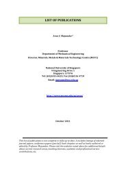
solution T. Indeed, T is equal to the flux limited value <strong>of</strong> T over the control volume faces (Figure<br />
1.1).<br />
(a) 2-D finite element<br />
(b) 1-D finite element showing CV's u,c,d and<br />
face f<br />
(c) Positioning <strong>of</strong> variables in and on the<br />
boundary <strong>of</strong> CVi<br />
FIGURE 1.1 Finite element and control volumes used to discretise the fluids equations. The<br />
central position <strong>of</strong> key solution variables are also indicated in (a).<br />
In order to obtain the final fluxes used at the Gaussian quadrature points on the control<br />
volume faces at element boundaries, these high-order fluxes are then subject to limiting. Figure<br />
1.1(a) shows a 2-D element with the positions <strong>of</strong> the key variables indicated. In 3-D the element<br />
variables are also centred on the nodes and elements; however the values <strong>of</strong> θ used for the<br />
transport terms are centred on the faces <strong>of</strong> the hexahedral elements.
FLUIDIZATION ENGINEERING: PRACTICE 9<br />
Suppose that each element i <strong>of</strong> the FE mesh has a control volume and a solution variable T<br />
associated with it. Then the FEM solution T is related to the CV solution T by Equation 1.9, in<br />
which N i is the finite element basis function associated with node i and M i is the finite volume<br />
basis function, which in this formulation is unity over element i and zero elsew<strong>here</strong>.<br />
N i T − TdV = 0, ∀i ∈ {1,2, … , N}<br />
V<br />
(1.9)<br />
In addition, the FEM representation <strong>of</strong> T is given by Equation 1.10 and Equation 1.11<br />
N<br />
T = N j T j<br />
j=1<br />
(1.10)<br />
BT = QT (1.11)<br />
with<br />
B = N i N j dV<br />
V<br />
and<br />
Q = N i M j dV<br />
V<br />
Thus, T = T 1 , T 2 , … , T N T , T = (T 1 , T 2 , … , T M ) T contain the unknown FE and CV values <strong>of</strong><br />
T, respectively. Both matrices B and Q have sparse structure.<br />
1.3.3 Extrema Detection<br />
In order to determine w<strong>here</strong> to apply first order instead <strong>of</strong> high-order fluxes, extrema must be<br />
detected. Thus, in order to ensure a smooth transition between the high and low order fluxes, the<br />
closeness to an extremum needs to be found. This is achieved using NVD approach (Leonard<br />
1988, Leonard and Mokhtari 1990) as follows.<br />
Transport is assumed to act from a cell, denoted as c, into a neighbouring cell, denoted as d.<br />
The corresponding solution variables are T c and T d and the far field upwind value is T u , Figure<br />
1.1 (b). Suppose T u , T c , T d are ordered consecutively and T f is the face value between CV's c and<br />
d. For a monotonic solution, Equation 1.12 describes the normalised high-order face value - T f .
FLUIDIZATION ENGINEERING: PRACTICE 10<br />
T f = T f − T u<br />
T d − T u<br />
∈ [0,1]<br />
(1.12)<br />
The normalised upwind face value, T c , is given by Equation 1.13.<br />
T c = T c − T u<br />
T d − T u<br />
(1.13)<br />
The idea is to obtain a linear combination T f <strong>of</strong> T f and T c such that T f equals T c when t<strong>here</strong><br />
exists a local extremum (i.e., T c ∉ [0,1] and the scheme becomes first order) and T f varies<br />
smoothly between this and the high order flux T f according to the curve shown on the NVD<br />
diagram (see Figure 1.2).<br />
FIGURE 1.2 The region occupied by T f using the NVD approach.<br />
T f is calculated from Equation 1.14 and the flux limited solution, T f , is calculated from<br />
Equation 1.15 with γ = 2.0.
FLUIDIZATION ENGINEERING: PRACTICE 11<br />
T f = T f − T u<br />
T d − T u<br />
(1.14)<br />
T f = minγT c, max0, T f , if T c ∈ (0,1)<br />
T c<br />
(1.15)<br />
Thus at an extremum, the first order non-oscillatory method will be applied. The curve<br />
T f = 2T c has been chosen as an upper bound on T f as this corresponds to a TVD condition in 1-<br />
D with equally spaced cells/elements (Hirsch 1990). One can use larger values <strong>of</strong> the gradient γ<br />
but convergence <strong>of</strong> the resulting non-linear iteration may be significantly slower. However, a<br />
larger gradient can help maintain sharper features in the solution as reported by (Jasak et al.<br />
1999). Indeed, they suggested the use <strong>of</strong> a gradient γ = 6.0 in Equation 1.15, and that the<br />
gradient should not be larger than 10 and not less than 2. Piperno and Depeyre (1998) explained<br />
some useful criteria for constructing limiting functions, and they used a maximum NVD curve<br />
with C 1 continuity, which is claimed to improve convergence. They also used a quotient <strong>of</strong><br />
gradients as opposed to the quotient <strong>of</strong> differences used <strong>here</strong> in Equations 1.12-1.14.<br />
The value <strong>of</strong> T u , in multi-dimensional problems, is not well defined and t<strong>here</strong>fore the<br />
minimum and maximum values <strong>of</strong> T in the CVs (t<strong>here</strong> are six CV's in 3-D and four CV's in 2-D,<br />
except if they are near a boundary) sharing a face with CV c, and CV c itself, are denoted by T min<br />
and T max , respectively. A normalised field variable is then obtained at the Gaussian integration<br />
point from the high-order T f via Equation 1.14 with the value <strong>of</strong> T u obtained from Equation 1.16.<br />
T u = T max, if T d ≤ T c<br />
(1.16)<br />
T min , if T d > T c<br />
This then allows the flux limiting, Equation 1.14 and 1.15 to be applied. For example, the<br />
scheme defined by Equation 1.17 introduces less dissipation than other bounded schemes.<br />
⎧ T f − T max<br />
, T<br />
T<br />
T f = d − T d ≤ T c<br />
max (1.17)<br />
⎨T f − T min<br />
, T<br />
⎩T d − T d > T c<br />
max<br />
The resulting flux limiting method will prevent any new extremum, however for a given<br />
direction a new extremum may appear along this direction resulting in oscillations in the
FLUIDIZATION ENGINEERING: PRACTICE 12<br />
solution. However, by choosing a control volume value (T u in Equations 1.12-1.16) in the<br />
upwind direction from face f and just upwind from CV c then this problem can be circumvented.<br />
1.3.4 Time Discretisation<br />
A new time discretisation scheme was developed <strong>here</strong> which smoothly switches from the<br />
second-order accurate Crank-Nicolson method (CNM) to the first-order backward Euler method.<br />
The CNM has the simplicity <strong>of</strong> a two-level time stepping method and is unconditionally stable<br />
(Ferziger and Peric 2002), i.e., it produces smooth solutions even when Δt is very large.<br />
However, the use <strong>of</strong> time steps <strong>of</strong> the order <strong>of</strong> the grid Courant number and above can result in<br />
oscillations and unphysical solutions (Hundsdorfer and Verwer 2007). Thus a parameter θ is<br />
introduced, in which θ = 0.5 corresponds to the CNM and θ=1.0 to the backward Euler method.<br />
Then using Equations 1.6 and 1.7, the time stepping for Equation 1.5 takes the form represented<br />
by Equation 1.18.<br />
M i T i n+1 − T i<br />
n<br />
Δt<br />
− s dV<br />
(1.18)<br />
= θa n+1 . nT n+1 + n. κ n+1 ∇T n+1 <br />
Γ CVi<br />
+ (1 − θ)a n . nT n + n. κ n ∇T n dΓ<br />
For each time step θ is calculated at each CV face based on the satisfaction <strong>of</strong> a TVD<br />
criterion. In 1-D, assuming the flux limiting values <strong>of</strong> the flux at the boundaries i − 1⁄ 2 and<br />
n<br />
n<br />
i + 1⁄ 2, Figure 1.1(c), are h i−1⁄<br />
2 and h i+1⁄<br />
2 at time level n, the time discretisation becomes one<br />
defined by Equation 1.19.<br />
Δx i T i n+1 n<br />
− T i<br />
<br />
Δt<br />
(1.19)<br />
= θ<br />
i−<br />
1<br />
2<br />
n+ 12 h 1 i−<br />
2<br />
n+1 n+ 12 n<br />
+ 1 − θ 1 h 1<br />
i− i−<br />
2<br />
2<br />
n+ 12 h 1 i+<br />
2<br />
− θ<br />
i+<br />
1<br />
2<br />
n+1 n+ 12 n<br />
− 1 − θ 1 h 1<br />
i+ i+<br />
2<br />
2<br />
with<br />
n<br />
h 1 i−<br />
2<br />
n T 1 i−<br />
2<br />
= a<br />
i−<br />
1<br />
2<br />
n + κ n<br />
1 i−<br />
2<br />
∂Tn<br />
∂x i− 1 2
FLUIDIZATION ENGINEERING: PRACTICE 13<br />
n+ 1 2<br />
In Equation (1.19), ∇x i is the width <strong>of</strong> the i CV and θ 1 is the value <strong>of</strong> θ associated with<br />
i+<br />
2<br />
face i + 1⁄ 2 and the time step from time level n to n + 1.<br />
The discretisation <strong>of</strong> the diffusion term, κ i−<br />
1<br />
n<br />
2<br />
∂Tn<br />
, is fully described in the next section.<br />
∂x i− 1 2<br />
n+1<br />
Thus, rearranging Equation 1.19 with θ ⁄ 2<br />
n+1<br />
i−1⁄<br />
2<br />
= 1 − θ ⁄ 2<br />
i−1⁄<br />
2<br />
, Equation 1.20 is obtained.<br />
⎛<br />
⎜ Δxi − Δt<br />
⎝<br />
−θ<br />
i− 1 2<br />
n+ 12 h 1 i−<br />
2<br />
n+1 + h n<br />
1 + θ<br />
i−<br />
= h n+1 1 − h 1<br />
i− i+<br />
2 2<br />
n+1<br />
2<br />
T i n+1 − T i<br />
n<br />
n+ 12<br />
i+ 1 −h 1 i+<br />
2 2<br />
n+1 + h n<br />
1<br />
i+<br />
2 ⎞ T n+1 n<br />
i − T i<br />
⎟ <br />
Δt<br />
⎠<br />
(1.20)<br />
Since the backward Euler method is TVD in the same way that first order upwind scheme is<br />
spatially, a positive definite mass matrix is a sufficient condition for this scheme (Equation 1.20)<br />
to be TVD (Hirsch 1990). Thus the diagonal mass matrix (in brackets – Equation 1.20) must be<br />
non-negative. After rearranging, this criterion is described in Equation 1.21 or Equation 1.22.<br />
Δt<br />
Δx i (T i n+1 − T i n ) θ i− 1 2<br />
n+ 12 n<br />
h 1 i−<br />
2<br />
− h<br />
i−<br />
1<br />
2<br />
n+1 − θ<br />
n+ 12 n<br />
i+ 1 h 1 i+<br />
2 2<br />
− h n+1 1 ≤ 1<br />
i+<br />
2<br />
(1.21)<br />
n+<br />
θ<br />
12 i− 1 p 1 i−<br />
2 2<br />
n+ 12 − θ<br />
n+ 12<br />
i+ 1 q 1 i+<br />
2 2<br />
n+ 12 ≤ 1<br />
(1.22)<br />
with<br />
n+ 12<br />
p 1 = <br />
i−<br />
2<br />
n<br />
h 1 i−<br />
2<br />
n+1<br />
− h 1 i−<br />
2<br />
T n+1 n<br />
i − T Δt<br />
i<br />
n+ 12 n n+1<br />
h 1 − h 1<br />
i+ i+<br />
2 2<br />
and q 1 = <br />
Δx i i− T n+1 n<br />
i − T Δt<br />
i<br />
Δx i<br />
2<br />
Equation 1.22 is satisfied if (Equation 1.23):
FLUIDIZATION ENGINEERING: PRACTICE 14<br />
n+<br />
θ<br />
12 i− 1 p 1 i−<br />
2 2<br />
n+ 12 ≤ 1 2 and − θ <br />
n+ 12<br />
i− 1 q 1 i−<br />
2 2<br />
n+ 12 ≥ 1 2<br />
(1.23)<br />
n+1<br />
Thus, in order to ensure that θ ⁄ 2<br />
n+1<br />
i−1⁄<br />
2<br />
= 1 − θ ⁄ 2<br />
i−1⁄<br />
2<br />
is close to 1 <br />
2<br />
, one may choose Equation<br />
1.24.<br />
⎧ ⎫<br />
n+ 12 ⎪ 1<br />
= max<br />
⎨2 , 1 − β min ⎛ 1<br />
⎜<br />
n+ 1 ,<br />
1 ⎞⎪<br />
<br />
n+ 1 ⎟<br />
2 2 ⎬<br />
⎪<br />
p 1 q 1 ⎪<br />
⎩<br />
⎝ i− i−<br />
2 2 ⎠⎭<br />
θ<br />
i−<br />
1<br />
2<br />
with β = 1 (1.24)<br />
2<br />
n<br />
n<br />
This method may be extended to multi-dimensions by replacing h i−1⁄<br />
2 with the integral <strong>of</strong> h f<br />
over face f and Δx i replaced by the volume L i (contribution from diagonal mass matrix) <strong>of</strong> the i-<br />
n+1<br />
th CV. Using similar arguments from the 1-D case, the following expression for θ ⁄ 2<br />
f<br />
<strong>of</strong> face f<br />
is obtained (Equation 1.25):<br />
n+ 12<br />
θ f<br />
= max 1 2 , 1 − β min 1 1<br />
, (1.25)<br />
n+ 1 n+ 1 2 2<br />
p f<br />
q f<br />
with<br />
p f<br />
n+ 12 =<br />
g f<br />
n+ 12 Δt<br />
(T c n+1 − T c n )L c<br />
, q f<br />
n+ 12 =<br />
g f<br />
n+ 12 Δt<br />
(T d n+1 − T c n )L d<br />
and g f<br />
n+ 12 =h f n -h f<br />
n+1<br />
(1.26)<br />
CV's c and d in Equations 1.25 and 1.26 refer to the two CV's that are adjacent to face f,<br />
(Figure 1.1(b)). Extensions <strong>of</strong> this method to differential equations with time-dependent terms<br />
like ∂ρT⁄ ∂t are realised by replacing T n j and T n+1 j by T n j ρ n j and T n+1 j ρ n+1 j , respectively for<br />
j = c and j = d.
FLUIDIZATION ENGINEERING: PRACTICE 15<br />
1.3.5 Diffusion Discretisation<br />
The high-resolution θ-method can also be used in the diffusion discretisation by adding to<br />
n+1<br />
g ⁄ 2<br />
f<br />
in Equation 1.26, the flux limited discretised contribution integrated along face i − 1⁄ 2.<br />
In 1-D, this might be represented by Equation 1.27, in which κ is the diffusion coefficient.<br />
n+ 12<br />
= h n<br />
1 − h 1<br />
i− i−<br />
g<br />
i−<br />
1<br />
2<br />
2<br />
n+1<br />
2<br />
n T 1 i−<br />
2<br />
= a 1<br />
n − a n+1 n+1<br />
1 T<br />
(1.27)<br />
1<br />
i− i− i−<br />
2<br />
2 2<br />
T n n<br />
i − T i−1<br />
+ κ <br />
1 2<br />
(Δx i−1 + Δx i ) − T i n+1 n+1<br />
− T i−1<br />
1 2<br />
(Δx i−1 + Δx i ) <br />
In multi-dimensions, this should be represented by Equations 1.28 and 1.29, in which n x is<br />
the normal to the control volume.<br />
g f<br />
n+ 12 = h f n − h f<br />
n+1<br />
(1.28)<br />
h f n = a n T n + κ ∂Tn<br />
∂n x<br />
dΓ<br />
Γ f<br />
(1.29)<br />
Now, if the underlying scheme that calculates ∂T n ⁄ ∂n x is non-oscillatory then the advectiondiffusion<br />
scheme will also be non-oscillatory. A simple example <strong>of</strong> this is given by Equation<br />
1.30, in which, as before, the subscripts denote cells that share face f (see Figure 1.1(b)), ∆x f<br />
represents the distance between the centres <strong>of</strong> the CV's c and d in the normal direction to face f.<br />
∂T n<br />
= ∂Tn = T c n n<br />
− T d (1.30)<br />
∂n x ∂n<br />
no f x ∆x<br />
f f
FLUIDIZATION ENGINEERING: PRACTICE 16<br />
Equation 1.30 also serves as a definition <strong>of</strong> ∂Tn<br />
∂n x<br />
<br />
no f<br />
. The accuracy <strong>of</strong> this approximation can<br />
be improved; however non-linearity must be used to ensure boundness <strong>of</strong> the scheme. Thus,<br />
suppose that the underlying non-oscillatory approximation to ∂T<br />
is ∂Tn<br />
, then any positive<br />
∂n x ∂n x no f<br />
multiple <strong>of</strong> this will result in a bounded scheme and as such the TVD condition is<br />
∂T n ∂T n<br />
≥ 0 (Hundsdorfer and Verwer 2007).<br />
∂n x<br />
f<br />
∂n x no f<br />
The scheme is bounded if the high order limited derivative ∂T n<br />
has the same sign as<br />
∂n x<br />
f<br />
∂Tn<br />
.<br />
∂n x no f<br />
However, to avoid difficulties with the non-linear convergence the derivative <strong>of</strong> ∂T n<br />
from the<br />
high order approximation ∂Tn<br />
is limited with (Equation 1.31)<br />
∂n x<br />
f<br />
∂n x<br />
f<br />
∂T n<br />
∂T n<br />
∂T n ∂T n<br />
s f = max γ<br />
∂n 2 s f , min s<br />
x ∂n f , γ<br />
f<br />
x ∂n 1 s f <br />
no f x ∂n<br />
f<br />
x no f<br />
with<br />
(1.31)<br />
γ 1 ≥ 1 ≥ γ 2 and s f = f(x) = 1, ∂T n<br />
≥ 0<br />
∂n x no f<br />
−1, otherwise<br />
In Equation 1.31, ∂Tn<br />
is the high order flux, which as with the advection scheme can be<br />
∂n x<br />
f<br />
obtained from any high order representation <strong>of</strong> T. The authors recommended the choice γ 1 = 2<br />
and γ 2 = 0.5. With a FEM discretisation, the derivative along a face f <strong>of</strong> the CV must be used.<br />
For derivatives along the boundaries <strong>of</strong> an element one may use a FE average <strong>of</strong> the<br />
derivative <strong>of</strong> the FEM representation <strong>of</strong> one element and the other sharing this face. This<br />
basically means that ∂Tn<br />
is calculated from Equation 1.32.<br />
∂n x<br />
f<br />
BT x n = PT n (1.32)<br />
with<br />
B = N i N j dV and P = N ix M j dV + n x N i M j dΓ<br />
Γ
FLUIDIZATION ENGINEERING: PRACTICE 17<br />
Robin boundary conditions can be applied in the surface integral above in matrix P which<br />
results in a source term. Alternatively, a Robin boundary condition <strong>of</strong> the form represented by<br />
Equation 1.33 can be applied directly in Equation 1.29.<br />
κ ∂Tn<br />
∂n = α(T − T 0)<br />
(1.33)<br />
In addition, a value for θ may be generated separately for the advection and diffusion terms;<br />
however the CNM is used more <strong>of</strong>ten in the approach described <strong>here</strong>.<br />
In the FEM discretisation using linear triangle, tetrahedra, rectangles or hexahedra, the<br />
diffusion term can also be bounded with restrictions on the distortion <strong>of</strong> the elements as reported<br />
by (Mizukami and Hughes 1985).<br />
1.3.6 Time Discretization <strong>of</strong> the Absorption Terms<br />
Now ignoring the advection and diffusion terms, Equation 1.5 becomes (Equation 1.34):<br />
∂<br />
∂t T(r, t) + σ(r, t)T(r, t) = S(r, t) (1.34)<br />
Discretising Equation (1.34) in time using the θ time stepping method yields (Equation 1.35):<br />
Tn+1 (r, t) − T n (r, t)<br />
+ θ n+12 (r)σ n+1 2(r)T n+1 (r)<br />
Δt<br />
(1.35)<br />
+ 1 − θ n+12 (r) σ n+1 2(r)T n (r, t)<br />
= θ n+12 (r)S n+1 (r, t) + 1 − θ n+12 (r) S n (r, t)<br />
Suppose S(r, t) is spatially and time independent then one may assume that both, the<br />
numerical and analytical solutions, are equal if an appropriate θ −n+1 2(r) is chosen as the one<br />
represented by Equation 1.36.
FLUIDIZATION ENGINEERING: PRACTICE 18<br />
θ n+12 (r) = max 1 2 , 2(r)Δt − 1.0 + e −Δtσn+1 2(r)<br />
σn+1 (1.36)<br />
σ n+1 2(r)Δt 1.0 + e −Δtσn+12(r) <br />
θ, defined in Equation 1.36, is extensively used in the applications described in section 6, in<br />
particular for λ (half-life) terms for delayed neutron precursors described in Equation 1.49. This<br />
condition also satisfies the TVD criteria for θ(r), which is described in Equation 1.37.<br />
θ n+12 1<br />
(r) ≥ 1 −<br />
Δtσ n+1 2(r)<br />
(1.37)<br />
This criterion is easily derived by ensuring that the scheme is a positive multiple <strong>of</strong> the<br />
backward Euler scheme. In fact, Equation 1.36 for θ n+1 2<br />
tends to Equation 1.37 from below.<br />
Equation 1.36 assumes that the material property σ(r) has been evaluated at time level n + 1⁄<br />
2<br />
and is thus constant throughout the time step. This time discretisation method that involves<br />
material properties was described in Pain et al. (2001e).<br />
1.3.7 Time-Limiting for the Non-Conservative Advection Equation<br />
The transport term is <strong>of</strong>ten expressed in non-conservative form, thus the internal energy equation<br />
may also be solved in such form. The reason for this is that the equations for inviscid single<br />
phase flow are not necessarily well-posed (Ferziger and Peric 2002, Hirsch 1990). One can<br />
obtain imaginary eigenvalues when the problem is posed as a Riemann problem and thus the<br />
solutions tend to diverge exponentially. A common solution is to solve for conservative<br />
variables, e.g., ρ, ρa, ρT (w<strong>here</strong> T, in this section, represents temperature), or to use a nonconservative<br />
form <strong>of</strong> the internal energy equation. This has the form given by Equation 1.38 or,<br />
in the more general multi-phase form, by Equation 1.39, in which k is the fluid phase, C pk is the<br />
specific heat capacity at constant pressure, α k is the volume fraction <strong>of</strong> phase k, T k is the<br />
temperature <strong>of</strong> phase k, S k the energy source or sink and a k is the velocity <strong>of</strong> phase k (Gomes et<br />
al. 2007).<br />
C p ρ ∂T<br />
∂t + a. ∇T + ∇. κ∇T = S (1.38)
FLUIDIZATION ENGINEERING: PRACTICE 19<br />
C pk α k ρ k ∂T k<br />
∂t + a k. ∇T k + ∇. κ k ∇T k = S k<br />
(1.39)<br />
In order to solve Equation 1.39, one may divide it by the heat capacity and integrate the<br />
resulting expression over the i th -CV, using Equation 1.40 and applying the Greens' theorem to<br />
the spatial derivative to obtain Equation 1.41.<br />
α k ρ k a k . ∇T k = ∇. α k ρ k a k T k − T k ∇. α k ρ k a k (1.40)<br />
M i α n+1 i ρ n+1 i T k n+1 n<br />
i<br />
− T ki<br />
dV<br />
Δt<br />
+ θ n+1 2a k n+1 . nα k n+1 ρ k n+1 T k n+1 − T k n+1 + κ k n. ∇T k n+1 <br />
Γ CVi<br />
(1.41)<br />
+ 1 − θ n+1 2 a k n . nα k n ρ k n T k n − T k n + κ k n. ∇T k n dΓ<br />
n+ 1 2<br />
s<br />
= M k<br />
i dV<br />
C pk<br />
This scheme (Equation 1.41) with θ n+1 2 = 1⁄ 2, is second-order accurate in time. However, in<br />
n+ 1 2<br />
order for the scheme to be non-oscillatory θ f<br />
will be defined as described in Equation 1.25<br />
n<br />
with h f defined by Equation 1.42.<br />
h n f = a k . nα k ρ k T n k + κ k n. ∇T n k dΓ<br />
Γ f<br />
(1.42)<br />
Here, the terms involving T n+1 i and T n i in Equation 1.41 have not been included in the<br />
derivation <strong>of</strong> θ as the authors want to achieve consistency with the multi-phase thermal energy<br />
n+1<br />
equation in conservative form. If these terms are included then the values <strong>of</strong> θ ⁄ 2<br />
f<br />
on the CV<br />
faces (in Equation 1.41) can be easily derived using a methodology similar to that used in the<br />
previous section. The variables α k , ρ k and T k are spatially limited individually as explained in<br />
the previous section to obtain a scheme that is bounded in all these variables. Additionally,
FLUIDIZATION ENGINEERING: PRACTICE 20<br />
appropriate boundary conditions (e.g., specified values resulting from incoming fluid) for each <strong>of</strong><br />
these variables are required and are allocated in the surface integrals <strong>of</strong> Equation 1.41 on the<br />
boundary <strong>of</strong> the domain.<br />
1.3.8 Mass Conservation and Volume Fraction Advection<br />
The multiphase continuity equation is given by Equation 1.43 and the corresponding discretised<br />
n+ 1 2<br />
continuity equation by Equation 1.44, in which s ck<br />
is the mass source/sink for fluid phase k.<br />
∂<br />
∂t (ρ kα k ) + ∇. α k ρ k a k = S ck<br />
(1.43)<br />
M i ρ n ki α k n+1 n<br />
i<br />
− α ki<br />
+ α n<br />
Δt<br />
ki ρ k n+1 n<br />
i<br />
− ρ ki<br />
dV<br />
Δt<br />
+ θ n+1 2a k n+1 . nα k n+1 ρ k n+1 α k<br />
n+1<br />
Γ CVi<br />
(1.44)<br />
+ 1 − θ n+1 2 a n k . nα n k ρ n k α n n+ 12<br />
k dΓ = M i s ck<br />
dV<br />
In order to enhance stability, the term involving ρ n+1 ki is treated implicitly in pressure (this<br />
may allow the Courant-Friedrichs-Lewy condition associated with acoustic waves to be<br />
exceeded) and absorbed into the discretised equation for pressure as described by Pain et al.<br />
(2001a, 2001b). The mass balance, Equation 1.43, and its discretised form, Equation 1.44, are<br />
embedded into the energy equations, Equation 1.39 and Equation 1.41, respectively.<br />
1.3.9 Mixed Formulation<br />
A transient mixed finite element formulation is used to discretise the transport equations.<br />
Additionally, the finite volume discretisation (Baliga and Patankar 1983) <strong>of</strong> both, the continuity<br />
equations and field variables, and a continuous Petrov-Galerkin (Johnson 1987) discretisation <strong>of</strong><br />
the momentum equations are employed. Within each time step the equations are iterated upon<br />
using a projection-based pressure determination method until all equations balance<br />
simultaneously, as reported by Pain et al. (2001a, 2001b). As a result the non-linear continuity<br />
equations are strictly satisfied, ensuring mass conservation. In the mixed formulation hexahedra<br />
‘brick’ elements in 3-D and rectangular elements in 2-D are employed which have a bi-linear
FLUIDIZATION ENGINEERING: PRACTICE 21<br />
variation <strong>of</strong> velocity and a piecewise constant variation <strong>of</strong> pressure, density and all other<br />
advected quantities. Thus, a single pressure is associated with each element and a velocity node<br />
(collocation point) is allocated at the corners <strong>of</strong> the element with C 0 variation <strong>of</strong> velocity<br />
between elements as shown in Figure 1.1(b).<br />
1.3.10 Solving the System <strong>of</strong> Linear Equations<br />
Similarly to several FEM formulations, in the FEM-HR scheme presented in this section, the<br />
equations involve diagonal dominant mass matrices which are well conditioned and have a<br />
condition number independent <strong>of</strong> the grid size (Pain et al. 2002). In contrast to first order<br />
discretisation methods, the FEM-HR equations have coupling in all directions.<br />
The FEM-HR method used <strong>here</strong> is obtained by making each element a CV and using a<br />
mapping between the CV and the FEM solution, which is used as the high order flux along the<br />
CV faces (Voller 2009). The FEM-HR method requires the inverse <strong>of</strong> the consistent mass matrix<br />
in order to calculate incoming CV fluxes accurately (this inverse is a full matrix). The FEM-HR<br />
method was generalised with a bijective mapping between the FEM and CV (Pain et al. 2006,<br />
2001b). The discontinuous FEM-HR method also uses consistent mass matrices, Equation 1.11,<br />
but these are local to an element so they are more manageable and can be treated implicitly.<br />
T<strong>here</strong> are a number <strong>of</strong> options available for solving the non-linear FEM-HR equations. One can<br />
linearise the global equation set, and the down-stream element coupling is treated implicitly or<br />
explicitly. However, including the downstream coupling may result in poorer conditioned<br />
matrices from the discretisation. Then a global set <strong>of</strong> linear equations would be solved for each<br />
non-linear iteration by, for example, using the symmetric successive over-relaxation (SSOR)<br />
preconditioning method for the Generalised Minimal Residual Method (GMRES) (Saad and<br />
Schultz, 1986). Alternatively, one can sweep through each CV, resolving all the non-linear<br />
equations local to each CV with a suitable linearization procedure.<br />
The global or local to an element linearization can be achieved using the Newton-Raphson<br />
method; although this has quadratic convergence properties it is prone to failure when one does<br />
not have a good initial guess. The most robust method reported for other flux limiting methods is<br />
to linearise the first-order equations (Darwish 1993). This involves solving a matrix equation<br />
with a matrix obtained from the underlying first-order spatial discretisation and the deviation <strong>of</strong><br />
the high-order scheme from this, which is treated explicitly as a source term. The main<br />
advantages <strong>of</strong> this method are that the resulting matrix is well-conditioned and the non-linear<br />
convergence to a solution is usually monotonic, due to the dissipative characteristics <strong>of</strong> the firstorder<br />
scheme.<br />
1.4 Neutron Radiation Transport<br />
In this section the deterministic neutral particle balance equations are presented. The first order<br />
conservation balance is first introduced. Following this the second order even-parity form is<br />
derived. Finally a commonly used approximation called diffusion theory is outlined. Notational<br />
bias is towards that which prevails in the neutron transport literature.
FLUIDIZATION ENGINEERING: PRACTICE 22<br />
1.4.1 Deterministic Neutral Particle Balance<br />
The simulation <strong>of</strong> neutral particles through a domain has many applications including the<br />
transport <strong>of</strong> photons through clouds, nuclear well-logging, nuclear reactors and nuclear criticality<br />
facilities. The transport <strong>of</strong> neutral particles is mathematically described via the linear neutral<br />
particle Boltzmann Transport equation, an adaptation <strong>of</strong> the Boltzmann Transport equation<br />
formulated for gases. The Neutral Particle Transport equation, which describes the evolution <strong>of</strong> a<br />
neutral particle density field in full phase space (Cartesian space, angle, energy, time), is given<br />
by Equation 1.45, in which ψ(r, Ω, E, t) is the angular particle flux at phase point p (being<br />
spatial coordinate r, in direction Ω , at energy E and at time t). v(E) is the particle velocity<br />
associated with energy E; S(r, Ω, E, t)is the source term and H is the scattering removal<br />
operator, which is defined by Equation 1.46.<br />
1 ∂<br />
v(E) ∂t ψ(r, Ω, E, t) + Ω. ∇ψ(r, Ω, E, t) + Hψ(r, Ω, E, t) = S(r, Ω, E, t) (1.45)<br />
Hψ(r, Ω, E, t) = Σ t (r, E, t)ψ(r, E, Ω, t)<br />
∞<br />
− dE ′<br />
0<br />
dΩ ′ Σ s (r, E ′ → E, Ω ′ → Ω, t)ψ(r, E, Ω, t)<br />
4π<br />
(1.46)<br />
In Equation 1.46, Σ t (r, E, t) is the total (or extinction) cross-section and Σ s (r, E ′ → E, Ω ′ →<br />
Ω, t) is the scattering cross-section from energy E’ to E and from angle Ω′to Ω.<br />
If the scattering is assumed to be independent <strong>of</strong> the incident angle, such that only the change<br />
in angle matters, the scattering removal operator can be written explicitly by Equation 1.47, in<br />
which P l and Σ sl are the Legendre polynomials and the scattering moments, respectively.<br />
∞<br />
Hψ(r, Ω, E, t) = 2l + 1 ∞<br />
4π<br />
dEΣ t<br />
0<br />
t=0<br />
− Σ sl (r, E ′ → E, t) dΩ′P l (Ω. Ω′)ψ(r, Ω, E, t)<br />
4π<br />
(1.47)<br />
The angular particle flux is related to the angular particle density, N(r, Ω, E, t), via<br />
ψ(r, Ω, E, t) = vN(r, Ω, E, t) in which v is the speed <strong>of</strong> the neutral particles.
FLUIDIZATION ENGINEERING: PRACTICE 23<br />
By considering a small control volume dp in the phase space given by<br />
dp = dVdΩdE in which dV is a control volume in real space R 3 , then ψ(r, Ω, E, t)dp represents<br />
the angular particle flux density in dV about r, with direction dΩ about Ω and energy dE about E<br />
occurring at time t.<br />
The first term on the left-hand-side <strong>of</strong> Equation 1.45 represents the rate <strong>of</strong> change <strong>of</strong> the<br />
angular particle density at every point within the phase space. The second term on the left given<br />
by Ω. Ω. ∇ψ(r, Ω, E, t), called the streaming term, represents the net rate at which the angular<br />
particle density spatially propagates away from every point in the phase space. The scattering<br />
removal operator, H, represents the rate at which the angular particle density is removed from<br />
phase point p via absorption with the host medium present in the domain, minus the rate at which<br />
the angular particle density is scattered from phase point p’ to phase point p, due to interactions<br />
again with the host medium. Note that p’ could be a phase point with a different energy or a<br />
different direction or both. The term ∑ t (r, E, t) is the total (scattering and absorption)<br />
macroscopic cross-section (with units cm -1 ), between the host medium and the angular particle<br />
density at phase point p. The term ∑ s (r, E ′ → E, Ω ′ → Ω, t) is the double differential<br />
macroscopic scattering cross-section representing the probability that the angular particle density<br />
with energy E’ and direction Ω′ will scatter with the host medium into energy dE about E and<br />
direction dΩ about Ω, for all points in the phase space. Note that the time dependence <strong>of</strong> the<br />
macroscopic cross-sections arises due to their dependence on the number density <strong>of</strong> the host<br />
medium, which may change with time. The source term S(r, Ω, E, t) represents all sources <strong>of</strong><br />
neutral particles, such as prescribed and fission. In deriving Equation 1.45 t<strong>here</strong> are some<br />
implicit assumptions made. These include assuming point particles, instantaneous reactions,<br />
external forces do not affect the motion <strong>of</strong> the neutral particles and no particle reactions occur.<br />
The latter assumption is valid provided the number density <strong>of</strong> the host medium is far greater than<br />
the number density <strong>of</strong> the neutral particles, which is <strong>of</strong>ten the case.<br />
For neutrons within a nuclear reactor the source term is given by Equation 1.48, in which the<br />
first term on the right represents external neutron sources and the other two terms are the prompt<br />
and delayed fission neutrons respectively.<br />
S(r, Ω, E, t) = S ext + 1 − β ∞<br />
eff<br />
χ<br />
4π p dE′ dΩ′ν(E′)Σ f (r, E′, t) ψ(r, Ω′, E′, t)<br />
0 4π<br />
+ λ d χ d k C k (r, t)<br />
k<br />
(1.48)<br />
In Equation 1.48, β eff represents the fraction <strong>of</strong> neutrons that are delayed, χ p is the prompt<br />
fission spectrum, χ p<br />
d<br />
is the delayed fission spectrum from delayed precursor group k, C k is the<br />
delayed neutron precursor concentration for delayed group k, λ k is the decay constant for<br />
delayed group k, ν is the number <strong>of</strong> neutrons emitted per fission event and Σ f (r, E′, t) is the<br />
macroscopic fission cross-section. The delayed neutron precursor groups represent the fission<br />
products that beta decay to a daughter that then spontaneously decay via neutron emission. Each<br />
delayed group has a characteristic decay constant and fission yield. The delayed neutrons created<br />
in these processes are vital for control <strong>of</strong> the nuclear reaction. The governing equation for the k th
FLUIDIZATION ENGINEERING: PRACTICE 24<br />
delayed neutron precursor group is given by Equation 1.49, in which u is the velocity <strong>of</strong> the host<br />
medium, β d is the fraction <strong>of</strong> delayed neutron precursor group k produced via fission and<br />
φ(r, E′, t) is the scalar flux. This scalar flux is given by φ(r, E′, t) = ∫ ψ(r, Ω ′ , E ′ , t)dΩ.<br />
4π<br />
∂<br />
∂t C k(r, t) + u. ∇C k = −λ k C k (r, t) + β k ν(E′)Σ f (r, E′, t)φ(r, E′, t)<br />
0<br />
∞<br />
(1.49)<br />
The Neutral Particle Transport Equation, Equation 1.45, is a first order hyperbolic integrodifferential<br />
equation that can in theory provide an exact description <strong>of</strong> the time dependent neutral<br />
particle density distribution, provided the assumptions <strong>of</strong> the derivation are based on hold for the<br />
particular problem in question. In practice an exact analytical transport solution is only possible<br />
for certain idealised problems which are based on further assumptions. Equation 1.45 is<br />
extremely hard to solve for realistic problems due to the angular flux depending on seven<br />
variables (x, y, z, θ, φ, E, t) and due to the complex dependence <strong>of</strong> the macroscopic crosssections<br />
on position and energy. The numerical solution can be obtained by discretising each<br />
variable <strong>of</strong> the angular flux using a variety <strong>of</strong> schemes. These could be applied directly to the<br />
first order neutron transport equation or to alternative variations <strong>of</strong> it, such as the second order<br />
even parity neutron transport equation.<br />
1.4.2 Boundary Conditions<br />
As with all differential equations to obtain a particular solution, boundary and initial conditions<br />
are necessary. For the initial condition, (r, Ω, E, t) = ψ 0 (r, Ω, E, t).<br />
The general albedo boundary condition is given by Equation 1.50, in which w<strong>here</strong> Γ V<br />
represents the boundary <strong>of</strong> the domain V, α is the prescribed albedo coefficient and Ω is the<br />
reflected angle corresponding to the incident angle Ω′.<br />
ψ(r, Ω, E, t) = α(r, Ω, E, t)ψ(r, Ω′, E, t) for r ∈ Γ V (1.50)<br />
1.4.3 The Second Order Even Parity Neutron Transport Equation<br />
In a previous section, the first order neutron transport equation was introduced. In this section,<br />
the formulation to the equivalent even and odd parity neutron transport equations are outlined,<br />
then the second order even parity neutron transport equation is formed.<br />
The first step is to separate the angular flux into even and odd parts via the Vladimirov<br />
transformation (Vladimirov 1963) given by Equations 1.51, 1.52 and 1.53.
FLUIDIZATION ENGINEERING: PRACTICE 25<br />
ψ even (r, Ω, E, t) = 1 2 [ψ(r, Ω, E, t) + ψ(r, −Ω, E, t)] (1.51)<br />
ψ odd (r, Ω, E, t) = 1 2 [ψ(r, Ω, E, t) − ψ(r, −Ω, E, t)] (1.52)<br />
ψ(r, Ω, E, t) = ψ even (r, Ω, E, t) + ψ odd (r, Ω, E, t) (1.53)<br />
By substitution <strong>of</strong> Ω → −Ω into Equation 1.45, it results in Equation 1.54.<br />
1 ∂<br />
v(E) ∂t ψ(r, −Ω, E, t) − Ω. ∇ψ(r, −Ω, E, t) + Hψ(r, −Ω, E, t) = S(r, −Ω, E, t) (1.54)<br />
As it can be noticed, a negative sign will appear in the double differential scattering crosssection<br />
relating to the angle difference variable. It can be shown that by adding Equation 1.45 to<br />
Equation 1.54 and by subtracting Equation 1.54 from Equation 1.45 results in the coupled evenodd<br />
parity neutron transport equations (Equations 1.55 and 1.56).<br />
1 ∂<br />
v ∂t ψeven + Ω. ∇ψ odd + Cψ even = S even<br />
(1.55)<br />
1 ∂<br />
v ∂t ψodd + Ω. ∇ψ even + G −1 ψ odd = S odd<br />
(1.56)<br />
In Equations 1.55 and 1.56, the source has been transformed in to even and odd parity<br />
components and the operators C and G -1 are given by Equation 1.57 and Equation 1.58, in which<br />
the macroscopic scattering cross-section has also been decomposed into even and odd parity<br />
components.<br />
∞<br />
Cψ even = Σ t (r, E, t)ψ even − dE′<br />
0<br />
∞<br />
G −1 ψ odd = Σ t (r, E, t)ψ odd − dE′<br />
0<br />
dΩ′ Σ even s (r, E ′ → E, Ω′ → Ω, t)ψ even<br />
4π<br />
dΩ′ Σ odd s (r, E ′ → E, Ω′ → Ω, t)ψ odd<br />
4π<br />
(1.57)<br />
(1.58)
FLUIDIZATION ENGINEERING: PRACTICE 26<br />
By a simple substitution for the odd parity angular flux, the steady state second order<br />
transport equation for the even parity angular flux is given by Equation 1.59.<br />
−Ω. ∇[GΩ. ∇ψ even (r, Ω, E, t)] + Cψ even (r, Ω, E, t)<br />
= S even (r, Ω, E, t) − Ω. ∇G odd (r, Ω, E, t)<br />
(1.59)<br />
By solving for the even parity flux the odd parity angular flux can be ascertained. The even<br />
and odd angular flux components have physical significance which can be seen by integrating<br />
them over all directions (Equation 1.60).<br />
⎧ φ(r, E, t) = ψ(r, Ω, E, t) = ψ even (r, Ω, E, t)<br />
4π<br />
4π<br />
⎨J(r, E, t) = Ω. ψ(r, Ω, E, t) = Ω. ψ odd (r, Ω, E, t)<br />
⎩<br />
4π<br />
4π<br />
(1.60)<br />
In Equation 1.60, φ(r, E, t) is the scalar flux and J(r, E, t) is the neutral particle current.<br />
1.4.4 Diffusion Theory Derivation<br />
Often complex transient multi-physics modelling applied to applications <strong>of</strong> engineering interest<br />
requires simplification <strong>of</strong> the neutral particle model component. One common simplified model<br />
is called diffusion theory. Diffusion theory is obtained from the Even Parity transport equation<br />
using a linear anisotropic approximation <strong>of</strong> the angular particle flux. This is rigorously derived<br />
via substitution <strong>of</strong> the necessary spherical harmonic functions.<br />
A simplified derivation based on physical arguments is more <strong>of</strong>ten used to introduce the<br />
method. Assuming isotropic scattering and sources, integrating Equation 1 over all angles gives<br />
(Equation 1.61):<br />
1 ∂<br />
v(E) ∂t φ(r, E, t) + ∇. J(r, E, t) + Hφ(r, E, t) = S(r, E, t) (1.61)<br />
In Equation 1.61, φ(r, E, t) is the scalar particle flux density at position r, with energy E at<br />
time t, J(r, E, t) is the particle current density, H is now the diffusion theory scattering removal
FLUIDIZATION ENGINEERING: PRACTICE 27<br />
operator and S(r, E, t) is the particle flux source that can include prescribed, production and<br />
delayed. The scalar particle flux density is given by Equation 1.62 and the particle current<br />
density by Equation 1.63.<br />
φ(r, E, t) = ψ(r, Ω, E, t)dΩ<br />
4π<br />
(1.62)<br />
J(r, E, t) = j(r, Ω, E, t)dΩ<br />
4π<br />
= Ωψ(r, Ω, E, t)dΩ<br />
4π<br />
(1.63)<br />
To obtain the neutron diffusion equation a relation between the two unknowns, the particle<br />
flux density,φ(r, E, t), and the particle current density, J(r, E, t), given by Equation 1.64, is<br />
implemented as a constitutive closure law. This type <strong>of</strong> diffusion approximation implies that<br />
particles will diffuse from high density regions to lower density regions.<br />
J(r, E, t) ≅ −D(r, E, t)∇φ(r, E, t) (1.64)<br />
The diffusion tensor D(r, E, t) can be obtained via a rigorous derivation <strong>of</strong> diffusion theory<br />
from the Boltzmann equation via the Even Parity formulation. This calculation would give<br />
(Equation 1.65):<br />
D(r, E, t) =<br />
1<br />
3Σ tr (r, E, t) I (1.65)<br />
In Equation 1.65, Σ tr (r, E, t) and I are the transport macroscopic cross-section and the<br />
diagonal identity tensor, respectively. The diffusion theory flux and current are related to the<br />
transport angular flux via the approximation described in Equation 1.66.<br />
ψ(r, Ω, E, t) ≅ 1<br />
4π [φ(r, E, t) + 3Ω. J(r, E, t)] (1.66)
FLUIDIZATION ENGINEERING: PRACTICE 28<br />
This states the assumption that the angular flux can be approximated as being linear<br />
anisotropic in angle. If the medium through which particles propagate is anisotropic the<br />
diffusivity tensor in 3 dimensions would be given by Equation 1.67.<br />
1<br />
0 0<br />
⎛<br />
3Σ trxx<br />
(r, E, t)<br />
⎞<br />
⎜<br />
1<br />
⎟<br />
D(r, E, t) = ⎜<br />
0<br />
0<br />
3Σ tryy<br />
(r, E, t)<br />
⎟<br />
⎜<br />
⎟<br />
1<br />
0 0<br />
⎝<br />
3Σ trzz<br />
(r, E, t)⎠<br />
(1.67)<br />
This anisotropic nature can arise following flux weighted homogenisation within a nuclear<br />
reactor context. Permitting different diffusivity values on the diagonal terms <strong>of</strong> this tensor allows<br />
regions within the model to only have particle propagation in one <strong>of</strong> the coordinate axis<br />
directions. In order to allow particle propagation only in a direction not aligned with a coordinate<br />
axis the diffusivity tensor is rotated such that (see Equation 1.68):<br />
T<br />
D(r, E, t) ⟶ R x,y,z (r, E, t)D(r, E, t)R x,y,z (r, E, t) (1.68)<br />
In Equation 1.68, R x,y,z (r, E, t) is a rotation tensor field about one <strong>of</strong> the coordinate axis.<br />
Through successive application <strong>of</strong> rotation matrices the diagonal input diffusivity tensor can be<br />
adjusted as required.<br />
1.4.5 Boundary Conditions<br />
The partial currents into and out <strong>of</strong> the domain across a surface are given by Equation 1.69.<br />
j in (r, E, t) = 1<br />
<br />
4 φ(r, E, t) + 1 n. D(r, E, t)∇φ(r, E, t)<br />
2 (1.69)<br />
j out (r, E, t) = 1 4 φ(r, E, t) − 1 2 n. D(r, E, t)∇φ(r, E, t)<br />
The net current across a boundary is thus given by Equation 1.70.
FLUIDIZATION ENGINEERING: PRACTICE 29<br />
J net (r, E, t) = j out (r, E, t) − j in (r, E, t) = −n. D(r, E, t)∇φ(r, E, t) (1.70)<br />
A reflective boundary condition requires all odd moments <strong>of</strong> the angular flux expansion to<br />
vanish. For diffusion theory this implies that the net current across the surface be zero and is<br />
expressed by Equation 1.71.<br />
n. J(r, E, t) = −n. D(r, E, t)∇φ(r, E, t) = 0 (1.71)<br />
A known net current across the domain surface is expressed by Equation 1.72, in which<br />
C 0 (r, E, t) is a prescribed surface field for each energy E.<br />
n. J(r, E, t) = −n. D(r, E, t)∇φ(r, E, t) = C 0 (r, E, t) (1.72)<br />
A vacuum boundary condition requires that the partial current into the domain across a<br />
surface be zero. This implies on vacuum boundary condition surfaces that Equation 1.73 applies.<br />
1<br />
2 φ(r, E, t) + n. D(r, E, t)∇φ(r, E, t) = 0 (1.73)<br />
A known and non-zero partial current into the domain is also a valid boundary condition. An<br />
albedo boundary condition representing a partial reflection is quantified by the albedo coefficient<br />
given by Equation 1.74.<br />
α(r, E, t) = j in(r, E, t)<br />
j out (r, E, t)<br />
(1.74)<br />
In Equation 1.74, when α has value 0 the vacuum boundary condition is implied and when α<br />
has value 1 the reflective boundary condition is implied. Substitution <strong>of</strong> the partial currents,<br />
Equation 1.69, into the albedo coefficient definition, Equation 1.74, with some rearrangement<br />
results in the albedo boundary condition given by Equation 1.75.
FLUIDIZATION ENGINEERING: PRACTICE 30<br />
1 + α(r, E, t)<br />
1<br />
2 1 − α(r, E, t) φ(r, E, t) + n. D(r, E, t)∇φ(r, E, t) = 0 (1.75)<br />
The reflective, Equation 1.71, and prescribed net current, Equation 1.72, boundary conditions<br />
are also referred to as Neumann boundary conditions. The vacuum, Equation 1.73, prescribed<br />
inward partial current, Equation 1.73, and albedo, Equation 1.75, boundary conditions are also<br />
referred to as Robin boundary conditions. The general Robin boundary condition applied to a<br />
scalar field is given by Equation 1.76, in which C 0 (r, E, t) and C 1 (r, E, t) are the zero and first<br />
order coefficients surface field at each energy E, respectively.<br />
n. D(r, E, t)∇φ(r, E, t) + C 1 (r, E, t)φ(r, E, t) = C 0 (r, E, t) (1.76)<br />
A further mathematically possible boundary condition is the Dirichlet type. The Dirichlet<br />
boundary condition sets the value <strong>of</strong> the flux at the domain surface. It is however not strictly<br />
correct within the multi-group diffusion physical model and is only used as an approximation to<br />
a vacuum boundary condition in special cases.<br />
1.4.6 Eigenvalue – Gauge <strong>of</strong> Criticality<br />
The k eff eigenvalue problem is realised by dividing the fission source term in the transport<br />
equation, Equation 1.45, by the eigenvalue, k eff , and ignoring the terms relating to the time<br />
dependence, i.e., β eff = 0. The eigenvalue (k eff , section 1.6.2) is related to the effective<br />
multiplication factor <strong>of</strong> neutrons, as described in Duderstadt and Hamilton (1976). The<br />
eigenvalue problem is then solved to help gauge the magnitude <strong>of</strong> the nuclear reactivity <strong>of</strong> the<br />
system. The eigenvalue is sometimes presented in terms <strong>of</strong> multiples (dollars, $) or the effective<br />
delayed neutron fraction, β eff .<br />
1.5 Coupling Methods<br />
1.5.1 Introduction<br />
For the safe operation <strong>of</strong> a nuclear facility it is necessary to know the operational boundary<br />
conditions within which the system can operate without any unwanted consequences. An<br />
example <strong>of</strong> this is the release <strong>of</strong> radioactive material to the surrounding environment. To obtain<br />
these conditions a detailed and realistic understanding <strong>of</strong> the physics occurring within the facility<br />
is required. This understanding requires empirical experiment and theoretical solutions <strong>of</strong> the<br />
relevant physical equations. Because <strong>of</strong> the large number <strong>of</strong> calculations needed for a theoretical
FLUIDIZATION ENGINEERING: PRACTICE 31<br />
solution within the complex domain <strong>of</strong> a nuclear facility, computational numerical simulation is<br />
widely utilised. Due to the complexity <strong>of</strong> a nuclear facility and the relevant equations, it was<br />
customary in the past to simplify the geometry (for example by homogenising) and to<br />
approximate the equations (for example by reducing the number <strong>of</strong> dimensions) to obtain results.<br />
T<strong>here</strong>fore only conservative safety limits could be obtained in this way implying the resulting<br />
design may not be the optimal with respect to many factors such as economics or safety.<br />
Contained within a nuclear facility t<strong>here</strong> are many physical processes occurring that can be<br />
broken down into distinct topics for analysis. These include Neutron Kinetics (NK), Thermal-<br />
Hydraulics (T-H) and Structural Mechanics (such as Fuel Performance). In the past when limited<br />
computational power was available, these topics w<strong>here</strong> evaluated to obtain theoretical solutions<br />
independently <strong>of</strong> each other, or with extremely simplified models <strong>of</strong> one or more <strong>of</strong> the other<br />
areas. For example, with regard to a nuclear reactor, a detailed T-H calculation would have<br />
performed with an assumed steady state core power pr<strong>of</strong>ile or a zero dimensional NK model. In<br />
recent years with the continuing advancement in computer technology and numerical algorithms<br />
it has become possible to model more complexity allowing a more in depth understanding <strong>of</strong><br />
nuclear reactor dynamics. These programs (or codes) are classed as Best Estimate (BE), in<br />
contrast to previous Conservative codes. Initially these BE codes (within their own areas) were<br />
developed independently <strong>of</strong> the other areas, or coupled to a conservative code <strong>of</strong> another area. It<br />
has now become desirable to couple together BE codes from each different topic to understand<br />
complex feedback occurring between each during a transient scenario. For accident analysis it<br />
has become obligatory to couple together BE NK and T-H codes to ascertain a better estimate<br />
solution <strong>of</strong> maximum power and temperature limits <strong>of</strong> a reactor design for all realistically<br />
possible scenarios (Structural Mechanic codes are not discussed as a part <strong>of</strong> this research). In the<br />
future the coupling will be extended to include other modules such as structural, fuel<br />
management and depletion codes.<br />
In the following section the coupled radiation transport multiphase fluid dynamic FETCH<br />
model is described.<br />
1.5.2 Finite Element Transient Criticality Model<br />
FETCH (Pain et al. 2001c, AMCG 2011) is a coupled deterministic radiation transport<br />
multiphase fluid dynamic code implemented within the finite element framework. FEM has great<br />
geometrical flexibility allowing the possibility <strong>of</strong> complex domains (such as nuclear reactor<br />
cores) to be modelled in similar detail compared with stochastic Monte Carlo methods (with<br />
enough computational resources) in certain instances. FETCH consists <strong>of</strong> four modules; the preprocessor<br />
mesh generator GEM, a radiation transport module, a multiphase fluids module and an<br />
interface module.<br />
The radiation transport module, called Even Parity Neutral Particle Transport (see section 1.4,<br />
de Oliveira et al. 1998, EVENT in AMCG 2011), solves the radiation transport equation in full<br />
phase space based on a second order even-parity variational finite element formulation, using<br />
spherical harmonics to discretise the angular dependence <strong>of</strong> the neutron flux (or a photon flux).<br />
The energy dependence is modelled via the common multi-group method forming a set <strong>of</strong><br />
discrete energy transport equations that are coupled through the intergroup (up-scatter as well as
FLUIDIZATION ENGINEERING: PRACTICE 32<br />
down scatter) scattering source terms. The neutronics module can be applied to transient<br />
simulations (with non-linear feedback from the fluids module) and also to static simulations to<br />
obtain the multiplication factor (k-effective) for the input domain.<br />
The multiphase fluid dynamic module (see sections 1.2 and 1.3, FLUIDITY in AMCG 2011)<br />
solves the non-linear momentum transport and continuity equations, as well as advectiondiffusion<br />
equations for any other variable fields as desired (for example temperature or tracers).<br />
FLUIDITY (AMCG 2011) uses a variety <strong>of</strong> discretisation methods such as standard Galerkin,<br />
Petrov-Galerkin and has the capability to perform Large Eddy Simulation (LES). The coupling<br />
between each phase is through the use <strong>of</strong> relevant empirical heat and momentum transfer<br />
correlations that are dependent on the physical problem being simulated. Within each <strong>of</strong> the<br />
neutronic and fluid dynamic modules a choice <strong>of</strong> finite elements is available, as well as the<br />
ability to simulate in Cartesian or cylindrical coordinates. Implemented adaptive time stepping<br />
ensures the relevant physics is captured while maximising computational simulation speed.<br />
The interface module passes updated information like temperature fields and sources (due to<br />
fission) between the other two modules within each time step. The neutronics module uses the<br />
updated fields (which can include changes in material composition) to interpolate for new crosssections<br />
within each finite element. The fission source generated in the neutronics module<br />
produces a heat source for the fluids module introducing a feedback into the simulation. The<br />
cross-sections are interpolated between a pre-determined data set generated using the reactor<br />
physics WIMS9 code (WIMS - Winfrith Improved Multigroup Scheme) <strong>of</strong> Serco Assurance<br />
(Martindill 2004). The WIMS9 code generates macroscopic group cross-sections using a variety<br />
<strong>of</strong> techniques such as collision probability methods, and then collapses them to the desired<br />
number <strong>of</strong> energy groups (usually 6 groups). A characteristic geometry is used within the<br />
WIMS9 input file and resonance self-shielding effects are accounted for, as well as temperature<br />
and density changes, in the generation <strong>of</strong> group constants. Within the FETCH model the crosssections<br />
are taken as piece-wise constant over each element <strong>of</strong> the domain and interpolated<br />
between linearly.<br />
Each module reduces the relevant partial differential equations to a set <strong>of</strong> simultaneous linear<br />
equations, the number <strong>of</strong> which depends on the number <strong>of</strong> finite elements and the order <strong>of</strong> the<br />
basis function approximation used. These are then solved for using various iterative techniques<br />
such as the pre-conditioned conjugate gradient method and GMRES.<br />
The coupled FETCH code has been applied to the modelling <strong>of</strong> criticality accidents in fissile<br />
solutions (Pain et al. 2001c, d, e). Results were validated against actual experimental data and<br />
compared to other criticality codes. Due to showing good agreement with available data, FETCH<br />
has also been applied to scenarios w<strong>here</strong> t<strong>here</strong> exists limited experimental knowledge. This<br />
includes modelling criticality in plutonium solutions (Pain et al. 2001c) and a novel fluidized<br />
HTGR (Miles et al. 2010b, Pain et al. 2005). FETCH is now being applied to a variety or nuclear<br />
reactors. The radiation transport module EVENT has also been validated for various benchmark<br />
simulations (de Oliveira et al. 2001, Ziver et al. 2005) and applied to a variety <strong>of</strong> scenarios such<br />
as nuclear reactors, atmospheric clouds and nuclear well-logging. The Computational Fluid<br />
Dynamics (CFD) module FLUIDITY has been applied to model fluidised beds, oceans,<br />
atmospheric pollution and more recently asteroid crater impacts.
FLUIDIZATION ENGINEERING: PRACTICE 33<br />
The flow structure <strong>of</strong> FETCH is now illustrated to show how non-linear feedback mechanisms<br />
can be captured, an essential condition for modelling nuclear reactor transients. Initially a set <strong>of</strong><br />
macroscopic group cross-sections are generated (typically using a reactor physics code) for the<br />
desired range <strong>of</strong> temperature and burn-up for each material. Then within each adaptive time step<br />
the following iterative algorithm occurs until the specified convergence is met:<br />
1. Using the beginning <strong>of</strong> time step temperature and material distribution, a cross-section is<br />
obtained for each element in the mesh via interpolating the predetermined different<br />
temperature and burn-up cross-sections<br />
2. The Neutron Transport equation is then solved for each energy group to obtain the angular<br />
flux for the entire domain<br />
3. The delayed neutron precursor concentration equations are then solved for each group<br />
(usually six) using the scalar flux for calculating the source term;<br />
4. The temperature equations (one for each phase if multiphase) are then solved with the<br />
scalar flux providing the fission heat source<br />
5. Finally the Navier-Stokes equations (momentum and continuity for each phase) are solved<br />
subject to given boundary and initial conditions, with the temperature field providing a<br />
buoyancy force in the fluid phase<br />
This allows temperature, density and material changes to be captured in determining the<br />
neutron distribution across the domain, which is the fundamental requirement needed for nuclear<br />
reactor modelling. During a transient simulation this nonlinear feedback (characterised by<br />
reactivity coefficients) will allow a detailed determination <strong>of</strong> the coupled multi-physics processes<br />
that occur in reality, accurately describing the sequence <strong>of</strong> events that will unfold in BE<br />
approach.<br />
1.6 Applications<br />
A number <strong>of</strong> nuclear reactors have been developed for possible deployment in the next three<br />
decades. They generally operate at a higher temperature than existing reactors, enabling a<br />
thermodynamic cycle <strong>of</strong> higher efficiency. The PBR (see section 1.6.1) is a HTGR. This is<br />
important since previous experience has been gained from operation on a limited scale. Full size,<br />
economically feasible, demonstration modules may be constructed in the next decade. PBRs use<br />
1 mm particles, containing enriched uranium as fuel, known as TRISO particles (TRISO -<br />
Tristructural-ISOtropic), incorporated into a graphite matrix (Brandau 2002).<br />
The two-fluid model summarised in section 1.2 (see also Gomes et al. 2007, Pain et al. 2001a,<br />
2001b) is applied to coupled multiphase problems with (large) variations <strong>of</strong> reactivity with time.<br />
The simulations include the fluidisation <strong>of</strong> a liquid and <strong>of</strong> a granular solid phase. FETCH<br />
(section1.5.2) is applied to Modular Pebble Bed Reactor, MPBR, (section 1.6.1) and to a FBR<br />
(section 1.6.2). The MPBR and the FBR, developed to produce the same output, are compared.<br />
The stability <strong>of</strong> the FBR is investigated while it produces useful power. The fissile materials<br />
include low enriched uranium and plutonium. Their different properties affect the stability. The<br />
oscillatory response <strong>of</strong> the MPBR to a large instantaneous increase <strong>of</strong> reactivity is investigated.
FLUIDIZATION ENGINEERING: PRACTICE 34<br />
Finally, section 1.6.3 briefly describes the numerical simulation <strong>of</strong> the nuclear criticality<br />
incursion that led to the incident at the fuel processing plant at Tokaimura on 1999. Differently<br />
from the applications described in sections 1.6.1-1.6.2, this multi-physics problem deals with<br />
liquid fluidisation <strong>of</strong> a fissile solution (uranyl nitrate) by radiolytic gases (mainly hydrogen)<br />
generated by fission events. This application demonstrates the ability <strong>of</strong> the FETCH model to<br />
deal with the behaviour <strong>of</strong> the compressible gas in the bubbles and the oscillatory effect <strong>of</strong> the<br />
bubbles on neutron leakage and reactivity, as they form and rise to the surface.<br />
1.6.1 Modular Pebble Bed Reactor<br />
1.6.1.1 Analysis <strong>of</strong> demonstration<br />
A full size demonstration 400MW (thermal) module <strong>of</strong> PBR is analysed. The fuel is enriched<br />
uranium. Its time dependent behaviour is analysed. Some <strong>of</strong> the techniques applied to the FBR<br />
can be applied to the PBR. The bed in this reactor can also be considered as a granular solid. In<br />
the time scale <strong>of</strong> reactor transients, the pebbles are stationary. The fuel elements, the pebbles, are<br />
spherical. Fuel is contained in TRISO particles surrounded by a matrix <strong>of</strong> graphite. In this matrix<br />
t<strong>here</strong> are 15000 particles in a 5 cm diameter inner region <strong>of</strong> each pebble. Between this fuel<br />
region and the outer diameter <strong>of</strong> 6 cm t<strong>here</strong> is only graphite. The pebbles have a negative<br />
temperature coefficient <strong>of</strong> reactivity (at least in the normal range <strong>of</strong> burn up), and a large thermal<br />
capacity and retain their integrity well beyond a currently designed coolant exit temperature <strong>of</strong><br />
up to 900°C.<br />
Exploratory evaluations have led to a modular design for a demonstration plant. Its<br />
parameters (Ion et al. 2004), simplified as expedient, form the basis for this investigation <strong>of</strong><br />
stability and dynamic behaviour in severe transient conditions. Figure1.3 is a schematic <strong>of</strong> the<br />
reactor, indicating its features. In the actual demonstration reactor its core will consist <strong>of</strong> graphite<br />
blocks containing channels into which can be inserted borated graphite sp<strong>here</strong>s, in order to<br />
provide a reserve shut down system.<br />
The graphite block outer reflector also contains the control rod system. As well as reactor<br />
control this is the primary means <strong>of</strong> achieving reactor shutdown, so that it is unnecessary in this<br />
investigation to model the reserve inner shut down system. For simplicity the outer graphite<br />
blocks and control rods are considered as a homogeneous material, with an outer radius <strong>of</strong> 3 m.<br />
The envisaged peak burn up in the demonstration plant is 95000 MWd/t.<br />
The first core LEU fuel in the demonstration plant has an enrichment <strong>of</strong> 4.1% 235 U. The<br />
enrichment <strong>of</strong> subsequent replacement fuel is 9.6%. The investigation results presented <strong>here</strong> are<br />
based on this fuel. The fuel sp<strong>here</strong>s are represented as having the same properties throughout the<br />
bed.
FLUIDIZATION ENGINEERING: PRACTICE 35<br />
FIGURE 1.3 Pebble Bed Reactor design - 2D schematic showing fuel pebbles, core <strong>of</strong><br />
moderator pebbles and graphite reflector.<br />
1.6.1.2 Physical properties – initial and boundary conditions<br />
The physical properties and reference boundary conditions for the simulations can be<br />
summarised as follows. Inlet gas pressure is maintained constant at the reference value<br />
irrespective <strong>of</strong> inlet temperature or variation <strong>of</strong> bed temperature with time. Gas temperature<br />
reaches the temperature <strong>of</strong> the pebbles in a time which is short compared with the period <strong>of</strong> the<br />
initial transients in power and bed temperature. Voidage between pebbles is 0.36, fixed in time.<br />
Standard 1 mm TRISO particles are used in the pebbles. The kernel <strong>of</strong> each particle is slightly<br />
enriched uranium oxide. The diameter <strong>of</strong> this kernel is 0.49 mm. It is surrounded by a buffer<br />
layer <strong>of</strong> carbon, diameter 0.77 mm. Fission products are contained by thin shells <strong>of</strong> silicon<br />
carbide and pyrolytic carbon, with an outer diameter <strong>of</strong> 1 mm. The coolant gas velocity normal<br />
to the inlet is accelerated from zero to the reference velocity in the first time step. The reference,<br />
superficial velocity <strong>of</strong> the coolant gas at the (top) inlet is 4.4 m.s -1 .<br />
1.6.1.3 Static calculations<br />
Static calculations using the WIMS (Martindill 2004) and EVENT (de Oliveira et al. 1998) codes<br />
are repeated to determine the eigenvalues for a range <strong>of</strong> temperatures in the same way as<br />
described in section 1.6.2.3. Reactivity decreases with rising temperature <strong>of</strong> this LEU fuel. The<br />
factors influencing this temperature coefficient <strong>of</strong> reactivity in a PBR are discussed in (Bende<br />
2000). The PBR results shown are for fresh LEU fuel, before burn up. A negative reactivity<br />
coefficient is important for stability in any reactor. Such negative coefficients are illustrated in<br />
Figure 1.7 (see section 1.6.2) in the case <strong>of</strong> a FBR, for example.
FLUIDIZATION ENGINEERING: PRACTICE 36<br />
Calculations are repeated for a range <strong>of</strong> control rod simulations. The resulting material<br />
composition ensures that when the macroscopic neutron cross-sections are used in subsequent<br />
transient calculations the target equilibrium power is achieved. In a real situation control rod<br />
positions would be changed in time to ensure that transient peak temperatures do not exceed the<br />
limits <strong>of</strong> material properties. This is not an option in these calculations.<br />
1.6.1.4 Time-dependent calculations<br />
The time dependent results shown <strong>here</strong> are from calculations made with FETCH. The model and<br />
initial conditions are as described in sections 1.6.1.1-1.6.1.3. In these calculations a start with<br />
fuel at a uniform temperature <strong>of</strong> 488°C (also the design inlet gas temperature) is simulated,<br />
causing an initial fission rate peak with its accompanying local temperature peak. Figure 1.4(a)<br />
shows the variation with time <strong>of</strong> the mean temperature <strong>of</strong> the hottest pebble. This rises briefly to<br />
1010°C, which is moderate considering the large surplus initial reactivity (about 6 dollars) at the<br />
initial fuel temperature. A restart with such a step increase in reactivity from zero power would<br />
be a severe test <strong>of</strong> reactor stability. This figure shows that the maximum temperature ceases to<br />
fluctuate only after more than 1000 seconds.<br />
For steady, nominal power the temperature at the centre <strong>of</strong> the pebble is 45°C larger than at<br />
the surface. The fission rate development with time is shown in Figure 1.4(b) (r.h.s.) for the same<br />
case. This figure shows that the fission rate after the first peak recovers only after more than<br />
1000 seconds. Heat transfer is slow, effecting both the temperature distribution itself and the<br />
fission rate by means <strong>of</strong> the effect <strong>of</strong> the temperature distribution on reactivity.<br />
In comparison, the fission rate and maximum temperature <strong>of</strong> the solid phase in the fluidised<br />
bed oscillate continuously (e.g., Figure 1.11). Movement <strong>of</strong> the solid phase transfers heat rapidly<br />
from one part <strong>of</strong> the bed to another. At the same time, the varying solid content at a fixed<br />
location relative to the moderating reflector contributes to rapid changes in fission rate, local and<br />
total in the reactor.<br />
The corresponding spatial distribution across a half section <strong>of</strong> the PBR bed, at equilibrium<br />
after more than 10000 seconds, <strong>of</strong> the delayed neutrons and the pebble temperature are shown in<br />
Figure 1.5. The fission rate <strong>of</strong> the total reactor is equivalent to 400 MW. The early group delayed<br />
neutron precursor concentration indicates the fission rate distribution. This figure shows that<br />
fission is concentrated towards the coolant inlet at the top <strong>of</strong> the reactor while the highest<br />
temperature is in the fissile material region towards the coolant outlet. The temperature <strong>of</strong> the<br />
central moderator core shows the effect <strong>of</strong> radial heat transfer.
FLUIDIZATION ENGINEERING: PRACTICE 37<br />
(a)<br />
(b)<br />
FIGURE 1.4 Pebble Bed Reactor shown in Figure1.3: (a) time and space dependent maximum<br />
temperature for the case defined in section 1.6.1.1 and (b) fission rate - 400MW thermal power<br />
output, including initial transients.<br />
(a) Contours <strong>of</strong> delayed neutron precursor densities<br />
(shortest time group) - an indication <strong>of</strong> typical<br />
instantaneous power (fission rate) density<br />
(b) Typical instantaneous temperature contours<br />
(°C)<br />
FIGURE 1.5 Pebble Bed Reactor producing 400 MW thermal power - power and temperature<br />
after initial transients have decayed.<br />
The initial peak fission power is 3×10 5 MW at 0.53 seconds. Figure 1.6 shows the fission rate<br />
and temperature contours at 0.50 seconds. The regions <strong>of</strong> greatest fission and highest<br />
temperatures coincide. Such a short time after start up, the contours <strong>of</strong> higher temperatures are<br />
still close to the fission source, which is a narrow region in the fuel pebbles near to the interface
FLUIDIZATION ENGINEERING: PRACTICE 38<br />
with the moderating core. The total fission rate after this first severe peak falls to only 40 kW at<br />
700 s (Figure 1.4(b)) before eventually recovering to 400 MW.<br />
(a) Contours <strong>of</strong> delayed neutron precursor densities<br />
(shortest time group) - an indication <strong>of</strong> instantaneous<br />
power (fission rate) density<br />
(b) Instantaneous temperature contours (°C)<br />
FIGURE 1.6 400MW Pebble Bed Reactor, at 0.5 seconds, approaching initial peak transient -<br />
power and temperature.<br />
Reactivity changes would normally be achieved by movement <strong>of</strong> control rods. The PBR<br />
models in this report are intended to illustrate the axial movements with time <strong>of</strong> temperature and<br />
induced fission. This is clearer when they are not limited by an insertion <strong>of</strong> rods to only part <strong>of</strong><br />
their possible depth. The neutron absorber used to simulate the control <strong>of</strong> reactivity is t<strong>here</strong>fore<br />
smeared over the whole <strong>of</strong> the side reflector.<br />
1.6.1.5 Conclusions and discussions<br />
The investigation is a further confirmation that the reactor is stable. Even large increments <strong>of</strong><br />
reactivity do not generate excessive temperatures (larger than about 1000°C). Power averaged<br />
over the duration <strong>of</strong> the initial severe transient is less than eventual equilibrium power. Gas phase<br />
turbulence has been neglected in FETCH calculations, because <strong>of</strong> the large suppression <strong>of</strong><br />
turbulence in a densely packed bed. A turbulence model for small eddies is used to estimate heat<br />
transfer. In this modelling approximation, radiative heat transfer has been neglected. Taken into<br />
account, it is possible that it might be important in the heat transfer in the bed as well as between<br />
bed and wall.
FLUIDIZATION ENGINEERING: PRACTICE 39<br />
The time scale <strong>of</strong> this investigation is only about three hours. A time scale for the continuous<br />
refuelling with fresh pebbles, after the long term effects <strong>of</strong> burn-up, would be years. However<br />
one fission product, 135 I with a half-life <strong>of</strong> 6.7 h, has a decay product, 135 Xe with a very large<br />
capture cross-section for thermal neutrons and a half-life <strong>of</strong> 9.2 h. After a change in neutron flux<br />
the time dependent influence on reactivity by 135 Xe could possibly be investigated using FETCH.<br />
1.6.2 Fluidised Bed Nuclear Reactor<br />
1.6.2.1 Design and analysis<br />
In the FBR, TRISO particles are made by the flow <strong>of</strong> gas to behave like a fluid (Pain et al. 2005).<br />
The fluidised bed is contained within graphite walls which scatter neutrons, slowing them down<br />
and reflecting some <strong>of</strong> them back into the reactor cavity. The TRISO particles are similar to<br />
those in a pebble in a PBR (section 1.6.1). In these particles, the diameter <strong>of</strong> the kernel <strong>of</strong> LEU<br />
or MOX fuel is 0.33 mm, surrounded by a buffer layer <strong>of</strong> porous carbon, diameter 0.80 mm. This<br />
is surrounded by containing layers <strong>of</strong> pyrolytic carbon and silicon carbide. When the fuel is<br />
largely fissile (plutonium) the kernel size has to be reduced to 0.1 mm. The reactor is designed to<br />
be subcritical when the bed is not expanded. The interior <strong>of</strong> the bed is under-moderated. The<br />
moderator to fuel atom ratio in the TRISO particle is insufficient for optimum reactivity.<br />
A collapsed fuel bed is not in an optimum shape for criticality. Fast neutrons can escape<br />
upwards from the bed and then the fuel is not in a position to compete for the slowed down<br />
neutrons before they are scattered or absorbed by the upper parts <strong>of</strong> the graphite reflector or they<br />
escape from it. As the fluidising gas flow is increased and the bed expands the fission power<br />
increases, since a larger proportion <strong>of</strong> thermal neutrons can be captured in the fuel in the bed.<br />
Thus the thermal utilisation factor in neutron multiplication is improved.<br />
Temperatures increase until equilibrium is restored. One stability feedback mechanism is that<br />
the fuel temperature coefficient, as in a PBR, can cause reduced reactivity with increasing<br />
temperature, Figure 1.7 (see also Miles et al. 2010a, 2010b). Another is that gas expansion<br />
increases the fluidisation velocity. Thermal utilisation increases as the collapsed bed initially<br />
expands. The reactor is designed so that, before the bed can expand to fill the reactor cavity, the<br />
reactivity reaches a maximum and eventually decreases. This can be an additional stability<br />
mechanism. A design concept <strong>of</strong> the reactor has been presented in Pain et al. (2003a). In that,<br />
the graphite reflector walls extended over the entire height <strong>of</strong> the reactor, as shown in Figure 1.8.<br />
In the calculations presented <strong>here</strong>, the height <strong>of</strong> the graphite reflecting material is restricted so<br />
that the bed can expand beyond the top <strong>of</strong> the reflector, Figure 1.9(a), allowing some neutrons to<br />
escape from the fissile material. Above this, the reflector would be replaced by materials which<br />
would contain the helium pressure and which would conserve heat, while not scattering neutrons,<br />
for example zirconium alloy and refractory (Miles et al. 2010b).
FLUIDIZATION ENGINEERING: PRACTICE 40<br />
FIGURE 1.7 Fluidised bed reactor with cylindrical fuel cavity - reactivity variation with<br />
temperature. Eigenvalues are calculated by WIMS/EVENT for MOX and pure plutonium fuel.<br />
The temperature coefficient in pure plutonium is smaller.<br />
FIGURE 1.8 Fluidised bed reactor schematic <strong>of</strong> simple design, showing the cavity inside the<br />
reflector, containing a bed <strong>of</strong> fluidised TRISO particles (Pain et al. 2003a). One <strong>of</strong> the particles is<br />
shown magnified and cut away to display the kernel and outer layers. The reflectors are 1m<br />
thick.
FLUIDIZATION ENGINEERING: PRACTICE 41<br />
(a) Fluidized bed reactor schematic, showing an annular cavity<br />
(b) Finite element mesh<br />
FIGURE 1.9 (a) FBR schematic, showing an annular cavity between an inside graphite core and<br />
an outside reflector. The cavity contains a bed <strong>of</strong> fluidised TRISO particles. One <strong>of</strong> these<br />
particles is magnified and cut away to display the kernel and outer layers. The radius <strong>of</strong> the<br />
central graphite core is 2.5 m. The outer radius <strong>of</strong> the fuel bed is 3.5 m. The outer radius <strong>of</strong> the<br />
reflector is 4.5 m. The bottom reflector is 2 m thick. The side reflector extends to 5 m above the<br />
floor <strong>of</strong> the bed. The total height <strong>of</strong> the reactor is 18 m. (b) Finite element mesh for an annular<br />
bed uniformly expanded to 8m. The mesh in the fuel cavity and in the lower part <strong>of</strong> the reactor is<br />
finer.<br />
In this way, the non-leakage factor is varied as desired to aid stability. The reactor remains<br />
stable during an increase in the gas temperature (and t<strong>here</strong>fore velocity) as part <strong>of</strong> the bed<br />
expands beyond this height. Within the limits <strong>of</strong> bed expansion up to this height, the power<br />
averaged over time can be effectively controlled without the need to use movable control rods by<br />
adjustment <strong>of</strong> the inlet gas velocity.<br />
Figure 1.10(a) shows the advantage <strong>of</strong> this geometry. As the bed expands the reactivity<br />
reaches a maximum then decreases again. In this example t<strong>here</strong> is no central moderating core.<br />
The radius <strong>of</strong> the fuel cavity is 0.7 m. The thickness <strong>of</strong> the reflector is 1.3 m. The effects are<br />
compared <strong>of</strong> reflector heights <strong>of</strong> 3.0 m and 6.0 m. As it can be seen from Figure 1.10(a), the bed<br />
is allowed to expand within its containment beyond the height <strong>of</strong> a reflector. The dimensions <strong>of</strong><br />
reactors <strong>of</strong> different designs are presented in Figures 1.8 and 1.9. The reactors represented by
FLUIDIZATION ENGINEERING: PRACTICE 42<br />
Figure 9 have a central core. Accompanying the spatial presentations in section 1.6.2.3 t<strong>here</strong> is a<br />
summary <strong>of</strong> the dimensions <strong>of</strong> the reactor, with a central core, used for those calculations.<br />
The gas flow conditions are: (a) velocity <strong>of</strong> 1.2 m.s -1 and (b) inlet temperature <strong>of</strong> 227°C.<br />
Possible compressibility effects are neglected.<br />
(a) Pure plutonium fuel - reactivity variation for two<br />
reflector heights<br />
(b) Fluidised bed reactor - temperature variation with<br />
different reflectors<br />
FIGURE 1.10 Fluidised bed reactor with a single cylindrical fuel cavity: (a) Eigenvalue<br />
variations with expanded bed height (calculated by WIMS/EVENT for pure plutonium fuel at<br />
two different reflector heights); (b) Time-variation <strong>of</strong> the maximum temperature in a reactor with<br />
a full reflector and another with a partial reflector and moderator core <strong>of</strong> limited height. In a<br />
reactor with a full reflector the amplitude <strong>of</strong> each fluctuation is greater than that <strong>of</strong> the preceding.<br />
Due to the escape <strong>of</strong> some neutrons above the partial reflector, the fissile content <strong>of</strong> the LEU fuel<br />
is increased slightly (from 5.1% 235 U to 5.2% 235 U).<br />
1.6.2.2 Neutronic calculations<br />
The geometries <strong>of</strong> the reactors, including their inventory, are indicated in Figure 1.9. The masses<br />
<strong>of</strong> the Heavy Metal (HM) in the inventory range from 8000 to 9000 kg in the LEU or MOX<br />
fuels. Between approximately 5 and 20% <strong>of</strong> this HM is fissile material. As in the PBR, the<br />
addition <strong>of</strong> a central cylindrical core <strong>of</strong> moderating material (graphite) in the bed is found to<br />
improve the probability <strong>of</strong> escape <strong>of</strong> neutrons from resonance capture in the fuel. More are<br />
slowed down to thermal energy in graphite, increasing the fission in the fuel induced by neutrons<br />
<strong>of</strong> thermal energy.<br />
The finite element mesh <strong>of</strong> its model is shown in Figure 1.9(b) together with an indication <strong>of</strong><br />
the materials. The discretisation mesh size was chosen for a reasonable calculation time. For a<br />
given set <strong>of</strong> equations a reduction <strong>of</strong> mesh size should cause a discrete solution to approach the<br />
exact solution, reducing the error. The effect <strong>of</strong> a finer mesh size was investigated in (Pain et al.<br />
2005).
FLUIDIZATION ENGINEERING: PRACTICE 43<br />
In a reactor with this annular geometry not only is the reflector restricted in height but also the<br />
graphite moderating core. The reactivity can be improved further as the resonance escape<br />
probability is increased when a number <strong>of</strong> tubes containing fluidised fuel are encased in the same<br />
moderator (Miles et al. 2010b). Also static calculations are made <strong>of</strong> the variation <strong>of</strong> eigenvalues<br />
with bed expansion. Eigenvalues are calculated for LEU, for plutonium and for various MOX<br />
fuels, in those same reactors which are modelled in time dependent calculations. Figure 1.10(a)<br />
compares this variation <strong>of</strong> eigenvalues with bed expansion for different reflector heights. The<br />
fissile material in this example is plutonium.<br />
1.6.2.3 Time-dependent analysis<br />
The time dependent behaviour <strong>of</strong> fission power and temperature in the fluidized bed is analysed<br />
using the integrated \fetch model. Some features <strong>of</strong> reactor design are already fixed by static<br />
analysis, such as optimum radii <strong>of</strong> moderator core and fuel bed, reflector thickness. Reactor fuel<br />
cavity height, reflector height and fuel inventory are determined by iteration <strong>of</strong> time dependent<br />
calculations.<br />
Figure 1.7 and Figure 1.8(b) show features <strong>of</strong> finalized designs, after results from initial time<br />
dependent trial calculations have established the parameters such as fuel inventory and reflector<br />
height which are used in the final time dependent calculations. The effect <strong>of</strong> different reflector<br />
heights on stability over a period <strong>of</strong> time can be seen in Figure 1.10(b). It can be seen that the<br />
peaks <strong>of</strong> temperature are increasing with time in the reactor with a full reflector, even though the<br />
fuel, in this case LEU, has a slightly lower fissile content. In addition to LEU time dependent<br />
behaviour has been analysed for plutonium and for MOX fuels. Both have a smaller negative<br />
temperature coefficient than LEU, MOX less so than Pu fuel as shown in Figure 1.7.<br />
Fission occurs in pulses, whose frequency is related to the heat content <strong>of</strong> the bed among<br />
other things. When the temperature reactivity coefficient is not zero, it is the obvious link<br />
between bed thermal inertia, long term temperature period and reactivity. The short term period<br />
<strong>of</strong> temperature fluctuation is caused by bubble movement in a region w<strong>here</strong> fission is taking<br />
place, especially when the bubble size is large. When t<strong>here</strong> is no strong negative coefficient <strong>of</strong><br />
reactivity, the link between temperature and fission rate is probably the effect <strong>of</strong> temperature on<br />
bubble size in the bed as a whole and t<strong>here</strong>fore on the chance that a fission chain reaction can<br />
build up to a peak. Compared with LEU fuels, the amplitudes <strong>of</strong> power and temperature<br />
fluctuations are greater with MOX fuels. This becomes more marked when the composition <strong>of</strong><br />
the MOX results in a smaller negative temperature reactivity coefficient. The period <strong>of</strong> the<br />
fluctuations becomes less regular. The amplitude <strong>of</strong> these fluctuations can be reduced by small<br />
changes in the geometry <strong>of</strong> the reactor or in the fuel inventory. However, these small changes<br />
also reduce the average power.<br />
A typical variation <strong>of</strong> temperature with time <strong>of</strong> the hottest part <strong>of</strong> an LEU fuel in a stable<br />
reactor is shown by the lower graph in Figure 1.10. The greatest peak temperature which is<br />
reached is 994°C. A typical use <strong>of</strong> MOX in a reactor can best be represented by a mixture <strong>of</strong><br />
30% Pu, recycled from a Light Water Reactor (LWR), and 70% depleted uranium. The time<br />
averaged fission power from MOX fuel in a fluidized bed is less than from LEU fuel in the same<br />
reactor, as noted in Figure 1.11(a). This is in spite <strong>of</strong> greater peaks (up to 1297°C) occurring<br />
when a variation <strong>of</strong> MOX fuel temperature with time is calculated.
FLUIDIZATION ENGINEERING: PRACTICE 44<br />
(a) Running average fission power<br />
(b) Time dependent fission power<br />
FIGURE 1.11 Fluidised bed reactor with annular shaped fuel cavity - the fuels are MOX or<br />
LEU: (a) average fission power over a period <strong>of</strong> 30 seconds. (1.0×10 19 ~ 320MW.) The time<br />
average power from LEU fuel is 371 MW compared with 278 MW from the MOX fuel; (b) time<br />
dependent fission power <strong>of</strong> a typical MOX fuel.<br />
Major fission rate peaks are accompanied by peaks <strong>of</strong> temperature. A repeated pattern<br />
develops w<strong>here</strong> a rapid increase in temperature is caused by a short peak in fission power. This is<br />
followed by a slow decrease in temperature. Since any effect on temperature from minor<br />
fluctuations in power are filtered out by the thermal inertia <strong>of</strong> the fuel a recurring period between<br />
temperature peaks can be easily seen. This is illustrated by a period <strong>of</strong> about 60 seconds in the<br />
variation with time <strong>of</strong> the temperature in the hottest part <strong>of</strong> the fuel as shown in Figure 1.11(b).<br />
The peaks occur less regularly in a fuel which does not have such a negative coefficient <strong>of</strong><br />
reactivity.<br />
A typical variation <strong>of</strong> fission power with time in a reactor (with MOX fuel) is shown in Figure<br />
1.11(b), in pulses at short intervals, major peaks at longer intervals. A factor which also effects<br />
control <strong>of</strong> the fission chain reaction is the buildup <strong>of</strong> delayed neutrons. They smooth the fission<br />
pulses, reducing peak fission rates and temperatures. The time constants (half-lives 0.2 to 50<br />
seconds) <strong>of</strong> the delayed neutron precursors are imposed on these pulses.<br />
The running averages in Figure 1.11(a) show more clearly the longer recurring periods in<br />
power. These are more regular in LEU, about 60 seconds, and less regular in the MOX fuel. A<br />
spatial distribution <strong>of</strong> fission reactions and a simultaneous temperature distribution (Figures<br />
1.12(a) and 1.12(b), respectively), accompanying a fission peak, indicate greatest concentrations<br />
<strong>of</strong> fission power and the highest temperature near the bottom <strong>of</strong> the fuel cavity at the core or the<br />
reflector wall. The fission rate is most <strong>of</strong>ten greatest adjacent to w<strong>here</strong> neutrons are slowed down<br />
and reflected in the graphite core or outer wall <strong>of</strong> the reactor. It is also influenced by the effect <strong>of</strong><br />
the coolant gas. Typical locations <strong>of</strong> most concentrated fission rate and highest temperature, at a<br />
fission peak, are indicated by arrows in these two figures.
FLUIDIZATION ENGINEERING: PRACTICE 45<br />
(a) Shortest-time group delayed neutron precursor<br />
concentration<br />
(b) Particle temperature (°C)<br />
FIGURE 1.12 Fluidised bed reactor with 30% recycled LWR plutonium and 70% depleted<br />
uranium: (a) spatial distribution <strong>of</strong> fission power (shortest time group delayed neutron precursor<br />
concentration) and (b) temperature (in °C) at a fission peak in an annular fuel bed extending from<br />
2.5 m radius to 3.5 m, height 18 m. A typical location <strong>of</strong> most concentrated fission rate, at a<br />
fission peak, is indicated by an arrow.<br />
The extent <strong>of</strong> fission reaction is limited by the extent <strong>of</strong> the partial reflector (up to a 2.85 m<br />
above the cavity floor). These spatial distributions in the fuel and plenum cavity and the FEM<br />
mesh (Figure 1.9(b)) are shown for the right hand half <strong>of</strong> the section through the reactor. The<br />
eigenvalues shown in Figure 1.7 and Figure 1.10(a) would indicate prompt criticality at most<br />
temperatures and in some bed expansions. These are examples <strong>of</strong> static calculations which<br />
assume a uniformly expanded bed. From these values higher temperatures and powers would be<br />
expected than those which corresponding time dependent calculations actually produce.<br />
Presumably this is because <strong>of</strong> the spatial non uniformity <strong>of</strong> the fluidized bed resulting from the<br />
fluid dynamics in the time dependent calculations.<br />
Figure 1.13(a) shows the spatial distribution <strong>of</strong> the solid phase at the time <strong>of</strong> a fission peak. At<br />
the same instant in time the distributions <strong>of</strong> fission rate and <strong>of</strong> temperature in the solid are shown<br />
in Figure 1.12(a) and Figure 1.12(b). The temperature distribution shows how the hottest<br />
temperature, already above 1000°C, is beginning to be influenced by fission w<strong>here</strong> that is<br />
concentrated while the temperature at the exit, at the top <strong>of</strong> the reactor, remains as low as it was<br />
before the fission peak, below 650°C. Reactivity is subsequently reduced by dispersal <strong>of</strong> fuel<br />
particles by heating and expansion <strong>of</strong> the intervening coolant gas, increasing bubble size. Heat is<br />
transferred to the remainder <strong>of</strong> the bed and coolant gas, increasing the fluidisation velocity,
FLUIDIZATION ENGINEERING: PRACTICE<br />
46<br />
causing transitions to slugging fluidization and then a turbulent bed (Miles et al. 2010b). A<br />
temperature distribution <strong>of</strong> the solid phase at 20 seconds after the fission peak, in the same<br />
reactor, can be seen in Figure 1.13(b). . This is typical <strong>of</strong> the temperature distribution until the<br />
next fission pulse. T<strong>here</strong> is a narrow range <strong>of</strong> comparatively high temperatures over most <strong>of</strong> the<br />
bed, with a small region <strong>of</strong> lower temperatures at the bottom, w<strong>here</strong> the coolant gas enters, but<br />
away from the walls <strong>of</strong> the core and reflector.<br />
(a) Solid volume fraction<br />
(b) Solid phase temperature (°C)<br />
FIGURE 1.13 Fluidised bed reactor with 30% recycled LWR plutonium and 70% depleted<br />
uranium: spatial distribution <strong>of</strong> solid (a) volume fraction and (b) temperature (°C) at a fission<br />
peak in an annular fuel bed extending from 2.5 m radius to 3.5 m, height 18 m.<br />
The solid phase near a wall is constantly replenished by the recirculation <strong>of</strong> falling particles.<br />
Figure 1.14(a) illustrates how particles in some regions <strong>of</strong> the reactor have an axial component <strong>of</strong><br />
velocity in a downward direction, typically 1 m.s -1 near the inner wall, 5 m.s -1 near the outer wall<br />
in the lower third <strong>of</strong> the reactor. In the centre <strong>of</strong> the cavity at the same height particles are rising<br />
with velocities between 2 and 9 m.s -1 . The distribution <strong>of</strong> the axial component <strong>of</strong> gas velocity,<br />
Figure 1.14(b), is similar, but clearly with more in the upward direction, less downward. The gas<br />
velocity at the inlet at the bottom <strong>of</strong> the reactor is 1.2 m.s -1 . Figure 1.15 shows the positive and<br />
negative radial and axial components <strong>of</strong> gas and solid velocity and indicates large eddies at about<br />
3 m above the cavity floor and at intervals <strong>of</strong> 3 to 4 m from t<strong>here</strong> up to the top <strong>of</strong> the fluidised<br />
bed.
FLUIDIZATION ENGINEERING: PRACTICE 47<br />
(a) Solid phase axial velocity<br />
(b) Gas phase axial velocity<br />
FIGURE 1.14 Fluidised bed reactor: (a) solid and (b) gas phase axial velocities (cm/s, positive<br />
upwards) at a fission peak in an annular fuel bed extending from 2.5 m radius to 3.5 m, height 18<br />
m. The fuel is 30% recycled LWR plutonium and 70% depleted uranium.<br />
1.6.2.4 Conclusion and discussions<br />
The stability feedback mechanisms in a FBR have been confirmed during this investigation<br />
using the FETCH model. Each feedback mechanism increases stability. They increase the<br />
available fission power, together with the smoothing effect <strong>of</strong> delayed neutrons. The power<br />
produced from LEU fuel can t<strong>here</strong>fore be greater than that from MOX in the same reactor,<br />
within the same transient temperature limits <strong>of</strong> the reactor construction materials and its fuel.<br />
A FETCH model with axi-symmetric cylindrical co-ordinates produces results which are<br />
inconsistent with some <strong>of</strong> the available experimental results (van der Hagen et al., 1999 and<br />
1997). Cartesian co-ordinates, preferably in 3D, would reproduce the highly 3D aspects <strong>of</strong> the<br />
flow. In neutron transport the angular dependence <strong>of</strong> the flux can be expanded into a finite series<br />
<strong>of</strong> spherical harmonics. In 3D Cartesian co-ordinates this expansion should be <strong>of</strong> more than the<br />
first order. Some form <strong>of</strong> experimental measurement <strong>of</strong> void fraction would ideally be a<br />
verification <strong>of</strong> the numerically calculated behaviour <strong>of</strong> particles at a time <strong>of</strong> peak fission rate.
FLUIDIZATION ENGINEERING: PRACTICE 48<br />
(a) Solid phase radial velocity<br />
(b) Gas phase radial velocity<br />
FIGURE 1.15 Fluidized bed reactor: (a) solid and (b) gas phase radial velocities (cm.s -1 ,<br />
positive outwards) at a fission peak in an annular fuel bed extending from 2.5 m radius to 3.5 m,<br />
height 18 m. The fuel is 30% recycled LWR plutonium and 70% depleted uranium.<br />
1.6.3 Free-Surface Flow Problem: The Tokaimura Nuclear Criticality Incident<br />
In this section, the Tokaimura criticality incident (Pain et al. 2003b, Yamane et al. 2003) is<br />
modelled by introducing an instantaneous reactivity <strong>of</strong> 2.5 dollars in magnitude as a step into the<br />
system. As a result radiolytic gases (mostly hydrogen) as well as heat energy are deposited into<br />
the fissile liquid and the strong mixing in uranyl nitrate solution is investigated. Pain et al.<br />
(2003b) described and studied with a number <strong>of</strong> criticality simulations the Tokaimura criticality<br />
incident (Pain et al. 1999a, 2001c, 2001d, 2001e).<br />
However, the model presented <strong>here</strong> has larger mesh resolution and uses the robust methods<br />
described in section 1.3. The energy group structure and P 3 angle approximation as well as the<br />
negative reactivity feedback associated with increases in temperature are similar to that <strong>of</strong> the<br />
reactor described in section 1.6.2. The conservation equations are also similar to those described<br />
for granular flows in Table 1.1, with modified constitutive equations for balances between liquid<br />
and gas phases and dissolved gas concentration as described by Pain et al. (2001d).<br />
In summary, uranyl nitrate solution, UO 2 (NO 3 ) 2 , was poured into a precipitation tank at the<br />
uranium conversion facility in Tokaimura, Japan. The pouring velocity is an important issue as it<br />
regulates the fission-power released during the criticality transient. During this incident, it is<br />
believed that three litres <strong>of</strong> UO 2 (NO 3 ) 2 solution were poured in over 5-16 seconds. As the main
FLUIDIZATION ENGINEERING: PRACTICE 49<br />
aim <strong>of</strong> this section is to demonstrate the robustness <strong>of</strong> the methods presented <strong>here</strong>, the radiolytic<br />
gas generation due to the criticality is modelled and the numerical simulations were performed<br />
over a short term. Half <strong>of</strong> the reactor domain is represented by the rz geometry shown in Figure<br />
1.16, in which a cooling water jacket surrounds it. The tank has a height <strong>of</strong> 63.2 cm and an outer<br />
diameter <strong>of</strong> 36.0 cm. The tank contains 43.3 litres <strong>of</strong> UO 2 (NO 3 ) 2 solution with a uranium<br />
concentration <strong>of</strong> 370 g/l (uranium at 10% enrichment and 0.5M nitric acid).<br />
(a) 2-D schematic<br />
(b) 2-D FE mesh<br />
FIGURE 1.16 Solution criticality model: (a) 2-D schematic and (b) finite element mesh. T<strong>here</strong><br />
are 7927 nodes in 7744 elements. The central axis is on the left <strong>of</strong> the diagrams.<br />
The initial solubility <strong>of</strong> the radiolytic gases dissolved in the solutions is taken into account<br />
(through a simplified Henry's law) and the rate <strong>of</strong> phase change (from dissolved gas to gas in<br />
bubbles) is a function <strong>of</strong> the radiolytic gas concentration. Once a certain threshold value <strong>of</strong><br />
concentration <strong>of</strong> radiolytic gas dissolved in the solution is reached (radiolytic gases result on the<br />
dissolution <strong>of</strong> water), radiolytic gases emerge as bubbles and the gas density is obtained from an<br />
ideal gas equation <strong>of</strong> state (Pain et al. 2001d).<br />
Figure 1.17 show a set <strong>of</strong> frames representing gas volume fraction taken over one second <strong>of</strong><br />
numerical simulation conducted the high-resolution Θ-method (section 1.3). These frames show<br />
the generation and release <strong>of</strong> radiolytic gases in the tank when the system becomes supercritical<br />
and generates fission-power sufficient to increase the temperature <strong>of</strong> the solution.<br />
This simulation is a good demonstration <strong>of</strong> the ability <strong>of</strong> the high-resolution Θ-method to deal<br />
with compressibility <strong>of</strong> the radiolytic gas. In this nuclear criticality problem the radiolytic gases<br />
are rapidly deposited in the form <strong>of</strong> bubbles in the solution. The radiolytic gas is then subject to<br />
rapid oscillatory expansion and compression. This may be observed in the maximum pressure<br />
oscillations with time, Figure 1.18(b). The maximum <strong>of</strong> the fission rate, Figure 1.18(a), just after<br />
the fission rate spike, coincide with the maximum in pressure. This correlation occurs because as<br />
the gas volume fraction reduces due to pressurisation with the neutron leakage decrease and
FLUIDIZATION ENGINEERING: PRACTICE 50<br />
t<strong>here</strong>fore the fission rate increases. The liquid phase is only slightly compressible with a constant<br />
speed <strong>of</strong> sound <strong>of</strong> 1500 m.s -1 and t<strong>here</strong>fore does not significantly contribute to these oscillations.<br />
FIGURE1.17 Tokaimura simulation - liquid volume fraction at various time levels into the<br />
simulation (0.0 ≤ t ≤ 1.0 s). The central axis is on the right <strong>of</strong> the diagrams.<br />
(a) Fission rate<br />
(b) Maximum pressure (bar)<br />
FIGURE 1.18 Tokaimura incident simulation: time series <strong>of</strong> (a) fission rate (b) and maximum<br />
pressure (bar).
FLUIDIZATION ENGINEERING: PRACTICE 51<br />
1.7 Concluding Remarks<br />
This chapter presents advanced methods for solving coupled partial differential equations that<br />
describe distinct physical phenomena, i.e., multiphase fluid flow and neutron-radiation. The<br />
computational FEM-based framework solves the Boltzmann equation in time, space, energy and<br />
angle, w<strong>here</strong>as the balance <strong>of</strong> mass, energy and momentum are solved for the fluid equations for<br />
each phase separately.<br />
W<strong>here</strong>as the neutron-radiation transport methods are fully described elsew<strong>here</strong> (de Oliveira et<br />
al. 1998), the fluid transport equations are discretised in space through Petrov-Galerkin<br />
(momentum) and CV-FEM (scalar fields, e.g., temperature, volume fraction, density) methods.<br />
An adaptive time-step scheme, based on Crank-Nicolson method, is introduced <strong>here</strong> which<br />
ensures that the resulting methods are unconditionally stable, free <strong>of</strong> oscillations, and the<br />
solutions are bounded (e.g., positive density, volume fraction ranged between 0 and 1).<br />
The multi-physics computational framework presented in this chapter has undergone<br />
extensive models and methods verification and validation procedures (Farrel et al. 2011, Ham et<br />
al. 2009, Pain et al. 1999b, 2008a, 2008b, 2008c), and been used in a large number <strong>of</strong> nuclear<br />
applications ranging from fuel processing (Gomes et al. 2011) and reactor design (Miles et al.<br />
2010b, Tollit, 2010) to safety assessment (Pain et al. 2001d, 2003b,2007).<br />
SPECIFIC NOMENCLATURE<br />
r, x position L<br />
a velocity L.t -1<br />
t time T<br />
g gravitational constant L.t -2<br />
p pressure M.L -1 .t -2<br />
C p specific heat capacity L 2 .t -2 .T -1<br />
T temperature T<br />
q flux <strong>of</strong> fluctuation energy M.L -1 .t -3<br />
C d (r, t) d-th delayed group precursor concentration -<br />
E neutron energy M.L -2<br />
S f (r, t) fission heat source L -3 .t -1<br />
S(r, Ω, E, t) neutron source L -3 .t -1 .M -1 .L 2 .L 2 .L -2<br />
k neutron multiplication factor – eigenvalue solution <strong>of</strong> the<br />
-<br />
neutron transport equation when not time-dependent<br />
H scattering-removal operator -<br />
Greek letters<br />
Ω direction <strong>of</strong> neutron travel -<br />
λ d decay constant (β decay) <strong>of</strong> d-th precursor group t -1<br />
β d fraction <strong>of</strong> all fission neutrons (both prompt and delayed)<br />
-<br />
emitted per fission that appear from d-th precursor<br />
β eff total delayed neutron fraction -<br />
Σ f (r, t) macroscopic fission cross-section L -1<br />
φ(r, E, t) neutron scalar flux L -2 .t -1 .M -1 .L 2
FLUIDIZATION ENGINEERING: PRACTICE 52<br />
φ(r, Ω, E, t) neutron angular flux L -2 .t -1 .M -1 .L 2 .L 2 .L -2<br />
α volume fraction -<br />
ρ density M.L -3<br />
β interphase drag constant M.L -3 .t -1<br />
τ viscous stress tensor M.L -1 .t -2<br />
Γ frictional force M.L -3 .t -1<br />
ν volumetric interphase heat transfer coefficient M.L -1 .t -3 .T -1<br />
Θ granular temperature L 2 .t -2<br />
κ thermal conductivity M.L.t -3 .T -1<br />
Subscripts<br />
k phase (= s: solid; = l: liquid; = g: gas; = f: fluid; = w: wall) -<br />
i unit coordinates -<br />
max maximum -<br />
min minimum -<br />
eff effective -<br />
REFERENCES<br />
AMCG. 2011. The Applied Modelling and Computation Group, Imperial College London.<br />
http://amcg.ese.ic.ac.uk/index.php?title=Modelling_S<strong>of</strong>tware (accessed October 26, 2011).<br />
Baliga, R. B. and Patankar, S. V. 1983. A control-volume finite element method for twodimensional<br />
fluid flow and heat transfer. Numer. Heat Transfer 6(2):245-261.<br />
Bassy, F. and Rebay, S. 1997. A high-order discontinuous finite element method for the<br />
numerical solution <strong>of</strong> the compressible Navier-Stokes equations. J. Comput. Phys.<br />
131:267--279.<br />
Bende, E. E. 2000. Plutonium burning in a pebble-bed type high temperature nuclear reactor.PhD<br />
diss. Delft <strong>University</strong> <strong>of</strong> Technology.<br />
Brandau, E. 2002. Microsp<strong>here</strong>s <strong>of</strong> UO 2 , ThO 2 and PuO 2 for the high temperature reactor. In<br />
Transactions <strong>of</strong> the 1 st International Topical Meeting on High Temperature Reactor<br />
Technology (HTR), 1-5, Petten, The Netherlands. European Nuclear Society and<br />
International Atomic Energy Agency.<br />
Brunner, T. A. and Holloway, J. P. 2001. Two-dimensional time-dependent Riemann solvers for<br />
neutron transport. In Proceedings <strong>of</strong> the ANS International Meeting on Mathematical<br />
Methods for Nuclear Applications, ed. by Amer. Nuclear Society - CD-ROM. Salt Lake<br />
City: American Nuclear Society.<br />
Buchan, A. G., Pain, C. C., Goddard, A. J. H., et al. 2012. Simulated transient dynamics and heat<br />
transfer characteristics <strong>of</strong> the water boiler nuclear reactor - SUPO - with cooling coil heat<br />
extraction. Ann. Nucl. Energy 48:68-83.
FLUIDIZATION ENGINEERING: PRACTICE 53<br />
Buchan, A., Pain, C. C., Tollit, B. S. et al. 2013. Spatially dependent transient kinetics analysis<br />
<strong>of</strong> the Oak-Ridge Y12 plant criticality. Prog. Nucl. Energy 63:12-21.<br />
Centrella, J. and Wilson, J. R. 1994. Planar numerical cosmology II: The finite difference<br />
equations and numerical tests. Astrophys. J. Suppl. Ser. 54:229-249.<br />
Darwish, M. S. 1993. A new high-resolution scheme based on the normalized variable<br />
formulation. Numer. Heat Tranfer - Part B 24:353-371.<br />
de Oliveira, C. R. E., Pain, C. C., and Goddard, A.J.H. 1998. The finite element method for timedependent<br />
radiation transport applications. In Proceedings <strong>of</strong> the 1998 ANS Radiation<br />
Protection and Shielding Division Topical Conference: Technologies for the New Century,<br />
ed. ANS Radiation Protection and Shielding Division Topical Conference ANS, vol.<br />
1:343-355. Nashville: The America Nuclear Society.<br />
de Oliveira, C. R. E., Eaton, M. D., Umpleby, A. P., and Pain, C. C. 2001. Finite elementspherical<br />
harmonics solutions <strong>of</strong> the 3D Kobayashi benchmarks with ray-tracing void<br />
treatment. Prog. Nucl. Energy 39(2):243-261.<br />
Ding, J. and Gidaspow, D. 1990. A bubbling fluidization model using kinetic theory <strong>of</strong> granular<br />
flow. AIChE J. 36:523-538.<br />
Duderstadt, J. J. and Hamilton, L. J. 1976. Nuclear Reactor Analysis. New York: John Wiley and<br />
Sons.<br />
Farrel, P., Piggott, M., Gorman, G., Ham, D., Wilson, C., and Bond, T. 2011. Automated<br />
continuous verification for numerical simulations. Geosci. Model Dev. 4:435-449.<br />
http://www.geosci-model-dev.net/4/435/2011/gmd-4-435-2011.pdf.<br />
Ferziger, J. H. and Peric, M. 2002. Computational Methods for Fluid Dynamics. 3 rd edn. Berlin:<br />
Springer-Verlag.<br />
Gidaspow, D. 1994. Multiphase Flow and Fluidization: Continuum and Kinetic Theory<br />
Descriptions. San Diego: Academic Press.<br />
Gomes, J. L. M. A., Pain, C. C., de Oliveira, C. R. E., and Oliveira, F. B. 2007. A numerical<br />
investigation <strong>of</strong> heat transfer mechanisms in gas-solid fluidized beds using the two-fluid<br />
granular temperature model. Heat Transfer Eng. 28(6):576-597.<br />
Gomes, J. L. M. A., Pain, C. C., Eaton, M. D. et al. 2008. Investigation <strong>of</strong> nuclear criticality<br />
within a powder using coupled neutronics and therm<strong>of</strong>luids. Ann. Nucl. Energy 35:2073-<br />
2093.<br />
Gomes, J. L. M. A., Pain, C.C., Eaton, M. D., and Goddard, A. J. H. 2009. FETCH – A<br />
computational framework for complex multi-physics modelling. In 1 st International<br />
Conference on Computational Methods for Thermal Problems - ThermaComp2009, ed. N.<br />
Massarotti, and P. Nithiarasu, 205-309. Naples: Giannini Editor.
FLUIDIZATION ENGINEERING: PRACTICE 54<br />
Gomes, J. L. M. A., Pain, C. C., Eaton, M. D., et al. 2011. Coupled neutronics-fluids modelling<br />
<strong>of</strong> criticality within a MOX powder system. Prog. Nucl. Energy 53:523-552.<br />
Ham, D., Farrel, P., Gorman, G. et al. 2009. Spud 1.0: Generalising and automating the user<br />
interfaces <strong>of</strong> scientific computer models. Geosci. Model Dev. 2:33-42. http://www.geoscimodel-dev.net/2/33/2009/gmd-2-33-2009.pdf.<br />
Hirsch, C. 1990. Numerical Computation <strong>of</strong> Internal and External flows - Volume 2:<br />
Computational Methods for Inviscid and Viscous Flows. Chichester: John Wiley and Sons.<br />
Hughes, T. J. R. and Mallet, M. 1986. A new finite element formulation for computational fluid<br />
dynamics - IV: A discontinuity-capturing operator for multi-dimensional advectiondiffusion<br />
systems. Comput. Meth. Appl. Mech. Eng. 58:329-336.<br />
Hundsdorfer, W. and Verwer, J. G. 2007. Numerical Solution <strong>of</strong> Time-Dependent Advection-<br />
Diffusion-Reaction Equations. Berlin: Springer-Verlag.<br />
Ion, S., Nicholls, D., Matzie, R., and Matzner, D. 2004. Pebble bed modular reactor - The first<br />
Generation IV reactor to be constructed. Nucl. Energ.- J. Brit. Nucl. Energ. 43(1):55-62<br />
(first presented at the World Nuclear Association Annual Symposium, 2003, London).<br />
http://www.ewp.rpi.edu/hartford/users/papers/engr/ernesto/sch<strong>of</strong>j/EP2010/Other/2-First%<br />
20Progress/NE430103.pdf (accessed October 26, 2012).<br />
Jasak, H., Weller, H. G., and Gosman, A. D. 1999. High resolution NVD differencing scheme for<br />
arbitrarily unstructured meshes. Int. J. Numer. Methods Fluids 31(2):431-449.<br />
Jenkins, J. T. and Savage, S. B. 1983. A theory for the rapid flow <strong>of</strong> identical, smooth, nearly<br />
elastic spherical particles. J. Fluid Mech. 130:187-202.<br />
Johnson, C. 1987. Numerical Solution <strong>of</strong> Partial Differential Equations by the Finite Element<br />
Method. Cambridge: Cambridge <strong>University</strong> Press.<br />
Kershaw, D. S., Prasad, M. K., Shaw, M. J., and Milovich, J. L. 1998. 3D unstructured mesh<br />
ALE hydrodynamics with the upwind discontinuous finite element method. Comput. Meth.<br />
Appl. Mech. Eng.158(1-2):81-116.<br />
Kunii, D. and Levenspiel, O. 1991. Fluidization Engineering. 2 nd edn. Newton: Butterworth-<br />
Heinemann.<br />
Leonard, B. P. 1988. Simple high-accuracy resolution program for convective modelling <strong>of</strong><br />
discontinuities. Int. J. Numer. Methods Fluids 8(10):1291-1318.<br />
Leonard, B. P. and Mokhtari, E. 1990. ULTRA-SHARP Nonoscilatory convection schemes for<br />
high-speed steady multidimensional flow, NASA Technical Memorandum 102568 ICOMP<br />
-90-12. http://ntrs.nasa.gov/archive/nasa/casi.ntrs.nasa.gov/19900012254_1990012254.pdf<br />
(accessed on October 26, 2012).
FLUIDIZATION ENGINEERING: PRACTICE 55<br />
Lun, C. K. K., Savage, S. B., Jeffrey, D. J., and Chepurniy, N. 1984. Kinetic theories for granular<br />
flow: Inelastic particles in Couette flow and slightly in elastic particles in a general flow<br />
field. Int. J. Multiphase Flow 140:223-256.<br />
Martindill, J. H. 2004. WIMS9: A general purpose neutronics code. User Guide for Version 9,<br />
ANSWERS/ WIMS(99)9.<br />
Miles, B.E., Pain, C. C., Gomes, J. L. M. A., and Tollit, B. 2010a. Simulation <strong>of</strong> a gas-cooled<br />
fluidized bed nuclear reactor - Part I: Mixed oxide fuels. Ann. Nucl. Energy 37(7): 99-<br />
1013. http://dx.doi.org/10.1016/j.anucene.2010.03.008.<br />
Miles, B. E., Pain, C. C., and Gomes, J. L. M. A. 2010b. Simulation <strong>of</strong> a gas-cooled fluidized<br />
bed nuclear reactor – Part II: Stability <strong>of</strong> a fluidized bed reactor with mixed oxide fuels.<br />
Ann. Nucl. Energy 37(7):1014-1025. http://dx.doi.org/10.1016/j.anucene.2010.03.009.<br />
Mizukami, A. and Hughes, T. J. R. 1985. A Petrov-Galerkin finite element method for<br />
convection-dominated flows: An accurate upwinding technique for satisfying the<br />
maximum principle. Comput. Meth. Appl. Mech. Eng. 50(2):181-210.<br />
Morel, J. E. 1999. Deterministic transport methods and codes at Los Alamos. In Proceedings <strong>of</strong><br />
the International Conference on Mathematics and Computation, Reactor Physics and<br />
Environmental Analysis in Nuclear Applications, ed. J. M. Aragones, C. Ahnert, and O.<br />
Cabellos, 25-34. Madrid: Sanda Editorial, S. A.<br />
Pain, C. C., de Oliveira, C. R. E., and Goddard, A.J.H. 1999a. Modelling the criticality<br />
consequences <strong>of</strong> free surface motion in fissile liquids. In Proceedings <strong>of</strong> the 2 nd NUCEF<br />
International Symposium: NUCEF'98 (held in 16-17 November, 1998, Hitachinaka, Japan,<br />
with theme: Safety Research and Development <strong>of</strong> Base Technology on Nuclear Fuel<br />
Cycle), NUCEF '98 Symposium Working Group, vol.1: 148-156. Tokai-mura: Japan<br />
Atomic Energy Research Institute. http://jolissrch-inter.tokai-sc.jaea.go.jp/pdfdata/JAERI-<br />
Conf-99-004-Part1.pdf (accessed October 26, 2012).<br />
Pain, C. C., de Oliveira, C. R. E., and Goddard, A.J.H. 1999b. The finite element transient<br />
criticality code FETCH - Verification and validation. In Proceedings <strong>of</strong> the 2 nd NUCEF<br />
International Symposium: NUCEF'98 (held in 16-17 November, 1998, Hitachinaka, Japan,<br />
with theme: Safety Research and Development <strong>of</strong> Base Technology on Nuclear Fuel<br />
Cycle), NUCEF '98 Symposium Working Group, vol.1: 139-148. Tokai-mura: Japan<br />
Atomic Energy Research Institute. http://jolissrch-inter.tokai-sc.jaea.go.jp/pdfdata/JAERI-<br />
Conf-99-004-Part1.pdf (accessed October 26, 2012).<br />
Pain, C. C., Mansoorzadeh, S., and de Oliveira, C. R. E. 2001a. A study <strong>of</strong> bubbling and<br />
slugging fluidised beds using the two-fluid granular temperature model. Int. J. Multiphase<br />
Flow 27(3):527-551.<br />
Pain, C. C., Mansoorzadeh, S., de Oliveira, C. R. E., and Goddard, A.J.H. 2001b. Numerical<br />
modelling <strong>of</strong> gas-solid fluidized beds using the two-fluid approach. Int. J. Numer. Methods<br />
Fluids 36(1):91-124.
FLUIDIZATION ENGINEERING: PRACTICE 56<br />
Pain, C. C., de Oliveira, C. R. E., Goddard, A. J. H., and Umpleby, A. P. 2001c. Criticality<br />
behaviour <strong>of</strong> dilute plutonium solutions. Nucl. Technol. 135(3):194-215.<br />
Pain, C. C., de Oliveira, C. R. E., Goddard, A.J.H., and Umpleby, A. P. 2001d. Non-linear spacedependent<br />
kinetics for the criticality assessment <strong>of</strong> fissile solutions. Prog. Nucl. Energy<br />
39(1):53-114. http://dx.doi.org/10.1016/S0149-1970(01)00003-8.<br />
Pain, C. C., de Oliveira, C. R. E., Goddard, A.J.H., and Umpleby, A. P. 2001e. Transient<br />
criticality in fissile solutions - Compressibility effects. Nucl. Sci. Eng. 138:78-95.<br />
Pain, C. C., Mansoorzadeh, S., Gomes, J.L.M.A., and de Oliveira, C. R. E. 2002. A numerical<br />
investigation <strong>of</strong> bubbling gas-solid fluidized bed dynamics in 2-D geometries. Powder<br />
Technol. 128(1):56-77.<br />
Pain, C. C., Eaton, M. D., and Gomes, J. L. M. A., et al. 2003a. The fission power <strong>of</strong> a<br />
conceptual fluidized bed thermal nuclear reactor. Nucl. Energ.- J. Bri. Nucl. Energ.<br />
42:113-122.<br />
Pain, C. C., de Oliveira, C. R. E., Goddard, A.J.H., et al. 2003b. Transient analysis and dosimetry<br />
<strong>of</strong> the Tokaimura criticality. Nucl. Technol. 144:16-33.<br />
Pain, C. C., Gomes, J. L. M. A., Eaton, M. D., de Oliveira, C. R. E., and Goddard, A.J.H. 2005.<br />
A model <strong>of</strong> heat transfer dynamics <strong>of</strong> coupled multiphase-flow and neutron-radiation:<br />
Application to a nuclear fluidized bed reactor. Int. J. Numer. Methods Heat Fluid Flow<br />
15(8): 765-807.<br />
Pain, C. C., Eaton, M. D., Smedley-Stevenson, R. B., de Oliveira, C. R. E., Goddard, A.J.H., and<br />
Piggott, M. D. 2006. Space-time streamline upwind Petrov-Galerkin methods for the<br />
steady-state Boltzmann transport equation. Comput. Meth. Appl. Mech. Eng.195(33-<br />
36):4334-4357.<br />
Pain, C.C., Gomes, J.L.M.A., Eaton, M.D., Piggott, M.D., and Ziver, A. K. 2007. Numerical<br />
modelling <strong>of</strong> a postulated criticality accident <strong>of</strong> a MOX powder system using the FETCH<br />
code. In Proceedings <strong>of</strong> the 8 th International Conference on Nuclear Criticality Safety<br />
(ICNC’07). OECD-NEA org. St. Petersburg, Russia.<br />
Pain, C., Gomes, J., Eaton, M., and Goddard, A. 2008a. Understanding criticality under<br />
repository conditions: Verification, validation, benchmarking, uncertainty and sensitivity<br />
for FETCH. Part A: Verification procedures. Research Report. Imperial College. London.<br />
Pain, C., Gomes, J., Eaton, M., and Goddard, A. 2008b. Understanding criticality under<br />
repository conditions: Verification, validation, benchmarking, uncertainty and sensitivity<br />
for FETCH. Part B: Validation and benchmarking procedures. Research Report. Imperial<br />
College. London.<br />
Pain, C., Gomes, J., Eaton, M., and Goddard, A. 2008c. Understanding criticality under<br />
repository conditions: Verification, validation, benchmarking, uncertainty and sensitivity
FLUIDIZATION ENGINEERING: PRACTICE 57<br />
for FETCH. Part C: Uncertainty and sensitivity for FETCH. Research Report. Imperial<br />
College. London.<br />
Piperno, S. and Depeyre, S. 1998. Criteria for the design <strong>of</strong> limiters yielding efficient high<br />
resolution TVD schemes. Comput. Fluid 27(2):183-197.<br />
Saad, Y. and Schultz, M. H. 1986. GMRES: A Generalized minimal residual algorithm for<br />
solving non-symmetric linear systems. SIAM J. Sci. Stat. Comput. 7(3):856-869.<br />
Smedley-Stevenson, R. 2001. Discontinuous finite elements for thermal radiation transport. In<br />
Proceedings 17th International Conference on Transport Theory. Imperial College,<br />
London.<br />
Sweby, P. K. 1984. High resolution schemes using flux limiters for hyperbolic conservation<br />
laws. SIAM J. Numer. Anal. 21(5):995-1011.<br />
Tollit, B. 2010. Coupled neutronic thermal fluid dynamic modelling <strong>of</strong> a very high temperature<br />
reactor. PhD. diss., Imperial College London.<br />
US DOE. 2002. A Technology Roadmap for generation IV nuclear energy systems, US Nuclear<br />
Energy - Research Advisory Committee and the Generation IV International Forum. http:<br />
www.gen-4.org/PDFs/GENIVRoadmap.pdf (accessed on October 26, 2012).<br />
van der Hagen, T. H. J. J., van Dam, H., Hoogenboom, W. K., Hoogenboom, J. E., Khotylev, V.<br />
A., and Mudde, R. F. 1997. Studies on the inhomogeneous core density <strong>of</strong> a fluidized bed<br />
nuclear reactor. In Proceedings <strong>of</strong> Proc. <strong>of</strong> International Conference on Future Nuclear<br />
Systems - GLOBAL'97 (Oct. 5-10 1997 in Yokohama, Japan), sponsored by Atomic<br />
Energy Society <strong>of</strong> Japan, vol. 2:1038-1043, Tokyo: Japan Publications Trading Co.<br />
van der Hagen, T. H. J. J., Harteveld, W., Mudde, R. F., and van Dam, H. 1999. Gamma<br />
transmission measurements on core density fluctuations <strong>of</strong> a fluidized bed nuclear reactor.<br />
In Proceedings <strong>of</strong> the Informal Meeting on reactor Noise - IMORN-27 (Nov. 18-20 1997 in<br />
Valencia, Spain), ed. J Blazques and R Sanchis, 157-164, Valencia.<br />
Vladimirov, V. S. 1963. Mathematical problems in the one-velocity theory <strong>of</strong> particle transport.<br />
Technical report AECL-1661, Atomic Energy <strong>of</strong> Canada, Chalk River, Ontario.<br />
Voller, V. R. 2009. Basic Control Volume Finite Element Methods for Fluids and Solids.<br />
<strong>Singapore</strong>: World Scientific Publishing Co.<br />
Yamane, Y., Nakajima, K., Yamamoto, T., and Miyoshi, Y. 2003. Development <strong>of</strong> criticality<br />
accident analysis code AGNES. In Proceedings <strong>of</strong> the 7th International Conference <strong>of</strong><br />
Nuclear Criticality Safety - ICNC2003, JAERI-Conf. http://typhoon.jaea.go.jp/icnc2003/<br />
Proceeding/paper/8.3_157.pdf (accessed October 26, 2012).
FLUIDIZATION ENGINEERING: PRACTICE 58<br />
Ziver, A. K., Shahdatullah, M. S., Eaton, M.D. et al. 2005. Finite element spherical harmonics<br />
solutions <strong>of</strong> the three-dimensional Takeda benchmark problems. Ann. Nucl. Energy<br />
32:925-948.
FLUIDIZATION ENGINEERING: PRACTICE<br />
2<br />
Gas Fluidized Bed Polymerization<br />
Argimiro R. Secchi<br />
Gustavo A. Neumann<br />
Rossano Gambetta<br />
CONTENTS<br />
2.1 Introduction.….………………………………….……………………………...……… ...61<br />
2.2 Process Description….…………………..……………………………………...……… ...63<br />
2.2.1 UNIPOL Process…………………………………………………...……...…… ...63<br />
2.2.2 SPHERILENE Process………………………………………………………….. ...63<br />
2.2.3 SPHERIPOL Process………………………………………………………...…. ...65<br />
2.3 Mathematical Modeling………………………………………………………………… ...66<br />
2.3.1 Complete Model…………………….……………………………………..…… ...67<br />
2.3.2 Reduced Model…………………………………………………………...…….. ...72<br />
2.3.3 Kinetic Model…...………………………………………………………...……. ...73<br />
2.3.4 Comparing Complete and Reduced Models...…………………………...……... ...76<br />
2.3.5 Parameter Estimation..……..…………………………………...………………. ...76<br />
2.3.6 Tests in Pilot Plant………………………....…………………………………... ...79<br />
2.3.7 Simplified Models…………………………...………………….…………….... ...83<br />
2.4 Control <strong>of</strong> Gas-Phase Polymerization Reactors…...………………...…………………. ...84<br />
2.4.1 Temperature Control...….……………………………………………………..... ...84
FLUIDIZATION ENGINEERING: PRACTICE 60<br />
2.4.2 Gas-Phase Composition Control..………………………………...……………. ...86<br />
2.4.3 Production Control………………………………………………………...…… ...87<br />
2.4.4 Quality Control…………….………………………………………...…………. ...87<br />
2.4.5 Industrial Application <strong>of</strong> Non-linear Model Predictive Control………......….... ...87<br />
2.5 Conclusions…….....……………………………...…...………………………………... ...89<br />
Specific Nomenclature…...………………………….………………………………………… ...90<br />
References………………………………………….………………………………………….. ...92
FLUIDIZATION ENGINEERING: PRACTICE 61<br />
2.1 Introduction<br />
The petrochemical polymer industry is one <strong>of</strong> the most competitive around the world, dealing<br />
with commodities production, then for its survival, t<strong>here</strong> is a constant need for production cost<br />
reduction, product quality gain, and research <strong>of</strong> new products. These needs brought investment in<br />
research, which fructified as process and product knowledge that allowed the development <strong>of</strong><br />
representative process models and its application in process control (Embiruçu et al. 1996), e.g.<br />
predictive control and virtual analyzers, process engineering (Meier et al. 2002), e.g. new<br />
catalyst development, plant scale-up and design, and product development, e.g. time and cost<br />
reduction to development <strong>of</strong> new products by using computer based simulations. T<strong>here</strong>fore,<br />
obtaining a tool for process and control studies is the main motivation for the development <strong>of</strong><br />
dynamic models for fluidized-bed polymerization reactors.<br />
The first work on modeling a gas-phase polymerization reactor is due to Choi and Ray (1985),<br />
which had the objective <strong>of</strong> understanding the reactor dynamic behavior. Their model included<br />
the mass and heat transfer effects <strong>of</strong> the fluidized bed and a basic kinetic scheme. After their<br />
work, other authors as Lagemann (1989) and McAuley (1991) proposed more comprehensive<br />
models and some simplifications that could be used without losing much phenomenological<br />
information.<br />
Meier et al. (2002) studied the temperature pr<strong>of</strong>ile caused by catalyst segregation in a smallscale<br />
Fluidized-Bed Reactor (FBR) under semi-batch propylene polymerization. Their objective<br />
was controlling the particle size segregation in a laboratory scale to attain pr<strong>of</strong>iles similar to<br />
those found in industrial units. A model capable <strong>of</strong> predicting temperature pr<strong>of</strong>ile and molecular<br />
weight distribution was developed as a tool to help the problem analysis. The proposed model<br />
uses multiple compartment approach, segmenting the reactor in a cone region, the draft tube, and<br />
the annulus, all <strong>of</strong> them considerate as a Continuous Stirred Tank Reactor (CSTR). The model<br />
uses some considerations normally found in the literature for this kind <strong>of</strong> reactor. The authors<br />
claimed that none <strong>of</strong> the previous published models were confronted with experimental data.<br />
However, the work <strong>of</strong> Gambetta (2001) and Gambetta et al. (2001) used experimental data to<br />
validate the proposed models, showing that a simpler model can be used to represent the real<br />
system with respect to production and some properties as Melt Index (MI) and density.<br />
Fernandez and Lona (2001) assumed a heterogeneous three-phase model (i.e., gas, emulsion<br />
and solid phases) w<strong>here</strong> plug flow was assumed for all phases, and the reactions take place only<br />
in the emulsion phase due to the common assumption that the bubbles are solid-free. Later, these<br />
authors presented a model for multizone circulating reactor for gas-phase polymerization, which<br />
consists <strong>of</strong> two interrelated zones with distinct fluid dynamic regimes w<strong>here</strong> the polymer<br />
particles are kept in continuous circulation (Fernandez and Lona 2004).<br />
Kiashemshaki et al. (2004) used the model by Meier et al. (2002) for the polyethylene<br />
polymerization with Ziegler-Natta catalyst system. The authors included some correlations<br />
capable to predict MI and density <strong>of</strong> the produced polymer from its mass average molecular<br />
weight ( M w ) and confronted their simulated results with actual industrial plant data. Alizadeh et<br />
al. (2004) used a tank-in-series model approach to model a polyethylene producing reactor that<br />
uses a Ziegler-Natta catalyst system (using a two catalyst site kinetic scheme), to attain a<br />
behavior between a plug-flow reactor and a CSTR. Each CSTR was modeled as two-phase flow<br />
structure to better represent the fluidized bed. The authors compared model predictions with
FLUIDIZATION ENGINEERING: PRACTICE 62<br />
experimental MI, and presented dynamic responses <strong>of</strong> the predicted production and some<br />
molecular weight distribution parameters (mean molecular weights and polydispersity index)<br />
without respective experimental results.<br />
Later, Kiashemshaki et al. (2006) created a FBR model for polyethylene production using the<br />
dynamic two-phase concept associated with Jafari et al. (2004) hydrodynamic model. The<br />
fluidized bed was segmented in four sections in series, w<strong>here</strong> the gas phase and emulsion phase<br />
were considered plug flow reactor and perfected mixed reactor, respectively, each one <strong>of</strong> them<br />
exchanging heat and mass with its counterpart. The gas flow goes upward from the bottom and<br />
the particles goes downward, with the polymer leaving the system from the bottom. The gas<br />
phase was modeled with catalyst particles, producing polymer as well the emulsion phase. The<br />
authors found that 20% <strong>of</strong> the polymer is produced in the gas phase. The model predicts<br />
monomer concentration pr<strong>of</strong>iles, polymer productivity, reactor temperature, and produced<br />
polymer molar mass distribution and polydispersity index, and all predictions have been<br />
compared with industrial experimental data.<br />
Ibrehema et al. (2009) implemented a model for gas-phase catalyzed olefin polymerization<br />
FBR using Ziegler–Natta catalyst. On their approach four phases were used: bubbles, cloud,<br />
emulsion, and solids, each one with its respective mass and heat transfer equations, and reactions<br />
occurring at the catalyst surface (solid phase) present inside the emulsion phase. Catalyst type<br />
and particle porosity were included in the model, having effect over reaction rates. The authors<br />
studied the temperature and concentration pr<strong>of</strong>iles in the bubble and emulsions phases, the effect<br />
<strong>of</strong> catalyst on the system, as well the superficial gas velocity, catalyst injection rate, and catalyst<br />
particle growth on the FBR dynamic behavior, comparing the results with those <strong>of</strong> other<br />
developed models (i.e., constant bubble size, well-mixed and bubble growth models). Steadystate<br />
simulation results <strong>of</strong> molar mass distribution and polydispersity index <strong>of</strong> the produced<br />
polymer were also compared with experimental data.<br />
More recently, t<strong>here</strong> are some researches about Computational Fluid Dynamics (CFD)<br />
simulation <strong>of</strong> individual particles and their interactions in FBR for polyolefin production. A<br />
review on these CFD models applied to FBR was published by Mahecha-Botero et al. (2009).<br />
Eulerian–Eulerian two-fluid model that incorporates the kinetic theory <strong>of</strong> granular flow was used<br />
in most <strong>of</strong> the works to describe the gas-solid two-phase flow in the fluidized bed polymerization<br />
reactors (Dehnavi et al. 2010, Rokkam et al. 2011, Chen et al. 2011a, 2011b). CFD is an<br />
emerging technique to study FBR and holds great potential in providing detailed information on<br />
its complex fluid dynamics. However, these studies still lacks <strong>of</strong> substantial experimental<br />
validation.<br />
In this chapter, two dynamic models are presented for the copolymerization <strong>of</strong> ethylene in a<br />
FBR: a phenomenological model traditionally used for control and process engineering<br />
applications, and a reduced model used as a tool for estimation <strong>of</strong> kinetic parameters. The main<br />
relevance <strong>of</strong> this work is the methodology that takes a model developed for use in control and<br />
process studies, and replaces some <strong>of</strong> its states by their correspondent plant measurements. As<br />
shown in the results, the application <strong>of</strong> this methodology does not imply in any loss <strong>of</strong><br />
information, in terms <strong>of</strong> production and final polymer properties. Combinations <strong>of</strong> the obtained<br />
phenomenological model with empirical models are also discussed as applications for process<br />
monitoring and control.
FLUIDIZATION ENGINEERING: PRACTICE 63<br />
2.2 Process Description<br />
The main characteristic <strong>of</strong> the gas-phase polymerization processes is the absence <strong>of</strong> a liquid<br />
phase in the polymerization zone, with the reaction occurring at the interface between the solid<br />
catalyst and the gas adsorbed by the amorphous phase <strong>of</strong> the polymer. The gas phase maintains<br />
the reaction by providing the monomer, mixing the particles, and removing heat from the system.<br />
The first gas-phase polymerization process <strong>of</strong> olefins was the BASF process in the 60's,<br />
operating at 30 bar and 100°C. In the same period, NOVOLEN ® (BASF Akfiengesellschaft,<br />
Ludwisghafen, DE) process was developed using a similar stirred bed reactor in gas phase,<br />
operating below 20 bar and temperatures from 70 to 92°C, and using a helical stirrer instead <strong>of</strong><br />
an anchor stirred used in the former process to maintain uniform the reacting conditions<br />
(Reginato 2001). The unreacted monomer was condensed and recycled to remove the heat <strong>of</strong><br />
reaction. Due to mechanical agitation instead <strong>of</strong> fluidization, the monomer recirculation had to<br />
be minimized. Currently, the most widely used process for producing olefin in gas phase is the<br />
UNIPOL TM (The Dow Chemical Company and affiliated, Midland, Michigan) process, described<br />
in the following section.<br />
McAuley et al. (1994a), Zacca (1995) and Peacock (2000) conducted a review on the existing<br />
gas-phase polymerization processes, the employed catalyst and involved reactions, and the<br />
polymer properties and characterization.<br />
2.2.1 UNIPOL Process<br />
As can be seen in the simplified schema <strong>of</strong> the UNIPOL process, showed in Figure 2.1, the<br />
reactor is composed by a fluidized-bed zone, w<strong>here</strong> the reactions occur, and a disengagement<br />
zone, responsible for removing the light particles before they can enter the recycle. A heat<br />
exchanger is used to remove the reaction heat from the recycle stream, and then the cooled gas is<br />
compressed and mixed with the gaseous feed stream and re-injected at the base <strong>of</strong> the reactor.<br />
The solid catalyst is fed in a stream <strong>of</strong> fresh nitrogen by the feeder, and then dragged to the<br />
fluidized bed. The product is removed from the fluidized-bed zone by a system <strong>of</strong> discharge<br />
vases, which operates in cycles determined by the production rate <strong>of</strong> the reactor. In the<br />
disengagement zone the gas composition is analyzed by chromatography.<br />
2.2.2 SPHERILENE Process<br />
The SPHERILENE (TM, LyondellBasell Group Compagies, Carroliton, Texas) process<br />
technology was developed by LyondellBasell using two gas-phase reactors in series, for the<br />
production <strong>of</strong> a wide density range <strong>of</strong> polyethylene, with the addition <strong>of</strong> co-monomers.<br />
Heterogeneous Ziegler-Natta catalyst is fed into a pre-contact vessel, w<strong>here</strong> the catalyst is<br />
activated. The activated catalyst is fed into two pre-polymerization loop reactors in series before<br />
entering the FBRs. In these loop reactors, the catalyst is encapsulated with polypropylene to<br />
guarantee reaction controlled conditions in the FBRs. The FBR feed is formed by the activated
FLUIDIZATION ENGINEERING: PRACTICE 64<br />
catalyst system and a mixture <strong>of</strong> ethylene, co-monomer, hydrogen and solvent, showed in Figure<br />
2.2.<br />
FIGURE 2.1 UNIPOL process (McAuley et al. 1994a) and reactor model zones.<br />
A heat exchanger in each FBR is responsible to remove the polymerization heat. Product is<br />
continuously discharged from the first FBR to a system to separate the polymer and the dragged<br />
gas, which is recycled in a distillation system (not shown in Figure 2.2) to recover heavy and<br />
light gases and return them to the reactor. Active catalyst from the first FBR is fed together with<br />
the product to the second FBR to continue the reaction at the same or new conditions, depending<br />
on the properties required to the polyethylene. The second FBR has independent supply <strong>of</strong><br />
ethylene, co-monomer, hydrogen, and solvent. The spherical polymer, with particle size ranging<br />
from approximately 0.5 mm to 3 mm, is then discharged in a unit to recover the gas, neutralize<br />
any remaining catalyst activity and dry the polymer.
FLUIDIZATION ENGINEERING: PRACTICE 65<br />
FIGURE 2.2 SPHERILENE process.<br />
2.2.3 SPHERIPOL Process<br />
The SPHERIPOL (TM, LyondellBasell Group Companies, Carroliton, Texas) process,<br />
developed by LyondellBasell, normally consists <strong>of</strong> two loop reactors in series to produce<br />
polypropylene. Some <strong>of</strong> these plants may have a fluidized-bed gas-phase reactor in series with<br />
the two loop reactors to incorporate a layer <strong>of</strong> copolymer <strong>of</strong> ethylene and propylene, as shown in<br />
Figure 2.3. Thus, it is possible to produce homopolymer polypropylene and many families <strong>of</strong><br />
random and heterophasic copolymers.<br />
After pre-contact and pre-polymerization, propylene, hydrogen and heterogeneous Ziegler-<br />
Natta catalyst system are fed into the two tubular loop reactors. The propylene in liquid phase<br />
acts as a solvent in a bulk polymerization in these reactors. In the production <strong>of</strong> materials highly<br />
resistant to impact, with high amounts <strong>of</strong> co-monomer, such as high-impact polymer<br />
(heterophasic copolymer), a FBR is used operating in series with loop reactors, which generates<br />
homopolymers. The non-reacted monomers are recycled to the reactor through a centrifugal<br />
compressor that keeps the fluidization <strong>of</strong> the bed with a feed stream <strong>of</strong> ethylene, hydrogen and<br />
propylene. Part <strong>of</strong> these monomers may also come from the stripping tower, which is part <strong>of</strong> the<br />
recovery section <strong>of</strong> the monomer unit. The hydrogen and propylene feeds are set according to<br />
gas chromatographic analysis <strong>of</strong> the feed stream and by the desired production <strong>of</strong> copolymer,<br />
which is specified by the desired hydrogen/ethylene and ethylene/(ethylene + propylene) molar<br />
relations in the reactor. The ethylene flow rate is defined as the percentage <strong>of</strong> ethylene that<br />
should be incorporated into the reactor.
FLUIDIZATION ENGINEERING: PRACTICE 66<br />
FIGURE 2.3 SPHERIPOL process.<br />
2.3 Mathematical Modeling<br />
The mathematical models presented in this section were developed for the fluidized-bed<br />
polymerization reactor <strong>of</strong> the UNIPOL process, using chromium-oxide catalyst system for the<br />
copolymerization <strong>of</strong> ethylene, propylene, and butene, producing high-density polyethylene and<br />
linear low-density polyethylene. However, this model can be extended to other catalyst systems<br />
(e.g. Ziegler-Natta), as well, FBRs <strong>of</strong> other processes, as SPHERILENE process (with two<br />
reactors in series) and some SPHERIPOL processes, that have a FBR in series with loop<br />
reactors.<br />
A complete model was developed to be used in control and processes studies, while a reduced<br />
model was built for parameter estimation purpose. The most important process variables that<br />
characterize the product in this kind <strong>of</strong> reactors were the MI, density, and co-monomer fraction,<br />
all requiring lengthy <strong>of</strong>f-line measurements, which justify the development <strong>of</strong> models to use in<br />
control applications (e.g. virtual analyzers). The following gaseous components have been<br />
considered in the model: ethylene, propylene, butene, hydrogen, nitrogen, oxygen, and<br />
impurities. All <strong>of</strong> them modeled as ideal gases.
FLUIDIZATION ENGINEERING: PRACTICE 67<br />
2.3.1 Complete Model<br />
The developed complete model was based on the works <strong>of</strong> Choi and Ray (1985), Lagemann<br />
(1989), McAuley (1991), and Secchi et al. (2001). In Figure 2.1, the FBR, with two distinct<br />
phases (bubbles and emulsion) that exchange heat and mass, has been modeled with the<br />
fluidization equations <strong>of</strong> Kunii and Levenspiel (1991), from which Choi and Ray (1985) defined<br />
a basic set <strong>of</strong> equations, and then this set was used and adapted by Lagemann (1989) and<br />
McAuley et al. (1994b). The set <strong>of</strong> equations used in this work is showed in Table 2.1.<br />
The emulsion phase is composed by a solid phase (polymer, catalyst, and co-catalyst), a gas<br />
phase formed by the minimum flux <strong>of</strong> gas necessary to maintain the bed fluidized, and an<br />
adsorbed gas phase associated with the amorphous polymer. The gas in excess to the minimum<br />
fluidization condition constitutes the bubble phase, moving in plug-flow, and considered in<br />
quasi-steady state. The emulsion phase is considered homogeneous, and the product is removed<br />
with its composition.<br />
Polymer crystallinity and swelling are assumed to be constant, and polymer density and MI<br />
are obtained from correlations (McAuley 1991, Kiashemshaki et al. 2004, Peacock 2000). The<br />
adsorbed gas phase in the amorphous polymer (in solid phase) is in equilibrium with the<br />
emulsion gas phase, and the reactions that occur in the solid phase are related to the adsorbed<br />
phase concentration.<br />
This model uses as inputs the flow rates <strong>of</strong> each gaseous components, temperature and flow<br />
rate <strong>of</strong> the recycle gas, product removal, and gaseous vent. T<strong>here</strong> are dynamic mass balances for<br />
all gaseous components in the gas phase (emulsion) and the disengagement zone, and t<strong>here</strong> is<br />
one dynamic energy balance in each region. For the solid phase, t<strong>here</strong> are mass balances for all<br />
types <strong>of</strong> sites and the low-order moments <strong>of</strong> the polymer. The moments are responsible for<br />
keeping track <strong>of</strong> the mean properties <strong>of</strong> the polymer per type <strong>of</strong> site and end group, including the<br />
average molecular weights, polydispersity index, number <strong>of</strong> active and dead polymer chains, and<br />
polymer composition.
FLUIDIZATION ENGINEERING: PRACTICE 68<br />
TABLE 2.1<br />
Equations used to model the fluidization<br />
Description Equation Eq. Reference<br />
0.029<br />
0.021<br />
Void fraction at minimum<br />
⎡ 2<br />
µ ⎤ ⎛ ρg<br />
⎞<br />
Choi and Ray<br />
ε mf = 0.586⎢<br />
⎥<br />
fluidization conditions 3 ⎜ ⎟ (2.1)<br />
⎢ρg g( ρs − ρg)<br />
d ρ<br />
p ⎥ ⎝ s<br />
⎣<br />
⎦ ⎠<br />
(1988)<br />
Reynolds number at minimum<br />
2<br />
Re<br />
fluidization conditions<br />
( 29.5 0.0357 ) 0.5<br />
mf = + Ar − 29.5 (2.2)<br />
McAuley et<br />
3<br />
dp ρg ( ρs − ρg)<br />
g<br />
al. (1994b)<br />
Arquimedes number<br />
Ar = (2.3)<br />
2<br />
µ<br />
Superficial gas velocity at<br />
Re mf µ<br />
Kunii and<br />
Umf<br />
= (2.4) Levenspiel<br />
minimum fluidization conditions<br />
d p ρg<br />
(1991)<br />
2<br />
2U<br />
Maximum bubble diameter<br />
T<br />
McAuley et<br />
dbm<br />
= (2.5)<br />
g<br />
al. (1994b)<br />
Initial bubble diameter d 0.00376( U U ) 2<br />
Effective bubble diameter db dbm ( d bm dbo<br />
)<br />
Terminal velocity <strong>of</strong> a falling<br />
particle<br />
Draft coefficient<br />
Particle Reynolds number<br />
Velocity <strong>of</strong> a bubble rising<br />
through a bed<br />
Bubble fraction on emulsion<br />
phase<br />
Upward superficial velocity <strong>of</strong><br />
C<br />
D<br />
bo<br />
= − (2.6)<br />
0<br />
= − −<br />
⎛−0.3H<br />
⎞<br />
exp⎜ ⎟<br />
⎝ 2 D ⎠<br />
(2.7)<br />
4dp( ρs − ρg)<br />
g<br />
UT<br />
=<br />
3ρgCD<br />
(2.8)<br />
24<br />
0.4607 Re<br />
0.3471 p<br />
= + 3.3643Rep<br />
+<br />
Rep<br />
Rep<br />
+ 2682.5<br />
(2.9)<br />
dpU0<br />
ρg<br />
Re p =<br />
µ<br />
(2.10)<br />
gas through the emulsion phase mf ( )<br />
Mass transfer between bubble<br />
and cloud-wake region<br />
Mass transfer between cloudwake<br />
region and emulsion phase<br />
Mass transfer between bubble<br />
and emulsion phases<br />
Heat transfer between bubble and<br />
cloud-wake region<br />
H<br />
bc<br />
mf<br />
U 0 0.711( ) 0.5<br />
b = U − Umf + gdb<br />
(2.11)<br />
K<br />
bc<br />
U<br />
* 0 −Umf<br />
δ =<br />
Ub<br />
(2.12)<br />
Umf<br />
Ue<br />
=<br />
*<br />
ε 1−<br />
δ<br />
(2.13)<br />
0.5 0.25<br />
g<br />
1.25<br />
db<br />
0.5<br />
mf DU g b ⎞<br />
3<br />
db<br />
⎠<br />
−1<br />
= Umf<br />
D g<br />
4.5 5.85<br />
d<br />
+ (2.14)<br />
b<br />
⎛ε<br />
Kce<br />
= 6.78⎜ ⎟<br />
⎝<br />
⎛ 1 1 ⎞<br />
Kbe<br />
= ⎜ + ⎟<br />
⎝ Kbc<br />
Kce<br />
⎠<br />
Umf ρg cpg ⎛ ρg Kg cpg<br />
⎞<br />
= 4.5 − 5.85⎜ 2.5 ⎟<br />
db<br />
⎝ db<br />
⎠<br />
0.5 ⎛ε<br />
mf Ub<br />
⎞<br />
Hce = 6.78 ρg Kg cpg<br />
⎜ 3 ⎟<br />
⎝ db<br />
⎠<br />
−1<br />
⎛ 1 1 ⎞<br />
Hbe<br />
= ⎜ + ⎟<br />
⎝ Hbc<br />
Hce<br />
⎠<br />
Heat transfer between cloudwake<br />
region and emulsion phase<br />
( )<br />
Heat transfer between bubble and<br />
emulsion phases<br />
0.5<br />
0.5<br />
g<br />
0.25<br />
(2.15)<br />
(2.16)<br />
(2.17)<br />
(2.18)<br />
(2.19)<br />
Choi and Ray<br />
(1988)<br />
Kunii and<br />
Levenspiel<br />
(1991)<br />
Choi and Ray<br />
(1988)<br />
Kunii and<br />
Levenspiel<br />
(1991)
FLUIDIZATION ENGINEERING: PRACTICE 69<br />
The bubble phase is composed by the gas in excess to that necessary to maintain the emulsion<br />
at minimum fluidization conditions, modeled by steady-state mass and energy balances. The<br />
resulting equations that evaluate the average concentration for each component in the bubble<br />
phase, ⎡<br />
⎣E bi ,<br />
⎤<br />
⎦ , are given by Equation 2.20. The concentration <strong>of</strong> each component <strong>of</strong> the gas going<br />
k<br />
out from the bubble phase at the bed top, ⎡E bi<br />
⎤<br />
⎣ , ⎦<br />
, is given by Equation 2.21.<br />
U ⎛<br />
b<br />
⎛−HK<br />
[ Ebi , ] = [ Egi , ] + ([ E0, i] −[ Egi<br />
, ])<br />
1−exp<br />
HK . ⎜ ⎜<br />
be ⎝ ⎝ Ub<br />
h<br />
⎛−HKbe<br />
⎞<br />
[ Ebi , ] = [ Egi , ] + ([ E0, i] −[ Egi<br />
, ])<br />
exp⎜ ⎟<br />
⎝ Ub<br />
⎠<br />
be<br />
⎞⎞<br />
⎟<br />
⎟<br />
⎠⎠<br />
(2.20)<br />
(2.21 )<br />
In Equations 2.20 and 2.21, ⎡<br />
⎣<br />
E gi ,<br />
⎤<br />
⎦ and ⎡<br />
⎣E0,i<br />
⎤<br />
⎦ represent the concentration <strong>of</strong> component i in<br />
the gas phase and the gas entering the bed from below, respectively; U b represents the velocity <strong>of</strong><br />
a bubble rising through a bed (Equation 2.11), H represents the height <strong>of</strong> the fluidized bed, and<br />
K be represents the mass transfer coefficient between the bubble and gas phases (Equation 2.16).<br />
The average temperature <strong>of</strong> the bubble phase, T b , is given by Equation 2.22. The temperature<br />
<strong>of</strong> the gas going out from the bubble phase at the bed top, T , is given by Equation 2.23.<br />
h<br />
b<br />
Ub cTb cpg M ⎛<br />
b<br />
⎛ −HH<br />
⎞⎞<br />
be<br />
Tb<br />
= T + ( To<br />
−T) 1−exp<br />
HH ⎜ ⎜<br />
be Ub cTb cpg M ⎟⎟<br />
⎝ ⎝<br />
b ⎠⎠<br />
⎛<br />
h<br />
−HH<br />
⎞<br />
be<br />
Tb<br />
= T + ( T0 −T)<br />
exp<br />
⎜<br />
Ub cTb cpg M ⎟<br />
⎝<br />
b ⎠<br />
(2.22)<br />
(2.23)<br />
In Equations 2.22 and 2.23, T is the temperature <strong>of</strong> the gas phase, T 0 is the temperature <strong>of</strong> the<br />
gas entering the fluidized bed from bellow, c Tb is the total concentration <strong>of</strong> the bubble phase, c pg<br />
is the specific heat <strong>of</strong> the gas phase, M b is the mean molecular weight <strong>of</strong> the gas in the bubble<br />
phase, and H be is the heat transfer coefficient between the bubble and gas phases (Equation 2.19).<br />
The emulsion phase is composed by the solid phase (catalyst and polymer) and a gas phase,<br />
formed by the gas required to maintain the solid on minimum fluidization condition. The mass<br />
balances used to model this phase are represented by two equations, one for each gaseous<br />
component <strong>of</strong> the emulsion phase (Equation 2.24), and other for each solid component <strong>of</strong> the<br />
emulsion phase (potential, active and dead sites) and the polymer moments (Equation 2.25). The
FLUIDIZATION ENGINEERING: PRACTICE 70<br />
polymer moments are used to maintain the registry <strong>of</strong> the main properties <strong>of</strong> the molecular<br />
weight distribution curve during a simulation.<br />
dE<br />
( 1 δ )([ 0, ] [ , ])<br />
([ , ] [ , ])<br />
,<br />
gi , *<br />
= Ue Aεmf − E i − Eg i<br />
dt<br />
+ K E − E V + F + R<br />
be b i g i b E f E<br />
( )( )<br />
− Q ⎡<br />
p εmf [ Eg, i ] + 1−εmf 1 − fc χ[ Egs,<br />
i ] ⎤<br />
⎣<br />
⎦<br />
i<br />
i<br />
(2.24)<br />
dEi<br />
dt<br />
E<br />
= F −Q − + R<br />
(2.25)<br />
( ε )<br />
i<br />
E , 1<br />
i f p mf Ei<br />
Vs<br />
In Equations 2.24 and 2.25, U e is the gas velocity in the emulsion phase (Equation 2.13), A is<br />
the reactor area at the fluidized-bed region, ε mf is the fluidized-bed porosity (Equation 2.1), δ * is<br />
bubble fraction in the fluidized bed (Equation 2.1), V b is the bubble-phase volume, F Ei<br />
, f is the<br />
molar flux <strong>of</strong> component i fed into the fluidized bed (e.g. a stream from another reactor), R Ei , is<br />
the reaction rate (given in Table 2.4), Q p is the volumetric flow rate <strong>of</strong> product, f c is the<br />
crystallinity factor and χ is the swelling factor.<br />
The energy balance for the emulsion phase is given by Equation 2.26.<br />
dT<br />
dt<br />
*<br />
( mg . cpg + ms. cps ) = Ue Aεmf ( 1−δ ) ρg0cp0( T0<br />
−T)<br />
nm<br />
( HR) R , , ( )<br />
i MiMMi HbeVb T Tb<br />
∑i<br />
= 1<br />
mc<br />
Kbe Vc b pb ( Tb T) ( ⎡Eb, i<br />
⎤ ⎡Eg,<br />
i<br />
⎤)<br />
Mi<br />
∑ ⎣ ⎦ ⎣ ⎦<br />
i=<br />
1<br />
+ −∆ − −<br />
+ − −<br />
(2.26)<br />
In Equation 2.26, m g is the mass <strong>of</strong> gas in the emulsion phase, m s is the mass <strong>of</strong> solids in the<br />
emulsion phase, c ps is the specific heat <strong>of</strong> the solid phase, ρ g0 is the specific mass <strong>of</strong> the gas<br />
entering the fluidized bed from below, c p0 is the specific heat <strong>of</strong> the gas phase entering the<br />
fluidized bed, ∆ is the polymerization reaction heat, c pb is the specific heat <strong>of</strong> the bubble<br />
H R i<br />
phase, nm is the number <strong>of</strong> monomers, nc is the number <strong>of</strong> components, M Mi ,<br />
is the molecular<br />
mass <strong>of</strong> the monomer i, M i is the molecular mass <strong>of</strong> the component i, R Mi , is the reaction rate <strong>of</strong><br />
the monomer i.<br />
The disengagement zone is responsible by the mixture <strong>of</strong> the gas streams that comes from the<br />
emulsion phase and the bubble phase, as well, a reservoir <strong>of</strong> gas, damping variations in the
FLUIDIZATION ENGINEERING: PRACTICE 71<br />
gaseous feed <strong>of</strong> the system. This phase is modeled using a mass balance for each gaseous<br />
component (Equation 2.27) and an energy balance (Equation 2.28).<br />
dE [ di , ]<br />
* * h<br />
Vd = Ue Aεmf ( 1 − δ )[ Eg, i ] + Ub Aδ<br />
[ Eb,<br />
i ] +<br />
dt<br />
dVd<br />
− ( Qv+ Qr)<br />
[ Edi , ] −[ Edi<br />
, ]<br />
dt<br />
*<br />
( 1 ) ( )<br />
g<br />
( )<br />
dT<br />
c V ρ = U Aε −δ ρ c T −T<br />
dt<br />
d<br />
pg d d e mf e p d<br />
*<br />
b δ ρb pb<br />
b d<br />
+ U A c T −T<br />
(2.27)<br />
(2.28)<br />
In these equation (Equations 2.27 and 2.28), ⎡<br />
⎣E di ,<br />
⎤<br />
⎦ is the concentration <strong>of</strong> the component i in<br />
the disengagement zone, Q v is the vent volumetric flow rate, V d is the volume <strong>of</strong> the<br />
disengagement, T d is the disengagement zone temperature, ρ d is the specific mass <strong>of</strong> the gas in<br />
the disengagement zone.<br />
The global mass balance for the solid inside the reactor is defined in Equation 2.29, in which<br />
W f is the mass flow rate <strong>of</strong> solid fed into the reactor. This equation is needed because all other<br />
phase volumes are defined as a function <strong>of</strong> the solid phase volume, obtained from mass <strong>of</strong> solid<br />
inside the reactor.<br />
nm<br />
dms<br />
W f Q p mf s R Mi M Mi<br />
dt<br />
( 1 ε ) ρ<br />
, ,<br />
= − − −∑<br />
(2.29)<br />
i=<br />
1<br />
The volume <strong>of</strong> the disengagement zone is that left out from the fluidized bed, and it changes<br />
as the mass <strong>of</strong> solid inside the reactor or the fluidization condition changes, as can be seen in<br />
Equation 2.30.<br />
dV<br />
dt<br />
d<br />
*<br />
( ( mf )( )( fc<br />
))<br />
*<br />
s ( 1− mf )( 1− )( 1−<br />
)<br />
1−χ 1− 1−ε 1−δ<br />
1−<br />
= −<br />
ρ ε δ χ<br />
dm<br />
dt<br />
s<br />
(2.30)<br />
The MI is one <strong>of</strong> the most important process variables in industrial plants, and is usually<br />
modeled by Equation 2.31 (McAuley 1991, Kiashemshaki et al. 2004, Alizadeh et al. 2004), in<br />
which a and b are model parameters, with values <strong>of</strong> 3.3543×10 17 and -3.4722, respectively.
FLUIDIZATION ENGINEERING: PRACTICE 72<br />
b<br />
MI = a M w<br />
(2.31)<br />
2.3.2 Reduced Model<br />
The necessity <strong>of</strong> closed-loop simulation to maintain the model in a certain operating condition as<br />
in the real plant was verified in the present model development. The attainable performance<br />
depends on the adjustment <strong>of</strong> the control parameters that are defined for a certain operating<br />
condition and group <strong>of</strong> kinetic parameters. It has been observed that the kinetic parameters that<br />
should be estimated are affected by the controller parameters. The problem consists, basically, in<br />
maintaining the model conditions that affect the reaction rates as close as possible to the<br />
operating conditions measured in the plant. This could be obtained by estimating the model<br />
parameters in closed loop. As a consequence, both, the kinetic parameters and the control<br />
parameters, need to be estimated. An alternative way would be to use more direct variables that<br />
are responsible for production and product properties.<br />
The commercial s<strong>of</strong>tware POLYSIM (Hyprotech Ltd., Calgary, Alberta associated with<br />
UWPREL, see: Ray 1997) adopted the use <strong>of</strong> a perfect control strategy, that is, to force the<br />
manipulated variable to assume the exact value to maintain the controlled variable in its set<br />
point. This strategy, however, has convergence problems for the simulation and, during the<br />
parameter estimation, could lead the manipulated variables to assume infeasible values.<br />
The present work shows the possibility to use plant measurements that define the operating<br />
conditions <strong>of</strong> the reactor as inputs <strong>of</strong> a proposed reduced model for parameter estimation. The<br />
use <strong>of</strong> these variables as inputs results in the following advantages: 1) the operating conditions in<br />
the model are near those <strong>of</strong> the real plant, so when the kinetic parameters are well estimated, the<br />
outputs <strong>of</strong> the model should be close to the plant outputs, resulting in better convergence<br />
properties; 2) t<strong>here</strong> is a considerable reduction in the number <strong>of</strong> differential equations, by<br />
reducing the number <strong>of</strong> mass and energy balances, resulting in a faster parameter estimation<br />
algorithm.<br />
McAuley (1991) presented a dynamic kinetic model as an intermediary step to a full model<br />
used in control and process studies. This model has a structure similar to the model presented in<br />
this section, with the same inputs and capabilities to predict production and product properties.<br />
The kinetic parameters used by McAuley (1991), for Ziegler-Natta catalyst, were found in the<br />
literature, and some <strong>of</strong> them were manipulated to obtain a better fit between plant data and model<br />
prediction.<br />
In the reduced model, some states measured in the plant are assumed to be inputs, as shown in<br />
Table 2.2. These inputs are the concentrations <strong>of</strong> the gaseous components, reactor temperature,<br />
mass <strong>of</strong> the fluidized bed, mass flow rate <strong>of</strong> catalyst and recycle gas flow rate. The recycle gas<br />
flow rate has been maintained for use with the fluidization equations, in order to calculate<br />
process variables as the bed height and the bulk density. As stated by McAuley et al. (1994b), the<br />
two-phase fluidized-bed model can be well described by a well-mixed reactor, so the reduced<br />
model uses only one well-mixed zone, with a gas phase and a solid phase.
FLUIDIZATION ENGINEERING: PRACTICE 73<br />
This model reduction brought benefits such as a better convergence, and a smaller number <strong>of</strong><br />
differential equations. In the simplest case, the complete model has 22 states while the reduced<br />
model has only 10. This is reflected on the computational time <strong>of</strong> the simulations: 70 hours <strong>of</strong><br />
plant operation lasted 374 seconds <strong>of</strong> CPU for the complete model and 30 seconds <strong>of</strong> CPU <strong>of</strong> a<br />
Pentium IV/1.2GHz for the reduced model.<br />
TABLE 2.2<br />
Variables required at the construction <strong>of</strong> the models and the way that they are considerate<br />
in the models<br />
Variable<br />
Gaseous components<br />
concentrations<br />
Complete<br />
Model<br />
States (bed and disengagement)<br />
Reduced<br />
Input (bed)<br />
Gaseous components flow rates Input or controlled -<br />
Catalyst Feed Input Input<br />
Potential sites conc. State State<br />
Active sites conc. State State<br />
Dead sites conc. State State<br />
Polymer moments States States<br />
Bed temperature States (bed and disengagement) Input (bed)<br />
Gas recycle temperature Input or controlled -<br />
Bed total mass State Input<br />
Product removal Input or controlled Output<br />
Gas recycle flow rate Input Input<br />
2.3.3 Kinetic Model<br />
Common to both, the complete and reduced models, the kinetic model was based on the works <strong>of</strong><br />
McAuley (1991), McAuley et al. (1994a, 1994b), and Zacca (1995), for Ziegler-Natta catalyst<br />
system, in which McAuley et al. (1994a) pointed out that the same kinetic model could be used<br />
for chromium-oxide catalyst systems. From this kinetic model, a simpler set <strong>of</strong> reactions was<br />
chosen (Table 2.3), resulting in the reaction rates shown in Table 2.4, and its parameters were<br />
estimated as described in the next sections.
FLUIDIZATION ENGINEERING: PRACTICE 74<br />
TABLE 2.3<br />
Set <strong>of</strong> reactions used in the models<br />
k<br />
k<br />
Spontaneous site activation aSp k<br />
CP<br />
⎯⎯→ P0<br />
k<br />
k<br />
kP0i<br />
k<br />
Chain initiation by monomer i P + Mi<br />
⎯ ⎯ ⎯→ P δ<br />
0 i , i<br />
k<br />
k<br />
ni j n j j<br />
k<br />
Pij k<br />
Chain propagation by monomer j P<br />
,<br />
+ M ⎯⎯→ P + δ ,<br />
k<br />
k<br />
k k<br />
n<br />
k<br />
Spontaneous chain transfer P<br />
cSpi<br />
ni ,<br />
⎯ ⎯ ⎯→ P + D<br />
0<br />
Spontaneous chain deactivation<br />
k<br />
k kdSp<br />
k<br />
ni ,<br />
⎯⎯→<br />
d+<br />
n<br />
P C D<br />
P<br />
k<br />
0<br />
k<br />
kdSp<br />
⎯⎯→C<br />
d<br />
TABLE 2.4<br />
Reaction rates<br />
Description Equation Eq.<br />
Spontaneous site<br />
k k<br />
RaSp = kaSp CP<br />
activation<br />
(2.32)<br />
Chain initiation by<br />
Rk k k<br />
P0i=<br />
kP0iP ⎡M<br />
0 gs,<br />
i<br />
⎤<br />
monomer i<br />
⎣ ⎦ (2.33)<br />
Chain propagation<br />
k<br />
kn ,<br />
O<br />
<strong>of</strong> end group i by<br />
R<br />
k k<br />
Pji<br />
Pji = k Pji P n , i ⎣<br />
⎡M<br />
gs , j ⎦<br />
⎤<br />
monomer j<br />
(2.34)<br />
Spontaneous chain<br />
kn , k k<br />
transfer <strong>of</strong> end<br />
RcSpi = kcSpi Pn , i<br />
(2.35)<br />
group i<br />
Spontaneous chain<br />
deactivation<br />
kn , k k<br />
dSpi = dSp n , i<br />
k k k<br />
dSp0 = dSp 0<br />
R k P<br />
R k P<br />
ns ⎛ nm ∞<br />
Monomer i R<br />
k<br />
M = − R<br />
i<br />
P0i<br />
+ R<br />
⎜<br />
k= 1⎝<br />
j=<br />
1 n<br />
Potential sites<br />
Active sites<br />
⎞<br />
⎟<br />
⎠<br />
(2.36)<br />
(2.37)<br />
k<br />
∑ ∑∑ Pij ⎟<br />
(2.38)<br />
R<br />
Cp<br />
ns<br />
= −∑ R<br />
(2.39)<br />
k = 1<br />
k<br />
aSp<br />
⎛<br />
RPk<br />
= R − R + R −R<br />
0<br />
⎝<br />
nm ∞<br />
k k kn , k<br />
aSp dSp0<br />
⎜<br />
cSpi P0i<br />
i= 1 n=<br />
δi<br />
⎞<br />
⎟<br />
⎠<br />
∑ ∑ (2.40)
FLUIDIZATION ENGINEERING: PRACTICE 75<br />
TABLE 2.4 (continued)<br />
Reaction rates<br />
Description Equation Eq.<br />
⎛<br />
R R R<br />
⎝<br />
ns<br />
nm ∞<br />
k<br />
C =<br />
d<br />
dSp<br />
+<br />
⎜<br />
dSpi<br />
k= 1 i= 1 n=<br />
δi<br />
Dead sites ⎜<br />
k<br />
0<br />
Live polymer zero th -<br />
order momentum<br />
k<br />
0, i<br />
Dead polymer<br />
zero th -order<br />
momentum<br />
Bulk polymer<br />
zero th -order<br />
momentum<br />
⎞<br />
⎟<br />
⎠<br />
∑ ∑∑ (2.41)<br />
nm<br />
Ok<br />
k<br />
Pij<br />
O<br />
k ⎛ k k k k Pji ⎞<br />
0 0, , 0, , (<br />
k k<br />
)<br />
k<br />
P i ⎜ Pij<br />
⎡<br />
j ⎣ gs i<br />
⎤<br />
⎦ Pji<br />
⎡<br />
i ⎣ gs j<br />
⎤<br />
⎦ ⎟ cSpi dSp 0, i<br />
j=<br />
1⎝<br />
⎠<br />
∑ (2.42)<br />
R = R + k µ M −k µ M − k + k µ<br />
µ<br />
nm<br />
k = (<br />
k k<br />
)<br />
k<br />
cSpi<br />
+<br />
dSp<br />
µ<br />
υ 0, i<br />
0<br />
i=<br />
1<br />
∑ (2.43)<br />
R k k<br />
R k Rk<br />
P 0 i<br />
0, i<br />
λ<br />
=<br />
(2.44)<br />
Live polymer firstorder<br />
momentum<br />
R<br />
µ k<br />
δl<br />
⎡nm<br />
k<br />
k<br />
⎛<br />
OPij<br />
O<br />
k k k k k<br />
Pji ⎞ ⎤<br />
nm ⎢∑⎜kPij<br />
( µ + δ<br />
,<br />
( i−l)<br />
µ<br />
0, ) Mgs, i kPji<br />
M<br />
δ<br />
, gs,<br />
j<br />
l j j ⎣<br />
⎡<br />
⎦<br />
⎤ − µ<br />
δl<br />
i ⎣<br />
⎡<br />
⎦<br />
⎤ ⎟+<br />
⎥<br />
∑ j=<br />
1⎝<br />
⎠ (2.45)<br />
i=<br />
1 ⎢<br />
δ<br />
k<br />
( i−l)<br />
R − ( kk + kk ) µ<br />
k<br />
⎥<br />
= ⎢ ⎥<br />
⎢⎣<br />
P0 i cSpi dSp δl<br />
, i<br />
⎥⎦<br />
Dead polymer firstorder<br />
momentum R k = (<br />
k k<br />
)<br />
k<br />
υ ∑ k cSpi<br />
+ k dSp<br />
µ<br />
δ p , i<br />
(2.46)<br />
δ<br />
p<br />
nm<br />
i=<br />
1<br />
Bulk polymer firstorder<br />
momentum<br />
Bulk polymer<br />
second-order<br />
momentum<br />
R<br />
λ2<br />
⎛<br />
R k = δ i− l R<br />
0<br />
+ δ i−l k µ M<br />
λ 0, j<br />
δl<br />
⎜<br />
⎣<br />
i= 1⎝<br />
j=<br />
1<br />
nm<br />
nm<br />
Ok<br />
k k k<br />
Pij<br />
∑⎜<br />
( ) P i ( ) ∑ Pij<br />
⎡<br />
gs,<br />
i<br />
⎤ ⎟<br />
(2.47)<br />
δ ( − ) δ ( − ) +<br />
Ok<br />
Pij<br />
kk k k k<br />
Pij<br />
⎡<br />
⎣<br />
Mgs,<br />
i<br />
⎤<br />
⎦ ( δ ( i− l) µ + δ ( i− p) µ + δ ( i−l) δ ( i−<br />
p<br />
δ<br />
) µ<br />
l<br />
δp<br />
)<br />
⎡R i l i p<br />
k<br />
ns nm nm nm<br />
P0i<br />
⎢<br />
= nm<br />
⎢ ⎛ ⎞<br />
k= 1l= 1 p= 1i=<br />
1 ⎢ ⎜<br />
, j , j 0, j ⎟<br />
j=<br />
1⎝<br />
⎠<br />
∑∑∑∑ ∑<br />
(2.48)<br />
⎣<br />
⎦<br />
⎞<br />
⎟<br />
⎠<br />
⎤<br />
⎥<br />
⎥<br />
⎥<br />
⎦<br />
The first reaction <strong>of</strong> the set was used to represent an induction time delay seen in the<br />
chromium catalyst, besides the fact that the catalyst enters the reactor in the activated form. The<br />
chain initiation by monomer represents the first binding <strong>of</strong> an active site and a monomer. The<br />
chain propagation by monomer is responsible for growing the polymer chains (also known as<br />
live polymer chains). The spontaneous chain transfer reactions are responsible by the termination<br />
<strong>of</strong> a live polymer chain and the availability <strong>of</strong> the active site to growth a new polymer chain. The<br />
last reaction <strong>of</strong> the set is the site deactivation reaction, which turns active sites and growing<br />
polymer chains in dead sites and dead polymer chains, respectively.
FLUIDIZATION ENGINEERING: PRACTICE 76<br />
2.3.4 Comparing Complete and Reduced Models<br />
The models were implemented as S-functions (System-functions), written in C language for<br />
speed gain, to be used with the SIMULINK ® (The Math Works, Inc., Natick, Massachusetts)<br />
toolbox <strong>of</strong> the s<strong>of</strong>tware MATLAB ® (The Math Works, Inc., Natick, Massachusetts). The<br />
integrator used was the ODE23s (Ordinary Differential Equation 23 stiff based on a modified<br />
Rosenbrock method) with a relative error tolerance set to 10 -3 .<br />
Once both models were implemented, the complete model could be used as a plant. Then,<br />
starting from a basic operating condition, some disturbances were made, as shown in Table 2.5,<br />
and some inputs and outputs from the complete model were used as inputs for the reduced<br />
model, according to Table 2.6. The outputs <strong>of</strong> both models were compared as shown in Figure<br />
2.4 for the production and in Figure 2.5 for weight average molecular weight.<br />
TABLE 2.5<br />
Disturbances applied to the simulation.<br />
Step Time Intensity<br />
Mass flow <strong>of</strong> catalyst 10 hours +50%<br />
Bed temperature set point 50 hours +1%<br />
Ethylene conc. set point 150 hours +5%<br />
It can be observed from the results shown in Figures 2.4 and 2.5, that the reduced model<br />
dynamic responses follow the behavior <strong>of</strong> the complete model. Then, the reduced model can be<br />
used with real plant data to estimate some kinetic parameters. The bias was caused by using the<br />
concentration <strong>of</strong> the gas in the disengagement zone as input to the reduced model, instead <strong>of</strong> the<br />
concentration <strong>of</strong> the gas at the emulsion phase. A similar situation will occur when using the real<br />
plant data, because the chromatographs are also located in the disengagement zone.<br />
2.3.5 Parameter Estimation<br />
The relevant parameters for estimation were determined by applying a sensitivity analysis<br />
(Mahecha-Botero et al. 2009, Dehnavi et al. 2010, Rokkam et al. 2010) <strong>of</strong> all available kinetic<br />
parameters.
FLUIDIZATION ENGINEERING: PRACTICE 77<br />
13<br />
12.5<br />
Production<br />
Reduced<br />
Complete<br />
12<br />
Production [g/s]<br />
11.5<br />
11<br />
10.5<br />
10<br />
0 50 100 150 200 250<br />
time [h]<br />
FIGURE 2.4 Production obtained as results from the complete and reduced models.<br />
2.05 x 10⁵ Weight average molecular weight<br />
2<br />
Reduced<br />
Complete<br />
1.95<br />
1.9<br />
Mw [g/mol]<br />
1.85<br />
1.8<br />
1.75<br />
1.7<br />
1.65<br />
1.6<br />
0 50 100 150 200 250<br />
time [h]<br />
FIGURE 2.5 Weight average molecular weight obtained as results from the complete and<br />
reduced models.
FLUIDIZATION ENGINEERING: PRACTICE 78<br />
The sensitivity matrix <strong>of</strong> the kinetics parameters to the outputs (W 0 ), generically defined in<br />
Equation 2.49, is presented in Table 2.6.<br />
W<br />
0<br />
−1<br />
∂y⎛∂F ⎞ ∂F ∂y<br />
= − ⎜ ⎟ +<br />
∂x⎝<br />
∂x ⎠ ∂p ∂p<br />
(2.49)<br />
In Equation 2.49, y is the system output vector and F represents the process model. The<br />
singular value decomposition <strong>of</strong> W 0 gives the most important influences <strong>of</strong> the model parameters<br />
over the outputs, which can be grouped in three different subsets (Table 2.7).<br />
TABLE 2.6<br />
Sensitivity matrix <strong>of</strong> the kinetics parameters to the outputs (W 0 )<br />
1<br />
K aSp<br />
1<br />
K P01<br />
1<br />
K P02<br />
1<br />
K P11<br />
1<br />
K P12<br />
1<br />
K P21<br />
1<br />
K P22<br />
1<br />
K cSp1<br />
1<br />
K cSp2<br />
1<br />
K dSp<br />
Production 0.488542 2.05E-05 -5.7E-06 0.504169 0.0143 -0.00368 1.22E-05 -2.9E-05 0.000219 -0.35082<br />
Polydispersity -0.00031 -0.00032 0.000322 0.001332 0.000186 -0.00049 -2.2E-07 -0.00049 -0.00014 0.000224<br />
M 6.65E-05 0.000195 -0.0002 0.604791 0.238941 -0.23123 1.4E-05 -0.37059 -0.23887 -0.00208<br />
n<br />
M -0.00013 -3.4E-06 3.44E-06 0.605604 0.239052 -0.23153 1.39E-05 -0.37089 -0.23895 -0.00194<br />
w<br />
Density 1.94E-06 9.74E-06 -9.7E-06 0.002446 -0.00359 -0.0081 -1.9E-05 0.005601 0.003607 2.93E-05<br />
Melt index-MI 0.00382 0.000102 -0.0001 -18.0324 -7.118 6.894016 -0.00041 11.04362 7.115 0.05781<br />
1<br />
E aSp<br />
1<br />
E P01<br />
1<br />
E P02<br />
1<br />
E P11<br />
1<br />
E P12<br />
1<br />
E P21<br />
1<br />
E P22<br />
1<br />
E cSp1<br />
1<br />
E cSp2<br />
1<br />
E dSp<br />
Production -24.8371 -0.00017 4.84E-05 0.000691 1.96E-05 -5E-06 1.67E-08 0.000436 -0.00332 22.70634<br />
Polydispersity 0.016012 0.002727 -0.00273 1.83E-06 2.55E-07 -6.8E-07 -3.1E-10 0.007463 0.002078 -0.01447<br />
M -0.00338 -0.00166 0.001657 0.000829 0.000328 -0.00032 1.92E-08 5.619139 3.621894 0.134609<br />
n<br />
M 0.006522 2.92E-05 -2.9E-05 0.00083 0.000328 -0.00032 1.91E-08 5.62366 3.623118 0.125659<br />
w<br />
Density -9.9E-05 -8.3E-05 8.26E-05 3.35E-06 -4.9E-06 -1.1E-05 -2.7E-08 -0.08493 -0.0547 -0.0019<br />
Melt index-MI -0.19421 -0.00087 0.000868 -0.02472 -0.00976 0.00945 -5.7E-07 -167.449 -107.882 -3.74162
FLUIDIZATION ENGINEERING: PRACTICE 79<br />
TABLE 2.7<br />
Groups formed by de singular values decomposition <strong>of</strong> the matrix W 0<br />
Group Output Parameters<br />
1 Melt Index - MI<br />
1<br />
P11<br />
1<br />
P12<br />
K , K ,<br />
K , K ,<br />
1<br />
P21<br />
1<br />
cSp1<br />
1<br />
K cSp2 ,<br />
1<br />
E cSp1 ,<br />
1<br />
E cSp2 and<br />
1<br />
E dSp<br />
2 Production<br />
3 Density<br />
1<br />
K aSp ,<br />
1<br />
K P11<br />
,<br />
1<br />
K P11<br />
,<br />
1<br />
K dSp ,<br />
1<br />
P21<br />
1<br />
E aSp ,<br />
1<br />
cSp1<br />
K , E and<br />
1<br />
E cSp1 and<br />
1<br />
E cSp2<br />
1<br />
E dSp<br />
It is possible to observe that the parameters grouped under each output are in agreement with<br />
the expected results, and that all outputs must be estimated together, as the groups are connected<br />
by some common parameters. The procedure <strong>of</strong> sensitivity analysis should be repeated after each<br />
step <strong>of</strong> the estimation as it could be changing with the parameters during the estimation.<br />
The estimation procedure was done in two steps: one using experimental data <strong>of</strong><br />
homopolymer production, and other using copolymer production, keeping constant the<br />
parameters responsible for the gross production rate. A maximum likelihood estimation method<br />
was applied to estimate the parameters, using the Nelder-Mead minimization method (Nelder<br />
and Mead 1965). The activation energies <strong>of</strong> the same reaction with different monomers were set<br />
equal, as well as the pre-exponential factor <strong>of</strong> the initiation by monomer reactions.<br />
The estimated parameters are presented in Table 2.8 as reaction constants calculated at a<br />
temperature <strong>of</strong> 100 o C. The correlation matrix obtained from the estimated parameters is<br />
presented in Table 2.9, in which it should be noted, as expected, that the pre-exponential factors<br />
had strong correlation with its respective activation energy.<br />
The valor <strong>of</strong> parameters presented in Table 2.8 cannot be compared to others found in the<br />
literature, because the literature works are based on Ziegler-Natta catalyst system, and the<br />
present work deals with a chromium-oxide catalyst system.<br />
2.3.6 Tests in Pilot Plant<br />
The results obtained with both models are shown in Figures 2.6 and 2.7, in which 70 hours <strong>of</strong><br />
experimental data from a pilot plant have been used in the simulations, being the first 50 hours <strong>of</strong><br />
the experimental data used in the estimation procedures (with other datasets) and the last 20<br />
hours reserved to validate the models. Catalyst pulses were performed (Figure 2.8) at different<br />
temperature levels (Figure 2.9), allowing enough time between the pulses for the active catalyst<br />
inventory to decay.
FLUIDIZATION ENGINEERING: PRACTICE 80<br />
TABLE 2.8<br />
Reaction constants calculated at 100 o C<br />
Reaction<br />
Reaction constant<br />
Spontaneous site activation 9.58×10 -6 s -1<br />
Chain initiation by ethylene<br />
Chain initiation by butene<br />
Chain propagation <strong>of</strong> end group ethylene by ethylene<br />
Chain propagation <strong>of</strong> end group butene by ethylene<br />
Chain propagation <strong>of</strong> end group ethylene by butene<br />
Chain propagation <strong>of</strong> end group butene by butene<br />
4.28×10 6 cm 3 /(mol.s)<br />
4.28×10 6 cm 3 /(mol.s)<br />
2.92×10 5 cm 3 /(mol.s)<br />
1.13×10 4 cm 3 /(mol.s)<br />
1.44×10 5 cm 3 /(mol.s)<br />
7.84×10 2 cm 3 /(mol.s)<br />
Spontaneous chain transfer from end group ethylene 4.68×10 -2 s -1<br />
Spontaneous chain transfer from end group butene 2.91×10 -2 s -1<br />
Spontaneous chain deactivation 1.93×10 -2 s -1<br />
TABLE 2.9<br />
Correlation matrix <strong>of</strong> some estimated kinetics parameters<br />
1<br />
1<br />
1<br />
1<br />
1<br />
1<br />
1<br />
K K<br />
P11<br />
aSp E aSp K dSp E dSp K cSp1 E cSp1<br />
1<br />
K P11 1 -0.435 0.383 0.074 0.079 0.180 -0.197<br />
1<br />
K aSp -0.435 1 0.608 -0.004 0.021 -0.199 -0.035<br />
1<br />
E aSp 0.383 0.608 1 -0.009 0.034 -0.063 -0.210<br />
1<br />
K dSp 0.074 -0.004 -0.009 1 0.915 -0.293 -0.325<br />
1<br />
E dSp 0.079 0.021 0.034 0.915 1 -0.324 -0.364<br />
1<br />
K cSp1 0.180 -0.199 -0.063 -0.293 -0.324 1 0.927<br />
1<br />
E cSp1 -0.197 -0.035 -0.210 -0.325 -0.364 0.927 1
FLUIDIZATION ENGINEERING: PRACTICE 81<br />
FIGURE 2.6 The plant measured production and the model simulated productions.<br />
FIGURE 2.7 The plant measured melt index (MI) and the model simulated melt indexes.
FLUIDIZATION ENGINEERING: PRACTICE 82<br />
FIGURE 2.8 Catalyst feed pulses applied to the plant.<br />
FIGURE 2.9 Plant measured fluidized-bed temperature, showing the temperature levels used in<br />
the experiments.
FLUIDIZATION ENGINEERING: PRACTICE 83<br />
It can be observed in Figure 2.6, the good agreement between the plant data and the<br />
predictions <strong>of</strong> the models for polymer production. The small bias between the complete and<br />
reduced models can also be observed in this result, as one presented in Figure 2.4.<br />
In Figure 2.7, the larger difference between the complete model and the plant data for the first<br />
15 hours may be associated to the initial condition for the models, assumed to be at the steady<br />
state. Other datasets used in the estimation and validation <strong>of</strong> the models were presented in<br />
Gambetta (2001), showing similar behaviors.<br />
The main relevance <strong>of</strong> this work is the methodology that takes a complete model, developed<br />
for use in control and process studies, replaces some <strong>of</strong> its states by their correspondent plant<br />
measurements, resulting in a reduced model that is easier to use in the parameter estimation<br />
stage. As shown in the results, the application <strong>of</strong> this methodology does not imply in any<br />
significant loss <strong>of</strong> information, in terms <strong>of</strong> production and properties. The reduced model allows<br />
faster and easier parameter estimation when compared to the complete model.<br />
2.3.7 Simplified Models<br />
Many published studies on polymerization modeling have been focused on parameter estimation<br />
and industrial applications <strong>of</strong> both, phenomenological and empirical models, to design nonlinear<br />
model predictive controllers (Zhao et al. 2001, Soroush 1998). In the work <strong>of</strong> Neumann et al.<br />
(2006), the complete phenomenological model, described in this Section, and a set <strong>of</strong> empirical<br />
models built based on industrial data and nonlinear Partial Least Squares (PLS) were compared<br />
with respect to the capability <strong>of</strong> predicting the MI and polymer yield rate <strong>of</strong> a low density<br />
polyethylene production process constituted by two FBRs connected in series.<br />
The empirical models are based on three versions <strong>of</strong> the PLS regression approach, differing<br />
from each other in the mapping function used to determinate the subspace w<strong>here</strong> the regression<br />
is performed. The linear PLS (Wold 1996) uses the mapping function ŷ = b t, the Quadratic PLS<br />
(QPLS) (Baffi et al. 1999) uses the polynomial mapping function ŷ = b 0 + b 1 t + b 2 t 2 , and the<br />
Box-Tidwell PLS (BTPLS) (Li et al. 2001) uses a highly flexible nonlinear mapping function:<br />
ŷ = b 0 + b 1 sign(t) δ |t| α . Among the tested empirical models, the QPLS model is more appropriate<br />
to describe the polymer yield rate and MI behavior and also presented better results than the<br />
phenomenological model for closed-loop control application (Neumann et al. 2006).<br />
In a studied industrial application example, Neumann et al. (2006) showed that the empirical<br />
model was suitable as a virtual analyzer for polymer properties and the phenomenological model<br />
was important to design a Nonlinear Model Predictive Controller (NMPC) for the MI. This<br />
approach has improved the controller action and the polymer quality by reducing significantly<br />
the process variability, showing that the combination <strong>of</strong> these two types <strong>of</strong> models can be a good<br />
alternative to advanced process control.
FLUIDIZATION ENGINEERING: PRACTICE 84<br />
2.4 Control <strong>of</strong> Gas-Phase Polymerization Reactors<br />
Production and quality control and stabilization <strong>of</strong> gas-phase polymerization reactors are<br />
challenging problems and need to be addressed through good control strategies. Dadedo et al.<br />
(1997) and Salau et al. (2008, 2009) have demonstrated based on phenomenological models that,<br />
without feedback control, industrial gas-phase polyethylene reactors are prone to unstable steady<br />
states, limit cycles, and excursions toward unacceptable high-temperature steady states. In their<br />
work, the ability <strong>of</strong> the controllers to stabilize desired set-points <strong>of</strong> industrial interest was<br />
evaluated using a bifurcation approach.<br />
2.4.1 Temperature Control<br />
Despite in the literature (Dadedo et al. 1997, Ghasen 2000, McAuley et al. 1995), the nonlinear<br />
dynamic behaviors found in gas-phase polymerization reactors have been modeled through<br />
modifications in the kinetic parameters <strong>of</strong> reactor models, in the work <strong>of</strong> Salau et al. (2008), the<br />
kinetic parameters have been fitted to industrial plant data, as shown in the previous section, and<br />
the obtained model is able to predict and explain several dynamic behaviors found in a real unit,<br />
as shown in Figures 2.10 and 2.11. The Hopf bifurcation behavior was achieved as a<br />
consequence <strong>of</strong> loosing the temperature control as a result <strong>of</strong> control valve saturation at high<br />
production throughput (Salau 2004).<br />
2<br />
Perturbação na vazão de catalisador<br />
Temperatura do reator adimensionalizada<br />
1.8<br />
1.6<br />
1.4<br />
1.2<br />
1<br />
0.8<br />
0.6<br />
0.4<br />
0 2 4 6 8 10 12 14 16 18 20<br />
tempo [h]<br />
Time [h]<br />
FIGURE 2.10 Limit cycle obtained with the reactor temperature in open loop after disturbing<br />
the catalyst feed rate.
FLUIDIZATION ENGINEERING: PRACTICE 85<br />
2<br />
Perturbação na vazão de catalisador<br />
Temperatura do reator adimensionalizada<br />
1.8<br />
1.6<br />
1.4<br />
1.2<br />
1<br />
0.8<br />
0.6<br />
0.4<br />
0 1 2 3 4 5 6 7<br />
Produção Dimensionless do reator reactor adimensionalizada production<br />
FIGURE 2.11 Limit cycle in the reactor temperature and production state subspace obtained<br />
after disturbing the catalyst feed rate.<br />
The unstable steady states and limit cycles can be explained mathematically by the presence<br />
<strong>of</strong> Hopf bifurcation points, w<strong>here</strong> complex conjugate pairs <strong>of</strong> eigenvalues <strong>of</strong> the Jacobian matrix<br />
<strong>of</strong> the dynamic model cross the imaginary axis (Doedel et al. 2002). Physically, the oscillatory<br />
behavior can be explained by positive feedback between the reactor temperature and the reaction<br />
rate (McAuley et al. 1995). If the reactor temperature is higher than the unstable steady-state<br />
temperature, then the heat removal in the heat exchanger, Figure 2.1, is above the steady-state<br />
heat-generation rate. As a result, the reactor temperature starts to decrease, decreasing the<br />
reaction rate. Thus, catalyst and monomer begin to accumulate in the reactor, increasing the<br />
temperature, the rate <strong>of</strong> reaction, and the product outflow rate, resuming the limit cycle (Salau et<br />
al. 2008).<br />
When t<strong>here</strong> is no saturation in the cooling water control valve, tight regulation <strong>of</strong> the bed<br />
temperature with a simple Proportional-Integral-Derivative (PID) controller is enough to ensure<br />
reactor stability (Dadedo et al. 1997, Salau et al. 2008, Seki et al. 2001). However, system<br />
thermal limitation, which bottlenecks the heat exchanger, is a common situation in the industry<br />
causing the reactor to operate without a feedback temperature controller, leading to oscillatory<br />
behavior and limit cycles. T<strong>here</strong>fore, the saturation in the manipulated variable <strong>of</strong> the reactor<br />
temperature controller should be avoided to prevent complex nonlinear dynamic behaviors.
FLUIDIZATION ENGINEERING: PRACTICE 86<br />
Salau et al. (2009), using bifurcation analysis with the complete phenomenological model<br />
described in the previous section, determined a set <strong>of</strong> auxiliary manipulated variables to be used<br />
in a multivariable control strategy for the reactor temperature control that successfully removed<br />
the saturation in the manipulated variable. The candidate auxiliary manipulated variables were<br />
catalyst feed rate, inert saturated organic feed rate, and ethylene partial-pressure controller setpoint.<br />
All these variables can stabilize the reactor temperature controller in the desired set-point<br />
by reducing the rate <strong>of</strong> heat generation or increasing the heat transfer capacity, but can also<br />
reduce the production rate, then must be used optimally. Results from Salau et al. (2009) suggest<br />
that the use <strong>of</strong> gain-scheduling strategy in the PID temperature controller with a Model<br />
Predictive Controller (MPC) for the auxiliary manipulated variables is a satisfactory solution to<br />
avoid the saturation <strong>of</strong> the manipulated variable and, hence, the undesired nonlinear dynamic<br />
behavior, reducing the production loss and improving the product quality.<br />
2.4.2 Gas-Phase Composition Control<br />
Multivariable predictive controllers are a class <strong>of</strong> control algorithms using phenomenological or<br />
empirical models <strong>of</strong> process to predict future responses <strong>of</strong> the plant, based on the modification <strong>of</strong><br />
the manipulated variables calculated over a horizon <strong>of</strong> control. Thus, the MPC generates control<br />
actions, in general set-points, for the regulatory control layer <strong>of</strong> the plant, by solving an<br />
optimization problem in real time, w<strong>here</strong> error is minimized over a prediction horizon, subject to<br />
constraints on manipulated and controlled variables. This ability <strong>of</strong> MPC controllers to deal with<br />
constraints that vary over time allows the controller to drive the plant to optimal economic<br />
conditions.<br />
The main controlled variables for control composition <strong>of</strong> gas phase FBRs are concentration <strong>of</strong><br />
ethylene, hydrogen/ethylene ratio and co-monomer/ethylene ratio. The concentration <strong>of</strong> ethylene<br />
in the gas phase is used to control the rate <strong>of</strong> polymer production because it is directly linked to<br />
the rate <strong>of</strong> propagation <strong>of</strong> the polymer chain. The ethylene flow rate is the manipulated variable<br />
in this case. All other feed gas flow, gas temperature, total gas phase pressure, level <strong>of</strong> the<br />
fluidized-bed, among others, are considered disturbances. For some operational reasons, such as<br />
maximum rate <strong>of</strong> discharge <strong>of</strong> product from the reactor, the maximum concentration <strong>of</strong> ethylene<br />
is treated generally as a constraint. The control <strong>of</strong> the ratio hydrogen/ethylene (H 2 /C 2 ) is<br />
important to maintain the polymer viscosity in the FBR, measured by the MI. Control <strong>of</strong> H 2 /C 2<br />
is, in general, done through cascade control, which is assigned as set-point for the relationship<br />
H 2 /C 2 , which is the master loop that sends the set-point to the hydrogen flow control loop <strong>of</strong> the<br />
FBR, both consisting <strong>of</strong> PID controllers. Moreover, for many products, the relationship H 2 /C 2<br />
should be controlled through the purge flow <strong>of</strong> the monomer recovery system in order to deconcentrate<br />
the whole hydrogen system. In the MPC controller, the manipulated variables for the<br />
H 2 /C 2 relationship are the injecting hydrogen and the light gas purge. The flow rates <strong>of</strong> catalyst,<br />
ethylene and co-monomer are disturbances for this relationship, because they affect the reactivity<br />
<strong>of</strong> the mixture and change the concentration <strong>of</strong> ethylene. Likewise, less influential, temperature,<br />
pressure and level <strong>of</strong> the bed are considered as disturbances.<br />
The control <strong>of</strong> co-monomer/ethylene ratio is important to regulate the mechanical properties<br />
<strong>of</strong> each resin <strong>of</strong> polymer. Similar to H 2 /C 2 , the relationship co-monomer/ethylene ratio is
FLUIDIZATION ENGINEERING: PRACTICE 87<br />
controlled by the feed flow rate <strong>of</strong> co-monomer. The ethylene flow rate is treated as disturbance<br />
for this relationship.<br />
2.4.3 Production Control<br />
Control <strong>of</strong> production rate usually is associated with the optimization <strong>of</strong> production in the<br />
reactor, or the relationship between production rates <strong>of</strong> reactors in series. In this case, a NMPC is<br />
used as part <strong>of</strong> the control strategy, transferring set-points for the control <strong>of</strong> composition, which<br />
may be the same NMPC or a set <strong>of</strong> slave PIDs. The controller-optimizer receives the production<br />
goals <strong>of</strong> the operator and calculates the control actions <strong>of</strong> the manipulated variables, which are<br />
the flow rates <strong>of</strong> catalyst and monomer, under the constraints <strong>of</strong> pressure and catalytic yield,<br />
especially when the process involves more than one reactor in series. The operating conditions<br />
that directly affect the residence time and polymerization rate, as the level <strong>of</strong> the bed, the reactor<br />
temperature and feed flow rates <strong>of</strong> the other components, are considered disturbances.<br />
2.4.4 Quality Control<br />
Most <strong>of</strong> the mechanical properties <strong>of</strong> the polymer formed in FBRs are related to the MI and<br />
density. The control <strong>of</strong> these two properties will ensure that the product is within specifications.<br />
For chromium-oxide catalyst systems, the control <strong>of</strong> MI is done via manipulation <strong>of</strong> the reactor<br />
temperature. For Ziegler-Natta catalyst systems, the control <strong>of</strong> MI is through H 2 /C 2 manipulation<br />
in the gas phase. The density control is done by manipulating the co-monomer/ethylene ratio.<br />
Virtual analyzers are used to predict these properties because they measurements come from<br />
laboratory analysis with a high sampling time. Thus, the controllers can calculate the control<br />
actions faster than the laboratory sampling time, and each new laboratory analysis is used in the<br />
correction mechanism <strong>of</strong> the virtual analyzer. The other variables that have a direct influence on<br />
MI and density are considered disturbances.<br />
2.4.5 Industrial Application <strong>of</strong> Non-linear Model Predictive Control<br />
To illustrate the applicability <strong>of</strong> the developed models, an empirical model for the MI was used<br />
as virtual analyzer and the phenomenological model (Neumann et al. 2006), as described in the<br />
previous Section, was used to design a NMPC to maintain the MI at the set-point and to reduce<br />
the <strong>of</strong>f-specification products. The NMPC uses linear dynamics and nonlinear gains obtained<br />
from the phenomenological model. The virtual analyzer was implemented with a first-order<br />
filtered ratio factor in each analysis <strong>of</strong> the laboratory (around each 2 hours) to update the<br />
parameters <strong>of</strong> the empirical model and to account for the time lag required for laboratory<br />
measurements. The NMPC manipulated variable is the ratio between hydrogen and ethylene gasphase<br />
mole fraction.
FLUIDIZATION ENGINEERING: PRACTICE 88<br />
Figure 2.12 shows historical data <strong>of</strong> MI when in opened loop (a) and closed loop (b). The MI<br />
data correspond to measurements performed in laboratory from samples taken at each two hours.<br />
The virtual analyzer used in the closed loop provides predicted values <strong>of</strong> MI to the controller at<br />
time intervals <strong>of</strong> one minute, improving the controller action and the polymer quality, as<br />
observed in Figure 2.12b w<strong>here</strong> the dashed line at normalized MI = 1 is the set-point. As can be<br />
observed in Figure 2.13, which shows the distribution curves <strong>of</strong> the polymer MI for opened and<br />
closed loop data, the variability was significantly reduced by the controller. It is important to<br />
observe that the dashed lines at normalized MI equal to 0.8 and 1.2 in Figures 2.12 and 2.13<br />
correspond to the lower and upper MI specification limits.<br />
1.3<br />
Opened loop<br />
1.3<br />
Closed loop<br />
1.2<br />
upper spec<br />
1.2<br />
upper spec<br />
1.1<br />
1.1<br />
setpoint<br />
Normalized MI<br />
1<br />
setpoint<br />
Normalized MI<br />
1<br />
0.9<br />
0.9<br />
0.8<br />
lower spec<br />
0.8<br />
lower spec<br />
0.7<br />
0 10 20 30 40 50 60 70 80 90<br />
time (h)<br />
0.7<br />
0 10 20 30 40 50 60 70 80 90<br />
time (h)<br />
(a)<br />
(b)<br />
FIGURE 2.12 Historical data <strong>of</strong> melt point (MI) when in opened loop (a) and closed loop (b).<br />
Consequently, data presented in Figures 2.12 and 2.13 indicate that the closed loop strategy<br />
reduced the <strong>of</strong>f-specification products. These results are confirmed by evaluating the process<br />
capability index (C PK ), defined as the ratio between permissible deviation, measured from the<br />
mean value to the nearest specific limit <strong>of</strong> acceptability and the actual one-sided 3σ spread <strong>of</strong> the<br />
process, and taking into account that larger values <strong>of</strong> C PK mean higher product quality. The C PK<br />
for the opened loop was 0.40 (σ = 0.15) and for the closed loop was 1.00 (σ = 0.06). The NMPC<br />
improved the polymer quality by reducing significantly the process variability (Neumann et al.<br />
2006).
FLUIDIZATION ENGINEERING: PRACTICE 89<br />
0.4<br />
lower spec<br />
setpoint<br />
upper spec<br />
0.35<br />
0.3<br />
Normalized Frequency<br />
0.25<br />
0.2<br />
0.15<br />
0.1<br />
closed<br />
loop<br />
C pk<br />
=1.00<br />
opened<br />
loop<br />
C pk<br />
=0.40<br />
0.05<br />
0<br />
0.5 0.6 0.7 0.8 0.9 1 1.1 1.2 1.3 1.4 1.5<br />
Normalized MI<br />
FIGURE 2.13 Distribution curves for the opened loop and the closed loop.<br />
2.5 Conclusions<br />
The present work has shown that the model structure traditionally applied to the process<br />
simulation <strong>of</strong> gas-phase polymerization reactors can be modified to attain better and faster<br />
parameter estimation. This has been done by considering some <strong>of</strong> the states present in a rigorous<br />
process model (or complete model for short) as inputs <strong>of</strong> a corresponding reduced model when<br />
the respective plant measured variables are available. The structure <strong>of</strong> the complete model needs<br />
a number <strong>of</strong> controllers to stabilize the system, whose tuning parameters depend on the estimated<br />
kinetic parameters. The reduced model has been proposed to remove the interaction between the<br />
control loop parameters and the kinetic parameters to be estimated, taking advantage <strong>of</strong> plant<br />
measurements not used directly by the previous model. The experimental data have been<br />
obtained from a UNIPOL pilot plant using a chromium-oxide catalyst system producing<br />
polyethylene and copolymer with butene. The reduced model allows faster and easier parameter<br />
estimation when compared to the complete model.<br />
The process control applications have shown that an empirical model is more appropriate as a<br />
virtual analyzer for polymer properties than the phenomenological model, being this later used to
FLUIDIZATION ENGINEERING: PRACTICE 90<br />
design a nonlinear model predictive controller for the MI. This combined use <strong>of</strong> empirical and<br />
phenomenological models has improved the controller action and the polymer quality by<br />
reducing significantly the process variability, showing that this approach can be a good<br />
alternative to advanced process control.<br />
Specific Nomenclature<br />
A<br />
c p0<br />
c pb<br />
c pg<br />
c ps<br />
c Tb<br />
C d<br />
C D<br />
C P<br />
d b<br />
d bm<br />
d bo<br />
d p<br />
k<br />
D<br />
n<br />
D g<br />
j<br />
E<br />
i<br />
[ ]<br />
reactor area at the fluidized bed region<br />
specific heat <strong>of</strong> the gas phase entering the fluidized bed<br />
specific heat <strong>of</strong> the bubble phase<br />
specific heat <strong>of</strong> the gas phase<br />
specific heat <strong>of</strong> the solid phase<br />
total concentration <strong>of</strong> the bubble phase<br />
dead site<br />
drag coefficient<br />
potential site<br />
effective bubble diameter<br />
maximum bubble diameter<br />
initial bubble diameter<br />
particle diameter<br />
dead polymer with n monomers <strong>of</strong> site k<br />
gas diffusivity coefficient<br />
activation energy <strong>of</strong> the reaction i at the site j, in which i may be aSp, P0, P, cSp<br />
and dSp, denoting respectively, spontaneous activation, initiation by monomer,<br />
propagation, spontaneous chain transfer and spontaneous deactivation<br />
E<br />
i , b mean concentration <strong>of</strong> component i in the bubble phase<br />
k<br />
[ ]<br />
concentration <strong>of</strong> component i <strong>of</strong> the gas going out from the bubble phase at the<br />
E<br />
i , b<br />
bed top<br />
[ ]<br />
E<br />
i , g concentration <strong>of</strong> component i in the gas phase<br />
[ E<br />
i,0<br />
] concentration <strong>of</strong> component i in the gas entering the bed from below<br />
[ ]<br />
E d , i concentration <strong>of</strong> the component i in the disengagement zone<br />
f c<br />
E i f<br />
crystallinity factor<br />
F , molar flux <strong>of</strong> component i feed in the fluidized bed<br />
g<br />
gravity acceleration
FLUIDIZATION ENGINEERING: PRACTICE 91<br />
H<br />
H bc<br />
H be<br />
H be<br />
H ce<br />
height <strong>of</strong> the fluidized bed<br />
heat transfer between bubble and cloud-wake region<br />
heat transfer coefficient between the bubble and gas phases<br />
heat transfer between bubble and emulsion phases<br />
heat transfer between cloud-wake region and emulsion phase<br />
j<br />
K pre-exponential factor <strong>of</strong> the reaction i at the site j, in which i may be aSp, P0, P,<br />
i<br />
cSp and dSp, denoting respectively, spontaneous activation, initiation by<br />
monomer, propagation, spontaneous chain transfer and spontaneous deactivation<br />
K bc<br />
K be<br />
K be<br />
K ce<br />
m g<br />
m s<br />
M i<br />
M<br />
b<br />
M<br />
M , i<br />
M<br />
i<br />
M<br />
n<br />
M<br />
w<br />
nc<br />
nm<br />
k<br />
P 0<br />
k<br />
P δ ,i<br />
k<br />
P<br />
n , i<br />
Q p<br />
Q v<br />
R<br />
E , i<br />
T<br />
T<br />
b<br />
h<br />
T<br />
b<br />
T d<br />
mass transfer between bubble and cloud-wake region<br />
mass transfer coefficient between the bubble and gas phases<br />
mass transfer between bubble and emulsion phases<br />
mass transfer between cloud-wake region and emulsion phase<br />
mass <strong>of</strong> gas in the emulsion phase<br />
mass <strong>of</strong> solids in the emulsion phase<br />
monomer <strong>of</strong> type i<br />
mean molecular weight <strong>of</strong> the gas in the bubble phase<br />
molecular mass <strong>of</strong> the monomer i<br />
molecular mass <strong>of</strong> the component i<br />
number average molecular weight<br />
mass average molecular weight<br />
number <strong>of</strong> components<br />
number <strong>of</strong> monomers<br />
active site <strong>of</strong> type k<br />
initiated chain with monomer type i and site type k<br />
live polymer with n monomers, with end group i and active site k<br />
volumetric flow <strong>of</strong> product<br />
vent volumetric flow<br />
reaction rate<br />
temperature <strong>of</strong> the gas phase<br />
mean temperature <strong>of</strong> the bubble phase<br />
temperature <strong>of</strong> the gas going out from the bubble phase at the bed top<br />
disengagement zone temperature
FLUIDIZATION ENGINEERING: PRACTICE 92<br />
T 0<br />
U 0<br />
U b<br />
U e<br />
U T<br />
V b<br />
V d<br />
W f<br />
temperature <strong>of</strong> the gas entering the fluidized bed from bellow<br />
gas velocity at the fluidized bed bottom<br />
gas ascending speed through the fluidized bed<br />
upward superficial velocity <strong>of</strong> gas through the emulsion phase<br />
terminal velocity<br />
bubble phase volume<br />
volume <strong>of</strong> the disengagement<br />
mass flow <strong>of</strong> solid feed to the reactor<br />
Greek letters<br />
δ *<br />
bubble fraction in the fluidized bed<br />
∆ H Ri polymerization reaction heat<br />
ε mf<br />
fluidized bed porosity<br />
µ gas viscosity<br />
ρ d<br />
ρ g0<br />
χ<br />
specific mass <strong>of</strong> the gas in the disengagement zone<br />
specific mass <strong>of</strong> the gas entering the fluidized bed from below<br />
swelling factor<br />
Dimensionless groups<br />
Ar<br />
Re mf<br />
Re p<br />
Archimedes number<br />
Reynolds number in minimum fluidization conditions<br />
particle Reynolds number<br />
REFERENCES<br />
Alizadeh, M., Mostoufi,N., Pourmahdian, S., and Sotudeh-Gharebagh, R. 2004. Modeling <strong>of</strong><br />
fluidized bed reactor <strong>of</strong> ethylene polymerization. Chem. Eng. J. 97:27-35.<br />
Baffi, G., Martin, E.B. and Morris, A.J. 1999. Non-linear projection to latent structures revisited:<br />
The quadratic PLS algorithm. Comput. Chem. Eng. 23:395-411.<br />
Chen, X.Z., Shi, D.P., Gao, X., and Luo, Z.H. 2011. A fundamental CFD study <strong>of</strong> the gas-solid<br />
flow field in fluidized bed polymerization reactors. Powder Technol. 205:276-288.
FLUIDIZATION ENGINEERING: PRACTICE 93<br />
Chen, X.Z., Luo, Z.H., Yan, W.C., Lu, Y.H., and Ng, I.S. 2011. Three-dimensional CFD-PBM<br />
coupled model <strong>of</strong> the temperature fields in fluidized-bed polymerization reactors. AIChE J.<br />
57(12): 3351-3366.<br />
Choi, K.Y. and Ray, W.H. 1985. The dynamic behavior <strong>of</strong> fluidized bed reactors for solid<br />
catalyzed gas phase olefin polymerization. Chem. Eng. Sci. 40:2261-2279.<br />
Dadedo, S.A., Bell, M.L., McLellan, P.J., and McAuley, K.B. 1997. Temperature control <strong>of</strong><br />
industrial gas-phase polyethylene reactors. J. Process Control 7:83-95.<br />
Dehnavi, M.A., Shahhosseini, S., Hashemabadi, S.H., and Ghafelebashi, M. 2010. CFD<br />
simulation <strong>of</strong> hydrodynamics and heat transfer in gas phase ethylene polymerization<br />
reactors. Int. Commun. Heat Mass Transfer 37:437-442.<br />
Doedel, E.J., Paffenroth, R.C., Champneys, A.R. et al. 2002. AUTO 2000: Continuation and<br />
bifurcation s<strong>of</strong>tware for ordinary differential equations (with HomCont). California<br />
Institute <strong>of</strong> Technology: Pasadena, CA. http://www.dam.brown.edu/people/sandsted/<br />
publications/auto2000.pdf (accessed October 26, 2012).<br />
Embiruçu, M., Lima, E.L., and Pinto, J.C. 1996. A survey <strong>of</strong> advanced control <strong>of</strong> polymerization<br />
reactors. Polym. Eng. Sci. 36:433-447.<br />
Fernandez, F.A.N., and Lona, L.M.F. 2001. Heterogeneous modeling for fluidized-bed<br />
polymerization reactor. Chem. Eng. Sci. 56:963-969.<br />
Fernandez, F.A.N., Lona, and L.M.F. 2004. Multizone circulating reactor modeling for gasphase<br />
polymerization: I. Reactor modeling. J. Appl. Polym Sci. 93(3): 1042-1052.<br />
Gambetta, R. 2001. Modeling and simulation <strong>of</strong> fluidized bed polymerization reactors<br />
(Modelagem e simulação de reatores de polimerização em leito fluidizado). M.Sc. diss.<br />
Federal Univ. <strong>of</strong> Rio Grande do Sul (Universidade Federal do Rio Grande do Sul). (In<br />
Portuguese).<br />
Gambetta, R., Zacca, J.J., and Secchi, A.R. 2001. Model for estimation <strong>of</strong> kinetics Parameters in<br />
gas-phase polymerization reactors. In Proceedings <strong>of</strong> the 3 rd Mercosur Congress on<br />
Process Systems Engineering (ENPROMER 2001), CD-ROM, vol. II: 901-906, Santa Fé,<br />
Argentina.<br />
Ghasem, N.M. 2000. Dynamic behavior <strong>of</strong> industrial gas phase fluidized bed polyethylene<br />
reactors under PI control. Chem. Eng. Technol. 23(2):133-140.<br />
Ibrehema, A.S., Hussaina, M.A., and Ghasemb, N.M. 2009. Modified mathematical model for<br />
gas phase olefin polymerization in fluidized-bed catalytic reactor. Chem. Eng. J. 149:353–<br />
362.<br />
Jafari, R., Sotudeh-Gharebagh, R., and Mostoufi, N. 2004. Modular simulation <strong>of</strong> fluidized bed<br />
reactors. Chem. Eng. Technol. 27:123–129.<br />
Kiashemshaki, A., Mostoufi, N., Sotudeh-Gharebagh, R., and Pourmahdian, S. 2004. Reactor<br />
modeling <strong>of</strong> gas-phase polymerization <strong>of</strong> ethylene. Chem. Eng. Technol. 27:1227-1232.<br />
Kiashemshaki, A., Mostoufi, N., and Sotudeh-Gharebagh. 2006. Two-phase modeling <strong>of</strong> a gas<br />
phase polyethylene fluidized bed reactor. Chem. Eng. Technol. 61:3997-4006.
FLUIDIZATION ENGINEERING: PRACTICE 94<br />
Kunii, D. and Levenspiel, O. 1991. Fluidization Engineering, 2 nd edn. Newton: Butterworth-<br />
Heinemann.<br />
Lagemann, B. 1989. Modeling, simulation and control <strong>of</strong> fluidized bed reactor for the gas phase<br />
polymerization <strong>of</strong> olefins. M.Sc. diss., <strong>University</strong> <strong>of</strong> Wisconsin.<br />
Li, B., Martin, E.B., and Morris, A.J. 2001. Box-Tidwell based partial least squares regression.<br />
Comput. Chem. Eng. 25:1219-1233.<br />
Mahecha-Botero, A., Grace, J.R., Elnashaie, S.S.E.H., and Lim, C.J. 2009. Advances in<br />
modeling <strong>of</strong> fluidized-bed catalytic reactors: A comprehensive review. Chem. Eng.<br />
Commun.196:1375-1405.<br />
McAuley, K.B. 1991. Modeling, estimation and control <strong>of</strong> product properties in a gas phase<br />
polyethylene reactor. Ph.D. diss., McMaster Univ.<br />
McAuley, K.B., Xie, T., Hsu, J.C.C., and Bacon, D.W. 1994a. Gas phase ethylene<br />
polymerization: Production process, polymer properties, and reactor modeling. Ind. Eng.<br />
Chem. Res. 33:449-479.<br />
McAuley, K.B., Talbot, J.P., and Harris, T.J. 1994b. A comparison <strong>of</strong> two-phase and well-mixed<br />
models for fluidized-bed polyethylene reactors. Chem. Eng. Sci. 49:2035-2045.<br />
McAuley, K.B., MacDonald, D.A., and McLellan, P.J. 1995. Effects <strong>of</strong> operating conditions on<br />
stability <strong>of</strong> gas-phase polyethylene reactors. AIChE J. 41(4):868-879.<br />
Meier, G.B., Weickert, G., and van Swaaij, W.P.M. 2002. FBR for catalytic propylene<br />
polymerization: Controlled mixing and reactor modeling. AIChE J. 48:1268-1283.<br />
Nelder, J.A. and Mead R. 1965. A simplex method for function minimization. Comput. J. 7:308-<br />
313.<br />
Neumann, G.A., Finkler, T.F., Cardozo, N.S.M., and Secchi, A.R. 2006. Comparison between<br />
phenomenological and empirical models for gas-phase polymerization process control. Ind.<br />
Eng. Chem. Res. 45(8):2651-2660.<br />
Peacock, A.J. 2000. Handbook <strong>of</strong> Polyethylene. Basel-New York: Marcel Dekker, Inc.<br />
Ray, W.H. 1997. POLYRED Users's Manual Version 4.1. <strong>University</strong> <strong>of</strong> Wisconsin.<br />
http://polyred.che.wisc.edu (accessed October 26, 2012).<br />
Reginato, A.S. 2001. Modeling and simulation <strong>of</strong> liquid-phase polimerization reactors <strong>of</strong><br />
SHERIPOL process (Modelagem e Simulação dos Reatores de Polimerização em Fase<br />
Líquida do Processo SPHERIPOL). M.Sc. diss., Federal Univ. <strong>of</strong> Rio Grande do Sul<br />
(Universidade Federal do Rio Grande do Sul). (In Portuguese).<br />
Rokkam, R.G., Fox, R.O., and Muhle, M.E. 2010. Computational fluid dynamics and<br />
electrostatic modeling <strong>of</strong> polymerization fluidized-bed reactors. Powder Technol. 203:109-<br />
124.<br />
Salau, N.P.G. 2004. Control <strong>of</strong> temperature in gas-phase polymerization reactors (Controle de<br />
temperatura em reatores de polimerização em fase gasosa). M.Sc. diss., Federal Univ. <strong>of</strong><br />
Rio Grande do Sul (Universidade Federal do Rio Grande do Sul). (In Portuguese).
FLUIDIZATION ENGINEERING: PRACTICE 95<br />
Salau, N.P.G., Neumann, G.A., Trierweiler, J.O., and Secchi, A.R. 2008. Dynamic behavior and<br />
control in an industrial fluidized-bed polymerization reactor. Ind. Eng. Chem. Res.<br />
47:6058-6069.<br />
Salau, N.P.G., Neumann, G.A., Trierweiler, J.O., and Secchi, A.R. 2009. Multivariable control<br />
strategy based on bifurcation analysis <strong>of</strong> an industrial gas-phase polymerization reactor. J.<br />
Process Control 19:530-538.<br />
Secchi, A.R., Santos, M.G., Neumann, G.A., and Trierweiler, J.O. 2001. A dynamic model for a<br />
FCC UOP stacked converter unit. Comput. Chem. Eng. 25:851–858.<br />
Seki, H., Ogawa, M., and Oshima, M. 2001. PID temperature control <strong>of</strong> an unstable gas-phase<br />
polyolefin reactor. J. Chem. Eng. Jpn. 42:1415-1422.<br />
Soroush, M. 1998. State and parameter estimations and their applications in process control.<br />
Comput. Chem. Eng. 23:229-245.<br />
Wold, H. 1966. Nonlinear estimation by iterative least squares procedures. In Research Papers<br />
in Statistics, ed. F. David, 411-444. New York: Wiley.<br />
Zacca, J.J. 1995. Distributed parameter modeling <strong>of</strong> the polymerization <strong>of</strong> olefins in chemical<br />
reactors. PhD diss., Univ. <strong>of</strong> Wisconsin.<br />
Zhao, H., Guiver, J., Neelakantan, R., Biegler, L.T. 2001. A nonlinear industrial model<br />
predictive controller using integrated PLS and neural net state-space model. Control Eng.<br />
Pract. 9(2):125-133.
FLUIDIZATION ENGINEERING: PRACTICE<br />
3<br />
Coating and Agglomeration in Fluidized<br />
Beds<br />
Osvaldir Pereira Taranto<br />
Sandra Cristina S. Rocha<br />
CONTENTS<br />
3.1 Introduction…..………………………………….……………………………...….…… ...97<br />
3.2 Description <strong>of</strong> Coating and Agglomeration Mechanisms….…………………………… ...97<br />
3.2.1 Agglomeration Mechanism………………………………………………...…… ...98<br />
3.2.2 Coating Mechanism……………………………………………………………... ...99<br />
3.3 Coating in Fluidized Beds………………………………………………………………. .100<br />
3.3.1 Process Development – Coating in Conventional Fluidized Beds...…………..... .101<br />
3.3.2 Coating in Modified Bed..………………………………………………………. .103<br />
3.3.3 Process Monitoring and Control………………………………………………… .106<br />
3.4 Agglomeration in Fluidized Beds…..…………………………………………………... .109<br />
3.4.1 Agglomeration in Conventional Fluidized Beds………………………………... .109<br />
3.4.2 Agglomeration in Modified Fluidized Beds…...………………………………... .110<br />
3.5 Final Remarks………………………………………………………………………….. .113<br />
References……………………………………………………………………………………... .116
FLUIDIZATION ENGINEERING: PRACTICE 97<br />
3.1 Introduction<br />
Coating and agglomeration are techniques <strong>of</strong> which use dates back to several centuries (Kadam,<br />
1990).<br />
In the 17 th century, coating was referred to in France, w<strong>here</strong> pills were used to be coated with<br />
sugar in order to overcome the bitter taste <strong>of</strong> drugs. Since that time, the granulation technology<br />
has been developing many new techniques to mask pills bad taste, and, simultaneously,<br />
proposing many other roles for coating particles, beyond pharmaceuticals. Today chemicals,<br />
foods, proteins, seeds, fertilizers and candies, among many others, are products which benefit<br />
from the changes due to coating application on their surfaces.<br />
Agglomeration is verified to have been used even on early stages <strong>of</strong> mankind producing<br />
building materials and dosages <strong>of</strong> therapeutic agents. Nowadays, the widespread applications <strong>of</strong><br />
agglomeration include the production <strong>of</strong> fertilizers, food products such as instantaneous powders,<br />
ore processing, and more recently biological products. Basically, agglomeration can be described<br />
as a process <strong>of</strong> particle formation or size enlargement. The process begins with the atomization<br />
<strong>of</strong> a liquid binder upon the particle surface followed by the formation <strong>of</strong> a sticky film, which will<br />
end up forming liquid bridges between particles. The heated air should dry those bridges turning<br />
them into solid bridges, forming thus the agglomerate structure. The whole process can be<br />
repeated several times for further enlargement <strong>of</strong> the particle size.<br />
Rotary coating pans were basically the only equipment used for coating and agglomeration<br />
until the fluid bed coater patented and presented by Dr. Dale Wurster in the 50’s (Wurster 1949).<br />
The Wurster equipment consists <strong>of</strong> an air-suspended particle bed upon which the coating<br />
suspension is atomized leading to the formation, on the particle surface, <strong>of</strong> a coating film that is<br />
almost instantaneously dried by the hot air. This idea has resulted into many significant research<br />
works guiding to improvement <strong>of</strong> the coating process.<br />
The choice for the most adequate equipment for coating or agglomeration depends directly on<br />
the physical properties <strong>of</strong> the particles to be coated as well as on the coating material. Fluidized<br />
beds have been extensively used for both operations: agglomeration and film coating. The use <strong>of</strong><br />
fluidized beds in these types <strong>of</strong> operations is perfectly tenable due to the equipment versatility<br />
which conveys an excellent solids circulation and gas-solid contact, resulting in optimum rates <strong>of</strong><br />
heat and mass transfer.<br />
The final product <strong>of</strong> agglomeration or coating depends on the equipment geometry and<br />
operating conditions, such as inlet gas temperature, load <strong>of</strong> material and coating suspension or<br />
binder spraying characteristics. The coating or binder material also deserves attention since most<br />
<strong>of</strong> the times those materials are very sensitive to thermal actions. Solid particles also play an<br />
important role on the quality <strong>of</strong> the final product which depends greatly on the combination <strong>of</strong><br />
characteristics as size, surface energy, wettability and cohesiveness.<br />
3.2 Description <strong>of</strong> Agglomeration and Coating Mechanisms
FLUIDIZATION ENGINEERING: PRACTICE 98<br />
3.2.1 Agglomeration Mechanism<br />
The main role <strong>of</strong> agglomeration is the enlargement <strong>of</strong> particles. In food industry, for example, the<br />
main purpose <strong>of</strong> agglomeration is to turn particulate solids into porous agglomerates to make<br />
them instantaneous, which is the property <strong>of</strong> easy reconstitution in water or other liquid. The<br />
process may happen due to the collision and ad<strong>here</strong>nce between single particles or the formation<br />
<strong>of</strong> consecutive layers over a nucleus. The binding forces are those <strong>of</strong> van der Walls or<br />
electrostatic. Other common mechanisms are crystallization and solid bridge formation.<br />
Most <strong>of</strong> the agglomeration processes utilize a biding liquid. The granulation mechanism<br />
happens in several steps, as described by Iveson et al. (2001) and shown in Figure 3.1. The initial<br />
step, nucleation, consists <strong>of</strong> spraying a binding liquid over a bed <strong>of</strong> dry particles and the contact<br />
<strong>of</strong> droplets with particles produces nucleuses. The most favorable situation for nucleation is one<br />
in which each droplet forms a nucleus. The dynamics <strong>of</strong> nucleus formation is somewhat complex<br />
and depend on several factors such as diameter and number <strong>of</strong> droplets, binding liquid flow rate,<br />
time for each droplet to reach the particle surface, and proper spraying <strong>of</strong> droplets to avoid<br />
lumps.<br />
FIGURE 3.1 Agglomeration mechanism, adapted from Iveson et al. (2001).
FLUIDIZATION ENGINEERING: PRACTICE 99<br />
If the steps <strong>of</strong> wetting and nucleation are carried out with care, the characteristics <strong>of</strong> density<br />
and granule size will be controlled by consolidation and coalescence. Since the granule<br />
consolidation depends directly on the granule deformation caused by the impact and attrition<br />
between particles, this consolidation step is function <strong>of</strong> the collision forces and the mechanical<br />
properties <strong>of</strong> the particles.<br />
As mentioned previously, the continuing repetition <strong>of</strong> the wetting, collision and drying steps<br />
happens simultaneously inside the granulator resulting in the enlargement <strong>of</strong> the particles.<br />
However, when the drying capacity <strong>of</strong> the granulator is not sufficient, the moisture increases<br />
drastically inside the bed <strong>of</strong> particles, leading eventually the granulation process to stop. On the<br />
other hand, care should be taken when the drying capacity is set too high, since the solvent can<br />
evaporate before the wetting step takes place, reducing the agglomeration efficiency. This<br />
indicates that the equilibrium between wetting and drying steps is necessary in order to achieve a<br />
controlled agglomeration process. T<strong>here</strong>fore, the definition <strong>of</strong> operating parameters, such as<br />
binder flow rate, drying gas temperature and flow rate, and humidity inside the bed, is essential<br />
as these parameters produce direct effect upon the quality <strong>of</strong> the final product.<br />
In fluidized beds, the attrition between particles can be very severe, depending on the fluid<br />
dynamics and particle characteristics. This phenomenon is undesirable in agglomeration, since<br />
the particle enlargement would be compromised. Moreover, the agglomeration in fluidized beds<br />
is normally carried out utilizing a binder solution or a simple aspersion <strong>of</strong> water for wetting the<br />
particles. In either case, the final product quality is closely dependent on the operating<br />
parameters (including the fluid dynamics variables), as well as solid and binder characteristics.<br />
For instance, the thermodynamics <strong>of</strong> the particle wetting is <strong>of</strong> utmost importance. The contact<br />
angle between particle and binder defines whether the wetting is energetically favorable. Pont et<br />
al. (2001) studied the effect <strong>of</strong> the contact angle on hydrophobic, partially hydrophobic and nonhydrophobic<br />
particles, and they found this interfacial parameter between solid and binder to have<br />
more effect upon granulation than the viscosity <strong>of</strong> the binder.<br />
3.2.2 Coating Mechanism<br />
Film coating has been developed as an alternative to improve the performance <strong>of</strong> coating with<br />
sugar-based coating suspensions. Basically, it consists <strong>of</strong> the deposition <strong>of</strong> a thin and<br />
homogeneous polymeric film onto particle surfaces (Freire and Silveira, 2009). The main<br />
advantages <strong>of</strong> adding a film coating to particles are: a little variation <strong>of</strong> weight, size and shape <strong>of</strong><br />
the final product; a short processing time and a high efficiency for coating, and a good coating<br />
resistance.<br />
The formulation <strong>of</strong> a coating suspension in order to obtain a polymeric coating should<br />
include: a polymer, dye and a solvent, which can be water or an organic one. Recently, in most<br />
<strong>of</strong> the cases, water is the choice for solvent, although in some situations, such as when the<br />
polymer is methyl cellulose or an acrylate, it is necessary to use organic solvents. The most<br />
common solvents used in coating operations are alcohols, ketones, ethers, chlorinated<br />
hydrocarbons and water. The main role <strong>of</strong> the solvent in the coating process is to facilitate the<br />
deposition <strong>of</strong> film forming material onto the particle surface.
FLUIDIZATION ENGINEERING: PRACTICE 100<br />
T<strong>here</strong> are still other substances that may take part in the composition <strong>of</strong> the coating<br />
suspension. A plasticizer is usually added to the polymer to produce a s<strong>of</strong>ter plastic material. In<br />
this case, it gives flexibility to the film, improving its resistance to mechanical strain. The most<br />
common plasticizers are glycerin, glycol polyethylene and some esters. A surfactant, such as talc<br />
or magnesium stearate, is commonly added to the suspension to diminish the surface tension,<br />
promoting the spreading <strong>of</strong> suspension over the particle surfaces and improvement <strong>of</strong> the particle<br />
surface wettability. Titanium dioxide is also normally added to the suspension composition as an<br />
opacifier, which is useful to convey a uniform coloration when used along with colorants.<br />
Film coating is far from being a simple process, but involves several steps with dynamics <strong>of</strong><br />
its own. The process begins with the formation <strong>of</strong> coating material droplets, as shown in Figure<br />
3.2. The size <strong>of</strong> the droplets is very important, since a droplet too big may cause the appearance<br />
<strong>of</strong> agglomerates or lumps and a droplet too small may dry before reaching the particle surface.<br />
Following, the spreading <strong>of</strong> a coating material onto the particles and its contact with particles<br />
depend on the wettability <strong>of</strong> solid surface by the liquid. Besides, the coating suspension viscosity<br />
or rheology plays an important role on the film spreading and atomization characteristics, such as<br />
the droplet size and the spray angle.<br />
FIGURE 3.2 Dynamics <strong>of</strong> film formation.<br />
Following the droplet formation, the next step is the evaporation <strong>of</strong> the solvent, which is<br />
basically a drying process governed by many variables (temperature and velocity <strong>of</strong> the drying<br />
gas, coating suspension flow rate, coating suspension concentration, among others). A fine<br />
equilibrium among these variables is not only desirable, but necessary. In other words, the<br />
adiabatic drying <strong>of</strong> the coating suspension is needed in order to obtain a stable drying operation,<br />
which assures good quality coated particles.<br />
Each coating application requires a different coating quality. When coating is carried out only<br />
for good appearance, such as in some food products, some small imperfections are acceptable.<br />
However, those imperfections are not tolerable when dealing with pharmaceuticals, since<br />
imperfections would cause problems with controlled release <strong>of</strong> actives from the particles.<br />
3.3 Coating in Fluidized Beds
FLUIDIZATION ENGINEERING: PRACTICE 101<br />
3.3.1 Process Development – Coating in Conventional Fluidized Beds<br />
The main advantage <strong>of</strong> fluidization, when compared with other techniques <strong>of</strong> gas-solid contact,<br />
is high rates <strong>of</strong> heat and mass transfer, which could be translated into high drying rates. Figure<br />
3.3 shows a typical schematic <strong>of</strong> an experimental setup for coating particles in Conventional<br />
Fluidized Beds (CFBs).<br />
FIGURE 3.3 Schematic <strong>of</strong> a fluidized bed coating process<br />
The behavior <strong>of</strong> a bed <strong>of</strong> particles is intrinsically related to its physical characteristics, particle<br />
properties, the gas flow rate, and the distributor type. The dynamic regime <strong>of</strong> a fluidized bed<br />
depends directly upon the gas flow rate and the gas-solid interaction. That is why the behavior <strong>of</strong><br />
each type <strong>of</strong> solids is very particular and not easy to generalize. Geldart classification <strong>of</strong> particle<br />
bed behavior is well accepted and useful to minimize the chances <strong>of</strong> mistake while designing a<br />
coating process (Geldart 1986). Particles are classified into one <strong>of</strong> the four categories, A, B, C<br />
and D. Particles <strong>of</strong> group A present a low density (lower than 1.4 g/cm 3 ) and relative small<br />
diameters. The fluidization <strong>of</strong> this type <strong>of</strong> material has a very predictable behavior, since the bed<br />
expands considerably with the increase <strong>of</strong> gas flow rate before bubbles begin to appear, which<br />
will happen for flow rates much higher than that <strong>of</strong> the minimum fluidization. Group B particles
FLUIDIZATION ENGINEERING: PRACTICE 102<br />
are bigger and heavier than those <strong>of</strong> group A. Besides, their behavior is also very distinguished,<br />
since gas bubbles appear for any value <strong>of</strong> flow rate higher than that <strong>of</strong> minimum fluidization,<br />
which implies in a gas-solid contact regime entirely different (also called sand-like fluidization)<br />
and more common to coating processes. Particles <strong>of</strong> group D have elevated density and diameter<br />
which difficult the treatment in fluidized beds even for high gas flow rate. This type <strong>of</strong> particle is<br />
more suitable for the contact regime <strong>of</strong> spouted beds.<br />
T<strong>here</strong> is a group <strong>of</strong> very small and with low density particles that belongs to Geldart’s group<br />
C. These particles have a tendency to present cohesiveness, which also makes difficult<br />
fluidization causing channeling. This type <strong>of</strong> solids needs some extra feature in the fluidization<br />
system to achieve a good gas-solid contact regime. It is important to emphasize that Geldart’s<br />
classification is used for dry particles and, particles belonging to group A or B may become<br />
cohesive during a coating process due to the moisture added to the bed. Some modifications on<br />
conventional fluidized beds with the purpose <strong>of</strong> enhancing fluidizing regime <strong>of</strong> cohesive<br />
particles are presented ahead in this chapter.<br />
The decision to coat solids is intimately connected to the necessity <strong>of</strong> modifying chemical<br />
or/and physical properties <strong>of</strong> particles, such as taste, appearance, fluidity, friability, and others.<br />
Furthermore, coating is applied to particles aiming at one <strong>of</strong> the following objectives:<br />
- Modify or delay the release <strong>of</strong> the active compounds in medicine;<br />
- Give color to tablets;<br />
- Activate a catalyst;<br />
- Protect against humidity and toxicity;<br />
- Improve fluidity.<br />
Coating can be classified in three categories (Kleinbach and Riede 1995):<br />
- Type A – the whole surface <strong>of</strong> the particle is coated with a layer <strong>of</strong> uniform thickness,<br />
which guarantees steady release rate <strong>of</strong> active compounds; usually the most desired<br />
situation;<br />
- Type B – the surface is also fully coated, but the thickness is not uniform, and t<strong>here</strong>fore,<br />
the drug release may not happen steadily;<br />
- Type C – the coating presents imperfections and the drugs are released very rapidly.<br />
Three main types <strong>of</strong> coating procedure are found in the literature (Freire and Oliveira 1992).<br />
- Coating with sugar based suspensions: This type <strong>of</strong> process presents several problems,<br />
such as the excessive increase <strong>of</strong> the particle weight and the long processing time.<br />
- Hot melt coating: The coating material is atomized in its molten state, and solidifies on the<br />
particles surface. This type <strong>of</strong> application does not require a solvent, and the fluidizing gas<br />
is also responsible for the cooling solidification <strong>of</strong> the coating material.<br />
- Film coating: This type <strong>of</strong> coating procedure appears as an alternative for sugar coating,<br />
consisting <strong>of</strong> thin and uniform layer deposition upon the particles surface.<br />
A study trying to explain the particle growing mechanism and the conditions that led to<br />
defluidization <strong>of</strong> the bed <strong>of</strong> particles was conducted utilizing glass beads and alumina particles<br />
(Smith and Nienow 1983). The fluidized bed column was cylindrical with a diameter <strong>of</strong> 15 cm.<br />
The coating solution consisted <strong>of</strong> benzoic acid and glycol polyethylene dissolved in methanol.<br />
The experiments were carried out to analyze the performance <strong>of</strong> the process in function <strong>of</strong> the<br />
excess velocity (u-u mf ). It was found that the bed dynamics had a tendency <strong>of</strong> producing
FLUIDIZATION ENGINEERING: PRACTICE 103<br />
agglomerate lumps for (u - u mf ) = 0.15 or for (u - u mf ) = 0.275 m/s, while, for (u -u mf ) > 0.525<br />
m/s, the dominant mechanism was film coating.<br />
Another interesting coating study was performed using supercritical CO 2 as fluidizing gas<br />
through the rapid expansion <strong>of</strong> supercritical fluid solutions (Tsutsumi et al. 1995). The solids<br />
were catalyst <strong>of</strong> diameter 55.6 µm, and density 1.5 g/cm 3 . The fluidized bed column had 5 cm in<br />
diameter and 150 cm in height. The results showed that, in comparison with conventional coating<br />
processes, it was possible to coat cohesive particles without the formation <strong>of</strong> lumps and, that the<br />
expansion <strong>of</strong> the supercritical fluid allowed particle drying at low temperatures.<br />
The great number <strong>of</strong> variables makes the coating process very complex. Some <strong>of</strong> most<br />
important process features and their relation with each variable are listed as (Lopez 1995):<br />
- Product imperfections related to the nucleus are due to its hardness and roughness.<br />
- Preparation <strong>of</strong> the coating material is another issue to be concerned about. Formulations<br />
containing pigments may cause bad dispersion <strong>of</strong> the coating solution on the solid surface,<br />
resulting in loss <strong>of</strong> film mechanic properties.<br />
- Imbalance <strong>of</strong> atomization and drying regimes is <strong>of</strong>ten the cause <strong>of</strong> wrinkled surface.<br />
Furthermore, excessive humidity in the atomization area can cause film peeling.<br />
- Concentrated solutions are hard to be applied leading to bad quality coating. Although a<br />
concentrated solution diminishes the processing time, it may result in agglomerate lumps.<br />
- Increase in the temperature <strong>of</strong> the coating solution diminishes its viscosity and facilitates<br />
its atomization.<br />
- Increase in the atomization pressure diminishes the droplet size, which results in increasing<br />
the total atomization area, facilitating the heat transfer and evaporation with improvement<br />
<strong>of</strong> the film drying operation.<br />
- Increase in the fluidized gas temperature favors the film drying but it may deteriorate the<br />
coating quality.<br />
- Atomization device must be placed adequately inside the CFB column to avoid the loss <strong>of</strong><br />
coating material due to its ad<strong>here</strong>nce to the column wall.<br />
3.3.2 Coating in Modified Fluidized Beds<br />
Although CFB presents many advantages, some difficulties are <strong>of</strong>ten found when dealing with<br />
coating <strong>of</strong> particles, such as channeling and non-homogeneous gas distribution into the bed. In<br />
order to overcome this sort <strong>of</strong> difficulties, the literature works attempt to modify the CFB design.<br />
Some <strong>of</strong> these modifications have shown to be efficient to avoid intermittency or even the full<br />
stop <strong>of</strong> the process. These modifications also led to more economical process for coating<br />
particles.<br />
One successful modification, already studied in coating particles, is the pulse fluidization. In<br />
this technique the gas is supplied to the bed with a flow rate that oscillates periodically. A study<br />
performed by Wang and Rhodes (2005) showed that the oscillation <strong>of</strong> the gas velocity would<br />
help to avoid the bed collapse when working with cohesive particles.<br />
A process with pulse fluidization is very useful to guarantee good fluidization with coarse<br />
particles, even with some particles belonging to Geldart’s group D. The pulsation also<br />
diminishes the chances <strong>of</strong> channeling formation and it is suitable to work with shallower beds.
FLUIDIZATION ENGINEERING: PRACTICE 104<br />
Nitz (2006) carried out some drying and coating experiments with a four-camera-pulse<br />
fluidized bed, working with pulsation frequency <strong>of</strong> 500 and 800 rpm, as schematized in Figure<br />
3.4. Drying kinetics studies showed the influences <strong>of</strong> airflow rate, inlet air temperature and<br />
pulsation frequency on the drying rate <strong>of</strong> beans, wheat and molecular sieves. Nitz (2006) also<br />
worked with granules containing theophylline with diameters <strong>of</strong> 1.28 and 1.65 mm, coated with a<br />
commercial suspension called Kollicoat ® (BASF Corporation, Ludwisghafen, DE), containing<br />
polyvinyl acetate as the base polymer. Results demonstrated the influences <strong>of</strong> particle diameter,<br />
suspension flow rate, pulsation frequency and atomizing time on the in vitro drug release rate.<br />
Although all variables were influenced on the drug release pr<strong>of</strong>ile, the effect <strong>of</strong> pulsation<br />
frequency was found to be more noticeable. The agitation caused by the pulsation improved the<br />
efficiency <strong>of</strong> the coating process, when compared with the one obtained in a CFB.<br />
FIGURE 3.4 Schematic <strong>of</strong> a pulse-fluidized bed.<br />
Another modification <strong>of</strong> the CFB was presented by Elenkov and Djurkov (1992), whose work<br />
was also based on the pulsation <strong>of</strong> gas flow entering the fluidized bed, aiming at avoiding<br />
channeling. Such modification allowed to work with coarse particles and processes with strong<br />
cohesive force between particles. Their system was named Rotating-Pulsed Fluidized Bed<br />
(RPFB). This modification consisted basically <strong>of</strong> a rotating disk set under the distributor plate.<br />
The disk had only an open section <strong>of</strong> 60º, as shown in Figure 3.5.<br />
FIGURE 3.5 Rotating distributor.
FLUIDIZATION ENGINEERING: PRACTICE 105<br />
Silva (2006) assembled a RPFB system for coating microcrystalline cellulose, utilizing the<br />
sprayer at the top <strong>of</strong> the bed. The experimental work was carried out with particles <strong>of</strong> average<br />
diameter <strong>of</strong> 275 µm, and a coating suspension based on the commercial polymer Eudragit ®<br />
(Evonik Röhm GmbH, Darmstadt, Budesland). Results showed that it was possible to work with<br />
a coating suspension flow rate up to 9 g/min without the need <strong>of</strong> intermittence, which was a<br />
value higher than the one <strong>of</strong> 6 g/min commonly found for coating operations in CFBs. Moreover,<br />
it was also found that the rotation frequency <strong>of</strong> the disk had a direct influence upon the coating<br />
efficiency. A low rotation frequency has improved the coating process because it favors a better<br />
mixing <strong>of</strong> the bed and, consequently, the growing <strong>of</strong> particles. Underline that a low rotation<br />
frequency promotes the liquid bridge breakage, which usually is the most common cause <strong>of</strong> lump<br />
formation.<br />
Wang and Rhodes (2005) have pointed out that the pulsation frequency in a RPFB is more<br />
effective when its value is close to the natural pulsation <strong>of</strong> the bed, and, at high frequency,<br />
fluidization behaves like a conventional bed.<br />
The literature about particle coating is sometimes unclear concerning the term “fluid bed”,<br />
which is used indiscriminately to refer to any equipment or process comprising a bed <strong>of</strong> particles<br />
with a gas flow through it that causes the bed expansion, as is the case <strong>of</strong> the Wurster process.<br />
The Wurster equipment, as shown in Figure 3.6, is basically a cylindrical or conical bed with a<br />
perforate plate distributor and a draft tube. This configuration provides a good mixing <strong>of</strong><br />
particles and coating efficiency.<br />
FIGURE 3.6 Schematics <strong>of</strong> Wurster process.<br />
The application <strong>of</strong> mechanical vibration to a fluidized bed, resulting in a vibr<strong>of</strong>luidized bed<br />
(VFB), can improve the fluidizing dynamics <strong>of</strong> fine particles having a wide size distribution. In a<br />
more general way, the VFB assists in fluidization <strong>of</strong> particles that present poor gas-solid contact<br />
in CFBs, such as coarse particles or fine powders, materials with wide size distribution, cohesive,
FLUIDIZATION ENGINEERING: PRACTICE 106<br />
thermoplastics and pastes. It is important to reinforce that research works and industrial practice<br />
have shown that moisture inside the bed during a coating process results in dynamic instabilities<br />
and even defluidization in a CFB. These phenomena are still more severe for fine particle<br />
coating. T<strong>here</strong>fore, the VFB is a great design for processing and coating this type <strong>of</strong> particles.<br />
Furthermore, in the case <strong>of</strong> fine cohesive particulate materials, mechanical vibration dominates<br />
the inter-particle attraction forces, increasing the quality <strong>of</strong> fluidization.<br />
Other advantages <strong>of</strong> working with VFBs are: reduction <strong>of</strong> the amount <strong>of</strong> air needed for<br />
fluidization due to the mechanical vibration; homogeneous fluidization, even for binder<br />
materials, due to the breakage <strong>of</strong> aggregates by the vibration, as well as the reduction <strong>of</strong><br />
preferential channels; and less attrition between particles than the one in CFBs (Gupta and<br />
Mujumdar 1980, Pakowski et al. 1984, Erdezs 1990, Daleffe et al. 2007).<br />
In the work presented by Nunes et al. (2010), fine particles <strong>of</strong> sodium bicarbonate have been<br />
submitted to film coating in a VFB. Emphasizing that one <strong>of</strong> the most important applications <strong>of</strong><br />
sodium bicarbonate is in the food industry as an active compound <strong>of</strong> chemical yeast,<br />
consequently, particle coating in this case aims at reducing sodium bicarbonate reactivity with<br />
acid or water (reducing by its turn previous carbon dioxide liberation) and improving its stability<br />
at ambient temperature. Thus, the objectives <strong>of</strong> the Nunes et al. (2010) research were, first, to<br />
identify the effects <strong>of</strong> process variables (amplitude and frequency <strong>of</strong> vibration and fluidizing air<br />
temperature) on the process performance (measured by particle growth) and on the product<br />
quality (measured by the angle <strong>of</strong> repose and the flowability <strong>of</strong> the coated material), and, second,<br />
to evaluate the release <strong>of</strong> carbon dioxide before and after coating. Particles <strong>of</strong> sodium<br />
bicarbonate with a mean diameter <strong>of</strong> 75 µm were coated by a polymer film formulated with<br />
hydroxyl-ethyl-cellulose as the basic polymer. Air temperature, vibration frequency, and<br />
vibration amplitude were varied in the following range, respectively: 61 o C to 79 o C, 186 rpm to<br />
354 rpm and 0.4 cm to 2.00 cm. Bed load, spraying pressure, coating suspension flow rate and<br />
air velocity were kept constant in all experiments. Details <strong>of</strong> the experimental apparatus can be<br />
found in Nunes et al. (2010). Their results confirmed the potential viability <strong>of</strong> using a VFB for<br />
fine particle coating. These results also demonstrated that the operating conditions analyzed had<br />
a significant effect on particle growth, which ranged from 7.8% to 44.5%. A conjoint effect <strong>of</strong><br />
vibration parameters and air temperature was observed, as an increase <strong>of</strong> particle growth was<br />
obtained for lower air temperatures together with lower frequencies and amplitudes. Regarding<br />
the powder properties, all values <strong>of</strong> the flowability index and the angle <strong>of</strong> repose for the coated<br />
particles were inferior to those <strong>of</strong> the raw material, indicating that the coating layer favored the<br />
particle flowing characteristics. Another important result <strong>of</strong> the work was that the film coating<br />
was effective for the sodium bicarbonate protection, decreasing CO 2 release from 5.3% to the<br />
average <strong>of</strong> (4.4 ± 0.2) %, proving the improvement <strong>of</strong> its stability at ambient temperature.<br />
3.3.3. Process Monitoring and Control<br />
The partial or total bed defluidization in gas-solid fluidization systems is an important industrial<br />
problem that reduces the efficiency <strong>of</strong> the heat and mass transfer phenomena and the product<br />
quality. Fluidized bed coating processes have difficulties in operation due to successive<br />
shutdown <strong>of</strong> the plant caused by defluidization and particle agglomeration. Coating process <strong>of</strong>
FLUIDIZATION ENGINEERING: PRACTICE 107<br />
powders, granules and pellets in the chemical, food and pharmaceutical industries are impacted<br />
by the increase <strong>of</strong> moisture content in the bed. Inappropriate combinations <strong>of</strong> the superficial gas<br />
velocity, coating liquid flow rate, atomization pressure and significant loads <strong>of</strong> particles, can<br />
result in undesirable effects <strong>of</strong> dynamic regime instability (channeling and particle<br />
agglomeration) and even bed defluidization, which are not readily identifiable by traditional<br />
methods <strong>of</strong> monitoring, such the pressure drop and temperature variance across the bed.<br />
The quest for the maintenance <strong>of</strong> the fluidization regime in stable condition has motivated<br />
many researchers to study the defluidization phenomenon, employing methods to detect and<br />
prevent the total bed agglomeration (van Ommen et al. 2000, Mastellone et al. 2002, Scala et al.<br />
2006, Nijenhuis et al. 2007 and Bartels et al. 2008). Several methods have been developed to<br />
evaluate when the quality <strong>of</strong> the movement <strong>of</strong> particles is affected by defluidization. Pressure<br />
fluctuations signals have been used to identify the defluidization onset and agglomeration <strong>of</strong><br />
particles in several applications. In the literature, t<strong>here</strong> are few studies regarding the monitoring<br />
<strong>of</strong> fluidization regimes during the course <strong>of</strong> coating particles to prevent the defluidization<br />
phenomenon (Silva e al. 2009 and Parise et al. 2009)<br />
The analysis <strong>of</strong> the pressure fluctuation signals using Fourier transform is known as spectral<br />
analysis, in which the pressure signal in time domain is transformed to the frequency domain.<br />
The use <strong>of</strong> this technique to monitor fluidization regimes in fluidized beds is already widespread<br />
in the literature. However, t<strong>here</strong> are few studies regarding the monitoring <strong>of</strong> fluidization regimes<br />
during the course <strong>of</strong> coating particles to prevent the defluidization phenomenon (Silva e al. 2009<br />
and Parise et al. 2009, 2011)<br />
The development <strong>of</strong> control strategies based on spectral analysis is complex, because the<br />
spectral amplitudes and frequency content change randomly, and in bubbling fluidized beds the<br />
spectrum does not display dominant frequencies. Parise et al. (2009) found that by adjusting the<br />
pressure spectrum to an exponential function, similar to normal Gaussian distribution, given by<br />
Equation 3.1, the transitions <strong>of</strong> fluidization regime in a bubbling fluidized bed can be evaluated<br />
more efficiently.<br />
G(f k ) = Ae f k −f m 2<br />
2σ 2 (3.1)<br />
The mean central frequency (f m ) and standard deviation <strong>of</strong> the pressure spectral distribution<br />
(σ) are sensitive to changes in fluidization regimes and form the basis <strong>of</strong> this method.<br />
Figure 3.7 shows the development <strong>of</strong> the mean central frequency during the coating <strong>of</strong><br />
microcrystalline cellulose with an aqueous polymeric coating suspension, made with and without<br />
the use <strong>of</strong> Proportional-Integral (PI) controllers, for the operational conditions defined in this<br />
figure. The simultaneous action <strong>of</strong> PI controllers for the air velocity and the coating suspension<br />
flow rate keeps the bubbling fluidization regime during the coating process for a longer period.<br />
Fluid dynamic instabilities have been observed in the coating process without control, as the<br />
defluidization region (channeling, lumps and regions <strong>of</strong> the bed without movement), as shown in<br />
Figure 3.7.
FLUIDIZATION ENGINEERING: PRACTICE 108<br />
7.0<br />
6.5<br />
6.0<br />
Mean Central Frequency (Hz)<br />
5.5<br />
5.0<br />
4.5<br />
4.0<br />
3.5<br />
3.0<br />
2.5<br />
Fluidized bed<br />
without control<br />
Defluidization<br />
without<br />
control<br />
Fluidized bed with control<br />
Fixed bed<br />
without control<br />
MCF WITH CONTROL<br />
m s<br />
= 0.90 kg, Q susp<br />
< = 10.0 mL/min, u 0<br />
-u mf<br />
> = 0.16 m/s, T = 70°C, P atmiz<br />
= 103 kPa<br />
MCF WITHOUT CONTROL<br />
m s<br />
= 0.90 kg, Q susp<br />
= 10.0 mL/min, u 0<br />
-u mf<br />
= 0.16 m/s, T = 70°C, P atmiz<br />
= 103 kPa<br />
0 5 10 15 20 25 30 35 40 45 50 55 60 65 70<br />
Time (min)<br />
FIGURE 3.7 Evolution <strong>of</strong> mean central frequency (Hz) during the coating process with and<br />
without control, adapted from Silva (2009).<br />
As it can be seen in Figure 3.7, for the same amount <strong>of</strong> suspension sprayed inside the bed<br />
(378.1 mL at the processing time = 37.81 min), the test performed with PI controllers exhibits<br />
more stable fluidization conditions. Using process control, the drying process <strong>of</strong> the coating film<br />
can be improved.<br />
Figures 3.8(a) and 3.8(b) show the performance <strong>of</strong> PI controllers during the coating<br />
experiment <strong>of</strong> microcrystalline cellulose in the fluidized bed. It can be seen that when the mean<br />
central frequency is within the set-point range, which characterizes a stable fluidization regime,<br />
the manipulated variable keeps the converter signal in a constant level. It is considered an ideal<br />
performance during this stage. When the mean central frequency is below the set-point range,<br />
which reflects a defluidization state, the controller acts gradually and satisfactorily increasing the<br />
signal for the converter (increasing the air velocity), producing a better movement <strong>of</strong> particles in<br />
the bed. In central frequencies much below the set-point range, the controller acts by increasing<br />
the superficial gas velocity to the maximum level (7.0 V – 0.28 m/s) and, at high frequencies, the<br />
manipulated variable is kept to a minimum output (4.55 V – 0.19 m/s).
FLUIDIZATION ENGINEERING: PRACTICE 109<br />
Mean Central Frequency (Hz)<br />
7.0<br />
6.5<br />
6.0<br />
5.5<br />
5.0<br />
4.5<br />
4.0<br />
3.5<br />
3.0<br />
2.5<br />
(a)<br />
_ _ _ _Set-point range: 6.0 Hz - 7.0 Hz<br />
Controlled Variable<br />
Si(V) Peristaltic Pump Si(V) Frequency Convertor<br />
0<br />
0 2 4 6 8 10 12 14 16 18 20 22 24 26 28 30<br />
Time (min)<br />
12<br />
11<br />
10<br />
9<br />
8<br />
7<br />
6<br />
5<br />
4<br />
3<br />
2<br />
1<br />
Signal <strong>of</strong> the Manipulated Variable (V)<br />
Mean Central Frequency (Hz)<br />
7.0<br />
6.5<br />
6.0<br />
5.5<br />
(b)<br />
5.0<br />
4.5<br />
4.0<br />
3.5<br />
3.0<br />
2.5<br />
Controlled Variable<br />
Si(V) Peristaltic Pump Si(V) Frequency Convertor<br />
_ _ _ _Set-point range: 6.0 Hz - 7.0 Hz<br />
0<br />
30 32 34 36 38 40 42 44 46 48 50 52 54 56 58 60 62 64 66<br />
Time (min)<br />
12<br />
11<br />
10<br />
9<br />
8<br />
7<br />
6<br />
5<br />
4<br />
3<br />
2<br />
1<br />
Signal <strong>of</strong> the Manipulated Variable (V)<br />
FIGURE 3.8 Behavior <strong>of</strong> the manipulated variables under the action <strong>of</strong> PI controllers. (a) 30<br />
minutes <strong>of</strong> the coating process, and (b) 30 to 64 minutes <strong>of</strong> the coating process, adapted from<br />
Silva (2009).<br />
Using a PI controller to control the peristaltic pump, an efficient performance in controlling<br />
the coating suspension flow rate is also obtained, because the controller has answered each<br />
downward or up-ward trend <strong>of</strong> the controlled variable, i.e., for mean central frequencies close to<br />
6.0 Hz or below this value, the controller has reduced the flow rate to the minimum value (0.5 V<br />
- 3.0 mL/min) and, for high frequencies (bubble fluidized bed), the flow rate has been maintained<br />
at a maximum <strong>of</strong> 10.0 mL/min (1.6 V).<br />
T<strong>here</strong>fore, the fluid dynamic changes caused by bed defluidization should be promptly<br />
detected in order to correct the process and return it to the desired starting conditions with a high<br />
mixing <strong>of</strong> the phases and an intense bubbling regime. To do so, real-time monitoring and<br />
controlling systems for fluidization processes, in which unwanted changes <strong>of</strong> regime occur,<br />
should be implemented. The system must be able to detect the initial moments <strong>of</strong> channeling<br />
formation, agglomeration <strong>of</strong> particles or increasing <strong>of</strong> moisture content inside the bed, to keep<br />
the process at stable conditions.<br />
3.4 Agglomeration in Fluidized Beds<br />
3.4.1 Agglomeration in Conventional Fluidized Beds<br />
The complexity <strong>of</strong> an agglomeration process in fluidized beds can be examined by the number <strong>of</strong><br />
variables that may have influence on the process operation and product. Those variables can be<br />
taken as those <strong>of</strong> the equipment and the ones <strong>of</strong> the process itself. A short list <strong>of</strong> variables can be<br />
written as:<br />
- Main equipment variables: gas distributor type, bed geometry, atomizer type and position<br />
in the bed, presence <strong>of</strong> modification device for pulsation or vibration <strong>of</strong> the bed.
FLUIDIZATION ENGINEERING: PRACTICE 110<br />
- Main process parameters: fluidizing gas flow rate, temperature and humidity; binder flow<br />
rate; atomizing pressure.<br />
The relationship <strong>of</strong> the drying variables and the particle growing has been studied by Yu et al.<br />
(1999). Their work presents the mechanisms <strong>of</strong> sodium benzoate granule growing that occurs<br />
mainly by layering. In their study, the growing rate is favored by decreasing the fluidizing gas<br />
flow, the temperature and atomizing gas flow rate, and by the raising <strong>of</strong> the binder flow rate.<br />
Similar results are obtained by Dacanal (2005) that has studied the effect <strong>of</strong> the fluidizing air<br />
relative humidity on the agglomeration process <strong>of</strong> acerola (Malpighia punicifolia L.) powder in<br />
fluidized bed. His study shows that the moisture inside the bed has been governed by the gas and<br />
liquid flow rates and their temperatures. The granule formation is due to the agglomeration <strong>of</strong><br />
single particles and to the increase <strong>of</strong> moisture content inside the bed. Nevertheless, an excessive<br />
increase in moisture causes the formation <strong>of</strong> undesirable lumps and eventually leads to a process<br />
stop. Again, the balance <strong>of</strong> these variables is very important and not always easy to achieve.<br />
T<strong>here</strong>fore, the process conditions must be adjusted in order to obtain a final product with an<br />
adequate particle size distribution. This can be seen in the work <strong>of</strong> Schaafsma et al. (1999), who<br />
have pointed out that the particle size distribution is a function <strong>of</strong> the binder droplets. Their<br />
experimental work counted on an atomizer that produced uniform size binder droplets, and the<br />
results showed that the binder flow rate and the fluidizing gas flow rate had direct effect upon the<br />
final product size distribution.<br />
Salman et al. (2007), in their handbook, have covered a comprehensive collection <strong>of</strong> works<br />
carried out in coating and agglomeration. In chapter 2 <strong>of</strong> this handbook, Mörl et al. (2007)<br />
present a series <strong>of</strong> granulation studies performed in fluidized beds, dealing with specificities <strong>of</strong><br />
processes and products. Some <strong>of</strong> the process characteristics, treated in their text, are listed as:<br />
- Batch, semi-batch and continuous processes,<br />
- Granulation with super-heated steam,<br />
- Closed systems with heat pump,<br />
- Closed systems with vapor compression.<br />
Mörl et al. (2007) also show a list <strong>of</strong> granulated products obtained in fluidized beds, such as:<br />
- Maize starch<br />
- Calcium lactate<br />
- Fodder yeast<br />
- Rye starch<br />
- Bio sludge<br />
- Potassium carbonate<br />
- Skim milk concentrate<br />
- Urea<br />
For each product, these authors have listed the main processing parameters, like type <strong>of</strong><br />
atomization, gas inlet temperature and flow rate, particle size and form, solids throughput, solids<br />
density and moisture content.<br />
3.4.2 Agglomeration in Modified Fluidized Beds
FLUIDIZATION ENGINEERING: PRACTICE 111<br />
Agglomeration <strong>of</strong> microcrystalline cellulose with malt dextrin in a modified fluidized bed was<br />
analyzed by Cunha (2009). Modifications <strong>of</strong> the conventional fluidized bed design were<br />
implemented in order to improve the bed dynamics during the granulation process, with<br />
consequent improvements in the efficiency <strong>of</strong> the fluid-solid contact. One <strong>of</strong> these modifications<br />
consisted <strong>of</strong> introducing a central tube, called draft tube, inside the bed <strong>of</strong> particles, allowing for<br />
a higher degree <strong>of</strong> particle homogenization and better control <strong>of</strong> the process. This inclusion <strong>of</strong><br />
the draft tube was based on works found in the literature (Berruti et al. 1998, Son et al. 1997,<br />
Kim et al. 1997, Chu and Hwang 2002, Ravagnani 2003), which described advantages and<br />
effects <strong>of</strong> draft tubes or draft plates on the bed dynamics (such as: a fluidization regime with<br />
higher degree <strong>of</strong> stability and better particle movement, compared to one attained in a CFB).<br />
After installing the draft tube, Cunha (2009) reported that fluidization become more uniform and<br />
the pressure drop was more stable inside the reactor. The easy control over the movement <strong>of</strong><br />
solid particles and the gas residence time in the bed performed by individual adjustments has<br />
been one <strong>of</strong> the features <strong>of</strong> introducing the draft tube.<br />
Another fundamental modification made by Cunha (2009) was the use <strong>of</strong> a distribution plate<br />
specially designed for the process. It is important to point out that the flow distribution through<br />
the fluidized bed must be considered, since poor distribution results in formation <strong>of</strong> preferential<br />
channels, affecting the process efficiency. Thus, the distribution plate has a significant role in<br />
achieving high-quality fluidization, as well as in acting as a support for particles in the bed.<br />
These features have been taken into account by Cunha (2009) for the definition <strong>of</strong> the distributor<br />
plate design.<br />
With these main modifications, the goals <strong>of</strong> research developed by Cunha (2009) were: (a) to<br />
evaluate the fluid dynamic behavior <strong>of</strong> both, the conventional and the draft tube fluidized beds,<br />
comparing the results obtained between both, and (b) to analyze experimentally the<br />
agglomeration <strong>of</strong> microcrystalline cellulose with 35% malt dextrin MOR-REX ® 1910 (Corn<br />
Products Brazil, Mogi Guaçu, SP) in the modified bed. Details <strong>of</strong> the experimental apparatus,<br />
bed dimensions and distributor plate are found in Cunha (2009).<br />
The results obtained by this author for fluid dynamics with the draft tube revealed a<br />
smoothing <strong>of</strong> the bed pressure drop-air velocity curve in the minimum fluidization region,<br />
similar to that obtained in vibr<strong>of</strong>luidized beds (Silva-Moris and Rocha 2003, Daleffe 2005).<br />
Besides the smoother curve in the pressure drop versus velocity chart, a plateau was observed<br />
before complete fluidization, indicating the occurrence <strong>of</strong> particle mixing inside the bed before<br />
complete fluidization. It demonstrated the intensification <strong>of</strong> the mixing generated by the use <strong>of</strong><br />
the draft tube. Experimental tests also identified a maximum limit <strong>of</strong> the position <strong>of</strong> the draft<br />
tube inside the bed (measured by the distance <strong>of</strong> the draft tube from the distribution plate,<br />
corresponding to the height <strong>of</strong> the entrainment zone). This maximum value (= 8 cm) was<br />
imposed by the particle load fixed to conduct the experiments. For heights higher than 8 cm,<br />
fluidization behavior was practically the same as in a conventional bed, since the base <strong>of</strong> the<br />
draft tube was too close to the top <strong>of</strong> the bed and the particles could not circulate in the central<br />
region <strong>of</strong> the draft tube. T<strong>here</strong>fore, Cunha (2009) concluded that the insertion <strong>of</strong> the draft tube in<br />
CFBs could provide an intense cyclical movement <strong>of</strong> the particles under constrained conditions<br />
(up to the maximum value <strong>of</strong> the entrainment zone height) and the new configuration <strong>of</strong> the<br />
distribution plate could also improve this fluidization regime. Based on these results <strong>of</strong> fluid<br />
dynamic analysis, granulation <strong>of</strong> microcrystalline cellulose with malt dextrin was conducted<br />
using the bed with the draft tube and the new distributor design. Results showed that the
FLUIDIZATION ENGINEERING: PRACTICE 112<br />
granulating solution flow rate had significant influence on both, the process performance and the<br />
final product. Although higher binder suspension flow rates were more favorable to<br />
defluidization, they improved the granule growth. Atomization pressure was also important for<br />
the granule growth, which was increased at lower pressure. Air temperature also affected directly<br />
the granule formation. For high temperatures, part <strong>of</strong> the granulating solution dried before<br />
reaching the particles, resulting in lower granule growth rates. Based on statistical analysis, the<br />
optimization <strong>of</strong> the process as a function <strong>of</strong> the operating conditions and height <strong>of</strong> the<br />
entrainment zone led to Equation 3.2 to estimate the particle growth in the range <strong>of</strong> experimental<br />
parameters and the bed geometry used.<br />
d p S f<br />
|dp S| 0<br />
= 1.182 + 0.051 W s − 0.038 P at − 0.024 T − 0.022 W s × P at + 0.018 W s × T × h t<br />
in which<br />
|d p S| o – Sauter particle diameter at the beginning <strong>of</strong> the granulation process<br />
|d p S| f – Sauter particle diameter at the end <strong>of</strong> the process<br />
h t – height <strong>of</strong> the entrainment zone (draft tube separation distance from the plate)<br />
P at – atomization pressure<br />
T – gas temperature<br />
W s - binder suspension flow rate.<br />
It is seen in Equation 3.2 that a conjoint effect <strong>of</strong> some independent variables has significant<br />
influence on the response. Agglomeration <strong>of</strong> the particles has been attested by the increase <strong>of</strong><br />
Sauter mean particle diameter from the range 207-255 µm to the range 246-331 µm. The<br />
granules were created by the mechanism <strong>of</strong> nucleation and consolidation (Pont et al. 2001).<br />
Results <strong>of</strong> granules physical properties can be found in Cunha (2009).<br />
Agglomeration <strong>of</strong> microcrystalline cellulose with malt dextrin in a VFB was performed and<br />
analyzed in Costa (2009) and Costa et al. (2011) works, aiming at improving the agglomeration<br />
process performance in relation to CFB and the fluidized bed with a draft tube, by using a<br />
mechanical vibration to enhance fluidization regime. Fluid dynamic analysis <strong>of</strong> microcrystalline<br />
cellulose in the VFB and analysis <strong>of</strong> influence <strong>of</strong> operating conditions on particle growth and<br />
flowability were the focus <strong>of</strong> these two works. For the process analysis, an experimental design<br />
was executed for 5 independent process variables: fluidizing air temperature, flow rate <strong>of</strong> the<br />
binding agent, pressure <strong>of</strong> atomizing air, and vibration parameters (amplitude and frequency <strong>of</strong><br />
vibration). The response variables <strong>of</strong> the experimental design were the evaluation <strong>of</strong> the particle<br />
growth, measured by the Sauter diameter after and before agglomeration, and the granule<br />
flowability, measured by the repose angle and Hausner index. Costa (2009) and Costa et al.<br />
(2011) verified the stable fluidization with a good particle circulation in a wide range <strong>of</strong><br />
vibrating parameters. Based on the fluid dynamic analysis, amplitude and frequency ranges were<br />
(3.2)
FLUIDIZATION ENGINEERING: PRACTICE 113<br />
fixed for the development <strong>of</strong> the agglomeration tests. After the execution <strong>of</strong> the experimental<br />
design, the high potential <strong>of</strong> the VFB to particle agglomeration could be verified.<br />
Binding solution flow rate, inlet air temperature, atomization pressure and combined effects<br />
<strong>of</strong> vibration frequency-atomization pressure, air temperature-binding solution flow rate, vibration<br />
amplitude-air temperature, vibration frequency-amplitude and vibration frequency-binding<br />
solution flow rate exerted significant influence on the granule growth at a confidence level <strong>of</strong><br />
95%. Highest granule growth <strong>of</strong> 33% above the initial Sauter mean diameter was obtained for the<br />
following conditions: lowest vibration frequency (3 Hz), amplitude (0.01 m), air inlet<br />
temperature (60ºC) and atomization pressure (5 psig), and highest binding solution flow rate (10<br />
mL/min).<br />
For the granule flowability response, given by the angle <strong>of</strong> repose and Hausner index,<br />
vibration amplitude and frequency and the combination <strong>of</strong> atomization pressure-air temperature<br />
exerted significant influence. Higher amplitude and frequency <strong>of</strong> vibration improved granule<br />
flowability. However, as these variables also influenced the granule growth, an optimization<br />
procedure is necessary in order to attain both requirements: the highest granule growth and the<br />
adequate flowability. It is important to stress that, for the ranges analyzed in this research; the<br />
highest angle <strong>of</strong> repose was 12 degrees, which classifies the granule as free-flowing. The results<br />
<strong>of</strong> Hausner index confirmed the excellent flow characteristics <strong>of</strong> the agglomerates generated in<br />
all tests <strong>of</strong> the experimental design.<br />
3.5 Final Remarks<br />
Coating and agglomeration processes in fluidized beds have received attention <strong>of</strong> researchers<br />
round the world. In order to summarize the main developments in this area, Table 3.1<br />
summarizes studies <strong>of</strong> the most cited and renowned works found in the literature along the last<br />
years.<br />
TABLE 3.1<br />
Development <strong>of</strong> coating and agglomeration processes in fluidized beds<br />
Reference<br />
Robinson et al.<br />
1968<br />
Davies and<br />
Gloor 1971<br />
Smith and<br />
Nienow 1983<br />
Particulate material/<br />
blinder<br />
sugar and acetylsalicylic-acid<br />
/ethylcellulose<br />
and cellulose<br />
acetate phthalate<br />
lactose/different<br />
solutions<br />
glass and alumina/<br />
benzoic acid and glycol<br />
polyethylene dissolved<br />
in methanol<br />
Focus process<br />
Film coating in a<br />
fluidized bed<br />
(modified design)<br />
Agglomeration in a<br />
fluidized bed<br />
Film coating in a<br />
fluidized bed<br />
Main developments<br />
Top atomization; proposed<br />
formulation and dosage for<br />
different particle sizes and<br />
solutions<br />
Measurements <strong>of</strong> particle<br />
growth, granule physical<br />
properties as function <strong>of</strong><br />
operating variables and<br />
solution formulation<br />
Submersed atomizing nozzle;<br />
particle growth mechanisms<br />
as function <strong>of</strong> fluid-dynamic<br />
parameters
FLUIDIZATION ENGINEERING: PRACTICE 114<br />
TABLE 3.1<br />
Development <strong>of</strong> coating and agglomeration processes in fluidized beds (continuation)<br />
Reference<br />
Cheng and<br />
Turton 1994<br />
Jones and<br />
Percel 1994<br />
Kage et al.<br />
1996<br />
Litster and<br />
Sarwono 1996<br />
Link<br />
Schlünder<br />
1997<br />
and<br />
Sakai and<br />
Ataíde 2000<br />
Guignon et al.<br />
2003<br />
Flisyuk, E. V.<br />
2004<br />
Cunha 2004<br />
Particulate material/<br />
blinder<br />
spherical particles<br />
multi-particles<br />
glass beads/aqueous<br />
suspension <strong>of</strong> nylon and<br />
silicon powders into<br />
polyvinyl alcohol<br />
Glass sp<strong>here</strong>s/molten<br />
paraffin wax<br />
alumina/ NaCl, lactose<br />
and hydrated lime<br />
solutions<br />
glass sp<strong>here</strong>s<br />
wheat semolina, glasssp<strong>here</strong>s,<br />
alumina,<br />
polystyrene and<br />
plastic/aqueous solution<br />
<strong>of</strong> malt dextrin, Arabic<br />
gum and NaCl<br />
pharmaceutical tablets/<br />
aqueous polymeric<br />
solutions<br />
microcrystalline<br />
cellulose/aqueous<br />
polymeric suspension<br />
Focus process<br />
Film coating in a<br />
fluidized bed with<br />
draft tube<br />
Film coating in a<br />
Wurster fluidized<br />
bed<br />
Film coating in a<br />
fluidized bed<br />
Agglomeration in a<br />
fluidized drum<br />
granulator<br />
Film coating and<br />
agglomeration in a<br />
fluidized bed<br />
Film coating in a<br />
fluidized bed<br />
Film coating in a<br />
Wurster fluidized<br />
bed<br />
Film coating in a<br />
fluidized bed and<br />
drum coater<br />
Film coating in a<br />
fluidized bed<br />
Main developments<br />
Bottom atomization; film<br />
quality as function <strong>of</strong><br />
fluidization operating<br />
conditions; proposed model<br />
for spray zone<br />
Bottom atomization; analysis<br />
<strong>of</strong> film uniformity and<br />
agglomerate formation<br />
Atomization above the<br />
bed; process performance<br />
as function <strong>of</strong> operating<br />
conditions<br />
Process performance and<br />
product quality as function<br />
<strong>of</strong> particle size, drum<br />
speed and atomization rate<br />
Top atomization; particle<br />
growth and morphology<br />
measurement; physical<br />
fundamentals and<br />
identification <strong>of</strong> basic<br />
coating/agglomeration<br />
formation mechanisms<br />
Kinetic parameters for<br />
particle growth and rate <strong>of</strong><br />
agglomerate formation<br />
Granulation mechanisms;<br />
coating efficiency as<br />
function <strong>of</strong> operating<br />
conditions<br />
Comparison <strong>of</strong> fluidized<br />
bed and drum coaters with<br />
respect to coating quality<br />
and process performance<br />
Top atomization; process<br />
performance and bed<br />
saturation as function <strong>of</strong><br />
fluid-dynamic parameters<br />
and operating conditions
FLUIDIZATION ENGINEERING: PRACTICE 115<br />
TABLE 3.1<br />
Development <strong>of</strong> coating and agglomeration processes in fluidized beds (continuation)<br />
Reference Particulate material/<br />
blinder<br />
Focus process<br />
Dacanal 2005 acerola powder/water Agglomeration in a<br />
fluidized bed<br />
Flisyuk and<br />
Frolov 2007<br />
Cunha 2009,<br />
Cunha et al.<br />
2009<br />
Laksmana<br />
al. 2009<br />
et<br />
Capece and<br />
Dave 2011<br />
Costa et al.<br />
2011<br />
Nunes et al.<br />
2011<br />
dispersed materials<br />
microcrystalline<br />
cellulose/ malt dextrin<br />
microcrystalline<br />
cellulose, sodium<br />
chloride, glass beads,<br />
ethylene-vinyl-acetate/<br />
aqueous hydroxypropyl<br />
methylcellulose<br />
solutions<br />
zeolite catalysts/ nanoalumina<br />
suspension in<br />
hydroxyl propyl<br />
cellulose<br />
microcrystalline<br />
cellulose/malt dextrin<br />
sodium bicarbonate/<br />
aqueous polymeric<br />
suspensions<br />
Agglomeration in a<br />
fluidized bed<br />
operating in batch<br />
and continuous<br />
modes<br />
Agglomeration in a<br />
fluidized bed with<br />
draft tube<br />
Film coating in a<br />
fluidized bed<br />
Film coating in a<br />
CFB for membrane<br />
encapsulation <strong>of</strong><br />
catalysts<br />
Agglomeration in a<br />
VFB<br />
Film coating and<br />
agglomeration in a<br />
VFB<br />
Main developments<br />
Atomization above the<br />
bed; process variables and<br />
product properties as<br />
function <strong>of</strong> bed relative<br />
humidity<br />
Modeling <strong>of</strong> particle size<br />
distribution evolution<br />
(including particle<br />
agglomeration, breaking<br />
and attrition)<br />
Top atomization; process<br />
performance and product<br />
quality as function <strong>of</strong><br />
fluid-dynamic parameters<br />
and operating conditions<br />
Top or bottom<br />
atomization; coating<br />
quality as function <strong>of</strong> bed<br />
relative humidity and<br />
droplet size<br />
Product quality (measured<br />
using scanning electronic<br />
microscope, near infrared<br />
spectroscopy and surface<br />
area and internal pore size<br />
distribution) as function<br />
fluidization parameters<br />
Atomization above the<br />
bed; fluid-dynamic<br />
evaluation; particle growth<br />
and product properties as<br />
function <strong>of</strong> operating<br />
process parameters<br />
Spectral analysis <strong>of</strong><br />
pressure drop fluctuations<br />
to monitor and control<br />
fluid dynamic regimes
FLUIDIZATION ENGINEERING: PRACTICE 116<br />
REFERENCES<br />
Bartels, M., Lin, W., Nijenhuis, J., Kapteijn, F., and van Ommen, J. R. 2008. Agglomeration in<br />
fluidized beds at high temperatures: Mechanisms, detection and prevention. Prog. Energy<br />
Combust. Sci. 34(5): 633-666.<br />
Berruti F., Muir J. R., and Behie L. A. 1988. Solids circulation in a spouted-fluid bed with draft<br />
tube. Can. J. Chem. Eng. 66:919-923.<br />
Capece, M. and Dave, R. 2011. Application <strong>of</strong> fluidized bed film coating for membrane<br />
encapsulation <strong>of</strong> catalysts. Powder Technol. 211:199-206.<br />
Cheng, X. X and Turton, R. 1994. The uniformity <strong>of</strong> particle coating occurring in fluidized beds.<br />
AIChE Symp. Ser. 90(301):142-151.<br />
Chu C. Y. and Hwang S. J. 2002. Attrition and sulfate <strong>of</strong> calcium sorbent and solids circulation<br />
rate in an internally circulating fluidized bed. Powder Technol. 127:185-195.<br />
Costa, S. S. 2009. Granulation <strong>of</strong> microcrystalline cellulose in vibr<strong>of</strong>luidized bed. M.Sc. diss.,<br />
State Univ. <strong>of</strong> Campinas – UNICAMP. (In Portuguese).<br />
Costa, S. S., Moris, V. A. S., and Rocha, S. C. S. 2011. Influence <strong>of</strong> process variables on<br />
granulation <strong>of</strong> microcrystalline cellulose in vibr<strong>of</strong>luidized bed. Powder Technol. 207: 454-<br />
460.<br />
Cunha, R. L. G. 2004. Fluid dynamic characterization <strong>of</strong> microcrystalline cellulose coating in<br />
fluidized beds. M.Sc. diss., State Univ. <strong>of</strong> Campinas - UNICAMP. (In Portuguese).<br />
Cunha, R. L. G. 2009. Granulation <strong>of</strong> microcrystalline cellulose in fluidized bed with draft tube.<br />
Ph.D. diss., State Univ. <strong>of</strong> Campinas - UNICAMP. (In Portuguese).<br />
Cunha, R. L. G, Pereira, M. M. C., and Rocha, S. C. S. 2009 Conventional and modified<br />
fluidized bed: Comparison <strong>of</strong> the fluid dynamics and application in particle granulation.<br />
Chem. Eng. Process. 48(5):1004–1011<br />
Dacanal, G.C. 2005. Granulation study <strong>of</strong> acerola (Malpighia punicifolia L.) juice dehydrated in<br />
a fluidized bed. M.Sc. diss., State Univ. <strong>of</strong> Campinas -UNICAMP. (In Portuguese).<br />
Daleffe R. V. 2005. Contributions to the analysis <strong>of</strong> fluid dynamic behavior <strong>of</strong> vibr<strong>of</strong>luidized<br />
beds. Ph.D.diss. Federal <strong>University</strong> <strong>of</strong> São Carlos. (In Portuguese).<br />
Daleffe, R. V., Ferreira, M. C., and Freire, J. T. 2007. Analysis <strong>of</strong> the effect <strong>of</strong> particle size<br />
distributions on the fluid dynamic behavior and segregation patterns <strong>of</strong> fluidized, vibrated<br />
and vibr<strong>of</strong>luidized beds. Asia-Pac. J. Chem. Eng. 2(1): 3–11.<br />
Davies, W. L. and Gloor Jr, W. T. 1971. Batch production <strong>of</strong> pharmaceutical granulations in a<br />
fluidized bed I: Effects <strong>of</strong> process variables on physical properties <strong>of</strong> final granulation. J.<br />
Pharm. Sci. 60(12):1869-1874.<br />
Elenkov, V. R. and Djurkov, T.G. 1992. Rotating-pulsed fluidized bed dryer for high moisture<br />
content bioproducts. In Drying92 - Proceedings <strong>of</strong> 8 th International Drying Symposium, ed.<br />
A. S. Mujumdar, 1636-1641. Amsterdam-New York: Elsevier Science Ltd.<br />
Erdész, K. 1990. Hydrodynamic studies on vibrated fluidized beds. Powder Handling &<br />
Processing, Clausthal-Zellerfeld: Trans Tech Publ., 2 (4): 327-339.
FLUIDIZATION ENGINEERING: PRACTICE 117<br />
Flisyuk, E. V. 2004. A comparative analysis <strong>of</strong> equipment for coating tablets. Pharm. Chem. J.<br />
38(10): 558-561.<br />
Flisyuk, O. and Frolov, V. 2007. Modeling <strong>of</strong> the evolution <strong>of</strong> the particle size distribution in<br />
batch and continuous fluidized bed apparatus. Theor. Found. Chem. Eng. 41(3): 315-318.<br />
Freire, J. T. and Oliveira, W.P. 1992. Tecnological aspects <strong>of</strong> coating particle processes. In<br />
Tópicos Especias de Secagem (Special topics <strong>of</strong> drying), ed. J. T. Freire, and D. M. Sartori,<br />
v.2: 253-293. São Carlos: UFSCar. (In Portuguese).<br />
Freire, J. T. and Silveira, A. M. 2009. Fenômenos de Transporte em Sistemas Particulados:<br />
Fundamentos e Aplicações (Transport phenomena in particulate systems: Fundamentals<br />
and applications). São Carlos: Suprema (In Portuguese).<br />
Geldart, D. 1986. Gas Fluidization Technology. Chichester: Wiley Inter-science Publication.<br />
Guignon, B., Regalado, E., Duquenoy, A., and Dumoulin, E. 2003. Helping to choose operating<br />
parameters for a coating fluid bed process. Powder Technol. 130:193-198.<br />
Gupta, R. and Mujumdar, A. S. 1980. Aerodynamic <strong>of</strong> vibrated fluid beds. Can J. Chem. Eng.<br />
58: 332-338.<br />
Iveson, S. M., Litster, J. D., Hapgood, K. E., and Ennis, B. J. 2001. Nucleation, growth and<br />
breakage phenomena in agitated wet granulation processes: a review. Powder Technol.<br />
117: 3-39.<br />
Jones, D. M. and Percel, P. J. 1994. Coating <strong>of</strong> multi-particulates using molten materials. In<br />
Multiparticulate Oral Drug Delivery (Drugs and the Pharmaceutical Sciences vol. 65), ed.<br />
I. Ghebre-Sellassie, 113-142. New York: Marcel Dekker.<br />
Kadam L. K. 1991. Granulation Technology for Bioproducts. Boston: CRC Press.<br />
Kage, H., Takahashi, T., Yoshida, T., Ogura, H., and Matsuno, Y. 1996. Coating efficiency <strong>of</strong><br />
seed particles in a fluidized bed by atomization <strong>of</strong> a powder suspension. Powder Technol.<br />
86: 243-250.<br />
Kim Y. T., Song B. H., and Kim S. D. 1997. Entrainment <strong>of</strong> solids in an internally circulating<br />
fluidized bed with draft tube. Chem. Eng. J. 66:105-110.<br />
Kleinbach, E. and Riede, T. 1995. Coating <strong>of</strong> solids. Chem. Eng. Process. 34: 329-337.<br />
Laksmana, F., Hartman-Kok, P. J. A., Vromans, H., Frijlink, H. W., and Van-der-Voort-<br />
Maarschalk, K. 2009. Development and application <strong>of</strong> a process window for achieving<br />
high-quality coating in a fluidized bed coating process. AAPS PharmSciTech 10(3): 732-<br />
742. http://www.ncbi.nlm.nih.gov/pmc/articles/PMC2802158/pdf/12249_2009_Article_92<br />
50.pdf (accessed Nov. 26, 2012).<br />
Link, K. C. and Schlünder, E-U. 1997. Fluidized bed spray granulation and film coating – a new<br />
method for the investigation <strong>of</strong> the coating process on a single sp<strong>here</strong>. Drying Technol.<br />
15(6-8):1827-1843.<br />
Litster, J. D. and Sarwono, R. 1996. Fluidized drum granulation: Studies <strong>of</strong> agglomerate<br />
formation. Powder Technol. 88: 165-172.
FLUIDIZATION ENGINEERING: PRACTICE 118<br />
Lopez, M. F. B. 1995. Controlled release drug delivery systems – study <strong>of</strong> aqueous coating solid<br />
forms, tablets and pellets, with a view to assisting tuberculostatic drug action. M.Sc. diss.,<br />
Univ. <strong>of</strong> São Paulo. (In Portuguese).<br />
Mastellone, M. L., Perugini, F., and Arena U. 2002. Fluidized bed pyrolysis <strong>of</strong> a recycled<br />
polyethylene. Polym. Degrad. Stab. 76(3): 479-487.<br />
Mörl, L, Heinrich, S., and Peglow, M. 2007. Fluidized bed spray granulation. In Handbook <strong>of</strong><br />
Powder Technology Vol. 11: Granulation, ed. A. S. Salman, M. Hounslow, and J.<br />
P.Seville, 21-188, Amsterdam: Elsevier.<br />
Nijenhuis, J., Korbee, R., Lensselink, J., Kiel, J. H. A., and van Ommem, J. R.. 2007. A method<br />
for agglomeration detection and control in full-scale biomass fired fluidized beds. Chem.<br />
Eng. Sci. 62(1-2):644-654.<br />
Nitz M. 2006. Fluid-dynamics, drying and coating in a pulsed fluid bed. PhD. diss., Univ. <strong>of</strong><br />
Campinas- UNICAMP. (In Portuguese).<br />
Nunes, J. F., Alcântara, F. C. A., Moris, V. A. S., and Rocha, S. C. S. 2010. Coating <strong>of</strong> sodium<br />
bicarbonate in a vibr<strong>of</strong>luidized bed. In Proceedings <strong>of</strong> the 17 th International Drying<br />
Symposium -IDS 2010, CD-ROM, Magdeburg, Germany.<br />
Nunes, J. F., da Silva, C. A. M., Moris, V. A. S., Rocha, S. C. S., and Taranto, O. P. 2011.<br />
Spectral analysis <strong>of</strong> pressure drop fluctuation in vibr<strong>of</strong>luidized bed coating. Chem. Eng.<br />
Trans. 24: 649-654. http://www.aidic.it/cet/11/24/109.pdf (acessed Nov. 26, 2012).<br />
Pakowski, Z., Mujumdar, A.S., and Strumiłło, C. 1984, Theory and application <strong>of</strong> vibrated beds<br />
and vibrated fluid beds for drying process. In Advances in Drying, ed. A. S. Mujumdar, v3:<br />
245-305. Washington: Hemisp<strong>here</strong>s Publishing.<br />
Parise, M. R., Silva, C. A. M., Ramazini, M. J., and Taranto, O. P. 2009. Identification <strong>of</strong><br />
defluidization in fluidized bed coating. In Proceedings <strong>of</strong> 9th International Symposium on<br />
Agglomeration and 4th International Granulation Workshop (held in Sheffield on 22-26<br />
June 2009). E-book, ed. S. Palzer, A. D Salman, and M. J. Hounslow. Amsterdam:<br />
Elsevier.<br />
Parise, M. R., Silva, C. A. M., Ramazini, M. J., and Taranto, O. P. 2011. Identification <strong>of</strong><br />
defluidization in fluidized bed coating using the Gaussian spectral pressure distribution.<br />
Powder Technol. 206: 149-153.<br />
Pont V., Saleh K., Steinmetz D., and Hémati M. 2001. Influence <strong>of</strong> the physicochemical<br />
properties on the growth <strong>of</strong> solid particles by granulation in fluidized bed. Powder Technol.<br />
120: 97-104<br />
Ravagnani G. 2003. Development and evaluation <strong>of</strong> a suspended air system to coat powders.<br />
M.Sc. diss., Univ. <strong>of</strong> São Paulo – USP. (In Portuguese).<br />
Robinson, M. J., Grass, G. M., and Lant, R. J. 1968. An apparatus and method for the coating <strong>of</strong><br />
solid particles. J. Pharm. Sci. 57(11): 1983-1988.<br />
Salman, A.D., Hounslow, M., and Seville, J.P. (ed.). 2007. Handbook <strong>of</strong> Powder Technology<br />
Vol. 11: Granulation, Amsterdam: Elsevier.
FLUIDIZATION ENGINEERING: PRACTICE 119<br />
Scala, F. and Chirone, R. 2006. Characterization and early detection <strong>of</strong> bed agglomeration during<br />
the fluidized bed combustion <strong>of</strong> olive husk. Energy Fuels 20(1): 120-132.<br />
Schaafsma S.H. and Kossen N.W. F. 1999. Effects and control <strong>of</strong> humidity and particle mixing<br />
in fluid-bed granulation. AIChE J. 45: 1202-1210.<br />
Sakai, C. R. and Ataíde, C. H. 2000. Experimental study <strong>of</strong> coating spherical particles in<br />
fluidized bed. In Proceedings <strong>of</strong> XIII Chemical Engineering Brazilian Congress and XIX<br />
Inter-American Congress <strong>of</strong> Chemical Engineering, CD-ROM, Brazilian Association <strong>of</strong><br />
Chem. Eng. (ABEQ), Campinas: FEQ- State Univ. <strong>of</strong> Campinas.<br />
Silva, C. A. M. 2009. Application <strong>of</strong> the Gaussian spectral analysis methodology to monitor and<br />
control the defluidization in the particles coating process. M.Sc. diss., State Univ. <strong>of</strong><br />
Campinas - UNICAMP. (In Portuguese)<br />
Silva, C. A. M., Parise, M. R., Ramazini, M. J., and Taranto, O. P. 2009. Study <strong>of</strong> defluidization<br />
<strong>of</strong> wet particle in a fluidized bed using Gaussian spectral analysis. In Proceedings <strong>of</strong> 8 th<br />
World Congress <strong>of</strong> Chemical Engineering. USB-flash-driver, Montreal: Canadian Society<br />
<strong>of</strong> Chemical Engineering (CSCE).<br />
Silva, M. W. 2006. Study <strong>of</strong> microcrystaline cellulose coating in rotative pulsed fluidized bed.<br />
MSc. diss., State Univ. <strong>of</strong> Campinas - UNICAMP. (In Portuguese).<br />
Silva-Moris, A. S. and Rocha, S. C. S. 2003. Development <strong>of</strong> a vibr<strong>of</strong>luidized bed and fluiddynamic<br />
study with dry and wet adipic acid. Braz. J. Chem. Eng. 20(4):423-434.<br />
Smith, P. G and Nienow, A. W. 1983. Particle growth mechanisms in fluidized bed granulation –<br />
I: The effect <strong>of</strong> process variables. Chem. Eng. Sci. 38(8): 1223-1231<br />
Song, H. B., Kim, Y. T, and Kim, S. D. 1997. Circulation <strong>of</strong> solids and gas bypassing in an<br />
internally circulating fluidized bed with a draft tube. Chem. Eng. J. 68:115-122.<br />
Tsutsumi, A., Nakamoto, S., Mineo, T., and Yoshida, K., 1995. A novel fluidized-bed coating <strong>of</strong><br />
fine particles by rapid expansion <strong>of</strong> supercritical fluid solutions. Powder Technol.<br />
85(3):275-278.<br />
van Ommen, J. R., Coppens, M-O, van den Bleek, C. M., and Schouten, J. C. 2000. Early<br />
warning <strong>of</strong> agglomeration in fluidized beds by attractor comparison. AIChE J. 46 (11):<br />
2183-2197.<br />
Wang, X. S. and Rhodes, M. J. 2005. Using pulsed flow to overcome defluidization. Chem. Eng.<br />
Sci. 60: 5177-5181.<br />
Wurst, D. E. 1949. Methods <strong>of</strong> applying coating to edible tablets or the like. US Patent<br />
2,648,609, filed Jan. 21, 1949, and issue Aug. 11, 1953.<br />
Yu, C.Y., Xu, Y. K., and Wang, X. Z. 1999. Study <strong>of</strong> fluidized-bed spray granulation. Drying<br />
Technol. 17(9):1893-1904.
FLUIDIZATION ENGINEERING: PRACTICE<br />
4<br />
Crystallization in Vibr<strong>of</strong>luidized Beds<br />
Jose Roberto D. Finzer<br />
Marcos Antonio S. Barrozo<br />
Ricardo A. Malagoni<br />
Gustavo A. Teixeira<br />
CONTENTS<br />
4.1 Fundamentals <strong>of</strong> Crystallization………………….……………………………...……… 122<br />
4.1.1 Introduction………………………………………………………………...…… 122<br />
4.1.2 Crystal Systems…………………...…………………………………………….. 122<br />
4.1.3 Saturation and Supersaturation……..…………..……………………………….. 124<br />
4.1.4 Metastability…………………………………………………………………….. 124<br />
4.1.5 Industrial Applications………………………………………………………….. 127<br />
4.1.5.1 Fluidized Bed Crystallizers…....………………………………………. 130<br />
4.1.5.2 Vibr<strong>of</strong>luidized Bed Crystallizers...…………………………………….. 132<br />
4.2 Fundamentals <strong>of</strong> Vibration………..…………..………………………………………… 136<br />
4.2.1 Vibration Concepts….……………………………………………………...…… 136<br />
4.2.2 Basic Definitions……………….….……...…………………………………….. 137<br />
4.2.3 Types <strong>of</strong> Vibrators………………………………………………………………. 140<br />
4.2.4 Heat and Mass Transfer in Vibrated Beds………………………………………. 142<br />
4.3 Dynamics <strong>of</strong> Solid-Liquid Vibr<strong>of</strong>luidized Systems..…...……………….……………… 144
FLUIDIZATION ENGINEERING: PRACTICE 121<br />
4.3.1 Force Balance on a Particle………....……………………………………...…… 144<br />
4.3.2 Concepts <strong>of</strong> Resonance in Vibrated Systems………………………………….... 146<br />
4.3.3 Particle Flow in Vibr<strong>of</strong>luidized Systems…………….…………….……………. 146<br />
4.3.4 Dimensional Analysis in Vibrated Systems.......................................................... 148<br />
4.3.5 Behavior <strong>of</strong> Vibr<strong>of</strong>luidized Systems..…………………………………………... 150<br />
4.4 Case Studies <strong>of</strong> Crystallization in Vibrated Systems………………...…………………. 157<br />
4.4.1 Bench-Scale VibroFluidized cristallizers.………………………………………. 157<br />
4.4.2 Crystallization <strong>of</strong> Sucrose in Vibr<strong>of</strong>luidized Systems…………………………... .160<br />
4.4.3 Crystallization <strong>of</strong> Citric Acid in Vibr<strong>of</strong>luidized Systems……………..………... .166<br />
References……………………………………………………………………………………... .171
FLUIDIZATION ENGINEERING: PRACTICE 122<br />
4.1 Fundamentals <strong>of</strong> Crystallization<br />
4.1.1 Introduction<br />
Crystallization is a very important unit operation that involves the separation <strong>of</strong> a solid phase<br />
from a liquid phase. This operation is performed in approximately 70% <strong>of</strong> the solids produced by<br />
the chemical process industries and pharmaceuticals (Hash and Okorafor 2008), such as sodium<br />
acetate, salicylic acid, citric acid, sucrose. The product generated should be adequate to the<br />
requirements <strong>of</strong> purity, composition, texture and storage properties or to a subsequent use. The<br />
crystallization can be applied with different purposes, such as separation <strong>of</strong> products from a<br />
remaining solution, purification <strong>of</strong> a product and production <strong>of</strong> crystals with specified properties<br />
(Nývlt 1971, Nývlt et al. 2001).<br />
Crystalline compounds are produced in systems that operate in batch, semi-continuous or<br />
continuous modes. In continuous crystallization processes, it is important to obtain uniform<br />
particle in shape, moisture content and purity. The crystal size distribution and purity are the<br />
main quality indices <strong>of</strong> the crystals (Tadayon et al. 2002). Many factors affect these properties,<br />
as the fluid dynamics <strong>of</strong> crystals suspension and the presence <strong>of</strong> impurities (Nývlt et al. 2001).<br />
Products with high purity (99.9%) can be produced by crystallization, which is considered to<br />
be both, a polishing step and a purification step (Harrison et al. 2003).<br />
4.1.2 Crystal Systems<br />
A crystal is a very organized configuration <strong>of</strong> atoms or molecules or ions arranged in threedimensional<br />
spatial lattice. Crystals differ from amorphous solids by their highly organized<br />
structure resulting from the varying bond forces. The lattice <strong>of</strong> an ideal crystal is composed <strong>of</strong><br />
elementary cells <strong>of</strong> which corners or even surfaces and spatial centers have lattice components<br />
arranged on them to form structures that are completely regular in shape. The elementary cell<br />
determines a coordinate system with x, y and z axes and α, β, and γ angles. Crystals <strong>of</strong> different<br />
substances vary in their elementary length a, b and c and in the size <strong>of</strong> the angle. Figure 4.1<br />
shows this type <strong>of</strong> elementary cell. A distinction is made among seven different crystal systems<br />
as presented in Table 4.1, depending on the spatial periodic arrangement <strong>of</strong> the components.<br />
When a crystal grows without the hindrance <strong>of</strong> other crystals or other solids, the polyhedral<br />
shape can remain fixed. It is what is called a crystal invariant. In these crystals, a single<br />
dimension can be used to characterize the volume, the total surface area, or other parameters<br />
such as surface area per unit volume. More <strong>of</strong>ten, however, even in an environment without<br />
obstacles, the existence <strong>of</strong> non-homogeneous potential causes faster growth <strong>of</strong> the crystal in one<br />
dimension than another, which causes distortions and elongations.
FLUIDIZATION ENGINEERING: PRACTICE 123<br />
FIGURE 4.1 Elementary cell.<br />
TABLE 4.1<br />
Crystal systems<br />
Crystal system Elementary length Angle <strong>of</strong> axis<br />
Triclinic a ≠b≠ c<br />
α ≠ β ≠ γ<br />
Monoclinic a ≠b≠ c<br />
α = γ = ≠ β<br />
(Ortho)rhombic a ≠b≠ c<br />
α = β = γ = <br />
Tetragonal a = b≠ c<br />
α = β = γ = <br />
Hexagonal a = b≠ c<br />
α = β = γ = <br />
Trigonal rhombohedral a = b= c<br />
α = β = γ ≠ <br />
Cubic a = b= c<br />
α = β = γ = <br />
In industrial crystallization, crystal growth without the hindrance <strong>of</strong> other solids is a rare<br />
exception. The crystals are clustered; the impurities are occluded on the surfaces <strong>of</strong> growth. The<br />
nucleation occurs not only in solution but also on the crystal surfaces, and crystals are<br />
fragmented by the rotors <strong>of</strong> the pumps and agitation. The net result is that all these factors<br />
contribute to the formation <strong>of</strong> the crystal habit. This habit is <strong>of</strong> great importance for<br />
crystallization operating, because it affects the purity <strong>of</strong> the product, its appearance, the tendency<br />
to form lumps or grinding to and influences consumer acceptance.<br />
The habit <strong>of</strong> the crystals is strongly affected by the degree <strong>of</strong> supersaturation, the intensity <strong>of</strong><br />
agitation, by population density and the dimensions <strong>of</strong> the crystals in the neighborhood during<br />
the procedure and the purity <strong>of</strong> the solution. Then, the selection and detailed design <strong>of</strong> the<br />
crystallizer are important not only for the economy and operability, but also for their influence<br />
on the crystal habit on the crystal size distribution and the placement <strong>of</strong> commercial product.
FLUIDIZATION ENGINEERING: PRACTICE 124<br />
4.1.3 Saturation and Supersaturation<br />
Solubility data are useful in several industrial processes involving chemical separation operation,<br />
especially those dealing with solid-liquid crystallization. Their practical application consists in<br />
designing process-routes and/or separators to different purposes, e.g., to minimize waste for<br />
environment protection as in petroleum industries, to improve product quality as in<br />
pharmaceutical industries.<br />
Focusing in crystallization, solubility data <strong>of</strong> a specific solute-solvent system provide its<br />
saturation point as function <strong>of</strong> temperature. By definition, a saturated solution contains the<br />
maximum amount <strong>of</strong> solute that the solvent can dissolve (i.e. solute-solvent in thermodynamic<br />
equilibrium) at a specified temperature (T sat ). Since crystallization only occurs under<br />
supersaturation condition, it is necessary to cool slowly and without agitation a saturated solution<br />
to obtain the supersaturated solution (a solution that contains more dissolved solute than the one<br />
specified by equilibrium).<br />
Crystallization rate is <strong>of</strong>ten determined by the degree <strong>of</strong> the solute-solvent supersaturation.<br />
This supersaturation variable has different forms to be quantified, resulting in a considerable<br />
misunderstanding when its units are not clearly specified. Another parameter that must be well<br />
specified is the temperature at which the supersaturation condition has been obtained (Mullin<br />
2001). Among all expressions for expressing the supersaturation, the most common are defined<br />
by Equations 4.1 and 4.2, as the concentration driving force (C) and the supersaturation ratio<br />
*<br />
(S), with C and C the solute concentration under supersaturation condition and the solute<br />
concentration under saturation condition at the system temperature, in kg <strong>of</strong> solute/100 kg <strong>of</strong><br />
solvent.<br />
∆C = C − C ∗ (4.1)<br />
C<br />
S = (4.2)<br />
*<br />
C<br />
According to Nývlt et al. (2001), the supersaturation is the most important variable in a<br />
crystallization process. Some researchers, such as Bessa (2001) and Morais (2007), define the<br />
supersaturation parameter as the ratio between the saturation temperature and the operating<br />
temperature (S = T sat /T op ).<br />
4.1.4 Metastability<br />
Supersaturated solutions exhibit a metastable zone (MSZ), in which the stable crystallization<br />
operation occurs without spontaneous nucleation (Fujiwara et al. 2002). Figure 4.2 illustrates this<br />
MSZ. In spite <strong>of</strong> the fact that the supersolubility curve (upper curve in Figure 4.2) is ill-defined,<br />
t<strong>here</strong> is no doubt that a MSZ exists in the supersaturated region above the solubility curve (lower
FLUIDIZATION ENGINEERING: PRACTICE 125<br />
curve in Figure 4.2). As seen in the diagram presented in Figure 4.2, t<strong>here</strong> are three zones, one<br />
well-defined and the other two zones variable to some degree:<br />
a) Stable zone or unsaturated region, in which crystallization is impossible;<br />
b) MSZ located in the supersaturated region, between the solubility and supersolubility<br />
curves, in which spontaneous crystallization is improbable. However, if a crystal seed is<br />
placed in such a metastable solution, growth should occur on its surfaces;<br />
c) Labile or unstable zone also located in the supersaturated region, in which spontaneous<br />
crystallization is probable to occur, but not inevitable.<br />
Based on the diagram <strong>of</strong> Figure 4.2, the preparation <strong>of</strong> a supersaturated solution by the<br />
polythermal procedure follows the route A – B – C. In this procedure, the solute concentration is<br />
maintained constant (C 1 *) while the A solution is cooled to the saturation B point at T 1 ≡T sat and,<br />
subsequently, to point C at T 2 (MSZ upper limit). From the same A unsaturated solution, the<br />
route A – E – F is the isothermal procedure for obtaining a supersaturated solution. In this route,<br />
the solution temperature is maintained constant while the solvent is removed to reach saturation<br />
E point and the MSZ upper limit (F point). Isothermal solvent evaporation follows also the route<br />
DC in MSZ up to the MSZ upper boundary – point C. From the A unsaturated solution reaching<br />
the saturated point D, it is necessary to dilute and cool the A solution. T<strong>here</strong>fore, t<strong>here</strong> are<br />
several procedures to be adopted for reaching the MSZ. Industrial crystallisers <strong>of</strong>ten combine<br />
cooling and evaporation procedures. Based on Figure 4.2, it is easy to understand that the MSZ<br />
width can be expressed by the solute concentration difference, ∆C, or by the corresponding<br />
temperature difference obtained from the slope <strong>of</strong> the solubility curve.<br />
FIGURE 4.2 Generic phase diagram for a solid – liquid binary system.<br />
In addition, MSZ should be divided into two sub-regions, as shown in Figure 4.2 by a dotted<br />
line. In the first one, located between the saturation curve and the dotted line, spontaneous
FLUIDIZATION ENGINEERING: PRACTICE 126<br />
nucleation cannot occur, while, in the second sub-region, located between the dotted line and the<br />
MSZ upper limit, nucleation is, in principle, possible to occur but only after the induction period<br />
is reached. This period is defined as the time elapsed between the appearance <strong>of</strong> supersaturation<br />
and the creation <strong>of</strong> the first crystal in solution, and it is a complex variable to be evaluated<br />
dependent on nucleation and crystal growth (Mullin 1988). The closer the supersaturated<br />
solution is to the MSZ upper boundary, the shorter is this induction period (Nývlt et al. 1985).<br />
T<strong>here</strong>fore, every solution has a maximum supersaturation level to be reached before<br />
becoming unstable. The boundary between the metastable and unstable areas has a<br />
thermodynamic definition and it is called espinodal curve, which represents the absolute limit <strong>of</strong><br />
the region, in which the metastable phase separation may occur immediately (Myerson 2002). In<br />
contrast to the saturation limit, the metastability upper boundary (supersolubility curve) is not<br />
measured thermodynamically and not well-defined kinetically (Mersmann 1980). It depends on a<br />
number <strong>of</strong> parameters, such as temperature level, rate <strong>of</strong> generating the supersaturation, solution<br />
history, impurities, and fluid dynamics.<br />
Several mechanisms <strong>of</strong> nucleation have been proposed in the literature. Primary nucleation<br />
and secondary nucleation follow the classification presented in Figure 4.3. A difference between<br />
them is that the primary nucleation takes place without the presence <strong>of</strong> any crystalline matter,<br />
being subdivided into homogeneous nucleation (spontaneous) and heterogeneous nucleation<br />
(induced by foreign particles, surface roughness, among other external parameters). Secondary<br />
nucleation requires the presence <strong>of</strong> crystals interacting with the environment, e.g., crystallizer<br />
walls or impellers (Mullin 1993, Ulrich and Strege 2002). Secondary nuclei originate either from<br />
the crystal seeds or from the boundary layer <strong>of</strong> the growing crystal (Myerson and Ginde 1993,<br />
Ulrich and Strege 2002).<br />
FIGURE 4.3 Metastable zone width for nucleation.
FLUIDIZATION ENGINEERING: PRACTICE 127<br />
The MSZ described in Figure 4.3 represents the operating range <strong>of</strong> any crystallization process<br />
and this can be adjusted according to the product <strong>of</strong> interest. The specification <strong>of</strong> MSZ becomes<br />
the determinant crystallization process variable. According to Ulrich and Strege (2002), a real<br />
control <strong>of</strong> nucleation and crystal growth rates can only be performed by both, knowing the actual<br />
MSZ width and controlling the operating point within this zone. Changes in MSZ width (due to<br />
different additive concentrations and temperature level) and in the supersaturation level (due to<br />
crystal growth) must be considered to determine the optimum operating conditions for obtaining<br />
the maximum efficiency and the desired product quality (Ulrich and Strege 2002).<br />
Groen and Roberts (2001) published a study in which the solubility-supersolubility diagram<br />
<strong>of</strong> citric acid in water has been fully mapped, revealing poor nucleation behavior as characterized<br />
by a very wide MSZ width (typical value, 55°C for a cooling rate <strong>of</strong> 0.05 K/min), as shown in<br />
Figure 4.4. It is possible to verify in this figure that, at the temperature range below 34°C, the<br />
monohydrous form <strong>of</strong> citric acid is thermodynamically stable and it has a lower solubility than<br />
the anhydrous form does. At temperatures above 34°C, the anhydrous form has a lower solubility<br />
and is the stable form in this temperature range, as reported by Groen and Roberts (2001).<br />
T<strong>here</strong>fore, to obtain monohydrated crystal in a high range <strong>of</strong> temperature (e.g. 50°C to 60°C), it<br />
is necessary to suddenly cooling (crash-cooling) the solution. This procedure should lower the<br />
product quality (purity and uniformity).<br />
FIGURE 4.4 Solubility-supersolubility diagram <strong>of</strong> citric acid in water (RT – real-time).
FLUIDIZATION ENGINEERING: PRACTICE 128<br />
4.1.5 Industrial Applications<br />
Industrial crystallizers are manufactured by several companies in different shapes and designs;<br />
however these can be divided into two main families: cooling-crystallizers and evaporative<br />
crystallizers, differencing by the method use to saturating the solid-fluid system. Hybrid<br />
crystallizers combine the two methods, cooling or poly-thermal and evaporation or isothermal, to<br />
perform the solution saturation. Some examples <strong>of</strong> industrial crystallizers are presented briefly<br />
reinforcing the effect <strong>of</strong> equipment design on the crystallization process and performance.<br />
The simplest crystallizer type is the non-agitated tank into which the hot solution is poured<br />
and cooling naturally in batch operation. Solar salt making utilizes this type <strong>of</strong> crystallizer. The<br />
final product is non-uniform, containing large interlocking crystals, agglomerates and fines due<br />
to significant temporal variations <strong>of</strong> the mean process parameters. A simple agitated vessel<br />
provides more uniformity <strong>of</strong> the final product, improving the heat transfer in relation to the nonagitation<br />
vessel.<br />
In vertical continuous cooling crystallizers, the medium comprises a mixture <strong>of</strong> crystals<br />
dispersed in the supersaturated solution that must be gradually cooled. The most common<br />
cooling crystallizers have a vertical section in “U” shaped, being jacketed to achieve the gradual<br />
cooling <strong>of</strong> the supersaturated solution fed into the end <strong>of</strong> the crystallizer. The mixture flow is<br />
processed by gentle agitation, which limits this type <strong>of</strong> crystallizer to a low overall heat transfer<br />
coefficient. An agitated tank crystallizer is shown in Figure 4.5. The mixture <strong>of</strong> crystals is carried<br />
out from the tank by action <strong>of</strong> a propeller stirrer and an inner tube inserted into the crystallizer,<br />
which directs the mixture flow, as shown in Figure 4.5. This crystallizer type has already been<br />
used in crystallization <strong>of</strong> (NH 4 ) 2 SO 4 ; NaCl; KNO 3 ; Na 2 SO 4 , K 2 SO 4 ; NH 4 Cl; Na 2 CO 3 H 2 O;<br />
AgNO 3 ; C 6 H 8 O 7 (citric acid).<br />
FIGURE 4.5 Agitated tank crystallizer.
FLUIDIZATION ENGINEERING: PRACTICE 129<br />
The circulation <strong>of</strong> the mixture by action <strong>of</strong> a pump and the insertion <strong>of</strong> a heat exchanger to<br />
reduce the mixture temperature promote the most efficient renewal <strong>of</strong> the solution layer<br />
surrounding crystal, as schematized in Figure 4.6. In this crystallizer type, the driving force<br />
available for mass transfer increases and, as a result, t<strong>here</strong> is a great enhancement <strong>of</strong> the global<br />
heat transfer coefficient.<br />
FIGURE 4.6 Agitated tank crystallizer with tube drag and internal circulation.<br />
Heat transfer can be supplied by cold water flowing through channels inside disks that<br />
perform both, the movement and cooling <strong>of</strong> the mixture, as schematized in Figure 4.7.<br />
Alternatively, but following the same principles, heat transfer can be supplied by coils placed<br />
above and below the agitation disks fixed to a central axis. The action <strong>of</strong> the stirring device in the<br />
vicinity <strong>of</strong> the crystallizer wall not only prevents the material to remain stagnant in this region<br />
but also improves heat exchange with external walls. Details <strong>of</strong> these types <strong>of</strong> crystallizers can be<br />
found in literature (Hugot 1986, Mullin 2001, Rein 2007).
FLUIDIZATION ENGINEERING: PRACTICE 130<br />
FIGURE 4.7 Vertical cooling disc crystallizer.<br />
4.1.5.1 Fluidized bed crystallizers<br />
Fluidized beds have been adopted as separators for many unit operations in the chemical<br />
industry, including for crystallization (Mullin 1993). The most efficient modern industrial<br />
crystallizer is a suspended-type bed, in which crystals are grown in a liquid fluidized zone. A<br />
solution at supersaturated MSZ condition enters the bottom <strong>of</strong> the bed and, when this solution<br />
passes through the growth zone, its supersaturating condition is partially released.<br />
For industrial example, Oslo-Krystal crystallizers belong to the fluidized-bed type. In this<br />
crystallizer, a gentle interaction action between crystals or between crystal and vessel walls<br />
minimizes the secondary nucleation, allowing crystals to grow to a larger size. T<strong>here</strong>fore,<br />
fluidized-bed crystallizers are suitable for producing many organic and inorganic chemicals (Tai<br />
1999). The Oslo-Krystal evaporative crystallizer is schematized in Figure 4.8. The (A) inlet<br />
circulating mixture (or liquor as commonly called) and (B) outlet are connected through a heat<br />
exchanger and pump system. Mullin (2001) has reported that the liquor velocities should be<br />
settled in the range to minimize crystal depositions on the tubes. This semi-closed circuit assures<br />
that crystals are not discharged until they have grown to the required size. This results in more<br />
uniform sized product, one typical characteristic <strong>of</strong> fluidized-bed crystallizers.<br />
Since internal mechanical impellers are not used in fluidized-bed crystallizers, t<strong>here</strong> is no<br />
direct contact <strong>of</strong> crystals with solid-surfaces <strong>of</strong> moving objects, allowing the formation <strong>of</strong> coarse<br />
crystals with more uniform size. This crystallizer type is <strong>of</strong>ten recommended in industrial<br />
processes, since nucleation rates is lower than that obtained in mechanical agitated crystallizer<br />
tanks or mixed flow crystallizers (Shiau et al. 1999, Shiau and Lu 2001).
FLUIDIZATION ENGINEERING: PRACTICE 131<br />
FIGURE 4.8 Oslo-Krystal evaporating crystallizer.<br />
For this fluidized-bed crystallizer type, crystals are suspended by the upward flow <strong>of</strong> solution<br />
that should be de-supersaturated when flowing through the fluidized bed <strong>of</strong> particles. With<br />
respect to fluid dynamics, it is very important to avoid the settling <strong>of</strong> large particles, otherwise,<br />
the crystallizer may become plugged and subsequently inoperable (Mersmann 2001). T<strong>here</strong>fore,<br />
one <strong>of</strong> the most important parameters required in designing a fluidized bed crystallizer is the upflowing<br />
liquid velocity necessary to keep crystals in suspension. T<strong>here</strong> are two types <strong>of</strong> particle<br />
concentration inside the crystallizer column, the dense bed and the loose bed, which depend on<br />
the superficial fluid velocity used. The dense bed condition is reached at the superficial fluid<br />
velocity lower than the particle terminal velocity, providing the bed a clear solution-suspension<br />
boundary. The loose bed is obtained at the superficial fluid velocity becomes equal to or higher<br />
than the particle terminal velocity, assuring particles to move freely into the bed with no<br />
solution-suspension boundary. According to Tai (1999), t<strong>here</strong> are two disadvantages associated<br />
with loose bed condition: low seed loading due to the high value <strong>of</strong> bed voidage and carry-over<br />
<strong>of</strong> particles due to a fluctuation <strong>of</strong> solution velocity. Dense beds are most commonly used in the<br />
chemical industry, although hydrodynamics <strong>of</strong> these beds is more complicated. Hydrodynamic<br />
behavior <strong>of</strong> solid-liquid fluidized bed crystallizer obtained in industrial-scale differs slightly<br />
from the one in laboratory-scale as compared with other types <strong>of</strong> crystallizers (Tai 1999).<br />
In practical applications, it is impossible to ensure that crystals formed in the fluidized bed are<br />
perfectly mono-sized. Many researches have shown that, when the bed is composed <strong>of</strong> multi-size<br />
particles, the interactive effects <strong>of</strong> the two opposite variables, particle size distribution and<br />
particle mixing, affect significantly the overall behavior <strong>of</strong> the solid-liquid fluidized bed system,<br />
as demonstrated by Kennedy and Bretton (1966), Carlos and Richardson (1968), Al Dibouni and<br />
Garside (1979), Van der Meer et al. (1984), Dutta et al. (1988), Tavare et al. (1990), Frances et<br />
al. (1994) and Shiau and Lu (2001). T<strong>here</strong>fore, crystals in a fluidized bed crystallizer are<br />
relatively mixed in the axial direction. Figure 4.9 shows a fluidized-bed cooling crystallizer.
FLUIDIZATION ENGINEERING: PRACTICE 132<br />
FIGURE 4.9 Fluidized bed cooling crystallizer.<br />
4.1.5.2 Vibr<strong>of</strong>luidized bed crystallizers<br />
In vibrated beds, t<strong>here</strong> is a circulatory flow <strong>of</strong> particles that induces shear stress in the vessel<br />
walls. Figure 4.10 shows the particle circulating pattern into a vibro-aerated bed with vibration<br />
induced by piston (Finzer and Kieckbusch 1992). Particles reach the bottom <strong>of</strong> the bed and then<br />
they move toward the bottom-center <strong>of</strong> the bed and, by the vibration action, they rise again along<br />
the inner jet.<br />
FIGURE 4.10 Movement <strong>of</strong> particles in the stream vibro-aerated bed, with vibration induced by<br />
piston.
FLUIDIZATION ENGINEERING: PRACTICE 133<br />
In vibrated bed crystallizers with an impeller formed by discs, as that used by Teixeira (2011),<br />
a circulatory flow <strong>of</strong> particles is also observed, in which particles tend to move upward in a<br />
peripheral sector and, consequently, descending in the central space. The crystals move through<br />
the holes in the discs, as schematized in Figure 4.11. Observe, from this figure, that the particle<br />
motion in vibrated beds has similar configuration to one in the vibro-aerated beds (Figure 4.10),<br />
but their motion direction is inverted.<br />
FIGURE 4.11 Movement <strong>of</strong> particles in the vibrated bed crystallizer (Teixeira 2011).<br />
Schmidth and Walzel (1977) patented a pulsed crystallizer with strips <strong>of</strong> reduced heat<br />
exchange. This apparatus was an improvement <strong>of</strong> one patented in Austria (AT 321.244). This<br />
first patent apparatus removed crystallizable solvents from solutions by indirect cooling <strong>of</strong> the<br />
solution to form crystals that were separated, subsequently, by mechanical action. Heat exchange<br />
surfaces between the coolant and the solution were vibrated with a component <strong>of</strong> motion in the<br />
plane <strong>of</strong> those surfaces so that crystals which form on those surfaces were continually broken <strong>of</strong>f<br />
and flushed with the solution, preventing the formation <strong>of</strong> a continuous layer <strong>of</strong> crystals adhering<br />
to the heat exchange surfaces. Vibration <strong>of</strong> these heat exchange surfaces increased the heat<br />
transfer rate between the coolant and the solution by producing turbulence in the coolant and the<br />
solution near heat exchange surfaces. However, a possible disadvantage <strong>of</strong> vibrating these heat<br />
exchange surfaces was related to the great amount <strong>of</strong> energy required to vibrate the heavy heat<br />
exchanger structure. Moreover, vibrating all the heat exchanger structure implied to subject it to<br />
mechanical stresses which could result in wear and its failure due to the fatigue.<br />
T<strong>here</strong>fore, Schmidth and Walzel (1979) proposed a continuous pulsed crystallizer with strips<br />
<strong>of</strong> reduced heat exchange. In this improved apparatus, selected chemical species in fluid media,<br />
such as solutions, mixtures <strong>of</strong> liquids and suspensions, have been crystallized by indirect cooling
FLUIDIZATION ENGINEERING: PRACTICE 134<br />
<strong>of</strong> the fluid media. Crystals have been prevented from sticking to the heat exchange surface by<br />
inducing a pulsed fluid movement due to the pulsation <strong>of</strong> the heat exchange surface, as seen in<br />
Figure 4.12. This pulsed fluid and surface motion has increased the heat transfer exchange and,<br />
consequently, the crystallization performance.<br />
FIGURE 4.12 Continuous crystallizer with pulsating heat exchange.<br />
Then, vibration can be used as a simple and effective tool to improve conditions for growing<br />
crystals and, consequently, the quality <strong>of</strong> the final product (Fedyushkin et al. 2001). Note that the<br />
fluid bed vibration can reduce the thickness <strong>of</strong> boundary layer in the solid-liquid interface which<br />
is relevant to crystal growth. By applying the vibration, the temperature gradient near the solidliquid<br />
interface can be changed, as well as the crystal growth rate and the direction <strong>of</strong> the<br />
supersaturated solution flow. Although vibration can improve the crystallization performance,<br />
t<strong>here</strong> is little information about industrial vibrated-fluidized bed crystallizers in the literature.<br />
It is known that a vibrated apparatus is commonly used in melt crystallization, which is a<br />
technique used for purification and separation <strong>of</strong> mixtures <strong>of</strong> chemicals and metals. It differs<br />
from a usual crystallization, basically, because <strong>of</strong> higher viscosity <strong>of</strong> the liquid phase, making the<br />
solid-liquid separation more difficult.<br />
The first suspension melt crystallization process that combines crystal formation in a scarped<br />
surface heat transfer (SSHE) and a wash column is called Phillips column, as schematized in<br />
Figure 4.13 (Tähti 2004). It has been used for separating p-xylene from its isomers. Crystals are<br />
created in an SSHE and, then small crystals and crystal nuclei are led to a separation column.<br />
During their trajectory, crystals grow further in the undercooled melt. In the separation column,<br />
crystals sink by gravity. At the bottom <strong>of</strong> the column, crystals are melted, and part <strong>of</strong> molten<br />
crystals is withdrawn as product and the other part recycled to the column by action <strong>of</strong> a pump.
FLUIDIZATION ENGINEERING: PRACTICE 135<br />
The portion pumped back up to the column counter – currently to the sinking crystals serves as<br />
the washing liquid removing impure melt from the crystal surfaces.<br />
FIGURE 4.13 Phillips column (Source: Tähti 2004).<br />
A further development <strong>of</strong> the Phillips column is the Phillips pressure column, w<strong>here</strong> the<br />
crystal slurry is transported by means <strong>of</strong> a piston, as schematized in Figure 4.14 (Tähti 2004).<br />
Note that the pulse behaves as a vibrated system.<br />
FIGURE 4.14 Phillips pressure column (Source: Tähti 2004).
FLUIDIZATION ENGINEERING: PRACTICE 136<br />
Niro wash column, presented in Figure 4.15, has been originally developed for separating ice<br />
crystals from concentrated solutions, thus to be used for freezing concentration. In this field the<br />
process is applied for concentrating food stuffs and for purification <strong>of</strong> waste water streams. Later<br />
applications for purifying organic chemicals have been developed. The process is based on<br />
mechanical transport <strong>of</strong> the crystal suspension using a piston driven wash column like the<br />
Phillips pulsation column (Tähti 2004).<br />
FIGURE 4.15 Niro wash column (Source: Tähti 2004).<br />
Due to scarce information about crystallizers with vibrated systems, it is important to briefly<br />
review the vibration fundamentals to better understand the mechanisms <strong>of</strong> crystal formation in<br />
this equipment, as well as the importance <strong>of</strong> their use in industrial processes.<br />
4.2 Fundamentals <strong>of</strong> Vibration<br />
4.2.1 Vibration Concepts<br />
The use <strong>of</strong> mechanical vibration for the purpose <strong>of</strong> improving the heat and mass transfer is <strong>of</strong><br />
great interest in engineering processes. The vibration provides a more uniform flow <strong>of</strong><br />
agglomerated materials and, consequently, eliminates dead zones in the equipment, resulting in a<br />
more hygienic operation for food products with reduction in the risk <strong>of</strong> microorganism growth<br />
(Sfredo et al. 2005).
FLUIDIZATION ENGINEERING: PRACTICE 137<br />
All systems possessing mass (m) and elasticity can vibrate. Mechanical vibration is classified<br />
as a free vibration (no force applied) or a forced vibration (external force applied). In the free<br />
vibration, the periodic motion occurs when an elastic system is displaced from its equilibrium<br />
position. Figure 4.16 shows a spring-mass system submitted to a free oscillation.<br />
FIGURE 4.16 Spring-mass system.<br />
4.2.2 Basic Definitions<br />
Figure 4.17 shows the harmonic motion (x) represented for Equation 4.3, for a point that is<br />
moving in a circle at constant speed. The movement is repeated at t = τ , as<br />
shown in Equation 4.4, being A, τ, f and ω the vibrational amplitude, measured from the<br />
equilibrium position <strong>of</strong> the mass (m), the period, the frequency and the circular frequency<br />
(radians per second).<br />
x= Asin( ω t)<br />
(4.3)<br />
2π<br />
ω = = 2π<br />
f<br />
(4.4)<br />
τ
FLUIDIZATION ENGINEERING: PRACTICE 138<br />
FIGURE 4.17 Representation <strong>of</strong> harmonic motion.<br />
Vibrating systems are subject to damping to some degree because energy is dissipated by<br />
friction and other resistances. A distinction must be made between the amplitude and stroke,<br />
which are common terms in the vibration literature. Stroke is the peak to peak distance traveled<br />
during a vibrational cycle. The amplitude is half <strong>of</strong> the course.<br />
The speed and acceleration <strong>of</strong> harmonic motion are obtained by differentiating Equation 4.3,<br />
given by Equations 4.5 and 4.6.<br />
dx<br />
dt ≡ x ̇ = ωA cos(ωt) (4.5)<br />
d 2 x<br />
dt 2 ≡ ẍ = −ω2 A sin(ωt) (4.6)<br />
Figure 4.18 shows the relationship between displacement, velocity and acceleration in a<br />
harmonic motion with respect to time. Figure 4.19 schematizes the relative motion between a bed<br />
<strong>of</strong> particles and a vessel that is subjected to an external sinusoidal vibration. Starting at one time,<br />
the bed <strong>of</strong> particles follows the path <strong>of</strong> the vessel until the time, t s , when it is separated from the<br />
support (S – air gap between the bottom <strong>of</strong> the particulate layer and the vessel floor). At t = t c ,<br />
the bed collides with the support vessel. Such behavior is repeated periodically during vibration,<br />
being t o the vibration period. Figure 4.20 shows the developed trajectory <strong>of</strong> particles in a vibrospouted<br />
bed with a draft-tube when the fluid is a gas. The behavior is different when the fluid is<br />
liquid, as in crystallization, which is reported in the next sections.
FLUIDIZATION ENGINEERING: PRACTICE 139<br />
FIGURE 4.18 Relationship between displacement, velocity and acceleration in harmonic<br />
motion.<br />
FIGURE 4.19 Bed and vessel trajectory during the period <strong>of</strong> vibration.<br />
FIGURE 4.20 Movement <strong>of</strong> particles in vibro-spouted bed.
FLUIDIZATION ENGINEERING: PRACTICE 140<br />
4.2.3 Types <strong>of</strong> Vibrators<br />
The movement <strong>of</strong> particles under vibration is performed by the vibratory action <strong>of</strong> the vibrator<br />
device. The vibrators are classified as: inertia mechanical vibrator (vibration occurs by rotating<br />
unbalanced mass, Figure 4.21), eccentric vibrator (recommended for force generation <strong>of</strong> intense<br />
excitement and low-frequency, Figure 4.22 and 4.23) pneumatic or hydraulic vibrator<br />
(recommended for promotion <strong>of</strong> high-frequency vibration, Figure 4.24); vibrating sound (for<br />
material in powder form) and electromagnetic vibrator (Figure 4.25). The latter device can be<br />
considered the best one for generating vibration, and is widely used in machines that operate at<br />
high frequency vibration (feeders, vibrating screens and feeders).<br />
FIGURE 4.21 Mechanical vibrator <strong>of</strong> inertia.<br />
FIGURE 4.22 Eccentric vibrator.
FLUIDIZATION ENGINEERING: PRACTICE 141<br />
FIGURE 4.23 Position <strong>of</strong> the vibrator eccentric and the transmitter <strong>of</strong> the movement and<br />
positions <strong>of</strong> the transmitter during a cycle.<br />
FIGURE 4.24 Pneumatic or hydraulic vibrator.<br />
Figures 4.25 and 4.26 illustrate the operating principle <strong>of</strong> a type <strong>of</strong> electromagnetic vibrator,<br />
formed by an inductor, which uses an elastic system to induce an oscillatory movement <strong>of</strong> the<br />
column vessel armature (induced device). As the inductor receives electricity, the magnetic flux<br />
increases attracting the vessel armature. As the magnetic flux decreases, the vessel armature<br />
induced returns by the action <strong>of</strong> the elastic system (Finzer and Kieckbusch 1992, Sfredo 2006).<br />
Figure 4.27 shows how to apply the vibrational excitation to the bed <strong>of</strong> particle.
FLUIDIZATION ENGINEERING: PRACTICE 142<br />
FIGURE 4.25 Electromagnetic vibrator (image for top view).<br />
FIGURE 4.26 Electromagnetic vibrator (image for front view).<br />
FIGURE 4.27 Application <strong>of</strong> vibrational excitation.<br />
4.2.4 Heat and Mass Transfer in Vibrated Beds<br />
The use <strong>of</strong> submerged heaters is generally used to remove heat in crystallizers. The<br />
phenomenological behavior is similar to drying in vibrated systems. The heat transfer coefficient<br />
in agitated and vibrating beds is influenced mainly by two mechanisms: reducing the effective<br />
thickness <strong>of</strong> the fluid film, situated on the cooled particle surface (S o + d p , in Figure 4.28), and,<br />
consequently, reducing heat transport to the cooled particle surface due to flow and vibration <strong>of</strong>
FLUIDIZATION ENGINEERING: PRACTICE 143<br />
the particles. The first contribution is indicated in Figure 4.28, in which the situation "a"<br />
represents the static bed and "b" the vibrated bed. The influence <strong>of</strong> particle vibration on the film<br />
thickness <strong>of</strong> the gas in space provided by d r (the shaded area) is its reduction due to the particle<br />
motion up and down, which causes a reduction in resistance to heat transfer (Gutman 1976a and<br />
1976b, Pakowski et al. 1984, Finzer, 1989).<br />
FIGURE 4.28 Influence <strong>of</strong> vibration on heat transfer (S 0 – maximum distance increment reached<br />
by the bed <strong>of</strong> particles during an oscillation cycle).<br />
Figure 4.29 shows, as an example, the generalized drying curve <strong>of</strong> potato cubes obtained in a<br />
Vibro Spouted Bed (VSB) dyer and in a fixed bed dryer. It can be seen in this figure that the<br />
mass transfer is improved with the vibration action in a VSB, as compared to one in a fixed bed.<br />
FIGURE 4.29 Generalized drying curves <strong>of</strong> potato cubes, in which n is the drying rate, derived<br />
T the<br />
difference between the bulk drying air and the bulb wet temperatures; u the<br />
drying air velocity; X the moisture content in dried-basis; VSB and FB are the<br />
vibrated bed and fixed bed systems (adapted from Finzer 1989).
FLUIDIZATION ENGINEERING: PRACTICE 144<br />
4.3 Dynamics <strong>of</strong> Solid-Liquid Vibr<strong>of</strong>luidized Systems<br />
4.3.1 Force Balance on a Particle<br />
Referring to Figure 4.16, in the condition <strong>of</strong> static equilibrium, the spring force k × x 0 equals the<br />
gravitational force P acting on the mass m, w<strong>here</strong> k is the Hooke's Law spring constant.<br />
P = k x 0 (4.7)<br />
The degree <strong>of</strong> freedom is the least number <strong>of</strong> mutually independent parameters (coordinates)<br />
required to uniquely define a material system position in space and time. The spring-mass system<br />
has one degree <strong>of</strong> freedom, because its motion is described by a single coordinate x. Moreover,<br />
since the mass m displaced from the static position, the forces acting on m are k(x 0 + x) and P.<br />
Applying Newton second law for describing the mass m motion, Equation 4.8 is obtained.<br />
m d2 x<br />
dt 2 = P − k(x 0 + x) (4.8)<br />
By taking Equation 4.7 into Equation 4.8, Equation 4.9 is yielded.<br />
m d2 x<br />
dt 2 = −kx (4.9)<br />
The choice <strong>of</strong> the static equilibrium position x 0 as the reference eliminates the weight P and<br />
the spring force kx 0 from the motion equation. By comparing Equation 4.9 to Equation 4.6, the<br />
relationship ω 2 = (k/m) is assured.<br />
When an object or a system with mass m is placed in motion, a particular possibility is its<br />
oscillation in the vibration natural frequency ( ω ). In this case, Equation 4.9 can be expressed by<br />
n<br />
Equation 4.10.<br />
d 2 x<br />
dt 2 + ω n 2 x = 0 (4.10)<br />
When a system is moving under a free vibration, damping occurs and the system tends to stop<br />
at the equilibrium position. This decrease <strong>of</strong> the vibration amplitude, due to the frictional or other
FLUIDIZATION ENGINEERING: PRACTICE 145<br />
resistive forces (internal friction, friction between object and its surroundings and/or surrounding<br />
fluid) causes mechanical energy dissipation as heat or sound. Conversely, when a system is<br />
moving under a forced vibration, damping may or may not occur because the excitation energy<br />
in this system resets.<br />
Consider a VSB crystallizer with a stirrer, as schematizes in Figure 4.30. The stirrer and the<br />
membrane are excited by external forces and the answer <strong>of</strong> this system depends on the excitation<br />
and damping presented. The impeller movement is a periodic vibration, i.e., an oscillatory<br />
motion <strong>of</strong> which the amplitude pattern repeats after fixed increments <strong>of</strong> time, as shown in Figure<br />
4.31.<br />
FIGURE 4.30 Vibro-spouted bed crystallizer system excited by vibration.<br />
FIGURE 4.31 Scheme <strong>of</strong> the oscillatory motion <strong>of</strong> the impeller.
FLUIDIZATION ENGINEERING: PRACTICE 146<br />
The force balance applied to the stirrer has the form presented in Equation 4.11, in which: F(t)<br />
is the excitation force and F d is the damping force.<br />
m d2 x<br />
dt 2 + F d + kx = F(t) (4.11)<br />
The damping force, in the case <strong>of</strong> vibrated bed, is due to the attrition with the viscous fluid<br />
inside the bed; t<strong>here</strong>fore, it is the viscous damping force and proportional to the impeller speed<br />
(dx/dt) with a proportional parameter, c, dependent on the fluid viscosity, as F d = c dx/dt. The<br />
impeller and the membrane in a vibrated bed are excited by a harmonic force, F 0 sin(ωt), in<br />
which ω is the circular excitation frequency and F 0 is the maximum magnitude <strong>of</strong> the external<br />
force.<br />
4.3.2 Concepts <strong>of</strong> Resonance in Vibrated Systems<br />
Returning to Figure 4.30, the harmonic motion <strong>of</strong> the stirrer can be represented by the<br />
continuous line <strong>of</strong> Figure 4.19. Usually, the stirrer has a phase shift with respect to the excited<br />
force (see Figure 4.7), meaning that the stirrer motion-trajectory does not match the external<br />
force motion-trajectory. Thus, the analytical solution <strong>of</strong> Equation 4.9 should be expressed by<br />
Equation 4.12, which represents the stirrer-membrane motion-trajectory with the A parameter<br />
given by Equation 4.13.<br />
x = A sin(ωt − φ) (4.12)<br />
A =<br />
F 0<br />
(k − mω 2 ) 2 + cω 2 = F 0<br />
m 2 (ω n 2 − ω 2 ) 2 + cω 2 (4.13)<br />
If the forced vibrated frequency, ω, coincides with the natural oscillation frequency <strong>of</strong> the<br />
vibrated bed system, ω n , the resonance condition is reached. In this situation, A = F 0 (cω 2 ) -½ and<br />
stirrer vibrates at the maximum amplitude, due to the absorption <strong>of</strong> the maximum power from the<br />
external driver system. These concepts are used in the subsequent section for interpreting the<br />
experimental results obtained in vibrated beds.<br />
4.3.3 Particle Flow in Vibr<strong>of</strong>luidized Systems<br />
Figure 4.32 illustrates the influence <strong>of</strong> the frequency <strong>of</strong> vibration on the solid circulation rate in a<br />
VSB with a draft tube, following the design shown in this figure (Finzer 1989).
FLUIDIZATION ENGINEERING: PRACTICE 147<br />
FIGURE 4.32 Solid circulation rate <strong>of</strong> sago balls (ρ s = 800 kg/m 3 and d p = 4.1×10 -3 m) in the<br />
vibro-spouted bed, operating at A = 4 mm and v air = 23 cm/s (Finzer 1989).<br />
As shown in Figure 4.32, the variation <strong>of</strong> the solid circulation rate with the vibration<br />
frequency has the tendency to periodicity. This is the result <strong>of</strong> resonance conditions, since similar<br />
behavior is found in the vibration <strong>of</strong> simple bodies. As any solid-fluid bed system has a<br />
characteristic <strong>of</strong> a continuum porous medium with many degrees <strong>of</strong> freedom, it must present<br />
several natural frequencies. The maximum <strong>of</strong> each curve in Figure 4.32 represents the resonance<br />
condition <strong>of</strong> the specific VSB design. Under the resonance conditions, the stirrer vibration<br />
frequency coincides with the natural vibration frequency <strong>of</strong> the porous medium and the energy<br />
transmission to this medium is the maximum one (Finzer 1989).<br />
Figure 4.33 shows typical results <strong>of</strong> solid-liquid mixing in a VSB, using solid-particles (ρp =<br />
1700 kg/m 3 and d p = 3.84×10 -4 m) suspended in glycerol (ρ = 1260 kg/m 3 and µ = 0.162 Pa-s). In<br />
this figure, the Γ variable represents the normalized acceleration, Γ = (Aω 2 )/g, being g the<br />
gravitational acceleration. The position “A” refers to the top <strong>of</strong> the bed while “C” to the bottom<br />
<strong>of</strong> the bed. The position “B” is the intermediate longitudinal distance between “A” and “B”.<br />
Measurements <strong>of</strong> particle concentration at different positions inside the bed show how solids are<br />
distributed into the liquid, identifying the mixing degree <strong>of</strong> these two phases generated by<br />
vibration action. Thus, based on data <strong>of</strong> particle concentration at A, B and C presented in Figure<br />
4.33, t<strong>here</strong> is a greater uniformity <strong>of</strong> mixture concerning the solid distribution inside the bed.<br />
Moreover, the shape <strong>of</strong> experimental curves confirms the periodic dependence <strong>of</strong> the local<br />
particle concentration on the normalized vibration acceleration, corroborating the existence <strong>of</strong><br />
resonance conditions (Keller and Finzer 1995).<br />
These data demonstrate the vibration effect on well-mixing solid-liquid phases. The suitable<br />
parameters to control this action can be established in order to favor the crystallization operation<br />
in vibrated bed systems, as followed.
FLUIDIZATION ENGINEERING: PRACTICE 148<br />
FIGURE 4.33 Local particle concentrations as function <strong>of</strong> normalized acceleration in a VSB <strong>of</strong><br />
particle-glycerol suspension, with fixed vibration amplitude, equal to 7.5 mm<br />
(Source: Keller and Finzer 1995).<br />
4.3.4 Dimensional Analysis in Vibrated Systems<br />
In a vibrated fluidized bed crystallizer with a known geometry, the particle distribution,<br />
(measured by the local particle concentration – C) depends on the following independent<br />
variables: angular vibration frequency (ω), vibration amplitude (A), liquid phase viscosity (μ)<br />
and density (ρ), particle density (ρ s ) and size (d p ) and gravitational acceleration (g). T<strong>here</strong>fore, C<br />
= f (ω, A, μ, ρ, ρ s , d p , g). By relating these variables via known physical laws and using a basic<br />
dimension system Length-Mass-Time (LMT), their dimensional matrix can be structured, as<br />
shown in Table 4.2. The rank <strong>of</strong> this dimensional matrix equals to three, which represents the<br />
order <strong>of</strong> the largest nonzero determinant implied by the matrix. The number <strong>of</strong> independent<br />
dimensionle , obtained by the difference between the number <strong>of</strong><br />
involved variables (= 8) and the dimensional matrix rank (=3).<br />
To determine these 5 dimensionless groups, it is considered that each group is formed by a<br />
common core and one variable <strong>of</strong> which effect is important to separate. The <br />
comprises chosen variables containing all key dimensions involved in the problem, in number<br />
equal to the dimensional matrix rank.
FLUIDIZATION ENGINEERING: PRACTICE 149<br />
TABLE 4.2<br />
Dimensional matrix<br />
Variables<br />
Dimensions<br />
C ω A μ ρ ρ s d p g<br />
L -3 0 1 -1 -3 -3 1 1<br />
M 1 0 0 1 1 1 0 0<br />
T 0 -1 0 -1 0 0 0 2<br />
In the present case, the π-group core is composed <strong>of</strong> the following three variables: vibration<br />
angular frequency (ω), vibration amplitude (A) and liquid phase density (ρ). <br />
been defined by using the core variables and one <strong>of</strong> the remaining variables, as:<br />
a1 b1 c1<br />
∏<br />
1<br />
= ( ω , A , ρ ) C<br />
a2 b2 c2<br />
∏<br />
2<br />
= ( ω , A , ρ ) µ<br />
a3 b3 c3<br />
∏<br />
3<br />
= ( ω , A , ρ ) g<br />
4 4 4<br />
∏<br />
4<br />
= ( ω a , A<br />
b , ρ c ) ρS<br />
a5 b5 c5<br />
∏<br />
5<br />
= ( ω , A , ρ ) d<br />
Since Π 1 = Π 2 = Π 3 = Π 4 = Π 5 = L 0 M 0 T 0 , the dimension <strong>of</strong> each variable can be determined<br />
by a simple procedure, illustrated subsequently.<br />
⎡<br />
⎤<br />
∏ = ⎜ ⎟ ⎜ ⎟ =<br />
⎢⎣⎝T ⎠ ⎝ L ⎠ ⎥⎦<br />
L<br />
1 1<br />
⎛ 1 ⎞ a c<br />
b ⎛M ⎞ M<br />
1 0 0 0<br />
1 ⎢ L<br />
LM T<br />
3 ⎥ 3<br />
L: b1−3c1− 3= 0→ b1<br />
= 0<br />
M : c1+ 1= 0→ c1<br />
=− 1<br />
T : − a + 0+ 0= 0→ a = 0<br />
1 1<br />
Π 1 = C ρ<br />
(4.14)<br />
The other four π groups are given by Equations 4.15, 4.16, 4.17, 4.18.<br />
Π 2 =<br />
μ<br />
ρA 2 ω ≡ 1<br />
(4.15)<br />
Re ∗<br />
Π 3 =<br />
g<br />
Aω 2 ≡ 1 Γ<br />
(4.16)
FLUIDIZATION ENGINEERING: PRACTICE 150<br />
Π 4 = ρ s<br />
ρ<br />
(4.17)<br />
Π 5 = d p<br />
A<br />
(4.18)<br />
Since these π groups are dimensionless, they can be rearranged in different forms, as the Π 1<br />
group, shown in Equation 4.19.<br />
Π 1 = Π 1<br />
Π<br />
Π 5 = Cd p<br />
4 ρ s A<br />
(4.19)<br />
Equation 4.20 is obtained from Equations 4.15 to 4.19.<br />
N C ≡ Cd p<br />
ρ s A = f 1 Re ∗ , Γ , ρ s<br />
ρ , d p<br />
A (4.20)<br />
Working with a same solid-liquid system, i.e. Π 4 and Π 5 fixed, the dimensional analysis<br />
shows that the solids distribution inside crystallizer (measured by the dimensionless particle<br />
concentration - N C ) is function <strong>of</strong> vibration parameters, expressed in terms <strong>of</strong> Reynolds number<br />
(Re* - for vibrated system designs) and the dimensionless vibration acceleration number (Γ ).<br />
4.3.5 Behavior <strong>of</strong> Vibr<strong>of</strong>luidized Systems<br />
A study <strong>of</strong> the dynamics in a fluid-bed has been performed using a VSB apparatus. This<br />
apparatus was built in stainless steel with a central mobile axis, isolated in the bottom by a<br />
polymeric membrane (see Figure 4.31). The vibrating mechanism comprises a shaft vibration<br />
excited by an eccentric, which is driven by an electric motor with 550 W <strong>of</strong> power. The engine is<br />
connected to a frequency inverter, which allows the variation <strong>of</strong> vibration frequency imposed on<br />
the system. The axis crosses along the vessel has its end fixed at the center <strong>of</strong> the membrane,<br />
giving it an oscillating motion. The vibrational device operated with fixed vibrational amplitude<br />
<strong>of</strong> 0.0075 m. The insertion <strong>of</strong> a draft tube on the VSB vessel at a fixed position has been made<br />
for complementing data.<br />
The solid-liquid suspension is prepared in the mixer tank and injected to the crystallization<br />
unit. The equipment operates in batch crystallization. The upper section <strong>of</strong> cylindrical geometry<br />
has its diameter equal to height (= 0.231 m), while the lower section is truncated cone geometry<br />
with an included angle <strong>of</strong> 42°. The impeller perforated disks, also built in stainless steel, are<br />
inserted along the impeller PVC cylinder axis at equal distance between them.<br />
Phenolic resin sp<strong>here</strong>s at specific properties (see Table 4.3) dispersed into different solution<br />
(see Table 4.3) have been used in the experiments <strong>of</strong> fluid dynamics. The relationship between<br />
frequency <strong>of</strong> oscillation (ω) imposed on the system (included in =Aω 2 /g) and the local particle<br />
concentration in the liquid solution has been analyzed using these different solid-liquid systems,<br />
shown in Table 4.3. The suspension sampling points have positioned at the same radial
FLUIDIZATION ENGINEERING: PRACTICE 151<br />
coordinate (0.07 m measured from the center <strong>of</strong> the cross section <strong>of</strong> the crystallizer vessel,<br />
corresponding to 0.05 m from the cylindrical section wall) and at the axial positions <strong>of</strong> 0.060 m<br />
(point A), 0.120 m (point B) and 0.180 m (point C) from the base <strong>of</strong> the crystallizer vessel.<br />
TABLE 4.3<br />
Experimental conditions<br />
Test<br />
Aqueous solution<br />
liquid concentration<br />
μ<br />
(kg/m·s)<br />
ρ<br />
(kg/m 3 )<br />
d p<br />
(m)<br />
ρ s<br />
(kg/m 3 )<br />
ρ s /ρ d p /A<br />
1 water pure 9.30×10 -4 1000 3.84×10 -4 1330 1.3 0.05<br />
2 sucrose saturated 1.98×10 -1 1330 3.84×10 -4 1330 1.0 0.05<br />
3 glycerol saturated 8.0×10 -2 1220 3.56×10 -4 1330 1.1 0.05<br />
4 glycerol saturated 8.0×10 -2 1220 9.12×10 -4 1330 1.1 0.12<br />
Table 4.3 also presents values <strong>of</strong> the two dimensionless groups related to the solid-liquid<br />
system, ρ s /ρ and d p /A. The variation range <strong>of</strong> ρ s /ρ is so narrow (1.3 to 1.0) that this parameter<br />
can be considered fixed. Moreover, only for the solid-liquid system in test#4, the d p /A value<br />
differs significantly from other values. T<strong>here</strong>fore, comparing between data obtained in test#4 and<br />
test#3 should provide a first indication about the d p /A effect on the solid-liquid mixture degree.<br />
The experimental curves <strong>of</strong> the local average are presented in<br />
Figure 4.34 for test#1 system.<br />
FIGURE 4.34 Local average particle concentration at A, B, C sampling points as function <strong>of</strong><br />
dimensionless vibration acceleration - Γ, for test#1 system (phenolic-resin<br />
particle dispersed into water). (Source data: Veras and Finzer 1994).
FLUIDIZATION ENGINEERING: PRACTICE 152<br />
As seen in Figure 4.34, risingΓ, the local particle concentration, C, oscillates passing by local<br />
maximum and minimum until reaching its maximum value within the experimental range <strong>of</strong><br />
these parameters studied. This behavior is a consequence <strong>of</strong> resonance conditions. A maximum<br />
value (= 5.8×10 -3 kg/m 3 ) <strong>of</strong> these three C maxima occurs on the curve obtained at A point at Γ =<br />
0.94. This C value (= 5.8×10 -3 kg/m 3 ) represents 87% <strong>of</strong> total population <strong>of</strong> particles. In test#2,<br />
which uses phenolic-resin particle dispersed into sucrose solution, the C maximum values occurs<br />
at Γ = 0.75 as shown in Figure 4.35, and these C maximum values (at A, B and C points) are<br />
closer. The difference in shape <strong>of</strong> C vs Γ curves for test#1 and test#2 (Figures 4.34 and 4.35)<br />
indicates the effect <strong>of</strong> Re*, which is higher for test#1.<br />
FIGURE 4.35 Local average particle concentration at A, B, C sampling points as function <strong>of</strong><br />
dimensionless vibration acceleration - Γ, for test#2 (phenolic-resin particle<br />
dispersed into sucrose solution). (Source data: Veras and Finzer 1994).<br />
In Figures 4.36 to 4.39, experimental data show the behavior <strong>of</strong> test#3 and test#4 system in<br />
the VSB with a 1.6 scale-up <strong>of</strong> the bed height (= 0.37 m). The operation has been performed with<br />
and without the draft-tube.<br />
In the VSB without draft-tube using glycerol solution (Figures 4.36 and 4.38), the local<br />
particle concentration - C grows abruptly and asymptotically with the dimensionless number - Γ,<br />
ensuing sharp S-shaped curves. While, in the VSB with draft-tube (Figures 4.37 and 4.39), C<br />
grows smoothly and asymptotically withΓ, following s<strong>of</strong>t S-shaped curves. This behavior can be<br />
explained based on the theory that each period <strong>of</strong> the impeller oscillation gives an upward push<br />
on the volume <strong>of</strong> suspension present in their vicinity. Moreover, it can be noted that, for Г > 1.0,<br />
C tends to a constant value, implying in no-significant dependence on Г.
FLUIDIZATION ENGINEERING: PRACTICE 153<br />
FIGURE 4.36 Local particles concentration as function <strong>of</strong> vibration acceleration number - Γ ,<br />
for test#4 (phenolic resin small particles, d p = 3.56×10 -4 m, dispersed into<br />
glycerol solution) without draft tube.<br />
FIGURE 4.37 Local particles concentration as function <strong>of</strong> vibration acceleration number - Γ ,<br />
for test#4 (phenolic resin small particles, d p = 3.56×10 -4 m, dispersed into<br />
glycerol solution) with draft tube.
FLUIDIZATION ENGINEERING: PRACTICE 154<br />
FIGURE 4.38 Local particles concentration as function <strong>of</strong> vibration acceleration number - Γ ,<br />
for test#5 (phenolic resin large particles, d p = 9.12×10 -4 m, dispersed into<br />
glycerol solution) without draft-tube.<br />
.<br />
FIGURE 4.39 Local particles concentration as function <strong>of</strong> vibration acceleration number - Γ ,<br />
for test#5 (phenolic resin large particles, d p = 9.12×10 -4 m, dispersed into<br />
glycerol solution) with draft-tube.
FLUIDIZATION ENGINEERING: PRACTICE 155<br />
A comparison between C vs. Γ curves in Figure 4.36 and those in Figure 4.38 concerning the<br />
d p /A effect on C shows that smaller particles are suspended much more pronounced than larger<br />
particles under the same vibrational conditions.<br />
Based on Equation 4.20, in a similar vibrated fluid-bed crystallizers when the solid-liquid<br />
systems present the same values <strong>of</strong> ρ s /ρ and d p /A, N C becomes only a function <strong>of</strong> the dimensional<br />
vibration parameters (Re* andΓ ). T<strong>here</strong>fore, using data from tests #1 to #3 and from Figure 4.33<br />
(solid-particles dispersed into glycerol with ρ s /ρ = 1.3 and d p /A = 0.05), N C vs. Re* curves for<br />
each specified Γ value have been obtained at A, B, C axial positions (0.060 m, 0.120 m and<br />
0.180 m from the column-vessel base).<br />
The analysis <strong>of</strong> N C vs. Re* curves at A sampling position insures an upward trend in N C as<br />
Re* increases until reaching a maximum value and then N C decreases with further increase in<br />
Re*. This trend is verified for each specified value <strong>of</strong> Γ as shown in Figure 4.40, basically for Γ<br />
= 1.28.<br />
1.E-03<br />
1.E-04<br />
1.E-05<br />
1.E-06<br />
T=0.44<br />
T=0.50<br />
T=0.75<br />
T=0.94<br />
T=1.28<br />
Nc<br />
1.E-07<br />
1.E-08<br />
1.E-09<br />
1.E-10<br />
1.E-11<br />
6 60 600 6000<br />
Re<br />
FIGURE 4.40 Dimensionless particle concentration number as function <strong>of</strong> Reynolds number at<br />
“A” sampling position for specified values <strong>of</strong> the dimensionless vibration<br />
acceleration number.<br />
At “B” and “C” sampling positions, the same trend obtained at “A” position for N C vs. Re*<br />
curves as function <strong>of</strong> Γ can be observed, as confirmed in Figures 4.41 and 4.42. This allows<br />
simulating the local particle concentration (meaning the particle distribution in solution) under<br />
similar apparatus and settings, even for different solid-liquid systems with ρ s /ρ = 1.0-1.3 and<br />
d p /A = 0.05. Making theses simulated a comprehensive analysis <strong>of</strong> particle mixing for defining<br />
operational conditions. Moreover, with new experiments for different values <strong>of</strong> ρ s /ρ and d p /A, a<br />
generalized charts <strong>of</strong> N C vs. Re* in function <strong>of</strong> Γ.
FLUIDIZATION ENGINEERING: PRACTICE 156<br />
Nc<br />
1.E-03<br />
1.E-04<br />
1.E-05<br />
1.E-06<br />
1.E-07<br />
1.E-08<br />
T=0.44<br />
T=0.50<br />
T=0.75<br />
T=0.94<br />
T=1.28<br />
1.E-09<br />
1.E-10<br />
6 60 600 6000<br />
Re<br />
FIGURE 4.41 Dimensionless particle concentration number as function <strong>of</strong> Reynolds number at<br />
“B” sampling position for specified values <strong>of</strong> the dimensionless vibration<br />
acceleration number.<br />
1.E-03<br />
1.E-04<br />
1.E-05<br />
T=0.44<br />
T=0.50<br />
T=0.75<br />
T=0.94<br />
T=1.28<br />
Nc<br />
1.E-06<br />
1.E-07<br />
1.E-08<br />
1.E-09<br />
6 60 600 6000<br />
Re<br />
FIGURE 4.42 Dimensionless particle concentration number as function <strong>of</strong> Reynolds number at<br />
“C” sampling position for specified values <strong>of</strong> the dimensionless vibration<br />
acceleration number.
FLUIDIZATION ENGINEERING: PRACTICE 157<br />
To illustrate the useful tools <strong>of</strong> these generalized charts, the predicted C vs. Γ curves at “A”,<br />
“B” and “C” axial positions have been obtained from the charts in Figures 4.40 to 4.42 for a<br />
supposed solid-liquid system with ρ s /ρ = 1.3, d p /A = 0.05 and Re* = 900. These simulated<br />
curves, presented in Figure 4.43, describe the C vs. Γ behavior in the VSB crystallizer used in<br />
the tests. These C vs. Γ curves are very similar to those obtained for test#1 (phenolic resin<br />
particles dispersed in pure water - Figure 4.34), due to the chosen value <strong>of</strong> Re* close to those<br />
obtained in test#1. This reinforces the effectiveness <strong>of</strong> the use <strong>of</strong> graphs that relate N C with Re*<br />
and Γ for specific solid-liquid systems (Figures 4.40 to 4.42) in a known VSB design.<br />
FIGURE 4.43 Prediction <strong>of</strong> the local particle concentration as function <strong>of</strong> the dimensionless<br />
vibration acceleration number at different axial positions (“A”,“B” and “C”) in a<br />
VSB crystallizer <strong>of</strong> a solid-liquid system with ρ s /ρ = 1.3, d p /A = 0.05, Re*= 900.<br />
4.4 Case Studies <strong>of</strong> Crystallization in Vibrated Systems<br />
Although the crystallization process in a vibr<strong>of</strong>luidized bed is not yet in a stage <strong>of</strong> industrial<br />
applications, this equipment is used in laboratory and pilot scales to research its feasibility as a<br />
potential crystallizer capable to deal with continuous large production.<br />
4.4.1 Bench-Scale Vibr<strong>of</strong>luidized Crystallizers<br />
Pereira (1997) has studied the performance <strong>of</strong> a VSB crystallizer, consisting <strong>of</strong> a stainless steel<br />
vessel containing a vertical vibrated cylinder-axis with four perforated discs inserted in it at<br />
equally separation distances. It is important to stress that the upward spouting flow <strong>of</strong> the
FLUIDIZATION ENGINEERING: PRACTICE 158<br />
solution containing dispersed crystals has been entirely promoted by the vibrational force. Figure<br />
4.44 schematizes the VSB apparatus and accessories utilized by Pereira (1997) in his<br />
experiments.<br />
FIGURE 4.44 Scheme <strong>of</strong> the experimental VSB crystallizer unit, including: (A) jacket<br />
crystallizer vessel, (B) polymeric membrane, (C) vibratory cylinder, (D)<br />
eccentric, (E) electric engine, (F) frequency controller, (G), (I) and (M) valves,<br />
(H) thermostat bath for circulating jacket fluid, (J) centrifugal pump, (K) bulb,<br />
(L) infrared radiation lamp, (N) spring, (P) truck mixer, (Q) rotary shaker, (S)<br />
probe and (V) voltage regulator.<br />
Fluid dynamic experiments in this VSB crystallizer unit (Figure 4.44) were carried out by<br />
Pereira (1997) to evaluate the performance <strong>of</strong> the equipment. Cationic resin particles dispersed in<br />
an aqueous solution <strong>of</strong> glycerol constituted the solid-liquid system used. The influence <strong>of</strong> some<br />
process variables on the solid-liquid mixing degree was evaluated (as presented in section 4.3.5).<br />
Results from these experiments have been previously discussed and corroborated with<br />
supplementary tests (see section 4.3.5). In addition, Pereira (1997) carried out experiments <strong>of</strong><br />
sucrose crystallization in this VSB unit, as discussed in the next section. These experiments<br />
identified the basic vibration parameters to mainly affect and control the crystallization process<br />
operation.<br />
Further studies developed by Bessa (2001) reinforced the positive effect <strong>of</strong> vibrated agitation<br />
on the solid-liquid mixture during the crystallization <strong>of</strong> citric acid. Bessa (2001) used two<br />
different crystallizers: a glass vessel with a rotating palette that stirred mechanically the
FLUIDIZATION ENGINEERING: PRACTICE 159<br />
crystallization suspension, and, a stainless steel cylindrical-conical vessel with an axial impeller<br />
with perforated discs that mixed the suspension by vibrated agitation action. The experimental<br />
VSB unit used by this author is shown in Figure 4.45, consisted <strong>of</strong> crystallizer jacked vessel with<br />
the vibrated mixer and accessories similar to those utilized by Pereira (1997).<br />
FIGURE 4.45 Vibrated bed crystallizer unit, including (A) jacket crystallizer vessel, (B)<br />
polymeric membrane, (C) fixation supporter, (D) eccentric, (E) electric engine,<br />
(F) frequency control, (G) thermostat bath for circulating jacket fluid, (H)<br />
temperature controller. (Bessa 2001).<br />
According to Bessa (2001) conclusions, the vibrated bed crystallizer has presented the better<br />
performance than the glass crystallizer operated with rotating palette has. The crystallizer could<br />
operate with higher excitation frequency by using the vibration; moreover, the vibration effect<br />
became more dominant than the mechanical effect on the suspension agitation during the<br />
crystallization operation.<br />
Bessa (2001) also quantified the effect <strong>of</strong> crystal seed population on the crystal growth rate.<br />
His data are presented and discussed on the next sections. Malagoni (2010) and Teixeira (2011)<br />
continued the work <strong>of</strong> Bessa (2001) aiming at optimizing the vibrated bed crystallizer operation<br />
for producing citric acid. A new vibr<strong>of</strong>luidized crystallizer design, schematized in Figure 4.46,<br />
replaced the old unit with improvements. A better configuration <strong>of</strong> perforated discs inserted on<br />
the vibratory impeller axis assured a well mixing <strong>of</strong> the solid-liquid phases. A closed jacket<br />
crystallizer vessel substituted the old one to prevent solvent evaporation at the free bed surface<br />
during the crystallization operation. These improvements were the most important one among<br />
others made. (See Malagoni 2010 for more details).
FLUIDIZATION ENGINEERING: PRACTICE 160<br />
FIGURE 4.46 Schematic <strong>of</strong> the vibrated bed crystallizer unit, including: (A) jacked conetruncated<br />
crystallizer covered vessel, (B) polymeric membrane, (C) vibratory<br />
axis with performed discs inserted in it, (D) eccentric, (E) electric engine, (F)<br />
angular frequency controller, (G) thermostat bath for circulating jacket fluid.<br />
Although Malagoni (2010) and Teixeira (2011) utilized the same experimental unit, their<br />
goals were different. Malagoni (2010) investigated the crystal growth kinetics for a small<br />
population <strong>of</strong> crystal seeds, while Teixeira (2011) studied the crystallization process in a dense<br />
phase, as discussed in the 4.4.3 section.<br />
4.4.2 Crystallization <strong>of</strong> Sucrose in Vibr<strong>of</strong>luidized Bed<br />
Pereira (1997) studied the crystallization <strong>of</strong> sucrose in the bench-scale vibr<strong>of</strong>luidized unit<br />
presented in Figure 4.44. Sucrose was obtained from two different syrups, one belonging to<br />
sugarcane and the other to beet. These syrups were treated appropriately to become fully impure<br />
sucrose syrup that could be purified further by crystallization. Preliminary experiments were<br />
carried out to establish the cooling rate <strong>of</strong> saturated sucrose solutions. All crystallization<br />
experiments have been performed in batch operation, being the statured sucrose solution fed into<br />
the vessel and cooled until reaching supersaturation conditions. The crystallization monitoring<br />
was performed by withdrawing samples from the vessel at specific time intervals. The vibratedbed<br />
crystallizer performance, as well as the crystal growth kinetics and product quality, has been<br />
evaluated as function <strong>of</strong> operating and vibrational parameters. Pereira (1997) has also developed<br />
a suitable technique for separating crystals from samples and a proper method for treatment <strong>of</strong>
FLUIDIZATION ENGINEERING: PRACTICE 161<br />
crystal size distribution data obtained by sieving, in order to evaluate the crystal formation and<br />
development during the crystallization operation in the VSB unit.<br />
Selecting the initial saturation solution temperature, T sat , <strong>of</strong> 60°C and Γ = 1.4, the preliminary<br />
tests carried out, consisted in recording the solution temperature pr<strong>of</strong>iles during each test <strong>of</strong><br />
crystallization, at three distinct points – I, II and III – positioned respectively at 0.26 m above<br />
the vessel base and 0.005 m from the inner vessel wall; 0.26 m above the vessel base and 0.08 m<br />
from the inner vessel wall (between two vibrating disks), and 0.09 m above the vessel base and<br />
0.005 m from the inner vessel wall. A mass <strong>of</strong> 16.4 kg <strong>of</strong> sucrose was used to prepare the<br />
aqueous saturated solution at 60 o C. A mass <strong>of</strong> 0.010 kg <strong>of</strong> sucrose seeds with a dominant linear<br />
dimension <strong>of</strong> 0.46×10 -3 m was added to the solution in the crystallizer vessel. Results from these<br />
tests are shown in Figures 4.47 to 4.49. Figure 4.47 presents the solution temperature vs.<br />
operating time at point I inside the VSB vessel, while Figures 4.48 and 4.49 the T I vs. T II and T I<br />
vs. T III curves.<br />
FIGURE 4.47 Temperature pr<strong>of</strong>ile <strong>of</strong> the sucrose solution during crystallization trial. (Source<br />
data: Pereira 1997).
FLUIDIZATION ENGINEERING: PRACTICE 162<br />
FIGURE 4.48 Relationship between the instantaneous bed temperatures at points I and II,<br />
during crystallization operation. (Source data: Pereira 1997).<br />
FIGURE 4.49 Relationship between the instantaneous bed temperatures at points I and III,<br />
during crystallization operation. (Source data: Pereira 1997).
FLUIDIZATION ENGINEERING: PRACTICE 163<br />
Because <strong>of</strong> the reasonably linear temperature dependence on the operating time, observed<br />
from data in Figure 4.47, the solution cooling rate could be considered constant and equal to<br />
4.8°C/h during tests performed. Based on data in Figures 4.48 and 4.49, the solution temperature<br />
could also be assumed uniform through the VSB, during the crystallization operation at Γ = 1.4.<br />
In this first set <strong>of</strong> tests, the size distribution <strong>of</strong> crystals produced after 6.25 h <strong>of</strong> crystallization is<br />
shown in Figure 4.50. The dominant size <strong>of</strong> these crystals is 0.78×10 -3 m, meaning a 70%<br />
increase from 0.46×10 -3 m, the seed linear dominant dimension.<br />
In the subsequent set <strong>of</strong> experiments, Pereira (1997) used the aqueous sucrose solution with<br />
sucrose mass <strong>of</strong> 17.7 g and T sat = 80 o C. This solution was added into the crystallizer vessel and<br />
cooled until reaching the temperature <strong>of</strong> 62.5°C. A mass <strong>of</strong> 0.052 kg <strong>of</strong> sucrose seeds with<br />
0.46×10 -3 m <strong>of</strong> the dominant linear dimension was poured into the solution. The size distribution<br />
<strong>of</strong> the crystals produced is shown in Figure 4.51. The dominant size <strong>of</strong> these crystals is 1.13×10 -3<br />
m, meaning a 145% increase from 0.46×10 -3 m (seed linear dominant dimension).<br />
FIGURE 4.50 Size distribution <strong>of</strong> sucrose crystals produced in the VSB after 6.25 h <strong>of</strong><br />
operation, using a saturated sucrose solution at 60°C and seed mass <strong>of</strong> 10 g.<br />
(Source data: Pereira 1977).
FLUIDIZATION ENGINEERING: PRACTICE 164<br />
FIGURE 4.51 Size distribution <strong>of</strong> sucrose crystals produced in the VSB after 1.5 h <strong>of</strong><br />
operation, using a saturated sucrose solution at 80°C and seed mass <strong>of</strong> 52 g<br />
(Source data: Pereira 1977).<br />
By comparing these two sets <strong>of</strong> experiments, three basic operational parameters have been<br />
changed from one set to another, the seed population mass concentration, the processing time,<br />
the operating temperature (meaning the saturation level S| temp = T sat /T op ). Since any increase in<br />
the number <strong>of</strong> seeds poured into the solution decreases the crystal growth rates, as confirmed by<br />
Bessa (2001) and discussed in the next section, the increase in seed population observed in the<br />
second set <strong>of</strong> tests cannot explained the higher growth <strong>of</strong> crystals produced in this set (Figure<br />
4.51). As the operating time and temperature are linked to the saturation level S in these both sets<br />
<strong>of</strong> experiments, this saturation level may relate straightly to trends presented in Figures 4.50 and<br />
4.51. Data from the literature corroborate this result. According to Mullin (1972), pure sucrose<br />
solutions with sucrose seeds suspended in it at 70°C and S| conc = C/C sat = 1.14 present rate <strong>of</strong><br />
crystal growth 14 times higher than one at 30°C and identical saturation level.<br />
Hugot (1977) has presented data <strong>of</strong> industrial sucrose crystallization using low purity syrups,<br />
by which a decrease in temperature <strong>of</strong> 10°C is accompanied by the simultaneous increase in the<br />
suspension S value <strong>of</strong> 0.05, and the crystal growth rate remains unchanged. Since S is, properly,<br />
the driving force <strong>of</strong> crystallization, any decrease in T op (at S| conc = const.) acts to decrease the<br />
growth rate <strong>of</strong> crystals. Oppositely, any increase in S| conc (at T op = const.) implies an increase in<br />
the crystal growth rate. Moreover, for very small values <strong>of</strong> S, the increase in T op from 50°C to<br />
60°C implies an increase in the crystallization rate <strong>of</strong> 40 to 70%, even working with impure<br />
sucrose solutions.
FLUIDIZATION ENGINEERING: PRACTICE 165<br />
Pereira (1997) developed trials at Γ = 0.85 aiming to study the behavior <strong>of</strong> the vibro-spouted<br />
system for a wide operating time range. Despite the existence <strong>of</strong> growth conditions, after 20 h <strong>of</strong><br />
operation, the crystal mass concentration decreases for all size fractions, as shown in Figure 4.52.<br />
FIGURE 4.52 Time variation <strong>of</strong> the sucrose crystal mass concentration and size in suspension<br />
during crystallization in the VSB unit.<br />
Pereira (1997) results have also demonstrated that lower suspension rates and a sufficient<br />
turbulence degree at the free bed surface acted to minimize the rate <strong>of</strong> generation <strong>of</strong> new<br />
crystalline nuclei into the system. It is important to reinforce that the turbulence imposed by the<br />
vibration action at the free bed surface avoids the crust formation due to the solvent evaporation<br />
at this free surface and, consequently, new nucleation into the solid-liquid system during the<br />
progress <strong>of</strong> crystallization.<br />
Conceptually, the onset <strong>of</strong> nucleation in solutions <strong>of</strong> sucrose crystallization starts occurring<br />
when S reaches values higher than 1.15 (Figure 4.53). The cooling rate <strong>of</strong> 3.8°C/h is a limit value<br />
that should not operate the crystallizer, reminding that, in the specific case <strong>of</strong> sucrose<br />
crystallization studied by Pereira (1997), the growth <strong>of</strong> crystals takes place over seed crystals<br />
that act as large nuclei and the occurrence <strong>of</strong> new small nuclei during the operation is undesirable<br />
because <strong>of</strong> its effect on the quality <strong>of</strong> crystals produced (non-uniform sizes, low purity level,<br />
among others). The knowledge <strong>of</strong> the S value for the solid-liquid system is then very important<br />
to control product quality, basically preventing new nuclei formation.
FLUIDIZATION ENGINEERING: PRACTICE 166<br />
FIGURE 4.53 Time variation <strong>of</strong> supersaturation level (S = T sat /T op ) during the crystallization <strong>of</strong><br />
sucrose from saturated aqueous solution at T sat = 60°C with the cooling rate <strong>of</strong><br />
dT/dt ≅ 3.8°C/h in the VSB unit. (Source data: Pereira 1997).<br />
4.4.3 Crystallization <strong>of</strong> Citric Acid in Vibr<strong>of</strong>luidized Bed<br />
Bessa (2001) performed the first tests <strong>of</strong> citric acid crystallization in the VSB unit shown in<br />
Figure 4.45. Based on preliminary experiments, S = 1.09 and Γ = 1.24 were the best values for<br />
operating the unit and selected as fixed operational parameters to carry out the crystallization<br />
experiments. The saturation temperature was the one that ensured the supersaturation <strong>of</strong> the<br />
solution (S = 1.09) operating at 55°C. The kinetics <strong>of</strong> crystal growth for citric acid was evaluated<br />
by measuring the mass and characteristic size dimension <strong>of</strong> crystals as function <strong>of</strong> the<br />
crystallization time, as shown in Table 4.4. The characteristic size dimension presented in this<br />
table was obtained as the cubic root <strong>of</strong> crystal volume, determined by sampling crystals at each<br />
time interval and measuring their three linear dimensions.<br />
These specific data in Table 4.4 were obtained for processing a solution volume <strong>of</strong> 1.2×10 -3<br />
m 3 with a saturation temperature - T sat = 60°C, containing a number <strong>of</strong> crystal seeds - N = 100.<br />
By fixing S = 1.09 (= T sat / T op ), the operating crystallization temperature in the VSB unit was<br />
determined as T op = 55°C, as well as the operating thermostatic bath temperature (= 56°C). As<br />
one can see from these data, after 2 h <strong>of</strong> operation, crystals have grown 0.804 mm in their<br />
characteristic size, meaning 4.73 mm 3 in their volume, corresponding 5 times more than their<br />
initial volume.
FLUIDIZATION ENGINEERING: PRACTICE 167<br />
TABLE 4.4<br />
Characteristic size <strong>of</strong> crystals produced during citric acid crystallization in the vibrated<br />
bed unit (data source: Bessa 2001)<br />
Time<br />
(h)<br />
Characteristic size<br />
dimension (mm)<br />
0.00 0.979<br />
0.25 1.176<br />
0.50 1.378<br />
0.75 1.483<br />
1.00 1.498<br />
1.25 1.646<br />
1.50 1.742<br />
1.75 1.771<br />
2.00 1.783<br />
Bessa (2001) also demonstrated that the crystal growth varied with the seed population, as<br />
shown in Table 4.5. These data were obtained at a fixed time <strong>of</strong> 0.5 h, by fixing all other<br />
variables at the same level as those in the experiment presented in Table 4.4.<br />
TABLE 4.5<br />
Mass ratio <strong>of</strong> crystals to seeds, y, as function <strong>of</strong> seeds number, N, poured into the bed<br />
(source data: Bessa 2001).<br />
N (-) 5000 7500 10000 12500 15000 17500 20000<br />
y (-) 1.5109 1.4237 1.3325 1.3002 1.2469 1.1997 1.1333<br />
Malagoni (2010) investigated the crystallization process <strong>of</strong> citric acid using the commercial<br />
acid (Cargill Agricola) and one extracted from Tahiti lime. The experimental ranges used in his<br />
experiments were: 0.102 ≤ Γ ≤ 0.362, 1.01 ≤ S ≤ 1.07 and 65 ≤ N ≤ 335 for processing a solution<br />
volume <strong>of</strong> 2.6×10 -4 m 3 . The optimal operating conditions for the best performance have been<br />
determined as: Γ = 0.177, S = 1.05 and N = 145, by using the response surface technique.<br />
Teixeira (2011) developed experiments <strong>of</strong> crystallization using a dense solid-liquid system<br />
with larger population <strong>of</strong> seeds, higher levels <strong>of</strong> supersaturation, vibration and higher processing<br />
time. The experimental ranges used were: 1.13 ≤ S ≤ 1.27, 0.44 ≤ Γ ≤ 1.11 and crystallization<br />
time from 1.32 to 2.67 for processing a solution volume <strong>of</strong> 2.8×10 -4 m 3 . The optimized operating<br />
conditions for the best performance were: S = 1.27, Γ = 0.53 and t = 2.38 h.<br />
Malagoni (2010) performed experiments using commercial citric acid, with a population <strong>of</strong><br />
1000 seeds, in the crystallization apparatus described in Figure 4.46 (the thermostat bath was<br />
replaced by an ultra-thermostat bath). Figures 4.54 to 4.56 show some results <strong>of</strong> his work. It can<br />
be verified by Figure 4.54 that the highest mass <strong>of</strong> crystals (meaning the biggest crystals) occurs<br />
when crystallization takes place under agitation with Γ = 0.65. For Γ > 0.65 or Γ < 0.65, smaller<br />
crystals have been obtained.
Crystal mass x 10 6 (kg)<br />
FLUIDIZATION ENGINEERING: PRACTICE 168<br />
6.0<br />
5.5<br />
5.0<br />
4.5<br />
4.0<br />
3.5<br />
3.0<br />
2.5<br />
2.0<br />
1.5<br />
0.059 0.353 0.651 1.116 1.933<br />
FIGURE 4.54 Average mass <strong>of</strong> crystals as a function <strong>of</strong> dimensionless vibration<br />
(Source data: Malagoni 2010).<br />
number, Γ<br />
Dimensionless vibration number<br />
Malagoni (2010) has also demonstrated that, for Γ = 0.65, citric acid crystals grow in a regular<br />
basis, i.e., the three dimensions <strong>of</strong> crystal increase uniformly. For some values <strong>of</strong> Γ, such as 0.06<br />
and 1.93, crystals grow unevenly with a cracking appearance (irregular shape). Under these<br />
conditions, the mass transfer <strong>of</strong> solute from solution to crystal surface does not occur efficiently<br />
in order to obtain a regular and expressive crystal size. For Γ = 0.06, the system agitation may be<br />
insufficient to promote an effective solute mass transfer and, for Γ = 1.93, a high turbulence may<br />
have detrimental to the mass transfer <strong>of</strong> citric acid to the surface <strong>of</strong> crystals in development<br />
(Malagoni 2010).<br />
Figure 4.55 shows the average mass <strong>of</strong> crystals as a function <strong>of</strong> the crystallization time for Γ =<br />
0.65. It can be observed that the occurrence <strong>of</strong> nucleation starts from 2 h <strong>of</strong> operation. With<br />
nucleation, competition occurs between the nuclei and tiny crystals, and thus the mass transfer to<br />
the surface <strong>of</strong> the crystals reduces sharply (Malagoni 2010). Besides, due to run<strong>of</strong>f, particles are<br />
subjected to the action <strong>of</strong> shear, collision between particles and wall <strong>of</strong> the crystallizer, which<br />
causes erosion on the crystal surface. Thus, the process <strong>of</strong> surface erosion prevails on the solute<br />
mass transfer to crystals.<br />
A typical tendency <strong>of</strong> the crystal size and concentration <strong>of</strong> solution as a function <strong>of</strong> time, for a<br />
small seeding, is presented in Figure 4.56 (Malagoni 2010).
Crystal mass x 10 6 (kg)<br />
FLUIDIZATION ENGINEERING: PRACTICE 169<br />
5.5<br />
5.0<br />
4.5<br />
4.0<br />
3.5<br />
3.0<br />
2.5<br />
2.0<br />
1.5<br />
1.0<br />
0 0.5 1.0 1.5 2.0 2.5 3.0<br />
Crystallization time (h)<br />
FIGURE 4.55 Mass <strong>of</strong> crystals with deviations depending on the crystallization time for Γ =<br />
0.65.<br />
Crystal characteristic dimension x 10 3 (m)<br />
1.60<br />
1.50<br />
1.40<br />
1.30<br />
1.20<br />
1.10<br />
Crystal dimension<br />
Concentration<br />
0.0 0.5 1.0 1.5 2.0<br />
Crystallization time (h)<br />
273.06<br />
273.03<br />
273.00<br />
272.97<br />
272.94<br />
272.91<br />
272.88<br />
272.85<br />
272.82<br />
272.79<br />
272.76<br />
C (kg anhidrous citric acid/100 kg H 2 O)<br />
FIGURE 4.56 Average characteristic dimension <strong>of</strong> the crystal and the concentration <strong>of</strong><br />
supersaturated solution as function to crystallization time in a vibrated bed<br />
crystallizer. (Source data: Malagoni 2010).<br />
Teixeira (2011) used the vibr<strong>of</strong>luidized bed crystallizer apparatus described in Figure 4.46 to<br />
carry out experiments with high population <strong>of</strong> seeds. In his design apparatus, the thermostat bath
FLUIDIZATION ENGINEERING: PRACTICE 170<br />
was replaced by an ultra-thermostat bath. This author utilized a central composite design <strong>of</strong><br />
experiments to analyze the effect <strong>of</strong> S, Γ and crystallization time, t, on the crystal yield<br />
(quantified by the percent <strong>of</strong> solute mass added to seeds). Table 4.6 shows the levels used for the<br />
coded independent variables and their respective intervals.<br />
TABLE 4.6<br />
Coded levels <strong>of</strong> the independent variables following the central composite design<br />
Variables Code -1.353 -1 0 1 1.353<br />
S (-) x 1 1.13 1.15 1.20 1.25 1.27<br />
Γ (-) x 2 0.44 0.53 0.78 1.03 1.11<br />
t (h) x 3 1.32 1.50 2.00 2.50 2.67<br />
The effect <strong>of</strong> S and t on the crystal yield (y) is shown in Figure 4.57. It can be observed that<br />
the yield increases with an increase in S, especially at short crystallization times. For low values<br />
<strong>of</strong> S, t has a more significant influence on the crystal production. This behavior is due to greater<br />
amount <strong>of</strong> solute initially available in the process (Teixeira 2011).<br />
FIGURE 4.57 Surface response <strong>of</strong> the crystal yield as function <strong>of</strong> time and supersaturation<br />
degree (see Table 4.6 for coded levels).<br />
The effect <strong>of</strong> S and Γ on the crystal yield is shown in Figure 4.58. It also can be observed that<br />
the yield increase with an increase in S, especially at low values <strong>of</strong> Γ (Teixeira 2011).
FLUIDIZATION ENGINEERING: PRACTICE 171<br />
FIGURE 4.58 Surface response <strong>of</strong> the crystal yield as a function <strong>of</strong> vibration and<br />
supersaturation degree (see Table 4.6 for coded levels).<br />
As corroborated by data in Figure 4.58, at low values <strong>of</strong> S, an increase in Γ results in a<br />
significant increase in the crystal yield. Secondary nucleation is likely to occur for high values <strong>of</strong><br />
S associated with the intense efforts <strong>of</strong> friction, shear and impact <strong>of</strong> crystals, which significantly<br />
affect yield (Teixeira 2011).<br />
These two cases analyzed in this chapter validate the feasibility to use vibr<strong>of</strong>luidized beds in<br />
industrial crystallization processes. Studies are in development to optimize the equipment design<br />
and the process operation to better the crystal production in such vibr<strong>of</strong>luidized bed crystallizers.<br />
REFERENCES<br />
Al Dibouni, M. R. and Garside, J. 1979. Particle mixing and classification in liquid fluidized<br />
beds. Trans. Inst. Chem. Eng. 57: 94-103.<br />
Bessa, J. A. A. 2001. Citric acid Crystallization - Influence <strong>of</strong> agitation with rotative palette and<br />
vibrated discs. M.Sc. Diss. Federal <strong>University</strong> <strong>of</strong> Uberlândia. (In Portuguese).<br />
Carlos, C. R. and Richardson, J. F. 1968. Solids movement in liquid fluidized beds. II.<br />
Measurement <strong>of</strong> axial mixing coefficients. Chem. Eng. Sci. 23:825-831.
FLUIDIZATION ENGINEERING: PRACTICE 172<br />
Dutta, B. K., Bhattacharya, S., Chaudhury, S. K., and Barman, B. 1988. Mixing and segregation<br />
in a liquid fluidized bed <strong>of</strong> particles with different size and density. Can. J. Chem. Eng. 66:<br />
676-680.<br />
Fedyushkin, A. I., Bourago, N. G., Polezhaev, V. I., and Zharikov, E. V. 2001. Influence <strong>of</strong><br />
vibrations on heat and mass transfer during crystal growth in ground-based and<br />
microgravity environments. In Proceedings <strong>of</strong> 2 nd Pan Pacific Basin Workshop on<br />
Microgravity Sciences, CDROM, ed. N. Ramachandra, Paper CG-1065. Pasadena:<br />
American Institute <strong>of</strong> Aeronautics.<br />
Finzer, J. R. D. 1989. Development <strong>of</strong> a vibro-spouted bed dryer. PhD. diss., Sate <strong>University</strong> <strong>of</strong><br />
Campinas. (In Portuguese).<br />
Finzer, J. R. D. and Kieckbusch, T. G. 1992. Drying in vibration systems. In Special Topics<br />
in Drying, ed. J. T. Freire and D. J. M. Sartori, D. J. M., v. 1: 87–127. São Carlos: Federal<br />
<strong>University</strong> <strong>of</strong> São Carlos. (In Portuguese).<br />
Frances, C., Biscans, B., and Laguerie, C. 1994. Modelling <strong>of</strong> a continuous fluidized-bed<br />
crystallizer. Chem. Eng. Sci. 49:3269-3276.<br />
Fujiwara, M., Chow, P.S., Ma, D. L., and Braatz, R. D. 2002. Paracetamol crystallization using<br />
laser backscattering and ATR-FTIR spectroscopy: metastability, agglomeration, and<br />
control. J. Cryst. Growth 5:363–370.<br />
Groen, H. and Roberts, K. J. 2001. Nucleation, growth, and pseudo-polymorphic behavior <strong>of</strong><br />
citric acid as monitored in situ by attenuated total reflection Fourier transform infrared<br />
spectroscopy. J. Phys. Chem. B 105 (43):10723-10730.<br />
Gutman, R. G. 1976a.Vibrated beds <strong>of</strong> powders: Part I – Theoretical model for the vibrated bed.<br />
Trans. Inst. Chem. Eng. 54(3): 174-183.<br />
Gutman, R. G. 1976b. Vibrated beds <strong>of</strong> powders: Part II – Heat transfer in and energy dissipation<br />
<strong>of</strong> a vibrated bed. Trans. Inst. Chem. Eng., London, 54(4): 251-257.<br />
Harrison, R. G., Todd, P., Rudge, S. R., and Petrides, D. P. 2003. Bioseparations Science and<br />
Engineering. New York: Oxford <strong>University</strong> Press.<br />
Hash, J., and Okorafor, O. C. 2008. Crystal size distribution (CSD) <strong>of</strong> batch salting-out<br />
crystallization process for sodium sulfate. Chem. Eng. Proc. 47: 622–632.<br />
Hugot, E. 1977. Engineering Sugar Manual. 2 nd vol., São Paulo: Mestre Jou. (In Portuguese).<br />
Hugot, E. 1988. Handbook <strong>of</strong> Cane Sugar Engineering. 3 rd ed. Amsterdan: Elsevier.<br />
Keller, F. and Finzer, J. R. D. 1995. Solution viscosity effect on particle homogeneity in a vibrospouted<br />
bed. In Proceedings <strong>of</strong> XXIII Brazilian Congress in Particulate Systems (ENEMP),<br />
599-608. Maringa: State Univ. <strong>of</strong> Maringá. (In Portuguese).<br />
Kennedy, S. C. and Bretton, R. H. 1966. Axial dispersion <strong>of</strong> sp<strong>here</strong>s fluidized with liquids.<br />
AIChE J. 12:24-30.<br />
Malagoni, R. A. 2010. Citric acid crystallization in vibrated bed. PhD diss. Federal <strong>University</strong> <strong>of</strong><br />
Uberlândia. (In Portuguese). http://www.bdtd.ufu.br/tde_busca/arquivo.php?codArquivo=<br />
2852 (accessed October 28, 2012).
FLUIDIZATION ENGINEERING: PRACTICE 173<br />
Mersmann, A. 1980. Thermische Verfahrenstechnik (Thermal process engineering).Berlin:<br />
Springer-Verlag. (In Germany).<br />
Mersman, A. 2001. Crystallization Technology Handbook. New York: Marcel Dekker.<br />
Morais, A. dos S. 2007. Citric acid crystallization: Operational optimization. M.Sc. diss. Federal<br />
Univ. <strong>of</strong> Uberlândia. (In Portuguese). http://www.bdtd.ufu.br/tde_busca/arquivo.php?cod<br />
Arquivo=1435 (accessed October 28, 2012).<br />
Mullin, J. W. 1972. The measurement <strong>of</strong> supersaturation. Chem. Eng. 261: 186-193.<br />
Mullin, J. W. 1988. Crystallization and precipitation. In Ullman’s Encyclopedia <strong>of</strong> Industrial<br />
Chemistry, ed. F. Ullmann et al., 5 th edn, B-2 Chap. 3:.1-46. Weinheim: Willey-VCH.<br />
Mullin, J. W. (ed.). 1993. Crystallization. 3 rd edn. Oxford: Butterworth-Heinemann.<br />
Mullin, J. W. (ed.). 2001. Crystallization. 4 th edn. Oxford: Butterworth-Heinemann.<br />
Myerson, A. S. 2002. Handbook <strong>of</strong> Industrial Crystallization. 2 nd edn. Boston: Butterworth-<br />
Heinemann.<br />
Myerson, A. S. and Ginde, R. 1993. Crystals, crystal growth and nucleation. In Handbook <strong>of</strong><br />
Industrial Crystallization, ed. A. S. Myerson, 33-65. Boston: Butterworth-Heinemann.<br />
Nývlt, J. 1971. Industrial Crystallization from Solutions. London: Butterworths and Co<br />
Publishers Ltd.<br />
Nývlt, J., Sohnel, O., Matuchová, M., and Broul, M. 1985. The Kinetics <strong>of</strong> Industrial<br />
Crystallization. New York: Elsevier Science Publishers.<br />
Nývlt, J., Hostomsky, J., and Giulietti, M. 2001. Cristalização (Crystallization). São Carlos: Ed-<br />
UFSCar/IPT. (In Portuguese).<br />
Pakowski, Z., Mujumdar, A. S., and Strumillo, C. 1984. Theory and applications <strong>of</strong> vibrated beds<br />
and vibrated fluid beds for drying processes. In Advances in Drying, ed. A. S. Mujumdar,<br />
245–306. Washington: Hemisp<strong>here</strong> Publishing Co.<br />
Pereira, A. G. 1997. Crystallization <strong>of</strong> sucrose in vibro-spouted bed. M.Sc. diss., Federal Univ.<br />
<strong>of</strong> Uberlândia. (In Portuguese).<br />
Rein, P. 2007. Cane Sugar Engineering. Berlin: Bartens.<br />
Schmidt, P and Walzel, P. 1977. Pulsed crystallizer with strips <strong>of</strong> reduced heat exchange. US<br />
Patent 4,162,617, filled Jul. 14, 1977, and issued Jul. 31, 1979.<br />
Sfredo, M. A., Finzer, J. R. D., and Limaverde, J. R. 2005. Heat and mass transfer in c<strong>of</strong>fee fruits<br />
drying. J. Food Eng. 70: 15-25.<br />
Sfredo, M. A. 2006. Study <strong>of</strong> the dispersion in the drying <strong>of</strong> c<strong>of</strong>fee fruits in vibrated trays dryer.<br />
PhD diss., Federal Univ. <strong>of</strong> Uberlândia. (In Portuguese).<br />
Shiau, L.-D., Cheng, S.-H., and Liu, Y.-C. 1999. Modelling <strong>of</strong> a fluidized-bed crystallizer<br />
operated in a batch mode. Chem. Eng. Sci. 54:865-871.<br />
Shiau, L.-D. and Lu, T.-S. 2001. Interactive effects <strong>of</strong> particle mixing and segregation on the<br />
performance characteristics <strong>of</strong> a fluidized bed crystallizer. Ind. Eng. Chem. Res. 40:707-<br />
713.
FLUIDIZATION ENGINEERING: PRACTICE 174<br />
Tadayon, A., Rohani, S., and Bennett, M. K. 2002. Estimation <strong>of</strong> nucleation and growth kinetics<br />
<strong>of</strong> ammonium sulfate from transients <strong>of</strong> a cooling batch seeded crystallizer. Ind. Eng.<br />
Chem. Res. 41:6181-6193.<br />
Tähti, T. 2004. Suspension melt crystallization in tubular and scraped surface heat exchangers.<br />
PhD diss., Martin Luther Univ.<br />
Tai, C. Y. 1999. Crystal growth kinetics <strong>of</strong> two-step growth process in liquid fluidized-bed<br />
crystallizers. J. Crystal Growth 206:109-118.<br />
Tavare, N. S., Matsuoka, M., and Garside, J. 1990. Modelling a continuous column crystallizer:<br />
dispersion and growth characteristics <strong>of</strong> a cooling section. J. Cryst. Growth 99: 1151-1155.<br />
Teixeira, G. A. 2011. Yield study in citric acid vibrated bed crystallization process. M.Sc. diss.,<br />
Federal Univ. <strong>of</strong> Uberlândia. (In Portuguese). http://www.bdtd.ufu.br/tde_busca/arquivo.<br />
php?codArquivo=3362 (accessed October 28, 2012).<br />
Ulrich, J. and Strege, C.2002. Some aspects <strong>of</strong> the importance <strong>of</strong> metastable zone width and<br />
nucleation in industrial crystallizers. J. Cryst. Growth 237-239:2130-2135.<br />
Van der Meer, A. P., Blanchard, C. M. R. J. P., and Wesselingh, J. A. 1984. Mixing <strong>of</strong> particles<br />
in liquid fluidized beds. Chem. Eng. Res. Des. 62: 214-222.<br />
Veras, M. H .D. and Finzer, J. R. D. 1994. Vibro spouted bed crystallizer. In Proceedings <strong>of</strong> III<br />
Mechanical Engineering Congress - North and Northeast Brazilian Regions, 184-187,<br />
Belém: Brazilian Association <strong>of</strong> Mechanical Science. (In Portuguese).
FLUIDIZATION ENGINEERING: PRACTICE<br />
5<br />
Combustion in Fluidized Beds<br />
Nobusuke Kobayashi<br />
Yoshinori Itaya<br />
CONTENTS<br />
5.1 History and Trend <strong>of</strong> Fluidization Bed Combustion Technology………...………..…… .177<br />
5.2 Classification <strong>of</strong> Combustors……..…………..………………………………………… .178<br />
5.3 Combustion in Fluidized Bed Boilers..…………….…………………………………… .180<br />
5.3.1 Fuels for Fluidized Bed Combustion.…………...………………………....….… .180<br />
5.3.2 Combustion Process in Fluidized Beds…….………………………...…………. .182<br />
5.3.3 Heat Transfer in Fluidized Bed Combustors……….………………...…………. .185<br />
5.4 Operations in Fluidized Bed Combustors…………….……………...…………………. .187<br />
5.4.1 Desulfurization………………………………………………….………………. .187<br />
5.4.2 Denitration………………………………………………………………………. .191<br />
5.4.3 Dechloridation…………………………………………………………………... .194<br />
5.4.4 Dust Collection………………………………………………………………….. .195<br />
5.4.5 Corrosion……………………………………………..………………………..... .196<br />
5.5 Variations in Fluidized Bed Combustor Design……..…………………………………. .197<br />
5.5.1 Basic Operating parameters……………….………..…………………………… .197<br />
5.5.2 Bubbling Fluidized Beds..………………………………………………………. .200
FLUIDIZATION ENGINEERING: PRACTICE 176<br />
5.5.3 Circulating Fluidized Beds……………………………..……………………….. .201<br />
5.5.4 Pressurized Fluidized Beds………………………………………………...……. .201<br />
References……………………………………………………………………………………... .204
FLUIDIZATION ENGINEERING: PRACTICE 177<br />
5.1 History and Trend <strong>of</strong> Fluidized Bed Combustion Technology<br />
Fluidized bed (FB) technology started in the early 1920s, when Fritz Winkler patented a FB for<br />
gasification <strong>of</strong> lignite in Germany (Winkler 1923). This German researcher was the first one to<br />
study in details this technique and built a commercial FB plant (Basu 2006). In the 1930s and<br />
the early 1940s, Germany developed and commercialized FBs for coal gasification and metalrefining<br />
processes. During Second World War, FB technology has been also developed in the<br />
United States (US) by petroleum industries for the oil feedstock catalytic cracking (EPRI 1989).<br />
Although the FB development has not been limited to the combustion applications, in the early<br />
60s, FB combustion technology began to be built up in United Kingdom (UK) and China for<br />
burning poor-quality solid fuels. In the 1970s, research focused on improving FB combustion<br />
technology for reducing SO 2 and NOx emission without requiring post-combustion treatment <strong>of</strong><br />
the flue gas. Additionally, in the 70s, the first advanced work on the Circulating Fluidized Bed<br />
(CFB) was settled in Germany, while the similar boiler type was developed in Finland and<br />
Sweden in a while (Kornneef et al. 2007). Since UK, US, China and Germany have abundant<br />
quantities <strong>of</strong> low-grade coals with high sulfur content; these countries have implemented<br />
programs for improving CFB boilers (CEGB 1982, Manaker 1985, Oka 1986).<br />
The first diffusion <strong>of</strong> the Bubbling Fluidized Bed (BFB) boiler started in the North America,<br />
supporting the strong demand <strong>of</strong> energy. After that, over 2000 BFB boiler under 10 MW th class<br />
has been operated in China by the early 1990s. However, most BFB installations continued to<br />
fall in the small-to-medium capacity range, only few large capacity plants have been built. In<br />
contrast, Finland and Sweden differed from other countries in the early stage <strong>of</strong> development, as<br />
they were especially interested in a relatively large scale BFB (up to 50 MW e ) for burning<br />
different type <strong>of</strong> low-grade fuels such as peat, wood, bark and sludge (Koorneef et al. 2007).<br />
Note that these fuels were mainly by-product <strong>of</strong> the large domestic pulp and paper industries in<br />
the 1980-90s.<br />
The first commercial small size CFB boiler started up in 1979 (Engstrom and Pai 1999). Note<br />
that this CFB type <strong>of</strong> boiler is called as the second generation <strong>of</strong> FB combustion boilers (being<br />
BFB boilers the first generation <strong>of</strong> FB boilers). After this CFB development, a rapid spread <strong>of</strong><br />
this boiler type broke out in North America, and then in Western Europe followed with the<br />
diffusion <strong>of</strong> coal fired plants. Scandinavia started the diffusion with a steady growth <strong>of</strong> capacity<br />
in the middle 1980s, and continued this growth even today. In Asia, diffusion <strong>of</strong> CFB technology<br />
occurred in the 1990s, and Eastern Europe countries installed this technology at the same period.<br />
The CFB combustor shows a more steady growth <strong>of</strong> installed units than does BFB combustor;<br />
the CFB growth rate has exhibited an exponential function since the 1990s (Oka and Anthony<br />
2004). T<strong>here</strong>fore, the total installed capacity <strong>of</strong> BFB worldwide is surpassed by the capacity <strong>of</strong><br />
CFB combustors (Koornneef et al. 2007).<br />
The fuel used in a CFB boiler has been already diversified since the beginning <strong>of</strong> its diffusion.<br />
Firstly, the main fuel types used were lignite and bituminous coals and, later, anthracite, subbituminous<br />
coal, petroleum coke and biomass fuels were also used. In North America, coal was<br />
at first the dominant fuel used. In Asia and Eastern Europe, coal is the still dominant fuel used<br />
for the FB combustion. Western Europe recently focused more on biomass and waste material<br />
fuels, the same as Scandinavia did from the beginning <strong>of</strong> its FB combustor implementation.<br />
North America has also recently installed some biomass and waste-fired CFB plants. The trend
FLUIDIZATION ENGINEERING: PRACTICE 178<br />
<strong>of</strong> the fuel used in FB combustors seems to be firing or co-firing <strong>of</strong> biomass and waste materials;<br />
however, in China and India, the dominant fuel continues to be coal and, in particular,<br />
bituminous coal (Oka and Anthony 2004, Sanden and Azar 2005, Koornneef et al. 2007).<br />
Pressurized fluidized bed (PFB) boiler had been also investigated in UK from the later 1960s<br />
concomitantly with the development <strong>of</strong> the first generation <strong>of</strong> FB boilers. During the 1970s to<br />
1980s, research has been continued in this new boiler type (called the third generation <strong>of</strong> FB<br />
boilers). In the 1990s, 70 MW-class PFB boilers were installed in Sweden, Spain, and US, in the<br />
demonstration phase (test-phase). PFB boilers have not fully entered the commercial phase;<br />
however a largest PBFB for coal combustion with 350 MWe has been in operation since 1995 by<br />
J-Power in Japan (Engstrom and Pai 1999, Oka and Anthony 2004, Koornneef et al. 2007).<br />
5.2 Classification <strong>of</strong> Combustors<br />
It is important to mention that a FB boiler generally combines combustor and heat exchanger and<br />
it is a type <strong>of</strong> steam generator in which fuel is burnt under a fluidized state. The combustor<br />
contains a mass <strong>of</strong> particulate inert solids with a size range <strong>of</strong> 0.1 to 0.3 mm or 0.25 to 1.0 mm<br />
depending on the FB boiler type. Following Basu (2006), these inert particles can be made <strong>of</strong><br />
sand or gravel (for boilers burning low-ash fuels, such as woodchips), fresh or spent limestone<br />
(for boilers burning high-sulfur coal requiring control <strong>of</strong> sulfur emissions), ash from coal (for<br />
boilers firing high- or medium-ash coal requiring no sulfur retention) or even mixed materials.<br />
Fuel particle materials are fed into the hot bed <strong>of</strong> these inert particles and these fuel particles<br />
represent a minor fraction <strong>of</strong> the bed (1 to 3%).<br />
As seen in Figure 5.1, FB combustors are usually classified based on their operating gas<br />
velocity. As pointed out earlier, two principal types <strong>of</strong> FB boilers exist: BFBs (the first<br />
generation <strong>of</strong> FB boilers) and CFBs (the second generation <strong>of</strong> FB boilers). Both types can<br />
operate under atmospheric or near-atmospheric pressure or under pressure in the common range<br />
<strong>of</strong> 0.5 to 2 MPa (PFB boilers). The pressurized BFB and the pressurized CFB are known PFBC<br />
and PCFB. Since temperature and pressure conditions affect the operating gas flow regime,<br />
charts with dimensionless parameters are better used to determine the operation range <strong>of</strong> each FB<br />
boiler type, as shown in Figure 5.2 (Tavoulareas 1991, Horio and Mori 1999).<br />
Basically, with the gas velocity increasing from 0.3 to 20 m/s, the gas-solid flow regime<br />
changes from a fixed bed to a pneumatic transportation. Depending on gas and particle properties<br />
as well as the operation conditions, the minimum fluidization velocity, U mf , is changed, as shown<br />
in Figure 5.2. For values <strong>of</strong> the gas superficial velocity lower than U mf , the bed expansion is not<br />
observed and particle is under static or stationary state, i.e. gas flows through pores between<br />
particles without moving them. For the particle size range commonly used in FB combustors, as<br />
soon as the gas superficial velocity surpasses U mf , the bed expands decreasing its bulk density.<br />
As the result, particles start moving and the gas-solid medium behaves as a fluid. In this regime,<br />
the gas superficial velocity is around 1-2 m/s; bubbles are formed into the bed and solid particles<br />
blow up moving actively. Particles circulate inside the combustor due to bubble-cloud movement<br />
and a dense expanded bed is generated from the bottom <strong>of</strong> the combustor until the bed height.<br />
Moreover, the majority <strong>of</strong> these particles remain into the bed without accompanying the gas flow<br />
upward movement (only very fine particles may carry out by the gas). This fluidizing regime is<br />
the one called the BFB.
FLUIDIZATION ENGINEERING: PRACTICE 179<br />
FIGURE 5.1 Fluidization regimes: Relationship between type <strong>of</strong> combustor and combustion<br />
gas velocity under atmospheric pressure condition.<br />
FIGURE 5.2 Operation conditions and fluidization regimes.
FLUIDIZATION ENGINEERING: PRACTICE 180<br />
As shown in Figure 5.1, the mean solids velocity increases at a slower rate than does the gas<br />
velocity. The difference between the mean solid velocity and mean gas velocity is called as slip<br />
velocity. Maximum slip velocity between particles and gas is desirable for increasing heat<br />
transfer and improving the particle-gas contact. With increasing the gas superficial velocity<br />
beyond the particle terminal velocity, the mixing <strong>of</strong> particles and gas becomes more active and<br />
particles are carried with gas through the top <strong>of</strong> the combustor. Particles flying out from the bed<br />
are usually collected by a cyclone and return to the bed. This regime characterized by this<br />
particle circulation pattern is called the CFB and the gas superficial velocity is around 5-7 m/s at<br />
this stage. Unlike the BFB regime, bubbles are not formed anymore and the bed density<br />
decreases in the bottom <strong>of</strong> bed with solid-particles spreading across the combustor. T<strong>here</strong>fore,<br />
t<strong>here</strong> is no distinct high-density region at the bottom <strong>of</strong> the furnace. When the gas velocity<br />
increases more than 7-10 m/s, the flow regime is called vertical particle transportation.<br />
Pulverized coal combustor is the type <strong>of</strong> boiler that operates under this vertical particle<br />
transportation regime.<br />
5.3 Combustion in Fluidized Bed Boilers<br />
5.3.1 Fuels for Fluidized Bed Combustion<br />
Fuel flexibility is one attractive point <strong>of</strong> FB combustors, since, in these boilers, any kind <strong>of</strong><br />
combustible materials can theoretically be burned by mixing homogeneously fuel and air. As<br />
mentioned in the FB boiler evolution, one usual application <strong>of</strong> FB combustors is to burn a wide<br />
variety <strong>of</strong> lower-grade fuels, stressing <strong>here</strong> that the low-grade fuels are characterized by high<br />
ignition temperature, low combustion rate, low pulverization ability and being constituted by<br />
heterogeneous and high hazardous components. To burn these fuels efficiently, the FB<br />
combustor design must vary depending on the fuel characteristics. T<strong>here</strong>fore, heating value, ash<br />
content and corrosion potential <strong>of</strong> combustion by products (fuel chlorine content) are<br />
considerable variables for designing an adequate FB (Spay 1998, Oka and Anthony 2004).<br />
A typical low-grade fuel presents high carbon content fuel, i.e. a fuel ratio over 6 (fuel ratio =<br />
content <strong>of</strong> fixed carbon per content <strong>of</strong> volatile matter), such as anthracite coal or petroleum coke.<br />
On the other hand, coals <strong>of</strong> low fuel ratio, such as brown coal, have high volatile materials and<br />
poor pulverization ability. The fuel particle size is also an important variable for fluidization<br />
design; larger fuel particles block the fuel preparation tank and feeder accessories, resulting in a<br />
non-homogeneous fuel feeding. In addition, large particles in FB combustors influence<br />
negatively the fluidization regime, causing problems with the homogeneous combustion and the<br />
mass and heat transfer (Koornneef et al. 2007). From these reasons, particles with approximately<br />
10 mm size and 3 mm size can be burned in BFBs and in CFBs respectively, when coal is used<br />
as a fuel. Due to the fuel size effect on the combustion efficiency, s<strong>of</strong>t materials that have lowgrindability<br />
are considered to belong to low-grade fuels.<br />
In terms <strong>of</strong> the fuel preparation, pulp sludge, wood, brown coal, plastic and fiber materials are<br />
classified as low grade fuels. Domestic waste and industrial waste are categorized heterogeneous<br />
fuels, because those fuels contain hazardous components. Sulfur, nitrogen, chlorine and even the<br />
heavy metals contained in the waste cause the air pollution and the furnace corrosion (Khan et al.
FLUIDIZATION ENGINEERING: PRACTICE 181<br />
2009). Sulfur and chlorine are usually corrected in situ by calcium provided by limestone<br />
particles. Nitrogen oxide formation can be reduced by depleting air injection or creating<br />
reduction atmosp<strong>here</strong> by injecting hydrogen compound or utilizing unburned carbon.<br />
Consideration <strong>of</strong> the bed particle material and the ash content in the fuel is important factor to<br />
prevent agglomeration between particles and their wall ad<strong>here</strong>nce. Once the agglomeration<br />
occurs, the nozzles and the furnace wall are covered with particle agglomerates, and this wall<br />
ad<strong>here</strong>nce affects significantly the homogeneous fluidization, combustion rates and heat transfer<br />
(Oka and Anthony 2004). From these reasons, variations in FB design are necessary to obtain<br />
fuel flexibility and, for certain fuels, the optimization <strong>of</strong> the FB combustion operation<br />
(Koornneef et al. 2007).<br />
Makkonen (1977) has presented a diagram for quantifying the fuel quality regarding the<br />
associated challenges on the FB design. Subsequently, Hämäläinem (2004) has modified this<br />
diagram extending to different coals, as shown in Figure 5.3. A standard FB design without any<br />
modification is the one used for combustion <strong>of</strong> bituminous coals, brown coal and peat, since<br />
these fuels are those used at the beginning <strong>of</strong> the FB boiler development. On contract, Municipal<br />
Solid Waste (MSW) is the most challengeable fuel for the FB boiler design, because <strong>of</strong> high<br />
content <strong>of</strong> moisture, ash and hazardous and corrosion materials.<br />
FIGURE 5.3 Fuel quality classification according to the degree <strong>of</strong> difficulty in designing a<br />
fluidized bed combustion, MSM - Municipal Solid Waste; RDF – Residue<br />
Derived Fuel; PVC – PolyVinil Chloride; RF – Reclycled Fuel; PDF –<br />
Packaging Derived Fuel. (Source: VTT and Wheeler Energy, with kind<br />
permission <strong>of</strong> J. Hämäläinem).
FLUIDIZATION ENGINEERING: PRACTICE 182<br />
5.3.2 Combustion Process in Fluidized Beds<br />
Solid particles, constituted <strong>of</strong> the fuel and the sorbent agent, as limestone particles, are injected<br />
into the boiler, while air is blown upwards through the air distributor in the bottom <strong>of</strong> the<br />
combustor, as shown in Figure 5.4.<br />
FIGURE 5.4 Fluidized bed combustion process representation.<br />
Inert particles and solid particles released from fuel ash form a dense zone at the bottom <strong>of</strong> the<br />
combustor. These are fluidized by air just after the air flow rate reaches the minimum<br />
fluidization conditions. More than the fuel flexibility, the FB boilers have other particular kind <strong>of</strong><br />
key features as following:<br />
1) SO 2 removal, in situ, by the sorbent agent (see the section 5.4.1)<br />
2) Low thermal NO x production caused by the low gas-side operating temperature (800-<br />
900°C much lower than 1000-1200°C used in conventional boiler) and low fuel NO x<br />
production caused by depletion <strong>of</strong> reduction material, such as CO, NH 3 , H 2 and char, as<br />
discussed in the section 5.4.2
FLUIDIZATION ENGINEERING: PRACTICE 183<br />
3) Less clinker trouble with the low ash fusion fuel temperature caused by the low<br />
combustion temperature<br />
4) High heat transfer coefficients, basically between particles and immersed heat exchange<br />
surfaces (exemplified in Figure 5.4 by boiler tubes)<br />
5) High combustion efficiency with a long retention time<br />
The biggest difference between FB combustors and other conventional combustors is the bed<br />
formation <strong>of</strong> inert particles. These particles having a high heat capacity play roles <strong>of</strong> heat carrier<br />
and heat storage. By mixing fuel and inert particles actively, a homogeneous temperature zone<br />
can be created inside the bed. These particles also play roles <strong>of</strong> desulfurize agent or catalytic<br />
agent as well, in these cases they are called as the fluidizing agent. As these particles have a high<br />
heat capacity and move actively inside the combustor, mass transfer and heat transfer are<br />
significantly promoted. Consequently, a stable combustible zone is generated even using<br />
different fuels or feeding rates. Note that the high heat capacity <strong>of</strong> the fluidization agent and the<br />
fluidization flow regime make possible the existence <strong>of</strong> this stable combustible zone in these<br />
boilers even the daily startup.<br />
Although the combustion rate differs from one fuel to another basically because <strong>of</strong> their<br />
chemical composition; shape, size and pore structure <strong>of</strong> the fuel particles play also an important<br />
role in specifying the combustion rate. T<strong>here</strong>fore, knowledge <strong>of</strong> events that these particles<br />
undergo in FB combustors is essential to optimize their operation. After pre-treatment, fuel<br />
particles suffer the first degradation in size in the feed system used to inject them into a FB, as<br />
illustrated schematically in Figure 5.5. As pointed out by Daw et al. (1991) and Basu (2006), fuel<br />
particles undergo the following sequence <strong>of</strong> events in a FB combustor:<br />
1. Heating and drying: cold fuel particles dropped into a FB combustor are heated up by inert hot<br />
solids and dried. Since the particle-to particle heat transfer rate is very high in this combustor<br />
type, the drying and heating processes are fast, occurring simultaneously (e.g. these processes<br />
last around 3 s for a 3 mm coal particle).<br />
2. Devolatilization and volatile combustion: since devolatilization or pyrolysis is the process in<br />
which the fuel decomposes releasing a wide range <strong>of</strong> gaseous products, the volatile matter<br />
comprises a number <strong>of</strong> hydrocarbons, as those listed by Basu (2006), which are released in<br />
steps depending basically on the fuel particle temperature range. The times <strong>of</strong> processing<br />
devolatilization and volatile combustion cannot be separated (an estimation <strong>of</strong> these times for a<br />
0.1 mm coal particle are around 22-32 s, while for a 10 mm coal particle around 50-655 s). The<br />
slowest releasing species in the volatiles might be CO.<br />
3. Swelling and primary fragmentation: the gas release during volatilization causes fuel particles<br />
to swell and, sometimes, to break into fragments due to the high pressure exerted by some<br />
volatile gases inside the nonporous fuel particles. This particle fragmentation is called the<br />
primary one (see Figure 5.5).<br />
4. Combustion <strong>of</strong> char with secondary fragmentation and attrition: the devolatilized fuel particles,<br />
called as char particles, burn slowly (it takes 50-150s for a 0.2 mm char particle burns out).<br />
Because <strong>of</strong> this long burning time, some particles may possibly leave the FB without burning<br />
completely. The elutriation <strong>of</strong> these fine unburned char particles, when it occurs, represents one<br />
<strong>of</strong> FB combustion losses. Note that the evolution <strong>of</strong> volatiles and the char particle combustion<br />
can, in some cases, overlap, as discussed by Basu (2006).
FLUIDIZATION ENGINEERING: PRACTICE 184<br />
FIGURE 5.5 Scheme <strong>of</strong> processes that fuel particles undergo in a FB combustion, CEMA –<br />
Combustion-Enhanced Mechanical Attrition. (After Daw et al. 1991).<br />
In the case <strong>of</strong> high volatile content fuel, the combustion mechanism is similar to oil drop<br />
burning. On the other hand, the char combustion rate is slow because the oxidization reaction <strong>of</strong><br />
high carbon (content in char particles) proceeds from the char particle surface to the inner<br />
particle pore walls. Namely, since char particles is greatly porous, surfaces areas <strong>of</strong> internal<br />
pores walls are greater than the external surface area; t<strong>here</strong>fore, under favorable conditions, O 2<br />
diffuses into pores and oxides carbon on their inner walls, producing CO 2 and CO. Depending on<br />
the ash constituent, burning characteristics can also vary as, for example, in the coarse size fuel<br />
particles that the ash layer diffusion rate is the dominated mechanism and the combustion<br />
reaction becomes slower, because the ash layer is deposited on the unburned char particle<br />
surface. Then, the char combustion mechanisms are very complex and some models have been<br />
proposed in the literature to describe this process as analyzed by Oka and Anthony (2004) and<br />
Basu (2006).
FLUIDIZATION ENGINEERING: PRACTICE 185<br />
5.3.3 Heat Transfer in Fluidized Bed Combustors<br />
Basically, in FB combustion boilers, heat energy is transferred by three different mechanisms:<br />
radiation, gas convection and that due to particle motion and contacts, being this latter the one<br />
characteristic <strong>of</strong> these boilers. T<strong>here</strong>fore, as already mentioned in the earlier sections, the heat<br />
transfer coefficient particle-to-particle, particle-to-gas, or bed-to-exchanger surfaces is high due<br />
to the action <strong>of</strong> fluidization agent. Consequently, generated combustion heat transfers efficiently<br />
to inert particles that stored it to further transfer. Approximately, 30 to 50% <strong>of</strong> this generated<br />
heat is transferred to exchanger surfaces, i.e. tube bundles immersed into the FB or water-tube<br />
furnace walls in contact with the bed (Oka and Anthony 2004).<br />
The most important heat transfer phenomena that should affect directly the FB boiler design<br />
and operation are: the heat transfer between bed (i.e. gas and particle suspension) and exchange<br />
surfaces, and the heat transfer between two phases (gas and particles). For the latter, the basic<br />
point to pay attention is near the distribution plate, through which colder air enters and comes<br />
into contact with hot inert particles. For the particle-size range used in FB boilers, the intensive<br />
motion and the effective contact between gas and particle cause heat transfers rapidly from<br />
particles to air. Thus, the air temperature approaches asymptotically the particle temperature at<br />
few centimeters from the distributor, resulting in the isothermal condition in the whole FB<br />
volume (except at the air entrance). The mechanism and empirical correlations to estimate this<br />
coefficient in both FB boiler types can be found in the fluidization literature (Kunii and<br />
Levenspiel 1991, Kobayashi et al. 2000, Basu 2006 among others).<br />
The bed-to-exchanger surface heat transfer coefficient in FBs depends strongly on the<br />
fluidization regime, expressed by the particle concentration, as shown in Figure 5.6. Mechanisms<br />
<strong>of</strong> transferring heat from bed to surfaces <strong>of</strong> exchanger tubes or furnace-wall differ meaningfully<br />
from BFB to CFB combustors, as discussed by Basu and Nag (1996) and Basu (2006). Basically,<br />
in a BFB, bubbles are responsible to renew packets <strong>of</strong> particles in contact with these exchanger<br />
surfaces, in such way that the first layer-particle in straight contact with surface-walls is<br />
frequently replaced by hot particles from the bulk <strong>of</strong> the bed combustor. Radiation, convection<br />
and conduction are combined to determine the overall heat transfer coefficient from bubbleemulsion<br />
to exchanger surfaces, and its value ranges from 250 Wm -2 K -1 to over 400 Wm -2 K -1 ,<br />
depending on the several parameters, e.g., FB design, gas and solids flows, particle (inert and<br />
fuel) properties, operating temperature, exchanger surface design and materials (Basu 2006,<br />
Kobayashi et al. 2000). In BFB boiler, the heat transfer to exchanger surfaces must be also<br />
considered in the freeboard region, i.e. the space between the bed surface and the furnace exit, in<br />
which radiation becomes very important. As known, this freeboard region is divided into the<br />
space above and below the transport disengaging height (height <strong>of</strong> declining particle loading<br />
with coarser particles falling back to bed). Although each one <strong>of</strong> these two sub-regions has its<br />
owner heat transfer mechanism, resulting in different values for the bed-to-exchanger surface<br />
heat transfer coefficient (see, for example, Basu 2006), the overall value <strong>of</strong> this coefficient is in<br />
the range less than 100 Wm -2 K -1 , as shown by Oka and Anthony (2004).<br />
With increasing the fluidization velocity over U mf , the bed-to-exchanger surface heat transfer<br />
coefficient increases significantly, since fluidized particles move rapidly due to improvement in<br />
the bubbling regime. Thus, the renewing rate <strong>of</strong> particle packets on the exchanger surfaces
FLUIDIZATION ENGINEERING: PRACTICE 186<br />
becomes fast. However, at high gas velocity (in the range <strong>of</strong> CFB regime), this heat transfer<br />
coefficient begins to decrease with further increase in the gas velocity. This occurs due to the<br />
expansion <strong>of</strong> the dense FB, causing a significant reduction in the particle concentration as the FB<br />
becomes more diluted.<br />
FIGURE 5.6 Relationship between the bed-to-exchanger surfaces heat transfer coefficient and<br />
the particle concentration in fluidized beds.<br />
In CFBs, the mechanism <strong>of</strong> heat transfer between the bed and exchanger surfaces involves the<br />
formation <strong>of</strong> a layer <strong>of</strong> clusters on these wall surfaces (or the furnace wall) creating a thermal<br />
boundary layer. Note that, due to CFB dynamics, the cross-section <strong>of</strong> a CFB riser is generally<br />
divided into a dilute core, in which particles are transport upwards by gas, and a dense particle<br />
layer in an outer annulus, in which particle agglomerates (in form <strong>of</strong> clusters or strands) descend<br />
along the wall. Basically, clusters at a high core temperature enter the thermal boundary layer.<br />
As they descend with this wall layer, they gains heat from the core particles and lose heat to the
FLUIDIZATION ENGINEERING: PRACTICE 187<br />
gas (presented in the descend wall layer and in the stagnant gas gap on walls). These clusters<br />
stay in the wall layer for an average time and, then, they are replaced by fresh ones coming from<br />
the core region. Radiation, convection and conduction modes are involved in these heat<br />
exchanges, as well-discussed by Basu and Nag (1996), Luan et al. (1999), Xie et al. (2003), Basu<br />
(2006). These heat transfer modes are combined to determine the overall bed-to-exchanger<br />
surfaces heat transfer coefficient, its value depends on several parameters regarding the design,<br />
geometry, materials and operational variables. Note that the exchanger tubes on raiser wall and<br />
also the external heat exchanger must be designed and well-installed to prevent corrosion.<br />
Particle concentration and properties, as the inert heat capacity, influence significantly this<br />
coefficient that ranges from 50 to 300 Wm -2 K -1 with particle concentration below 100 kg m -3 .<br />
Details and empirical correlations to determine its value are found in the literature (Basu and<br />
Nag 1996, Luan et al. 1999, Xie et al. (2003), Oka and Anthony 2004, Basu 2006).<br />
Note that the bed-to-wall heat transfer coefficient by radiation contributes to the overall<br />
coefficient with a value range from 40 to 80 Wm -2 K -1 . Also, fluidized particle size is also an<br />
important factor in the heat transfer, and, generally (in the range <strong>of</strong> particle size used), the bedto-wall<br />
heat transfer coefficient increases with decreasing the particle size for both, BFB and<br />
CFB, combustor types, because the thickness <strong>of</strong> the stagnant gas layer on the wall-surface and<br />
becomes thin.<br />
Finally, it is important to stress that the magnitude <strong>of</strong> the heat transfer and the design and<br />
location <strong>of</strong> these heating surfaces, internally or externally the boiler, influence the FB boiler<br />
thermal efficiency and output. T<strong>here</strong>fore, for design any FB combustor, heat transfer<br />
mechanisms inside the FB must be well understood (Basu 2006).<br />
5.4 Operations in Fluidized Bed Combustors<br />
5.4.1 Desulfurization<br />
In situ, desulfurization is one <strong>of</strong> the most important advantages <strong>of</strong> the FB combustion. This<br />
desulfurization <strong>of</strong> flue gases can be performed using limestone particles (CaCO 3 ) as the fluidized<br />
agent, since, in the range <strong>of</strong> the FB combustor temperature (800-900°C), the thermal stability <strong>of</strong><br />
CaSO 4 is ensured under oxidizing conditions (Cheng et al. 2003). These reactions sequentially<br />
progress from calcination <strong>of</strong> limestone, absorption <strong>of</strong> SO 2 (g) produced to sulfation, as following<br />
Equations 5.1 and 5.2 (Oka and Anthony 2004):<br />
CaCO 3 → CaO(s) + CO 2 (g) – 183 kJ/mol (5.1)<br />
CaO(s) + SO 2 (g) + ½ O 2 (g) → CaSO 4 (s) + 486 kJ/mol (5.2)<br />
By heating limestone, Equation 5.1 (calcination reaction) starts by disintegrating calcite<br />
crystals (CaCO 3 ) into very small lime crystals (CaO). During heating, linked water and organic<br />
impurities are released. Large pores are thus created inside particles and CO 2 produced diffuses<br />
out through the porous particle structure. At the same time, sintering <strong>of</strong> small CaO crystals to
FLUIDIZATION ENGINEERING: PRACTICE 188<br />
larger ones occurs. Since CaO crystal has smaller molar volume than CaCO 3 has, new pores are<br />
created (CaCO 3 : 36.9 cm 3 /mol and CaO: 16.9 cm 3 /mol, Zevenhoven and Kilpinen 2004). The<br />
main result <strong>of</strong> calcination, apart from the CaO product, is an increase in the internal particle<br />
porosity with formation <strong>of</strong> a particle porous structure. The reaction rate <strong>of</strong> calcination (Equation<br />
5.1) is faster than the one <strong>of</strong> sulfation (Equation 5.2), because SO 2 must be absorbed on the CaO<br />
crystal surface before Equation 5.2 starts. T<strong>here</strong>fore, SO 2 penetrates through the porous structure<br />
<strong>of</strong> particle to be into contact with the CaO crystal surface, on which Equation 5.2 occurs,<br />
forming CaSO 4 . Since CaSO 4 has a higher molar volume than CaO crystal has (CaSO 4 : 46.0<br />
cm 3 /mol and CaO: 16.9 cm 3 /mol, Zevenhoven and Kilpinen 2004), progressive reduction in the<br />
internal particle porosity takes place as Equation 5.2 proceeds, diminishing the particle surface<br />
available for the reaction. The final blockage <strong>of</strong> pores and the CaSO 4 layer formation on the<br />
superficial particle surface prevent that Equation 5.2 continues. Under this condition, a CaO<br />
amount inside particles remains unused (about 40-70% <strong>of</strong> CaO, see Oka and Anthony 2004).<br />
The desulfurization rate is strongly influenced by the calcination state <strong>of</strong> limestone, as well as<br />
by the temperature. The optimum desulfurization temperature in FB combustors ranges from 800<br />
to 900°C and this exists because <strong>of</strong> the competition between the sulfur capture and the sulfur<br />
release (Hansen et al. 1993, 1991; Mattisson and Lyngfelt 1999). Many researchers have studied<br />
widely the effect <strong>of</strong> changing the oxidizing and reducing conditions in FB boilers (e.g. Lyngfelt<br />
and Leckner 1989a and 1989b, Hansen et al. 1991, 1993, Newby and Keairns 1991, Tullin et al.<br />
1993, Mattisson and Lyngfelt 1999, Cheng et al. 2003, Zevenhoven and Kilpinen 2004). Below<br />
800°C and at atmospheric pressure, the sulfur removal efficiency decreases as the temperature<br />
decreases in both BFBs and CFBs, because the calcination reaction rate drops reducing the SO 2<br />
removal (Lyngfelt and Leckner 1989a). In BFBs and CFBs under atmospheric pressure, the<br />
maximum sulfur removal efficiency occurs in the range <strong>of</strong> 800-850°C, being this behavior more<br />
sensitive in BFBs (Zevenhoven and Kilpinen 2004). This is mainly related to the periodical<br />
change in the FB conditions from oxidizing one to reducing condition. As stressed by Cheng et<br />
al. (2003), the dense fluidized bed is under reducing conditions, with the partial oxygen pressure<br />
lower than 10 -11 bar, for almost 80-90% <strong>of</strong> the reacting time due to the air bypass in bubbles or<br />
jets through the FB. Hansen et al. (1993) have also presented the O 2 and CO concentration<br />
pr<strong>of</strong>iles inside a CFB combustor, underling the regions under the reducing condition. The<br />
sulfation reactions under alternating conditions in FB combustors follow a circulation path<br />
summarized in Figure 5.7. The CaS produced in a reducing condition is further converted to<br />
CaSO 4 or SO 2 under oxidizing condition, as following:<br />
(a) Reducing condition<br />
CaSO 4 (s) + CO → CaO(s) + SO 2 +CO 2 (5.3)<br />
CaSO 4 (s) + 4CO → CaS(s) + 4CO 2 (5.4)<br />
CaO(s) + SO 2 + 3CO → CaS(s) + 3CO 2 (5.5)<br />
CaO(s) + CO → CaS(s) + CO 2 (5.6)<br />
(b) In presence <strong>of</strong> O 2<br />
CaS(s) + ½O 2 → CaO + SO 2 (5.7)<br />
CaS + 2O 2 → CaSO 4 (5.8)
FLUIDIZATION ENGINEERING: PRACTICE 189<br />
FIGURE 5.7 Solid phase reactions occurred when limestone particles are exposed to alternating<br />
conditions (oxidizing and reducing) in a fluidized bed combustor. (Adapted from<br />
Chen et al. 2003).<br />
In oxidizing conditions, the relative prevalence <strong>of</strong> one <strong>of</strong> the two competitive reactions<br />
(Equations 5.7 and 5.8) depends on the operation condition, basically the temperature and gases<br />
concentrations, as one can see in the phase diagram presented in Figure 5.8.<br />
FIGURE 5.8 Phase equilibrium diagram for CaO, CaSO 4 and CaS system.
FLUIDIZATION ENGINEERING: PRACTICE 190<br />
Based on Figure 5.8, in FB combustors, CaSO 4 changes directly to CaS (Equation 5.4) at<br />
Pco/Pco 2 ratio higher than 0.009 at temperatures over 750°C. Below this condition, CaSO 4<br />
changes to CaS via CaO (Equation 5.3). When H 2 exist as a reducing compound, the<br />
decomposition rate <strong>of</strong> CaSO 4 is 3 times faster than the one <strong>of</strong> CO, probably due to the additional<br />
reactions:<br />
CaSO 4 (s) + 4H 2 → CaS(s) + 4HO 2 (5.9)<br />
CaSO 4 (s) + H 2 → CaO(s) + SO 2 + H 2 O (5.10)<br />
In the PFB combustor, the calcination (Equation 5.1) is usually prevented due to the high<br />
partial pressure <strong>of</strong> CO 2 . From the CaCO 3 calcination reaction equilibrium (Zevenhoven and<br />
Kilpinen 2004), for 15% <strong>of</strong> CO 2 in the gas phase, the calcination reaction is inhibited under<br />
pressure greater than 0.35 MPa at 850°C and greater than 1.4 MPa at 950°C. T<strong>here</strong>fore, in a PFB<br />
combustor, the direct sulfation reaction <strong>of</strong> CaCO 3 is the one that contributes to sulfur removal<br />
(Tullin et al. 1993):<br />
CaCO 3 (s) + SO 2 + ½ O 2 → CaSO 4 (s) + CO 2 (5.11)<br />
Experimental data and theories developed have been conflicting concerning the real effect <strong>of</strong><br />
increasing the FB pressure on the reaction rate <strong>of</strong> Equation 5.11. Stewart (2011) has well<br />
reviewed these controversies. Recent studies (Zevenhoven and Kilpinen 2004, Chen et al. 2009)<br />
have shown that higher SO 2 removal efficiencies can be obtained for longer processing time,<br />
corroborating that the effects <strong>of</strong> CO 2 on the direct sulfation reaction (Equation 5.11) is promoted<br />
it. At the beginning <strong>of</strong> the reaction process, Equation 5.11 is still slower than Equation 5.2;<br />
however as the time proceeds the reaction rate <strong>of</strong> Equation 5.11 becomes higher as well as the<br />
sulfur removal (Zevenhoven and Kilpinen 2004). By examining the particle surface<br />
morphologies after direct and indirect sulfation, Chen et al. (2009) have concluded that t<strong>here</strong> are<br />
more pore and gaps in the product layer formed by Equation 5.11. Such morphology <strong>of</strong> the<br />
CaSO 4 layer deposited on the particle surface during direct sulfation enhances the SO 2 and O 2<br />
diffusion rate into it improving the reaction rate. Although Chen et al. (2009) have attributed the<br />
CaSO 4 layer porosity to the diffusion <strong>of</strong> CO 2 towards the bulk <strong>of</strong> gases, the real cause to explain<br />
the higher reaction rate and higher SO 2 removal efficiency <strong>of</strong> Equation 5.11 is still uncertain.,<br />
Note that Shimizu et al. (2001) have suggested, by using experimental data obtained in a largescale<br />
PFB combustor, that the rate <strong>of</strong> SO 2 capture in this combustor is governed by the limestone<br />
attrition rate instead <strong>of</strong> the CaSO 4 layer porosity (removal <strong>of</strong> CaSO4 layer at the surface by<br />
attrition is expected to reduce the diffusion resistance). Due the complexity <strong>of</strong> these reactions<br />
with the influence <strong>of</strong> several parameters, research continues in development to elucidate this<br />
subject.<br />
Although indirect and direct sulfation reactions proceed in different paths, most <strong>of</strong> variables<br />
that affect one reaction should affect the other similarly. These variables are basically: SO 2<br />
concentration, temperature, morphology <strong>of</strong> limestone particle, chemical composition <strong>of</strong><br />
limestone (especially the calcium content), CO 2 and O 2 concentrations. As mentioned, the
FLUIDIZATION ENGINEERING: PRACTICE 191<br />
optimum temperature for sulfation in FB combustors is in the range <strong>of</strong> 800-900°. The molecular<br />
calcium to sulfur ratio, Ca/S, is one parameter commonly used to characterize the calcium<br />
content in the limestone or other fluidizing agent. In general, to keep over 90% <strong>of</strong> SO 2 removal<br />
efficiency, Ca/S ratio has to be over 3 in BFB and over 2 in CFB. The SO 2 removal efficiency is<br />
also affected by the particle size and, usually, this efficiency increases with decreasing the<br />
limestone size. However, the SO 2 removal efficiency deteriorates with fine particles, because<br />
these blow out with the gas phase before stabilizing SO 2 in a BFB combustor. On the other hand,<br />
in the case <strong>of</strong> a CFB combustor, with the fine particle recycling, a high SO 2 removal efficiency<br />
with reduced Ca/S ratio is possible.<br />
The flue-gas desulfurization is also an important technology to increase desulfurization ratio,<br />
when the limestone cannot be used as a fluidizing agent. In this case, the wet desulfurization<br />
method with alkali adsorbing solution has been widely applied. In this method, the cooled flue<br />
gas contact the absorbing solution in an absorber equipment installed at downstream <strong>of</strong><br />
combustor. As another flue gas desulfurization method, the dry desulfurization using activated<br />
carbon or oxidized metal has been in development. The sulfurization using limestone slurry is<br />
also developing currently.<br />
5.4.2 Denitration<br />
The NOx generation by combustion can be divided into three different classes, depending on the<br />
primary source, called as: fuel-NOx, prompt-NOx and thermal-NOx, as illustrated in Figure 5.9.<br />
FIGURE 5.9 NOx formation and reduction mechanisms.<br />
The so-called prompt NOx (or fast NOx) comes from a reaction between hydrocarbon radicals<br />
and nitrogen in the gas phase, producing radicals <strong>of</strong> HCN, CN, NH i , which subsequently be<br />
oxidized to NO. On the contrast, the thermal-NOx is created by the endothermic oxidization <strong>of</strong><br />
nitrogen components in air, as shown by Equation 5.12. Its production rate depends heavily on<br />
the combustion temperature. The fuel-NOx is generated by oxidization <strong>of</strong> nitrogen components
FLUIDIZATION ENGINEERING: PRACTICE 192<br />
presented in the fuel and the produced amount is affected strongly by the mixing process <strong>of</strong> fuel<br />
and air, by the reaction temperature, excess air and fuel type and characteristics. Depending on<br />
design and the fuel characteristics, others parameters, as additional particles agents and air<br />
injection, can also affect this fuel-NOx production. T<strong>here</strong> are two different paths to generate the<br />
fuel-NOx during the combustion process: the volatile NOx originated from volatile components<br />
in the fuel and the char-NOx originated from the nitrogen components in the char.<br />
N 2 + O 2 → 2 NO - 180 kJ/mol (5.12)<br />
It is known that the thermal and prompt NOx production is low at temperatures below 1000°C<br />
and for a low excess <strong>of</strong> air, even knowing that air contains about 80% <strong>of</strong> nitrogen while a typical<br />
fuel, like coal, has only 1-2% <strong>of</strong> nitrogen (Oka and Anthony 2004). Thus, the NOx production<br />
from thermal and prompt classes is inhibited in FB combustors, since they operate at a low and<br />
homogeneous temperature (800-900°C). Consequently, the N-fuel is the only source <strong>of</strong> NOx and<br />
N 2 O production in FB combustors (see, e.g., Furusawa et al. 1985).<br />
N 2 O that has a high greenhouse effect is also released to the air as the N components. Since<br />
N 2 O decomposes at high temperatures, its production is very small over 1000°C, however, at<br />
lower combustion temperatures, it rises to 10-100 ppm. Raising the FB temperature, the N 2 O<br />
production decreases while the NOx production increases for both, BFB and CFB, combustors<br />
(Moritomi et al. 1991, Shimizu et al. 1991). Note that higher combustion temperatures imply in<br />
higher N-volatile release rates and fast oxidation, promoting the NOx production, in detriment <strong>of</strong><br />
the N 2 O formation. The NOx and N 2 O production is related to the fuel characteristics, basically<br />
to the volatile matter and N-fuel. For a fuel with a high volatile content, the NOx emission is<br />
higher than it is for a fuel with a lower volatile content (Brown and Muzio 1991).<br />
Although mechanisms for N 2 O and NO formation and destruction in FB combustors are very<br />
complex and still undefined (Oka and Anthony 2004), Moritomi et al. (1991) and Moritomi and<br />
Suzuki (1992) have proposed a possible path for these reactions in a FB combustion <strong>of</strong> coal, as<br />
schematized in Figure 5.10 together with Equations 5.13 to 5.21.<br />
HCN + O ↔ NCO + H (5.13)<br />
NCO + NO ↔ N 2 O + CO (5.14)<br />
NCO + OH ↔ NO + CO + H (5.15)<br />
NCO + O ↔ NO + CO (5.16)<br />
NH 3 + 5/4 O 2 ↔ NO + 3/2 H 2 O (5.17)<br />
N (from char) + O 2 ↔ 2NO (5.18)<br />
N (from char) + O 2 ↔ 2N 2 O (5.19)<br />
N (from char) + NO ↔ N 2 O (5.20)<br />
NH i + NO ↔ N 2 O + H i (i = 1, 2) (5.21)
FLUIDIZATION ENGINEERING: PRACTICE 193<br />
COAL<br />
devolatilization<br />
burning<br />
CHAR<br />
other N<br />
volatiles<br />
Eq. 5.13<br />
HCN<br />
NCO<br />
NH 3<br />
Eq. 5.17<br />
O<br />
OH<br />
Eq. 5.15<br />
Eq. 5.16 O<br />
NO<br />
O 2<br />
Eq. 5.18<br />
NH i<br />
Eq. 5.21<br />
NO<br />
Eq. 5.14<br />
N 2 O<br />
Eq. 5.19<br />
Eq. 5.20<br />
FIGURE 5.10 Scheme for N 2 O and NOx formation during the fluidized bed combustion.<br />
(Adapted from Moritomi and Suzuki 1992).<br />
Despite <strong>of</strong> possible other paths for NO formation involving NH compound with O or OH (not<br />
shown in Figure 5.10); such contributions are low or even null. It is important to note that the<br />
major N-volatile sources responsible for the NOx and N 2 O formation are HCN and NH 3<br />
(Huggard et al. 1991). The production rate <strong>of</strong> NOx by Equation 5.17 is improved in FBs that<br />
contain limestone particles (used for SO 2 capture), since CO works as a catalyst <strong>of</strong> this reaction<br />
(Hirama et al. 1987). Limestone particles also catalyze the destruction <strong>of</strong> NOx by CO.<br />
The complexity <strong>of</strong> char structure, gas species, solid-phase, fluid-solid flows and interactions,<br />
and <strong>of</strong> heterogeneous char-oxygen reactions affect the understanding and definition <strong>of</strong> the real<br />
mechanism path for N-char conversion, during the FB combustion.<br />
The mechanism <strong>of</strong> destruction <strong>of</strong> N 2 O and NOx (not shown in Figure 5.10) comprises the<br />
N 2 O and NOx reduction occurring in the gas-phase (homogeneous decomposition reactions), in<br />
the char bed (heterogeneous reactions) and over additional particle surfaces, as limestone, silica<br />
sand and/or specific ash (catalytic reduction). Elucidating the mechanism-path <strong>of</strong> these reactions<br />
is a complex work still in development. As empathized by Moritomi and Suzuki (1992), the bed<br />
<strong>of</strong> particles, especially the char bed, plays a fundamental role for destruction <strong>of</strong> N 2 O and NOx<br />
and the N 2 formation, according to Equations 5.22 and 5.23 (see also Sung 1995).<br />
N 2 O and NOx decomposition by char:<br />
NO + C (s) →½ N 2 + CO (5.22)<br />
N 2 O + C (s) →N 2 + CO (5.23)
FLUIDIZATION ENGINEERING: PRACTICE 194<br />
N 2 O and NOx catalytic decomposition over limestone surface (Moritomi et al. 1991):<br />
NO + CO →½ N 2 + CO 2 (5.24)<br />
N 2 O → N 2 + ½O 2 (5.25)<br />
In BFB combustors, NOx reduction is promoted by the char and the existing radicals in the<br />
freeboard region. Note that the existing <strong>of</strong> the freeboard region is one <strong>of</strong> the reasons for different<br />
behaviors <strong>of</strong> NOx and N 2 O emissions in BFB and CFB combustors. The NOx and N 2 O emission<br />
increases with the excess airdue to the raising <strong>of</strong> the O 2 concentration in a BFB or a CFB<br />
combustor (Moritomi el al. 1991, Shimizu et al. 1991). Generally, the control <strong>of</strong> O 2<br />
concentration and <strong>of</strong> the flame temperature is very effective for the reduction <strong>of</strong> NOx production,<br />
as well as shortening the residence time.<br />
Most common methods <strong>of</strong> denitration in FB combustors are two-staged combustion. The NOx<br />
reduction can be enhanced by creating a reduction region purposely in a combustor due to the<br />
division <strong>of</strong> the air injection into two-stages. At the first stage, the N 2 O and NOx production is<br />
reduced due to the creation <strong>of</strong> a lower oxygen concentration zone in the bottom <strong>of</strong> a FB column<br />
due to the small amount <strong>of</strong> the primary air injection. At the second stage, the secondary air<br />
injection promotes the NOx decomposition on the char surface with burning the unburned<br />
combustible content. The denitration efficiency <strong>of</strong> this method depends strongly on the aeration<br />
ratio <strong>of</strong> the two air injections and on the injection point <strong>of</strong> the secondary air. In CFB combustor,<br />
usually the secondary air rate is comparably higher; moreover, extending the gas residence time<br />
with a reduction agent leads to low NOx emissions. This method is also applied for PFB<br />
combustors (Jenser et al. 1995). For both types <strong>of</strong> FB combustor, BFB and CFB, the denitration<br />
efficiency decreases by using limestone particles, because <strong>of</strong> their catalytic function in Equation<br />
5.17.<br />
As other denitration methods, the flue gas recirculation methods can be an effective technique<br />
for lowering NOx emissions from combustors. Those methods recirculate the flue gas into the<br />
combustor reducing the O 2 concentration and combustion temperature. Usually, a reduction<br />
agent (such as methane, carbon monoxide, hydrogen or ammonia) is injects to flue gas to reduce<br />
the NOx production. Especially, injection <strong>of</strong> ammonia is useful denitration technique with the<br />
coexistence <strong>of</strong> oxygen (Jenser et al. 1995). Absorption <strong>of</strong> NOx with activated carbon or silica gel<br />
is also another option developed as dry method.<br />
5.4.3 Dechlorination<br />
As mention earlier (see Figure 5.3), not only coal, but other fuel types (e.g., biomass, MSW,<br />
RDF, industrial waste-sludge) can be burnt or co-fired (two or more fuels burn simultaneously)<br />
in FB combustors. Since those fuels contain chlorine, the toxic dioxins (namely polychlorinated<br />
dibenzo-p-dioxins and polychlorinated dibenz<strong>of</strong>urans) can be generated (Rordorf 1985, McKay<br />
2002). As mentioned by Xie et al. (1999), chlorine gas is an intermediate in the formation <strong>of</strong><br />
chlorinated dioxin compounds. Chlorine contributes to the hot corrosion potential, reacting with<br />
alkali metals to form low temperature melting alkali chlorides, which form a sticky deposit on<br />
superheater tubes reducing their heat transfer coefficient and causing high temperature corrosion.
FLUIDIZATION ENGINEERING: PRACTICE 195<br />
The dioxin emission and the chlorine corrosion are one <strong>of</strong> the serious problems in the FB<br />
combustion, when these other fuel types are used.<br />
As the dechlorination method, the mixing limestone particles with fuel or the direct injection<br />
<strong>of</strong> these particles into the FB combustor are effective techniques. Note that, after calcination <strong>of</strong><br />
the limestone particles, CaO produced reacts with HCl to generate CaCl 2 . Since limestone<br />
particles are also consumed by the desulfurization reaction (see section 5.4.1), the amount <strong>of</strong><br />
limestone injected into the FB must be enough to capture both gases, SO 2 and HCl. Matsukata et<br />
al. (1996) have analyzed chlorination and sulfation <strong>of</strong> calcined limestone, concluding that both<br />
reactions occur simultaneously without competition, and the presence <strong>of</strong> HCl accelerates the<br />
sulfation reaction.<br />
When MSW is used as the fuel in the FB combustor, methods to prevent the formation <strong>of</strong><br />
dioxins must be considered a priori, due to the high toxicity <strong>of</strong> these compounds. McKay (2002)<br />
has discussed some <strong>of</strong> these methods and the recommended range for operating a combustor.<br />
5.4.4 Dust Collection<br />
Particles produced in FB combustors are complex chemical mixtures and their size varies widely<br />
with their composition. Ash comes from noncombustible materials, as inorganic constituents,<br />
contained in the fuel and its content depends on the fuel types. For example, ash produced during<br />
the coal combustion belongs from mineral inclusions in the coal and hetero-atoms presented in<br />
the coal molecules. Generally, ash content <strong>of</strong> low-grade fuel is comparably high, so the ash<br />
removal methods have to be considered in the FB combustor.<br />
Ash produced in a FB combustor is classified into: bed ash, which is discharged from bottom<br />
<strong>of</strong> the FB column, and fry ash (typically in the size range <strong>of</strong> 40 to 80 µm for the coal fuel), which<br />
is carried from the FB column by gases and collected by the dust collector. Note that the bed ash<br />
can be utilized as fluidized particles, but its excess needs to be discharged from the column<br />
bottom in order to avoid disturbances in the fluidization flow regime.<br />
In a pulverized coal combustor or stocker, clinker (ash fused into an irregular lump) is<br />
produced because <strong>of</strong> the high combustion temperature. Conversely, in the FB combustors,<br />
clinker is not usually formed, as their operation temperature is always below the ash melting<br />
point. Consequently, bed ash in FB combustors is easily released from the discharged vent. On<br />
the contrast, fry ash is usually captured by the dust collector system, attached to the gas exit<br />
downstream <strong>of</strong> FB combustors. The conventional technologies used to control particulate the<br />
particulate emission in the industrial combustion plants comprise the following devices (Reijnen<br />
and Brakel 1984, Ohström and Makkonen 2006):<br />
1. Separation chamber (used as pre-separator) – collecting particles with size higher than 20 µm<br />
and an efficiency lower than 50%<br />
2. Cyclone (used as pre-separator and for particle recycling) - collecting particles with size in the<br />
range <strong>of</strong> 5-25 µm and an efficiency from 50 to 90%<br />
3. Multi-cyclone - collecting particles with minimum size <strong>of</strong> 5 µm and an efficiency from 75 to<br />
98%
FLUIDIZATION ENGINEERING: PRACTICE 196<br />
4. Wet scrubbers, which is divided into: spray tower - collecting particles with size greater than<br />
10 µm and an efficiency lower than 80%; dynamic scrubber - collecting particles with size<br />
greater than <strong>of</strong> 2.5 µm and an efficiency lower than 80%; collision scrubber - collecting<br />
particles with size greater than 2.5 µm and an efficiency lower than 80%; and venture scrubber<br />
- collecting particles with size greater than 0.5 µm and an efficiency lower than 99%<br />
5. Electrostatic precipitator - collecting particles with size lower than <strong>of</strong> 1 µm and an efficiency<br />
from 95 to 99.9%<br />
6. Fabric filter - collecting particles with size greater than 0 µm and an efficiency greater than<br />
99%<br />
Among them, the two types capable to separate efficiently very fine particles are the<br />
electrostatic precipitator and the fabric filter. The further collector uses an electrical field<br />
produced by a high-voltage DC power. Applying a corona discharge to the flue gas, fly ash is<br />
charged and pulled to a dust poles (or plates) by the Coulomb force. Particles are removed from<br />
these surfaces to hoppers or containers by vibration or by water spraying. The capability <strong>of</strong> this<br />
dust collector is influenced by the electrical resistivity <strong>of</strong> the dust. This electrical resistivity is<br />
affected significantly by the flue gas temperature and composition and by the dust<br />
characteristics. Carbon and alkali metals decrease the fly ash electrical resistivity and, in<br />
contrast, SiO 2 , Al 2 O 3 and CaO increase this value. Generally, the cold-side electrostatic<br />
precipitator operates commonly at temperature <strong>of</strong> 180-200°C; while the hot-side electrostatic<br />
precipitator works at temperature <strong>of</strong> 300-450°C.<br />
The fabric filter is the filtration type dust collector, in which even sub-micrometer particles<br />
are easily collected by the accumulated layer <strong>of</strong> collected dust, and it increases the filtration<br />
performance significantly. When the increase in the pressure drop <strong>of</strong> the filter starts affecting the<br />
performance, the superficial accumulated layer is brushed <strong>of</strong>f by injecting high pressure air with<br />
pulse interval. Due to the dust is collected by physical filtration, the collection performance is<br />
unchanged. This parameter depends basically on the dust characteristics. T<strong>here</strong>fore, stable dust<br />
collection can be performed. However, the ventilation <strong>of</strong> the bag filter is necessary, consuming<br />
more energy for a larger scale boiler than the electrostatic precipitator does. Since bag filter<br />
needs filtration area, size <strong>of</strong> dust collector is bigger than the one <strong>of</strong> the electrical dust collector.<br />
Operation temperature is also restricted up to 200°C. T<strong>here</strong>fore, the fabric filter device is usually<br />
applied for comparably a small scale FB combustor.<br />
Another other non-conventional devices for removing fine particle fly ash from the flue gas<br />
are analyzed by Saxena et al. (1985).<br />
5.4.5 Corrosion<br />
During the FB combustion, fuel ash, sand, limestone and other particles are usually added into<br />
the bed <strong>of</strong> particles, as fluidizing agents. These particles transported by rising bubble wakes<br />
together with fly particles can impact and slid over the inner metallic surfaces inside the<br />
combustor (e.g., the inner bed wall, external surfaces <strong>of</strong> heat transfer tubes mounted internally),<br />
inducing erosion and abrasion on such surfaces that leads to corrosion (oxidation) on them. This<br />
combined erosion-corrosion causes a great reduction in the equipment lifetime because the<br />
erosive component affects negatively the surface protective properties inducing severe corrosion.
FLUIDIZATION ENGINEERING: PRACTICE 197<br />
Consequently, to minimize the erosion-corrosion effect on these metallic surfaces becomes<br />
essential during designing and maintenance <strong>of</strong> FB combustors. Erosion-corrosion mechanisms<br />
have been studied since the earlier application <strong>of</strong> this FB combustion technology, and, nowadays,<br />
they are well-defined (Rishel et al. 1991, Tsumita and Namba 1997, Oka and Anthony 2004).<br />
T<strong>here</strong>fore, new special coating materials, such metal matrix composites, have been developing<br />
(Xu et al. 2011), and, currently, a reliable countermeasure is able to apply on the FB combustor.<br />
Erosion-corrosion on the heat exchanger tubes is mainly caused by rubbing and scratching <strong>of</strong><br />
the impact and sliding <strong>of</strong> fluidized particles. T<strong>here</strong>fore, the selection <strong>of</strong> hard material for building<br />
tubes has an advantage in reducing erosion-corrosion effects on their surfaces. Moreover, these<br />
effects differs from each type <strong>of</strong> bed particles, thus an appropriate selection <strong>of</strong> the bed material is<br />
also important factor in terms <strong>of</strong> the erosion-corrosion reduction. Abrasion property is dependent<br />
on the bed material, for example, comparatively 100 is found for quartz sand particles have 100<br />
concerning this property; coal ash hits 20-30; 20 for river sand particles and 2-3 for limestone<br />
particles.<br />
T<strong>here</strong> is a relationship between the erosion-corrosion and the particle velocity in the FB<br />
(Tsumita and Namba 1997). Thus, the erosion-corrosion becomes severe as the gas velocity<br />
increases, following a power-law relationship with 3 to 3.5 gas velocity exponent. T<strong>here</strong>fore, the<br />
reducing the gas velocity inside the FB combustor is one <strong>of</strong> the effective operational techniques<br />
to minimize the tube corrosion. Note that the inlet gas velocity must attend the minimum value<br />
required for the fluidized regime (closer to the minimum bubbling velocity in BFBs and the<br />
mean particle terminal velocity in CFBs). Consequently, this gas velocity reduction implies an<br />
increase in the bed column cross-sectional area before reaching the heat transfer tubes, and an<br />
enlargement <strong>of</strong> combustor size.<br />
The type <strong>of</strong> tubes, their shape and arrangement have also to be considered in minimizing the<br />
erosion-corrosion effects. Note that bubbles are guided towards regions in which the tube<br />
arrangement restricts less their movement. T<strong>here</strong>fore, fins, bars or balls are attached on the tube<br />
surface to inhibit the bubble-particle movement around the tube. Attachment <strong>of</strong> a protector with<br />
hard material or a thermal spray on tube surfaces is useful treatment as well (Oka and Anthony<br />
2004).<br />
5.5 Variations in Fluidized Bed Combustor Design<br />
5.5.1 Basic Operating Parameters<br />
Table 5.1 presents a comparison <strong>of</strong> the basic operating parameter between BFB and CFB<br />
combustors (Oka 2004), complemented by Figure 5.11, which schematizes their industrial<br />
configurations.<br />
Figure 5.11 shows some design variations <strong>of</strong> these two types <strong>of</strong> boilers and Table 5.2<br />
compares their performance.
FLUIDIZATION ENGINEERING: PRACTICE 198<br />
TABLE 5.1<br />
Basic operating variable range <strong>of</strong> the bubbling and circulating fluidized bed boilers*<br />
Operational parameters BFB boiler CFB boiler<br />
Inert particle size (mm) 1-2 0.15-0.25<br />
Fuel particle (mm) 0-50 0-25<br />
Limestone particle size (mm) 0.3-0.5 0.1-0.2<br />
Fluidization velocity (m/s) 1-3 6-10<br />
Particle concentration (kg/m 3 ) bed: 1000<br />
20-250<br />
freeboard: 0.1<br />
Height <strong>of</strong> the furnace (m) 20-30 40-50<br />
Fuel particle residence time in<br />
the furnace (s)<br />
Specific mass flow rate <strong>of</strong><br />
recirculating particles (kg/m 2 s)<br />
Fly ash recirculation rate/fuel<br />
flow rate (kg/kg)<br />
60-600 5-10 (one pass)<br />
total burn-up<br />
(several passes)<br />
- 10-40<br />
2-3 -<br />
Ca/S molar ratio (-) 3-5 1-2<br />
Furnace temperature (°C) 800-850<br />
higher in freeboard<br />
800-850<br />
constant along the<br />
furnace<br />
Combustion condition (-) stoichiometric sub-stoichiometric in<br />
bed bottom<br />
stoichiometric above<br />
secondary air inlet<br />
Excess <strong>of</strong> air 1.2-1.3 1.1-1.3<br />
Heat transfer coefficient<br />
(W/m 2 K)<br />
Specific heat generation<br />
(MWth/m 2 )<br />
* Source: data from Oka 2004.<br />
bed: 400-650<br />
freeboard: 50<br />
120-250<br />
moderate changes<br />
along the furnace<br />
1-2 4-6.5
FLUIDIZATION ENGINEERING: PRACTICE 199<br />
FIGURE 5.11 Design variation <strong>of</strong> fluidized bed combustors: (a) lunch bubbling fluidized bed<br />
combustor; (b) stack bubbling fluidized bed combustor; (c) inner circulation<br />
fluidized bed combustor; (d) circulating fluidized bed combustor (left – first<br />
generation, right - second generating); € pressurized bubbling fluidized bed<br />
combustor; (f) pressurized circulating fluidized bed combustor; (g) pressurized<br />
circulating fluidized bed combustor.<br />
Gas velocity <strong>of</strong> BFB is as low as 3 m/s, and comparably big size fuel as up to 50 mm can be<br />
combustible in such FBs. High thermal conductivity <strong>of</strong> the heat transfer tube is one the merit <strong>of</strong><br />
BFB combustors. CFB combustors are similar in many respects to BFB systems, but smaller<br />
particles (inert, fuel and limestone ones) are preferable in a high gas velocity CFBs, those feature<br />
leads to important physical differences. Firstly, wide reaction area and particle-gas reaction time<br />
can be secure with CFBs, because the heat distribution is more uniform and high local turbulence<br />
enhances solids mixing, heat and mass transfer. Long burning time <strong>of</strong> char and long residence<br />
time <strong>of</strong> desulfurizing agent (commonly limestone particles) in the combustor lead to a high<br />
combustion and desulfurization rates. Moreover, spreading <strong>of</strong> unburned char in the combustor<br />
allows a low NOx emission.<br />
PFB combustors burn the fuel under a pressurized condition <strong>of</strong> 0.5-2 MPa. Power generation<br />
efficiency can be improved by building the gas and steam turbine combined cycle, since the high<br />
temperature and high pressure flue gas is available at the combustor exit. Compaction <strong>of</strong> the<br />
combustor is one <strong>of</strong> the PFB merits. Usually, as the fluidized state <strong>of</strong> particles is calm down,<br />
attrition between particles and heat transfer tubes is slightly relief in these PFB combustors.
FLUIDIZATION ENGINEERING: PRACTICE 200<br />
TABLE 5.2<br />
Range <strong>of</strong> some operating parameter in different types <strong>of</strong> fluidized bed combustors<br />
Parameter<br />
Type or Operating Range<br />
Pressure Atmospheric Pressurized<br />
Fluidization<br />
regime<br />
Bubbling Circulating Bubbling Circulating<br />
Structure<br />
Fig.<br />
5.11(a)<br />
Fig.<br />
5.11(b)<br />
Fig.<br />
5.11(c)<br />
Fig.<br />
5.11(d)<br />
Fig.<br />
5.11(e)<br />
Fig.<br />
5.11(f)<br />
Fig.<br />
5.11(g)<br />
Bed height (m)<br />
30<br />
1 1 1<br />
(diluted<br />
5 1 20<br />
phase)<br />
Fuel particle 5 - 25 5 - 25 1 - 30 0.1 - 5 1 - 10 1 - 10 0.1 -3<br />
size (mm)<br />
Heat recovery<br />
area<br />
inner bed inner bed separated<br />
bed<br />
bed wall,<br />
external<br />
exchanger<br />
inner bed<br />
separated<br />
bed<br />
bed wall<br />
Ca/S ratio > 3 > 3 > 2.5 > 2 > 2 > 2 -<br />
SOx (ppm) < 100 < 100 < 70 < 70 < 76 < 70 -<br />
NOx (ppm) < 100 < 100 < 70 < 70 < 60 < 70 -<br />
Load change<br />
operation<br />
Heating value<br />
/bed area<br />
(MW/m 2 MPa -1 )<br />
Bed area/<br />
evaporation<br />
(m 2 h MPa/t)<br />
gas<br />
velocity<br />
gas<br />
velocity<br />
gas<br />
velocity<br />
gas<br />
velocity<br />
gas<br />
velocity<br />
gas<br />
velocity<br />
5-20 40-120 6-7 13 -<br />
0.05-0.1 0.006-<br />
0.02<br />
∼0.2 ∼0.07 -<br />
-<br />
5.5.2 Bubbling Fluidized Beds<br />
BFB combustors can burn the fuel with desulfurization and low NOx emission, while fly out<br />
unburned combustible content increases with the use <strong>of</strong> the small size fuel. Corrosion-prone <strong>of</strong><br />
the heat transfer tubes and a low utilization ratio <strong>of</strong> desulfurization agent is other disadvantage <strong>of</strong><br />
BFBs. Due to the gas velocity <strong>of</strong> a BFB is comparably low; the fuel feeding to the bed is easy.<br />
T<strong>here</strong>fore, various ranges <strong>of</strong> particle size fuel, comparably larger ones, are used in BFB<br />
combustors. A low density biomass, such as rice husk and bark, or industrial waste and sludge is<br />
acceptable as fuel, and co-combustion <strong>of</strong> biomass and coal, or industrial waste and coal, is also<br />
suitable. From those features, BFB combustor has been diffused as a boiler which can burn wide<br />
varieties <strong>of</strong> fuel and it can be utilized as an industrial waste incinerator. Restrictions on the fuel<br />
used in BFBs is less than those in CFBs, however, a high fuel ratio fuel, such as anthracite, is not<br />
stable to be processed in BFBs, because the combustion efficiency decreases significantly with<br />
increasing unburned combustible components with the particle flying-out and low operating<br />
temperature ranges.<br />
Fuel feeding methods are divided into two patterns in BFB boilers, which are: a drop-down<br />
(spreading fuel onto the free bed surface) type and a bottom-up (injection fuel under-bed) type. A
FLUIDIZATION ENGINEERING: PRACTICE 201<br />
drop-down type is appropriate for fuel particles with a large size and a high density, and, usually<br />
in this type, the fuel spreader provides homogeneous feeding. The bottom-up feeding can control<br />
the flying-out <strong>of</strong> unburned combustible components and avoid a low desulfurization performance<br />
in the freeboard. However, the arrangement <strong>of</strong> the feeding tube becomes complicated for the<br />
homogeneous fuel feeding. Especially, high volatile fuels needs a number <strong>of</strong> feeding point due to<br />
the low diffusion rate <strong>of</strong> particles in a horizontal direction. Using a pellet <strong>of</strong> high volatile fuels is<br />
solution for the homogeneous feeding and long residence time. In case <strong>of</strong> bubbling fluidized bed<br />
scale up, height <strong>of</strong> the bed set constant and enlarge the cross-section <strong>of</strong> the bed to avoid the high<br />
operation pressure.<br />
5.5.3 Circulating Fluidized Beds<br />
In CFB boilers, the bed agent is fluidized with a high gas velocity; particles move with the gas<br />
flow and are collect and recirculate to the FB. T<strong>here</strong>fore, unburned combustible components<br />
ratio decreases significantly and a high desulfurization efficiency can be archived with the<br />
efficient contact <strong>of</strong> fine desulfurization agent. High mixing and diffusion behavior can contribute<br />
to the homogeneous combustion <strong>of</strong> the various fuel types. Consequently, a homogeneous<br />
combustion temperature is promoted along the entire combustor. Moreover, a stable combustion<br />
and a high combustion ratio are also possible for a fuel mixing or low quality fuels having<br />
different combustion rates, since CFB controls both a local combustion and a rapid combustion,<br />
as well as it promotes high combustion ratios by recycling the unburned combustible<br />
components collected in the high temperature cyclone. From these reasons, a high fuel ratio fuel,<br />
which cannot be burnt efficiently in a BFB or a pulverized combustor, is able to be burnt in CFB<br />
boilers. Their operation temperature is controlled by the heat recovery <strong>of</strong> the bed wall and<br />
external tubes heat exchanger, as illustrated in Figure 5.12. With an external heat exchanger,<br />
hearth load is able to decrease and particle handling becomes easy with decreasing <strong>of</strong> the bed<br />
wall heat exchange ratio.<br />
In case <strong>of</strong> CFB scale-up, usually the cross-section <strong>of</strong> the bed should be increased. Since the<br />
cross-section <strong>of</strong> the CFB is smaller than the one <strong>of</strong> the BFB, the increase <strong>of</strong> cross-section is<br />
easier making this type <strong>of</strong> boiler more suitable for a large scale unit operation. However, in a<br />
large unit, the dust collection ratio by cyclone decreases since the unit size has been increased. In<br />
order to solve the low dust collection ratio, an increase <strong>of</strong> the number <strong>of</strong> cyclones is<br />
recommended.<br />
5.5.4 Pressurized Fluidized Beds<br />
Enhancing the power generation efficiency by establishing a combined cycle process is one <strong>of</strong><br />
the most important advantages <strong>of</strong> PFB boilers. As the atmospheric FB boilers, t<strong>here</strong> are two<br />
types <strong>of</strong> PFB, the pressurized BFB and the pressurized CFB. Design <strong>of</strong> PFB combustor is<br />
followed by the atmospheric FB, but the boiler and the dust collector are stored in a pressurized<br />
vessel. Combustion air, fuel and sorbent agents need to be pressurized, while flue gas and ash<br />
removal system need to be depressurized, this introduces some additional complication to the<br />
operation. Usual operating pressure <strong>of</strong> this PFB combustor ranges from 0.5 to 2 MPa with<br />
combustion temperature <strong>of</strong> 800-900°C. Gas turbine is driven with a high pressure and a high<br />
temperature combustion gas, while steam turbine is driven with generated steam.
FLUIDIZATION ENGINEERING: PRACTICE 203<br />
FIGURE 5.13 Combined cycle utilized a pressurized fluidized bed combustor.<br />
In the advanced second-generation <strong>of</strong> PFB combustors, a pressurized carbonizer machine is<br />
incorporated to the process <strong>of</strong> feeding coal into fuel gas and char. This PFB combustor type<br />
burns the char to produce steam and to heat combustion air for the gas turbine. The fuel gas from<br />
the carbonizer is burnt at the combustor bottom connected to a gas turbine, heating gases to the<br />
combustion turbine's rated firing temperature. Heat is recovered from the gas turbine exhaust to<br />
produce steam, which is used to drive a conventional steam turbine, resulting in a higher overall<br />
efficiency for the combined cycle power output. This combustor type, called advanced<br />
pressurized CFB combustion combined cycle systems, is entirely coal-fueled (NETL 2012).<br />
Gasification FB combustion combined cycle systems have a pressurized CFB partial gasifier<br />
feeding fuel syngas (gas mixture consists primarily <strong>of</strong> hydrogen, carbon monoxide, and very<br />
<strong>of</strong>ten some carbon dioxide) to the gas turbine topping combustor. The gas turbine exhaust<br />
supplies combustion air for the atmospheric CFB combustor that burns the char from the<br />
pressurized CFB partial gasifier. Working similarly, the combustion-based high performance<br />
power system uses a furnace instead <strong>of</strong> an atmospheric FB combustor. This latter combined<br />
gasification-combustor system also has gas-turbine air preheater tubes to increase the gas turbine<br />
cycle efficiency (NETL 2012).
FLUIDIZATION ENGINEERING: PRACTICE 204<br />
REFERENCES<br />
Basu, P. 2006. Combustion and gasification in fluidized beds. Boca Raton: CRC Press Taylor<br />
and Francis Group.<br />
Basu, P. and Nag, P. K. 1996. Heat transfer to the walls <strong>of</strong> a circulating fluidized bed furnace.<br />
Chem. Eng. Sci. 51: 1-26.<br />
Brown R. A. and Muzio, L. 1991. N 2 O emissions from fluidized bed combustion. In Proceedings<br />
<strong>of</strong> 11 th International Conference on Fluidized Bed Combustion, ed. E.J. Anthony, 2:719-<br />
724. New York: ASME.<br />
CEGB 1982. Fluidized bed combustion boilers for industrial uses. Technical Report. Department<br />
<strong>of</strong> Industry, CEGB - Central Electricity Generating Board. UK.<br />
Chen, C., Zhao, C., Liu, s., and Wang, C. 2009. Direct sulfation <strong>of</strong> limestone based on oxy-fuel<br />
combustion technology. Environ. Eng. Sci. 26(10):1481-1488.<br />
Chen, J., Zhouu, J., Liu J. et al. 2003. Sulfur removal at high temperature during coal combustion<br />
in furnaces: a review. Prog. Energy Combust. Sci. 29:381-405.<br />
Daw, C.S., Rowley, D.R., Perna, M.A., Stallings, J.W. and Divilio, R.J. 1991. Characterization<br />
<strong>of</strong> fuels for atmospheric fluidized bed combustion. Technical Report. US Government,<br />
Department <strong>of</strong> Energy. http://www.osti.gov/bridge/servlets/purl/110696-jBLTSu/.../11069<br />
6.pdf (accessed Oct. 27, 2012).<br />
Engstrom, F. and Pai, D. 1999. Fluidized bed combustion technology the past, the present, the<br />
future. Modern Power Systems 19:21-26.<br />
EPRI (Electric Power Research Institute). 1989. The current state <strong>of</strong> atmospheric fluidized bed<br />
combustion technology. World Bank technical paper number 107, EPRI, Country<br />
Department I and Technical Department, Europe, Middle East, and North Africa Regional<br />
Office. Washington: World Bank.<br />
Furusawa, T., Tsujimura, M., Yasunaga, K. and Kojima, T., 1985. Fate <strong>of</strong> fuel bound nitrogen<br />
within fluidized bed combustor under staged air firing. In Proceedings <strong>of</strong> the 8 th<br />
International Conference on Fluidized Bed Combustion, 3:1095-1104. U.S. Department <strong>of</strong><br />
Energy, DOE/METC-85/6021.<br />
Hämäläinem, J. 2004. Fluidized bed combustion in praxis. Paper presented at IV International<br />
Slovak Biomass Forum, Bratislava.<br />
Hansen, P.F.B., Dam-Johansen, K., Bank, L.H. and Østergaard, K. 1991. Sulfur retention on<br />
limestone under fluidized bed combustion conditions - an experimental study. In<br />
Proceedings <strong>of</strong> 11 th International Conference on Fluidized Bed Combustion, ed. E.J.<br />
Anthony, 73–82. New York: ASME.<br />
Hansen, P.F.B., Dam-Johansen, K. and Østergaard, K. 1993. High-temperature reaction between<br />
sulphur dioxide and limestone – V. The effect <strong>of</strong> periodically changing oxidizing and<br />
reducing conditions. Chem. Eng. Sci. 48(7): 1325–1341.<br />
Hirama, T. Takeuchi, H. and Horio, M. 1987. Nitric oxide emission from circulating fluidized<br />
bed coal combustion, In Proceedings <strong>of</strong> the 9 th International Conference on Fluidized Bed<br />
Combustion, ed. J. P. Mustonen, 1: 898–905. Boston: ASME.
FLUIDIZATION ENGINEERING: PRACTICE 205<br />
Horio M. and Mori, S. 1999. Fluidization Handbook. Association <strong>of</strong> Powder Process Industry<br />
and Engineering. Tokyo: Baifukan.<br />
Hulgaard, T., Glarborg, P., and Dam-Johansen, K. 1991. Homogeneous formation and<br />
destruction <strong>of</strong> N 2 O at fluidized bed combustion conditions. In Proceedings <strong>of</strong> 11 th<br />
International Conference on Fluidized Bed Combustion, ed. E.J. Anthony, 991-998. New<br />
York: ASME.<br />
Jensen, A., Johnsson, J.E., Andries, J. et al. 1995. Formation and reduction <strong>of</strong> NOx in<br />
pressurized fluidized bed combustion <strong>of</strong> coal. Fuel 74(11): 1555–1569.<br />
Khan, A.A., Jong, W., Jansens, P.J. and Splieth<strong>of</strong>f, H. 2009. Biomass combustion in fluidized<br />
bed boilers: Potential problems and remedies. Fuel Process. Technol. 90: 21-50<br />
Kobayashi, N., Yamazaki, R., and Mori, S. 2000. A study <strong>of</strong> the behavior <strong>of</strong> bubbles and solids<br />
in bubbling fluidized beds. Powder Technol. 112(3-6): 327-344.<br />
Koornneef, J., Junginger, M., and Faaij, A. 2007. Development <strong>of</strong> fluidized bed combustion - An<br />
overview <strong>of</strong> trends, performance and cost. Prog. Energy Combust. Sci. 33: 19-55.<br />
Kunii, D. and Levenspiel, O. 1991. Fluidization Engineering. 2 nd edn. Newton: Butterworth-<br />
Heinemann.<br />
Lin, W., Krusholm, G., Dam-Johansen, K., Musahl, E., and Bank, L. 1997. Agglomeration<br />
Phenomena in fluidized bed combustion <strong>of</strong> straw. In 14th International Conference on<br />
Fluidized Bed Combustion, ed. F. D. Porto, 831-836. New York: ASME.<br />
Lyngfelt, A. and Leckner, B. 1989a. Sulphur capture in fluidized bed boilers: the effect <strong>of</strong><br />
reductive decomposition <strong>of</strong> CaSO 4 . Chem. Eng. J. 40:59-69.<br />
Lyngfelt, A. and Leckner, B. 1989b. SO 2 capture fluidized-bed boilers: re-emission <strong>of</strong> SO 2 due<br />
to reduction <strong>of</strong> CaSO 4 . Chem. Eng. Sci. 44(2):207-213.<br />
Luan, W., Lim, C. J., Brereton, C. M. H., Bowen, B. D., and Grace, J. R. 1999. Experimental and<br />
theoretical study <strong>of</strong> total and radiative heat transfer in circulating fluidized beds. Chem.<br />
Eng. Sci. 54(17): 3749–3764.<br />
MaKay, G. 2002. Dioxin characterisation, formation and minimisation during municipal solid<br />
waste (MSW) incineration: review. Chem. Eng. J. 86(3): 343–368.<br />
Makkonen, P. 1977. Artificially intelligent and adaptive methods for prediction and analysis <strong>of</strong><br />
superheater fireside corrosion in fluidized bed boilers. PhD diss. Lappeenranta Univ. <strong>of</strong><br />
Technology.<br />
Manaker A. M. 1985. Status <strong>of</strong> utility fluidized bed commercial development in the United<br />
States. In Procedings <strong>of</strong> ASME / IEEE Joint Power Generation Conference, 85-JPGC-13.<br />
Milwaukee: ASME.<br />
Matsukata, M., Takeda, K., Miyatani, T., and Ueyama, K. 1996. Simultaneous chlorination and<br />
sulphation <strong>of</strong> calcined limestone. Chem. Eng. Sci. 51(11): 2529−2534.<br />
Moritomi, H., Suzuki, Y., Kido, N., and Ogisu, Y. 1991. NOx formation mechanism <strong>of</strong><br />
circulating fluidized bed combustion. In Proceedings <strong>of</strong> 11 th International Conference on<br />
Fluidized Bed Combustion, ed. E.J. Anthony, 2: 1005-1011. New York: ASME.
FLUIDIZATION ENGINEERING: PRACTICE 206<br />
Moritomi, H. and Suzuki, Y. 1992. Nitrous oxide formation in fluidized bed combustion<br />
conditions. In Proceedings <strong>of</strong> 7 th International Conference on Fluidization, ed. O. E. Potter<br />
and D. J. Nicklin, 495-507. New York: Union Engineering Foundation (US).<br />
NETL-<strong>National</strong> Energy Technology Laboratory. 2012. Combustion - Fluidized-Bed Combustion<br />
Program Overview. US Department <strong>of</strong> Energy. http://www.netl.doe.gov/technologies/Com<br />
bustion/FBC/fbc-overview.html (accessed Oct. 26, 2012).<br />
Newby, R. A. and Keairns, D. L. 1991. Fuidized bed combustion sulfur removal - Do we know<br />
enough? In Proceedings <strong>of</strong> the 11 th International Conference on Fluidized Bed<br />
Combustion, ed. E. J. Antony, 67-71. New York: ASME.<br />
Ohlström, M. and Makkonen, P. 2006. Technologies for controlling fine particle emissions. In<br />
Reduction <strong>of</strong> Fine Particles Emissions from Residential Wood Combustion, ed. K. Hytönen<br />
and J. Jokiniemi. Kuopio: Univ. Kuopio.<br />
Oka, S. 1986. Fluidized bed combustion, a new technology for coal and other solid fuel<br />
combustion. In Energy and Development, ed. Society Nicola Testa, 147-156. Belgrade:<br />
Society Nikola Tesla. (In Serbian).<br />
Oka, S. 2004. How to use data about coal combustion in bubbling fluidized beds for design <strong>of</strong><br />
the circulating fluidized bed boilers? Paper presented in The 41 st International Energy<br />
Agency – Fluidized Bed Conversion Technical Meeting, <strong>University</strong> <strong>of</strong> Belgrade, Vinča<br />
Institute <strong>of</strong> Nuclear Sciences. Belgrade: Laboratory for Thermal Engineering and Energy.<br />
http://www.processeng.biz/iea-fbc.org/upload/oka.pdf (accessed Oct. 26, 2012).<br />
Oka, S. and Anthony, J. E. 2004. Fluidized Bed Combustion. New York: Marcel Dekker Inc.<br />
Reijnen, K. and Brakel, J. V. 1984. Gas cleaning at high temperatures and high pressures: A<br />
review. Powder Technol. 40(1-3): 81–111.<br />
Rishel, D. M., Pettit, S., and Birks, N. 1991. Some principal mechanisms in the simultaneous<br />
erosion and corrosion attack <strong>of</strong> metals at high temperatures. Mater. Sci. Eng., A 143(1-<br />
2):197-211.<br />
Rordorf, B.F. 1985. Thermodynamic and thermal properties <strong>of</strong> polychlorinated compounds: The<br />
vapor pressure and flow tube kinetics <strong>of</strong> ten dibenzo-para-dioxins. Chemosp<strong>here</strong> 14(6-7):<br />
885–892.<br />
Sanden, B. and Azar, C. 2005. Near-term technology policies for long term climate targets?<br />
economy wide versus technology specific approaches. Energy Policy 33: 1557-1576.<br />
Sapy, G. 1998. CFB Scaling up to 600 MWe. Modern Power Systems, 20 August, 18.<br />
Saxena, S. C., Henry, R. F., and Podolski, W. F. 1985. Particulate removal from hightemperature,<br />
high-pressure combustion gases. Prog. Energy Combust. Sci. 11(3): 193–251.<br />
Shimizu, T., Tachiyama, Y., Souma, M., and Inagaki, M. 1991. Emission control <strong>of</strong> NOx and<br />
N 2 O <strong>of</strong> bubbling fluidized bed combustor. In Proceedings <strong>of</strong> 11 th International Conference<br />
on Fluidized Bed Combustion, ed. E.J. Anthony, 695-700. New York: ASME.<br />
Shimizu, T., Peglow, M., Sakuno, S. et al. 2001. Effect <strong>of</strong> attrition on SO 2 capture by limestone<br />
under pressurized fluidized bed combustion conditions - comparison between a
FLUIDIZATION ENGINEERING: PRACTICE 207<br />
mathematical model <strong>of</strong> SO 2 capture by single limestone particle under attrition condition<br />
and SO 2 capture in a large-scale PFBC. Chem. Eng. Sci. 56:6719-6728.<br />
Stewart, M. C. 2011. Sulfation phenomena under oxy-fuel circulating fluidized bed conditions.<br />
M.Sc. diss. Univ. <strong>of</strong> Ottawa.<br />
Sung, L. Y. J. 1995. NOx and N 2 O emissions from circulating fluidized bed combustion. M.Sc.<br />
diss. Univ. <strong>of</strong> British Columbia.<br />
Tavoulareas, S. 1991. Fluidized-bed Combustion Technology. Energy Environ. 16: 25-57.<br />
Tsumita, Y. and Namba, K. 1997. Erosion-corrosion behaviour <strong>of</strong> PFBC in-bed tubes. In 14th<br />
International Conference on Fluidized Bed Combustion, ed. F. D. Porto, 921-936. New<br />
York: ASME.<br />
Tullin, C., Nyman, G, and Ghardashkhani, S. 1993. Direct sulfation <strong>of</strong> calcium carbonate: the<br />
influence <strong>of</strong> carbon dioxide partial pressure. Energy Fuels 7:512–519.<br />
Winkler, F. 1923. Manufacturing fuel gas. US Patent 1,687.118, filled Sept. 27, 1923, and issued<br />
Oct. 9, 1928.<br />
Xie, D., Bowen, B. D., Grace, J. R., and Lim, C. J. 2003. Two-dimensional model <strong>of</strong> heat<br />
transfer in circulating fluidized beds. Part I: Model development and validation. Int. J.<br />
Heat Mass Transfer 46:2179-2191.<br />
Xie, W., Pan, W.-P., and Riley, J. T. 1999. Behavior <strong>of</strong> chloride during coal combustion in an<br />
AFBC system. Energy Fuels 13:585-591.<br />
Xu, C., Peng, X., Zheng, L., and Wang, F. 2011. Erosion-corrosion in a laboratory-scale coalfiring<br />
FBC <strong>of</strong> various aluminized coatings prepared by low-temperature pack cementation.<br />
Surf. Coat. Technol.205:4540-4546.<br />
Zevenhoven, R. and Kilpinen, P. 2004. Control <strong>of</strong> Pollutants in Flue Gases and Flue Gases. E-<br />
book, 3 rd edn. Espoo: Helsinki Univ. Technology (http://www.hut.fi/~rzevenho/gasbook).
FLUIDIZATION ENGINEERING: PRACTICE<br />
6<br />
Integrated Fluidized Bed Reactors for<br />
Silicon Production<br />
Milena E. L. Sabino<br />
Maria Laura Passos<br />
Jose Roberto Branco<br />
João Francisco A. Vitor<br />
CONTENTS<br />
6.1 Introduction……………………..……………….……………………………...….…… .209<br />
6.1.1 Solar Photovoltaic Energy…………..……………………………………...…… .209<br />
6.1.2 Solar Cell Devices………………………………………………………………. .213<br />
6.2 Processes for Producing High Grade Silicon …..…..…………………………...……… .218<br />
6.2.1 Solar Grade Silicon Production using Fluidized Bed Technology ………...…… .221<br />
6.3 Trichlorosilane Production in Fluidized Bed Reactor……………...…………………… .224<br />
6.3.1 Reaction Kinetic Considerations………………………………………………... .224<br />
6.3.2 Reaction Kinetic Model…………………………………………………………. .231<br />
6.3.3 Simulation Program………..…………..………………………………………... .235<br />
6.4 Final Remarks………………..…………………………………………………………. .244<br />
Specific Nomenclature………………………………………………………………………… .244<br />
References…………………………………………………………………………………….. .247
FLUIDIZATION ENGINEERING: PRACTICE 209<br />
6.1 Introduction<br />
This chapter aims at describing and analyzing an integrated fluidized bed reactor (FBR) system<br />
for producing solar grade silicon (SoGSi) to be used in the photovoltaic (PV) solar cell<br />
manufacturing. Modeling the FBR that produces the intermediate trichlorosilane (TCS) product<br />
is focused as the second mean purpose <strong>of</strong> this chapter. Following these objectives, the solar<br />
photovoltaic (PV) energy development is briefly reviewed underlining its importance nowadays.<br />
In sequence, the main processes to refine metallurgical grade silicon (MGSi) are presented and<br />
discussed, showing their evolution. The deposition <strong>of</strong> polycrystalline silicon by using TCS<br />
produced in a FBR is then evaluated as a possible option for manufacturing SoGSi, since this is a<br />
high-throughput, low-cost technology, still in development, with a great potential to replace the<br />
traditional Siemens technology (Hsu et al. 1987). Process modeling for producing TCS in a FBR<br />
is then presented and discussed. Conclusions are drawn toward developing a computer simulator<br />
to optimize the operational variables <strong>of</strong> the integrated process for corroborating the feasibility to<br />
implement it industrially.<br />
6.1.1 Solar Photovoltaic Energy<br />
The world energy consumption has been increasing greatly during the last 20 years, as shown in<br />
Figure 12-1a. This is due to the increase in the world population, which is using more energy per<br />
person, as well as due to the increasing demand from the industrial sector. Since the main energy<br />
source is fossil fuels, the energy consumption and the environmental pollution are increased at<br />
similar rate, as seen in Figure 12-1b. Moreover, the fossil fuel reserves are becoming scarce and<br />
expensive. T<strong>here</strong>fore, it is mandatory to explore, develop and promote the use <strong>of</strong> renewable<br />
energy resources to guarantee a sustainable world economy.<br />
Searching for suitable renewable energy resources has led to major development in areas <strong>of</strong><br />
solar, wind, hydro, geothermal and biomass energy. Under the pressure caused by recent energy<br />
crises and environment protection needs, European countries, as well as the United States and<br />
Japan among others, are formulating and implementing polities and governmental programs to<br />
promote the renewable energy and the energy efficiency. Solar and wind energies present great<br />
potentials to be successfully commercialized in the next years. Although both are clean sources,<br />
the solar energy is the most abundant one. Note that annually 100,000 TW reaches the earth<br />
surface after reflection and absorption in the atmosp<strong>here</strong> (GCEP 2006). This energy power<br />
represents more than 7000 times the world demand and it also presents very low levels <strong>of</strong> CO 2<br />
emissions. This is why this energy resource is too valuable as a means to provide energy security<br />
and minimum climate change. Despite these advantages, t<strong>here</strong> is the challenge to reduce cost for<br />
the solar energy generation. In the context <strong>of</strong> Kyoto Protocol (United Nations, 1998), among the<br />
different methods to capture and convert solar radiation into a useful energy source, t<strong>here</strong> is the<br />
photovoltaic (PV) technology, which generates electricity using semiconductor junctions, a so<br />
called solar cell, by means <strong>of</strong> the PV effect (i.e. absorb sunlight photons and release electrons).<br />
The operating principle <strong>of</strong> these cells is based on the potential difference generated between two<br />
electrodes connected to a solid or a liquid PV cell system irradiated by sun light (Goetzberger<br />
and H<strong>of</strong>fman 2005).
FLUIDIZATION ENGINEERING: PRACTICE 210<br />
31000<br />
(a)<br />
29000<br />
Mt <strong>of</strong> CO2<br />
27000<br />
25000<br />
23000<br />
21000<br />
19000<br />
1989 1991 1993 1995 1997 1999 2001 2003 2005 2007 2009 2011<br />
Year<br />
(b)<br />
FIGURE 6.1 (a) Worldwide primary energy production and energy consumption during the last<br />
twenty years; (b) CO 2 emission from fossil fuels (coal, oil and gas) in the world<br />
during the last twenty years. (Mtoe and MtCO 2 represent million tons <strong>of</strong> oil<br />
equivalent and million tons <strong>of</strong> carbon dioxide). Data source: World Energy<br />
Statistics, 2010.<br />
About 90 to 95% <strong>of</strong> the solar PV solar cells manufactured nowadays use high purity silicon as<br />
the solar energy absorber material (Filtvedt et al. 2010). Data from the literature (Kawamoto and
FLUIDIZATION ENGINEERING: PRACTICE 211<br />
Okuwada 2007, Braga et al. 2008, Campillo and Foster 2008, Claudy et al. 2011) have shown<br />
that the demand <strong>of</strong> high purity (or refined) silicon continues to increase rapidly. As seen in<br />
Figure 6.2, the projected growth rate <strong>of</strong> worldwide high purity silicon production has been<br />
underestimated based on available data obtained (until 2006). Although regional PV market<br />
depends on the corresponding political framework, its development worldwide in the last few<br />
years has been remarkable. In 2003, as pointed out by Ceccaroli and Lohne (2003), the high<br />
purity silicon production business was entirely dependent on the electronic semiconductor sector<br />
and the most important industrial plants, with capacity ranging from 1000 to 5000 metric tons,<br />
were located in the United States (five plants <strong>of</strong> four producer companies), European Union (two<br />
plants <strong>of</strong> two producers) and Japan (three plants <strong>of</strong> two producer companies). Small scale plants<br />
were also found in PR China and Commonwealth <strong>of</strong> Independent States. Since 2008, the number<br />
<strong>of</strong> companies refining silicon for the PV market has been expanding. Because <strong>of</strong> this outlined<br />
scenario, the PV sector is now an important branch <strong>of</strong> the renewable energy industrial segment.<br />
Actually, many believe that the electricity generation from solar cells should become one <strong>of</strong> the<br />
key technologies at the end <strong>of</strong> this century. However, until now, any predicted behavior <strong>of</strong> this<br />
PV marked must be analyzed carefully because <strong>of</strong> its oscillatory characteristic related to needs <strong>of</strong><br />
incentive and support from governments. Trends presented by European PV Industry Association<br />
(EPIA 2009) for the next years have indicated a progressive and significant increase in<br />
generating electricity by solar cells, as confirmed in Figure 6.3.<br />
High purity silicon (metric tons)<br />
140000<br />
120000<br />
100000<br />
80000<br />
60000<br />
40000<br />
20000<br />
production capacity<br />
demand electronics<br />
stock available<br />
demand PV cells<br />
production capacity 2009-2010<br />
0<br />
2002 2004 2006 2008<br />
Year<br />
2010<br />
FIGURE 6.2 Global production capacity and demand <strong>of</strong> high purity silicon.(Full lines represent<br />
true data and dashed lines predicted data. Stock available = annual production<br />
capacity minus annual demand for electronic sector plus amount available from<br />
the past production.) Data source: Campillo and Foster 2008, Claudy et al. 2011.
FLUIDIZATION ENGINEERING: PRACTICE 212<br />
PV market - electricity production (MW)<br />
6000<br />
5000<br />
4000<br />
3000<br />
2000<br />
1000<br />
0<br />
1997 1999 2001 2003 2005 2007 2009<br />
Year<br />
(a)<br />
Projected electricity production (MW)<br />
25000<br />
20000<br />
15000<br />
10000<br />
5000<br />
0<br />
2009<br />
2010<br />
Moderate trend<br />
Policy-driven trend<br />
2011<br />
2012<br />
2013<br />
Year<br />
(b)<br />
FIGURE 6.3 (a) Global electricity power production by solar PV cells; (b) Estimated global<br />
electricity production by solar PV cells in the view <strong>of</strong> two scenarios: moderate<br />
one (projection based on usual business, without any major enforcement <strong>of</strong><br />
existing support mechanisms) and policy-driven one (projection based on<br />
additional support mechanisms, as national laws, in a large number <strong>of</strong> countries).<br />
Data source: EPIA 2009.<br />
Although the higher cost <strong>of</strong> the PV energy compared to one <strong>of</strong> fossil fuels is a major<br />
limitation to an even higher growth <strong>of</strong> solar energy. As seen in Table 6.1, any reduction in the<br />
Solar Grade Silicon (SoGSi) manufactured cost decreases significantly the overall cost <strong>of</strong> the<br />
solar PV cell-module. T<strong>here</strong>fore, the industrial sector has been investing to develop new<br />
processes and to improve existent ones in order to lower SoGSi manufacturing costs.
FLUIDIZATION ENGINEERING: PRACTICE 213<br />
TABLE 6.1<br />
Cost distribution in producing a Silicon solar module system (*)<br />
Steps <strong>of</strong> Si-solar module production % <strong>of</strong> overall cost<br />
SoGSi production 20<br />
Manufacture system 50<br />
- Ingot/ Wafer 28<br />
- Cell 13<br />
- Module 9<br />
Installation system 30<br />
(*) Data source: Ranjan et al. 2011, Morari and Gentilini 2001<br />
6.1.2 Solar Cell Devices<br />
High purity silicon and its compounds are key materials for producing semiconductor silicon,<br />
optical fibers, polycrystalline or amorphous silicon thin films (Mori et al. 2007). Under<br />
atmospheric conditions, silicon has four electrons in its outermost orbit (valence electrons),<br />
allowing them to form strong covalent bonds with up to four neighboring atoms. In this pure<br />
state, crystalline silicon is a poor electrical conductor. However, when it is doped with an<br />
element like phosphorus (element that can provide electrons to silicon), a negative charge carrier<br />
semiconductor (N-type silicon) is obtained with free electrons, as shown in Figure 6.4(a).<br />
Alternatively, when pure silicon crystal is doped with an element like boron (element with three<br />
electrons in its outermost orbit), this element will extract electrons from silicon transforming it<br />
into a positive charge semiconductor (P-type silicon) with excess holes, or absence <strong>of</strong> electrons<br />
in its structure, as shown in Figure 6.4(b). When excited by an external source, as sunlight,<br />
electrons may absorb enough energy to migrate to a higher energy band (conduction band) and<br />
become able to move freely conducting electricity through these materials. Likewise, free holes<br />
may be generated in semiconductors by light.<br />
Impurities play a vital role in silicon solar cells. Impurities such as boron and phosphorus, in<br />
small amounts, are desirable for the formation <strong>of</strong> the p-n junction that is necessary for electricity<br />
generation in the silicon solar cell, while other impurities have adverse effects on solar cells.<br />
Impurities can lead to the formation <strong>of</strong> defects, they can enhance the formation <strong>of</strong> dislocations,<br />
which act as recombination centers <strong>of</strong> photo-carriers, and they can compromise both mechanical<br />
and electrical properties, as well as decrease the solar cell efficiency (Möller et al. 2002).<br />
Consequently, to obtain an efficient solar cell concerning the electrical charge generation, the<br />
doping operation <strong>of</strong> high pure silicon with boron and phosphorus should be handled with tight<br />
control.
FLUIDIZATION ENGINEERING: PRACTICE 214<br />
(a)<br />
FIGURE 6.4 Schematic representation <strong>of</strong> electrically active impurities in Si: (a) N-type silicon<br />
with free electrons; (b) P-type <strong>of</strong> silicon with deficiencies or holes.<br />
(b)<br />
Most typical silicon solar cells consist <strong>of</strong> a P-N homo-junction formed by two silicon layers <strong>of</strong><br />
opposite doping type, one being N-type and the other P-type, as shown in Figure 6.5. The P-N<br />
junction is located in such a way that the maximum light is absorbed near it. Considering a<br />
typical P-N junction solar cell, free electrons and holes should be generated deep in the silicon<br />
by sunlight; they diffuse to the P-N junction, and then they separate to produce a current, as<br />
schematized in Figure 6.5.<br />
As pointed out by Green (1993), although the earlier silicon PV-solar cell device had used a<br />
thin P-type semiconductor as a front layer over a thicker N-type material as an underlying and<br />
absorbing layer, in the last decades, this layer order has been reversed because <strong>of</strong> the higher<br />
surface quality <strong>of</strong> the N-type material to work as an absorber <strong>of</strong> sunlight. Also, in the 1960s, the<br />
use <strong>of</strong> contact grids on the cell top surface improved the cell energy conversion efficiency from<br />
10 to 14% (this efficiency is defined as the percentage <strong>of</strong> incident radiation energy that actually<br />
results in electric power). Various other improvements have being introduced in the cells, such as<br />
those against charge carrier recombination (as resulted from aluminizing the P-type region near<br />
the rear contact); thinning the metal finger to reduce shadowing <strong>of</strong> the cell front surface; coating<br />
the front surface with anti-reflection painter and also texturing <strong>of</strong> this front surface to reduce<br />
sunlight reflection loss; oxide passivation <strong>of</strong> both front and rear surfaces to reduce carrier<br />
recombination. These improvements have resulted in increasing the PV-cell energy conversion<br />
efficiency (surpassing 20%). Moreover, encapsulating the PV solar device with a transparent<br />
layer (commonly glass), as shown in Figure 6.5, increases the solar energy absorption since this<br />
material protects the cell from external damages over a prolonged period <strong>of</strong> life. Research is still<br />
open to develop a more suitable encapsulating material. The typical solar cell in Figure 6.5<br />
represents the first PV cell generation invented in the 60's. This type still <strong>of</strong>fers a relatively lower<br />
efficiency (less than 25%). A second PV cell generation is based on thin-film <strong>of</strong> semiconductors,<br />
such as amorphous silicon, cadmium telluride, copper indium gallium di-selenite or copper<br />
sulfide.
FLUIDIZATION ENGINEERING: PRACTICE 215<br />
FIGURE 6.5 Schematic <strong>of</strong> a conventional P-N silicon solar cell (Source: Green 1993).<br />
Although the energy conversion efficiency <strong>of</strong> the second generation cells may be relatively<br />
low, their manufacturing costs are lower than those <strong>of</strong> the first generation cells, approximately<br />
30% less than crystalline Si modules, reducing the cost <strong>of</strong> the electrical power output, as shown<br />
in Table 6.2. Thus, thin films have been considered very promising; however, their<br />
manufacturing technologies have proven difficult to keep competitive basically because <strong>of</strong><br />
problems with the scaling-up to industrial level, environmental pollution, reliability, outdoor<br />
efficiency and stability (GCEP 2006, Kawamoto and Okuwada 2007). Advanced thin-film<br />
technologies introduce a third PV cell generation, aiming an even lower energy cost, as seen in<br />
Table 6.2. This generation includes dye sensitized and nano-crystalline solar cells, organic<br />
polymer-based PV, multi-junction cells, hot carrier cells, multiband cells, and thermo-PV solar<br />
cells, among others (GCEP 2006). However, thin film manufacturing margins have been<br />
squeezed great as Chinese crystalline manufacturers ramped up production, causing the cost <strong>of</strong><br />
crystalline modules to drop. Thin film solar modules, which represented 18% <strong>of</strong> the market in<br />
2009, have retreated significantly since this peak and now they represent about 11% <strong>of</strong> the<br />
market.<br />
TABLE 6.2<br />
Efficiency and costs for three generations <strong>of</strong> solar cell technologies (*)<br />
Solar cell generation<br />
Conversion<br />
efficiency (%)<br />
Manufacture cost<br />
(US $ a /m 2 )<br />
Electrical power cost<br />
(US $ a /W)<br />
First (wafer) 10 to 25 180 to 500 2.25 to 3.80<br />
Second (thin films) 7 to 19 50 to 100 0.5 to 3.5<br />
Third (nano films) b 20 to 70 c 50 to 250 0.15 to 0.50<br />
(*) Data source: GCEP 2006. (a) Based on 2003 American dollars. (b) Technology in<br />
development. (c) Until now up to 40%.
FLUIDIZATION ENGINEERING: PRACTICE 216<br />
To obtain a commercial device that absorbs and converts solar light into electricity efficiently<br />
and continuously, cells must be integrated to form a module, as shown in Figure 6.6. Since each<br />
solar cell generates an electrical output from 1 to 3 W with voltage lower than 1 volt, a<br />
commercial module comprises series <strong>of</strong> cells, e.g. 12 crystalline silicon cells connected in series<br />
to generate 12 volts applications. Multiple cells connected in series enhance the voltage output,<br />
while, in parallel, they increase the electrical current output. The same thinking applies to<br />
modules, i.e. when two modules are wired in parallel, their current is doubled while the voltage<br />
is maintained the same. To increase voltage and current outputs, some modules should be wired<br />
in series and others in parallel into a PV array, as schematized in Figure 6.6. The flexibility <strong>of</strong><br />
the modular PV system allows manufacturing devices that can meet a wide variety <strong>of</strong> electrical<br />
needs, no matter how large or small they are.<br />
FIGURE 6.6 Scheme <strong>of</strong> a PV cell, a module and arrays.<br />
For storage and conventional uses, sub-systems should be connected to this energy source, as<br />
shown in Figure 6.7. Storage sub-systems comprise a battery that stores electrical energy and a<br />
charge controller, installed between the solar module device and the battery. This controller<br />
avoids damage (due to overcharging or deep discharge) to the battery enhancing its lifetime. A<br />
current inverter is also needed into this circuit to transform the Direct Current (DC) into the<br />
Alternating Current (AC).<br />
FIGURE 6.7 Schematic <strong>of</strong> sub-systems attached to PV solar energy device for storing and using<br />
the electrical power generated.
FLUIDIZATION ENGINEERING: PRACTICE 217<br />
Low conversion efficiencies <strong>of</strong> a PV solar cell are caused by energy losses through the cell<br />
elements, not only because <strong>of</strong> sunlight reflection, but also because <strong>of</strong> non-ideal absorption and<br />
transmission <strong>of</strong> charge carriers within the cell, which can be reduced by the electron-hole<br />
recombination far from the P-N junction. In this specific case, any electron, which recombines<br />
before reaching the P-N junction, cannot contribute to the electrical power generation, reducing<br />
the current intensity and, consequently, the cell efficiency. T<strong>here</strong>fore this efficiency is strongly<br />
affected by phosphorous and boron concentrations and by other impurities and defects presented<br />
in the crystal structure <strong>of</strong> semiconductors. An ultra-high purity <strong>of</strong> silicon crystals may be<br />
required for high cell efficiency (Ciftja et al. 2008). Metallic impurities, such as aluminum and<br />
titanium, significantly affect the conversion efficiency <strong>of</strong> silicon solar cells. According to Pires<br />
(2000), impurities influence the growth <strong>of</strong> silicon grain, leading to the presence <strong>of</strong> defects (such<br />
as dislocations and grain boundary), inclusions and precipitates. Besides these imperfections,<br />
impurities can induce electron-hole recombination in the crystal lattice <strong>of</strong> silicon, reducing<br />
electron diffusion through the solar cell and hence its efficiency <strong>of</strong> converting energy.<br />
The impurity level or grade <strong>of</strong> silicon crystal used as raw material in the steel production is<br />
named Metallurgical Grade Silicon (MGSi) and, as shown in Table 6.3, it has 98.5 to 99% <strong>of</strong><br />
silicon concentration. Electronic Grade Silicon (EGSi) represents a highest purity level <strong>of</strong> silicon<br />
(about 99.999999999%) and impurities in the order <strong>of</strong> parts per billion (ppb). SoGSi presents<br />
impurities at one level greater than one required by EGSi (it is in the order <strong>of</strong> parts per million -<br />
ppm), ranging from 99.9999 to 99.99999% <strong>of</strong> silicon concentration. As already expected, the<br />
cost <strong>of</strong> the raw silicon material increases as the purity level enhances. In 2005, the cost <strong>of</strong> quartz<br />
was about US$ 0.05/kg while MGSi at the range between US$1.00 to US$1.50/kg, SoGSi US$<br />
25.00-30.00/kg and EGSi US$ 50.00-60.00/kg (Bultman and Geerligs 2005). This high cost <strong>of</strong><br />
the raw material tends to compromise the solar cell production.<br />
TABLE 6.3<br />
Chemical compositions <strong>of</strong> silicon materials for different industrial sectors (*)<br />
Element MGSi a SoGSi b EGSi c<br />
Si (% <strong>of</strong> mass) 98.5 to 99 99.9999 99.999999999<br />
Impurities 1.5 to 1 0.0001 0.000000001<br />
Impurity type ppm ppm ppm<br />
Fe 2000 - 3000 < 0.3 < 0.01<br />
Al 1500 - 4000 < 0.1 < 0.0008<br />
Ca 500 - 600 < 0.1 < 0.003<br />
B 40 - 80 < 0.3 < 0.0002<br />
P 20 - 50 < 0.1 < 0.0008<br />
C 600 < 3 < 0.5<br />
O 3000 < 10 NA<br />
Ti 160 - 200 < 0.01 < 0.003<br />
Cr 50 - 200 < 0.1 NA<br />
(*) Data source: Xakalashe and Tangstad 2011. (a) Metallurgical Grade Silicon. (b)<br />
Electronic Grade Silicon. (c) Solar Grade Silicon.
FLUIDIZATION ENGINEERING: PRACTICE 218<br />
6.2 Processes for Producing High Grade Silicon<br />
MGSi purification, also called high grade silicon production process, is responsible for a great<br />
percentage <strong>of</strong> energy consumption in the industrial solar cell manufacture plant. One <strong>of</strong> the main<br />
improvement strategies to reduce energy and costs in these factors is to develop appropriate<br />
MGSi purification processes for PV use (Jungbluth et al. 2009). Following Filtvedt et al. (2010)<br />
in their interesting chronological review about the development <strong>of</strong> MGSi purification processes,<br />
the 1960s marks the beginning <strong>of</strong> the SoGSi production technology, as one guided exclusively<br />
towards the needs <strong>of</strong> the PV cell manufacture. Based on the Filtvedt et al. (2010) review and on<br />
additional examination <strong>of</strong> the patent reports, Table 6.4 summarizes the mean evolution aspects <strong>of</strong><br />
patented processes to produce high grade silicon until the 1960s.<br />
TABLE 12.4<br />
Basic developments <strong>of</strong> producing high grade silicon<br />
Decade Patented method Claimed product Reference<br />
1920s<br />
1940s<br />
1950s<br />
Leaching MGSi powder into hydr<strong>of</strong>luoric<br />
acid at low temperatures<br />
Directional and controlled solidification <strong>of</strong><br />
MGSi<br />
Thermal decomposition <strong>of</strong> TET (SiCl 4 )<br />
with H 2 , for depositing pure Si on metal<br />
surface (principles <strong>of</strong> chemical vapor<br />
deposition, CVD)<br />
Using fixed bed reactors to improve<br />
contact and reaction <strong>of</strong> gases (H 2 , TET)<br />
with MGSi powder in producing TCS<br />
more efficiently<br />
Producing pure Si by reducing TET with<br />
Zn vapor (require removal <strong>of</strong> ZnCl 2 )<br />
Improving Si deposit by purifying reagents<br />
(TET and Zn) using loosely packed beds<br />
Improving process operation: TCS<br />
production, purification and distillation;<br />
depositing Si from TCS in quartz tube<br />
reactors, recovering- recycling gases<br />
Introducing CVD bell-shaped reactor<br />
(Figure 12.8(a)) with strong elongated<br />
silicon rods (electrically heated and selfsupported)<br />
onto which pure crystalline Si<br />
deposits (from TET or TCS)<br />
98 - 99% <strong>of</strong> silicon<br />
concentration<br />
99.98% <strong>of</strong> silicon<br />
concentration<br />
High grade silicon -<br />
value <strong>of</strong> Si<br />
concentration not<br />
reported<br />
pure TCS<br />
Becket 1919<br />
Scaff 1941<br />
Storks and<br />
Teals 1943<br />
Wanger and<br />
Erickson 1948<br />
Hyper-pure silicon Lyon et al. 1949<br />
EGSi Olson 1954<br />
EGSi (dense<br />
crystalline silicon)<br />
EGSi (monocrystalline<br />
silicon)<br />
Pauls 1957<br />
Schweicker and<br />
Gutsche 1957
FLUIDIZATION ENGINEERING: PRACTICE 219<br />
TABLE 6.4<br />
Basic developments <strong>of</strong> producing high grade silicon (cont.)<br />
Decade Patented method Claimed product Reference<br />
1950s<br />
1960s<br />
Enhancing efficiency and yield <strong>of</strong> CVD<br />
bell reactors by controlling inner wall<br />
temperature to avoid undesirable deposits<br />
Controlling quartz tube reactor temperature<br />
to enhance crystalline Si deposit from<br />
silane pyrolysis (lower amorphous Si<br />
covering reactor walls)<br />
Accelerating TET or TCS hydrogen<br />
reduction reaction in quartz tube reactors<br />
by rising temperature and H2 in excess<br />
Enhancing pure Si deposits from SiI 4 vapor<br />
over quartz surface coated with a frangible<br />
fritted silica<br />
EGSi (monocrystalline<br />
silicon)<br />
EGSi<br />
Gutsche 1958<br />
Benzing et al.<br />
1958<br />
EGSi Aires 1959<br />
EGSi<br />
Wilson et al.<br />
1959<br />
Using fluidized bed reactors (FBR) <strong>of</strong> Siparticles<br />
fluidized by inert gas plus silane<br />
vapor for depositing pure-Si on particles EGSi Ling 1960<br />
Using TCS in FBR to grow hyper-pure Si<br />
film on particles; introducing steps <strong>of</strong> gas<br />
purification and recycling<br />
Proposing gas recovery step for recycling<br />
effluent gases from CVD bell reactors<br />
Advancing CVD bell reactor design (more<br />
rods, discrete power suppliers for heating<br />
up and controlling temperature)<br />
Use <strong>of</strong> FBR <strong>of</strong> Si-particles fluidized by<br />
inert and halogen gases, producing heat and<br />
silane vapor, to coat submerged object<br />
surfaces with pure-Si film<br />
EGSi<br />
Purification and<br />
recycling steps<br />
Bertrand and<br />
Oslon 1960<br />
Schering 1960<br />
EGSi Reiser 1960<br />
EGSi (film) Jung et al. 1961<br />
At the end <strong>of</strong> the 1950s, the Siemens process, characterized by CVD bell reactors containing<br />
elongated and heated silicon rods, was industrially implanted and, during the 1960s, this became<br />
the most popular and dominant process for producing EGSi because <strong>of</strong> the highest product<br />
quality. Siemens name refers to the company that carried out the early development <strong>of</strong> this<br />
process (Schweicker and Gutsche 1957, Gutsche 1958, Schering 1960, Reiser 1960). As<br />
schematized in Figure 6.8, this is based on the thermal decomposition (about 1100°C) <strong>of</strong> TCS<br />
over electrically heated silicon rods with producing pure crystalline Si-deposits onto them. TCS<br />
has been chosen among other silanes because <strong>of</strong> its high Si-deposition rate, its high volatility
FLUIDIZATION ENGINEERING: PRACTICE 220<br />
(low boiling point = 31.9°C compared to 57.4°C <strong>of</strong> TET), and its easy purification regarding<br />
boron and phosphorous down to the ppb level. Note that TCS undergoes a double purification<br />
through fractional distillation, removing heaviest components in the first step and lightest ones<br />
(volatiles) in the second step (Ceccaroli and Lohne 2003, Ciftja et al. 2008).<br />
(a)<br />
(b)<br />
FIGURE 6.8 (a) Schematic representation <strong>of</strong> Siemens process; (b) Steps for manufacturing<br />
solar modules, being steps 2 and 3 the process for producing SoGSi.
FLUIDIZATION ENGINEERING: PRACTICE 221<br />
Despite being a batch-wise operation, the Siemens process can be in a closed-loop recycling<br />
by reconvert TET into TCS. Two different chemical routes are available, one that reduces TET<br />
with H 2 at 1000°C (generating also HCl that needs to be removal and recycled) and the other that<br />
passes TET with H 2 through a FB <strong>of</strong> MGSi particles at 500°C and high pressure, generating only<br />
TCS. The further route produces TCS <strong>of</strong> high quality but requires great amount <strong>of</strong> energy<br />
(Ceccaroli and Lohne 2003).<br />
Although the Siemens process still accounted for at least 60% <strong>of</strong> the worldwide production <strong>of</strong><br />
polysilicon in 2001, it has been a highly energy consuming process with most <strong>of</strong> energy being<br />
lost during operation (over 90% to cool the reactor walls). Even with new improvements in the<br />
reactor design, as using steel bell-shaped jars instead <strong>of</strong> quartz bell ones, the high energy<br />
consumption <strong>of</strong> this Siemens process has led the world market to search for another technology<br />
to produce hyper pure silicon with a lower energy cost, as the FBR one. Bau (2003) and<br />
Kawamoto and Okuwada (2007) have summarized other potential technologies for obtaining<br />
high purity silicon.<br />
6.2.1 Solar Grade Silicon Production using Fluidized Bed Technology<br />
As shown in Table 6.4, during the 1960s, FBR technology has already been applied in producing<br />
EGSi. Bertrand and Oslon (1960) generated chlorosilanes from MGSi particles to be used in<br />
Siemens reactor type. Ling (1960) and Jung et al. (1961) used FBR to replace the bell-shaped<br />
silicon rod reactor in the traditional Siemens process. In a FBR, silicon is produced in form <strong>of</strong><br />
granules instead <strong>of</strong> the traditional rods, from the thermal decomposition <strong>of</strong> silane at temperatures<br />
as low as 600°C (contrarily the bell-shaped silicon rod reactor operates up to 1100°C). Research<br />
on the FBR technology focusing on a new route process to a less expensive SoGSi production<br />
has been intensified since the advent <strong>of</strong> the international oil crisis in 1976.<br />
In 1985, the Union Carbide Corporation implemented its industrial plant, commercializing<br />
silane decomposition technology to produce high purity polysilicon (Iya 1986). Although, at the<br />
beginning <strong>of</strong> its commercial contract, goals had included the use <strong>of</strong> the FBR technology, these<br />
contract rules were changed to attend electronic industry needs and its industrial plant has been<br />
built using the Siemens type deposition reactor with the license agreement <strong>of</strong> Komatsu<br />
Electronic Metals <strong>of</strong> Japan. Nevertheless, the FBR technology was tested in a pilot-scale proving<br />
to be an excellent option for producing SoGSi from silane (SiH 4 ) decomposition. In 1987, after<br />
several years <strong>of</strong> research with MEMC Electronic Material Inc., the US Company Ethyl<br />
Corporation built a granular polysilicon manufacturing plant in Texas, based on silane<br />
decomposition and Si deposition. In this revolutionary industrial plant that uses the FBR<br />
technology to produce small granules <strong>of</strong> polysilicon, SiF 4 has been chosen as a primary raw<br />
material for producing silane. Since SiF 4 is a waste by-product from fertilizer industries and<br />
easily available, this characteristic, together with the significant reduction in energy, the<br />
continuous process operation in a large-scale reactor, has assured low investment and operational<br />
costs for this innovative plant (Ceccaroli and Lohne 2003).<br />
During the last decade, FBR has become the most competitive technology to replace the<br />
Siemens one because <strong>of</strong> its lower energy requirements and option to operate in a continuous<br />
mode, which allows an uninterrupted gas recovery and recycling with higher yields and lower
FLUIDIZATION ENGINEERING: PRACTICE 222<br />
costs. Wild-Scholten et al. (2007) have estimated that the electricity consumption should be 70%<br />
lower than one for the Siemens technology.<br />
Note that a FBR is a type <strong>of</strong> reactor used to carry out a diversity <strong>of</strong> multiphase chemical<br />
reaction, in which a gas (or a mixture <strong>of</strong> gases) is passed through a bed <strong>of</strong> a granular solid<br />
material at a high velocity. This velocity must be higher than the minimum fluidization velocity<br />
in order to suspend and mix the bed <strong>of</strong> particles with the gas phase, transforming into an<br />
emulsion phase. Different flow regimes can be reached depending basically on the gas velocity<br />
and particle size (see, for example, Geldart 1986). These different regimes affect the FB<br />
operation since different gas-solid contacts are developed; t<strong>here</strong>fore fluid flow variables are<br />
fundamental to describe the FB operation. Thus, another advantage <strong>of</strong> the FBR technology is its<br />
operation in the gas-particle well-mixing regime, guaranteeing isothermal conditions for<br />
chemical reactions (preventing hot spot formation inside the bed) and uniformity <strong>of</strong> coating on<br />
the particle surface. However problems with fine-particle formation, undesirable wall deposition<br />
and particle agglomeration need to be addressed and minimized by optimizing and controlling<br />
the FB operation, as well as, by improving the FBR design (Hsu et al. 1987). In addition,<br />
according to Dahl et al. (2009) and Zbib et al. (2010), granular silicon generated in FBRs can<br />
trap hydrogen, reducing its fracture toughness (20% lower than one <strong>of</strong> polysilicon produced in<br />
the Siemens process). Although this solute hydrogen is easily removed from Si-particles by<br />
annealing in air at 600°C, this post-treatment for improving the product toughness enhances the<br />
CVD-FBR operational cost.<br />
Conversely, when TCS is used as the reactant gas (instead <strong>of</strong> SiH 4 ) in a CVD-FBR, the silicon<br />
product should be contaminated with chlorine, which is trapped in the crystal lattice and not<br />
easily removed even by annealing under vacuum (Schreieder and Kim 1998). Based on the<br />
operational conditions <strong>of</strong> the CVD Siemens reactor (rod surface temperature greater than 1000°C<br />
and high pressure) that guarantee highly pure silicon depositions from TCS without any<br />
contamination, Schreieder and Kim (1998) have proposed new operational conditions <strong>of</strong> the<br />
CVD-FBR for producing highly pure silicon granules from TCS, patented them as the best<br />
process operation parameters. Although such conditions seem feasible to be reached, the energy<br />
consumption is high, as well as the corresponding investment and maintenances costs. Moreover,<br />
since the silicon deposition rate on seed particles is lower from TCS, compared with the one<br />
from silane at the same temperature (Kulkarni 2008), industrial silicon manufacturing plants<br />
prefer synthesizing hyper-pure SiH 4 for using it in their CVD-FBR reactor.<br />
Different chemical routes can be chosen for the hyper-pure silane synthesis, as those proposed<br />
by Muller et al. (2002) as: TCS conversion (4SiHCl 3 ⇒ SiH 4 + 3SiCl 4 ); TET reduction with<br />
alkyl aluminum hydride (SiCl 4 + 4AlR 2 H ⇒ SiH 4 + 4AlR 2 Cl, with R = CH 3 or C 2 H 5 ); TET and<br />
Li hydride reaction in molten LiCl and KCl medium (SiCl 4 + 4LiH⇒ SiH 4 + 4LiCl).<br />
In this chapter, the silane synthesis from TCS is the one considered due to its commercial<br />
preference. Note that the chlorinating product <strong>of</strong>fers greater advantage in the stage <strong>of</strong><br />
polycrystalline silicon preparation by reduction it with H 2 to obtain EGSi and SoGSi (Crossman<br />
and Baker 1977). Figure 6.9 schematizes a traditional overall FBR closed loop process for<br />
producing granular SoGSi from MGSi (Blocker Jr. and Browning 1977, Muller et al. 2002,<br />
Gadre and Kosuri 2009).
FLUIDIZATION ENGINEERING: PRACTICE 223<br />
FIGURE 6.9 Schematic representation <strong>of</strong> a FBR closed loop process for producing granular<br />
silicon.<br />
The process schematized in Figure 6.9 includes four major steps:<br />
• TCS production from MGSi in a FBR following by the separation-purification <strong>of</strong> this first<br />
product and recycling sub-products<br />
• SiH 4 production from TCS by a conventional catalytically disproportion and redistribution<br />
reactions with fine purification <strong>of</strong> SiH 4<br />
• SoGSi (granular) production in a CVD-FBR by decomposing SiH 4 into Si and H 2<br />
• TET conversion into TCS following by the gas recovery and recycling <strong>of</strong> TCS, HCl and H 2<br />
Even using this closed loop process, a large amount <strong>of</strong> TET is formed due to unfavorable<br />
chemical equilibrium, resulting in high recycle rates. Because <strong>of</strong> that, DeLuca (1997) has<br />
patented another step to lower the cost <strong>of</strong> this closed loop process that comprises the<br />
manufacture <strong>of</strong> fumed silica by using TET by-product. This manufacture also generates HCl,<br />
which can be recycled to the step 1 to produce TCS in a FBR.
FLUIDIZATION ENGINEERING: PRACTICE 224<br />
In order to decrease costs and to improve chemical conversions, Muller at al. (2001) has<br />
patented the use <strong>of</strong> the reactive distillation technology for replacing the conventional<br />
disproportion and redistribution step in the silane production. Note that the reactive distillation<br />
method is characterized by combining reaction and separation by means <strong>of</strong> distillation in one<br />
column in such a way to optimize energy consumption, to enhance conversion for reactions<br />
limited by chemical equilibrium, and to decrease costs and plant-space. It is important to mention<br />
that research in this area is dynamics and new routes and steps for the closed loop FBR silicon<br />
process are currently in development.<br />
After post-treatment, the granular silicon product can be used: (a) as a feed-stock to generate<br />
EGSi monocrystals; or, (b) as a product-stock to generate SoGSi multi-crystals <strong>of</strong> rectangular<br />
blocks by directional solidification <strong>of</strong> silicon melt (Kulkarni 2008). Focusing on this later case,<br />
the SoGSi blocks are cut into smaller ones and then sliced into wafers by wire-sawing (see<br />
Figure 6.8b). Before passing to the solar cell fabrication, these wafers are chemically textured<br />
(etched) with, for example, potassium hydroxide. Although the solar wafers manufacture can be<br />
developed toward a cost-effective route, the solar cell quality is defined by the granular silicon<br />
product quality. T<strong>here</strong>fore, the industrial plant schematized in Figure 6.9 must be optimized to<br />
maximize yield and quality <strong>of</strong> granular silicon product and to minimize energy consumption,<br />
minimizing costs and waste. Minimizing waste, for example by recycling by-products, is not<br />
only an ecological practice but is also an economical relevant step (Liebischer et al. 2010).<br />
6.3 Trichlorosilane Production in Fluidized Bed Reactors<br />
For optimizing any industrial operation, each <strong>of</strong> its process steps must be well-described by a<br />
mathematical model so that, after integrating all the steps, the overall process simulated. The step<br />
comprising TCS production in a FBR is actually one <strong>of</strong> the most fundamental operations in the<br />
overall process to assure the high silicon quality required by the PV solar cell market. Thus it is<br />
selected in this chapter to be analyzed and mathematically described.<br />
In the following sections, firstly, the gas-phase thermodynamic equilibrium analysis is<br />
presented. Its model allows the predictions <strong>of</strong> the variable range under which the TCS production<br />
is permitted. Subsequently, the analysis <strong>of</strong> the chemical reaction mechanisms is performed,<br />
aiming to identify the variable value interval for more efficient TCS yielding, including the<br />
effects on TCS production rates <strong>of</strong> impurities in MGSi raw material and <strong>of</strong> the residue recycling.<br />
Following this analysis, a brief discussion regarding the FBR design is presented to elucidate<br />
how problems in<strong>here</strong>nt to the fluidization regime operation can be overcame by an appropriate<br />
design <strong>of</strong> the column reactor. Finally, mathematical models developed in the literature to<br />
describe this TCS production are summarized and their results presented and discussed. Research<br />
needs, trends and challenges in this area are addressed.<br />
6.3.1 Reaction Kinetic Considerations<br />
In the first FBR reactor (Figure 6.9), hydrogen chloride gas, HCl (g) , reacts directly with MGSi<br />
particles producing chlorosilanes, according to Equation 6.1 and Table 6.5. Figure 6.10 presents<br />
the predicted thermochemical equilibrium curves <strong>of</strong> H-Si-Cl gas-phase system at 1 atm pressure
FLUIDIZATION ENGINEERING: PRACTICE 225<br />
for two Cl/H atomic ratio values. These simulated data are based on the kinetic correlations<br />
proposed by O’Mara et al. (1990).<br />
Si (s) + (4- j) HCl (g) → SiH j Cl (4-j) (g) + (2-j) H 2(g) (6.1)<br />
TABLE 6.5<br />
Chlorosilanes produced by Equation 6.1<br />
Product j = Formula T boiling at 1atm ∆H f<br />
(°C) a<br />
298K Eq<br />
(kJ/mol) #<br />
Monochlorosilane 3 SiH 3 Cl -30.4 -135.6 b 6.1a<br />
Dichlorosilane 2 SiH 2 Cl 2 8.3 -320.0 a (-315.5 b ) 6.1b<br />
Trichlorosilane (TCS) 1 SiHCl 3 31.9 -496.2 a (-499.2 b ) 6.1c<br />
Tetrachlorosilane (TET) 0 SiCl 4 57.4 -662.7 a (-662.7 b ) 6.1d<br />
(a) Data source: O’Mara et al. 1990. (b) Values recommended by Kruis et al. 1992.<br />
(a) Cl/H = 0.01 (b) Cl/H = 1<br />
FIGURE 6.10 Thermochemical equilibrium curves <strong>of</strong> H-Si-Cl gas-phase system at P = 1 atm for<br />
two different values <strong>of</strong> atomic ratio Cl/H: (a) = 0.01 and (b) = 1.<br />
(Data source: O’Mara et al. 1990).
FLUIDIZATION ENGINEERING: PRACTICE 226<br />
Curves from Figure 6.10 indicate that the most feasible temperature to produce TCS ranges<br />
from 200°C (473K) to 400°C (673K). Under this range <strong>of</strong> the operation temperature, the product<br />
obtained from Equation 6.1 is a mixture <strong>of</strong> gases, composed <strong>of</strong> monochlorosilane (traces),<br />
dichlorosilane, TCS, TET, hydrogen and non-reacted HCl. The strong dependence <strong>of</strong> the TCS<br />
selectivity on the operation reactor temperature, T, seen in Figure 6.10, is well-known in the<br />
literature (Dudani and Plust 1962, Carvalho 1980, Amaral 1986, Alencar 1989). Such<br />
dependence can be confirmed by experimental data presenting in Figure 6.11. Besides<br />
corroborating the decrease in the TCS selectivity as T rises more than 350°C, data from this<br />
Figure 6.11 also show that the average TCS production rate approaches to the maximum value in<br />
the range <strong>of</strong> 300°C ≤ T ≤ 360°C, independently on the reactor type and the HCl inlet flow rate.<br />
Additionally, since the reaction that forms TC is highly exothermic (see Table 6.5), heat must be<br />
effectively removed from the reactor and a very precise temperature control should be<br />
maintained to ensure an isothermal operation condition in order to enhance the TCS production.<br />
Consequently, when TCS is the desired product, FBRs is most recommended as an appropriate<br />
reactor, because the heat exchange rate within the FB is high enough to assure the fast heat<br />
removal and the thermal bed uniformity without occurrence <strong>of</strong> so-called "hot spots". This<br />
isothermal condition in FBRs results in greater TCS production efficiencies with more effective<br />
control <strong>of</strong> the gas-solid temperature and the heat transfer from/to the bed <strong>of</strong> particles.<br />
As suggested by available data from the literature (Saidu 2008, see also Figure 6.11b), TCS is<br />
the dominant product <strong>of</strong> Equation 6.1 at 280°C ≤ T ≤ 400°C. For the FBR temperature close to<br />
320°C-350°C, the typical distribution <strong>of</strong> chlorosilanes in the product stream is SiH 3 Cl < 0.1%,<br />
SiH 2 Cl 2 < 0.5%, TCS about 80 - 90 %, and TET about 20-10 %, expressed in % wt (Enk et al.<br />
1961, Barker Jr. 1985). Based on their experimental work, Breneman and Mui (1976) have<br />
proved that SiH 2 Cl 2 is not an intermediate sub-product generating during TCS production, but a<br />
parallel competitive product formed in a high pressure reactor when Cu-catalyst is used. In<br />
addition, Bade et al. (1996) have noted that SiH 3 Cl and SiH 2 Cl 2 concentrations in the product<br />
steam increase as the gas residence time in a FBR lengthens, however these values continue to be<br />
lower than TCS and TET concentrations. Even so, these typical distribution values are higher<br />
than those predicted by thermochemical equilibrium curves (Figure 6.10), t<strong>here</strong>fore other<br />
limitations in the reaction kinetic must control the TCS production. Bade et al. (1996), Hoel et al.<br />
(2004), Noda et al. (2004) and Habuka et al. (2005) have suggested that active sites or active<br />
species should form on the silicon particle surface and, consequently, the TCS production rate<br />
depends not only on the temperature, pressure and Cl/H ratio but also on the particle surface<br />
characteristics, such as the superficial area available for reacting, which is affected by the<br />
particle size, shape, roughness, and the superficial Si-impurities.
FLUIDIZATION ENGINEERING: PRACTICE 227<br />
(a)<br />
(b)<br />
FIGURE 6.11 TCS production as function <strong>of</strong> the reactor temperature for different inlet HCl<br />
flowrates (HCl expressed in liter per hour) and two types <strong>of</strong> reactor (HR =<br />
horizontal quartz tube reactor, FBR = fluidized bed reactor): (a) average TCS<br />
rate and (b) average TCS composition in CS product stream. (Data source:<br />
Carvalho 1980 and Amaral 1986. Data <strong>of</strong> production averaged over eight hours<br />
<strong>of</strong> operation at 1 atm).
FLUIDIZATION ENGINEERING: PRACTICE 228<br />
As underlined by Enk et al. (1961), the Si raw material purity influences the TCS product<br />
selectivity since Si-impurities modify the Si-particle surface structure. Data from these authors<br />
show that the initiation time <strong>of</strong> the reaction (Equation 6.1c) is shifted towards higher<br />
temperatures with increasing Si-concentration in particles. Noda et al. (2004) have investigated<br />
the time-depend <strong>of</strong> Equation 6.1c in a FBR at 350°C ≤ T ≤ 450°C and they concluded that SiO 2 -<br />
layers covering non-treated Si-particles prevent them from reacting (except at breaks in SiO 2 -<br />
layers). T<strong>here</strong>fore, for non-treated Si-particles, the incubation time before starting the reaction is<br />
longer affecting also data replication. The pre-treatment <strong>of</strong> these particles proposed by these<br />
authors (fluidizing particles with hydrogen gas for 120 minutes at T = 500°C) has broken the<br />
superficial particle oxide layer, improving the TCS production rate and ensuring more replicable<br />
data. Working in a hybrid FB-mill-reactor, Bade et al. (1996) have detected a longer incubation<br />
reaction time in this hybrid reactor just when it operated without comminution <strong>of</strong> particles.<br />
FeCl 2 -ash formation on the particle surface has been also observed when MGSi particles (90% <strong>of</strong><br />
Si and 5-7% <strong>of</strong> Fe) were used under operation at 320°C ≤ T < 400°C and P = 2 MPa. This ash<br />
layer on the particle surface deactivated sites available for gas adsorption and reaction, inhibiting<br />
TCS production rates. However, when the reactor operated with comminution <strong>of</strong> particles, it was<br />
observed that ash layers had been removed from the particle surface, enlarging its superficial<br />
active area and the TCS production rate, with a subsequent reduction in the incubation reaction<br />
time. Additionally, Carvalho (1980), whose data are presented in Figure 6.11, has reported the<br />
ash formation on the MGSi-particle surface during his experiments in a horizontal fixed bed<br />
quartz reactor. Amaral (1986), working in a FBR <strong>of</strong> pure-Si-particles under similar conditions<br />
(see Figure 6.11), has observed higher TCS production rates with a considerable dust generation.<br />
Such augmentation in the dust volume is probably because <strong>of</strong> the additional powder produced by<br />
removal and pulverization <strong>of</strong> the ash-layer from particle surface.<br />
All data and information from the literature indicate that Equation 6.1c reaction occurs<br />
heterogeneously on the Si-particle surface, involving: HCl adsorption on active particle surface<br />
sites, HCl dissociation and reaction with Si to generate TCS and H 2 , desorption <strong>of</strong> TCS and H 2<br />
from particle surface and their transference to the gas phase steam. Moreover, a FBR operating<br />
in an intensive bubbling fluidization regime at 300°C ≤ T < 500°C can actually enhance the TCS<br />
production rate, since collisions between particles promote the detachment and powdering <strong>of</strong> any<br />
ash layer formed on the Si-particle surface.<br />
It is important to empathize that all reactants should be free from oxygen or its compounds to<br />
prevent continuous silicon oxide formation on the Si-particle surface during the reaction<br />
operation. Pre-treatments <strong>of</strong> Si-particles to avoid this oxide layer formation, as well as to remove<br />
it, comprise (a) drying these particles by fluidizing them with a dried gas stream (as H 2 , N 2 , He<br />
among others) and/or (b) increasing the reactor temperature to a value higher than the operating<br />
one and then, reducing it drastically to the operating value just when TCS starts being formed.<br />
Since each one <strong>of</strong> these two pre-treatments is difficult to be implemented in a continuous FBR<br />
operation, Sakata and Hirota (1997) have proposed a new process operation to guarantee the<br />
steady occurrence <strong>of</strong> Equation 6.1c at temperatures near 350°C. This consists <strong>of</strong> adding a silane<br />
compound (di- or mono-chlorosilane or even monosilane) to the inlet gas mixture, preferably<br />
close to 2% by volume, in order to remove quickly the oxide layer from the Si-particle surface.<br />
As justified by these authors, this removal occurs fast because H-Si bond presents higher<br />
reactivity with the silicon oxide layer than HCl does. The use <strong>of</strong> a catalyst (as an alkali metal
FLUIDIZATION ENGINEERING: PRACTICE 229<br />
compound) is also recommended by these authors to suppress the TET production. As noted by<br />
Booth and Stillwell (1934), the combination <strong>of</strong> some metal elements, basically copper (or Mg, V,<br />
or even Fe), with silicon should improve the TCS production by Equation 6.1c. Concerning other<br />
impurities found in MGSi particles, Hoel et al. (2004) have demonstrated that the presence <strong>of</strong><br />
chromium in the solid phase <strong>of</strong> Equation 1c at limited concentration, preferable between 50 to<br />
1000 ppm, should improve the TCS selectivity for 100% <strong>of</strong> HCl conversion in a FBR operated at<br />
temperature between 325°C to 515°C. Working at the same FBR conditions, this researcher<br />
group (Andersen et al. 2006) has shown that the presence <strong>of</strong> Mn in Si-particles at concentration<br />
higher than 100 ppm may decrease the TCS selectivity and the reactivity <strong>of</strong> Equation 6.1c. As<br />
noted, some impurities in MGSi can influence the reaction kinetic performance in producing<br />
TCS by Equation 6.1c, affecting positively or negatively the silicon reactivity and the TCS<br />
selectivity. This effect results in changing the activation energy (E a ) for the reaction, since these<br />
impurities interact with the Si-Si bond. Note that E a reaches a value <strong>of</strong> 140-150 kJ/mol for pure<br />
silicon, 110-120 kJ/mol for purified silicon, and 80-100 kJ/mol for MGSi (Bade et al. 1996,<br />
Habuka et al. 2005).<br />
As reaction kinetic rates from Equation 6.1c depend on the particle surface area, the effect <strong>of</strong><br />
the particle size, size distribution, shape and surface morphology (roughness and porosity) must<br />
be taken into account to elucidate the kinetic mechanisms occurred during the TCS production.<br />
In a FBR, the particle size distribution used for producing TCS includes particles from 88 µm to<br />
300 µm, generally with the mean particle diameter between 150 to 160 µm. Such range promotes<br />
a steady and more-homogeneous bubbling regime with a flow behavior similar to one belonging<br />
to the boundary <strong>of</strong> Geldart B/A group particles (Geldart 1986). However, as Equation 6.1c<br />
proceeds, the particle size decreases. Simultaneously, changes in the particle morphology occur<br />
because Si is consumed from active sites distributed heterogeneously on particle surface. The<br />
particle surface roughness becomes apparent, as a consequence, t<strong>here</strong> is a sudden increase in the<br />
superficial particle area available for reaction. This change in particle roughness can be described<br />
as the growth <strong>of</strong> pores (cavities or fissures) on the particle surface (Noda et al. 2004).<br />
As shown by Bade et al. (1996), the reduction in the particle size also increases their surface<br />
area per bed volume, enhancing the solid-gas contact and favoring Equation 6.1c. Pflügler et al.<br />
(2005), performing experiments in a FBR under the recommended operation conditions for<br />
promoting Equation 6.1c (T = 300°C; P ≅ 1 atm; H mf /D c ≅ 4; HCl/Si molar ratio = stoichiometric<br />
reaction ratio = 3) have shown that the recycling <strong>of</strong> finer Si-particles enhances the Si-conversion<br />
and the TCS-selectivity. Moreover, their data suggest that may have an optimum particle size<br />
distribution at which HCl content in the exit gases reaches its minimum while the TSC<br />
selectivity attains its maximum. However, caution is needed to seek this optimum value since the<br />
particle size distribution affects strongly the fluidizing flow regime. As known from the FB<br />
literature (Yang 2003, Beetstra et al. 2009), the addition <strong>of</strong> a certain amount <strong>of</strong> fines into FBs <strong>of</strong><br />
Geldart group A particles can result in a considerable bubble size reduction improving the gassolid<br />
mixing in the freely bubbling regime, while, such addition into FBs <strong>of</strong> Geldart group B<br />
particles may cause an increase in solid circulating rates. Conversely, a great amount <strong>of</strong> fines<br />
added into FB <strong>of</strong> Geldart group A or B particles should reduce the homogeneity <strong>of</strong> the freely<br />
bubbling regime due to particle size segregation, inducing the formation <strong>of</strong> channels and dead<br />
zones into the bed or even inducing the defluidization <strong>of</strong> the entire bed (Geldart 1986).<br />
T<strong>here</strong>fore, to obtain the optimum particle size distribution for greatly operating the TCS-FBR,<br />
the TCS kinetic reaction model and the FB fluid-dynamic model must be incorporated in the
FLUIDIZATION ENGINEERING: PRACTICE 230<br />
same simulator for analyzing the Si-particle size distribution effect on the global operation.<br />
For describing the kinetic mechanisms <strong>of</strong> Equation 6.1c, most studies have been developed at<br />
high temperatures (T > 700°C) under which the Si-wafer cleaning operation occurs, and only few<br />
at low temperatures (T < 500°C). Although this chapter focus on studies at low temperatures,<br />
results obtained at high temperatures are used for comparison or complementation.<br />
Bade et al. (1996) have proposed the followed kinetic mechanism for Equation 6.1c in the<br />
hybrid FBR-mill-reactor at T < 400°C:<br />
• Three heterogeneous reactions on the Si-particle surface with the formation <strong>of</strong> one surface<br />
complex, Equations 6.2 to 6.4<br />
Si (s) + 2HCl (g) → SiCl 2<br />
*<br />
(ads) + H 2(g) ↑ (6.2)<br />
SiCl 2<br />
*<br />
(ads) + HCl (g) → SiHCl 3(g) ↑ (6.3)<br />
SiCl 2<br />
*<br />
(ads) + 2HCl (g) → SiCl 4(g) ↑+ H 2(g) ↑ (6.4)<br />
• One undesirable homogenous gas-phase reaction occurring at T > 340°C, Equation 6.5<br />
SiHCl 3(g) + HCl (g) ↔ SiCl 4(g) + H 2(g) (6.5)<br />
Although working at T > 700°C, Habuka et al. (2005) have assumed a kinetic mechanism<br />
similar to one described by Equations 6.2-6.3. Instead <strong>of</strong> two equations, three successive<br />
reactions to produce TCS on the silicon surface are proposed, comprising two chemisorbed<br />
surface complexes. Equation 6.4 does not exist at T > 700°C and Equation 6.5 is the only one to<br />
form TET. Habuka et al. (2005) have also suggested that, as soon as TCS is formed, it desorbs<br />
from the silicon surface and diffuses into the gas phase due to its large vapor pressure and its low<br />
boiling point (see Table 6.5). More recently, Demin (2012) has also incorporated Equation 6.5<br />
into his kinetic model for simulating the hydro-chlorination <strong>of</strong> MGSi-particles in a FBR.<br />
Underlining that any excess <strong>of</strong> HCl favors Equation 6.5, the FBR must operate at the HCl<br />
inlet flow rate associated to the stoichiometry <strong>of</strong> Equation 6.1c. T<strong>here</strong>fore, HCl is commonly<br />
diluted into an inert dried gas, as H 2 , N 2 , He or Ar, to assure an intensive bubbling fluidization<br />
regime <strong>of</strong> the bed <strong>of</strong> Si-particles.<br />
For the overall reaction given by Equation 6.1c, Bade et al (1996) and Habuka et al. (2005)<br />
have proposed a first-order reaction relating to HCl. Noda et al. (2004), working in a FB <strong>of</strong> Siparticles<br />
at temperatures ranging from 350°C to 450°C, have found ½-order reaction relating to<br />
HCl concentration by adjusting Si-conversion data to their kinetic model. This three-parameterskinetic<br />
model, developed by Noda et al. (2004), considers the particle surface enhancement<br />
during the reaction <strong>of</strong> Si with HCl due to particle shrinking (associated to Si-consumption) and<br />
to surface roughness enlargement (associated to active-pore development on Si-particle surface).<br />
For Noda et al. (2004) model the HCl adsorption on particle surface is not be the dominant<br />
mechanism for TCS formation.<br />
Proposed kinetic mechanism models in the literature are in confront due to the multi-variables<br />
that interfere with Equation 6.1c reaction. A general accurate kinetic model <strong>of</strong> Equation 6.1c is<br />
extremely complex and more studies are necessary to understand this phenomenon. However,
FLUIDIZATION ENGINEERING: PRACTICE 231<br />
any proposed kinetic model must take into account the following important effects: particle<br />
shrinkage due to reaction, particle-surface enhancement due not only to the shrinkage but also to<br />
the changes in particle-surface structure with reaction and ash formation.<br />
6.3.2 Reaction Kinetic Model<br />
Basically t<strong>here</strong> are three general approaches in the literature (Park 1977a) for modeling a noncatalytic<br />
gas-solid reaction.<br />
• Shrinking Core Model (SCM) approach, with two mean assumptions – the reactant solid<br />
porosity is small enough to consider the solid-phase impervious to reactant gas; the moving<br />
reaction front leaves behind its passage a completely converted solid. It means that the gassolid<br />
reaction occurs first on the particle external surface, subsequently the moving reaction<br />
front moves from this external layer towards the particle center, leaving behind it the<br />
completely converted solid, i.e. ash. Moreover, both regions, the unreacted core and ash,<br />
maintain their initial structural characteristics (Levenspiel 1999).<br />
• Grainy Porous pellet Model (GPM) approach, with two essential assumptions – the solid<br />
particle is initially porous (formed by smaller pellets and pores); the gas penetrates into<br />
pores and reacts with the reactant solid constituent producing a partly converted solid core<br />
ahead <strong>of</strong> the growing ash layer front (Sohn and Szekely 1972).<br />
• Crackling Core Model (CCM) approach, with three fundamental assumptions – the reactant<br />
solid is initially non-porous; cracks form first at the particle surface, then penetrate into its<br />
interior forming a grainy porous structure; the virgin non-porous core shrinks leaving behind<br />
it the grainy structure which reacts away (Park 1977b, Uhde and H<strong>of</strong>fmann 1997).<br />
The SCM approach cannot represent the kinetic reaction mechanisms <strong>of</strong> Equation 6.1c, since<br />
the particle structure changes continuously during the reaction operation. Such changes are well<br />
visualized in the SEM images <strong>of</strong> Si-particles presented by Noda et al. (2004).<br />
Conversely, the GPM approach does not seem a good option because the initial Si-particles<br />
are not porous. The CCM fundamental assumptions seem to approach more the experimental<br />
observations about the kinetic mechanism <strong>of</strong> Equation 6.1c.<br />
For better understanding the CCM approach, Figure 6.12a and Figure 6.12b schematize its<br />
proposed mechanisms <strong>of</strong> the solid-fluid kinetic reaction. Both figures represent the reaction<br />
mechanisms for one single particle. To extend them for a bed <strong>of</strong> particles, it is assumed that these<br />
mechanisms occur simultaneously and similarly for all particles, without interference from oneparticle-reaction<br />
to another. The overall time-averaged reaction rate implies into integrated<br />
addition <strong>of</strong> the individual reaction rate over the entire bed and time interval.
FLUIDIZATION ENGINEERING: PRACTICE 232<br />
FIGURE 6.12a Diagram representation <strong>of</strong> the cracking core model (CCM).<br />
FIGURE 6.12b Schematic representation <strong>of</strong> model variables and particle structure in CCM for<br />
particle and grain presenting a spherical shape, and for time at which grains on<br />
particle surface react before the crackling front reaching the particle center.
FLUIDIZATION ENGINEERING: PRACTICE 233<br />
As shown in Figure 6.12a, the initial reaction stage for a single particle is characterized by the<br />
reactant gas attacking physical or chemically its surface, which causes the formation <strong>of</strong> cracks<br />
and fissures on it. The crackling front moves steadily into the particle, resulting in non-porous<br />
unreactive core shrinkage. This front motion leaves behind fractures and cracks on the particle<br />
surface, forming a porous structure around the non-reactive core. This new porous structure can<br />
be represented by equal-sized fine grains with interstices between them (see in Figure 6.12b).<br />
The reactant gas diffuses through this porous media reacting with the reactant solid presented in<br />
these grains. The reaction mechanism between gas and grains follows the SCM, with the ash<br />
formation front motion dictated by Equation 6.1c reaction velocity inside grains. These two<br />
fronts, the crackling and the ash formation, move independently and the time for complete<br />
conversion <strong>of</strong> the reactant solid, t f , is determined as the time needed for the crackling front to<br />
reach the center <strong>of</strong> the particle, t fco , plus the time for a grain to be reacted (i.e. converted into<br />
ash), t fgrain . This means that t f = t fco +t fgrain . CCM equations require two model parameters to be<br />
solved (generally, t f and t fco ). If the cracking front is due to the chemical attack on particle<br />
surface, an intermediate sub-product is formed and, in this specific case, another model<br />
parameter is required to solve CCM equations concerning the intermediate conversion <strong>of</strong> the<br />
solid component. Note that CCM predicts not only the particle shrinkage but also changes in the<br />
particle morphology duration the operating time.<br />
Experimental data reported by Noda et al. (2004) corroborate the decrease in particle size as<br />
the Si-conversion, X Si, rises. These authors have worked in a FBR with 0.4% (in mass) <strong>of</strong> MGSiparticles<br />
and 98% (in mass) <strong>of</strong> inert sand particles. The initial mean Si-particle diameter has been<br />
reported between 90 and 150 µm. As shown in Figure 6.13, the particle size distribution curve<br />
changes towards lower Si-particle diameters, as the Equation 6.1c reaction proceeds.<br />
FIGURE 6.13 Particle size accumulative distribution curves in function <strong>of</strong> Si-conversion for<br />
Equation 6.1c at a FBR (calculated from experimental data <strong>of</strong> Noda et al 2004).
FLUIDIZATION ENGINEERING: PRACTICE 234<br />
Figure 6.14 shows the X Si vs. reaction time curves calculated from the experimental data <strong>of</strong><br />
Noda et al. 2004. For low values <strong>of</strong> temperatures and inlet HCl flowrates, these curves have an<br />
“S” shape, changing this form as the temperature and/or HCl inlet flowrate increase. As stressed<br />
by Park (1977a and 1977b), this S-shape curves can only be obtained by the CCM approach.<br />
More recently, Demin (2012) has chosen the CCM approach to simulate the hydro-chlorination<br />
<strong>of</strong> MGSi, since the X Si vs. reaction time curves obtained by experiments exhibited the S-shape.<br />
(a)<br />
(b)<br />
(c)<br />
(d)<br />
FIGURE 6.14 Si-conversion as function <strong>of</strong> the reaction time for different FBR conditions: (a) T<br />
= 350°C and 3.3% (in volume) <strong>of</strong> HCl in the inlet gas flowrate; (b) T = 400°C<br />
and 3.3% (in volume) <strong>of</strong> HCl in the inlet gas flowrate; (c) T = 450°C and 3.3%<br />
(in volume) <strong>of</strong> HCl in the inlet gas flowrate; (d) T = 350°C and 10% (in volume)<br />
<strong>of</strong> HCl in the inlet gas flowrate. Inlet gas flowrate = 5 × 10 -6 m 3 /s comprised HCl<br />
and H 2 (Source: experimental data from Noda et al. 2004).<br />
From curves in Figure 6.14c, it can see that a local maximum <strong>of</strong> X si appears just at time less<br />
than 20 minutes, meaning that the reaction rate increases promptly at the first minutes <strong>of</strong> reaction<br />
and then it decreases sharply. Such reaction behavior has been found by extending the CCM for<br />
a non-isothermal particle condition, under the following suppositions: (a) the crackling front
FLUIDIZATION ENGINEERING: PRACTICE 235<br />
exists as predicted in the CCM; (b) the chemical reaction is the limiting step; (c) the exothermal<br />
reaction rate is described by the first-order in relation to HCl and it is decelerated by decreasing<br />
the temperature; and (d) an efficient mechanism for heat transfer out <strong>of</strong> the particle exists, as it<br />
does in FBRs (Uhde and H<strong>of</strong>fmann 1997). Under these conditions, the reaction rate can decrease<br />
for a specific case that all Si on the grain surface is reacted. Thus, just at this time, the reaction<br />
exothermic heat decreases, creating a temperature gradient inside the particle. If the external<br />
convective heat transfer rate (particle to gas) is higher than the internal conductive particle heat<br />
transfer rate, this gradient becomes significant, decelerating the reaction rate on the particle<br />
surface as the time proceeds. It generates an instantaneous local maximum peak on the X Si vs.<br />
reacting time curve. This X Si oscillation, as called by Uhde and H<strong>of</strong>fmann (1997), can be<br />
repeated several times depending on the relative speed between the crackling front and the grain<br />
reaction front as well as on the particle and grain shapes. These dependences are shown in the<br />
simulated X Si vs. t/t f curves presented by these authors.<br />
From this analysis, the non-isothermal CCM seems to be the best suitable approach to model<br />
the reaction kinetic mechanism <strong>of</strong> Equation 6.1c in FBRs. T<strong>here</strong>fore, it is used to develop the<br />
simulator program. In addition to this reaction, under the bulk gas temperature T g ≥ 300°C, as<br />
soon as TCS diffuses into the gas-phase, part <strong>of</strong> it may react with HCl (g) to produce TET,<br />
following Equation 6.5.<br />
Specifically, in a FBR, as soon as the ash layer is formed on the particle, it is detached from<br />
its surface due to collision and attrition between particles. T<strong>here</strong>fore, depending on the FB<br />
operation conditions, ash powder and fine particles are carried out continuously from the reactor<br />
by the exit gases.<br />
Finally, returning to Figure 6.14, it is noted that X Si does not reach the value <strong>of</strong> 1 (i.e., the<br />
complete conversion) at t f (final reaction time). A constant lower X Si value, ranging from 0.6 to<br />
0.9, is one that characterizes t f . As explained by Noda et al. (2004), this result reflects the loss <strong>of</strong><br />
fine particles carried out from the FBR by the exit gas. This result also confirms that it is<br />
necessary to avoid considerable loss <strong>of</strong> non-complete-conversion fines in the industrial process.<br />
T<strong>here</strong>fore, the FBR must be designed with a gas-solid separation system for recycling fines, but<br />
with a rigid control <strong>of</strong> this recycling to prevent serious disturbances in the fluidization regime.<br />
Consequently, in the simulator, the kinetic model must be integrated to the solid-fluid flow<br />
model to predict changes into the solid-fluid flow behavior due to the particle size distribution<br />
variation.<br />
6.3.3 Simulator Program<br />
Based on results presented and discussed in the earlier sections, a simulator to describe the<br />
chlorination <strong>of</strong> MGSi-particles in a FBR, under atmospheric pressure and temperature between<br />
300°C to 450°C, is in development. This simulator integrates FB gas-solid flow dynamics with<br />
TCS production-reaction, considering a continuous operation for the gas-phase and the batchwise<br />
operation for the solid phase. Based on the earlier information, some assumptions are made<br />
to develop the mass and energy balance equations, which are as followed.<br />
• The solid-flow fluidized bed is divided into three-phases: the emulsion-phase (sub-divided<br />
into two components), the cloud-phase and the bubble-phase, as schematized in Figure 6.15.
FLUIDIZATION ENGINEERING: PRACTICE 236<br />
FIGURE 6.15 Scheme <strong>of</strong> three-phases for modeling mass and energy balances.<br />
• Since particles belong from Group A and Group B, the cloud-phase exists and it is<br />
significant in the mass and heat exchange and, consequently, the three-phase model<br />
proposed by Kunii and Levenspiel (1969, 1991) is used to describe the mass and energy<br />
balances for gases in each one phase. The basic assumptions <strong>of</strong> this model are maintained.<br />
The heat and mass exchanges occur between emulsion phase, between cloud-phase and<br />
bubble-phase. In the emulsion phase, particles and gas interstitial exchange mass and heat,<br />
as well. Specifically in the present case, the emulsion phase is subdivided into particles with<br />
a surrounded gas layer and the bulk gas interstitial.<br />
• The heterogeneous reaction, Equation 6.1c, occurs basically in the emulsion phase, in which<br />
the HCl concentration should maintain high surround particles. This HCl concentration is<br />
supposed to maintain constant and equal to the inlet one, C HCl,g-in (Uhde and H<strong>of</strong>fman 1997).<br />
At any time t > 0, HCl diffuses into the external porous layer <strong>of</strong> particles, surrounding<br />
grains created by the crackling front. Having been adsorbed on the grain surface, it reacts<br />
with Si, producing TCS and H 2 . Thus, the HCl concentration in the bulk <strong>of</strong> gas interstitial,<br />
C HCl,g-e ≡ C HCl,e , reflects the consumption <strong>of</strong> HCl due to the reaction, C HCl,e < C HCl,g-in . The<br />
produced gases, TCS and H 2 , transfer to the gas interstitial bulk, as soon as they desorb from<br />
the grain surface. To determine the overall reaction rate <strong>of</strong> this Equation 6.1c, the nonisothermal<br />
CCM is used, as described in the kinetic reaction model subroutine.<br />
• The homogeneous reaction, Equation 6.5, occurs in the bulk <strong>of</strong> the gas interstitial, as well as<br />
in the cloud-phase and in the bubble-phase. The reaction rate is assumed to be the first order<br />
in relation to the HCl concentration and the kinetic constant k r2 follows Arrhenius equation<br />
regarding the effect <strong>of</strong> temperature (Demin 2012). Experimentally, Demin (2012) has<br />
measured the reaction rate in basis <strong>of</strong> TET formation. Equation 6.6 describes this reaction
FLUIDIZATION ENGINEERING: PRACTICE 237<br />
rate, with N r2,i,j, expressed as the molar rate <strong>of</strong> component i (i = 1 ⇒ HCl; i = 2 ⇒ SiHCl 3<br />
(TCS); i = 3 ⇒ SiCl 4 (TET); i = 4 ⇒ H 2 ) in the j phase (j = e - emulsion, = b – bubble, = c –<br />
cloud) per unit <strong>of</strong> bubble volume. It is important to empathize that the gas reaction rate, as<br />
well as, heat and mass transfer rates between phases are expressed per unit <strong>of</strong> bubble<br />
volume in the three-phase model proposed by Kunii and Levenspiel (1969, 1991).<br />
N r2,i,j =<br />
γ 2,i<br />
γ 2,TET<br />
k r2,j C HCl,j<br />
(6.6)<br />
with:<br />
k r2,j = k r2|0 e −E a,r2<br />
RT j<br />
<br />
γ 2,i – stoichiometric coefficient <strong>of</strong> the heterogeneous reaction, Equation 6.5 (negative<br />
for reactant and positive for product)<br />
i - component j – phase<br />
In Equation 6.6, the constant k r2|0 and the activation energy, E a,r2 , are 1.5×10 -7 s -1 and 105<br />
kJ/mol respectively, values obtained experimentally by Demin (2012).<br />
• It is important to reinforce that the heterogeneous reaction, Equation 6.1c occurs only in the<br />
emulsion phase. Although t<strong>here</strong> are particles into the cloud-phase (basically in the wake as<br />
schematized in Figure 6.15), it is assumed that Equation 6.1c, if occurs in this cloud-phase,<br />
its results are negligible in comparison to those obtained in the emulsion phase, since C HCl,c<br />
< C HCl,g-in.<br />
The simulator program structure comprises the mean program, in which the mass and energy<br />
balance equations are settled, and five subroutines, specified as follow.<br />
1. FBR design and operation – this subroutine requires information about:<br />
(a) FBR design and dimensions, including the gas distributor located on the FBR bottom;<br />
the thermal insulation system; the fine collector-recycle system attached to reactor gas<br />
exit. The requested parameters for these systems are shown in Figure 6.15, consisting<br />
<strong>of</strong> the FB column diameters, d C and d C-top (if different); the column heights, H C and<br />
H C-top (the column height at which the column diameter changes from d C to d C-top ); the<br />
gas distributor type (if perforated plate, the distributor area per orifice, A or , is<br />
required); the heat rate losing from FB to the reactor wall - q loss as function <strong>of</strong> the<br />
reaction temperature (default = an ideal insulation, q loss = 0); the minimum particle<br />
diameter recycling to the reactor, d p-cut , concerning the dust collector-recycle system;<br />
(b) Process operating variables for the inlet gas mixture and initial bed <strong>of</strong> particles, as<br />
shown in Figure 6.15, being: T g-in the inlet gas temperature, Q g-in the inlet gas flowrate<br />
(volumetric), y i,g-in the molar concentration <strong>of</strong> component i in the inlet gas-mixture,<br />
T s0 = T p0 the initial temperature <strong>of</strong> particles inside the FBR, M s0 the initial mass <strong>of</strong><br />
these particles, y i,s0 the initial molar concentration <strong>of</strong> component i into these particles,<br />
ε 0 the static porosity <strong>of</strong> the bed <strong>of</strong> these particles. For the initial particle size<br />
distribution, the model curve equation is required. In addition to these input variables,
FLUIDIZATION ENGINEERING: PRACTICE 238<br />
if the minimum fluidization bed porosity, ε mf , is experimentally known, this value is<br />
also required as input variable.<br />
FIGURE 6.15 Simulator program: input design variables and operating variables.<br />
2. Gas mixture property – this subroutine contains equations and corrections for determining<br />
physical and thermodynamic properties <strong>of</strong> each gas as function <strong>of</strong> the temperature and <strong>of</strong><br />
the gas-mixture as function <strong>of</strong> the gas-composition and temperature. Equations and<br />
correlations for two options <strong>of</strong> the inlet gas mixture, i.e. HCl-H 2 or HCl-Argonic mixture,<br />
are already available in the actual program. These properties are concerning to the density<br />
and viscosity (ρ g , µ g ), the specific isobaric heat capacity and thermal conductivity (c p,g ,<br />
k g ) and the mass diffusivity (D m,g ).<br />
3. Solid phase property – this subroutine contains equations and correlations for<br />
determining at any operating time: (a) the amount <strong>of</strong> fines carried by gases to the<br />
collector-recycle system (based on empirical correlations <strong>of</strong> the particle terminal velocity,
FLUIDIZATION ENGINEERING: PRACTICE 239<br />
U T ) and the amount <strong>of</strong> recycled particle (based on d p-cut ); (b) the mean Sauter diameter <strong>of</strong><br />
particles (d 32 = d p ) inside the reactor, considering the initial particle size distribution<br />
curve, the particle shrinkage due to reaction, the amount <strong>of</strong> particles carried out and the<br />
amount <strong>of</strong> recycled fines; (c) the physical and thermodynamic effective particle<br />
properties as function <strong>of</strong> their size, composition (including internal pore formation) and<br />
temperature; (d) the identification <strong>of</strong> the particle Geldart group (Group A or B particle).<br />
For calculating (a) parameters, it is assumed that particles are always spherical and the<br />
shape <strong>of</strong> the initial particle size distribution curve is the same at any time t > 0. With<br />
these assumptions, at the operating time t, the particle size distribution curve is shifted for<br />
attending the mean Sauter particle size at (t-∆t), the amount <strong>of</strong> fines carried by the exit<br />
gases at each time interval ∆t is then obtained (maximum particle size diameter, d p-out-max,<br />
carried out is determined by equaling the gas velocity at the reactor top – known at (t-∆t)<br />
- to the terminal velocity <strong>of</strong> particles with d p-out-max ). The amount <strong>of</strong> recycled fines at each<br />
time interval ∆t is calculated from the particle size distribution curve for d p-out-max < d p <<br />
d p-cut . For (b), the mean Sauter diameter <strong>of</strong> particles inside the reactor is determined using<br />
the results obtained in (a), the results obtained for the particle shrinkage at (t-∆t) from the<br />
reaction model balance. For (c), the effective particle property, including the internal<br />
particle pores generated by the front cracking at time t, are calculated following<br />
correlations presented and discussed by Valipour (2009). With results from (b) and (c)<br />
and those results from sub-routine 2, the step (d) identifies the Geldart group <strong>of</strong> particles,<br />
to which the FB particles belong, based on criteria proposed by Yang (2007) who has<br />
modified and re-interpreted the Geldart powder classification, extending for more general<br />
gas-mixtures and operation conditions. This identification (Group A or Group B) is<br />
important for the next sub-routine calculations.<br />
4. FB flow model - this subroutine determines the gas-flow variables as function <strong>of</strong> the gas<br />
composition and temperature at any time t, based on the fluidization regime behavior <strong>of</strong><br />
the Geldart group <strong>of</strong> particles inside the bed (identified as Group A or Group B). Using<br />
results from the sub-routines 1, 2 and 3, the gas-flow variables are calculating based on<br />
the mean Sauter diameter <strong>of</strong> particles inside the reactor, d p , being:<br />
(a) Minimum fluidization bed porosity = ε mf (if it is not entered as the input parameter),<br />
minimum fluidization bed height = H mf , minimum fluidization gas velocity = U mf , the<br />
minimum bubbling velocity = U mb , mean particle terminal velocity = U T . If U g,in < U mf ,<br />
the program stop with the message – impossible to fluidized the bed <strong>of</strong> particles. If U g,in <<br />
U mb with U g,in > U mf , the sub-routine considers that t<strong>here</strong> is only the emulsion phase and<br />
passes to subroutine 5. If U g,in > U T , the program finishes with the impression <strong>of</strong> the<br />
output data, conversely the subroutine continues;<br />
(b) Excess <strong>of</strong> gas that passes to bubble phase = (U g,in – U mf ) and the wake volume per<br />
bubble volume = δ wk/b ;<br />
(c) Volumetric fraction concentration <strong>of</strong> bubbles = δ(z), bubble diameter = d b (z), and<br />
bubble rise velocity = u b (z) as function <strong>of</strong> the axial distance, z, from the gas distributor;<br />
(d) Expanded bed height = H f and the mean integrated values (over the total bed height)<br />
<strong>of</strong>: the volumetric fraction concentration <strong>of</strong> bubbles = δ (volume <strong>of</strong> bubbles per volume<br />
<strong>of</strong> bed), bubble diameter = d b , and bubble rise velocity = u b. These mean variables (δ, d b<br />
and u b ) are used in the mass and energy balances (see Table 6.6), as well as, in the
FLUIDIZATION ENGINEERING: PRACTICE 240<br />
particle velocity inside bed = u s = δ wk/b δ u b /(1-δ - δ wk/b δ) and in the calculation <strong>of</strong> the mass<br />
and heat transfer coefficient between phases;<br />
(e) Mass and heat transfer coefficient between emulsion and cloud phases, K ec and h ec,<br />
and between cloud and bubble phases, K cb and h cb . These four coefficients are expressed<br />
in terms <strong>of</strong> bubble volume. Mass and heat transfer coefficient between particle and gas,<br />
K p and h p , expressed per particle surface area.<br />
Correlations for determining these gas-flow variables are well-known in the literature and<br />
they are presented by Fogler and Brown (1981). More details about these correlations can<br />
be seen in Davidson and Harrison (1963), Kunii and Levenspiel (1969, 1991), Geldart<br />
(1986), Gidaspow (1994) among others. In addition, Grace (1981) and Drinkenburg<br />
(1970) have well revised the correlations <strong>of</strong> the mass transfer coefficients between<br />
phases. Bed porosity empirical for Geldart A, B and C groups as discussed by Geldart<br />
(1986), Wen and Yu (1966), Park (2003), Xu and Zhu (2009);<br />
5. Kinetic reaction model – this last subroutine comprises the non-isothermal CCM modelequations<br />
for the heterogeneous reaction, Equation 6.1c, on the particle surface (Park<br />
1977b, Uhde and H<strong>of</strong>fmann 1997). The following considerations are also applied in order<br />
to formulate these model-equations:<br />
(a) Si is always uniformly distributed throughout the solid-particle in accordance to its<br />
concentration (C Si = constant) and the solid density (solid mass/ solid volume) is always<br />
constant;<br />
(b) Particles and grains are spherical at any reaction time, the grain size is unchanged and<br />
its internal temperature is always equal to its surface temperature. The grain diameter is<br />
very smaller than the particle diameter, as schematized in Figure 12.b, this guarantees to<br />
neglect internal gradient <strong>of</strong> temperature or concentration;<br />
(c) HCl concentration remains invariant on the particle surface (C HCl,s = C HCl-in );<br />
(d) The crackling front only modifies physically the particle changing their structure to<br />
the porous one, meaning that the Si conversion is null behind this front. However, this<br />
front produces the grains and pores filled with inlet gas with C HCl-in . Conversely, all<br />
reactions (Equations 6.1c and 6.5) should start a time after this crackling front passes<br />
through the initial particle surface. Consequently, t<strong>here</strong> is a lapse between the initial<br />
processing time and the initial reacting time;<br />
(e) The chemical reaction rate controls the mass transfer balance in grains and the SCM<br />
equations obtained under this condition describes the reaction inside the grain;<br />
(f) The reaction, given by Equation 6.1c, is irreversible and the first order in relation to<br />
the HCl concentration on the grain surface. Emphasizing that this reaction occurred in the<br />
grain surface, its rate is proportional to the grain surficial area, with the kinetic coefficient<br />
following Arrhenius equation, similarly to the assumptions used by Uhde and H<strong>of</strong>fmann<br />
(1997) and Demin (2012). Values <strong>of</strong> this coefficient are those determined experimentally<br />
by Demin (2012) on basis <strong>of</strong> Si-moles consumption for MGSi-particles contained 97.6%<br />
(in mass) <strong>of</strong> Si. Then, the Si-molar reaction rate per unit grain surface area can be written<br />
as Equation 6.7.
FLUIDIZATION ENGINEERING: PRACTICE 241<br />
′ ′<br />
N r1,Si = −k r1 C HCl−in (6.7)<br />
The kinetic coefficient k’ r1 is based on the surface grain area (m/s). The rate <strong>of</strong> reaction<br />
per unit <strong>of</strong> particle volume is expressed by N r1,Si for silicon, N r1,i (i = 1 ⇒ HCl; i = 2 ⇒<br />
SiHCl 3 (TCS); i = 4 ⇒ H 2 ).<br />
Taking into account the assumptions from (a) to (f), consider now that the infinite time<br />
interval, ∆t, implemented to solve the solid phase balances during operation, corresponds to<br />
the time <strong>of</strong> one grain conversion, i.e. ∆t = t fgrain . At the end <strong>of</strong> this time interval, ash formed<br />
on the particle surface is powdered and detached from particle by attrition between particles.<br />
Now, taking a time t, at which the particle has a mean diameter <strong>of</strong> d p = d p (t). Note that the<br />
crackling front has already passed through this layer at time t leaving behind a porous<br />
structure that extends from R p = R p (t) to r co = r co (t) (r co – radius <strong>of</strong> the non-porous core).<br />
T<strong>here</strong>fore, at the end <strong>of</strong> ∆t, the particle diameter has decreased in size <strong>of</strong> ∆d p = 2d grain and<br />
such change in the particle volume is related to the Si mass reacted in this time interval.<br />
Figure 6.16 schematizes such a consideration, representing the inner one grain layer on the<br />
particle surface. The number <strong>of</strong> grains in this layer is taken as equal to 4πd p 2 / (πd grain 2 ). At t<br />
time, these grains in the inner layer start to react with HCl. At t + ∆t (= t + t fgrain ), the grains<br />
into this layer are entirely converted. Then, the mass and energy balances for the particle can<br />
be formulated based on the control volume <strong>of</strong> the spherical calotte <strong>of</strong> d grain infinitesimal<br />
thickness. Equations 6.8 to 6.10 are then obtained.<br />
FIGURE 6.16 Scheme <strong>of</strong> the approach used for developing the particle balance equations.<br />
Mass balance <strong>of</strong> HCl inside the porous part <strong>of</strong> one particle (per volume <strong>of</strong><br />
particle):<br />
−N r1,HCl + ε p Cy HCl dV p<br />
dt − dV co<br />
dt = 6K p<br />
C<br />
d HCl,e − C HCl,s (6.8)<br />
p
FLUIDIZATION ENGINEERING: PRACTICE 242<br />
Mass balance <strong>of</strong> Si in the particle (per volume <strong>of</strong> particle):<br />
−N r1,Si = 1 − ε p C si − dV p<br />
dt (6.9)<br />
Energy balance in the particle (per volume <strong>of</strong> particle):<br />
∆H r1 Tp N r1,Si = h p T p − T g,e 6 dT p<br />
+ ρ<br />
d p c p,p eff p dt<br />
(6.10)<br />
Moreover, from assumptions (a) and (f) as well as Figure 6.16, Equations 6.11 and 6.12 are<br />
obtained.<br />
t fgrain = C si d grain<br />
′<br />
6−N r1,Si <br />
N r1,Si = 6 N ′<br />
r1,Si<br />
2<br />
πd grain <br />
πd p<br />
3<br />
4 d p 2<br />
d grain<br />
2<br />
= 24 ′<br />
N<br />
d r1,Si<br />
p<br />
(6.11)<br />
(6.12)<br />
Finally, the concentration <strong>of</strong> each product <strong>of</strong> Equation 6.1c in the bulk gas <strong>of</strong> the emulsion<br />
phase, i.e. C i,e with i = 2 ⇒ SiHCl 3 (TCS) and i = 4 ⇒ H 2 , is obtained as the molar rate<br />
produced in Equation 6.1c per volume <strong>of</strong> emulsion phase. As mentioned in section 6.3.2, the<br />
CCM approach requires two model-parameters to be solved, one <strong>of</strong> these parameters is<br />
already chosen as the kinetic coefficient <strong>of</strong> Equation 6.1c (see Equation 6.7), the other one is<br />
selected as the grain particle diameter, d grain . From the estimation <strong>of</strong> these parameters, t fgrain is<br />
obtained from Equation 6.11. Equation 6.12 calculates the volumetric reaction rate <strong>of</strong> Si per<br />
volume <strong>of</strong> particle. The internal particle porosity, ε p , for each layer detached during t fgrain<br />
interval is determined from Equation 6.9, and the cracking front speed is determined from<br />
Equation 6.8, as well as t fco . Equation 6.10 is one that determines the increase in the particle<br />
temperature after each reacting time interval. It is important to stress that the particle gradient<br />
temperature could not be built inside the particle since the inner ash layer is supposed to be<br />
continuously removed.<br />
The main simulator program includes the mass and energy balance equations for the bubble,<br />
cloud and the emulsion phases, the concerning equations are presented in Table 6.6 (Kunii and<br />
Levenspiel, 1969 and 1991). These equations are expressed on basis <strong>of</strong> the volume <strong>of</strong> bubbles.<br />
The mass balance equations are in moles <strong>of</strong> i-component per volume <strong>of</strong> bubbles. Bubble and<br />
cloud phases are supposed to move in plug-flow. The mass and heat particle-gas convective<br />
coefficient in the emulsion phase, K p and h p , both are given per superficial area <strong>of</strong> particle. Note<br />
that the fraction (1-ε mf ) expresses the volume <strong>of</strong> total solid per volume <strong>of</strong> emulsion, including<br />
particles into emulsion, wake, cloud and bubbles, representing, in fact, the assumption <strong>of</strong> the<br />
original three phase model. The cloud (without wake) volume per bubble volume is the one<br />
establishes by Davidson and Harrison (1963) theory, i.e.<br />
3 U mf<br />
ε mf<br />
<br />
.<br />
u br − U mf<br />
ε mf
FLUIDIZATION ENGINEERING: PRACTICE 243<br />
TABLE 6.6<br />
Basic mass and energy balance equations for the three phases<br />
(1) Bubble phase<br />
∂C i,b<br />
∂t<br />
+ u b<br />
ρ g,b c pg,b<br />
∂T g,b<br />
∂t<br />
(2) Cloud phase<br />
∂C i,b<br />
∂z = γ r2,i<br />
γ r2,TET<br />
k r2,b C HCl,b − K bc C i,b − C i,c <br />
+ ρ g,b u b<br />
∂T g,b<br />
∂z<br />
= −∆H T r2<br />
g,b<br />
k r2,bC HCl,b<br />
− h<br />
γ bc T g,b − T g,c <br />
r2,TET<br />
(6.13)<br />
(6.14)<br />
∂C i,c<br />
∂t + u ∂C<br />
⎧ 3 U mf<br />
i,c<br />
b<br />
∂z ε<br />
⎫<br />
mf<br />
⎨<br />
u<br />
⎩ br − U + δ wk/b =<br />
mf<br />
ε<br />
<br />
⎬<br />
mf ⎭<br />
γ r2,i<br />
γ r2,TET<br />
k r2,c C HCl,c + K bc C i,b − C i,c <br />
−K ce C i,c − C i,e <br />
(6.15)<br />
ρ g,c c pg,c<br />
∂T g,c<br />
∂t<br />
(3) Emulsion phase<br />
Mass balance for i = 2 to 4<br />
+ ρ ∂T<br />
⎧ 3 U mf<br />
g,c<br />
g,cu b<br />
∂z ε<br />
⎫<br />
mf<br />
⎨<br />
u<br />
⎩ br − U + δ wk/b<br />
mf<br />
ε<br />
<br />
⎬<br />
mf ⎭<br />
= −∆H r2 Tg,c k r2,cC HCl,c<br />
γ r2,TET<br />
+ h bc T g,b − T g,c − h ce T g,c − T g,e <br />
(6.16)<br />
dC i,e<br />
dt<br />
+ u e<br />
C<br />
H i,e − C i,e−in 1 − δ − δδ w,b<br />
=<br />
f δ<br />
γ r2,i<br />
γ r2,TET<br />
k r2,e C HCl,e + K ce C i,c − C i,e <br />
(6.17a)<br />
Mass balance for HCl (i=1)<br />
dC HCl,e<br />
dt<br />
ρ g,e c pg,e<br />
dT g,e<br />
dt<br />
+ u e<br />
C<br />
H HCl,e − C HCl,e−in 1 − δ − δδ wk/b<br />
f δ<br />
= γ r2,HCl<br />
γ r2,TET<br />
k r2,e C HCl,e<br />
+K ce C HCl,c − C HCl,e − K p C HCl,e − C HCl,s 61 − ε mf(1 − δ)<br />
<br />
d p δ<br />
+ ρ g,eu e<br />
H f<br />
T g,e − T g−in 1 − δ − δδ wk/b<br />
= −∆H r2<br />
δ<br />
Tg,e k r2eC HCl,e<br />
γ r2,TET<br />
(6.17b)<br />
(6.18)<br />
+h p T p − T g,e 61 − ε mf(1 − δ)<br />
+ h<br />
d p δ<br />
ce T g,c − T g,e
FLUIDIZATION ENGINEERING: PRACTICE 244<br />
When q loss differs from zero, it is included into Equation 6.18 as the heat rate transferred from<br />
the emulsion phase to FBR walls.<br />
The DASSL computational code (Petzold 1983, Hindmarsh and Petzold 1995) is used to solve<br />
both systems <strong>of</strong> differential-algebraic equations, i.e. the mass and energy balances for the solidphase<br />
(Equations 6.8 to 6.12) and the other for the continuous phases, given by Equations 6.13 to<br />
6.18 (Table 6.6). In this second system, Equations 6.13 to 6.16 are discretized regarding the z<br />
spatial coordinate, using the methodology proposed by Vitor (2004). Note that the crackling<br />
front starts moving at the processing time equal to zero while the ash front at the reacting time<br />
equal zero. During this lapse time between these two front movements, all reaction rates are<br />
taken equal to zero. Both model equation systems are connected by the mass and heat transfer<br />
between solids and gas interstitial in the emulsion phase. When it is necessary, different time<br />
intervals can be used for the solid phase and continuous phase systems, since the solid-phase<br />
needs very small time interval to converge at solution.<br />
This simulator program is now in development to simulate the overall Si conversion vs.<br />
processing time curves for experimental conditions used in the literature (Noda et al. 2004,<br />
Amaral 1986). Results will be used for improving and validating the model-program.<br />
6.4 Final Remarks<br />
This chapter has corroborated and stressed the importance <strong>of</strong> the solar removable energy for the<br />
next years, as well as the best process to transform this energy into a useful source for human<br />
communities. To decrease costs for manufacturing the solar cell devices, it is necessary to<br />
develop an economic process route to produce solar grade silicon. An integrated fluidized bed<br />
reactor system has been proved to be a promise option. T<strong>here</strong>fore, the first FBR that produces<br />
TCS product has been studied, focusing on modeling this reactor operation. Based on this model,<br />
a simulator is proposed to solve the model equations for subsequent optimization <strong>of</strong> the process<br />
route. Although the simulator is in progress, a reaction kinetic model has been formulated<br />
together with mass and energy balances for all phases involved (solid-phase and the continuous<br />
phases comprising emulsion, cloud and bubble ones). The structure <strong>of</strong> the computer program to<br />
solve these balance equations has been presented and discussed. Results from this simulator can<br />
be used to understand more the kinetic reaction mechanisms <strong>of</strong> Equation 6.1 occurred in a FBR<br />
and its dependence <strong>of</strong> temperature. Moreover, experimental data from the literature (as those<br />
from Noda et al. 2004, shown in Figure 6.14) should also be provided to this simulator for<br />
validating and new improvements. This simulator should be a useful tool to determine the best<br />
operation conditions to produce efficiently TCS at high quality, reduced energy losses and<br />
recycling fines.<br />
SPECIFIC NOMENCLATURE<br />
A area L 2<br />
A or orifice area <strong>of</strong> the distributor L 2<br />
c p specific heat L 2 t -2 T -1
FLUIDIZATION ENGINEERING: PRACTICE 245<br />
C total moles per volume mol L -3<br />
C i moles <strong>of</strong> component i per volume mol L -3<br />
d diameter L<br />
d 32 mean particle Sauter diameter L<br />
d b mean bubble diameter L<br />
d C column diameter L<br />
d C-top column diameter at the top <strong>of</strong> FBR L<br />
d co core diameter L<br />
d grain grain diameter L<br />
d p particle diameter L<br />
d p-cut minimum particle diameter recycling to the reactor L<br />
d p-out-max maximum particle size diameter carried out from reactor L<br />
D m diffusion coefficient or mass diffusivity L 2 t -1<br />
E a,rn activation energy <strong>of</strong> reaction rn ML 2 t -2 mol -1<br />
h p convective particle-gas heat-transfer coefficient Mt -3 T -1<br />
h e,c overall heat-transfer coefficient between emulsion and cloud Mt -3 T -1 L -1<br />
h c,b overall heat-transfer coefficient between cloud and emulsion Mt -3 T -1 L -1<br />
H height L<br />
H C column height L<br />
H C-top column height at which diameter changes from d C to d C-top L<br />
H f expanded bed height L<br />
H mf bed height at minimum fluidization L<br />
k thermal conductivity MLt -3 T -1<br />
k r2,j kinetic coefficient <strong>of</strong> first order reaction r2 in j-phase t -1<br />
k r2/0 constant <strong>of</strong> Arrhenius equation (see Equation 6.6)<br />
k' r1 kinetic coefficient <strong>of</strong> first order reaction r1 Lt -1<br />
K p convective particle-gas mass-transfer coefficient Lt -1<br />
K e,c overall mass-transfer coefficient between emulsion and cloud t -1<br />
K c,b overall mass-transfer coefficient between cloud and bubble t -1<br />
L length L<br />
M mass M<br />
n number -<br />
N r1,i i-component molar rate <strong>of</strong> reaction r1 per volume <strong>of</strong> particle mol t -1 L -3<br />
N r2,i,j i-component molar rate <strong>of</strong> reaction r2 in j-phase per volume mol t -1 L -3<br />
N’ r1,i, i-component molar rate <strong>of</strong> reaction r1 per surface grain area mol t -1 L -2<br />
P pressure ML -1 t -2<br />
P i partial pressure <strong>of</strong> i-component ML -1 t -2<br />
q loss heat transfer rate from bed emulsion to reactor walls ML 2 t -3<br />
Q volumetric flow rate L 3 t -1<br />
r radial distance (coordinate) L<br />
R universal gas constant ML 2 t -2 mol -1 T -1<br />
R p particle radius L<br />
t time t<br />
T temperature T<br />
u velocity Lt -1<br />
U superficial velocity Lt -1
FLUIDIZATION ENGINEERING: PRACTICE 246<br />
U T particle terminal velocity Lt -1<br />
V volume L 3<br />
X i conversion <strong>of</strong> i-component -<br />
y i,j molar fraction <strong>of</strong> component i n j phase -<br />
z axial distance (coordinate) L<br />
Greek letters<br />
γ i,rn stoichiometric coefficient <strong>of</strong> component i in rn reaction -<br />
δ volume fraction <strong>of</strong> the bed in bubbles -<br />
δ wk/b wake volume per bubble volume -<br />
∆t time interval t<br />
∆H rn T heat <strong>of</strong> reaction rn at temperature T ML 2 t -2 mol -1<br />
∆H f T heat <strong>of</strong> formation at temperature T ML 2 t -2 mol -1<br />
ε porosity -<br />
ε 0 Static porosity <strong>of</strong> bed <strong>of</strong> particles -<br />
µ dynamic viscosity ML -1 t -1<br />
ρ density ML -3<br />
Subscripts<br />
b bubble<br />
br single bubble<br />
C column<br />
c<br />
cloud<br />
co unreacted and non-porous core in the particle<br />
e<br />
emulsion or dense phase<br />
eff effective propriety (including internal particle pores)<br />
f<br />
final<br />
g gas<br />
grain grain<br />
i<br />
component i<br />
in inlet<br />
j<br />
phase<br />
loss losing from FB to the column wall<br />
max maximum<br />
mb minimum bubbling<br />
mf minimum fluidization<br />
out outlet<br />
p particle<br />
wk wake region<br />
0 initial<br />
Superscripts or subscripts<br />
r1 reaction 1 (Equation 6.1c)<br />
r2 reaction 2 (Equation 6.5)
FLUIDIZATION ENGINEERING: PRACTICE 247<br />
REFERENCES<br />
Alencar, M. L. S. M. 1989. Mathematical modeling and simulation <strong>of</strong> fluidized bed reactor for<br />
obtaining trichlorosilane from silicon and hydrochloride gas reaction. MSc. diss., São Paulo<br />
Univ. (in Portuguese).<br />
Amaral, S. F. 1986. Optimization <strong>of</strong> a process route for producing high-pure trichlorosilane from<br />
Brazilian metallurgical grade silicon. M.Sc. diss., Campinas State Univ. (in Portuguese).<br />
Andersen, J. G., Hoel, J-O, Rong, H. M., and Roe, T. 2006. Method for production <strong>of</strong><br />
trichlorosilane and silicon for use in the production <strong>of</strong> trichlorosilane. WO patent 2007/035108,<br />
filed Sep. 20, 2006, and issued Mar. 29, 2007.<br />
Aires, R. S. 1959. Pure silicon by hydrogen reduction. US patent 3,016,291. Filed Apr. 15, 1959,<br />
and issued Jan. 9, 1962.<br />
Bade, S., H<strong>of</strong>fmann, U., and Schonert, K. 1996. Mechano-chemical reaction <strong>of</strong> metallurgical<br />
grade silicon with gaseous hydrogenchloride in a vibration mill. Int. J. Miner. Process. 44-<br />
45:167-179.<br />
Barker Jr., T. H. 1985. Process for preparing chlorosilane from silicon and hydrogen chloride<br />
using an oxygen promoter. US Patent 4,585,643, filed May 31, 1985, and issued Apr. 29, 1986.<br />
Bau, S. 2003. High-temperature CVD silicon films for crystalline silicon thin-film solar cells.<br />
PhD diss., Konstanz Univ.<br />
Becket, F. M. 1919. Process for refining crude electric-furnace silicon. US Patent 1,386,227,<br />
filed Sept. 26, 1919, and issued Aug. 2, 1921.<br />
Beetstra, R., Nijenhuis, J., Ellis, N., and von-Ommen, J. R. 2009. The influence <strong>of</strong> the particle<br />
size distribution on fluidized hydrodynamics using high-throughput experimentation. AIChE J.<br />
55(8): 2013-2023.<br />
Benzing, W. C., Schaarschmidt, E. C., and Grammer, R. E. 1958. Pyrolysis apparatus. US Patent<br />
3,014,791, filed Oct. 1, 1958, and issued Dec. 26, 1961.<br />
Bertrand, L., and Olson, C.M. 1960. Silicon production, US Patent 3,012,862, filed Aug. 16,<br />
1960, and issued Dec. 12, 1961.<br />
Blocker Jr., J. M., and Browing, M. F. 1977. Process for silicon and trichlorosilane production.<br />
US Patent 4,117,094, filed Jun. 13, 1977, and issue Sep. 26, 1978.<br />
Booth, H. S., and Stillwell, W.D. 1934. Trichlorosilane. J. Am. Chem. Soc. 56 (7): 1529-1530.<br />
Braga, A.F.B., Moreira, S.P., Zampieri, P.R., Bacchin, J.M.G., and Mei, P.R. 2008.New<br />
processes for the production <strong>of</strong> solar-grade polycrystalline silicon: a review. Sol. Energy Mater.<br />
Sol. Cells 92: 418-424.<br />
Breneman, W. C. and Mui, J. Y. P. 1976. Nasa Technical Report, Jet Propulsion Laboratory.<br />
Contract number 954334. California: NASA-USA, http://ntrs.nasa.gov/archive/nasa/casi.ntrs.<br />
nasa.gov/19760071122_1976071122.pdf (accessed April 29, 2011).
FLUIDIZATION ENGINEERING: PRACTICE 248<br />
Bultman, J., and Geerligs, B. 2005. Solar grade silicon: show stopper or infinite source. Paper<br />
presented at Dutch solar cell R-D seminar, Vredenburg Utrecht, the Netherlands.<br />
Campillo, J. and Foster, S. 2008. Global Solar Photovoltaic Industry analysis with focus on<br />
Chinese market data. Technical Report. Marladalem Univ. http://www.diva-portal.org/smash/get/<br />
diva2:127961/FULL TEXT01 (accesses November 28, 2011).<br />
Carvalho, J. W. C. 1980. A process development for obtaining trichlorosilane from metallurgicgrade<br />
silicon manufactured in Brazil in order to produce electronic-grade silicon. M.Sc. diss.,<br />
Campinas State Univ. (in Portuguese).<br />
Ceccaroli, B., and Lohne, O. 2003. Solar grade silicon feedstock. In Handbook <strong>of</strong> Photovoltaic<br />
Science and Engineering, ed. A. Luque and S. Hegedus, 153-204. Chichester: John Wiley and<br />
Sons, Ltda.<br />
Claudy, P., Gerdes, M. and Ondraczek, J. 2011. Challenges and oppurtunities for German PV<br />
companies along the value chain. Executive Summary. PriccewaterhouseCoopers. http://www.<br />
pwc.de/en/energy (accessed November 25, 2011).<br />
Ciftja, A., Engh, T. A., and Tangstad, M. 2008. Refining and Recycling <strong>of</strong> Silicon: A Review.<br />
Technical Report. Norwegian <strong>University</strong> <strong>of</strong> Science and Technology. http://urn.kb.se/resolve?<br />
urn=urn:nbn:no:ntnu:diva-1942 (accessed March 10, 2011).<br />
Crossman, L. D. and Baker, A. 1977. Polysilicon technology. In Semiconductor Silicon 1977<br />
(papers presented at the 3rd International Symposium on Silicon Materials Science and<br />
Technology, Electrochemical Society S<strong>of</strong>tbound Symposium Series), ed. H. R. Huff and E. Sirtl,<br />
18-31. Pennington: The Divisions.<br />
Dahl, M. M., Bellou, A., Bahr, D. F., Norton, M. G. and Osborne, E. W. 2009. Microstructure<br />
and grain growth <strong>of</strong> polycrystalline silicon in fluidized bed reactors. J. Cryst. Growth 311: 1496–<br />
1500.<br />
Davidson, J.F. and Harrison, D. 1963. Fluidized Bed Particles. London: Cambridge Press.<br />
DeLuca, J. P. 1997. Closed loop process for producing polycrystalline silicon and fumed silica.<br />
US Patent 5,910,295, filed Nov. 10, 1997, and issued Jun. 8, 1999.<br />
Demin, A. 2012. Reaction engineering studies on the hydrochlorination <strong>of</strong> metallurgical silicon.<br />
PhD. diss., Stuttgart <strong>University</strong> (in Germany).<br />
Drinkenburg, A. A. H. 1970. Gas transfer in a fluidized bed. PhD diss. <strong>University</strong> <strong>of</strong> Technology<br />
Eindhoven.<br />
Dudani, P. G., and Plust, H. G. 1962. A simplified method for preparation <strong>of</strong> very pure silicon<br />
chlor<strong>of</strong>orm. Nature 194:85-86.<br />
Enk, E., Nicki, J., and Teich, H. 1961. Apparatus for the continuous production <strong>of</strong> silicon<br />
chlor<strong>of</strong>orm and/or silicon tetrachloride. US Patent 3,148,035, filed Mar. 2, 1961, and issued Sep.<br />
8, 1964.<br />
EPIA - European PV Industry Association. 2009. Global market outlook for photovoltaics until<br />
2013. Renewable energy house. Belgium. http://www.epia.org (accessed November 29, 2011).<br />
Filtvedt, W.O., Javidi, M., Holt, A. et al. 2010. Development <strong>of</strong> fluidized bed reactors for silicon<br />
production. Sol. Energy Mater. Sol. Cells 94: 1980-1995.
FLUIDIZATION ENGINEERING: PRACTICE 249<br />
Fogler, H. S. and Brown, L. F. 1981. Predictions <strong>of</strong> fluidized bed operation under two limiting<br />
conditions: reaction control and transport control. In Chemical Reators - ACS Symposium Series,<br />
ed. H. Fogler, 1-18. Washington: American Chemical Society.<br />
Gadre, S. and Kosuri, M. R. 2009. Efluent gas recovery system in polysilicon and silane plants.<br />
US Patent 2011/0000257 A1, filed Jul. 2, 2009, and issued Jan. 6, 2011.<br />
GCEP - Global Climate and Energy Project. 2006. An assessment <strong>of</strong> solar energy conversion<br />
technologies and research opportunities. Technical Assessment Report. Stanford Univ. http://<br />
gcep.stanford.edu/pdf/assessments/solar_assessment.pdf (accessed November 28, 2011).<br />
Geldart, D. 1986. Gas fluidization technology. Chichester: Wiley Inter-science Publication.<br />
Gidaspow, D.1994. Multiphase flow and fluidization. New York: Academic Press.<br />
Goetzberger, A. and V. U. H<strong>of</strong>fmann. 2005. Photovoltaic Solar Energy Generation. Berlin:<br />
Springer.<br />
Grace, J. R. 1981. Fluidized bed reactor modeling. In Chemical Reators - ACS Symposium<br />
Series, ed. H. Fogler, 1-18. Washington: American Chemical Society.<br />
Green, M. A. 1993. Silicon solar cells: evolution, high-efficiency design and efficiency<br />
enhancements. Semicond. Sci. Technol. 8:1-12.<br />
Gutsche, H. 1958. Method for producing highest-purity silicon for electric semiconductor<br />
devices. US Patent 3,042,494, filed May 23, 1958, and issued July 3, 1962.<br />
Habuka, H., Suzuki, T., Yamamoto, S., Nakamura, A., Takeuchi, T., and Aihara, M. 2005.<br />
Dominant process <strong>of</strong> silicon surface etching by hydrogen chloride gas. Thin Solid Films 489:<br />
104-110.<br />
Hindmarsh, A.C., and Petzold, L. R. 1995. Algorithms and s<strong>of</strong>tware for ordinary differential<br />
equations and differential-algebraic equations - Part I: Euler methods and error estimation and<br />
Part II: higher order methods and s<strong>of</strong>tware packages. Computers in Physics 9(1):34-41 and<br />
9(2):148-155.<br />
Hoel, J-O., Rong, H. M., Roe, T., and Oye, H. A. 2004. Method for production <strong>of</strong> trichlorosilane<br />
and silicon for use in the production <strong>of</strong> trichlorosilane. US Patent 2007/0086936, filled Jun. 24,<br />
2004, and issued Apr. 19, 2007.<br />
Hsu, G., Rohatgi, N., and Houseman, J. 1987.Silicon particle growth in a fluidized-bed reactor.<br />
AIChE J., 33: 784-791.<br />
Iya, S. 1986. Development <strong>of</strong> the silane process for the production <strong>of</strong> low-cost polysilicon. In<br />
JPL Proceedings <strong>of</strong> the Flat-Plate Solar Array Project Work-shop on Low-Cost Polysilicon for<br />
Terrestrial Photovoltaic Solar-Cell Applications, 135-145, California: NASA-USA, http://ntrs.<br />
nasa.gov/archive/nasa/casi.ntrs.nasa.gov/19860017213_1986017213.pdf (accessed April 29,<br />
2011).<br />
Jung, C. H., Wood, R. J., and L<strong>of</strong>gren, C. L. 1961. Metal diffusion coating utilizing fluidized<br />
bed, US Patent 3,249,462, filed Oct. 23, 1961, and issued May 3, 1966.<br />
Jungbluth, N., Stucki, M., and Frischknecht, R. 2009. Photovoltaics. In Life Cycle Inventories <strong>of</strong><br />
Energy Systems: Principles for ecological comparison <strong>of</strong> energy systems and the incorporation<br />
<strong>of</strong> energy systems in LCA for Switzerland (Sachbilanzen von Energiesystemen: Grundlagen für
FLUIDIZATION ENGINEERING: PRACTICE 250<br />
den ökologischen Vergleich von Energiesystemen und den Einbezug von Energiesystemen in<br />
Ökobilanzen für die Schweiz), Ecoinvent report No. 6-XII, ed. R. Dones et al., Dubendorf: Swiss<br />
Centre for Life Cycle Inventories.<br />
Kawamoto, H., and Okuwada, K. 2007. Development trend for high purity silicon raw material<br />
technologies – Expecting innovative silicon manufacturing processes to solar cell applications.<br />
Sci. Technol. Trends 24: 38-49.<br />
Kruis, F. E., Scarlett, B., Bauer, R. A., and Schoonman, J. 1992. Thermodynamic calculations on<br />
chemical vapor deposition <strong>of</strong> silicon nitride and silicon from silane and chlorinated silanes. J.<br />
Am. Ceram. Soc. 75 (3): 619-628.<br />
Kulkarni, M. S. 2008. Comprehensive upstream silicon processing for semiconductor and solar<br />
applications. In JSPS Si Symposium Proceedings 5 th International Symposium on Advanced<br />
Science and Technology <strong>of</strong> Silicon Materials, 8-20, Hawaii. http://www. fukuoka.riam.kyushuu.ac.jp/hawaii2008/proceedings.html<br />
(accessed April 29, 2011).<br />
Kunii, D. and Levenspiel, O. 1969. Fluidization Engineering. New York: John Wiley.<br />
Kunii, D. and Levenspiel, O. 1991. Fluidization Engineering. 2 nd ed., Boston: Butterworth-<br />
Heinemann.<br />
Levenspiel, O. 1999. Chemical Reaction Engineering. New York: Wiley.<br />
Liebischer, S., Weidhaus, D., and Weiss, T. 2010. Integrated loops: a prerequisite for sustainable<br />
and environmentally-friendly polysilicon production. Photovoltaics Int. Life 5:44-51.<br />
Ling, H. W. 1960. Production <strong>of</strong> silicon. US Patent 3,012,861, filed Jan 15, 1960, and issued<br />
Dec. 12, 1961.<br />
Lyon, D. W., Olson, C. M., and Lewis, E. D. 1949. Preparation <strong>of</strong> hyper-pure silicon. J.<br />
Electrochem. Soc. 96(6):359–363.<br />
Möller, H.J., Funke, C., Lawrenz A., Riedel, S., and Werner, M. 2002. Oxygen and lattice<br />
distortions in multicrystalline silicon. Sol. Energy Mater. Sol. Cells 72(1-4):403-416.<br />
Morari, M., and Gentilini, A. 2001. Challenges and opportunities in process control: Biomedical<br />
processes. AIChE J. 47: 2140 – 2143.<br />
Mori, V., Santos, R.L.C., and Sobral, L. G. S. 2007. Silicon Metallurgy: production process and<br />
environmental impacts. Environmental Technology Series: 41. 42p. Rio de Janeiro: CETEM/<br />
MCT (in Portuguese).<br />
Muller, D., Ronge, G., Schafer, J-P, Leimkuhler, H-J. 2002. Development and economic<br />
evaluation <strong>of</strong> a reactive distillation process for silane production. In Proceedings EFCE<br />
International Conference on Distillation and Absorption. Baden-Baden, Germany. www.<br />
nt.ntnu.no/user/skoge/prost/proceedings/distilation02/document/4-1.pdf (accessed April 29,<br />
2011).<br />
Muller, D., Ronge, G., Schafer, J-P, Leimkuhler, H-J., Strauss, U., Block, H-D. 2001. Method<br />
and facility for producing silane. US Patent 2004/0091412A1, filed Mar. 26, 2001, and issue<br />
May 13, 2004.<br />
Noda, S., Tanabe, K., Yahiro, T., Osawa, T., and Komiyama, H. 2004. Reaction <strong>of</strong> Si with HCl<br />
to form chlorosilanes - Time dependent nature and reaction model. J. Electrochem. Soc. 151 (6):
FLUIDIZATION ENGINEERING: PRACTICE 251<br />
C399-C404.<br />
Olson, C. M. 1954. Preparation <strong>of</strong> pure silicon. US Patent 2,804,377, filed June 25, 1954, and<br />
issued Aug. 27, 1957.<br />
O’Mara, Willian C., Robert B. Herring and Lee P. Hunt. 1990. Handbook <strong>of</strong> semiconductor<br />
silicon technology. New Jersey: Noyes Publications.<br />
Pauls, G. 1957. Process for manufacturing dense, extra pure silicon. US Patent 2,943,918, filed<br />
Feb. 1, 1957, and issued July 5, 1960.<br />
Park, J. Y. 2003. The clustered dense phase model for group A fluidization: I. dense phase<br />
hydrodynamics. Chem. Engng. Sci.58:193-202.<br />
Park, J. Y. 1977a.Comparison <strong>of</strong> model for the reaction <strong>of</strong> solid particles. Hawahak Konghak<br />
15(1): 3-13.<br />
Park, J. H. 1977b. Optimum operation cycle for systems with deactivating catalyst and the<br />
reaction <strong>of</strong> solid particles. PhD diss., Oregon State Univ.<br />
Petzold, L. R. 1983. A description <strong>of</strong> DASSL: A differential-algebraic system solver. In<br />
Scientific Computing, eds. R. S. Stepleman et al., 65-68. Amsterdam: North-Holland.<br />
Pflügler, B., Traunspurger, G., and Grünleitner, W. 2005. Process for preparing trichloromonosilane.<br />
US Patent 8,043, 591, filed Apr. 1, 2005, and issued Oct. 25, 2011.<br />
Pires, J. C. S. 2000. Purification <strong>of</strong> Metallurgical Grade Silicon in an electron beam furnace.<br />
MSc. diss., Campinas State Univ. (in Portuguese).<br />
Ranjan, S., Balaji, S., Panella, R., and Ydstie, B. E. 2011. Silicon solar cell production. Comput.<br />
Chem. Eng. 35(8): 1439-1453.<br />
Reiser, J. 1960. Method and apparatus for producing hyperpure silicon rods. US Patent<br />
3,053,638, filed Oct. 31, 1960, and issued Sept. 11, 1962.<br />
Sakata, K., and Hirota, K. 1997. Process for producing trichlorosilane. US Patent 5,871,705,<br />
filled Sep. 16, 1997, and issued Feb. 16, 1999.<br />
Saidu, D. K. 2008. Procedure to design fluidized bed reactor for the production <strong>of</strong> chlorosilanes.<br />
M.Sc. diss. Lamar <strong>University</strong>.<br />
Scaff, J.H. 1941. Preparation <strong>of</strong> silicon materials, US Patent 2,402,582, filed Apr. 4, 1941, and<br />
issued Jun. 25, 1946.<br />
Schering, H. 1960. Process for production <strong>of</strong> hyperpure silicon by heat decomposition <strong>of</strong> a<br />
chloro-silane, US Patent 3,041,144, filed Sept. 22, 1960, and issued June 26, 1962.<br />
Schreieder, F., Kim, H. Y. 1998. Process for preparing highly pure silicon granules. US Patent<br />
6,007,869, filed Aug. 7, 1998, and issued Dec. 28, 1999.<br />
Schweicker, H., and Gutsche, H. 1957. Production <strong>of</strong> high-purity semiconductor materials for<br />
electrical proposes. US Patent 3,011,877, filed June 11, 1957, and issued Dec. 5, 1961.<br />
Sohn, H. Y., and Szekely, J. 1972. A structural model for gas-solid reactions with a moving<br />
boundary – III a general dimensionless representation <strong>of</strong> the reversible reaction between a porous<br />
solid and a reactant gas. Chem. Engng. Sci.27:763-778.
FLUIDIZATION ENGINEERING: PRACTICE 252<br />
Storks, K. H., and Teal, G. K. 1943. Electrical translating materials and methods <strong>of</strong> making<br />
them. US Patent 2,441,603, filed July 28, 1943, and issued May 18, 1948.<br />
Uhde, G., and H<strong>of</strong>fmann, U. 1997. Noncatalytic gas-solid reactions: modeling <strong>of</strong> simultaneous<br />
reaction and formation <strong>of</strong> surface with a nonisothermal crackling core model. Chem. Engng. Sci.<br />
52(6): 1045-1054.<br />
United Nations. 1998. Kyoto Protocol to the United Nations framework convention on climate<br />
change. http://unfcc.int/key_documents/kyoto_protocol/itens/6445.php (accessed March 12,<br />
2011).<br />
Valipour, M. S. 2009. Mathematical modeling <strong>of</strong> a non-catalytic gas-solid reaction: hematite<br />
pellet reduction with Syngas. Trans. C: Chemistry and Chem. Eng. 16(2):108-124.<br />
Vitor, J. F. A. 2004. Modeling <strong>of</strong> biomass drying in a fluidized bed. PhD. diss. Federal Univ. <strong>of</strong><br />
Rio de Janeiro (in Portuguese).<br />
Wanger, G. H., and Erickson, C. E. 1948. Hydrogenation <strong>of</strong> halogenosilanes. US Patent<br />
2,595,620, filed Nov. 27, 1948, and issued May 6, 1952.<br />
Wen, C. Y., and Yu, Y. H. 1966. A generalized method for predicting the minimum fluidization<br />
velocity, AIChE J. 12:610–612.<br />
Wild-Scholten, M. J. d., Alsema, E. A., Fthenakis, V., Agostinelli, G., Dekkers, H., and Kinzig,<br />
V. 2007. Fluorinated greenhouse gases in photovoltaic module manufacturing: Potential<br />
emissions and abatement strategies. In Proceedings <strong>of</strong> 22 nd European Photovoltaic Solar Energy<br />
Conference, ed. G. Willeke, H. Ossenbrink, and P. Helm, 1356-1366. Milan, Italy.<br />
Wilson, W.J., Small, W.A., and Burford, W. B. 1959. Method for preparing elemental silicon,<br />
US Patent 2,986,451, filed Apr. 30, 1959, and issued May 30, 1961.<br />
World Energy Statistics. 2010. Yearbook 2. Enerdata Publications. http://yearbook.enerdata.net<br />
(accessed November 24, 2011).<br />
Xakalashe, B. S., and Tangstad, M. 2011. Silicon processing: from quartz to crystalline silicon<br />
solar cells. In Proceedings <strong>of</strong> Southern African Institute <strong>of</strong> Mining and Metallurgy, ed. R.T.<br />
Jones and P. den Hoed, 83-100, Johannesburg: Southern African Institute <strong>of</strong> Mining and<br />
Metallurgy.<br />
Xu, C. C., and Zhu, J. 2009. Prediction <strong>of</strong> the minimum fluidization velocity for fine particles <strong>of</strong><br />
various degrees <strong>of</strong> cohesiveness. Chem. Eng. Comm. 196:499-517.<br />
Yang, W-C. 2007. Modification and re-interpretation <strong>of</strong> Geldart’s classification <strong>of</strong> powders.<br />
Powder Technol. 171:69-74.<br />
Yang, W-C. 2003. Handbook <strong>of</strong> fluidization and fluid-particle systems. New York: Marcel<br />
Dekker Inc.<br />
Zbib, M. B., Tarun, M. C., Norton, M. G. et al. 2010. Mechanical properties <strong>of</strong> polycrystalline<br />
silicon solar cell feed stock grown via fluidized bed reactors. J. Mater. Sci. 45:1560-1566.
LIST OF e-BOOKS PUBLISHED<br />
A. Drying Technologies<br />
1. Drying <strong>of</strong> Foods, Vegetables and Fruits, Vol.1 - Edited by Sachin V. Jangam,<br />
Chung Lim Law and Arun S. Mujumdar.<br />
2. Drying <strong>of</strong> Foods, Vegetables and Fruits, Vol.2 - Edited by Sachin V. Jangam,<br />
Chung Lim Law and Arun S. Mujumdar.<br />
3. Drying <strong>of</strong> Foods, Vegetables and Fruits, Vol.3 - Edited by Sachin V. Jangam,<br />
Chung Lim Law and Arun S. Mujumdar.<br />
4. Spray Drying Technology - Edited by Meng Wai Woo, Wan Ramli Wan Daud<br />
and Arun S. Mujumdar.<br />
5. R&D Needs, Challenges and Opportunities for Innovation in Drying<br />
Technologies - Arun S.Mujumdar; Edited by Sachin V. Jangam and Bhaskar N.<br />
Thorat<br />
6. Coal Dehydration - A Compilation <strong>of</strong> Relevant Publications and Technical<br />
Reports - Sachin V. Jangam and Arun S.Mujumdar<br />
7. Industrial Drying, Principles and Practice - Lecture notes - Edited by Sachin V.<br />
Jangam and Arun S.Mujumdar<br />
8. Solar Drying: Fundamentals, Applications and Innovations - Edited by C.L. Hii,<br />
S.V. Jangam, S.P. Ong and A.S. Mujumdar<br />
B. Heat and Mass Transport<br />
1. Mathematical Modeling <strong>of</strong> Industrial Transport Processes - Edited by Peng Xu,<br />
Zhongua Wu and Arun S. Mujumdar - Edition 2.<br />
2. Selected Topics in Heat and Mass Transfer - A Compilation <strong>of</strong> Selected<br />
Presentations - Jundika Candra Kurnia, Agus Pulung Sasmito, Sachin Vinayak<br />
Jangam, Hee Joo Poh<br />
3. Mathematical Modeling <strong>of</strong> Transport Processes - Edited by Agus P.<br />
Sasmito,Jundika C. Kurnia, Sachin V. Jangam<br />
www.arunmujumdar.com and http://serve.me.nus.edu.sg/arun/