ES ENGINE CONTROL
ES ENGINE CONTROL
ES ENGINE CONTROL

Create successful ePaper yourself
Turn your PDF publications into a flip-book with our unique Google optimized e-Paper software.
TO INDEX<br />
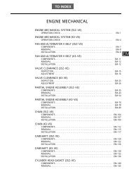
<strong>ENGINE</strong><br />
<strong>ENGINE</strong> <strong>CONTROL</strong><br />
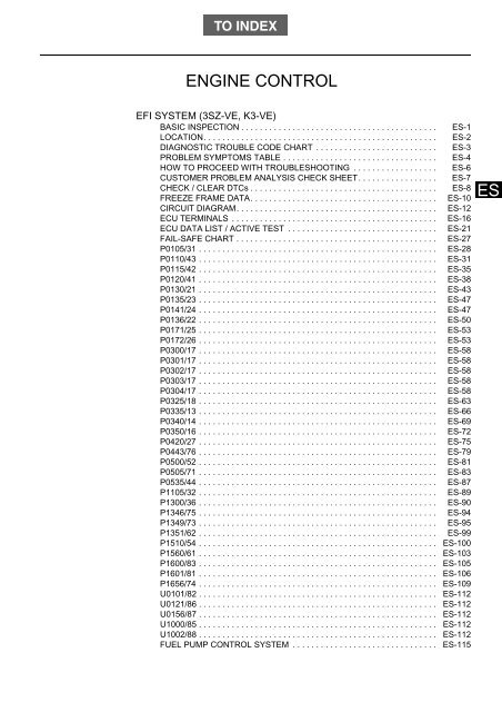
EFI SYSTEM (3SZ-VE, K3-VE)<br />
BASIC INSPECTION . . . . . . . . . . . . . . . . . . . . . . . . . . . . . . . . . . . . . . . . . . <strong>ES</strong>-1<br />
LOCATION. . . . . . . . . . . . . . . . . . . . . . . . . . . . . . . . . . . . . . . . . . . . . . . . . . <strong>ES</strong>-2<br />
DIAGNOSTIC TROUBLE CODE CHART . . . . . . . . . . . . . . . . . . . . . . . . . . <strong>ES</strong>-3<br />
PROBLEM SYMPTOMS TABLE . . . . . . . . . . . . . . . . . . . . . . . . . . . . . . . . . <strong>ES</strong>-4<br />
HOW TO PROCEED WITH TROUBL<strong>ES</strong>HOOTING . . . . . . . . . . . . . . . . . . <strong>ES</strong>-6<br />
CUSTOMER PROBLEM ANALYSIS CHECK SHEET. . . . . . . . . . . . . . . . . <strong>ES</strong>-7<br />
CHECK / CLEAR DTCs . . . . . . . . . . . . . . . . . . . . . . . . . . . . . . . . . . . . . . . . <strong>ES</strong>-8<br />
FREEZE FRAME DATA. . . . . . . . . . . . . . . . . . . . . . . . . . . . . . . . . . . . . . . . <strong>ES</strong>-10<br />
CIRCUIT DIAGRAM. . . . . . . . . . . . . . . . . . . . . . . . . . . . . . . . . . . . . . . . . . . <strong>ES</strong>-12<br />
ECU TERMINALS . . . . . . . . . . . . . . . . . . . . . . . . . . . . . . . . . . . . . . . . . . . . <strong>ES</strong>-16<br />
ECU DATA LIST / ACTIVE T<strong>ES</strong>T . . . . . . . . . . . . . . . . . . . . . . . . . . . . . . . . <strong>ES</strong>-21<br />
FAIL-SAFE CHART . . . . . . . . . . . . . . . . . . . . . . . . . . . . . . . . . . . . . . . . . . . <strong>ES</strong>-27<br />
P0105/31 . . . . . . . . . . . . . . . . . . . . . . . . . . . . . . . . . . . . . . . . . . . . . . . . . . . <strong>ES</strong>-28<br />
P0110/43 . . . . . . . . . . . . . . . . . . . . . . . . . . . . . . . . . . . . . . . . . . . . . . . . . . . <strong>ES</strong>-31<br />
P0115/42 . . . . . . . . . . . . . . . . . . . . . . . . . . . . . . . . . . . . . . . . . . . . . . . . . . . <strong>ES</strong>-35<br />
P0120/41 . . . . . . . . . . . . . . . . . . . . . . . . . . . . . . . . . . . . . . . . . . . . . . . . . . . <strong>ES</strong>-38<br />
P0130/21 . . . . . . . . . . . . . . . . . . . . . . . . . . . . . . . . . . . . . . . . . . . . . . . . . . . <strong>ES</strong>-43<br />
P0135/23 . . . . . . . . . . . . . . . . . . . . . . . . . . . . . . . . . . . . . . . . . . . . . . . . . . . <strong>ES</strong>-47<br />
P0141/24 . . . . . . . . . . . . . . . . . . . . . . . . . . . . . . . . . . . . . . . . . . . . . . . . . . . <strong>ES</strong>-47<br />
P0136/22 . . . . . . . . . . . . . . . . . . . . . . . . . . . . . . . . . . . . . . . . . . . . . . . . . . . <strong>ES</strong>-50<br />
P0171/25 . . . . . . . . . . . . . . . . . . . . . . . . . . . . . . . . . . . . . . . . . . . . . . . . . . . <strong>ES</strong>-53<br />
P0172/26 . . . . . . . . . . . . . . . . . . . . . . . . . . . . . . . . . . . . . . . . . . . . . . . . . . . <strong>ES</strong>-53<br />
P0300/17 . . . . . . . . . . . . . . . . . . . . . . . . . . . . . . . . . . . . . . . . . . . . . . . . . . . <strong>ES</strong>-58<br />
P0301/17 . . . . . . . . . . . . . . . . . . . . . . . . . . . . . . . . . . . . . . . . . . . . . . . . . . . <strong>ES</strong>-58<br />
P0302/17 . . . . . . . . . . . . . . . . . . . . . . . . . . . . . . . . . . . . . . . . . . . . . . . . . . . <strong>ES</strong>-58<br />
P0303/17 . . . . . . . . . . . . . . . . . . . . . . . . . . . . . . . . . . . . . . . . . . . . . . . . . . . <strong>ES</strong>-58<br />
P0304/17 . . . . . . . . . . . . . . . . . . . . . . . . . . . . . . . . . . . . . . . . . . . . . . . . . . . <strong>ES</strong>-58<br />
P0325/18 . . . . . . . . . . . . . . . . . . . . . . . . . . . . . . . . . . . . . . . . . . . . . . . . . . . <strong>ES</strong>-63<br />
P0335/13 . . . . . . . . . . . . . . . . . . . . . . . . . . . . . . . . . . . . . . . . . . . . . . . . . . . <strong>ES</strong>-66<br />
P0340/14 . . . . . . . . . . . . . . . . . . . . . . . . . . . . . . . . . . . . . . . . . . . . . . . . . . . <strong>ES</strong>-69<br />
P0350/16 . . . . . . . . . . . . . . . . . . . . . . . . . . . . . . . . . . . . . . . . . . . . . . . . . . . <strong>ES</strong>-72<br />
P0420/27 . . . . . . . . . . . . . . . . . . . . . . . . . . . . . . . . . . . . . . . . . . . . . . . . . . . <strong>ES</strong>-75<br />
P0443/76 . . . . . . . . . . . . . . . . . . . . . . . . . . . . . . . . . . . . . . . . . . . . . . . . . . . <strong>ES</strong>-79<br />
P0500/52 . . . . . . . . . . . . . . . . . . . . . . . . . . . . . . . . . . . . . . . . . . . . . . . . . . . <strong>ES</strong>-81<br />
P0505/71 . . . . . . . . . . . . . . . . . . . . . . . . . . . . . . . . . . . . . . . . . . . . . . . . . . . <strong>ES</strong>-83<br />
P0535/44 . . . . . . . . . . . . . . . . . . . . . . . . . . . . . . . . . . . . . . . . . . . . . . . . . . . <strong>ES</strong>-87<br />
P1105/32 . . . . . . . . . . . . . . . . . . . . . . . . . . . . . . . . . . . . . . . . . . . . . . . . . . . <strong>ES</strong>-89<br />
P1300/36 . . . . . . . . . . . . . . . . . . . . . . . . . . . . . . . . . . . . . . . . . . . . . . . . . . . <strong>ES</strong>-90<br />
P1346/75 . . . . . . . . . . . . . . . . . . . . . . . . . . . . . . . . . . . . . . . . . . . . . . . . . . . <strong>ES</strong>-94<br />
P1349/73 . . . . . . . . . . . . . . . . . . . . . . . . . . . . . . . . . . . . . . . . . . . . . . . . . . . <strong>ES</strong>-95<br />
P1351/62 . . . . . . . . . . . . . . . . . . . . . . . . . . . . . . . . . . . . . . . . . . . . . . . . . . . <strong>ES</strong>-99<br />
P1510/54 . . . . . . . . . . . . . . . . . . . . . . . . . . . . . . . . . . . . . . . . . . . . . . . . . . . <strong>ES</strong>-100<br />
P1560/61 . . . . . . . . . . . . . . . . . . . . . . . . . . . . . . . . . . . . . . . . . . . . . . . . . . . <strong>ES</strong>-103<br />
P1600/83 . . . . . . . . . . . . . . . . . . . . . . . . . . . . . . . . . . . . . . . . . . . . . . . . . . . <strong>ES</strong>-105<br />
P1601/81 . . . . . . . . . . . . . . . . . . . . . . . . . . . . . . . . . . . . . . . . . . . . . . . . . . . <strong>ES</strong>-106<br />
P1656/74 . . . . . . . . . . . . . . . . . . . . . . . . . . . . . . . . . . . . . . . . . . . . . . . . . . . <strong>ES</strong>-109<br />
U0101/82 . . . . . . . . . . . . . . . . . . . . . . . . . . . . . . . . . . . . . . . . . . . . . . . . . . . <strong>ES</strong>-112<br />
U0121/86 . . . . . . . . . . . . . . . . . . . . . . . . . . . . . . . . . . . . . . . . . . . . . . . . . . . <strong>ES</strong>-112<br />
U0156/87 . . . . . . . . . . . . . . . . . . . . . . . . . . . . . . . . . . . . . . . . . . . . . . . . . . . <strong>ES</strong>-112<br />
U1000/85 . . . . . . . . . . . . . . . . . . . . . . . . . . . . . . . . . . . . . . . . . . . . . . . . . . . <strong>ES</strong>-112<br />
U1002/88 . . . . . . . . . . . . . . . . . . . . . . . . . . . . . . . . . . . . . . . . . . . . . . . . . . . <strong>ES</strong>-112<br />
FUEL PUMP <strong>CONTROL</strong> SYSTEM . . . . . . . . . . . . . . . . . . . . . . . . . . . . . . . <strong>ES</strong>-115<br />
<strong>ES</strong>
<strong>ES</strong><br />
ECU POWER SOURCE SYSTEM. . . . . . . . . . . . . . . . . . . . . . . . . . . . . . . .<br />
THROTTLE BODY ASSEMBLY (3SZ-VE)<br />
COMPONENTS . . . . . . . . . . . . . . . . . . . . . . . . . . . . . . . . . . . . . . . . . . . . . .<br />
REMOVAL . . . . . . . . . . . . . . . . . . . . . . . . . . . . . . . . . . . . . . . . . . . . . . . . . .<br />
INSTALLATION . . . . . . . . . . . . . . . . . . . . . . . . . . . . . . . . . . . . . . . . . . . . . .<br />
INSPECTION . . . . . . . . . . . . . . . . . . . . . . . . . . . . . . . . . . . . . . . . . . . . . . . .<br />
KNOCK <strong>CONTROL</strong> SENSOR (3SZ-VE)<br />
COMPONENTS . . . . . . . . . . . . . . . . . . . . . . . . . . . . . . . . . . . . . . . . . . . . . .<br />
REMOVAL . . . . . . . . . . . . . . . . . . . . . . . . . . . . . . . . . . . . . . . . . . . . . . . . . .<br />
INSTALLATION . . . . . . . . . . . . . . . . . . . . . . . . . . . . . . . . . . . . . . . . . . . . . .<br />
INSPECTION . . . . . . . . . . . . . . . . . . . . . . . . . . . . . . . . . . . . . . . . . . . . . . . .<br />
CAMSHAFT TIMING OIL <strong>CONTROL</strong> VALVE ASSEMBLY (3SZ-VE)<br />
COMPONENTS . . . . . . . . . . . . . . . . . . . . . . . . . . . . . . . . . . . . . . . . . . . . . .<br />
REMOVAL . . . . . . . . . . . . . . . . . . . . . . . . . . . . . . . . . . . . . . . . . . . . . . . . . .<br />
INSTALLATION . . . . . . . . . . . . . . . . . . . . . . . . . . . . . . . . . . . . . . . . . . . . . .<br />
ON-VEHICLE INSPECTION . . . . . . . . . . . . . . . . . . . . . . . . . . . . . . . . . . . .<br />
INSPECTION . . . . . . . . . . . . . . . . . . . . . . . . . . . . . . . . . . . . . . . . . . . . . . . .<br />
<strong>ENGINE</strong> <strong>CONTROL</strong> COMPUTER (3SZ-VEÅj<br />
COMPONENTS . . . . . . . . . . . . . . . . . . . . . . . . . . . . . . . . . . . . . . . . . . . . . .<br />
REMOVAL . . . . . . . . . . . . . . . . . . . . . . . . . . . . . . . . . . . . . . . . . . . . . . . . . .<br />
INSTALLATION . . . . . . . . . . . . . . . . . . . . . . . . . . . . . . . . . . . . . . . . . . . . . .<br />
E.F.I. WATER TEMPERATURE (3SZ-VE)<br />
INSPECTION . . . . . . . . . . . . . . . . . . . . . . . . . . . . . . . . . . . . . . . . . . . . . . . .<br />
E.F.I. COMPUTER RELAY (3SZ-VE)<br />
INSPECTION . . . . . . . . . . . . . . . . . . . . . . . . . . . . . . . . . . . . . . . . . . . . . . . .<br />
THROTTLE POSITION SENSOR (3SZ-VE)<br />
INSPECTION . . . . . . . . . . . . . . . . . . . . . . . . . . . . . . . . . . . . . . . . . . . . . . . .<br />
<strong>ES</strong>-120<br />
<strong>ES</strong>-125<br />
<strong>ES</strong>-127<br />
<strong>ES</strong>-128<br />
<strong>ES</strong>-129<br />
<strong>ES</strong>-130<br />
<strong>ES</strong>-133<br />
<strong>ES</strong>-134<br />
<strong>ES</strong>-134<br />
<strong>ES</strong>-135<br />
<strong>ES</strong>-136<br />
<strong>ES</strong>-136<br />
<strong>ES</strong>-136<br />
<strong>ES</strong>-137<br />
<strong>ES</strong>-138<br />
<strong>ES</strong>-139<br />
<strong>ES</strong>-139<br />
<strong>ES</strong>-140<br />
<strong>ES</strong>-141<br />
<strong>ES</strong>-142
EFI SYSTEM (3SZ-VE, K3-VE)<br />
<strong>ENGINE</strong> <strong>CONTROL</strong><br />
<strong>ENGINE</strong> <strong>CONTROL</strong> - EFI SYSTEM (3SZ-VE, K3-VE)<br />
BASIC INSPECTION<br />
<strong>ES</strong>–1<br />
HINT:<br />
If the malfunction cannot be determined by troubleshooting, the problem<br />
area can be narrowed down by performing the following basic inspection.<br />
1. CHECK BATTERY VOLTAGE<br />
(a) Check the condition of the battery.(See page CH - 3.)<br />
2. CHECK WHETHER <strong>ENGINE</strong> CRANKS<br />
(a) Make sure that the engine cranks.<br />
HINT:<br />
If the engine does not crank, check the starting systems.<br />
<strong>ES</strong><br />
3. CHECK WHETHER <strong>ENGINE</strong> STARTS<br />
(a) Make sure that the engine starts.<br />
HINT:<br />
If the engine does not start, check fuel pressure and spark.<br />
4. CHECK AIR FILTER<br />
(a) Check the air filter.<br />
HINT:<br />
If the air filter is dirty, clean or replace it.<br />
5. CHECK <strong>ENGINE</strong> IDLE SPEED (See page EM - 2)<br />
6. CHECK IGNITION TIMING (See page EM - 1)<br />
7. CHECK FUEL PR<strong>ES</strong>SURE (See page FU - 3)<br />
8. CHECK FOR SPARK (See page IG - 1)<br />
9. CHECK COMPR<strong>ES</strong>SION (See page EM - 2)
<strong>ES</strong>–2<br />
<strong>ENGINE</strong> <strong>CONTROL</strong> - EFI SYSTEM (3SZ-VE, K3-VE)<br />
LOCATION<br />
<strong>ENGINE</strong> ROOM R/B<br />
EFI FUSE<br />
FAN RELAY<br />
INSTRUMENT PANEL J/B<br />
ST RELAY<br />
E/G FUSE<br />
<strong>ES</strong><br />
EFI RELAY<br />
F/P RELAY<br />
AM2 FUSE<br />
THROTTLE BODY ASSEMBLY<br />
THROTTLE POSITION SENSOR<br />
ISCV<br />
EVAP PURGE VSV<br />
DLC<br />
COMBINATION METER<br />
VACUUM SENSOR<br />
CAMSHAFT POSITION SENSOR<br />
INLET AIR TEMPERATURE<br />
SENSOR<br />
FUEL INJECTOR ASSEMBLY<br />
FUEL PUMP<br />
AUTOMATIC <strong>CONTROL</strong><br />
COMPUTER<br />
<strong>ENGINE</strong> <strong>CONTROL</strong> COMPUTER<br />
OXYGEN SENSOR NO. 2<br />
KNOCK <strong>CONTROL</strong> SENSOR<br />
IGNITION COIL ASSEMBLY<br />
CRANKSHAFT POSITION SENSOR<br />
COOLANT TEMPERATURE<br />
OXYGEN SENSOR<br />
CAMSHAFT TIMING OIL <strong>CONTROL</strong> VALVE ASSEMBLY<br />
A135187J02
<strong>ENGINE</strong> <strong>CONTROL</strong> - EFI SYSTEM (3SZ-VE, K3-VE)<br />
<strong>ES</strong>–3<br />
DIAGNOSTIC TROUBLE CODE CHART<br />
DTC No. Diagnostic Item Lamp Code Memory See Page<br />
P0105/31<br />
P0110/43<br />
P0115/42<br />
P0120/41<br />
P0130/21<br />
P0135/23<br />
Air intake pressure sensor<br />
signal system<br />
Intake air temperature<br />
sensor signal system<br />
Coolant temperature<br />
sensor signal system<br />
Throttle sensor signal<br />
system<br />
Front O2 sensor signal<br />
system<br />
Front O2 sensor heater<br />
signal system<br />
◦ ◦ <strong>ES</strong> - 28<br />
◦ ◦ <strong>ES</strong> - 31<br />
◦ ◦ <strong>ES</strong> - 35<br />
◦ ◦ <strong>ES</strong> - 38<br />
◦ ◦ <strong>ES</strong> - 43<br />
◦ ◦ <strong>ES</strong> - 47<br />
P0136/22<br />
Rear O2 sensor signal<br />
system<br />
◦ ◦ <strong>ES</strong> - 50<br />
P0141/24 Rear O2 sensor heater ◦ ◦ <strong>ES</strong> - 47<br />
P0171/25<br />
Fuel system (lean<br />
malfunction)<br />
◦ ◦ <strong>ES</strong> - 53<br />
P0172/26<br />
Fuel system (rich<br />
malfunction)<br />
◦ ◦ <strong>ES</strong> - 53<br />
P0300/17 Misfire ◦ ◦ <strong>ES</strong> - 58<br />
P0301/17 Misfire (#1 cylinder) ◦ ◦ <strong>ES</strong> - 58<br />
P0302/17 Misfire (#2 cylinder) ◦ ◦ <strong>ES</strong> - 58<br />
P0303/17 Misfire (#3 cylinder) ◦ ◦ <strong>ES</strong> - 58<br />
P0304/17 Misfire (#4 cylinder) ◦ ◦ <strong>ES</strong> - 58<br />
P0325/18<br />
P0335/13<br />
Knock sensor signal<br />
system<br />
Engine revolution sensor<br />
signal system<br />
× ◦ <strong>ES</strong> - 63<br />
◦ ◦ <strong>ES</strong> - 66<br />
P0340/14<br />
Cam angle sensor signal<br />
system<br />
◦ ◦ <strong>ES</strong> - 69<br />
P0350/16 Ignition primary system ◦ ◦ <strong>ES</strong> - 72<br />
P0443/76 EVAP purge VSV ◦ ◦ <strong>ES</strong> - 79<br />
P0420/27 Catalyst deterioration ◦ ◦ <strong>ES</strong> - 75<br />
P0500/52<br />
Vehicle speed signal<br />
system<br />
◦ ◦ <strong>ES</strong> - 81<br />
P0505/71 ISC valve system ◦ ◦ <strong>ES</strong> - 83<br />
P0535/44<br />
A/C evaporator<br />
temperature sensor signal<br />
system<br />
× ◦ <strong>ES</strong> - 87<br />
P1105/32<br />
Atmospheric pressure<br />
sensor signal system<br />
◦ ◦ <strong>ES</strong> - 89<br />
P1300/36 Ionic current system ◦ ◦ <strong>ES</strong> - 90<br />
P1346/75<br />
P1349/73<br />
VVT control system (valve<br />
timing fail)<br />
VVT control (advance<br />
angle and retard angle fail)<br />
◦ ◦ <strong>ES</strong> - 94<br />
◦ ◦ <strong>ES</strong> - 95<br />
P1351/62<br />
Timing chain control<br />
system<br />
× ◦ <strong>ES</strong> - 99<br />
P1510/54 Starter signal system ◦ ◦ <strong>ES</strong> - 100<br />
P1560/61<br />
Short to back up power<br />
source<br />
◦ ◦ <strong>ES</strong> - 103<br />
<strong>ES</strong>
<strong>ES</strong>–4<br />
<strong>ENGINE</strong> <strong>CONTROL</strong> - EFI SYSTEM (3SZ-VE, K3-VE)<br />
<strong>ES</strong><br />
DTC No. Diagnostic Item Lamp Code Memory See Page<br />
P1600/83<br />
P1601/81<br />
Keyless system/<br />
immobiliser system<br />
communication system<br />
(malfunction in ECU)<br />
Keyless / immobiliser<br />
system communication<br />
system (code does not<br />
match, communication<br />
error)<br />
× ◦ <strong>ES</strong> - 105<br />
× ◦ <strong>ES</strong> - 106<br />
P1656/74 OCV control system ◦ ◦ <strong>ES</strong> - 109<br />
U0101/82<br />
U0121/86<br />
U0156/87<br />
EAT/ CVT communication<br />
(reception)<br />
ABS communication<br />
(reception)<br />
Meter communication<br />
(receiving)<br />
◦ ◦ <strong>ES</strong> - 112<br />
◦ ◦ <strong>ES</strong> - 112<br />
◦ ◦ <strong>ES</strong> - 112<br />
U1000/85<br />
EAT communication<br />
(transmission)<br />
◦ ◦ <strong>ES</strong> - 112<br />
U1002/88 CAN communication ◦ ◦ <strong>ES</strong> - 112<br />
PROBLEM SYMPTOMS TABLE<br />
Symptom Suspected Area See Page<br />
1. Starter assembly ST - 10<br />
Engine does not crank<br />
2. Starter relay ST - 21<br />
3. Neutral start switch system AT - 57<br />
1. See flowchart (ECU power source) <strong>ES</strong> - 120<br />
2. Igniter system IG - 1<br />
No initial combustion (engine does not start)<br />
3. See flowchart (fuel pump control system) <strong>ES</strong> - 115<br />
4. Injector FU - 12<br />
5. Crank position sensor system IG - 14<br />
1. See flowchart (fuel pump control system) <strong>ES</strong> - 115<br />
Incomplete combustion (engine does not start)<br />
2. Igniter system IG - 1<br />
3. Injector FU - 12<br />
4. Crank position sensor system IG - 14<br />
1. Throttle body system <strong>ES</strong> - 129<br />
2. See flowchart (fuel pump control system) <strong>ES</strong> - 115<br />
3. Igniter system IG - 1<br />
Engine does not start but cranks normally)<br />
4. Spark plug IG - 18<br />
5. Compression EM - 2<br />
6. Injector FU - 12<br />
7. Crank position sensor system IG - 14<br />
1. Throttle body system <strong>ES</strong> - 129<br />
2. See flowchart (fuel pump control system) <strong>ES</strong> - 115<br />
Engine does not start (when cold)<br />
3. Injector FU - 12<br />
4. Igniter system IG - 1<br />
5. Spark plug IG - 18<br />
6. Crank position sensor system IG - 14
<strong>ENGINE</strong> <strong>CONTROL</strong> - EFI SYSTEM (3SZ-VE, K3-VE)<br />
<strong>ES</strong>–5<br />
Symptom Suspected Area See Page<br />
1. Throttle body system <strong>ES</strong> - 129<br />
2. See flowchart (fuel pump control system) <strong>ES</strong> - 115<br />
Engine does not start (when warm)<br />
3. Injector FU - 12<br />
4. Igniter system IG - 1<br />
5. Spark plug IG - 18<br />
6. Crank position sensor system IG - 14<br />
Fast idle problem<br />
1. Throttle body system <strong>ES</strong> - 129<br />
2. Spark plug IG - 18<br />
1. Throttle body system <strong>ES</strong> - 129<br />
Idle speed is too high<br />
2. See flowchart (ECU power source) <strong>ES</strong> - 120<br />
3. Neutral start switch system AT - 57<br />
1. Throttle body system <strong>ES</strong> - 129<br />
Idle speed is too low<br />
2. Neutral start switch system AT - 57<br />
3. See flowchart (fuel pump control system) <strong>ES</strong> - 115<br />
4. Injector FU - 12<br />
1. Throttle body system <strong>ES</strong> - 129<br />
2. Injector FU - 12<br />
Idle is unstable<br />
3. Igniter system IG - 1<br />
4. Compression EM - 2<br />
5. See flowchart (fuel pump control system) <strong>ES</strong> - 115<br />
6. Spark plug IG - 18<br />
1. Throttle body system <strong>ES</strong> - 129<br />
Hunting<br />
2. See flowchart (ECU power source) <strong>ES</strong> - 120<br />
3. See flowchart (fuel pump control system) <strong>ES</strong> - 115<br />
4. Spark plug IG - 17<br />
1. See flowchart (fuel pump control system) <strong>ES</strong> - 115<br />
Stumbling, poor acceleration<br />
2. Injector FU - 12<br />
3. Igniter system IG - 1<br />
4. Spark plug IG - 17<br />
After fire<br />
1. Igniter system IG - 1<br />
2. Injector FU - 12<br />
1. See flowchart (fuel pump control system) <strong>ES</strong> - 115<br />
Surging<br />
2. Spark plug IG - 17<br />
3. Injector FU - 12<br />
1. See flowchart (fuel pump control system) <strong>ES</strong> - 115<br />
Engine stall (right after starting engine)<br />
2. Throttle body system <strong>ES</strong> - 129<br />
3. Crank position sensor system IG - 14<br />
4. Igniter system IG - 1<br />
1. Injector FU - 12<br />
2. Throttle body system <strong>ES</strong> - 129<br />
Engine stall (right after slowing down)<br />
3. Engine control computer <strong>ES</strong> - 16<br />
4. Crank position sensor system IG - 14<br />
5. Igniter system IG - 1<br />
1. Neutral start switch system AT - 57<br />
Engine stall (when the shift lever is in the D position)<br />
2. Throttle body system <strong>ES</strong> - 129<br />
3. Crank position sensor system IG - 14<br />
4. Igniter system IG - 1<br />
<strong>ES</strong>
<strong>ES</strong>–6<br />
<strong>ENGINE</strong> <strong>CONTROL</strong> - EFI SYSTEM (3SZ-VE, K3-VE)<br />
HOW TO PROCEED WITH<br />
TROUBL<strong>ES</strong>HOOTING<br />
1 VEHICLE BROUGHT TO WORKSHOP<br />
<strong>ES</strong><br />
2 CONDUCT CUSTOMER PROBLEM ANALYSIS AND CHECK SYMPTOMS (See page <strong>ES</strong> - 7.)<br />
3 CHECK CAN COMMUNICATION SYSTEM (See page CA - 4.)<br />
(a)<br />
Using the DS-II, select CAN BUS DIAGNOSIS / CHECK ECU<br />
CONNECTED TO CAN BUS LINE screen (see CA - 8), and make<br />
sure all ECU and sensors that are connected to the CAN<br />
communication are displayed on the screen.<br />
NG<br />
GO TO CAN COMMUNICATION SECTION<br />
OK<br />
4 CHECK FOR DIAGNOSTIC TROUBLE COD<strong>ES</strong> (See page <strong>ES</strong> - 8.)<br />
(a)<br />
(b)<br />
(c)<br />
B<br />
Check for DTCs and freeze frame data.<br />
Delete DTCs and freeze frame data.<br />
Recheck for DTCs.<br />
(1) If DTCs are present, go to A.<br />
(2) If DTCs are not present, go to B.<br />
GO TO STEP 7<br />
A<br />
5 TROUBL<strong>ES</strong>HOOT USING DTCS OR DIAGNOSTIC TROUBLE CODE CHART (MAIN SUSPECTED<br />
AREAS)<br />
(a) If the location of the problem is determined, go to A.<br />
(b) If the location of the problem is not determined, go to B.<br />
A<br />
B<br />
GO TO STEP 12<br />
GO TO STEP 9<br />
6 PROBLEM SYMPTOMS TABLE (See page <strong>ES</strong> - 4.)<br />
(a) If the location of the problem is determined, go to A.<br />
(b) If the location of the problem is not determined, go to B.
<strong>ENGINE</strong> <strong>CONTROL</strong> - EFI SYSTEM (3SZ-VE, K3-VE)<br />
<strong>ES</strong>–7<br />
A<br />
GO TO STEP 12<br />
B<br />
7 BASIC INSPECTION (See page <strong>ES</strong> - 1.)<br />
(a) If the location of the problem is determined, go to A.<br />
(b) If the location of the problem is not determined, go to B.<br />
B<br />
A<br />
GO TO STEP 12<br />
<strong>ES</strong><br />
8 CHECK USING DS-II (See page <strong>ES</strong> - 21.)<br />
(a) Select ECU data list or active test.<br />
(b) If the location of the problem is determined, go to A.<br />
(c) If the location of the problem is not determined, go to B.<br />
A<br />
GO TO STEP 12<br />
B<br />
9 CHECK VOLTAGE OF ECU VOLTAGE AND CIRCUIT (See page <strong>ES</strong> - 16.)<br />
10 REPAIR PROBLEM AREAS<br />
11 CHECK FOR DIAGNOSTIC TROUBLE COD<strong>ES</strong> (See page <strong>ES</strong> - 8.)<br />
END<br />
CUSTOMER PROBLEM ANALYSIS<br />
CHECK SHEET<br />
1. Ask the customer about problems and concerns.<br />
(a) Follow the previous troubleshooting procedure, and use the<br />
customer problem analysis check sheet to make sure that the<br />
proper questions are asked when interviewing the customer<br />
about problems.
<strong>ES</strong>–8<br />
<strong>ENGINE</strong> <strong>CONTROL</strong> - EFI SYSTEM (3SZ-VE, K3-VE)<br />
Engine Problem Diagnosis Check Sheet<br />
Model<br />
VIN<br />
Accessories<br />
Date vehicle brought in<br />
Date registered<br />
Date problem first occurred<br />
Service history<br />
Registration No.<br />
Odometer reading<br />
No/Yes (__times)<br />
km<br />
<strong>ES</strong><br />
Previous vehicle<br />
Customer profile/characteristics<br />
Description of symptoms<br />
Main region/purpose of travel<br />
Warning light illumination Off/On ( )<br />
Check<br />
Results<br />
System Conditions<br />
Speed problem first<br />
occurred( )km/h<br />
Shift position ( ) range<br />
Starting off<br />
Immediately after<br />
start off<br />
( ) min after start<br />
After ( )min driving<br />
Cold<br />
Warm<br />
Idling<br />
Others ( )<br />
Additional Items<br />
Driving<br />
Conditions<br />
Starting off<br />
Cruising<br />
Increasing<br />
speed<br />
Decreasing<br />
speed<br />
Braking<br />
Turning<br />
Stopped<br />
Not related<br />
Others<br />
( )<br />
Road Conditions<br />
Level<br />
Uphill<br />
Downhill<br />
Dry paved road<br />
Wet paved road<br />
Unpaved/rough<br />
road<br />
Snowy/icy road<br />
Uneven,<br />
manholes etc.<br />
Others ( )<br />
Others<br />
Accelerator<br />
opening<br />
( )%<br />
Ambient air<br />
temperature<br />
( )<br />
Weather<br />
( )<br />
Problem<br />
Frequency<br />
Always<br />
One time only<br />
Sometimes<br />
(_)times a day<br />
(_)times a week<br />
(_)times a month<br />
DTC Inspection<br />
Malfunction Indicator<br />
Lamp (MIL) Off/On<br />
Normal Code(s)<br />
Malfunction code(s)(all noted)<br />
Fuel pressure when<br />
engine stopped<br />
Fuel pressure 1 min.<br />
after engine stopped<br />
Problem details<br />
Inspection Driving conditions and location when problem first<br />
Results occurred and reoccurred<br />
Reoccurrence conditions<br />
Always Occasional Once problem occurs, it continues Does not reoccur<br />
Dealer Name Office Person in charge Technician<br />
A066666<br />
CHECK / CLEAR DTCs<br />
1. PREPARE FOR INSPECTION<br />
(a) Make sure that the throttle valve is fully closed.
<strong>ENGINE</strong> <strong>CONTROL</strong> - EFI SYSTEM (3SZ-VE, K3-VE)<br />
<strong>ES</strong>–9<br />
(b)<br />
(c)<br />
Move the shift lever to the N or P position.<br />
Turn off the air conditioner.<br />
DS<br />
DLC<br />
A136722J02<br />
2. CHECK DTCs (using DS-II)<br />
(a) Connect the DS-II to the DLC.<br />
(b) Turn the ignition switch to the ON position.<br />
(c) Turn the DS-II power ON.<br />
(d) Following the prompts on the screen, select CHECK DTCs/<br />
FREEZE FRAME DATA on the DIAGNOSIS - EFI scree, and<br />
check for DTCs.<br />
HINT:<br />
If a DTC is displayed on the DS-II, see IN - 30.<br />
<strong>ES</strong><br />
EFIT<br />
E<br />
G100942<br />
3. CHECK DTCs (using the check engine warning light)<br />
NOTICE:<br />
• Turn the ignition switch to the ON position before reading the<br />
DTCs, and check that the check engine warning light is<br />
flashing.<br />
• The CHECK MODE cannot be used.<br />
(a) Turn the ignition switch off.<br />
(b) Using the diagnosis check wire, short terminals 12 (EFIT) and 4<br />
(E) of the DLC.<br />
SST 09843-18020-000<br />
NOTICE:<br />
• Do not connect the diagnosis check wire to the wrong<br />
terminals. Doing so may cause malfunctions.<br />
• Use only the dedicated diagnosis check wire.<br />
Normal Code<br />
0.25 Sec.<br />
0.25 Sec.<br />
2 Sec.<br />
Abnormal Code (Example [11] [23] )<br />
4 Sec. 1.5 Sec. 2.5 Sec.<br />
0.5 Sec. 0.5 Sec.<br />
Repeated<br />
C040092J07<br />
(c) Turn the ignition switch to the ON position, and count the<br />
number of flashes of the check engine warning light.<br />
HINT:<br />
• If the indicator light does not indicate a DTC (the light does<br />
not blink), there may be a malfunction in the TC terminal, VC<br />
terminal, or the computer.<br />
• If the check engine warning light remains on, the wire<br />
harness may have a short circuit (due to being pinched or<br />
for other reasons) or the computer may be malfunctioning.<br />
• If an irrelevant DTC is detected, the computer may be<br />
malfunctioning.<br />
• If the check engine warning light comes on at engine speed<br />
of approximately1000 r/min or more and no DTC is output,<br />
turn the ignition switch to the OFF position and recheck.<br />
(d) Disconnect diagnosis check wire No.2.<br />
4. CHECK FREEZE DATA (using DS-II)<br />
(a) Using the DS-II, follow the prompts on the screen, and select<br />
the DTC that records the freeze data (marked !) from the DTC /<br />
FREEZE DATA screen.<br />
HINT:<br />
• The engine condition (ECU data) before and after DTCs are<br />
detected can be checked using the time series freeze frame<br />
data. (See page <strong>ES</strong> - 10.)<br />
• The time series freeze frame data is helpful in<br />
troubleshooting when the symptom cannot be reproduced.
<strong>ES</strong>–10<br />
<strong>ENGINE</strong> <strong>CONTROL</strong> - EFI SYSTEM (3SZ-VE, K3-VE)<br />
5. DELETE RECORDED DTCs (using DS-II)<br />
(a) Following the prompts on the screen, select the DTC / FREEZE<br />
DATA screen and delete the DTCs.<br />
NOTICE:<br />
• If the DTCs cannot be deleted, turn the ignition switch<br />
off, then perform the procedure again.<br />
• Until the cause of problems are clarified, do not delete<br />
the DTCs using the DS-II.<br />
• Write the DTCs down before deleting them.<br />
<strong>ES</strong><br />
Engine Room R/B<br />
EFI Fuse<br />
A133909J01<br />
6. DELETE DTCs (by removing a fuse)<br />
(a) The recorded codes can be deleted by removing the EFI fuse<br />
(15A) for more than 60 seconds after turning the ignition switch<br />
to the OFF position.<br />
NOTICE:<br />
• Be sure to clear the DTCs and check that a normal code<br />
is output after the EFI system inspection is finished.<br />
• Do not delete the DTCs by clearing the battery<br />
(removing a fuse) until the cause of the problems is<br />
clarified.<br />
• Write the DTCs down before deleting them.<br />
Freeze Frame Data<br />
1. CHECK FREEZE FRAME DATA<br />
(a) If the symptom can not be reproduced even though a DTC is<br />
detected, check the freeze frame data.<br />
(1) Connect the DS-II to the DLC.<br />
(2) Turn the ignition switch to the ON position.<br />
(3) Select DIAGNOSIS → EFI → DTC / FREEZE DATA.<br />
(4) Detected DTCs will be displayed on the DTC screen.<br />
(5) Select the DTCs to check the desired freeze data.<br />
HINT:<br />
The DTCs are marked with the character, !, and the<br />
highlighted codes contain freeze data.<br />
Time Sequence Of Data Recording Timing<br />
DTC Detection Point<br />
▼<br />
1 2 3<br />
:Time Sequence of Data Recording Point<br />
(Recorded At 0.5 Second Intervals)<br />
A138074J01<br />
2. CHECK TIME SERI<strong>ES</strong> FREEZE FRAME DATA<br />
(a) Select the item to check the desired time series freeze data on<br />
the freeze data screen.<br />
HINT:<br />
• The previous version of freeze data recorded ECU data only<br />
when DTCs occurred (when detected), but time series<br />
freeze frame data also records ECU data before and after<br />
DTCs are detected.<br />
• Time series freeze frame data can be checked when TIME<br />
SERI<strong>ES</strong> FREEZE DATA CAN BE CHECKED is displayed<br />
on the freeze data screen.<br />
• The time series freeze frame data can display up to 3 data<br />
points, including the DTC inspection point, 1 point for before<br />
inspection, and 1 point after inspection.<br />
3. FREEZE DATA CHART<br />
Item<br />
Coolant temperature<br />
Air intake pressure<br />
Engine speed<br />
Shorted Item<br />
ECT<br />
MAP<br />
r/min
<strong>ENGINE</strong> <strong>CONTROL</strong> - EFI SYSTEM (3SZ-VE, K3-VE)<br />
<strong>ES</strong>–11<br />
Item<br />
Vehicle speed<br />
Ignition timing advance angle<br />
Injection volume<br />
Injection timing<br />
Shorted Item<br />
VS<br />
ITA<br />
TAUX<br />
TAUZ<br />
<strong>ES</strong>
<strong>ES</strong>–12<br />
<strong>ENGINE</strong> <strong>CONTROL</strong> - EFI SYSTEM (3SZ-VE, K3-VE)<br />
CIRCUIT DIAGRAM<br />
General Export<br />
Starter<br />
AM2<br />
A/T ECU<br />
ST Relay<br />
<strong>ES</strong><br />
Battery<br />
Ignition Switch<br />
MAIN EFI 15A<br />
E/G 10A<br />
ST 7.5A<br />
120<br />
IGSW<br />
STSW<br />
107<br />
38<br />
BAT<br />
59<br />
39<br />
N1+<br />
MRO<br />
128<br />
N1-<br />
1<br />
2<br />
Crankshaft<br />
Position Sensor<br />
EFI Relay<br />
27<br />
+B<br />
N2+<br />
N2-<br />
58<br />
127<br />
1<br />
2<br />
Camshaft<br />
Position Sensor<br />
1<br />
F/P Relay<br />
35<br />
To Fuel Pump<br />
Injector No. 1<br />
2 24<br />
Injector No. 2<br />
FC1<br />
#10<br />
KNK<br />
OX1<br />
OXH1<br />
OX2<br />
121<br />
123<br />
15<br />
18<br />
2 Knock Control 1<br />
Sensor<br />
2<br />
1<br />
4<br />
Oxygen Sensor<br />
3<br />
To +B<br />
1 Oxygen Sensor 2<br />
NO. 2<br />
1<br />
1<br />
Injector No. 3<br />
2<br />
2<br />
23<br />
22<br />
#20<br />
#30<br />
VC<br />
VTH<br />
56<br />
53<br />
1 2<br />
Throttle Position<br />
3 Sensor<br />
1<br />
Injector No. 4<br />
2<br />
21<br />
#40<br />
THW<br />
54<br />
2 1<br />
Coolant Temperature<br />
2<br />
EVAP Purge VSV<br />
1<br />
16<br />
PRG<br />
THA<br />
E2<br />
55<br />
19<br />
1 Inlet Air Temperature 2<br />
Sensor<br />
Indicator E1<br />
2<br />
3<br />
ISCV<br />
1<br />
65<br />
ISC<br />
E01<br />
E1<br />
20<br />
125<br />
Engine Control Computer<br />
A135479J01
<strong>ENGINE</strong> <strong>CONTROL</strong> - EFI SYSTEM (3SZ-VE, K3-VE)<br />
<strong>ES</strong>–13<br />
General Export<br />
Stop Light Switch Assembly<br />
To IG2<br />
1<br />
4<br />
Ignition Coil Assembly<br />
(No. 1 Cylinder)<br />
3<br />
63<br />
IG1<br />
STP<br />
43<br />
Stop Light<br />
STP 10A<br />
To Battery<br />
1<br />
4<br />
1<br />
4<br />
Ignition Coil Assembly<br />
(No. 2 Cylinder)<br />
Ignition Coil Assembly<br />
(No. 3 Cylinder)<br />
3<br />
3<br />
62<br />
61<br />
IG2<br />
IG3<br />
DEF<br />
OCV+<br />
11<br />
26<br />
Defogger<br />
Defogger Switch<br />
1<br />
OCV<br />
2<br />
To DEF Fuse<br />
<strong>ES</strong><br />
1<br />
4<br />
Ignition Coil Assembly<br />
(No. 4 Cylinder)<br />
3<br />
60<br />
IG4<br />
OCV-<br />
VCPM<br />
PIM<br />
25<br />
57<br />
52<br />
3<br />
2<br />
Vacuum Sensor<br />
1<br />
To Ignition Plugs<br />
E2PM<br />
122<br />
ACEV<br />
45<br />
1<br />
A/C Evaporator<br />
Temperautre Sensor<br />
2<br />
Engine Check Light<br />
E21<br />
116<br />
13<br />
W<br />
EPS<br />
12<br />
P/S Oil Pressure Switch<br />
FAN Relay<br />
Fan Motor<br />
37<br />
FAN1<br />
SIO2<br />
117<br />
9<br />
Immobiliser ECU*<br />
FPOF<br />
44<br />
Airbag ECU<br />
Alternator<br />
135<br />
ALT<br />
BLW<br />
ACSW<br />
42<br />
45<br />
To A/C<br />
Meter ECU<br />
9<br />
8<br />
HCAN<br />
LCAN<br />
REV<br />
118<br />
Tachometer<br />
A/T ECU<br />
7<br />
6<br />
4<br />
CANH<br />
CANL<br />
ATNE<br />
EFIT<br />
113<br />
DLC<br />
Engine Control Computer<br />
: Immobiliser Equipped Vehicles<br />
A135480J01
<strong>ES</strong>–14<br />
<strong>ENGINE</strong> <strong>CONTROL</strong> - EFI SYSTEM (3SZ-VE, K3-VE)<br />
EU Specifications<br />
Starter<br />
AM2<br />
A/T ECU<br />
ST Relay<br />
Ignition Switch<br />
MAIN EFI15A E/G 10A<br />
ST 7.5A<br />
<strong>ES</strong><br />
Battery<br />
120<br />
38<br />
39<br />
IGSW 107<br />
STSW<br />
BAT<br />
59<br />
N1+<br />
MRO<br />
128<br />
N1-<br />
1<br />
2<br />
Crankshaft Position<br />
Sensor<br />
EFI Relay<br />
27<br />
+B<br />
N2+<br />
N2-<br />
58<br />
127<br />
1<br />
2<br />
Camshaft Position<br />
Sensor<br />
1<br />
1<br />
F/P Relay<br />
34<br />
To Fuel Pump<br />
Injector No. 1<br />
2 24<br />
Injector No. 2<br />
2 23<br />
FAN2<br />
#10<br />
#20<br />
KNK<br />
OX1<br />
OXH1<br />
OX2<br />
OXH2<br />
121<br />
123<br />
15<br />
2 Knock Control 1<br />
Sensor<br />
2<br />
1<br />
18<br />
2<br />
14 1<br />
Oxygen Sensor<br />
Oxygen Sensor<br />
NO. 2<br />
4<br />
3<br />
4<br />
3<br />
To B<br />
To B<br />
1<br />
Injector No. 3<br />
2<br />
22<br />
#30<br />
VC<br />
VTH<br />
56<br />
53<br />
1 2<br />
Throttle Position<br />
3<br />
Sensor<br />
1<br />
Injector No. 4<br />
2<br />
21<br />
#40<br />
THW<br />
54<br />
2 Coolant Temperature 1<br />
Sensor<br />
2<br />
EVAP Control VSV<br />
1<br />
16<br />
PRG<br />
THA<br />
E2<br />
55<br />
19<br />
1 Intake Air Temperature 2<br />
Sensor<br />
To E1<br />
2<br />
3<br />
ISCV<br />
1<br />
65<br />
ISC<br />
E01<br />
E1<br />
20<br />
125<br />
Engine Control Computer<br />
A138429J01
<strong>ENGINE</strong> <strong>CONTROL</strong> - EFI SYSTEM (3SZ-VE, K3-VE)<br />
<strong>ES</strong>–15<br />
EU Specifications<br />
Stop Light Switch Assembly<br />
To IG2<br />
1<br />
4<br />
Ignition Coil Assembly<br />
(No. 1 Cylinder)<br />
3<br />
2<br />
63<br />
51<br />
IG1<br />
ICMB1<br />
STP<br />
43<br />
STP 10A<br />
To Battery<br />
Stop Light<br />
1<br />
4<br />
1<br />
4<br />
Ignition Coil Assembly<br />
(No. 2 Cylinder)<br />
Ignition Coil Assembly<br />
(No. 3 Cylinder)<br />
3<br />
2<br />
3<br />
2<br />
62<br />
50<br />
61<br />
49<br />
IG2<br />
ICMB2<br />
IG3<br />
ICMB3<br />
DEF<br />
OCV+<br />
11<br />
26<br />
Defogger<br />
Defogger Switch<br />
1<br />
OCV<br />
2<br />
To DEF Fuse<br />
<strong>ES</strong><br />
1<br />
4<br />
Ignition Coil Assembly<br />
(No. 4 Cylinder)<br />
3<br />
2<br />
61<br />
48<br />
IG4<br />
ICMB4<br />
OCV-<br />
VCPM<br />
PIM<br />
25<br />
57<br />
52<br />
3<br />
2<br />
Intake Air<br />
Pressure Sensor<br />
1<br />
Condensor<br />
To Ignition Plugs<br />
E2PM<br />
122<br />
ACEV<br />
45<br />
1<br />
A/C Evaporator<br />
Temperature Sensor<br />
2<br />
Engine Check Light<br />
E21<br />
116<br />
13<br />
W<br />
PST<br />
12<br />
P/S Oil Pressure Switch<br />
Fan Relay<br />
Fan Motor<br />
37<br />
FAN1<br />
SIO2<br />
117<br />
9<br />
Immobiliser ECU<br />
FPOF<br />
44<br />
Airbag ECU<br />
Alternator<br />
135<br />
ALT<br />
BLW<br />
ACSW<br />
42<br />
45<br />
To A/C<br />
Meter ECU<br />
9<br />
8<br />
HCAN<br />
LCAN<br />
REV<br />
118<br />
Tachometer<br />
A/T ECU<br />
7<br />
6<br />
4<br />
CANH<br />
CANL<br />
ATNE<br />
EFIT<br />
A/T<br />
*<br />
113<br />
DLC<br />
To Deicer<br />
Engine Control Computer<br />
* : Specifications For Cold Region Vehicles<br />
A138430J01
<strong>ES</strong>–16<br />
<strong>ENGINE</strong> <strong>CONTROL</strong> - EFI SYSTEM (3SZ-VE, K3-VE)<br />
ECU TERMINALS<br />
Connector A Connector B Connector C Connector D<br />
27 26 25 24 23 22 21 20 19 18 17 16 15 14<br />
13<br />
12<br />
11<br />
10<br />
9<br />
8<br />
7<br />
6<br />
5<br />
4<br />
3<br />
2<br />
1<br />
69 68 67 66 65 64 63 62 61 60<br />
59 58 57 56 55 54 53 52<br />
51 50 49 48<br />
47 46 45 44 43 42 41 40 39 38<br />
37<br />
36 35 34 33 32 31 30 29 28<br />
<strong>ES</strong><br />
106105104103102101100 99<br />
135134<br />
98 97<br />
133132131130129<br />
96 95<br />
128127<br />
94 93<br />
126125<br />
92 91 90 89<br />
124123122121<br />
88 87 86 85 84 83 82 81 80 79 78<br />
120119 118 117116<br />
115 114113<br />
77 76<br />
112 111<br />
75 74 73 72 71 70<br />
110109 108107<br />
Connector A<br />
Connector B<br />
+B OCV+ OCV- #10 #20 #30 #40<br />
ISC IG1 IG2 IG3 IG4<br />
E01 E2 OX2<br />
PRG<br />
N1+ N2+ VCPM VC THA THW VTH PIM<br />
*2<br />
OXH1 OXH2<br />
*2 *2 *2 *2<br />
ICM ICM ICM ICM<br />
B1 B2 B3 B4<br />
ALT ALTC<br />
N1- N2- E1 PST OX1<br />
E2PM KNK<br />
Connector C<br />
Connector D<br />
W DEF HCAN LCAN<br />
CANH CANL ATNE ACSW<br />
ACEV FPOF STP BLW A/T MRO<br />
BAT<br />
*1 *2<br />
FAN1 MGC FC1 FAN2<br />
IGSW REV SIO2 E21 EFIT<br />
STSW<br />
*1 : Only For General Export<br />
*2 : Only For Europe<br />
A139505J01
<strong>ENGINE</strong> <strong>CONTROL</strong> - EFI SYSTEM (3SZ-VE, K3-VE)<br />
<strong>ES</strong>–17<br />
Terminal Name<br />
(Terminal No.)<br />
BAT ←→ E1<br />
(38←→125)<br />
+B ←→ E1<br />
(27←→125)<br />
IGSW ←→ E1<br />
(120←→125)<br />
MRO ←→ E1<br />
(39←→125)<br />
VC ←→ E2<br />
(56←→19)<br />
IG1 ←→ E1<br />
(63←→125)<br />
IG2 ←→ E1<br />
(62←→125)<br />
IG3 ←→ E1<br />
(61←→125)<br />
IG4 ←→ E1<br />
(60←→125)<br />
N1+ ←→ N1-<br />
(59←→128)<br />
N2+ ←→ N2-<br />
(58 ←→ B127)<br />
# 10 ←→ E1<br />
(24←→125)<br />
# 20 ←→ E1<br />
(23←→125)<br />
# 30 ←→ E1<br />
(22←→125)<br />
# 40 ←→ E1<br />
(21←→125)<br />
OX1 ←→ E2<br />
(123←→19)<br />
OX2 ←→ E2<br />
(18←→19)<br />
KNK ←→ E2<br />
(121←→19)<br />
THW ←→ E2<br />
(54←→19)<br />
THA ←→ E2<br />
(55←→19)<br />
W ←→ E1<br />
(13←→125)<br />
W ←→ E1<br />
(13←→125)<br />
STSW ←→ E1<br />
(107←→125)<br />
VTH ←→ E2<br />
(53←→19)<br />
VTH ←→ E2<br />
(53←→19)<br />
ISC ←→ E1<br />
(65←→125)<br />
OXH1 ←→ E1<br />
(15←→125)<br />
Input /<br />
Output<br />
ECU TERMINAL VOLTAGE CHART (EFI SYSTEM)<br />
Measurement condition<br />
Standard<br />
(V)<br />
Input Always 10-14<br />
Input Engine is stopped, ignition switch is ON 10-14<br />
Input Engine is stopped, ignition switch is ON 10-14<br />
Input Engine is stopped, ignition switch is ON 10-14<br />
Input Engine is stopped, ignition switch is ON 4.5-5.5<br />
Output<br />
Output<br />
Output<br />
Output<br />
Input<br />
Input<br />
Output<br />
Output<br />
Output<br />
Output<br />
Input<br />
Input<br />
Input<br />
Engine is idling<br />
Engine is idling<br />
Engine is idling<br />
Engine is idling<br />
Engine is idling<br />
Engine is idling<br />
Engine is idling<br />
Engine is idling<br />
Engine is idling<br />
Engine is idling<br />
O2 sensor is warmed up, constant engine speed of 3000 r/min<br />
O2 sensor is warmed up, constant engine speed of 3000 r/min<br />
Engine is idling<br />
Pulse is generated<br />
(Waveform 1)<br />
Pulse is generated<br />
(Waveform 1)<br />
Pulse is generated<br />
(Waveform 1)<br />
Pulse is generated<br />
(Waveform 1)<br />
Pulse is generated<br />
(Waveform 2)<br />
Pulse is generated<br />
(Waveform 3)<br />
Pulse is generated<br />
(Waveform 4)<br />
Pulse is generated<br />
(Waveform 4)<br />
Pulse is generated<br />
(Waveform 4)<br />
Pulse is generated<br />
(Waveform 4)<br />
Pulse is generated<br />
(Waveform 5)<br />
Pulse is generated<br />
(Waveform 5)<br />
Pulse is generated<br />
(Waveform 6)<br />
Input Coolant temperature 60 to 120°C 0.3-1.3<br />
Input Engine is warmed up 0.5-4.3<br />
Output<br />
Output<br />
Engine is idling<br />
(the check engine light is off)<br />
Disconnect the connector of the coolant temperature sensor.<br />
(the check engine light is on)<br />
10-14<br />
0-3.5<br />
Input Starter switch is ON 10-14<br />
Input Throttle valve is fully closed 0.4-0.8<br />
Input Throttle valve is fully opened 3.2-5.0<br />
Output<br />
Engine is idling<br />
Air conditioner switch is OFF → ON<br />
Pulse is generated<br />
(Waveform 7)<br />
Output After engine idles for more than 5 seconds 0-1<br />
<strong>ES</strong>
<strong>ES</strong>–18<br />
<strong>ENGINE</strong> <strong>CONTROL</strong> - EFI SYSTEM (3SZ-VE, K3-VE)<br />
<strong>ES</strong><br />
Terminal Name<br />
(Terminal No.)<br />
OXH1 ←→ E1<br />
(15←→125)<br />
STP ←→ E1<br />
(43←→125)<br />
STP ←→ E1<br />
(43←→125)<br />
ATNE ←→ E1<br />
(16←→125)<br />
ATNE ←→ E1<br />
(16←→125)<br />
FC1 ←→ E1<br />
(35←→125)<br />
FC1 * ←→ E1<br />
(35←→125)<br />
REV ←→ E1<br />
(118←→125)<br />
FAN1 ←→ E1<br />
(37←→125)<br />
FAN1 ←→ E1<br />
(37←→125)<br />
OCV+ ←→ OCV-<br />
(26←→25)<br />
EPS ←→ E1<br />
(12←→125)<br />
EPS ←→ E1<br />
(12←→125)<br />
ALTC ←→ E1<br />
(134←→125)<br />
ALT ←→ E1<br />
(135←→125)<br />
VCPM ←→ E2PM<br />
(57←→122)<br />
PIM ←→ E2PM<br />
(52←→122)<br />
ACEV ←→ E21<br />
(45←→116)<br />
E1 ←→ Body ground<br />
(125)<br />
E2 ←→ Body ground<br />
(19)<br />
E01 ←→ Body ground<br />
(20)<br />
E21 ←→ Body ground<br />
(116)<br />
Input /<br />
Output<br />
Output Engine is stopped, ignition switch is ON 10-14<br />
Input Stop light switch is ON 10-14<br />
Input Stop light switch is OFF 0-0.5<br />
Output Engine is stopped, ignition switch is ON 10-14<br />
Output<br />
Engine is warmed up, accelerator pedal is depressed<br />
*: FAN2 terminal for European models<br />
Pulse is generated<br />
(Waveform 8)<br />
Output Engine is stopped, ignition switch is ON 10-14<br />
Output Engine is idling Below 1.2<br />
Output<br />
Engine is idling<br />
Pulse is generated<br />
(Waveform 9)<br />
Output Magnetic clutch is OFF 10-14<br />
Output Magnetic clutch is ON Below 1<br />
Output<br />
Input<br />
Input<br />
Measurement condition<br />
Engine is stopped, ignition switch is ON<br />
Engine is idling<br />
Steering wheel is centered<br />
Engine is idling<br />
Steering wheel is turned<br />
Standard<br />
(V)<br />
Pulse is generated<br />
(Waveform 10)<br />
10-14<br />
Input Engine is stopped, ignition switch is ON 10-14<br />
Input Engine is stopped, ignition switch is ON 10-14<br />
Input Engine is stopped, ignition switch is ON 4.5-5.5<br />
Input Sensor adjusted to stable ambient temperature 3.1-4.1<br />
Input Air conditioning is ON 0.15-4.8<br />
Ground Always (continuity check) Continuity<br />
Ground Always (continuity check) Continuity<br />
Ground Always (continuity check) Continuity<br />
Ground Always (continuity check) Continuity<br />
0-1
<strong>ENGINE</strong> <strong>CONTROL</strong> - EFI SYSTEM (3SZ-VE, K3-VE)<br />
<strong>ES</strong>–19<br />
1. Oscilloscope waveform<br />
(a) Waveform 1<br />
Tester Connection<br />
Tool setting<br />
Measurement<br />
condition<br />
IG1, IG2, IG3, IG4 ←→ E1<br />
5 V/DIV, 10 ms/DIV<br />
Engine is idling after warming up<br />
A134282<br />
A134283<br />
A134284<br />
HINT:<br />
• As the engine speed increases, the waveform cycle<br />
becomes shorter.<br />
• The oscilloscope waveform shown as an example, does not<br />
include noise or chattering waveforms.<br />
(b) Waveform 2<br />
Tester Connection N1+ ←→ N1-<br />
Tool setting 2 V/DIV, 20 ms/DIV<br />
Measurement<br />
condition<br />
Engine is idling<br />
HINT:<br />
• As the engine speed increases, the waveform cycle<br />
becomes shorter.<br />
• As the engine speed increases, each waveform cycle<br />
becomes shorter.<br />
• Noise may cause DTCs to be recorded.<br />
(c) Waveform 3<br />
Tester Connection N2+ ←→ N2-<br />
Tool setting 2 V/DIV, 20 ms/DIV<br />
Measurement<br />
condition<br />
Engine is idling<br />
HINT:<br />
• As the engine speed increases, the waveform cycle<br />
becomes shorter.<br />
• As the engine speed increases, each waveform cycle<br />
becomes shorter.<br />
• Noise may cause DTCs to be recorded.<br />
(d) Waveform 4<br />
<strong>ES</strong><br />
Tester Connection<br />
Tool setting<br />
Measurement<br />
condition<br />
# 10, # 20, # 30, # 40 ←→ E1<br />
20 V/DIV, 20 ms/DIV<br />
Engine is idling<br />
HINT:<br />
As the engine speed increases, the waveform cycle becomes<br />
shorter.<br />
A134285
<strong>ES</strong>–20<br />
<strong>ENGINE</strong> <strong>CONTROL</strong> - EFI SYSTEM (3SZ-VE, K3-VE)<br />
(e) Waveform 5<br />
Tester Connection<br />
Tool setting<br />
Measurement<br />
condition<br />
OX1, OX2 ←→ E1<br />
0.2 V/DIV, 500 ms/DIV<br />
Oxygen sensor is warmed up, constant engine speed of<br />
3000 r/min<br />
HINT:<br />
Repeat between 0 (LEAN) ←→ 1(RICH)V<br />
A134286<br />
<strong>ES</strong><br />
(f) Waveform 6<br />
Tester Connection<br />
Tool setting<br />
Measurement<br />
condition<br />
KNK ←→ E1<br />
1 V/DIV, 1 ms/DIV.<br />
Engine is idling<br />
A134287<br />
HINT:<br />
• The oscilloscope waveform shown as an example does not<br />
include noise or chattering waveforms.<br />
• The waveform amplitudes differ slightly depending on the<br />
vehicle.<br />
(g) Waveform 7<br />
Air Conditioner OFF<br />
Tester Connection<br />
Tool setting<br />
Measurement<br />
condition<br />
ISC ←→ E1<br />
5 V/DIV, 1 ms/DIV<br />
Engine is idling, air conditioning is OFF → ON<br />
HINT:<br />
The duty ratio changes if the air conditioning is turned ON.<br />
Air Conditioner ON<br />
A134289
<strong>ENGINE</strong> <strong>CONTROL</strong> - EFI SYSTEM (3SZ-VE, K3-VE)<br />
<strong>ES</strong>–21<br />
(h) Waveform 8<br />
Tester Connection<br />
Tool setting<br />
Measurement<br />
condition<br />
ATNE ←→ E1<br />
5 V/DIV, 50 ms/DIV<br />
Engine is idling<br />
HINT:<br />
If the waveform shown in the illustration is not indicated, idle the<br />
engine for 10 minutes and recheck the waveform.<br />
A134290<br />
(i) Waveform 9<br />
Tester Connection<br />
Tool setting<br />
Measurement<br />
condition<br />
REV ←→ E1<br />
5 V/DIV, 10 ms/DIV<br />
Engine is idling<br />
<strong>ES</strong><br />
HINT:<br />
As the engine speed increases, the waveform cycle becomes<br />
shorter.<br />
A134291<br />
(j) Waveform 10<br />
Tester Connection<br />
Tool setting<br />
Measurement<br />
condition<br />
OCV+ ←→ OCV-<br />
5 V/DIV, 1 ms/DIV<br />
Engine is idling<br />
HINT:<br />
As the engine speed increases, the waveform cycle becomes<br />
shorter.<br />
A134292<br />
ECU DATA LIST / ACTIVE T<strong>ES</strong>T<br />
CARB SPECIFIED DATA CHART<br />
Item<br />
(Shorted Item)<br />
MIL status<br />
(MIL)<br />
1. ECU DATA LIST CHART<br />
NOTICE:<br />
• As the data list values may vary widely depending on slight<br />
measurement errors, the measurement environment, or the<br />
state of the vehicle due to wear and tear, it is very difficult to<br />
indicate specific standard values (reference<br />
values).Therefore, in some cases, an error may occur within<br />
the range of reference values.<br />
• For delicate symptoms such as stumbling, rough idle, obtain<br />
and compare multiple test data using the same vehicle under<br />
the same conditions, and determine problems wholistically<br />
by considering all suspected items on the data list.<br />
Item Description Inspection Condition Reference Value Problem Area<br />
•Illumination condition of<br />
the check engine<br />
warning light<br />
•ON: on, OFF: off<br />
Check engine warning light<br />
is on → off<br />
ON → OFF<br />
W voltage
<strong>ES</strong>–22<br />
<strong>ENGINE</strong> <strong>CONTROL</strong> - EFI SYSTEM (3SZ-VE, K3-VE)<br />
<strong>ES</strong><br />
Item<br />
(Shorted Item)<br />
Number of power train<br />
trouble codes<br />
(DIAG)<br />
Fuel system status of bank<br />
1<br />
(FS1)<br />
Fuel system status of bank<br />
2<br />
(FS2)<br />
O2 sensor position<br />
(O2S11)<br />
O2 sensor position<br />
(O2S12)<br />
O2 sensor position<br />
(O2S13)<br />
O2 sensor position<br />
(O2S14)<br />
O2 sensor position<br />
(O2S21)<br />
O2 sensor position<br />
(O2S22)<br />
Item Description Inspection Condition Reference Value Problem Area<br />
•Indicates the number of<br />
DTCs<br />
•Displayed range: 0 to<br />
255<br />
•Fuel system status of<br />
bank 1 is indicated<br />
•OL (open loop):<br />
conditions are not<br />
satisfied to go from open<br />
loop to closed loop<br />
•CL (close loop): oxygen<br />
sensor is used as<br />
feedback for fuel control<br />
•OL - Drive: open loop<br />
due to drive condition<br />
•OL - Fault: open loop<br />
due to detected system<br />
malfunction<br />
•CL- Fault: close loop,<br />
but at least one oxygen<br />
sensor is malfunctioning.<br />
Only one oxygen sensor<br />
is used for fuel control<br />
•Fuel system status of<br />
bank 2 is indicated<br />
•OL (open loop):<br />
conditions are not<br />
satisfied to go from open<br />
loop to closed loop<br />
•CL (close loop): oxygen<br />
sensor is used as<br />
feedback for fuel control<br />
•OL - Drive: open loop<br />
due to drive condition<br />
•OL - Fault: open loop<br />
due to detected system<br />
malfunction<br />
•CL- Fault: close loop,<br />
but at least one oxygen<br />
sensor is malfunctioning.<br />
Only one oxygen sensor<br />
is used for fuel control<br />
•Existence of bank 1<br />
sensor 1 is indicated<br />
•ON: yes, OFF: no<br />
•Existence of bank 1<br />
sensor 2 is indicated<br />
•ON: yes, OFF: no<br />
•Existence of bank 1<br />
sensor 3 is indicated<br />
•ON: yes, OFF: no<br />
•Existence of bank 1<br />
sensor 4 is indicated<br />
•ON: yes, OFF: no<br />
•Existence of bank 2<br />
sensor 1 is indicated<br />
•ON: yes, OFF: no<br />
•Existence of bank 2<br />
sensor 2 is indicated<br />
•ON: yes, OFF: no<br />
- 0 -<br />
Engine is idling after<br />
warming up<br />
CL<br />
OX1 Voltage<br />
- - -<br />
- ON -<br />
- ON -<br />
- - -<br />
- - -<br />
- - -<br />
- - -
<strong>ENGINE</strong> <strong>CONTROL</strong> - EFI SYSTEM (3SZ-VE, K3-VE)<br />
<strong>ES</strong>–23<br />
Item<br />
(Shorted Item)<br />
O2 sensor position<br />
(O2S23)<br />
O2 sensor position<br />
(O2S24)<br />
OBD requirements<br />
(OBD)<br />
Calculated load value<br />
(LOAD)<br />
Calculated load value<br />
(LOAD)<br />
Coolant temperature<br />
(ECT)<br />
Coolant temperature<br />
(ECT)<br />
Coolant temperature<br />
(ECT)<br />
Air intake pressure<br />
(MAP)<br />
Air intake pressure<br />
(MAP)<br />
Engine speed<br />
(R/MIN)<br />
Engine speed<br />
(R/MIN)<br />
Vehicle speed<br />
(VS)<br />
Vehicle speed<br />
(VS)<br />
Ignition timing advance<br />
angle<br />
(ITA)<br />
Ignition timing advance<br />
angle<br />
(ITA)<br />
Ignition timing advance<br />
angle<br />
(ITA)<br />
Item Description Inspection Condition Reference Value Problem Area<br />
•Existence of bank 2<br />
sensor 3 is indicated<br />
•ON: yes, OFF: no<br />
•Existence of bank 2<br />
sensor 4 is indicated<br />
•ON: yes, OFF: no<br />
OBD requirements are<br />
indicated (EOBD)<br />
•Engine load amount is<br />
indicated<br />
•Displayed range: 0 to<br />
100%<br />
•Engine load amount is<br />
indicated<br />
•Displayed range: 0 to<br />
100%<br />
•Indicates engine coolant<br />
temperature<br />
•Displayed range: -40 to<br />
140°C<br />
•Indicates engine coolant<br />
temperature<br />
•Displayed range: -40 to<br />
140°C<br />
•Indicates engine coolant<br />
temperature<br />
•Displayed range: -40 to<br />
140°C<br />
•Air intake pressure is<br />
indicated as absolute<br />
pressure<br />
•Displayed range: 0 to<br />
120 kPa<br />
•Air intake pressure is<br />
indicated as absolute<br />
pressure<br />
•Displayed range: 0 to<br />
120 kPa<br />
Indicates the engine speed<br />
Indicates the engine speed<br />
- - -<br />
- - -<br />
- EOBD -<br />
Engine is idling (air<br />
conditioner is OFF, shift<br />
lever is in N position)<br />
Engine speed is 2000 r/<br />
min (air conditioning is<br />
OFF, shift lever is in N<br />
position)<br />
Engine warmed up<br />
completely<br />
0-5%<br />
5-7%<br />
Air cleaner condition<br />
Throttle valve condition<br />
Air cleaner condition<br />
Throttle valve condition<br />
80 to 102°C THW Voltage<br />
Short circuit in sensor 119 to 140°C THW Voltage<br />
Short circuit in sensor -40°C THW voltage<br />
Ignition switch is in ON<br />
position, engine is stopped<br />
Engine is warmed up and<br />
idling, air conditioner is<br />
OFF<br />
Engine is stopped<br />
(IG ON)<br />
Constant engine speed<br />
70 to 104 kPa<br />
20 to 40 kPa<br />
•VCPM voltage<br />
•PIM voltage<br />
•VCPM voltage<br />
•PIM voltage<br />
0 r/min N voltage<br />
No significant<br />
fluctuation<br />
N voltage<br />
Indicates vehicle speed The vehicle is stopped 0 km/h SPD voltage<br />
Indicates vehicle speed<br />
•Indicates ignition timing<br />
of the 1-cylinder<br />
•Displayed range: BTDC<br />
63.5 to ATDC 64°<br />
•Indicates ignition timing<br />
of the No.1 cylinder<br />
•Displayed range: BTDC<br />
63.5 to ATDC 64°<br />
•Indicates ignition timing<br />
of the No.1 cylinder<br />
•Displayed range: BTDC<br />
63.5 to ATDC 64°<br />
Vehicle is running at<br />
constant speed<br />
Engine is cranking (air<br />
conditioner is OFF, shift<br />
lever is in N position)<br />
Engine is idling (air<br />
conditioner is OFF, shift<br />
lever is in N position)<br />
Engine speed is 2000 r/<br />
min (air conditioner is OFF,<br />
shift lever is in N position)<br />
No significant<br />
fluctuation<br />
4-8°<br />
0-15°<br />
20-40°<br />
SPD voltage<br />
IG voltage<br />
Each sensor voltage<br />
IG voltage<br />
Each sensor voltage<br />
IG voltage<br />
Each sensor voltage<br />
<strong>ES</strong>
<strong>ES</strong>–24<br />
<strong>ENGINE</strong> <strong>CONTROL</strong> - EFI SYSTEM (3SZ-VE, K3-VE)<br />
<strong>ES</strong><br />
Item<br />
(Shorted Item)<br />
Intake air temperature<br />
(IAT)<br />
Intake air temperature<br />
(IAT)<br />
Intake air temperature<br />
(IAT)<br />
Opening angle of absolute<br />
throttle sensor<br />
(TP)<br />
Opening angle of absolute<br />
throttle sensor<br />
(TP)<br />
FrO2 sensor output<br />
voltage<br />
(O2FV)<br />
FrO2 short-term fuel trim<br />
(O2FP)<br />
RrO2 sensor output<br />
voltage<br />
(O2RV)<br />
RrO2 short-term fuel trim<br />
(O2RP)<br />
Driven distance at time of<br />
malfunction<br />
(DWM)<br />
Evaporation purge output<br />
(EVAP)<br />
Barometric pressure<br />
(BARO)<br />
Power source voltage<br />
(BAT)<br />
Item Description Inspection Condition Reference Value Problem Area<br />
•Indicates air<br />
temperature<br />
•Displayed range: -40 to<br />
140°C<br />
•Indicates intake air<br />
temperature<br />
•Displayed range: -40 to<br />
140°C<br />
•Indicates intake air<br />
temperature<br />
•Displayed range: -40 to<br />
140°C<br />
•Indicates opening angle<br />
of throttle valve 1<br />
•Displayed range: 0 to<br />
100 %<br />
•Indicates opening angle<br />
of throttle valve 1<br />
•Displayed range: 0 to<br />
100 %<br />
•Indicates front O2<br />
sensor output voltage<br />
•Displayed range: 0 to<br />
1.275 V<br />
•Indicates front O2<br />
sensor feedback trim<br />
ratio<br />
•Displayed range: -100<br />
to 99.2%<br />
•Indicates rear O2<br />
sensor output voltage<br />
•Displayed range: 0 to<br />
1.275 V<br />
•Indicates rear O2<br />
sensor feedback trim<br />
factor<br />
•Displayed range: -100<br />
to 99.2%<br />
•Indicates distance<br />
driven at time DTC is<br />
recorded<br />
•Displayed range: 0 to<br />
65535 km<br />
•Indicates duty ratio of<br />
evaporation purge VSV<br />
output<br />
•Displayed range: 0 to<br />
100 %<br />
•Indicates barometric<br />
pressure<br />
•Displayed range: 0 to<br />
255 kPa<br />
•Indicates battery voltage<br />
•Displayed range: 0 to 16<br />
V<br />
IG ON<br />
Equivalent to ambient<br />
temperature<br />
THW voltage<br />
Short circuit in sensor 119 to 140°C THW voltage<br />
Short circuit in sensor -40°C THW voltage<br />
Accelerator pedal fully<br />
depressed<br />
(IG ON)<br />
Accelerator pedal fully<br />
released<br />
(IG ON)<br />
2500 r/min<br />
Constant engine speed<br />
2500 r/min<br />
Constant engine speed<br />
2500 r/min<br />
Constant engine speed<br />
2500 r/min<br />
Constant engine speed<br />
10-24%<br />
64-96%<br />
VC, VTH voltage<br />
(Throttle position sensor<br />
No.1)<br />
VC, VTH voltage<br />
(Throttle position sensor<br />
No.1)<br />
0 to 1.0 V OX1 voltage<br />
-20-20% OX1 voltage<br />
0.1 to 0.95 V OX2 voltage<br />
10-70% OX2 voltage<br />
- 0 to 65535 km -<br />
Engine is idling after<br />
warming up<br />
Ignition switch is in ON<br />
position, engine is stopped<br />
0 %<br />
PRG voltage<br />
Voltage of each sensor<br />
73 to 110 kPa -<br />
IG ON 11 to 14 V BAT voltage<br />
DMC SPECIFIED DATA CHART
<strong>ENGINE</strong> <strong>CONTROL</strong> - EFI SYSTEM (3SZ-VE, K3-VE)<br />
<strong>ES</strong>–25<br />
Item<br />
(Shorted Item)<br />
Electrical load<br />
(DSW)<br />
Air conditioner signal<br />
[A/C]<br />
Injection timing<br />
(TAUZ)<br />
Injection timing<br />
(TAUZ)<br />
Injection timing<br />
(TAUZ)<br />
Injection timing<br />
(TAUZ)<br />
ISC duty ratio<br />
(ISCD)<br />
ISC duty ratio<br />
(ISCD)<br />
Actual displacement<br />
angle<br />
(VT)<br />
Actual displacement<br />
angle<br />
(VT)<br />
Target displacement<br />
angle<br />
(VTT)<br />
Target displacement<br />
angle<br />
(VTT)<br />
O2 sensor signal<br />
(OX)<br />
VF monitor<br />
(VF)<br />
Idle signal<br />
(IDL)<br />
Item Description Inspection Condition Reference Value Problem Area<br />
Indicates that there is<br />
electrical load<br />
Indicates that air conditioner is<br />
operating<br />
• Indicates injection timing<br />
• Displayed range: 0 to 200<br />
msec<br />
• Indicates injection timing<br />
• Displayed range: 0 to 200<br />
msec<br />
• Indicates injection timing<br />
• Displayed range: 0 to 200<br />
msec<br />
• Indicates injection timing<br />
• Displayed range: 0 to 200<br />
msec<br />
• Indicates duty ratio of ISC<br />
drive signal<br />
• Displayed range: 0 to<br />
100%<br />
• Indicates duty ratio of ISC<br />
drive signal<br />
• Displayed range: 0 to<br />
100%<br />
• Indicates actual<br />
displacement angle of<br />
VVT<br />
• Displayed range: 0 to 50°<br />
• Indicates actual<br />
displacement angle of<br />
VVT<br />
• Displayed range: 0 to 50°<br />
• Indicates target<br />
displacement angle of<br />
VVT control<br />
• Displayed range: 0 to 50°<br />
• Indicates target<br />
displacement angle of<br />
VVT control<br />
• Displayed range: 0 to 50°<br />
• Indicates whether air-fuel<br />
ratio measured by front<br />
O2 sensor is lean or rich<br />
• Indicates learned value of<br />
air-fuel ratio<br />
compensation<br />
• Displayed range: 0.75 to<br />
1.25 V<br />
• Indicates whether the idle<br />
switch is ON or OFF (if the<br />
vehicle does not have an<br />
idle switch, the ON status<br />
is when the throttle is<br />
completely closed from<br />
the open status)<br />
Light, defogger<br />
OFF → ON<br />
OFF → ON<br />
Voltage of each switch<br />
Air conditioner OFF → ON OFF → ON Voltage of each switch<br />
Engine is cool when started<br />
→ completely warmed up<br />
Engine warmed up and<br />
idling (air conditioner is OFF,<br />
shift lever is in N position)<br />
Engine speed is 2000 r/min<br />
(air conditioner is OFF, shift<br />
lever is in N position)<br />
Engine speed is 3000 r/min<br />
(air conditioner is OFF, shift<br />
lever is in N position)<br />
Engine warmed up and<br />
idling (air conditioner is OFF,<br />
shift lever is in N position)<br />
Engine warmed up and<br />
idling (air conditioner is ON,<br />
shift lever is in N position)<br />
Engine is idling after<br />
warming up<br />
Engine is warmed up and<br />
running at constant speed<br />
Engine is idling after<br />
warming up<br />
Engine is warmed up and<br />
running at constant speed<br />
2500 r/min<br />
Constant engine speed<br />
2500 r/min<br />
Constant engine speed<br />
Accelerator pedal fully<br />
depressed → released<br />
1.4 to 2.5 msec PIM, THW, OX1 voltage<br />
1.4 to 1.8 msec PIM, THW, OX1 voltage<br />
1.3 to 1.8 msec PIM, THW, OX1 voltage<br />
1.0 to 1.5 msec PIM, THW, OX1 voltage<br />
6-14%<br />
20-60%<br />
VC voltage<br />
VTH voltage<br />
THW voltage<br />
VC voltage<br />
VTH voltage<br />
THW voltage<br />
0-5° OCV voltage<br />
0-10° OCV voltage<br />
0-5° OCV voltage<br />
0-10° OCV voltage<br />
- OX voltage<br />
0.75 to 1.25 V OX voltage<br />
ON → OFF<br />
VC voltage<br />
VTH voltage<br />
<strong>ES</strong>
<strong>ES</strong>–26<br />
<strong>ENGINE</strong> <strong>CONTROL</strong> - EFI SYSTEM (3SZ-VE, K3-VE)<br />
<strong>ES</strong><br />
Item<br />
(Shorted Item)<br />
ISC learned value<br />
(DLRN)<br />
ISC learned value<br />
(DLRN)<br />
Purge trim ratio<br />
(FPG)<br />
Knocking trim advance<br />
angle<br />
(AKNK)<br />
Knocking trim advance<br />
angle<br />
(AKNK)<br />
TVVT angle equivalency<br />
(VTB)<br />
TVVT angle equivalency<br />
(VTB)<br />
Control duty ratio<br />
(DVT)<br />
Control duty ratio<br />
(DVT)<br />
Actual air intake<br />
pressure<br />
(PMVTB)<br />
Actual air intake<br />
pressure<br />
(PMVTB)<br />
Actual air intake<br />
pressure<br />
(PMVTB)<br />
Power steering signal<br />
(PST)<br />
Stop lamp signal<br />
(STP)<br />
Number of DTCs<br />
(DIAG)<br />
Item Description Inspection Condition Reference Value Problem Area<br />
• Indicates ISC learned<br />
value<br />
• Displayed range: 0 to<br />
100%<br />
• Indicates ISC learned<br />
value<br />
• Displayed range: 0 to<br />
100%<br />
• Indicates purge trim ratio<br />
• Displayed range: 0 to 0.5V<br />
• Indicates knock sensor<br />
trim advance angle<br />
• Displayed range: 0 to 20°<br />
• Indicates knock sensor<br />
trim advance angle<br />
• Displayed range: 0 to 20°<br />
• Indicates VVT angle<br />
equivalency<br />
• Displayed range: 15 to 90°<br />
• Indicates VVT angle<br />
equivalency<br />
• Displayed range: 15 to 90°<br />
• Indicates duty ratio of VVT<br />
control<br />
• Displayed range: 0 to<br />
100%<br />
• Indicates duty ratio of VVT<br />
control<br />
• Displayed range: 0 to<br />
100%<br />
• Indicates the actual air<br />
intake pressure<br />
• Displayed range: 0 to 120<br />
kPa<br />
• Indicates the actual air<br />
intake pressure<br />
• Displayed range: 0 to 120<br />
kPa<br />
• Indicates the actual air<br />
intake pressure<br />
• Displayed range: 0 to 120<br />
kPa<br />
• Indicates power steering<br />
signal input<br />
• Indicates stop lamp signal<br />
input<br />
• Indicates the number of<br />
DTCs<br />
• Displayed range: 0 to 255<br />
Engine warmed up and<br />
idling (air conditioner is OFF,<br />
shift lever is in N position)<br />
Engine warmed up and<br />
idling (air conditioner is ON,<br />
shift lever is in N position)<br />
Engine is idling after<br />
warming up<br />
Engine is idling after<br />
warming up<br />
4000 r/min<br />
Constant engine speed<br />
Engine is warmed up and<br />
idling<br />
3000 r/min<br />
Constant engine speed<br />
Engine is warmed up and<br />
idling<br />
3000 r/min<br />
Constant engine speed<br />
2. ACTIVE T<strong>ES</strong>T<br />
6-14%<br />
6-14%<br />
0<br />
ISC voltage<br />
Voltage of each sensor<br />
ISC voltage<br />
Voltage of each sensor<br />
PRG voltage<br />
Voltage of each sensor<br />
0-3° KNK voltage<br />
0-3° KNK voltage<br />
15-52° VTH voltage<br />
15-62° VTH voltage<br />
20-50% VTH voltage<br />
20-50% VTH voltage<br />
Engine is stopped 80 to 110 kPa PIM voltage<br />
Engine is warmed up and<br />
idling<br />
2000 r/min<br />
Constant engine speed<br />
Steering wheel is centered<br />
→ turned<br />
Brake pedal is released →<br />
depressed<br />
20 to 40 kPa PIM voltage<br />
19 to 39 kPa PIM voltage<br />
OFF → ON<br />
OFF → ON<br />
EPS voltage<br />
STP voltage<br />
- - -<br />
Item Condition Constraint Condition<br />
Fuel pump Fuel pump is ON (active) / OFF (stopped) -<br />
Purge VSV<br />
All VSV<br />
Purge control VSV is ON (current) / OFF (no<br />
current)<br />
All VSV for purge control are ON (current) / OFF<br />
(no current)<br />
-<br />
-
<strong>ENGINE</strong> <strong>CONTROL</strong> - EFI SYSTEM (3SZ-VE, K3-VE)<br />
<strong>ES</strong>–27<br />
Item Condition Constraint Condition<br />
T terminal T terminal is ON (short) / OFF (short released) -<br />
Radiator fan Radiator fan is ON (active) / OFF (stopped) -<br />
ISC stepper<br />
ISC active duty ratio setting (50 % open / 5 %<br />
open)<br />
Vehicle is stopped, engine is idling<br />
FAIL-SAFE CHART<br />
If the codes shown below are recorded on the ECU, it will go to a fail-safe<br />
mode.<br />
Diagnostic Trouble Code Fail-safe Operation Fail-safe Mode Deactivation Condition<br />
P0105/31<br />
P0110/43<br />
P0115/42<br />
• Vacuum sensor value is the pressure<br />
estimated from the throttle opening angle<br />
and the engine speed.If the signal from<br />
the throttle position sensor is abnormal,<br />
use the signal from the vacuum sensor as<br />
the constant value.<br />
• If both the throttle opening angle and the<br />
engine speed exceed the constant value,<br />
decrease the fuel amount.<br />
Use the signal from the intake air temperature<br />
sensor as the constant value.<br />
Use the signal from the coolant temperature<br />
sensor as the constant value.<br />
Return to normal condition<br />
Return to normal condition<br />
Return to normal condition<br />
P0120/41<br />
Use the signal from the throttle position<br />
sensor as the constant value.<br />
Return to normal condition<br />
P0136/22 Set feedback control to open control. Return to normal condition<br />
P0325/18 Lag the ignition timing. Return to normal condition<br />
P0350/16<br />
Stop the fuel injection to the cylinder that has<br />
ignition signal problems.<br />
Return to normal condition<br />
P0535/44 Turn off the air conditioner. Return to normal condition<br />
P1600/83<br />
P1601/81<br />
Stop fuel injection and ignition.<br />
Return to normal condition<br />
P1656/74 Prohibit the oil control valve current control. Return to normal condition<br />
<strong>ES</strong>
<strong>ES</strong>–28<br />
DTC P0105/31<br />
<strong>ENGINE</strong> <strong>CONTROL</strong> - EFI SYSTEM (3SZ-VE, K3-VE)<br />
AIR INTAKE PR<strong>ES</strong>SURE SENSOR SIGNAL<br />
SYSTEM<br />
D<strong>ES</strong>CRIPTION<br />
Using a built-in sensor, the vacuum sensor detects the intake manifold pressure as voltage. At the same time, the engine control<br />
computer determines the basic injection and ignition timing based on this voltage.The vacuum sensor does not detect barometric<br />
pressure as a standard value, but it detects the absolute pressure of the inside of the intake manifold, so it is not effected by high<br />
latitude or other barometric pressure changes.Therefore, a constant standard air-fuel ratio is maintained under all conditions.<br />
<strong>ES</strong><br />
Voltage (V)<br />
(3.96)<br />
3.6<br />
2.4<br />
1.2<br />
mmHg<br />
150 450 750 (840)<br />
kPa<br />
20 60 100 (112)<br />
Intake Manifold Internal Pressure<br />
A051845J01<br />
DTC No.<br />
DTC Detection Condition<br />
1.Diagnosis Condition<br />
2.Malfunction Condition<br />
3.Malfunction Time<br />
4.Other<br />
Suspected Area<br />
P0105/31<br />
1. IG ON<br />
2. Open or short to vacuum sensor circuit<br />
3. 0.5 seconds or more<br />
4. 1 trip<br />
• Vacuum sensor<br />
• Wire harness and connector<br />
• Engine control computer
<strong>ENGINE</strong> <strong>CONTROL</strong> - EFI SYSTEM (3SZ-VE, K3-VE)<br />
<strong>ES</strong>–29<br />
CIRCUIT DIAGRAM<br />
Engine Control Computer<br />
Vacuum Sensor<br />
1<br />
2 52<br />
PIM<br />
3<br />
57<br />
VCPM<br />
<strong>ES</strong><br />
122<br />
E2PM<br />
A133545J02<br />
INSPECTION PROCEDURE<br />
HINT:<br />
Read the freeze frame data using the DS-II. Freeze data records aspects of the engine's condition when malfunctions occur. This<br />
information is helpful when troubleshooting.<br />
1 READ DS-II DATA (AIR INTAKE PR<strong>ES</strong>SURE)<br />
Result<br />
(a)<br />
(b)<br />
Connect the DS-II to the DLC.<br />
Read the air intake pressure shown on the DS-II while the ignition<br />
switch is turned to the ON position and the engine is stopped.<br />
Vehicle Condition<br />
Engine is stopped, ignition switch is ON<br />
Engine is warmed up and idling (air conditioner is OFF)<br />
Engine is running at a constant speed of 2000 r/min (air<br />
conditioner is OFF)<br />
Standard<br />
80 to 110 kPa<br />
20 to 40 kPa<br />
19 to 39 kPa<br />
OK<br />
CHECK FOR INTERMITTENT PROBLEMS<br />
NG
<strong>ES</strong>–30<br />
<strong>ENGINE</strong> <strong>CONTROL</strong> - EFI SYSTEM (3SZ-VE, K3-VE)<br />
2 CHECK WIRE HARN<strong>ES</strong>S AND CONNECTOR (<strong>ENGINE</strong> <strong>CONTROL</strong> COMPUTER VACUUM SENSOR)<br />
Engine Control Computer<br />
(a)<br />
(b)<br />
Disconnect the vacuum sensor connector and the engine control<br />
computer connector B.<br />
Using a tester, check whether there is continuity or a short between<br />
the engine control computer and the vacuum sensor.(For terminal<br />
layout, see page <strong>ES</strong> - 16.)<br />
Standard<br />
<strong>ES</strong><br />
E2PM<br />
VCPM<br />
PIM<br />
Intake Pressure Sensor<br />
Vehicle Side Connector<br />
Inspection Terminal (Terminal Name)<br />
Engine control computer ←→<br />
Vacuum sensor<br />
NG<br />
Standard<br />
57 (VCPM) ←→ 3 (VC) There is continuity and no shorts<br />
between other terminals and body<br />
52 (PIM) ←→ 2 (PIM)<br />
ground<br />
122 (E2PM) ←→ 1 (E2)<br />
There is continuity, and no short<br />
between other terminals<br />
REPAIR OR REPLACE WIRE HARN<strong>ES</strong>S OR<br />
CONNECTOR<br />
E2 PIM VC<br />
A133546J01<br />
OK<br />
3 CHECK VACUUM SENSOR<br />
Intake Pressure Sensor<br />
(a)<br />
(b)<br />
Turn the ignition switch to the ON position.<br />
Measure the voltage between the terminals of the vacuum sensor<br />
connecter using the tester.<br />
Standard<br />
1 2 3<br />
Inspection Terminal (Terminal Name)<br />
Standard<br />
3 (VC) ←→ 1 (E2) 4.5 to 5.5 V<br />
2 (PIM) ←→ 1 (E2) 3.1 to 4.1 V<br />
E2 PIM VC<br />
A133547J01<br />
(c)<br />
Remove the fuel pump relay and crank the engine, then measure the<br />
voltage between the terminals of the vacuum sensor connector.<br />
Standard<br />
Inspection Terminal (Terminal Name)<br />
Standard<br />
2 (PIM) ←→ 1 (E2) Voltage value fluctuates<br />
OK<br />
REPLACE THE VACUUM SENSOR<br />
NG<br />
CHECK AND REPLACE <strong>ENGINE</strong> ECU
<strong>ENGINE</strong> <strong>CONTROL</strong> - EFI SYSTEM (3SZ-VE, K3-VE)<br />
<strong>ES</strong>–31<br />
DTC P0110/43<br />
INTAKE AIR TEMPERATURE SENSOR SIGNAL<br />
SYSTEM<br />
D<strong>ES</strong>CRIPTION<br />
The intake air temperature sensor detects the intake air temperature. The resistance of the thermistor built into intake air<br />
temperature sensor changes depending on the temperature of the intake air. When the intake air temperature is low, the<br />
resistance of the thermistor increases. Conversely, when the temperature of the intake air is high, the resistance of the thermistor<br />
drops. The intake air temperature sensor is connected to the engine control computer, and, through resistance R, 5V power<br />
source voltage is supplied to the intake air temperature sensor from terminal THA of the engine control computer. Because<br />
resistance R and the intake air temperature sensor are connected in series, the resistance changes depending on the intake air<br />
temperature and the potential of terminal THA changes. Based on this signal, the engine control computer increases the fuel<br />
injection volume to improve drivability during cold engine operation.<br />
<strong>ES</strong><br />
Resistance<br />
[kΩ]<br />
30<br />
20<br />
10<br />
5<br />
3<br />
2<br />
1<br />
0.5<br />
0.3<br />
0.2<br />
0.1<br />
-20 0 20 40 60 80 100<br />
Temperature [°C]<br />
A032255J11<br />
DTC No.<br />
P0110/24<br />
DTC Detection Condition<br />
1.Diagnosis Condition<br />
2.Malfunction Condition<br />
3.Malfunction Time<br />
4.Other<br />
1. IG ON<br />
2. Open or short to intake air temperature sensor<br />
circuit<br />
3. 0.5 seconds or more<br />
4. 1 trip<br />
Suspected Area<br />
• Wire harness or connector<br />
• INTAKE AIR TEMPERATURE SENSOR<br />
• Engine control computer
<strong>ES</strong>–32<br />
<strong>ENGINE</strong> <strong>CONTROL</strong> - EFI SYSTEM (3SZ-VE, K3-VE)<br />
CIRCUIT DIAGRAM<br />
Engine Control Computer<br />
Inlet Air Temperature Sensor<br />
1<br />
55<br />
THA<br />
<strong>ES</strong><br />
2<br />
19<br />
E2<br />
G100102J24<br />
INSPECTION PROCEDURE<br />
HINT:<br />
• Read the freeze frame data using the DS-II.Freeze data records aspects of the engine's condition when malfunctions occur.<br />
This information is helpful when troubleshooting.<br />
1 READ DS-II DATA (INTAKE AIR TEMPERATURE)<br />
Result<br />
(a)<br />
(b)<br />
Connect the DS-II to the DLC.<br />
Read the intake air temperature indicated on the DS-II while the<br />
ignition switch is turned to the ON position and the engine is stopped.<br />
Tester Display<br />
Proceed to<br />
-40°C<br />
A<br />
140°C B<br />
Equivalent to ambient temperature<br />
C<br />
B<br />
C<br />
GO TO STEP 4<br />
CHECK FOR INTERMITTENT PROBLEMS<br />
A<br />
2 READ DS-II DATA (WIRE HARN<strong>ES</strong>S OPEN CIRCUIT INSPECTION)<br />
SST 09843-18020
<strong>ENGINE</strong> <strong>CONTROL</strong> - EFI SYSTEM (3SZ-VE, K3-VE)<br />
<strong>ES</strong>–33<br />
Inlet Air Temperature Sensor<br />
Vehicle Side Connector<br />
(+) (-)<br />
(a)<br />
(b)<br />
(c)<br />
(d)<br />
(e)<br />
Disconnect the intake air temperature sensor connector.<br />
Short the circuit between terminals 2 (-) and 1 (+) of the inlet air<br />
temperature sensor vehicle side connector using the SST (diagnosis<br />
check wire).<br />
Connect the DS-II to the DLC.<br />
Turn the ignition switch to the ON position.<br />
Read the inlet air temperature displayed on the DS-II.<br />
Standard:<br />
140°C<br />
A133551J01<br />
OK<br />
REPLACE INTAKE AIR TEMPERATURE<br />
SENSOR<br />
<strong>ES</strong><br />
NG<br />
3 READ DS-II DATA (CHECK FOR OPEN IN <strong>ENGINE</strong> <strong>CONTROL</strong> COMPUTER)<br />
Engine Control Computer<br />
(a)<br />
(b)<br />
SST 09843-18020<br />
Short the circuit between terminals 55 (THA) and 19 (E2) of the<br />
engine control computer using the SST (diagnosis check wire).<br />
Read the intake air temperature displayed on the DS-II.<br />
Standard:<br />
140°C<br />
NG<br />
CHECK AND REPLACE <strong>ENGINE</strong> <strong>CONTROL</strong><br />
COMPUTER<br />
E2<br />
THA<br />
A133549J01<br />
OK<br />
REPAIR OR REPLACE WIRE HARN<strong>ES</strong>S OR CONNECTOR<br />
4 READ DS-II DATA (INSPECT WIRE HARN<strong>ES</strong>S SHORT CIRCUIT)<br />
(a)<br />
(b)<br />
(c)<br />
Disconnect the intake air temperature sensor connector.<br />
Turn the ignition switch to the ON position.<br />
Read the intake air temperature displayed on the DS-II.<br />
Standard:<br />
-40°C<br />
OK<br />
REPLACE INTAKE AIR TEMPERATURE<br />
SENSOR<br />
NG
<strong>ES</strong>–34<br />
<strong>ENGINE</strong> <strong>CONTROL</strong> - EFI SYSTEM (3SZ-VE, K3-VE)<br />
5 CHECK WIRE HARN<strong>ES</strong>S AND CONNECTOR (<strong>ENGINE</strong> <strong>CONTROL</strong> COMPUTER INTAKE<br />
TEMPERATURE SENSOR)<br />
<strong>ES</strong><br />
Engine Control Computer<br />
E2<br />
THA<br />
Inlet Air Temperature Sensor<br />
Vehicle Side Connector<br />
(a)<br />
(b)<br />
Disconnect the engine control computer connector B and the intake<br />
air temperature sensor connector.<br />
Using a tester, check whether there is continuity or a short between<br />
the engine control computer vehicle side connector and the intake air<br />
temperature sensor vehicle side connector.(For terminal layout, see<br />
page <strong>ES</strong> - 16.)<br />
Standard<br />
Tester Connection (Terminal Symbol)<br />
Engine control computer ←→ Inlet<br />
air temperature sensor<br />
55(THA) ←→ 1(+)<br />
19(E2) ←→ 2(-)<br />
Standard<br />
There is continuity and no shorts<br />
between other terminals and body<br />
ground<br />
There is continuity, and no short<br />
between other terminals<br />
NG<br />
REPAIR OR REPLACE WIRE HARN<strong>ES</strong>S OR<br />
CONNECTOR<br />
(+) (-)<br />
A133550J01<br />
OK<br />
CHECK AND REPLACE <strong>ENGINE</strong> <strong>CONTROL</strong> COMPUTER
<strong>ENGINE</strong> <strong>CONTROL</strong> - EFI SYSTEM (3SZ-VE, K3-VE)<br />
<strong>ES</strong>–35<br />
DTC P0115/42<br />
COOLANT TEMPERATURE SENSOR SIGNAL<br />
SYSTEM<br />
D<strong>ES</strong>CRIPTION<br />
The resistance of the thermistor built into the coolant temperature sensor varies according to the coolant temperature.<br />
DTC No.<br />
P0115/22<br />
DTC Detection Condition<br />
1. Diagnosis Condition<br />
2. Malfunction Condition<br />
3. Malfunction Time<br />
4. Other<br />
1. IG ON<br />
2. Open or short in coolant temperature circuit<br />
3. 0.5 seconds or more<br />
4. 1 trip<br />
Suspected Area<br />
• Wire harness or connector<br />
• Coolant temperature<br />
• Engine control computer<br />
<strong>ES</strong><br />
CIRCUIT DIAGRAM<br />
Engine Control Computer<br />
Coolant Temperature<br />
2<br />
54<br />
THW<br />
1<br />
19<br />
E2<br />
G100102J25<br />
INSPECTION PROCEDURE<br />
HINT:<br />
• Read the freeze frame data using the DS-II.Freeze frame data records aspects of the engine's condition when malfunctions<br />
occur. This information is helpful when troubleshooting.<br />
1 READ DS-II DATA (COOLANT TEMPERATURE)<br />
Result<br />
(a)<br />
(b)<br />
Connect the DS-II to the DLC.<br />
Read the engine coolant temperature displayed on the DS-II while the<br />
ignition switch is turned to the ON position and the engine is stopped.<br />
Tester Display<br />
Proceed to<br />
-40 °C A<br />
140 °C B<br />
Equivalent to actual coolant temperature<br />
C<br />
B<br />
GO TO STEP 4
<strong>ES</strong>–36<br />
<strong>ENGINE</strong> <strong>CONTROL</strong> - EFI SYSTEM (3SZ-VE, K3-VE)<br />
C<br />
CHECK FOR INTERMITTENT PROBLEMS<br />
A<br />
2 READ DS-II DATA (INSPECT WIRE HARN<strong>ES</strong>S OPEN CIRCUIT)<br />
SST 09843-18020<br />
<strong>ES</strong><br />
Coolant Temperature<br />
Vehicle Side Connector<br />
(a)<br />
(b)<br />
(c)<br />
Disconnect the connector of the coolant temperature sensor.<br />
Short the circuit between terminals 2 (+) and 1 (-) of the water<br />
temperature vehicle side connector using the SST (diagnosis check<br />
wire No.2).<br />
Connect the DS-II to the DLC.<br />
(d)<br />
Turn the ignition switch to the ON position.<br />
(-)<br />
(+)<br />
(e)<br />
Read the engine coolant temperature displayed on the DS-II.<br />
Standard:<br />
140°C<br />
A075082J04<br />
OK<br />
REPLACE COOLANT TEMPERATURE<br />
SENSOR<br />
NG<br />
3 READ DS-II DATA (CHECK FOR OPEN IN <strong>ENGINE</strong> <strong>CONTROL</strong> COMPUTER)<br />
Engine Control Computer<br />
(a)<br />
(b)<br />
SST 09843-18020<br />
Short the circuit between terminals 54 (THW) and 19 (E2) of the<br />
engine control computer using the SST (diagnosis check wire<br />
No.2).(For terminal layout, see page <strong>ES</strong> - 16.)<br />
Read the engine coolant temperature displayed on the DS-II.<br />
Standard:<br />
140°C<br />
E2<br />
THW<br />
NG<br />
CHECK AND REPLACE <strong>ENGINE</strong> <strong>CONTROL</strong><br />
COMPUTER<br />
A133549J02<br />
OK<br />
REPAIR OR REPLACE WIRE HARN<strong>ES</strong>S OR CONNECTOR<br />
4 READ DS-II DATA (INSPECT WIRE HARN<strong>ES</strong>S SHORT CIRCUIT)<br />
(a)<br />
(b)<br />
(c)<br />
Disconnect the connector of the coolant temperature sensor.<br />
Turn the ignition switch to the ON position.<br />
Read the engine coolant temperature displayed on the DS-II.<br />
Standard:<br />
-40°C<br />
OK<br />
REPLACE COOLANT TEMPERATURE<br />
SENSOR
<strong>ENGINE</strong> <strong>CONTROL</strong> - EFI SYSTEM (3SZ-VE, K3-VE)<br />
<strong>ES</strong>–37<br />
NG<br />
5 CHECK WIRE HARN<strong>ES</strong>S AND CONNECTOR (<strong>ENGINE</strong> <strong>CONTROL</strong> COMPUTER COOLANT<br />
TEMPERATURE)<br />
(a)<br />
Disconnect connector B of the engine control computer and the<br />
connector of the coolant temperature sensor.<br />
Engine Control Computer<br />
(b)<br />
Using a tester, check whether there is continuity or a short between<br />
the vehicle side connector or the engine control computer and the<br />
vehicle side connector of the coolant temperature sensor.(For<br />
terminal layout, see page <strong>ES</strong> - 16.)<br />
Standard<br />
<strong>ES</strong><br />
E2<br />
THW<br />
E.F.I. Coolant Temperature<br />
Vehicle Side Connector<br />
Tester Connection (Terminal Symbol)<br />
Engine control computer ←→<br />
Coolant temperature<br />
54(THW) ←→ 2(+)<br />
19(E2) ←→ 1(-)<br />
Standard<br />
There is continuity and no short<br />
between other terminals and body<br />
ground<br />
There is continuity, and no short<br />
between other terminals<br />
(-)<br />
(+)<br />
NG<br />
REPAIR OR REPLACE WIRE HARN<strong>ES</strong>S OR<br />
CONNECTOR<br />
A133552J01<br />
OK<br />
CHECK AND REPLACE <strong>ENGINE</strong> <strong>CONTROL</strong> COMPUTER
<strong>ES</strong>–38<br />
<strong>ENGINE</strong> <strong>CONTROL</strong> - EFI SYSTEM (3SZ-VE, K3-VE)<br />
DTC P0120/41 THROTTLE SENSOR SIGNAL SYSTEM<br />
D<strong>ES</strong>CRIPTION<br />
The throttle position sensor is mounted on the throttle body to detect the opening angle of the throttle valve.<br />
When the throttle valve is fully closed, voltage of approximately 0.7 V is applied to the VTH terminal of the engine control<br />
computer.The voltage that is applied to the VTH terminal of the engine control computer increases in proportion to the opening<br />
angle of the throttle valve, and the voltage increases from approximately 3.5 V to 5.0 V when the throttle valve is fully opened.The<br />
engine control computer determines the operating condition of the vehicle by the voltage input from the VTH terminal, and adjusts<br />
the air-fuel ratio, performs fuel-cut control, etc.<br />
<strong>ES</strong><br />
Throttle<br />
Position<br />
Sensor<br />
VC<br />
VTH<br />
Engine<br />
Control<br />
Computer<br />
5V<br />
E2<br />
A133572<br />
DTC No.<br />
P0120/41<br />
DTC Detection Condition<br />
1.Diagnosis Condition<br />
2.Malfunction Condition<br />
3.Malfunction Time<br />
4.Other<br />
1. IG ON<br />
2. Open or short circuit in throttle position<br />
sensor circuit<br />
3. 0.5 seconds or more<br />
4. 1 trip<br />
Trouble Area<br />
• Throttle position sensor<br />
• Wire harness or connector<br />
• Engine control computer
<strong>ENGINE</strong> <strong>CONTROL</strong> - EFI SYSTEM (3SZ-VE, K3-VE)<br />
<strong>ES</strong>–39<br />
CIRCUIT DIAGRAM<br />
Throttle Position Sensor<br />
Engine Control Computer<br />
1<br />
B16 56<br />
VC<br />
<strong>ES</strong><br />
3<br />
B13 53<br />
VTH<br />
2<br />
19 B6<br />
E2<br />
A133553J01<br />
INSPECTION PROCEDURE<br />
HINT:<br />
• Read the freeze frame data using the DS-II. Freeze frame data records aspects of the engine's condition when malfunctions<br />
occur. This information is helpful when troubleshooting.<br />
1 READ DS-II DATA (ABSOLUTE THROTTLE OPENING ANGLE)<br />
(a)<br />
(b)<br />
Connect the DS-II to the DLC.<br />
Read the opening angle of the throttle valve.<br />
Result<br />
Throttle Valve<br />
Standard<br />
Fully open 64-96%<br />
Fully Closed 10-24%<br />
OK<br />
CHECK FOR INTERMITTENT PROBLEMS<br />
FI07052<br />
NG
<strong>ES</strong>–40<br />
<strong>ENGINE</strong> <strong>CONTROL</strong> - EFI SYSTEM (3SZ-VE, K3-VE)<br />
2 CHECK WIRE HARN<strong>ES</strong>S OR CONNECTOR (CHECK VOLTAGE)<br />
Throttle Position Sensor<br />
Vehicle Side Connector<br />
(a) Disconnect the connector of the throttle position sensor.<br />
(b) Turn the ignition switch to the ON position.<br />
(c) Using a tester, measure the voltage between terminal 1(VC) and 2<br />
(E2) of the vehicle side connector of the throttle position sensor.<br />
Standard:<br />
4.5 to 5.5 V<br />
<strong>ES</strong><br />
NG<br />
GO TO STEP 6<br />
VC<br />
E2<br />
A133554J01<br />
OK<br />
3 INSPECT THROTTLE POSITION SENSOR<br />
Throttle Position Sensor<br />
(a)<br />
(b)<br />
Disconnect the connector of the throttle position sensor.<br />
Using a tester, measure the resistance between the connector<br />
terminals of the throttle position sensor.<br />
Standard<br />
Tester Connection<br />
(Terminal Symbol)<br />
Throttle Valve<br />
Resistance<br />
3<br />
2<br />
1<br />
1 (VC) to 3 (VTH) - 2.5 to 5.9 k<br />
3 (VTH) to 2 (E2) Fully closed 0.2 to 5.7 k<br />
VC<br />
3 (VTH) to 2 (E2) Fully open 2.0 to 10.2 k<br />
VTH<br />
E2<br />
A133573J01<br />
NG<br />
REPLACE THROTTLE POSITION SENSOR<br />
OK<br />
4 INSPECT <strong>ENGINE</strong> <strong>CONTROL</strong> COMPUTER<br />
Engine Control Computer<br />
(a)<br />
(b)<br />
(c)<br />
SST 09842-97209<br />
Connect the SST (sub harness, EFI computer check) to the engine<br />
control computer.<br />
Turn the ignition switch to the ON position.<br />
Using a tester, measure the voltage between terminal 53 (VTH) and<br />
19 (E2) of the engine control computer connector.(For terminal<br />
layout, see page <strong>ES</strong> - 16.)<br />
Standard<br />
Throttle Valve<br />
Fully closed<br />
Fully open<br />
Standard<br />
0.3 to 1.0 (V)<br />
2.7 to 5.2 (V)<br />
E2<br />
VTH<br />
A133549J03<br />
OK<br />
CHECK AND REPLACE <strong>ENGINE</strong> <strong>CONTROL</strong><br />
COMPUTER
<strong>ENGINE</strong> <strong>CONTROL</strong> - EFI SYSTEM (3SZ-VE, K3-VE)<br />
<strong>ES</strong>–41<br />
NG<br />
5 CHECK WIRE HARN<strong>ES</strong>S AND CONNECTOR (<strong>ENGINE</strong> <strong>CONTROL</strong> COMPUTER THROTTLE<br />
POSITION SENSOR)<br />
(a)<br />
Disconnect the engine control computer connector B and the throttle<br />
position sensor connector.<br />
Engine Control Computer<br />
(b)<br />
Using a tester, check whether there is continuity or a short between<br />
the engine control computer vehicle side connector and the throttle<br />
position sensor vehicle side connector.(For terminal layout, see page<br />
<strong>ES</strong> - 16.)<br />
Standard<br />
<strong>ES</strong><br />
VTH<br />
Inspection Terminal (Terminal Name)<br />
Engine control computer ←→<br />
Throttle position sensor<br />
53 (VTH) ←→ 3 (VTH)<br />
Standard<br />
There is continuity and no short<br />
between other terminals and body<br />
ground<br />
Throttle Position Sensor<br />
Vehicle Side Connector<br />
NG<br />
REPAIR OR REPLACE WIRE HARN<strong>ES</strong>S OR<br />
CONNECTOR<br />
VTH<br />
A133574J01<br />
OK<br />
CHECK AND REPLACE <strong>ENGINE</strong> <strong>CONTROL</strong> COMPUTER<br />
6 INSPECT <strong>ENGINE</strong> <strong>CONTROL</strong> COMPUTER<br />
Engine Control Computer<br />
(a)<br />
(b)<br />
(c)<br />
SST 09842-97209<br />
Connect the SST (sub harness, EFI computer check) to the engine<br />
control computer.<br />
Turn the ignition switch to the ON position.<br />
Using a tester, measure the voltage between terminals 56 (VC) and<br />
19 (E2) of the engine control computer connector. (For terminal<br />
layout, see page <strong>ES</strong> - 16.)<br />
Standard:<br />
4.5 to 5.5 V<br />
NG<br />
CHECK AND REPLACE <strong>ENGINE</strong> <strong>CONTROL</strong><br />
COMPUTER<br />
E2<br />
VC<br />
A133549J04
<strong>ES</strong>–42<br />
<strong>ENGINE</strong> <strong>CONTROL</strong> - EFI SYSTEM (3SZ-VE, K3-VE)<br />
OK<br />
7 CHECK WIRE HARN<strong>ES</strong>S AND CONNECTOR (<strong>ENGINE</strong> <strong>CONTROL</strong> COMPUTER THROTTLE<br />
POSITION SENSOR)<br />
(a)<br />
Disconnect the engine control computer connector B and the throttle<br />
position sensor connector.<br />
<strong>ES</strong><br />
Engine Control Computer<br />
(b)<br />
Using a tester, check whether there is continuity or a short between<br />
the engine control computer vehicle side connector and the throttle<br />
position sensor vehicle side connector.(For terminal layout, see page<br />
<strong>ES</strong> - 16.)<br />
Standard<br />
Inspection Terminal (Terminal Name)<br />
Engine control computer ←→<br />
Throttle position sensor<br />
Standard<br />
E2<br />
VC<br />
56 (VC) ←→ 1 (VC)<br />
There is continuity and no short<br />
between other terminals and body<br />
ground<br />
Throttle Position Sensor<br />
Vehicle Side Connector<br />
OK<br />
19 (E2) ←→ 2 (E2)<br />
There is continuity, and no short<br />
between other terminals<br />
CHECK AND REPLACE <strong>ENGINE</strong> <strong>CONTROL</strong><br />
COMPUTER<br />
VC<br />
E2<br />
A133574J03<br />
NG<br />
REPAIR OR REPLACE WIRE HARN<strong>ES</strong>S OR CONNECTOR
<strong>ENGINE</strong> <strong>CONTROL</strong> - EFI SYSTEM (3SZ-VE, K3-VE)<br />
<strong>ES</strong>–43<br />
DTC P0130/21 FRONT 02 SENSOR SIGNAL SYSTEM<br />
D<strong>ES</strong>CRIPTION<br />
A three-way catalytic converter is used to efficiently remove CO, HC and NO x from the exhaust gas. The three-way catalytic<br />
converter works most efficiently when the air-fuel ratio is close to the stoichiometric ratio.Therefore, if the engine does not operate<br />
close to the stoichiometric air-fuel ratio. CO, HC and NO x cannot be converted efficiently. An oxygen sensor is provided in order<br />
help the system maintain the stoichiometric ratio. The oxygen sensor is used to detect the oxygen concentration of the exhaust<br />
gas. The oxygen sensor has a characteristic where its voltage output changes suddenly near the stoichiometric air-fuel ratio, if<br />
normal combustion is occurring. The engine control computer uses this signal characteristic to allow air-fuel ratio control. When<br />
the air-fuel ratio is lean, the oxygen level in the exhaust gas increases. The engine control computer recognizes the lean air-fuel<br />
ratio detected by the oxygen sensor. (Low voltage variation: < 0.45 V) When the air-fuel ratio is rich, oxygen levels in the exhaust<br />
gas decrease, and the engine control computer recognizes the rich air-fuel ratio detected by the oxygen sensor. (High voltage<br />
variation: > 0.45 V) The engine control computer determines whether the air-fuel ratio is rich or lean by the electromotive force<br />
signal of the oxygen sensor, and controls injection volume. The oxygen sensor has a heater which warms a zirconium element.<br />
The heater is controlled by the engine control computer, which applies current to the heater in order to prevent sensor inaccuracy<br />
that may occur if the sensor gets cold when the exhaust gas temperature is low (such as when there is a low amount of intake<br />
air).<br />
<strong>ES</strong><br />
Atmosphere<br />
Output Voltage<br />
Air-Fuel Ratio<br />
Housing<br />
Platinum Electrode<br />
Zirconia Element<br />
Platinum Electrode<br />
Cover<br />
Exhaust Gas<br />
Heater<br />
Ceramic Coating<br />
Rich<br />
Lean<br />
Stoichiometric Air-Fuel Ratio<br />
A069512<br />
DTC No.<br />
P0130/21<br />
DTC Detection Condition<br />
1.Diagnosis Condition<br />
2.Malfunction Condition<br />
3.Malfunction Time<br />
4.Other<br />
1. Engine warmed up and engine speed lower than 2,500 r/min<br />
2. Steady oxygen sensor output voltage of less than 0.3 V or more<br />
than 0.6 V<br />
3. 400 seconds or more after engine started<br />
4. 2 trip<br />
Suspected Area<br />
• Wire harness or connector<br />
• Oxygen sensor<br />
• Engine control computer<br />
HINT:<br />
Using the DS-II, check the FrO2 sensor output voltage on the data monitor screen. If the FrO2 sensor output voltage stays at 0.02<br />
V or less, the O2 sensor voltage system circuit may be open.<br />
D<strong>ES</strong>CRIPTION<br />
1. Start the engine and drive the vehicle for more than 20 seconds at speed above 10 km/h.[*1]<br />
2. Allow the engine to idle for approximately 400 seconds.[*2]<br />
3. Check the voltage of the FrO2 sensor output.<br />
NOTICE:<br />
If this test is not performed accurately, it will be impossible to determine exactly where problems are occurring.
<strong>ES</strong>–44<br />
<strong>ENGINE</strong> <strong>CONTROL</strong> - EFI SYSTEM (3SZ-VE, K3-VE)<br />
HINT:<br />
If there are any abnormalities, the check warning light will remain on while the procedure is performed. [*2].<br />
Vehicle Speed<br />
10 km/h<br />
More Than 20 Sec.[*1]<br />
<strong>ES</strong><br />
IG OFF<br />
Idling More Than 400 Sec. [*2]<br />
A140624J01<br />
CIRCUIT DIAGRAM<br />
EFI<br />
EFI Relay<br />
Engine Control Computer<br />
C8<br />
MRO<br />
Front O2 Sensor<br />
2<br />
1<br />
B2<br />
OXH1<br />
MAIN<br />
4<br />
3<br />
B30<br />
OX1<br />
Rear O2 Sensor<br />
2<br />
1<br />
B1<br />
OXH2<br />
Battery<br />
4<br />
3<br />
B5<br />
OX2<br />
B6<br />
E2<br />
A135516
<strong>ENGINE</strong> <strong>CONTROL</strong> - EFI SYSTEM (3SZ-VE, K3-VE)<br />
<strong>ES</strong>–45<br />
INSPECTION PROCEDURE<br />
HINT:<br />
Read the freeze frame data using the DS-II.Freeze frame data records aspects of the engine's condition when malfunctions<br />
occur. This information is helpful when troubleshooting.<br />
1 READ DS-II DATA (FrO2 SENSOR OUTPUT VOLTAGE)<br />
(a)<br />
(b)<br />
(c)<br />
(d)<br />
Connect the DS-II to the DLC.<br />
Start the engine and warm it up until it reaches a temperature that<br />
allows the oxygen sensor to start feedback.<br />
Warm up the oxygen sensor for approximately 90 seconds at an<br />
engine speed of 2500 r/min.<br />
Using the DS-II, read FrO2 sensor voltage B1S1 while the engine is<br />
idling.<br />
Result:<br />
Repeated output of voltage that is less than 0.3 V or more than 0.6 V.<br />
HINT:<br />
• It is easier to see the changes in the line graph mode on the monitor<br />
screen.<br />
<strong>ES</strong><br />
OK<br />
GO TO STEP 3<br />
NG<br />
2 CHECK WIRE HARN<strong>ES</strong>S AND CONNECTOR (<strong>ENGINE</strong> <strong>CONTROL</strong> COMPUTER OXYGEN SENSOR)<br />
Engine Control Computer<br />
(a)<br />
(b)<br />
Disconnect the engine control computer connector B and the oxygen<br />
sensor connector.<br />
Using a tester, check whether there is continuity or a short between<br />
the engine control computer and the oxygen sensor (For terminal<br />
layout, see page <strong>ES</strong> - 16).<br />
Standard<br />
E2<br />
OX1<br />
Oxygen Sensor<br />
Vehicle Side Connector<br />
Tester Connection (Terminal Symbol)<br />
Engine control computer ←→<br />
Oxygen sensor<br />
123 (OX1) ←→ 3 (OX1)<br />
19 (E2) ←→ 4 (E2)<br />
Standard<br />
There is continuity and no short<br />
between other terminals and body<br />
ground<br />
There is continuity, and no short<br />
between other terminals<br />
NG<br />
REPAIR OR REPLACE WIRE HARN<strong>ES</strong>S OR<br />
CONNECTOR<br />
OX1<br />
E2<br />
A133576J04<br />
OK<br />
REPLACE OXYGEN SENSOR
<strong>ES</strong>–46<br />
<strong>ENGINE</strong> <strong>CONTROL</strong> - EFI SYSTEM (3SZ-VE, K3-VE)<br />
<strong>ES</strong><br />
3 ROAD T<strong>ES</strong>T TO CHECK OPERATION<br />
NEXT<br />
(a)<br />
(b)<br />
(c)<br />
Connect the DS-II to the DLC.<br />
Turn the ignition switch to the ON position, and delete the DTCs by<br />
following the prompts on the DS-II screen.<br />
To check the system, warm up the oxygen sensor by performing a<br />
road test.<br />
HINT:<br />
Refer to D<strong>ES</strong>CRIPTION for the procedure.<br />
4 READ DTCS<br />
Result<br />
Tester Display<br />
Indicates P0130/21<br />
Indicates a normal code<br />
(a)<br />
(b)<br />
Connect the DS-II to the DLC.<br />
Turn the ignition switch to the ON position, and read the DTCs by<br />
following the prompts on the DS-II screen.<br />
(1) Check if DTC P0130/21 is indicated.<br />
Proceed to<br />
A<br />
B<br />
A<br />
B<br />
CHECK FOR INTERMITTENT PROBLEMS<br />
CHECK AND REPLACE <strong>ENGINE</strong> <strong>CONTROL</strong> COMPUTER
<strong>ENGINE</strong> <strong>CONTROL</strong> - EFI SYSTEM (3SZ-VE, K3-VE)<br />
<strong>ES</strong>–47<br />
DTC P0135/23 FRONT 02 SENSOR HEATER SIGNAL SYSTEM<br />
DTC P0141/24 REAR 02 SENSOR HEATER<br />
D<strong>ES</strong>CRIPTION<br />
See <strong>ES</strong> - 43.<br />
DTC No.<br />
P0135/23<br />
DTC Detection Condition<br />
1.Diagnosis Condition<br />
2.Malfunction Condition<br />
3.Malfunction Time<br />
4.Other<br />
1. IG ON<br />
2. Open in oxygen sensor heater circuit<br />
3. 1.2 seconds or more<br />
4. 2 trip<br />
Suspected Area<br />
• Wire harness or connector<br />
• Oxygen sensor<br />
• Engine control computer<br />
<strong>ES</strong><br />
P0141/24<br />
1. IG ON<br />
2. Open in oxygen sensor No.2 heater circuit<br />
3. 1.2 seconds or more<br />
4. 2 trip<br />
• Wire harness or connector<br />
• OXYGEN SENSOR NO.2<br />
• Engine control computer<br />
CIRCUIT DIAGRAM<br />
HINT:<br />
For the wiring diagram, see page <strong>ES</strong> - 44.<br />
INSPECTION PROCEDURE<br />
HINT:<br />
Read the freeze frame data using the DS-II.Freeze frame data records aspects of the engine's condition when malfunctions<br />
occur. This information is helpful when troubleshooting.<br />
1 INSPECT OXYGEN SENSOR<br />
+B<br />
Front Rear O2 Sensor<br />
HT1A HT2A<br />
2 1<br />
4 3<br />
(a)<br />
(b)<br />
Disconnect the oxygen sensor connector.<br />
CHECK SENSOR HEATER R<strong>ES</strong>ISTANCE<br />
(1) Using a tester, measure the resistance between the terminals.<br />
Standard<br />
Sensor<br />
Tester Connection<br />
(Terminal Symbol)<br />
Standard (Measurement<br />
Condition)<br />
Oxygen sensor 2 (+B) ←→ 1 (HT1A) 5 to 10 (20°C)<br />
Oxygen sensor No.2 2 (+B) ←→ 1 (HT2A) 5 to 10 (20°C)<br />
E2<br />
A133577J02<br />
(c)<br />
Check short in sensor heater<br />
(1) Using the tester, check for the short between terminals 1<br />
(HT1A) and 4 (E2).<br />
Standard<br />
Sensor<br />
Tester Connection<br />
(Terminal Symbol)<br />
Standard<br />
Oxygen sensor 1 (HT1A) ←→ 4 (E2) No continuity<br />
Oxygen sensor No.2 1 (HT2A) ←→ 4 (E2) No continuity<br />
NG<br />
REPLACE OXYGEN SENSOR
<strong>ES</strong>–48<br />
<strong>ENGINE</strong> <strong>CONTROL</strong> - EFI SYSTEM (3SZ-VE, K3-VE)<br />
OK<br />
2 CHECK WIRE HARN<strong>ES</strong>S AND CONNECTOR (SENSOR HEATER POWER SOURCE CIRCUIT)<br />
Oxygen Sensor<br />
Vehicle Side Connector<br />
+B<br />
(a)<br />
(b)<br />
(c)<br />
Disconnect the oxygen sensor connector.<br />
Turn the ignition switch to the ON position.<br />
Using a tester, measure the voltage of the terminals of the oxygen<br />
sensor vehicle side connecter.<br />
Standard<br />
<strong>ES</strong><br />
Installed position<br />
Tester Connection<br />
(Terminal Symbol)<br />
Standard<br />
Front, rear 2 (+B) ←→ body ground 10 to 14 V<br />
A133578J01<br />
NG<br />
GO TO STEP 4<br />
OK<br />
3 CHECK WIRE HARN<strong>ES</strong>S AND CONNECTOR (<strong>ENGINE</strong> <strong>CONTROL</strong> COMPUTER OXYGEN SENSOR)<br />
Engine Control Computer<br />
(a)<br />
(b)<br />
Disconnect the engine control computer connector B and the oxygen<br />
sensor connector.<br />
Using a tester, check whether there is continuity or a short between<br />
the engine control computer and the oxygen sensor. (For terminal<br />
layout, see page <strong>ES</strong> - 16.)<br />
Standard<br />
OXH1<br />
OXH2<br />
02 Sensor Vehicle Side Connector<br />
HT1A HT2A<br />
Tester Connection (Terminal Symbol)<br />
Engine control computer ←→<br />
Oxygen sensor<br />
15 (OXH1) ←→ 1 (HT1A)<br />
14 (OXH2) ←→ 1 (HT2A)<br />
Standard<br />
There is continuity and no short<br />
between other terminals and body<br />
ground<br />
There is continuity and no short<br />
between other terminals and body<br />
ground<br />
NG<br />
REPAIR OR REPLACE WIRE HARN<strong>ES</strong>S OR<br />
CONNECTOR<br />
A133576J03<br />
OK<br />
CHECK AND REPLACE <strong>ENGINE</strong> <strong>CONTROL</strong> COMPUTER<br />
4 CHECK WIRE HARN<strong>ES</strong>S AND CONNECTOR (OXYGEN SENSOR EFI RELAY)<br />
(a)<br />
Disconnect the oxygen sensor connector.
<strong>ENGINE</strong> <strong>CONTROL</strong> - EFI SYSTEM (3SZ-VE, K3-VE)<br />
<strong>ES</strong>–49<br />
Oxygen Sensor<br />
Vehicle Side Connector<br />
+B<br />
(b)<br />
(c)<br />
Remove the EFI relay.<br />
Using a tester, check whether there is continuity or a short between<br />
the relay block holder for the EFI relay and the oxygen sensor.<br />
Standard<br />
Installed position<br />
Tester Connection<br />
(Terminal Symbol)<br />
Relay block holder for<br />
EFI relay ←→ Oxygen<br />
sensor<br />
Standard<br />
Front, rear<br />
4 ←→ 3 (+B)<br />
There is continuity and<br />
no short between other<br />
terminals and body<br />
ground<br />
<strong>ES</strong><br />
2<br />
NG<br />
REPAIR OR REPLACE WIRE HARN<strong>ES</strong>S OR<br />
CONNECTOR<br />
5 3<br />
1<br />
A133579J01<br />
OK<br />
CHECK ECU POWER SOURCE SYSTEM (SEE ECU POWER SOURCE SYSTEM)
<strong>ES</strong>–50<br />
<strong>ENGINE</strong> <strong>CONTROL</strong> - EFI SYSTEM (3SZ-VE, K3-VE)<br />
DTC P0136/22 REAR 02 SENSOR SIGNAL SYSTEM<br />
D<strong>ES</strong>CRIPTION<br />
(See Page <strong>ES</strong> - 43)<br />
DTC No.<br />
DTC Detection Condition<br />
1.Diagnosis Condition<br />
2.Malfunction Condition<br />
3.Malfunction Time<br />
4.Other<br />
Suspected Area<br />
<strong>ES</strong><br />
P0136/27<br />
1. During feedback after engine is warmed up<br />
2. Open in oxygen sensor circuit or no rich signals are input<br />
during feedback<br />
3. 500 seconds or more<br />
4. 2 trip<br />
• Wire harness or connector<br />
• Oxygen sensor No.2<br />
• Engine control computer<br />
HINT:<br />
• Using the DS-II, check the RrO2 sensor output voltage on the data monitor screen. If the RrO2 sensor output voltage stays at<br />
0.1 V or less, there be an open in the RrO2 sensor voltage circuit.<br />
• The conditions of the oxygen sensor No.2 output voltage and the air-fuel ratio feedback (F/B calibration value) can be read by<br />
using DS-II.<br />
D<strong>ES</strong>CRIPTION<br />
1. Start the engine and drive the vehicle for more than 20 seconds at speed above 10 km/h.[*1]<br />
2. Allow the engine to idle for approximately 400 seconds.[*2]<br />
3. Warm up the engine. [*3]<br />
4. Drive the vehicle for 50 seconds or more at a vehicle speed of 70 km/h or more. [*4]<br />
5. Check the voltage of the RrO2 sensor output.<br />
NOTICE:<br />
If this test is not performed accurately, it will be impossible to determine exactly where problems are occurring.<br />
HINT:<br />
• Because oxygen sensor No.2 does not have heater control, drive with a moderate level of load after the engine is<br />
completely warmed up.<br />
• If there are any abnormalities, the check engine warning light will remain on while the procedure is performed. [*4].<br />
Vehicle Speed<br />
More Than 50 Sec. [*4]<br />
70 km/h<br />
More Than 20 Sec. [*1]<br />
10 km/h<br />
IG OFF<br />
Idling More Than 400 Sec. [*2]<br />
Driving With The<br />
Engine Warm [*3]<br />
A140625J01<br />
CIRCUIT DIAGRAM<br />
(See Page <strong>ES</strong> - 44)
<strong>ENGINE</strong> <strong>CONTROL</strong> - EFI SYSTEM (3SZ-VE, K3-VE)<br />
<strong>ES</strong>–51<br />
INSPECTION PROCEDURE<br />
HINT:<br />
Read the freeze frame data using the DS-II.Freeze frame data records aspects of the engine's condition when malfunctions<br />
occur. This information is helpful whnen troubleshooting.<br />
1 READ DTCs<br />
Result<br />
(a)<br />
(b)<br />
(c)<br />
(d)<br />
Connect the DS-II to the DLC.<br />
Turn the ignition switch to the ON position, and delete the DTCs by<br />
following the prompts on the DS-II screen.(See page <strong>ES</strong> - 8.)<br />
Perform a road test.<br />
Check for DTCs following the prompts on the DS-II screen. (See<br />
page <strong>ES</strong> - 8.)<br />
(1) Check if DTC P0136/27 is indicated.<br />
<strong>ES</strong><br />
Tester Display<br />
Indicates P0136/27<br />
Indicates P036/27 and other codes<br />
Indicates a normal code<br />
Proceed to<br />
A<br />
B<br />
C<br />
HINT:<br />
If DTC P0136/27 and other DTCs are output at the same time,<br />
check the other codes first.<br />
B<br />
C<br />
GO TO RELEVANT DTC CHART<br />
CHECK FOR INTERMITTENT PROBLEMS<br />
A
<strong>ES</strong>–52<br />
<strong>ENGINE</strong> <strong>CONTROL</strong> - EFI SYSTEM (3SZ-VE, K3-VE)<br />
2 CHECK WIRE HARN<strong>ES</strong>S AND CONNECTOR (<strong>ENGINE</strong> <strong>CONTROL</strong> COMPUTER OXYGEN SENSOR<br />
NO.2)<br />
Engine Control Computer<br />
(a)<br />
(b)<br />
Disconnect the engine control computer connector B and the oxygen<br />
sensor No.2 connector.<br />
Using a tester, check whether there is continuity or a short between<br />
the engine control computer and oxygen sensor No.2. (For terminal<br />
layout, see page <strong>ES</strong> - 16.)<br />
Standard<br />
<strong>ES</strong><br />
Tester Connection (Terminal Symbol)<br />
Engine Control Computer ←→<br />
Oxygen Sensor No.2<br />
Standard<br />
E2<br />
OX2<br />
Rear O2 Sensor<br />
Vehicle Side Connector<br />
18 (O2X2) ←→ 1 (+)<br />
19(E2) ←→ 2(-)<br />
There is continuity and no short<br />
between other terminals and body<br />
ground<br />
There is continuity, and no short<br />
between other terminals<br />
12<br />
NG<br />
REPAIR OR REPLACE WIRE HARN<strong>ES</strong>S OR<br />
CONNECTOR<br />
(+) (-)<br />
A133580J01<br />
OK<br />
3 READ DS-II DATA (RrO2 SENSOR OUTPUT VOLTAGE)<br />
(a)<br />
(b)<br />
(c)<br />
(d)<br />
Connect the DS-II to the DLC.<br />
Following the prompts on the DS-II screen, select ECU DATA<br />
MONITOR, then RrO2 SENSOR OUTPUT VOLTAGE. Then select<br />
MODE CHANGE and LINE GRAPH.<br />
Warm up oxygen sensor No.2 for approximately 90 seconds at an<br />
engine speed of 2500 r/min.<br />
Read the voltage of the RrO2 sensor output while racing the engine<br />
at a speed of 4000 r/min several times.<br />
Result:<br />
Voltage output is 0.4 V or less and 0.5 V or more<br />
HINT:<br />
• Oxygen sensor No.2 does not have a heater control, so perform<br />
the tests after the engine is completely warm.<br />
• If changes are difficult to see, perform a road test.(See<br />
D<strong>ES</strong>CRIPTION.)<br />
NG<br />
REPLACE OXYGEN SENSOR NO.2<br />
OK<br />
REPLACE <strong>ENGINE</strong> <strong>CONTROL</strong> COMPUTER
<strong>ENGINE</strong> <strong>CONTROL</strong> - EFI SYSTEM (3SZ-VE, K3-VE)<br />
<strong>ES</strong>–53<br />
DTC P0171/25 FUEL SYSTEM (LEAN MALFUNCTION)<br />
DTC P0172/26 FUEL SYSTEM (RICH MALFUNCTION)<br />
D<strong>ES</strong>CRIPTION<br />
There are two types of air-fuel ratio corrections. One is the normal operating air-fuel ratio correction (air-fuel ratio F/B). The other<br />
is the memory air-fuel ratio correction (air-fuel ratio F/B learned). Air-fuel ratio F/B is the air-fuel ratio correction that is used to<br />
maintain a stoichiometric ratio. The oxygen sensors send signals to the engine control computer indicating whether the current<br />
air-fuel ratio is rich or lean comparing to the stoichiometric ratio. When the signal indicates that the condition is rich the injection<br />
volume is decreased. When the signal indicates that the condition is lean the injection volume is increased. Air-fuel ratio F/B<br />
learned value refers to a value that shows the air-fuel ratio F/B value over a long period of time. Because of differences specific to<br />
each engine (such as differences caused by wear over time and changes in the operating environment) this air-fuel ratio F/B<br />
learned value varies from a central value.If either the air-fuel ratio F/B value or the air-fuel ratio F/B learned value exceeds a<br />
certain value and becomes lean or rich, the engine control computer illuminates the check warning light.<br />
<strong>ES</strong><br />
DTC No.<br />
P0171/25<br />
P0172/26<br />
DTC Detection Condition<br />
1.Diagnosis Condition<br />
2.Malfunction Condition<br />
3.Malfunction Time<br />
4.Other<br />
1. While operating the vehicle at 70 km/h with the engine<br />
warm, during a normal air-fuel ratio F/B<br />
2. Fuel trim is corrected heavily on the increase side<br />
(approx.+ 40 %)<br />
3. 60 seconds or more<br />
4. 2 trip<br />
1. While operating the vehicle at 70 km/h with the engine<br />
warm, during a normal air-fuel ratio F/B<br />
2. Fuel trim is corrected heavily on the decrease side<br />
(approx.+ -35%)<br />
3. 60 seconds or more<br />
4. 2 trip<br />
Suspected Area<br />
• Intake system<br />
• Fuel system<br />
• Ignition system<br />
• Wire harness or connector<br />
• Oxygen sensor<br />
• Engine control computer<br />
• Gas leakage from exhaust system<br />
• Intake system<br />
• Fuel system<br />
• Ignition system<br />
• Wire harness or connector<br />
• Oxygen sensor<br />
• Engine control computer<br />
• Gas leakage from exhaust system<br />
HINT:<br />
If the total of the air-fuel F/B value and the air-fuel F/B learned value is within 25%, the system is normal.<br />
CIRCUIT DIAGRAM<br />
See Page <strong>ES</strong> - 44.<br />
INSPECTION PROCEDURE<br />
HINT:<br />
• Check if the engine has stopped in the past because of a fuel cut.If so, the DTC P0171/25 may be recorded.<br />
• Read the freeze frame data using the DS-II.Freeze frame data records aspects of the engine's condition when malfunctions<br />
occur. This information is helpful when troubleshooting.<br />
1 INSPECT EMISSION <strong>CONTROL</strong> SYSTEM<br />
HINT:<br />
For inspection procedures, see page EC - 1.<br />
NG<br />
REPAIR OR REPLACE EMISSION <strong>CONTROL</strong><br />
SYSTEM
<strong>ES</strong>–54<br />
<strong>ENGINE</strong> <strong>CONTROL</strong> - EFI SYSTEM (3SZ-VE, K3-VE)<br />
OK<br />
2 INSPECT FUEL INJECTOR ASSEMBLY<br />
SST 09843-97201, O9268-41047<br />
<strong>ES</strong><br />
(a)<br />
Check the resistance.<br />
(1) Using the tester, measure the resistance between the injector<br />
terminals.<br />
Resistance:<br />
12 (20°C)<br />
HINT:<br />
If the value is not within the standard range, replace with a<br />
known-good part.<br />
Injector<br />
A<br />
B<br />
Fuel Pipe<br />
(b)<br />
Fuel injection volume<br />
NOTICE:<br />
Work in a location with good air ventilation and watch out for<br />
fire.<br />
(1) Connect the SST (injection measuring tool set) to the fuel pipe<br />
(vehicle side).<br />
NOTICE:<br />
Be extremely careful when handling the fuel tube<br />
connector.<br />
(2) Attach the injector to a graduated cylinder.<br />
HINT:<br />
To prevent fuel from spraying, install the correct-sized vinyl<br />
tube, etc.<br />
(3) Connect the DS-II to the DLC and operate the fuel pump.<br />
(4) Connect the injector to the SST (EFI inspection wire).<br />
(5) Connect the SST (EFI inspection wire) to the battery, perform<br />
fuel injection (15 seconds each) 2 or 3 times, and calculate the<br />
average value.<br />
SST:<br />
09842-30055<br />
Standard<br />
A139327<br />
Injection Volume<br />
Difference Between Individual<br />
Injectors<br />
60 to 73ml 13 ml or less<br />
(c)<br />
HINT:<br />
If the value is not within the standard range, replace with<br />
known-good parts.<br />
Check for leakage.<br />
(1) When removing the SST from the battery under the conditions<br />
described above, check that there is no leakage from the<br />
injector.<br />
Standard:<br />
1 drop or less per 12 minutes<br />
NG<br />
REPLACE FUEL INJECTOR ASSEMBLY<br />
B000069
<strong>ENGINE</strong> <strong>CONTROL</strong> - EFI SYSTEM (3SZ-VE, K3-VE)<br />
<strong>ES</strong>–55<br />
OK<br />
3 CHECK COOLANT TEMPERATURE<br />
(a)<br />
Check the resistance.<br />
(1) Using the tester, inspect the resistance between the terminals.<br />
Standard<br />
Measurement Condition<br />
When approx. 20°C<br />
When approx. 80°C<br />
Standard<br />
2.32 to 2.59 kΩ<br />
0.310 to 0.326 kΩ<br />
NOTICE:<br />
Protect the terminal area from getting wet when checking<br />
the sensor by applying water.Also, wipe the sensor dry<br />
after the check.<br />
<strong>ES</strong><br />
Resistance<br />
[kΩ]<br />
NG<br />
REPLACE COOLANT TEMPERATURE<br />
SENSOR<br />
Temperature [°C]<br />
A050330<br />
OK<br />
4 INSPECT THE IGNITION SYSTEM<br />
HINT:<br />
For inspection procedures, see page IG - 1.<br />
NG<br />
REPAIR OR REPLACE IGNITION SYSTEM<br />
OK<br />
5 CHECK FUEL SYSTEM<br />
HINT:<br />
For inspection procedures, see page FU - 3.<br />
NG<br />
REPAIR OR REPLACE FUEL SYSTEM<br />
OK<br />
6 CHECK FOR EXHAUST GAS LEAKS<br />
NG<br />
REPAIR OR REPLACE EXHAUST GAS<br />
LEAKAGE AREA
<strong>ES</strong>–56<br />
<strong>ENGINE</strong> <strong>CONTROL</strong> - EFI SYSTEM (3SZ-VE, K3-VE)<br />
OK<br />
7 READ DS-II DATA (FrO2 SENSOR OUTPUT VOLTAGE)<br />
<strong>ES</strong><br />
(a)<br />
(b)<br />
Warm up the oxygen sensor for approx. 90 seconds at an engine<br />
speed of 2500 r/min.<br />
Using the DS-II, read the output voltage of the oxygen sensor while<br />
the engine is idling.<br />
Standard:<br />
Repeated output of voltage that is less than 0.3 V or<br />
more than 0.6 V<br />
OK<br />
GO TO STEP 9<br />
NG<br />
8 CHECK WIRE HARN<strong>ES</strong>S AND CONNECTOR (<strong>ENGINE</strong> <strong>CONTROL</strong> COMPUTER OXYGEN SENSOR)<br />
Engine Control Computer<br />
(a)<br />
(b)<br />
(c)<br />
Disconnect connector B of the engine control computer.<br />
Disconnect the connector of the oxygen sensor.<br />
Using a tester, check whether there is continuity or a short between<br />
the engine control computer and the oxygen sensor connector.(For<br />
terminal layout, see page <strong>ES</strong> - 16.)<br />
Standard<br />
OX1<br />
Tester Connection (Terminal Symbol)<br />
Engine Control Computer ←→ Oxygen<br />
Sensor<br />
123 (OX1) ←→ 3 (OX1)<br />
Standard<br />
There is continuity and no short<br />
between other terminals and body<br />
ground<br />
Front O2 Sensor<br />
Vehicle Side Connector<br />
OK<br />
NG<br />
REPLACE OXYGEN SENSOR<br />
REPAIR OR REPLACE WIRE HARN<strong>ES</strong>S OR<br />
CONNECTOR<br />
OX1<br />
A133576J02<br />
9 ROAD T<strong>ES</strong>T TO CHECK OPERATION<br />
(a)<br />
(b)<br />
(c)<br />
Connect the DS-II to the DLC.<br />
Turn the ignition switch to the ON position, and delete the DTCs by<br />
following the prompts on the DS-II screen.<br />
To check the system, warm up the oxygen sensor by performing a<br />
road test.<br />
HINT:<br />
Refer to the oxygen sensor output voltage inspection procedure.
<strong>ENGINE</strong> <strong>CONTROL</strong> - EFI SYSTEM (3SZ-VE, K3-VE)<br />
<strong>ES</strong>–57<br />
GO<br />
10 READ DTCs<br />
(a)<br />
(b)<br />
Connect the DS-II to the DLC.<br />
Turn the ignition switch to the ON position, and read the DTC by<br />
following the prompts on the DS-II screen.<br />
(1) Check if DTC P0171/25 is detected.<br />
Result<br />
A<br />
B<br />
P0171/25 is not output again P0171/25 is output again<br />
<strong>ES</strong><br />
B<br />
CHECK AND REPLACE <strong>ENGINE</strong> <strong>CONTROL</strong><br />
COMPUTER<br />
A<br />
CHECK FOR INTERMITTENT PROBLEMS
<strong>ES</strong>–58<br />
<strong>ENGINE</strong> <strong>CONTROL</strong> - EFI SYSTEM (3SZ-VE, K3-VE)<br />
DTC P0300/17 MISFIRE<br />
DTC P0301/17 MISFIRE (#1 CYLINDER)<br />
DTC P0302/17 MISFIRE (#2 CYLINDER)<br />
DTC P0303/17 MISFIRE (#3 CYLINDER)<br />
<strong>ES</strong><br />
DTC P0304/17 MISFIRE (#4 CYLINDER)<br />
D<strong>ES</strong>CRIPTION<br />
The igniter detects ionic current that is generated by combustion. This ionic current is represented by ionic voltage and input to<br />
the engine control computer.If the voltage is lower than the specified value, the engine control computer determines that there<br />
has been a misfire and counts the number of detected misfires. If the number of misfires reaches or exceeds a specified value,<br />
the engine check warning light illuminates to indicate a problem. If the number of misfires reaches or exceeds the point at which<br />
the catalyst may overheat, the engine check warning light flashes.<br />
DTC No.<br />
P0300/17<br />
P0301/17<br />
P0302/17<br />
P0303/17<br />
P0304/17<br />
DTC Detection Condition<br />
1.Diagnosis Condition<br />
2.Malfunction Condition<br />
3.Malfunction Time<br />
4.Other<br />
1. When driving at vehicle speed of 30 to 70<br />
km/h<br />
2. DTCs P0301/17 through P0304/17 are<br />
output repeatedly<br />
3. 60 seconds or more<br />
4. 2 trip<br />
1. When driving at vehicle speed of 30 to 70<br />
km/h<br />
2. Rate of misfires is higher than the set<br />
value<br />
3. 60 seconds or more<br />
4. 2 trip<br />
1. When driving at vehicle speed of 30 to 70<br />
km/h<br />
2. Rate of misfires is higher than the set<br />
value<br />
3. 60 seconds or more<br />
4. 2 trip<br />
1. When driving at vehicle speed of 30 to 70<br />
km/h<br />
2. Rate of misfires is higher than the set<br />
value<br />
3. 60 seconds or more<br />
4. 2 trip<br />
1. When driving at vehicle speed of 30 to 70<br />
km/h<br />
2. Rate of misfires is higher than the set<br />
value<br />
3. 60 seconds or more<br />
4. 2 trip<br />
Suspected Area<br />
• Ignition system<br />
• Intake system<br />
• Fuel system<br />
• Wire harness or connector<br />
• Coolant temperature<br />
• Engine control computer<br />
• Fuel injector<br />
• Ignition system<br />
• Intake system<br />
• Fuel system<br />
• Wire harness or connector<br />
• Coolant temperature<br />
• Engine control computer<br />
• Fuel injector<br />
• Ignition system<br />
• Intake system<br />
• Fuel system<br />
• Wire harness or connector<br />
• Coolant temperature<br />
• Engine control computer<br />
• Fuel injector<br />
• Ignition system<br />
• Intake system<br />
• Fuel system<br />
• Wire harness or connector<br />
• Coolant temperature<br />
• Engine control computer<br />
• Fuel injector<br />
• Ignition system<br />
• Intake system<br />
• Fuel system<br />
• Wire harness or connector<br />
• Coolant temperature<br />
• Engine control computer<br />
• Fuel injector
<strong>ENGINE</strong> <strong>CONTROL</strong> - EFI SYSTEM (3SZ-VE, K3-VE)<br />
<strong>ES</strong>–59<br />
CIRCUIT DIAGRAM<br />
To E/G Fuse<br />
Ignition Coil Assembly<br />
( No. 1 Cylinder)<br />
1<br />
4<br />
3<br />
2<br />
Engine Control Computer<br />
A11<br />
IG1<br />
A4<br />
B11<br />
#10<br />
ICMB1<br />
2<br />
Injector No. 1<br />
1<br />
Ignition Coil Assembly<br />
( No. 2 Cylinder)<br />
1<br />
3<br />
A10<br />
IG2<br />
#20<br />
A3<br />
2<br />
Injector No. 2<br />
1<br />
<strong>ES</strong><br />
4<br />
2<br />
B10<br />
ICMB2<br />
Ignition Coil Assembly<br />
( No. 3 Cylinder)<br />
1<br />
3<br />
A9<br />
IG3<br />
#30<br />
A2<br />
2<br />
Injector No. 3<br />
1<br />
4<br />
2<br />
B9<br />
ICMB3<br />
Injector No. 4<br />
Ignition Coil Assembly<br />
( No. 4 Cylinder)<br />
#40<br />
A1<br />
2<br />
1<br />
1<br />
3<br />
A8<br />
IG4<br />
4<br />
2<br />
B8<br />
ICMB4<br />
To EFI Relay<br />
A135528<br />
INSPECTION PROCEDURE<br />
HINT:<br />
• If any codes are detected other than misfire malfunction, perform troubleshooting for those DTCs first.<br />
• Read the freeze frame data using the DS-II.Freeze frame data records aspects of the engine's condition when malfunctions<br />
occur. This information is helpful when troubleshooting.<br />
• To confirm that the repair has been completed, operate the vehicle using one of the driving patterns shown below.<br />
Driving patterns<br />
Engine speed<br />
Time<br />
Idle<br />
3 and a half minutes or more<br />
1000 r/min 3 minutes or more<br />
2000 r/min 1 and a half minutes or more<br />
3000 r/min 1 minute or more<br />
1 INSPECT THE IGNITION SYSTEM<br />
(See page IG - 1)<br />
NG<br />
REPAIR OR REPLACE IGNITION SYSTEM<br />
OK
<strong>ES</strong>–60<br />
<strong>ENGINE</strong> <strong>CONTROL</strong> - EFI SYSTEM (3SZ-VE, K3-VE)<br />
2 CHECK FUEL PR<strong>ES</strong>SURE<br />
(See page FU - 3)<br />
NG<br />
REPAIR OR REPLACE FUEL SYSTEM<br />
OK<br />
<strong>ES</strong><br />
3 CHECK COOLANT TEMPERATURE<br />
(a)<br />
Check the resistance.<br />
(1) Using the tester, inspect the resistance between the terminals.<br />
Standard:<br />
At approx. 20°C : 2.32 to 2.59 kΩ<br />
At approx. 80°C : 0.310 to 0.326 kΩ<br />
NOTICE:<br />
Protect the terminal area from getting wet when checking<br />
the sensor by applying water. Also, wipe the sensor dry<br />
after the check.<br />
Resistance<br />
NG<br />
REPLACE COOLANT TEMPERATURE<br />
SENSOR<br />
[kΩ]<br />
Temperature [°C]<br />
A050330<br />
OK<br />
4 INSPECT FUEL INJECTOR ASSEMBLY<br />
(a)<br />
(b)<br />
SST 09843-97201, O9268-41047<br />
Check the resistance.<br />
(1) Using the tester, measure the resistance between the injector<br />
terminals.<br />
Standard:<br />
12 Ω (20°C)<br />
HINT:<br />
If the value is not within the standard range, replace with<br />
known-good parts.<br />
CHECK INJECTION VOLUME<br />
NOTICE:<br />
Work in a location with good air ventilation and watch out for<br />
fire.<br />
(1) Connect the SST (injection measuring tool set) to the fuel pipe<br />
(vehicle side).
<strong>ENGINE</strong> <strong>CONTROL</strong> - EFI SYSTEM (3SZ-VE, K3-VE)<br />
<strong>ES</strong>–61<br />
Injector<br />
A<br />
B<br />
NOTICE:<br />
Be extremely careful when handling the fuel tube<br />
connector.<br />
(2) Attach the injector to a graduated cylinder.<br />
HINT:<br />
To prevent fuel from spraying, install the correct-sized vinyl<br />
tube, etc.<br />
(3) Connect the DS-II to the DLC and operate the fuel pump.<br />
(4) Connect the injector to the SST (EFI inspection wire).<br />
(5) Connect the SST (EFI inspection wire) to the battery, perform<br />
fuel injection (15 seconds each) 2 or 3 times, and calculate the<br />
average value.<br />
Standard<br />
<strong>ES</strong><br />
Fuel Pipe<br />
Injection Volume<br />
Difference Between Individual<br />
Injectors<br />
A139327<br />
(c)<br />
60 to 73 ml 13ml or less<br />
HINT:<br />
If the value is not within the standard range, replace with<br />
known-good parts.<br />
Check for leakage.<br />
(1) When removing the SST from the battery under the conditions<br />
described above, check that there is no leakage from the<br />
injector.<br />
Standard:<br />
1 drop or less per 12 minutes<br />
NG<br />
REPLACE FUEL INJECTOR ASSEMBLY<br />
B000069<br />
OK<br />
5 CHECK VACUUM SENSOR<br />
Intake Pressure Sensor<br />
(a)<br />
(b)<br />
Turn the ignition switch to the ON position.<br />
Measure the voltage between the terminals of the vacuum sensor<br />
connecter using the tester.<br />
Standard<br />
Tester Connection (Terminal Symbol)<br />
Standard<br />
1 2 3<br />
3 (VC) ←→ 1 (E2) 4.5 to 5.5 V<br />
2 (PIM) ←→ 1 (E2) 3.1 to 4.1V<br />
E2 PIM VC<br />
A133547J01<br />
(c)<br />
Remove the fuel pump relay and crank the engine, then measure the<br />
voltage between the terminals of the vacuum sensor connector.<br />
Standard<br />
Tester Connection (Terminal Symbol)<br />
Standard<br />
2 (PIM) ←→ 1 (E2) Voltage value fluctuates<br />
NG<br />
REPLACE THE VACUUM SENSOR<br />
OK
<strong>ES</strong>–62<br />
<strong>ENGINE</strong> <strong>CONTROL</strong> - EFI SYSTEM (3SZ-VE, K3-VE)<br />
6 CHECK WIRE HARN<strong>ES</strong>S AND CONNECTOR<br />
(a)<br />
(b)<br />
Disconnect connector A of the engine control computer and<br />
disconnect the connectors of each fuel injector.<br />
Using a tester, check whether there is continuity or a short between<br />
the engine control computer vehicle side connector and the fuel<br />
injector vehicle side connector.<br />
Standard<br />
<strong>ES</strong><br />
Installed position<br />
Terminal Connection<br />
(Terminal Symbol)<br />
#1 Cylinder 2←→24(#10)<br />
#2 Cylinder 2←→23(#20)<br />
#3 Cylinder 2←→22(#30)<br />
#4 Cylinder 2←→21(#40)<br />
Standard<br />
There is continuity and<br />
no short between other<br />
terminals and body<br />
ground<br />
There is continuity and<br />
no short between other<br />
terminals and body<br />
ground<br />
There is continuity and<br />
no short between other<br />
terminals and body<br />
ground<br />
There is continuity and<br />
no short between other<br />
terminals and body<br />
ground<br />
NG<br />
REPAIR OR REPLACE WIRE HARN<strong>ES</strong>S OR<br />
CONNECTOR<br />
OK<br />
CHECK AND REPLACE <strong>ENGINE</strong> <strong>CONTROL</strong> COMPUTER
<strong>ENGINE</strong> <strong>CONTROL</strong> - EFI SYSTEM (3SZ-VE, K3-VE)<br />
<strong>ES</strong>–63<br />
DTC P0325/18 KNOCK SENSOR SIGNAL SYSTEM<br />
D<strong>ES</strong>CRIPTION<br />
The knock control sensor is mounted to the cylinder block to detect engine knocking.Inside the knock control sensor, there is a<br />
sensing element. When the sensing element is deformed due to the cylinder block vibration caused by knocking, it generates<br />
electricity. When the engine computer senses this voltage, it retards the ignition timing to control the knocking.<br />
DTC No.<br />
P0325/52<br />
DTC Detection Condition<br />
1.Diagnosis Condition<br />
2.Malfunction Condition<br />
3.Malfunction Time<br />
4.Other<br />
1. IG ON<br />
2. Open or short in knock control sensor circuit<br />
3. 0.9 seconds or more<br />
4. 1 trip<br />
Suspected Area<br />
• Wire harness or connector<br />
• Knock control sensor<br />
• Installation tightness of knock control sensor<br />
• Engine control computer<br />
<strong>ES</strong><br />
CIRCUIT DIAGRAM<br />
Engine Control Computer<br />
Knock Control Sensor<br />
Shield Line<br />
2<br />
121<br />
KNK<br />
1<br />
19<br />
E2<br />
A133581J01<br />
INSPECTION PROCEDURE<br />
HINT:<br />
Read the freeze frame data using the DS-II.Freeze frame data records aspects of the engine's condition when malfunctions<br />
occur. This information is helpful when troubleshooting.
<strong>ES</strong>–64<br />
<strong>ENGINE</strong> <strong>CONTROL</strong> - EFI SYSTEM (3SZ-VE, K3-VE)<br />
1 INSPECT <strong>ENGINE</strong> <strong>CONTROL</strong> COMPUTER<br />
<strong>ES</strong><br />
Engine Control Computer<br />
HINT:<br />
The communication between the engine control computer and the knock<br />
control sensors can be checked using the oscilloscope function of the DS-<br />
II.<br />
(a) Connect the DS-II to terminals 121(KNK) and 19 (E2) of the engine<br />
control computer connectors.(For terminal layout, see page <strong>ES</strong> - 16.)<br />
E2<br />
KNK<br />
A133549J05<br />
(b)<br />
Set the DS-II to the oscilloscope function.(See the DS-II instruction<br />
manual for the setting procedures.)<br />
Item<br />
Tester Connection<br />
Tool setting<br />
Measurement condition<br />
Condition<br />
KNK ←→ E2<br />
1 V/DIV, 1 ms/DIV<br />
Engine is warmed up and an engine speed of<br />
4000 r/min is maintained<br />
A134287<br />
HINT:<br />
• The oscilloscope waveform shown as an example does not<br />
include noise or chattering waveforms.<br />
• The waveform amplitudes differ slightly depending on the vehicle.<br />
OK<br />
CHECK AND REPLACE <strong>ENGINE</strong> <strong>CONTROL</strong><br />
COMPUTER<br />
NG<br />
2 INSPECT SENSOR INSTALLATION PART<br />
(a)<br />
Check the condition of the knock control sensor installation.<br />
NG<br />
REPAIR OR REPLACE SENSOR<br />
INSTALLATION PART<br />
OK<br />
3 CHECK WIRE HARN<strong>ES</strong>S AND CONNECTOR (<strong>ENGINE</strong> <strong>CONTROL</strong> COMPUTER KNOCK <strong>CONTROL</strong><br />
SENSOR)<br />
(a)<br />
Disconnect the engine control computer connector B and the knock<br />
control sensor connector.
<strong>ENGINE</strong> <strong>CONTROL</strong> - EFI SYSTEM (3SZ-VE, K3-VE)<br />
<strong>ES</strong>–65<br />
Engine Control Computer<br />
(b)<br />
Using a tester, check whether there is continuity or a short between<br />
the engine control computer and the knock control sensor(For<br />
terminal layout, see page <strong>ES</strong> - 16.)<br />
Standard<br />
Tester Connection (Terminal Symbol)<br />
Engine Control Computer ←→<br />
Knock Control Sensor<br />
Standard<br />
E2<br />
KNK<br />
Knock Control Sensor<br />
Vehicle Side Connector<br />
121 (KNK) ←→ 2 (+)<br />
19(E2) ←→ 1(-)<br />
There is continuity and no short<br />
between other terminals and body<br />
ground<br />
There is continuity and no short<br />
between other terminals and body<br />
ground<br />
<strong>ES</strong><br />
NG<br />
REPAIR OR REPLACE WIRE HARN<strong>ES</strong>S OR<br />
CONNECTOR<br />
(-)<br />
(+)<br />
A133582J01<br />
OK<br />
4 REPLACE KNOCK <strong>CONTROL</strong> SENSOR<br />
(a) Replace the knock control sensor.(See page <strong>ES</strong> - 133, <strong>ES</strong> - 134.)<br />
(b) Connect the DS-II to the DLC.<br />
(c) Turn the ignition switch to the ON position, and delete the DTC<br />
memory by following the prompts on the DS-II screen.<br />
(d) Perform a road test.<br />
GO<br />
5 READ DTCs<br />
(a)<br />
(b)<br />
Connect the DS-II to the DLC.<br />
Turn the ignition switch to the ON position, and read the DTCs by<br />
following the prompts on the DS-II screen.<br />
(1) Check if DTC P0325/52 is detected.<br />
Result<br />
A<br />
B<br />
Indicates P0325/52 Does not indicate P0325/52<br />
B<br />
SYSTEM NORMAL<br />
A<br />
CHECK AND REPLACE <strong>ENGINE</strong> <strong>CONTROL</strong> COMPUTER
<strong>ES</strong>–66<br />
DTC P0335/13<br />
<strong>ENGINE</strong> <strong>CONTROL</strong> - EFI SYSTEM (3SZ-VE, K3-VE)<br />
<strong>ENGINE</strong> REVOLUTION SENSOR SIGNAL<br />
SYSTEM<br />
D<strong>ES</strong>CRIPTION<br />
The crank position sensor system consists of the crank angle sensor plate No.1 and the pickup coil. The crank angle sensor is<br />
installed on the crankshaft. It has 30 teeth with 6 missing teeth to allow top dead center to be detected. The NE signal sensor<br />
outputs 30 signals per engine revolution.The engine control computer detects the cylinder number and the relative position of the<br />
camshaft and angle based on the N2 signal. It detects crankshaft angle and engine speed based on the N1 signal.<br />
<strong>ES</strong><br />
DTC No.<br />
DTC Detection Condition<br />
1.Diagnosis Condition<br />
2.Malfunction Condition<br />
3.Malfunction Time<br />
4.Other<br />
Suspected Area<br />
P0335/13<br />
1. Cranking<br />
2. N1 signal is not input<br />
3. 2 seconds or more<br />
4. 1 trip<br />
• Wire harness or connector<br />
• Crank position sensor<br />
• Crank angle sensor plate No.1<br />
• Engine control computer<br />
CIRCUIT DIAGRAM<br />
Engine Control Computer<br />
Crankshaft Position Sensor<br />
1<br />
59<br />
N1+<br />
2<br />
128<br />
N1-<br />
A133583J02<br />
INSPECTION PROCEDURE<br />
HINT:<br />
• Read the freeze frame data using the DS-II. Freeze frame data records aspects of the engine's condition when malfunctions<br />
occur. This information is helpful when troubleshooting.<br />
• If the problem is not detected after first troubleshooting DTC P0335/13, this may indicate a mechanical system problem.
<strong>ENGINE</strong> <strong>CONTROL</strong> - EFI SYSTEM (3SZ-VE, K3-VE)<br />
<strong>ES</strong>–67<br />
1 CHECK <strong>ENGINE</strong> <strong>CONTROL</strong> COMPUTER<br />
Engine Control Computer<br />
HINT:<br />
The function of the engine control computer crank position sensor can be<br />
checked using the oscilloscope function of the DS-II.<br />
(a) Connect the DS-II to terminals 59 (N1+) and 128 (N1-) of the engine<br />
control computer connectors.(For terminal layout, see page <strong>ES</strong> - 16.)<br />
<strong>ES</strong><br />
N1+ N1-<br />
A133549J06<br />
(b)<br />
Set the DS-II to the oscilloscope function.<br />
Item<br />
Condition<br />
Tester connection N1+ ←→ N1-<br />
Tool setting<br />
2 V/DIV, 20 ms/DIV<br />
Measurement condition While engine is idling<br />
A134283<br />
HINT:<br />
• As engine speed increases, the amplitudes become larger.<br />
• As engine speed increases, the cycles become shorter.<br />
• DTCs may be recorded due to noise.<br />
OK<br />
CHECK AND REPLACE <strong>ENGINE</strong> <strong>CONTROL</strong><br />
COMPUTER<br />
NG<br />
2 CHECK CRANK POSITION SENSOR<br />
Crankshaft Position Sensor<br />
2 1<br />
(-) (+)<br />
A133584J01<br />
(a)<br />
Check the resistance.<br />
(1) Using a tester, measure the resistance between the connector<br />
terminals.<br />
Standard:<br />
1630 to 2740 Ω (when cold)<br />
2065 to 3225Ω (when warm)<br />
NOTICE:<br />
The terms, cold and warm, refer to the temperature of the<br />
parts inspected.Cold is designated as a temperature<br />
between -10 and 50°C. Warm is designated as a<br />
temperature between 50 to 100 °C.<br />
NG<br />
REPLACE CRANK POSITION SENSOR<br />
OK
<strong>ES</strong>–68<br />
<strong>ENGINE</strong> <strong>CONTROL</strong> - EFI SYSTEM (3SZ-VE, K3-VE)<br />
3 CHECK WIRE HARN<strong>ES</strong>S AND CONNECTOR (<strong>ENGINE</strong> <strong>CONTROL</strong> COMPUTER CRANK POSITION<br />
SENSOR)<br />
Engine Control Computer<br />
(a)<br />
(b)<br />
Disconnect the engine control computer connector B and the crank<br />
position sensor connector.<br />
Using a tester, check whether there is continuity or a short between<br />
the engine control computer and the crank position sensor.(For<br />
terminal layout, see page <strong>ES</strong> - 16.)<br />
Standard<br />
<strong>ES</strong><br />
N1+ N1-<br />
Crankshaft Position Sensor<br />
Vehicle Side Connector<br />
Tester Connection (Terminal Symbol)<br />
Engine Control Computer ←→ Crank<br />
Position Sensor<br />
59 (N1+) ←→ 1 (+)<br />
128 (N1-) ←→ 2 (-)<br />
Standard<br />
There is continuity and no short<br />
between other terminals and body<br />
ground<br />
There is continuity and no short<br />
between other terminals and body<br />
ground<br />
NG<br />
REPAIR OR REPLACE WIRE HARN<strong>ES</strong>S OR<br />
CONNECTOR<br />
(+) (-)<br />
A133585J01<br />
OK<br />
4 INSPECT SENSOR INSTALLATION PART<br />
(a)<br />
Check the tightness and installation condition of the crank position<br />
sensor bolt.<br />
NG<br />
REPAIR OR REPLACE SENSOR<br />
INSTALLATION PART<br />
OK<br />
5 CHECK CRANK ANGLE SENSOR PLATE NO.1<br />
(a)<br />
Check the concave and protruding parts of crank angle sensor plate<br />
No.1 and check the installation condition.<br />
NG<br />
REPAIR OR REPLACE CRANK ANGLE<br />
SENSOR PLATE NO.1<br />
OK<br />
CHECK AND REPLACE <strong>ENGINE</strong> <strong>CONTROL</strong> COMPUTER
<strong>ENGINE</strong> <strong>CONTROL</strong> - EFI SYSTEM (3SZ-VE, K3-VE)<br />
<strong>ES</strong>–69<br />
DTC P0340/14 CAM ANGLE SENSOR SIGNAL SYSTEM<br />
D<strong>ES</strong>CRIPTION<br />
The cam position sensor (N2 signal) consists of the pickup coil and the timing rotor that is mounted on the camshaft. When the<br />
camshaft rotates, the relative positions of the protruding part of the timing rotor and the air gap on the top of the pickup coil<br />
changes. This causes the magnetic field to change, generating electromotive force in the pickup coil.<br />
DTC No.<br />
P0340/14<br />
DTC Detection Condition<br />
1.Diagnosis Condition<br />
2.Malfunction Condition<br />
3.Malfunction Time<br />
4.Other<br />
1. When cranking<br />
2. No input of a certain number of cam position sensor<br />
3. -<br />
4. 1 trip<br />
Suspected Area<br />
• Wire harness or connector<br />
• Cam position sensor<br />
• Camshaft<br />
• Engine control computer<br />
<strong>ES</strong><br />
CIRCUIT DIAGRAM<br />
Engine Control Computer<br />
Camshaft Position<br />
1<br />
58<br />
N2<br />
2<br />
12<br />
N2<br />
A133586J02
<strong>ES</strong>–70<br />
<strong>ENGINE</strong> <strong>CONTROL</strong> - EFI SYSTEM (3SZ-VE, K3-VE)<br />
INSPECTION PROCEDURE<br />
HINT:<br />
• Read the freeze frame data using the DS-II. Freeze frame data records aspects of the engine's condition when malfunctions<br />
occur. This information is helpful when troubleshooting.<br />
• If the problem is not detected after first troubleshooting DTC P0340/14, this may indicate a mechanical system problem.<br />
1 CHECK <strong>ENGINE</strong> <strong>CONTROL</strong> COMPUTER<br />
<strong>ES</strong><br />
Engine Control Computer<br />
HINT:<br />
The function of the engine control computer cam position sensors can be<br />
checked using the oscilloscope function of the DS-II.<br />
(a) Connect the DS-II to terminals 58(N2+) and 127 (N2-) of the engine<br />
control computer connectors. (For terminal layout, see page <strong>ES</strong> - 16.)<br />
N2+ N2-<br />
A133549J07<br />
(b)<br />
Set the DS-II to the oscilloscope function.<br />
Item<br />
Condition<br />
Tester Connection :N2+ ←→ N2-<br />
Tool setting<br />
2 V/DIV, 20 ms/DIV<br />
Measurement condition While engine is idling<br />
A134284<br />
HINT:<br />
• As engine speed increases, the amplitudes become larger.<br />
• As engine speed increases, the cycles become shorter.<br />
• DTCs may be recorded due to noise.<br />
OK<br />
CHECK AND REPLACE <strong>ENGINE</strong> <strong>CONTROL</strong><br />
COMPUTER<br />
NG<br />
2 CHECK CAM POSITION SENSOR<br />
Camshaft Position Sensor<br />
2 1<br />
(-) (+)<br />
A105341J11<br />
(a)<br />
Check the resistance.<br />
(1) Using a tester, measure the resistance between the connector<br />
terminals.<br />
Standard:<br />
835 to 1400 (when cold)<br />
1060 to 1645 (when warm)<br />
NOTICE:<br />
The terms, cold and warm, refer to the temperature of the<br />
parts inspected.Cold is designated as a temperature<br />
between -10 and 50°C. Warm is designated as a<br />
temperature between 50 to 100 °C.<br />
NG<br />
REPLACE CAM POSITION SENSOR
<strong>ENGINE</strong> <strong>CONTROL</strong> - EFI SYSTEM (3SZ-VE, K3-VE)<br />
<strong>ES</strong>–71<br />
OK<br />
3 CHECK WIRE HARN<strong>ES</strong>S AND CONNECTOR (<strong>ENGINE</strong> <strong>CONTROL</strong> COMPUTER CAM POSITION<br />
SENSOR)<br />
(a)<br />
Disconnect the engine control computer connector B and the cam<br />
position sensor connector.<br />
Engine Control Computer<br />
(b)<br />
Using a tester, check whether there is continuity or a short between<br />
the engine control computer and the cam position sensor.(For<br />
terminal layout, see page <strong>ES</strong> - 16.)<br />
Standard:<br />
<strong>ES</strong><br />
N2+ N2-<br />
Camshaft Position Sensor<br />
Vehicle Side Connector<br />
Tester Connection (Terminal Symbol)<br />
Engine Control Computer ←→ Crank<br />
Position Sensor<br />
58 (N2+) ←→ 1 (+)<br />
127 (N2-) ←→ 2 (-)<br />
Standard<br />
There is continuity and no short<br />
between other terminals and body<br />
ground<br />
There is continuity and no short<br />
between other terminals and body<br />
ground<br />
NG<br />
REPAIR OR REPLACE WIRE HARN<strong>ES</strong>S OR<br />
CONNECTOR<br />
(+) (-)<br />
A133587J01<br />
OK<br />
4 INSPECT SENSOR INSTALLATION PART<br />
(a)<br />
Check the tightness and installation condition of the cam position<br />
sensor bolt.<br />
NG<br />
REPAIR OR REPLACE SENSOR<br />
INSTALLATION PART<br />
OK<br />
5 Inspect camshaft<br />
(a)<br />
Check the concave and protruding parts of the camshaft and check<br />
the installation condition.<br />
NG<br />
REPAIR OR REPLACE CAMSHAFT<br />
OK<br />
CHECK AND REPLACE <strong>ENGINE</strong> <strong>CONTROL</strong> COMPUTER
<strong>ES</strong>–72<br />
<strong>ENGINE</strong> <strong>CONTROL</strong> - EFI SYSTEM (3SZ-VE, K3-VE)<br />
DTC P0350/16 IGNITION PRIMARY SYSTEM<br />
D<strong>ES</strong>CRIPTION<br />
A direct ignition system has been adopted. Along with increasing ignition accuracy, the direct ignition system reduces high voltage<br />
loss and enhances the overall reliability of the ignition system.The direct ignition system performs ignition, using 1 ignition coil for<br />
each cylinder.The engine control computer determines the ignition timing and transmits ignition signals (IG) to each<br />
cylinder.Based on the IG signals, the power transistor in the igniter cuts off the current in the primary coil. This generates<br />
electromotive force in the secondary coil. The electromotive force in the secondary coil ignites the spark plug.<br />
<strong>ES</strong><br />
Crankshaft Position Sensor<br />
(N1 Signal)<br />
Camshaft Position Sensor<br />
(N2 Signal)<br />
Knock Control Sensor<br />
Throttle Position Sensor<br />
Intake Pressure Sensor<br />
Engine Control Computer<br />
Battery<br />
Ignition Coil Assembly No. 1<br />
No. 1 Cylinder<br />
Ignition Coil Assembly No. 2<br />
No. 2 Cylinder<br />
Ingnition Coil Assembly No. 3<br />
No. 3 Cylinder<br />
Ignition Coil Assembly No. 4<br />
No. 4 Cylinder<br />
Coolant Temperature<br />
Sensor<br />
Starter Signal<br />
Neutral Start Switch<br />
A133588<br />
DTC No.<br />
P0350/16<br />
DTC Detection Condition<br />
1.Diagnosis Condition<br />
2.Malfunction Condition<br />
3.Malfunction Time<br />
4.Other<br />
1. At time of engine start and when engine is<br />
operating at 1500 r/min or less<br />
2. No IG signals continuously<br />
3. Approx. 30 seconds<br />
4. 1 trip<br />
Suspected Area<br />
• Wire harness or connector<br />
• IGNITION COIL ASSEMBLY<br />
• Engine control computer
<strong>ENGINE</strong> <strong>CONTROL</strong> - EFI SYSTEM (3SZ-VE, K3-VE)<br />
<strong>ES</strong>–73<br />
CIRCUIT DIAGRAM<br />
To IG2 Fuse<br />
Ignition Coil Assembly<br />
(No. 1 Cylinder)<br />
1<br />
4<br />
3<br />
Engine Control Computer<br />
63<br />
IG1<br />
Ignition Coil Assembly<br />
(No. 2 Cylinder)<br />
1<br />
3<br />
62<br />
IG2<br />
<strong>ES</strong><br />
4<br />
Ignition Coil Assembly<br />
(No. 3 Cylinder)<br />
1<br />
3<br />
A9 61<br />
IG3<br />
4<br />
Ignition Coil Assembly<br />
(No. 4 Cylinder)<br />
1<br />
3<br />
A8 60<br />
IG4<br />
4<br />
A133589J01<br />
INSPECTION PROCEDURE<br />
HINT:<br />
• Read the freeze frame data using the DS-II. Freeze frame data records aspects of the engine's condition when malfunctions<br />
occur. This information is helpful when troubleshooting.<br />
• The inspection method for the No.1 cylinder circuit is shown below. If the DTC P0350/16 is still shown after the test, check the<br />
circuit of each cylinder.<br />
1 CHECK WIRE HARN<strong>ES</strong>S AND CONNECTOR (POWER SOURCE CIRCUIT CHECK)<br />
Ignition Coil Assembly<br />
Vehicle Side Connector<br />
(a)<br />
(b)<br />
(c)<br />
Disconnect the ignition coil assembly connector.<br />
Turn the ignition switch to the ON position.<br />
Using a tester, check the voltage between terminals in the ignition coil<br />
assembly vehicle side connector.<br />
Standard<br />
Tester Connection (Terminal Symbol)<br />
Standard<br />
1 (+B) ←→ 4 (GND) 9 to 14 V<br />
NG<br />
CHECK POWER SOURCE CIRCUIT<br />
+B GND<br />
A109396J05<br />
OK
<strong>ES</strong>–74<br />
<strong>ENGINE</strong> <strong>CONTROL</strong> - EFI SYSTEM (3SZ-VE, K3-VE)<br />
2 CHECK WIRE HARN<strong>ES</strong>S AND CONNECTOR (<strong>ENGINE</strong> <strong>CONTROL</strong> COMPUTER IGNITION COIL<br />
ASSEMBLY)<br />
<strong>ES</strong><br />
Engine Control Computer<br />
IG1<br />
(a)<br />
(b)<br />
Disconnect the engine control computer connector A and ignition coil<br />
assembly connector.<br />
Using a tester, check whether there is continuity or a short between<br />
the engine control computer vehicle side connector and the ignition<br />
coil assembly vehicle side connector. (For terminal layout, see page<br />
<strong>ES</strong> - 16.)<br />
Standard<br />
Tester Connection (Terminal Symbol)<br />
Engine Control Computer ←→<br />
Ignition Coil Assembly<br />
63 (IG1) ←→ 3 (IG1)<br />
Standard<br />
There is continuity and no short<br />
between other terminals and body<br />
ground<br />
Ignition Coil Assembly<br />
Vehicle Side Connector<br />
NG<br />
REPAIR OR REPLACE WIRE HARN<strong>ES</strong>S OR<br />
CONNECTOR<br />
IG1<br />
A133590J01<br />
OK<br />
3 REPLACE IGNITION COIL ASSEMBLY<br />
GO<br />
Result<br />
4 CHECK FOR DTCs<br />
(a)<br />
(b)<br />
Connect the DS-II to the DLC.<br />
Read the DTCs by following the prompts on the screen.<br />
A<br />
B<br />
P0350/16 Indicates a normal code<br />
B<br />
SYSTEM RETURNS TO NORMAL<br />
A<br />
REPLACE <strong>ENGINE</strong> <strong>CONTROL</strong> COMPUTER
<strong>ENGINE</strong> <strong>CONTROL</strong> - EFI SYSTEM (3SZ-VE, K3-VE)<br />
<strong>ES</strong>–75<br />
DTC P0420/27 CATALYST DETERIORATION<br />
D<strong>ES</strong>CRIPTION<br />
The rear O2 sensor detects oxygen levels after the catalyst. If the catalyst has deteriorated, the rear O2 sensor signal looks like<br />
that of the front O2 sensor, repeating lean/rich signals in short cycles.Therefore, the timing of the voltage of the lean/rich signal<br />
from the rear O2 sensor is calculated and compared to the lean/rich signal from the front 02 sensor. If this voltage exceeds a set<br />
value, and the response of the rear O2 sensor from the front O2 sensor signal becomes more rapid than the set value, this<br />
indicates that the catalyst has deteriorated. In this case, the DTC shown below will be recorded.<br />
DTC No.<br />
DTC Detection Condition<br />
1.Diagnosis Condition<br />
2.Malfunction Condition<br />
3.Malfunction Time<br />
4.Other<br />
Suspected Area<br />
<strong>ES</strong><br />
P0420/27<br />
1. The vehicle is driven at a speed of 50 km/<br />
h, after the engine is completely warmedup<br />
2. The voltage of the rear O2 sensor signal<br />
is large, and the response is rapid<br />
3. 40 seconds or more<br />
4. 2 trip<br />
• Exhaust system<br />
• Ignition system<br />
• Fuel system<br />
• Engine control computer<br />
• Wire harness or connector<br />
CIRCUIT DIAGRAM<br />
(See Page <strong>ES</strong> - 44)<br />
INSPECTION PROCEDURE<br />
1 INSPECT EMISSION <strong>CONTROL</strong> SYSTEM<br />
HINT:<br />
For inspection procedures, See page EC - 1.<br />
NG<br />
REPAIR OR REPLACE EMISSION <strong>CONTROL</strong><br />
SYSTEM<br />
OK<br />
2 INSPECT FUEL INJECTOR ASSEMBLY (See page <strong>ES</strong> - 54)<br />
NG<br />
REPLACE FUEL INJECTOR ASSEMBLY<br />
OK
<strong>ES</strong>–76<br />
<strong>ENGINE</strong> <strong>CONTROL</strong> - EFI SYSTEM (3SZ-VE, K3-VE)<br />
3 CHECK COOLANT TEMPERATURE<br />
(a)<br />
Check the resistance.<br />
(1) Using the tester, inspect the resistance between the terminals.<br />
Standard<br />
<strong>ES</strong><br />
Measurement Condition<br />
When approx. 20°C<br />
When approx. 80°C<br />
Standard<br />
2.32 to 2.59 kΩ<br />
0.310 to 0.326 kΩ<br />
NOTICE:<br />
Protect the terminal area from getting wet when checking<br />
the sensor by applying water. Also, wipe the sensor dry<br />
after the check.<br />
Resistance<br />
[kΩ]<br />
NG<br />
REPLACE COOLANT TEMPERATURE<br />
SENSOR<br />
Temperature [°C]<br />
A050330<br />
OK<br />
4 INSPECT THE IGNITION SYSTEM<br />
HINT:<br />
For inspection procedures, see page IG - 1.<br />
NG<br />
REPAIR OR REPLACE IGNITION SYSTEM<br />
OK<br />
5 CHECK FUEL SYSTEM<br />
HINT:<br />
For inspection procedures, see page FU - 3.<br />
NG<br />
REPAIR OR REPLACE FUEL SYSTEM<br />
OK<br />
6 CHECK FOR EXHAUST GAS LEAKS<br />
NG<br />
REPAIR OR REPLACE EXHAUST GAS<br />
LEAKAGE AREA<br />
OK
<strong>ENGINE</strong> <strong>CONTROL</strong> - EFI SYSTEM (3SZ-VE, K3-VE)<br />
<strong>ES</strong>–77<br />
7 READ DS-II DATA (RrO2 SENSOR OUTPUT VOLTAGE)<br />
(a)<br />
(b)<br />
(c)<br />
(d)<br />
Connect the DS-II to the DLC.<br />
Following the prompts on the DS-II screen, select ECU DATA<br />
MONITOR, then RrO2 SENSOR OUTPUT VOLTAGE. Then select<br />
MODE CHANGE and LINE GRAPH.<br />
Warm up oxygen sensor No.2 for approximately 90 seconds at an<br />
engine speed of 2500 r/min.<br />
Read the voltage of the RrO2 sensor output while racing the engine<br />
at a speed of 4000 r/min several times.<br />
Result:<br />
Voltage output is 0.4 V or less and 0.5 V or more<br />
<strong>ES</strong><br />
OK<br />
GO TO STEP 9<br />
NG<br />
8 CHECK WIRE HARN<strong>ES</strong>S AND CONNECTOR (<strong>ENGINE</strong> <strong>CONTROL</strong> COMPUTER OXYGEN SENSOR<br />
NO.2)<br />
Engine Control Computer<br />
(a)<br />
(b)<br />
Disconnect the engine control computer connector B and the<br />
connector of oxygen sensor No.2.<br />
Using a tester, check whether there is continuity or a short between<br />
the engine control computer and oxygen sensor No.2. (For terminal<br />
layout, see page <strong>ES</strong> - 16.)<br />
Standard<br />
Tester Connection (Terminal Symbol)<br />
Engine Control Computer ←→ Oxygen<br />
Sensor<br />
Standard<br />
OX1<br />
Oxygen Sensor NO. 2<br />
Vehicle Side Connector<br />
NG<br />
18 (OX2) ←→ 3 (OX2)<br />
19 (E2) ←→ 4 (E2)<br />
There is continuity and no short<br />
between the other terminals and<br />
body ground<br />
There is continuity and no short<br />
between the other terminals and<br />
body ground<br />
REPAIR OR REPLACE WIRE HARN<strong>ES</strong>S OR<br />
CONNECTOR<br />
A133576J05<br />
OK<br />
REPLACE OXYGEN SENSOR NO.2<br />
9 ROAD T<strong>ES</strong>T TO CHECK OPERATION<br />
(a)<br />
Connect the DS-II to the DLC.
<strong>ES</strong>–78<br />
<strong>ENGINE</strong> <strong>CONTROL</strong> - EFI SYSTEM (3SZ-VE, K3-VE)<br />
(b)<br />
(c)<br />
Turn the ignition switch to the ON position, and delete the DTCs by<br />
following the prompts on the DS-II screen.<br />
To check the system, warm up the oxygen sensor No.2 by performing<br />
a road test.<br />
HINT:<br />
Refer to the procedure for the oxygen sensor No.2 output voltage<br />
inspection.<br />
GO<br />
<strong>ES</strong><br />
10 READ DTCs<br />
(a)<br />
(b)<br />
Connect the DS-II to the DLC.<br />
Turn the ignition switch to the ON position, and read the DTCs by<br />
following the prompts on the DS-II screen.<br />
(1) Check if DTC P0420/27 is indicated.<br />
Result<br />
A<br />
B<br />
P0420/27 is output again P0420/27 is not output again<br />
B<br />
CHECK FOR INTERMITTENT PROBLEMS<br />
A<br />
CHECK AND REPLACE <strong>ENGINE</strong> <strong>CONTROL</strong> COMPUTER
<strong>ENGINE</strong> <strong>CONTROL</strong> - EFI SYSTEM (3SZ-VE, K3-VE)<br />
<strong>ES</strong>–79<br />
DTC P0443/76 EVAP PURGE VSV<br />
D<strong>ES</strong>CRIPTION<br />
Evap purge VSV controls evaporation purge volume based on a signal (duty signal) from the engine control computer.Purge<br />
volume is determined based on the ON/OFF time ratio (duty ratio).<br />
DTC No.<br />
P0443/76<br />
DTC Detection Condition<br />
1.Diagnosis Condition<br />
2.Malfunction Condition<br />
3.Malfunction Time<br />
4.Other<br />
1. After engine start<br />
2. Evap purge control signal malfunction<br />
3. VSV operates more than 3 times<br />
4. 2 trip<br />
Suspected Area<br />
• Evap purge VSV<br />
• Wire harness or connector<br />
• Engine control computer<br />
<strong>ES</strong><br />
CIRCUIT DIAGRAM<br />
Engine Control Computer<br />
EVAP Purge VSV<br />
To EFI Relay 2 1 16<br />
PRG<br />
A138379J01
<strong>ES</strong>–80<br />
<strong>ENGINE</strong> <strong>CONTROL</strong> - EFI SYSTEM (3SZ-VE, K3-VE)<br />
INSPECTION PROCEDURE<br />
1 INSPECT EVAP PURGE VSV<br />
Port<br />
(a)<br />
Check the air-flow.<br />
(1) Check for air-flow between the ports when voltage is applied to<br />
the connector terminals.<br />
Standard<br />
<strong>ES</strong><br />
Inspection Condition<br />
No current<br />
Current<br />
Air-flow<br />
No air-flow<br />
Air-flow<br />
A134303J01<br />
(b)<br />
Check the resistance.<br />
(1) Using the tester, inspect the resistance between the terminals.<br />
Standard:<br />
30 to 34 Ω (20°C)<br />
NG<br />
REPLACE EVAP PURGE VSV<br />
OK<br />
2 CHECK WIRE HARN<strong>ES</strong>S AND CONNECTOR (POWER SOURCE VOLTAGE CHECK)<br />
(a)<br />
(b)<br />
(c)<br />
Disconnect the connector of the evap purge VSV connector.<br />
Turn the ignition switch to the ON position.<br />
Using a tester, measure the voltage between evap purge VSV vehicle<br />
side connector terminal 2 (+) and the body ground.<br />
Standard:<br />
9 to 14 V<br />
NG<br />
CHECK POWER SOURCE CIRCUIT<br />
OK<br />
3 CHECK WIRE HARN<strong>ES</strong>S AND CONNECTOR (<strong>ENGINE</strong> <strong>CONTROL</strong> COMPUTER EVAP PURGE VSV)<br />
(a)<br />
(b)<br />
Disconnect connector A of the engine control computer and the<br />
connector of the evap purge VSV.<br />
Using a tester, check whether there is continuity or a short between<br />
the engine control computer vehicle side connector terminal 16<br />
(PRG) and evap purge VSV vehicle side connector terminal 1 (-). (For<br />
terminal layout, see page <strong>ES</strong> - 16.)<br />
Standard:<br />
There is continuity and no short between the other terminals<br />
and body ground<br />
NG<br />
REPAIR OR REPLACE WIRE HARN<strong>ES</strong>S OR<br />
CONNECTOR<br />
OK<br />
REPLACE <strong>ENGINE</strong> <strong>CONTROL</strong> COMPUTER
<strong>ENGINE</strong> <strong>CONTROL</strong> - EFI SYSTEM (3SZ-VE, K3-VE)<br />
<strong>ES</strong>–81<br />
DTC P0500/52 VEHICLE SPEED SIGNAL SYSTEM<br />
D<strong>ES</strong>CRIPTION<br />
The vehicle speed signal is transmitted to the engine control computer via CAN communication.<br />
DTC No.<br />
DTC Detection Condition<br />
1.Diagnosis Condition<br />
2.Malfunction Condition<br />
3.Malfunction Time<br />
4.Other<br />
Suspected Area<br />
P0500/52<br />
1. While driving (when slowing down and<br />
during fuel-cut)<br />
2. Vehicle speed signal is not input<br />
3. 3 seconds or more<br />
4. 2 trip<br />
• Combination meter<br />
• Speed sensor<br />
• Wire harness or connector<br />
• Engine control computer<br />
<strong>ES</strong><br />
CIRCUIT DIAGRAM<br />
Engine Control Computer<br />
Combination Meter<br />
CANH<br />
21<br />
9<br />
HCAN<br />
CANL<br />
22<br />
8<br />
LCAN<br />
A134898J01<br />
INSPECTION PROCEDURE<br />
1 READ DS-II DATA (VEHICLE SPEED)<br />
(a)<br />
(b)<br />
(c)<br />
Make sure that the speedometer operates normally.<br />
Connect the DS-II to the DLC.<br />
Read the vehicle speed displayed on the DS-II.<br />
Standard:<br />
The DS-II and speedometer displays are identical.<br />
OK<br />
CHECK FOR INTERMITTENT PROBLEMS<br />
NG
<strong>ES</strong>–82<br />
<strong>ENGINE</strong> <strong>CONTROL</strong> - EFI SYSTEM (3SZ-VE, K3-VE)<br />
2 GO TO METER AND GAUGE SYSTEM<br />
3 READ DTCs<br />
<strong>ES</strong><br />
(a)<br />
(b)<br />
Connect the DS-II to the DLC.<br />
Turn the ignition switch to the ON position, and read the DTCs by<br />
following the prompts on the DS-II screen.<br />
(1) Check if DTC P0500/52 is detected.<br />
Standard<br />
Tester Display<br />
DTC P0500/52 is detected<br />
DTC P0500/52 is not detected<br />
Proceed to<br />
A<br />
B<br />
B<br />
SYSTEM RETURNS TO NORMAL<br />
A<br />
REPAIR OR REPLACE <strong>ENGINE</strong> <strong>CONTROL</strong> COMPUTER
<strong>ENGINE</strong> <strong>CONTROL</strong> - EFI SYSTEM (3SZ-VE, K3-VE)<br />
<strong>ES</strong>–83<br />
DTC P0505/71 ISC VALVE SYSTEM<br />
D<strong>ES</strong>CRIPTION<br />
The throttle body idle speed control valve assembly (ISCV) of the rotary solenoid type is installed on the throttle body. The intake<br />
air that by-passes the throttle valve passes through the passage to the ISCV.<br />
To control the idle speed, the engine control computer controls the intake air passage of the ISC valve and sends a signal to allow<br />
the idle speed to be adjusted towards the target idling speed.<br />
Throttle Valve<br />
<strong>ES</strong><br />
Intake Air<br />
Surge Tank<br />
Signal<br />
Engine ECU<br />
ISC Valve<br />
To Cylinder<br />
A050586<br />
DTC No.<br />
P0505/33<br />
DTC Detection Condition<br />
1.Diagnosis Condition<br />
2.Malfunction Condition<br />
3.Malfunction Time<br />
4.Other<br />
1. While engine is idling<br />
2. Short or open in ISCV circuit<br />
3. 3 seconds or more<br />
4. 1 trip<br />
Suspected Area<br />
• ISCV<br />
• Wire harness or connector<br />
• Engine control computer
<strong>ES</strong>–84<br />
<strong>ENGINE</strong> <strong>CONTROL</strong> - EFI SYSTEM (3SZ-VE, K3-VE)<br />
CIRCUIT DIAGRAM<br />
ISCV<br />
Engine Control Computer<br />
To EFI Relay<br />
2<br />
1<br />
65<br />
ISC<br />
<strong>ES</strong><br />
3<br />
A133591J01<br />
INSPECTION PROCEDURE<br />
HINT:<br />
Read the freeze frame data using the DS-II.Freeze frame data records aspects of the engine's condition when malfunctions<br />
occur. This information is helpful when troubleshooting.<br />
1 PERFORM DS-II ACTIVE T<strong>ES</strong>T (ISC DUTY RATIO)<br />
(a)<br />
(b)<br />
Following the prompts on the DS-II screen , select ACTIVE T<strong>ES</strong>T.<br />
Check that the engine speed changes when the ISC duty ratio is<br />
changed.<br />
Standard:<br />
The engine speed increases or decreases in response to<br />
changes in the ISC duty ratio.<br />
OK<br />
CHECK FOR INTERMITTENT PROBLEMS<br />
NG
<strong>ENGINE</strong> <strong>CONTROL</strong> - EFI SYSTEM (3SZ-VE, K3-VE)<br />
<strong>ES</strong>–85<br />
2 CHECK THROTTLE BODY IDLE SPEED <strong>CONTROL</strong> VALVE ASSEMBLY (POWER SOURCE CIRCUIT)<br />
ISCV Vehicle Side Connector<br />
(a)<br />
(b)<br />
(c)<br />
Disconnect the ISCV connector.<br />
Turn the ignition switch to the ON position.<br />
Using a tester, measure the voltage of the ISCV vehicle side<br />
connecter terminals.<br />
Standard<br />
Tester Connection (Terminal Symbol)<br />
Standard<br />
RSO B RSC<br />
A133868<br />
NG<br />
2 (B) ←→ 3 (RSC) 9 to 14 V<br />
CHECK POWER SOURCE CIRCUIT<br />
<strong>ES</strong><br />
OK<br />
3 CHECK WIRE HARN<strong>ES</strong>S OR CONNECTOR (ISC CIRCUIT)<br />
Engine Control Computer<br />
(a)<br />
(b)<br />
Disconnect the engine control computer connector A and ISCV<br />
connector.<br />
Using a tester, check whether there is continuity or a short between<br />
the engine control computer and the ISCV.(For terminal layout, see<br />
page <strong>ES</strong> - 16.)<br />
Standard<br />
ISC<br />
Tester Connection (Terminal Symbol)<br />
Engine Control Computer ←→ ISCV<br />
65 (ISC) ←→ 1 (RSO)<br />
Standard<br />
There is continuity and no short<br />
between the other terminals and<br />
body ground<br />
ISCV Vehicle Side Connector<br />
NG<br />
REPAIR OR REPLACE WIRE HARN<strong>ES</strong>S OR<br />
CONNECTOR<br />
RSO B RSC<br />
A133869<br />
OK<br />
4 CHECK THROTTLE BODY IDLE SPEED <strong>CONTROL</strong> VALVE ASSEMBLY<br />
NOTICE:<br />
• Delete the DTCs after the inspection.<br />
(a) Remove the ISCV.<br />
(b) CHECK OPERATION<br />
(1) Connect the wire harness to the removed ISCV.
<strong>ES</strong>–86<br />
<strong>ENGINE</strong> <strong>CONTROL</strong> - EFI SYSTEM (3SZ-VE, K3-VE)<br />
(2) With the ignition in the ON position, check the operation of the<br />
valve.<br />
Standard:<br />
Neutral (50% open) → Fully closed → Fully open →<br />
Neutral (50% open)<br />
HINT:<br />
Operation should start within 0.5 seconds.<br />
NG<br />
REPLACE THROTTLE BODY IDLE SPEED<br />
<strong>CONTROL</strong> VALVE ASSEMBLY<br />
<strong>ES</strong><br />
OK<br />
CHECK AND REPLACE <strong>ENGINE</strong> <strong>CONTROL</strong> COMPUTER
<strong>ENGINE</strong> <strong>CONTROL</strong> - EFI SYSTEM (3SZ-VE, K3-VE)<br />
<strong>ES</strong>–87<br />
DTC P0535/44<br />
A/C EVAPORATOR TEMPERATURE SENSOR<br />
SIGNAL SYSTEM<br />
D<strong>ES</strong>CRIPTION<br />
Cooler thermistor No.1 (evaporator rear sensor) is installed in the evaporator of the air conditioner unit. Cooler thermistor No.1<br />
senses the temperature of the cooled air that has passed through the evaporator as a change in resistance. It outputs this change<br />
in resistance to the engine control computer.<br />
DTC No.<br />
DTC Detection Condition<br />
1.Diagnosis Condition<br />
2.Malfunction Condition<br />
3.Malfunction Time<br />
4.Other<br />
Suspected Area<br />
<strong>ES</strong><br />
P0535/44<br />
1. IG ON<br />
2. Open or short in cooler thermistor No.1 (evaporator<br />
rear sensor) circuit<br />
3. Continuously for 0.5 seconds or more<br />
4. 1 trip<br />
• Cooler thermistor No.1 (evaporator rear sensor)<br />
• Wire harness or connector<br />
• Engine control computer<br />
CIRCUIT DIAGRAM<br />
Cooler Thermistor NO. 1<br />
(Post-EVAP Sensor)<br />
Engine Control Computer<br />
1<br />
2<br />
45<br />
116<br />
ACEV<br />
E21<br />
A134276J01<br />
INSPECTION PROCEDURE<br />
1 CHECK COOLER THERMISTOR NO.1 (EVAPORATOR REAR SENSOR)<br />
(a)<br />
Disconnect the connector of cooler thermistor No.1 (evaporator rear<br />
sensor).
<strong>ES</strong>–88<br />
<strong>ENGINE</strong> <strong>CONTROL</strong> - EFI SYSTEM (3SZ-VE, K3-VE)<br />
(b)<br />
Using a tester, check the resistance between terminals 1 and 2 of the<br />
connector of cooler thermistor No.1 (evaporator rear sensor).<br />
Standard<br />
1<br />
Temperature<br />
Standard<br />
0°C 4.6 to 5.1 kΩ<br />
<strong>ES</strong><br />
2<br />
A133916<br />
15 °C 2.1 to 2.6 kΩ<br />
NOTICE:<br />
• If you touch the temperature sensor with your hand, you<br />
body temperature will confuse the measurement.Therefore,<br />
make sure to hold the connector side when performing the<br />
measurements.<br />
• Wait until the sensor adjusts to a stable ambient temperature<br />
before performing the inspection.<br />
NG<br />
REPLACE COOLER THERMISTOR NO.1<br />
(EVAPORATOR REAR SENSOR)<br />
OK<br />
2 INSPECT WIRE HARN<strong>ES</strong>S AND CONNECTOR (<strong>ENGINE</strong> <strong>CONTROL</strong> COMPUTER COOLER<br />
THERMISTOR NO.1 [EVAPORATOR REAR SENSOR])<br />
Engine Control Computer<br />
(a)<br />
(b)<br />
Disconnect the engine control computer connector C and the<br />
connector of cooler thermistor No.1.<br />
Using a tester, check whether there is continuity or a short between<br />
the engine control computer vehicle side connector C and the<br />
connector terminals of cooler thermistor No.1.(For terminal layout,<br />
see page <strong>ES</strong> - 16.)<br />
Standard<br />
ACEV<br />
Cooler Thermistor No.1<br />
Vehicle Side Connector<br />
E21<br />
Tester Connection (Terminal Symbol)<br />
Engine Control Computer ←→<br />
Cooler Thermistor No.1 (Evaporator<br />
Rear Sensor)<br />
45 (ACEV) ←→ 1 (+)<br />
116 (E21) ←→ 2 (-)<br />
Standard<br />
There is continuity and no short<br />
between the other terminals and<br />
body ground<br />
There is continuity and no short<br />
between the other terminals and<br />
body ground<br />
NG<br />
REPAIR OR REPLACE WIRE HARN<strong>ES</strong>S OR<br />
CONNECTOR<br />
(+)<br />
(-)<br />
A133915J01<br />
OK<br />
CHECK AND REPLACE <strong>ENGINE</strong> <strong>CONTROL</strong> COMPUTER
<strong>ENGINE</strong> <strong>CONTROL</strong> - EFI SYSTEM (3SZ-VE, K3-VE)<br />
<strong>ES</strong>–89<br />
DTC P1105/32<br />
ATMOSPHERIC PR<strong>ES</strong>SURE SENSOR SIGNAL<br />
SYSTEM<br />
D<strong>ES</strong>CRIPTION<br />
The atmospheric pressure sensor is built into the EFI ECU.<br />
DTC No.<br />
P1105/32<br />
DTC Detection Condition<br />
1.Diagnosis Condition<br />
2.Malfunction Condition<br />
3.Malfunction Time<br />
4.Other<br />
1. After engine start<br />
2. No signals from atmospheric pressure<br />
sensor<br />
3. 1 second or more<br />
4. 1 trip<br />
Suspected Area<br />
• Engine control computer<br />
<strong>ES</strong><br />
INSPECTION PROCEDURE<br />
1 CLEAR DTCs.<br />
(a)<br />
(b)<br />
Connect the DS-II to the DLC.<br />
Delete the DTCs using the DS-II.<br />
2 READ DTCs<br />
(a)<br />
(b)<br />
Connect the DS-II to the DLC.<br />
Read the DTCs using the DS-II.<br />
Standard<br />
Result<br />
DTC P1105/32 is detected<br />
DTC P1105/32 is not detected<br />
Proceed to<br />
A<br />
B<br />
B<br />
CHECK FOR INTERMITTENT PROBLEMS<br />
A<br />
REPAIR OR REPLACE <strong>ENGINE</strong> <strong>CONTROL</strong> COMPUTER
<strong>ES</strong>–90<br />
<strong>ENGINE</strong> <strong>CONTROL</strong> - EFI SYSTEM (3SZ-VE, K3-VE)<br />
DTC P1300/36 IONIC CURRENT SYSTEM<br />
D<strong>ES</strong>CRIPTION<br />
This system detects engine misfires by using the fact that the ionic current generated by combustion pressure has an identical<br />
waveform.If a misfire occurs, ionic current is not generated. Therefore, when the voltage transmitted to the engine control<br />
computer is lower than specified, the engine control computer detects a misfire.If the detected ionic current is extremely weak it is<br />
amplified by the igniter.<br />
<strong>ES</strong><br />
Engine Control Computer<br />
Battery<br />
Crankshaft Position Sensor<br />
( N1 Signal )<br />
Ignition Coil Assembly No.1<br />
Ion Current Detection<br />
Circuit<br />
Camshaft Position<br />
Sensor ( N2 Signal )<br />
No. 1 Cylinder<br />
Knock Control Sensor<br />
Throttle Position<br />
Sensor<br />
Intake Pressure Sensor<br />
Ignition Coil Assembly No. 2<br />
No. 2 Cylinder<br />
Coolant Temperature<br />
Sensor<br />
Ignition Coil Assembly No. 3<br />
No. 3 Cylinder<br />
Starter Signal<br />
Neutral Starter Switch<br />
Ignition Coil Assembly No.4.<br />
No. 4 Cylinder<br />
A135529<br />
DTC No.<br />
P1300/36<br />
DTC Detection Condition<br />
1.Diagnosis Condition<br />
2.Malfunction Condition<br />
3.Malfunction Time<br />
4.Other<br />
1. Engine is warmed up and running<br />
2. ICMB signal is not input (continuously<br />
input)<br />
3. Approx.30 seconds<br />
4. 2 trip<br />
Suspected Area<br />
• IGNITION COIL ASSEMBLY<br />
• Fuel system<br />
• Ignition system<br />
• Wire harness or connector<br />
• Engine control computer
<strong>ENGINE</strong> <strong>CONTROL</strong> - EFI SYSTEM (3SZ-VE, K3-VE)<br />
<strong>ES</strong>–91<br />
CIRCUIT DIAGRAM<br />
Ignition Coil Assembly<br />
( No. 1 Cylinder )<br />
Engine Control Computer<br />
To E/G Fuse<br />
1<br />
3<br />
A11<br />
IG1<br />
4<br />
2<br />
B11<br />
ICMB1<br />
Ignition Coil Assembly<br />
( No. 2 Cylinder )<br />
1<br />
3<br />
A10<br />
IG2<br />
<strong>ES</strong><br />
4<br />
2<br />
B10<br />
ICMB2<br />
Ignition Coil Assembly<br />
( No. 3 Cylinder)<br />
1<br />
3<br />
A9<br />
IG3<br />
4<br />
2<br />
B9<br />
ICMB3<br />
Ignition Coil Assembly<br />
( No. 4 Cylinder)<br />
1<br />
3<br />
A8<br />
IG4<br />
4<br />
2<br />
B8<br />
ICMB4<br />
A135526<br />
INSPECTION PROCEDURE<br />
HINT:<br />
• Read the freeze frame data using the DS-II.Freeze frame data records aspects of the engine's condition when malfunctions<br />
occur. This information is helpful when troubleshooting.<br />
• The inspection method for the No.1 cylinder circuit is shown below. If the DTC P1300/36 is still shown after the test, check the<br />
circuit of each cylinder.<br />
1 INSPECT IGNITION SYSTEM<br />
(See page IG - 1)<br />
NG<br />
REPAIR OR REPLACE IGNITION SYSTEM<br />
OK<br />
2 CHECK <strong>ENGINE</strong> <strong>CONTROL</strong> COMPUTER (IG SYSTEM)<br />
HINT:<br />
The communication between the engine control computer and the ignition<br />
coil assembly can be checked using the oscilloscope function of the DS-II.
<strong>ES</strong>–92<br />
<strong>ENGINE</strong> <strong>CONTROL</strong> - EFI SYSTEM (3SZ-VE, K3-VE)<br />
(a)<br />
CHECK OUTPUT WAVEFORM<br />
(1) Connect the DS-II between the terminals of the engine control<br />
computer and set the DS-II to the oscilloscope function.<br />
Tester Connection<br />
Tool setting<br />
Measurement Condition<br />
IG1, IG2, IG3, IG4 ←→ E1<br />
5 V/DIV, 10 ms/DIV<br />
Engine is warmed up and idling<br />
<strong>ES</strong><br />
A134282<br />
NG<br />
HINT:<br />
• As the engine speed increases, the waveform cycle<br />
becomes shorter.<br />
• The oscilloscope waveform shown as an example does not<br />
include noise or chattering waveforms.<br />
REPLACE <strong>ENGINE</strong> <strong>CONTROL</strong> COMPUTER<br />
OK<br />
3 CHECK WIRE HARN<strong>ES</strong>S AND CONNECTOR (<strong>ENGINE</strong> <strong>CONTROL</strong> COMPUTER IGNITION COIL)<br />
Engine Control Computer<br />
(a)<br />
(b)<br />
Disconnect engine control computer connectors A and B and the<br />
ignition coil assembly connector.<br />
Using a tester, check whether there is continuity or a short between<br />
the engine control computer vehicle side connector and the ignition<br />
coil assembly vehicle side connector.(For terminal layout, See page<br />
<strong>ES</strong> - 16)<br />
Standard<br />
IG1<br />
ICMB1<br />
Ignition Coil Assembly<br />
Vehicle Side Connector<br />
Tester Connection (Terminal Symbol)<br />
Engine Control Computer ←→<br />
Ignition Coil Assembly<br />
63 (IG1) ←→ 3 (IG1)<br />
51 (ICMB1) ←→ 2 (ION)<br />
Standard<br />
There is continuity and no short<br />
between the other terminals and<br />
body ground<br />
There is continuity and no short<br />
between the other terminals and<br />
body ground<br />
NG<br />
REPAIR OR REPLACE WIRE HARN<strong>ES</strong>S OR<br />
CONNECTOR<br />
ION<br />
IG1<br />
A135525<br />
OK<br />
4 CHECK WIRE HARN<strong>ES</strong>S AND CONNECTOR (POWER SOURCE CIRCUIT CHECK)<br />
(a)<br />
(b)<br />
Disconnect the ignition coil assembly connector.<br />
Turn the ignition switch to the ON position.
<strong>ENGINE</strong> <strong>CONTROL</strong> - EFI SYSTEM (3SZ-VE, K3-VE)<br />
<strong>ES</strong>–93<br />
Ignition Coil Assembly<br />
Vehicle Side Connector<br />
(c)<br />
Using a tester, check the voltage between the terminals in the ignition<br />
coil assembly vehicle side connector.<br />
Standard<br />
Tester Connection (Terminal Symbol)<br />
Standard<br />
1 (+B) ←→ 4 (GND) 9 to 14 V<br />
+B GND<br />
A109396J05<br />
NG<br />
REPAIR OR REPLACE POWER SOURCE<br />
SYSTEM<br />
OK<br />
<strong>ES</strong><br />
5 CHECK <strong>ENGINE</strong> <strong>CONTROL</strong> COMPUTER (ICBM)<br />
HINT:<br />
The communication between the engine control computer and the ignition<br />
coil assembly can be checked using the oscilloscope function of the DS-II.<br />
(a) CHECK OUTPUT WAVEFORM<br />
(1) Connect the DS-II between the terminals of the engine control<br />
computer and set the DS-II to the oscilloscope function.<br />
1<br />
2<br />
Tester Connection<br />
Tool setting<br />
Measurement Condition<br />
CH1: IG1, IG2, IG3, IG4 ←→ E1<br />
CH2: ICMB1, ICMB2, ICMB3, ICMB4<br />
2 V/DIV, 20 ms/DIV<br />
Engine is warmed up and idling, coolant<br />
temperature is 80°C or higher, air<br />
conditioner is ON<br />
A140669<br />
HINT:<br />
• The output waveform (CH2) of the ionic current combustion<br />
control signal generated between the output waveform of<br />
the ignition signal is the ionic current combustion control<br />
signal of cylinder #4 when cylinder #1 is inspected. (When<br />
cylinder #2 is inspected, cylinder #3).<br />
• The oscilloscope waveform shown as an example does not<br />
include noise or chattering waveforms.<br />
NG<br />
REPLACE IGNITION COIL<br />
OK<br />
TO FUEL SYSTEM
<strong>ES</strong>–94<br />
DTC<br />
<strong>ENGINE</strong> <strong>CONTROL</strong> - EFI SYSTEM (3SZ-VE, K3-VE)<br />
P01346/75 VVT <strong>CONTROL</strong> SYSTEM (VALVE TIMING FAIL)<br />
D<strong>ES</strong>CRIPTION<br />
The VVT system controls the open/close timing of the air intake valve to achieve the appropriate timing in accordance with<br />
vehicle operating conditions.The engine control computer controls the camshaft and camshaft oil control valves in order to<br />
properly adjust the open/close timing of the air intake valve, and changes the relative position between the camshaft and<br />
crankshaft by operating the camshaft timing gear assembly.<br />
<strong>ES</strong><br />
DTC No.<br />
DTC Detection Condition<br />
1.Diagnosis Condition<br />
2.Malfunction Condition<br />
3.Malfunction Time<br />
4.Other<br />
Suspected Area<br />
P1346/18<br />
1. While engine is running<br />
2. Valve timing deviation (cannot achieve targeted valve<br />
timing)<br />
3. 5 seconds or more<br />
4. 2 trip<br />
• Mechanical system malfunction (timing chain jumped<br />
a tooth or chain stretched)<br />
• VALVE TIMING<br />
• <strong>ENGINE</strong> <strong>CONTROL</strong> COMPUTER<br />
INSPECTION PROCEDURE<br />
1 CHECK VALVE TIMING<br />
Standard:<br />
See the illustration.<br />
NG<br />
ADJUST VALVE TIMING<br />
Timing Marks<br />
Notch<br />
A138143J01<br />
OK<br />
CHECK AND REPLACE <strong>ENGINE</strong> <strong>CONTROL</strong> COMPUTER
<strong>ENGINE</strong> <strong>CONTROL</strong> - EFI SYSTEM (3SZ-VE, K3-VE)<br />
<strong>ES</strong>–95<br />
DTC P1349/73<br />
VVT <strong>CONTROL</strong> (ADVANCE ANGLE AND<br />
RETARD ANGLE FAIL)<br />
D<strong>ES</strong>CRIPTION<br />
The VVT system controls the open/close timing of the air intake valve to achieve the appropriate timing in accordance with<br />
vehicle operating conditions.The engine control computer controls the camshaft and camshaft oil control valve assembly in order<br />
to properly adjust the open/close timing of the air intake valve, and changes the relative position between the camshaft and<br />
crankshaft by operating the camshaft timing gear assembly.<br />
DTC No.<br />
DTC Detection Condition<br />
1.Diagnosis Condition<br />
2.Malfunction Condition<br />
3.Malfunction Time<br />
4.Other<br />
Suspected Area<br />
<strong>ES</strong><br />
P1349/59<br />
1. Engine speed of 500 to 4000 r/min, and coolant<br />
temperature between 80 to 110°C<br />
2. Cannot achieve valve timing within ±5°of target, or valve<br />
timing is fixed, does not vary<br />
3. 5 seconds or more<br />
4. 2 trip<br />
• VALVE TIMING<br />
• CAMSHAFT TIMING OIL <strong>CONTROL</strong> VALVE<br />
ASSEMBLY<br />
• CAMSHAFT TIMING GEAR ASSEMBLY<br />
• VVT SYSTEM OIL PATH<br />
• Engine control computer<br />
CIRCUIT DIAGRAM<br />
Camshaft Timing Oil Control<br />
Valve Assembly<br />
Engine Control Computer<br />
1<br />
26<br />
OCV+<br />
2<br />
25<br />
OCV-<br />
G100100J14<br />
INSPECTION PROCEDURE<br />
HINT:<br />
Read the freeze frame data using the DS-II. Freeze frame data records aspects of the engine's condition when malfunctions<br />
occur. This information is helpful when troubleshooting.<br />
1 READ DTCs<br />
(a)<br />
(b)<br />
(c)<br />
(d)<br />
Connect the DS-II to the DLC.<br />
Turn the ignition switch to the ON position, and delete the DTCs by<br />
following the prompts on the DS-II screen.<br />
Perform a road test.<br />
Check for DTCs following the prompts on the DS-II screen.<br />
(1) Check if DTC P1349/73 is output.<br />
Result:
<strong>ES</strong>–96<br />
<strong>ENGINE</strong> <strong>CONTROL</strong> - EFI SYSTEM (3SZ-VE, K3-VE)<br />
A<br />
B<br />
Indicates P1349/73 Does not indicate P1349/73<br />
B<br />
CHECK FOR INTERMITTENT PROBLEMS<br />
A<br />
<strong>ES</strong><br />
2 CHECK VALVE TIMING<br />
Standard:<br />
See the illustration.<br />
NG<br />
ADJUST VALVE TIMING<br />
Timing Marks<br />
Notch<br />
A138143J01<br />
OK<br />
3 CHECK CAMSHAFT TIMING OIL <strong>CONTROL</strong> VALVE ASSEMBLY<br />
(a)<br />
Check the resistance.<br />
(1) Using a tester, measure the resistance between the terminals.<br />
Standard:<br />
6.9 to 7.9 (20°C)
<strong>ENGINE</strong> <strong>CONTROL</strong> - EFI SYSTEM (3SZ-VE, K3-VE)<br />
<strong>ES</strong>–97<br />
(+) (-)<br />
(b)<br />
CHECK OPERATION<br />
(1) Apply battery voltage across the terminals, then check that the<br />
spool valve operates.<br />
NOTICE:<br />
Make sure the spool valve is not stuck.<br />
HINT:<br />
If the spool valve does not return due to foreign matter like<br />
sludge, the pressure may leak slightly toward the advanced<br />
side. This leakage may cause DTCs to be recorded.<br />
View of A<br />
A<br />
NG<br />
REPLACE CAMSHAFT TIMING OIL<br />
<strong>CONTROL</strong> VALVE ASSEMBLY<br />
<strong>ES</strong><br />
A133914<br />
OK<br />
4 CHECK CAMSHAFT TIMING GEAR ASSEMBLY<br />
(a)<br />
Make sure that the camshaft timing gear assembly is not damaged.<br />
NG<br />
REPLACE CAMSHAFT TIMING GEAR<br />
ASSEMBLY<br />
OK<br />
5 CHECK OIL <strong>CONTROL</strong> VALVE FILTER<br />
(a)<br />
Check that the oil control valve filter is not blocked.<br />
Standard:<br />
There is no blockage or foreign matter.<br />
NG<br />
REPLACE OIL <strong>CONTROL</strong> VALVE FILTER<br />
Mesh Portion<br />
A079997<br />
OK<br />
6 READ DTCs<br />
(a)<br />
(b)<br />
(c)<br />
Connect the DS-II to the DLC.<br />
Turn the ignition switch to the ON position, and delete the DTCs by<br />
following the prompts on the DS-II screen.<br />
Perform a road test.
<strong>ES</strong>–98<br />
<strong>ENGINE</strong> <strong>CONTROL</strong> - EFI SYSTEM (3SZ-VE, K3-VE)<br />
(d)<br />
Check for DTCs following the prompts on the DS-II screen.<br />
(1) Check if DTC P1349/73 is output.<br />
Result:<br />
A<br />
B<br />
Indicates P1349/73 Does not indicate P1349/73<br />
B<br />
CHECK FOR INTERMITTENT PROBLEMS<br />
<strong>ES</strong><br />
A<br />
CHECK AND REPLACE <strong>ENGINE</strong> <strong>CONTROL</strong> COMPUTER
<strong>ENGINE</strong> <strong>CONTROL</strong> - EFI SYSTEM (3SZ-VE, K3-VE)<br />
<strong>ES</strong>–99<br />
DTC P1351/62 TIMING CHAIN <strong>CONTROL</strong> SYSTEM<br />
D<strong>ES</strong>CRIPTION<br />
The VVT system controls the open/close timing of the air intake valve to achieve the appropriate timing in accordance with<br />
vehicle operating conditions. The engine control computer controls the camshaft and the camshaft timing oil control valve in order<br />
to properly adjust the open/close timing of the air intake valve, and changes the relative position between the camshaft and<br />
crankshaft by operating the camshaft timing gear assembly.<br />
DTC No.<br />
DTC Detection Condition<br />
1.Diagnosis Condition<br />
2.Malfunction Condition<br />
3.Malfunction Time<br />
4.Other<br />
Suspected Area<br />
<strong>ES</strong><br />
P1351/62<br />
1. While engine is running<br />
2. Valve timing deviation<br />
3. 5 seconds or more<br />
4. 5 trip<br />
• Mechanical system malfunction (timing<br />
chain jumped a tooth or chain stretched)<br />
• VALVE TIMING<br />
• Engine control computer<br />
INSPECTION PROCEDURE<br />
1 CHECK VALVE TIMING<br />
Standard:<br />
See the illustration.<br />
NG<br />
ADJUST VALVE TIMING<br />
Timing Marks<br />
Notch<br />
A138143J01<br />
OK<br />
REPLACE CHAIN
<strong>ES</strong>–100<br />
<strong>ENGINE</strong> <strong>CONTROL</strong> - EFI SYSTEM (3SZ-VE, K3-VE)<br />
DTC P1510/54 STARTER SIGNAL SYSTEM<br />
D<strong>ES</strong>CRIPTION<br />
The starter operation signal is transmitted to the STSW terminal of the engine control computer while the engine cranks.The<br />
starter operating signal is used primarily for increasing fuel injection volume when the engine starts.<br />
<strong>ES</strong><br />
DTC No.<br />
P1510/54<br />
* : 2 trip for EU specifications.<br />
DTC Detection Condition<br />
1.Diagnosis Condition<br />
2.Malfunction Condition<br />
Suspected Area<br />
3.Malfunction Time<br />
4.Other<br />
1. After engine start<br />
2. There are no ON signals even when<br />
engine speed reaches a set value at a • Wire harness or connector<br />
4. 1 trip *<br />
vehicle speed of 0 km/h<br />
• Engine control computer<br />
3. -
<strong>ENGINE</strong> <strong>CONTROL</strong> - EFI SYSTEM (3SZ-VE, K3-VE)<br />
<strong>ES</strong>–101<br />
CIRCUIT DIAGRAM<br />
Ignition Switch<br />
Engine Control Computer<br />
5<br />
1<br />
Starter Relay<br />
<strong>ES</strong><br />
3<br />
2<br />
S<br />
10 STS<br />
A133870J02<br />
AM<br />
MAI<br />
Transmission Control Computer<br />
Starter<br />
INSPECTION PROCEDURE<br />
HINT:<br />
This diagnosis procedure assumes that the engine is not malfunctioning and can be cranked with the starter. If the engine cannot<br />
be cranked, determine the suspected area using a problem symptoms table. (See page <strong>ES</strong> - 4)<br />
1 INSPECT <strong>ENGINE</strong> <strong>CONTROL</strong> COMPUTER<br />
(a)<br />
(b)<br />
SST 09842-97209<br />
Connect the SST (sub harness, EFI computer check) to the engine<br />
control computer.<br />
Turn the ignition switch to the ON position.
<strong>ES</strong>–102<br />
<strong>ENGINE</strong> <strong>CONTROL</strong> - EFI SYSTEM (3SZ-VE, K3-VE)<br />
Engine Control Computer<br />
(c)<br />
Using a tester, measure the voltage between terminals D26 (STSW)<br />
and B32 (E1) of the engine control computer connector. (For terminal<br />
layout, see page <strong>ES</strong> - 16.)<br />
Standard:<br />
10 to 14 V<br />
E1<br />
STSW<br />
OK<br />
CHECK AND REPLACE <strong>ENGINE</strong> <strong>CONTROL</strong><br />
COMPUTER<br />
A133549J16<br />
<strong>ES</strong><br />
NG<br />
2 CHECK WIRE HARN<strong>ES</strong>S AND CONNECTOR (<strong>ENGINE</strong> <strong>CONTROL</strong> COMPUTER STARTER RELAY)<br />
Engine Control Computer<br />
(a) Disconnect the engine control computer connector D.<br />
(b) Remove the starter relay.<br />
(c) Using a tester, check whether there is continuity or a short between<br />
the engine control computer and the starter relay block holder<br />
terminal. (For terminal layout, see page <strong>ES</strong> - 16.)<br />
Standard<br />
STSW<br />
Tester Connection (Terminal Symbol)<br />
Engine Control Computer ←→ Relay<br />
Block Holder For Installing Starter<br />
Relay<br />
107 (STSW) ←→ 4<br />
Standard<br />
There is continuity and no short<br />
between the other terminals and<br />
body ground<br />
2<br />
1<br />
5 3<br />
NG<br />
NOTICE:<br />
When applying the tester probe to the holder during inspection,<br />
be careful not to damage the holder part by pressing it too hard.<br />
REPAIR OR REPLACE WIRE HARN<strong>ES</strong>S OR<br />
CONNECTOR<br />
A133871J01<br />
OK<br />
CHECK AND REPAIR POWER SOURCE SYSTEM
<strong>ENGINE</strong> <strong>CONTROL</strong> - EFI SYSTEM (3SZ-VE, K3-VE)<br />
<strong>ES</strong>–103<br />
DTC P1560/61 SHORT TO BACK UP POWER SOURCE<br />
D<strong>ES</strong>CRIPTION<br />
Even when the ignition switch is turned off, battery power is supplied to the BAT terminal of the engine control computer. This<br />
power is used for recording DTC or data when malfunctions occur.<br />
DTC No.<br />
P1560/61<br />
DTC Detection Condition<br />
1.Diagnosis Condition<br />
2.Malfunction Condition<br />
3.Malfunction Time<br />
4.Other<br />
1. Ignition is in ON position (battery voltage<br />
exceeds 10 V)<br />
2. Open to back-up power source circuit<br />
3. -<br />
4. 3 trip<br />
Suspected Area<br />
• Engine control computer<br />
• Wire harness or connector<br />
• EFI fuse<br />
<strong>ES</strong><br />
CIRCUIT DIAGRAM<br />
Engine Control Computer<br />
MAIN<br />
EFI<br />
38 C7<br />
BAT<br />
Battery<br />
125 B32<br />
E1<br />
A133908J01<br />
INSPECTION PROCEDURE<br />
1 CHECK <strong>ENGINE</strong> <strong>CONTROL</strong> COMPUTER<br />
(a)<br />
SST 09842-97209<br />
Connect the SST (sub harness, EFI computer check) to the engine<br />
control computer.
<strong>ES</strong>–104<br />
<strong>ENGINE</strong> <strong>CONTROL</strong> - EFI SYSTEM (3SZ-VE, K3-VE)<br />
Engine Control Computer<br />
(b)<br />
Measure the voltage between the engine control computer terminals<br />
using a tester. (For terminal layout, see page <strong>ES</strong> - 16.)<br />
Standard<br />
Tester Connection (Terminal Symbol)<br />
Standard<br />
38 (BATT) ←→ 125 (E1) 10 to 14 V<br />
OK<br />
CHECK FOR INTERMITTENT PROBLEMS<br />
E1<br />
BAT<br />
A133549J08<br />
<strong>ES</strong><br />
NG<br />
2 CHECK FUSE (EFI FUSE)<br />
Engine Room R/B<br />
(a)<br />
(b)<br />
Remove the EFI fuse from the inside of the engine room R/B.<br />
Using a tester, check the EFI fuse for continuity.<br />
Standard:<br />
Continuity<br />
NG<br />
REPLACE FUS<strong>ES</strong><br />
EFI Fuse<br />
A133909J01<br />
OK<br />
CHECK OR REPLACE <strong>ENGINE</strong> ECU POWER CIRCUIT
<strong>ENGINE</strong> <strong>CONTROL</strong> - EFI SYSTEM (3SZ-VE, K3-VE)<br />
<strong>ES</strong>–105<br />
DTC P1600/83<br />
KEYL<strong>ES</strong>S SYSTEM / IMMOBILISER SYSTEM<br />
COMMUNICATION SYSTEM (MALFUNCTION IN<br />
ECU)<br />
D<strong>ES</strong>CRIPTION<br />
The transponder key computer assembly (immobiliser ECU) ensures security by controlling the START/END of the<br />
communication of matching codes with the engine control computer. It does so in accordance with ignition ON/OFF status and the<br />
immobiliser SET/UNSET status. If the communication cannot be matched due to a malfunction in the engine control computer, a<br />
DTC is recorded.<br />
DTC No.<br />
P1600/83<br />
DTC Detection Condition<br />
1.Diagnosis Condition<br />
2.Malfunction Condition<br />
3.Malfunction Time<br />
4.Other<br />
1. IG ON<br />
2. Communication stopped with immobiliser<br />
ECU<br />
3. 1 second or more<br />
4. 1 trip<br />
Suspected Area<br />
• Engine control computer<br />
<strong>ES</strong><br />
INSPECTION PROCEDURE<br />
1 READ DTCs<br />
(a)<br />
(b)<br />
Connect the DS-II to the DLC.<br />
Turn the ignition switch to the ON position, and read the DTCs by<br />
following the prompts on the DS-II screen.<br />
HINT:<br />
If P1600/83 is detected, this indicates that the engine computer is<br />
malfunctioning. Replace the engine control computer.<br />
REPLACE <strong>ENGINE</strong> <strong>CONTROL</strong> COMPUTER
<strong>ES</strong>–106<br />
<strong>ENGINE</strong> <strong>CONTROL</strong> - EFI SYSTEM (3SZ-VE, K3-VE)<br />
DTC P1601/81<br />
KEYL<strong>ES</strong>S / IMMOBILISER SYSTEM<br />
COMMUNICATION SYSTEM (CODE DO<strong>ES</strong> NOT<br />
MATCH, COMMUNICATION ERROR)<br />
D<strong>ES</strong>CRIPTION<br />
The transponder key computer assembly (immobiliser ECU) ensures security by controlling the START/END of the<br />
communication of matching codes with the engine control computer. It does so in accordance with the ignition ON/OFF status and<br />
the immobiliser SET/UNSET status.<br />
<strong>ES</strong><br />
DTC No.<br />
DTC Detection Condition<br />
1.Diagnosis Condition<br />
2.Malfunction Condition<br />
3.Malfunction Time<br />
4.Other<br />
Suspected Area<br />
P1601/81<br />
1. IG ON<br />
2. Communication problem with transponder<br />
key computer assembly (immobiliser<br />
ECU) or code mismatch<br />
3. 1 second or more<br />
4. 1 trip<br />
• TRANSPONDER KEY COMPUTER<br />
ASSEMBLY (IMMOBILISER ECU)<br />
• Engine control computer<br />
• Wire harness or connector<br />
CIRCUIT DIAGRAM<br />
Engine Control Computer<br />
Smart ECU<br />
SIO2<br />
9<br />
117<br />
SIO2<br />
A133872J02<br />
INSPECTION PROCEDURE<br />
1 READ DTCs<br />
(a)<br />
(b)<br />
Connect the DS-II to the DLC.<br />
Turn the ignition switch to the ON position, and read the DTCs by<br />
following the prompts on the DS-II screen.
<strong>ENGINE</strong> <strong>CONTROL</strong> - EFI SYSTEM (3SZ-VE, K3-VE)<br />
<strong>ES</strong>–107<br />
Standard:<br />
DTC P1601/81 is not output<br />
OK<br />
CHECK FOR INTERMITTENT PROBLEMS<br />
NG<br />
2 CHECK WIRE HARN<strong>ES</strong>S AND CONNECTOR<br />
Engine Control Computer<br />
(a)<br />
(b)<br />
Disconnect the engine control computer connector C and the<br />
immobiliser ECU connector.<br />
Using a tester, check whether there is continuity or a short between<br />
the engine control computer vehicle side connector and the<br />
immobiliser ECU vehicle side connector. (For terminal layout, see<br />
page <strong>ES</strong> - 16.)<br />
Standard<br />
<strong>ES</strong><br />
SIO2<br />
Inspection Terminal (Terminal Name)<br />
Engine Control Computer ←→ Smart<br />
ECU<br />
117 (SIO2) ←→ 8 (SIO2)<br />
Standard<br />
There is continuity and no shorts<br />
between other terminals and body<br />
ground<br />
Connector C<br />
Transponder Key Computer Assembly<br />
Vehicle Side Connector<br />
NG<br />
REPAIR OR REPLACE WIRE HARN<strong>ES</strong>S OR<br />
CONNECTOR<br />
SIO2<br />
B143232J01<br />
OK<br />
3 RE-REGISTRATION (<strong>ENGINE</strong> <strong>CONTROL</strong> COMPUTER IMMOBILISER ECU<br />
(a)<br />
(b)<br />
(c)<br />
(d)<br />
Connect the DS-II to the DLC.<br />
Delete the DTCs using the DS-II.<br />
Register the matching codes for the engine control computer and<br />
immobiliser ECU.<br />
Turn the ignition switch to the ON position, and read the DTCs by<br />
following the prompts on the DS-II screen.<br />
Standard:<br />
DTC P1601/81 is not output<br />
OK<br />
SYSTEM RETURNS TO NORMAL<br />
NG<br />
4 REPLACE <strong>ENGINE</strong> <strong>CONTROL</strong> COMPUTER<br />
(a)<br />
Replace with a new or a known-good engine control computer.
<strong>ES</strong>–108<br />
<strong>ENGINE</strong> <strong>CONTROL</strong> - EFI SYSTEM (3SZ-VE, K3-VE)<br />
(b)<br />
After replacing the engine control computer, register the keys, turn<br />
the ignition switch to the ON position, then read the DTCs.<br />
Standard:<br />
DTC P1601/81 is not output<br />
OK<br />
SYSTEM RETURNS TO NORMAL<br />
NG<br />
<strong>ES</strong><br />
REPLACE TRANSPONDER KEY COMPUTER ASSEMBLY
<strong>ENGINE</strong> <strong>CONTROL</strong> - EFI SYSTEM (3SZ-VE, K3-VE)<br />
<strong>ES</strong>–109<br />
DTC P1656/74 OCV <strong>CONTROL</strong> SYSTEM<br />
D<strong>ES</strong>CRIPTION<br />
(See <strong>ES</strong> - 95)<br />
DTC No.<br />
DTC Detection Condition<br />
1.Diagnosis Condition<br />
2.Malfunction Condition<br />
3.Malfunction Time<br />
4.Other<br />
Trouble Area<br />
P1656/39<br />
1. IG ON<br />
2. Short or open to camshaft timing oil control valve<br />
assembly and circuit<br />
3. 1 second or more<br />
4. 1 trip<br />
• Wire harness or connector<br />
• Camshaft timing oil control valve assembly<br />
• Engine control computer<br />
<strong>ES</strong><br />
CIRCUIT DIAGRAM<br />
(See <strong>ES</strong> - 95)<br />
INSPECTION PROCEDURE<br />
HINT:<br />
Read the freeze frame data using the DS-II.Freeze frame data records aspects of the engine's condition when malfunctions<br />
occur. This information is helpful when troubleshooting.<br />
1 CHECK CAMSHAFT TIMING OIL <strong>CONTROL</strong> VALVE ASSEMBLY<br />
(+) (-)<br />
(a)<br />
(b)<br />
Check the resistance.<br />
(1) Using a tester, measure the resistance between the terminals.<br />
Standard:<br />
6.9 to 7.9 (20°C)<br />
Check operation.<br />
(1) Apply battery voltage across the terminals, then check that the<br />
spool valve operates.<br />
NOTICE:<br />
Make sure the spool valve is not stuck.<br />
HINT:<br />
If the spool valve does not return due to foreign matter like<br />
sludge, the pressure may leak slightly toward the advanced<br />
side. This leakage may cause DTCs to be recorded.<br />
View of A<br />
NG<br />
REPLACE CAMSHAFT TIMING OIL<br />
<strong>CONTROL</strong> VALVE ASSEMBLY<br />
A<br />
A133914<br />
OK<br />
2 CHECK WIRE HARN<strong>ES</strong>S AND CONNECTOR (<strong>ENGINE</strong> <strong>CONTROL</strong> COMPUTER CAMSHAFT TIMING<br />
OIL <strong>CONTROL</strong> VALVE ASSEMBLY)<br />
(a)<br />
Disconnect the engine control computer connector A and the<br />
connector of the camshaft timing oil control valve assembly.
<strong>ES</strong>–110<br />
<strong>ENGINE</strong> <strong>CONTROL</strong> - EFI SYSTEM (3SZ-VE, K3-VE)<br />
Engine Control Computer<br />
(b)<br />
Using a tester, check whether there is continuity or a short between<br />
the engine control computer and the camshaft timing oil control valve<br />
assembly.(For terminal layout, see page <strong>ES</strong> - 16.)<br />
Standard<br />
<strong>ES</strong><br />
OCV+<br />
Oil Control Valve<br />
Vehicle Side Connector<br />
Tester Connection (Terminal Symbol)<br />
Engine Control Computer ←→<br />
Camshaft Timing Oil Control Valve<br />
Assembly<br />
NG<br />
26 (OCV+) ←→ 1 (+)<br />
25 (OCV-) ←→ 2 (-)<br />
Standard<br />
There is continuity and no short<br />
between the other terminals and<br />
body ground<br />
There is continuity and no short<br />
between the other terminals and<br />
body ground<br />
REPAIR OR REPLACE WIRE HARN<strong>ES</strong>S OR<br />
CONNECTOR<br />
A103589J02<br />
OK<br />
3 CHECK <strong>ENGINE</strong> <strong>CONTROL</strong> COMPUTER<br />
Engine Control Computer<br />
HINT:<br />
The communication between the engine control computer and the cam<br />
shaft oil control valves can be checked using the oscilloscope function of<br />
the DS-II.<br />
(a) Connect the DS-II between terminals 26 (OCV+) and 25 (OCV-) of<br />
the engine control computer connector. (For terminal layout, see page<br />
<strong>ES</strong> - 16.)<br />
OCV+<br />
OCV-<br />
OCV-<br />
A103583J06<br />
(b)<br />
Set the DS-II to the oscilloscope function. (See the DS-II instruction<br />
manual for the setting procedures.)<br />
Item<br />
Tester Connection<br />
Tool setting<br />
Measurement Condition<br />
Condition<br />
OCV+ ←→ OCV-<br />
5 V/DIV, 20 ms/DIV<br />
While engine is idling<br />
A134292<br />
NG<br />
HINT:<br />
As the engine speed increases, the waveform cycle becomes shorter.<br />
CHECK AND REPLACE <strong>ENGINE</strong> <strong>CONTROL</strong><br />
COMPUTER
<strong>ENGINE</strong> <strong>CONTROL</strong> - EFI SYSTEM (3SZ-VE, K3-VE)<br />
<strong>ES</strong>–111<br />
OK<br />
CHECK FOR INTERMITTENT PROBLEMS<br />
<strong>ES</strong>
<strong>ES</strong>–112<br />
<strong>ENGINE</strong> <strong>CONTROL</strong> - EFI SYSTEM (3SZ-VE, K3-VE)<br />
DTC U0101/82 EAT / CVT COMMUNICATION (RECEPTION)<br />
DTC U0121/86 ABC COMMUNICATION (RECEPTION)<br />
DTC U0156/87 METER COMMUNICATION (RECEPTION)<br />
DTC U1000/85 EAT COMMUNICATION (TRANSMISSION)<br />
<strong>ES</strong><br />
DTC U1002/88 CAN COMMUNICATION<br />
D<strong>ES</strong>CRIPTION<br />
Via CAN communication. the engine control computer sends and receives signals to and from the transmission control computer,<br />
the skid control computer and the combination meter.<br />
DTC No.<br />
U0101/82<br />
U0121/86<br />
U0156/87<br />
U1000/85<br />
U1002/88<br />
DTC Detection Condition<br />
1.Diagnosis Condition<br />
2.Malfunction Condition<br />
3.Malfunction Time<br />
4.Other<br />
1. IG ON<br />
2. CANH, CANL open or transmission<br />
control computer malfunction<br />
3. 1 second<br />
4. 1 trip<br />
1. IG ON<br />
2. CANH, CANL open<br />
3. 1 second<br />
4. 1 trip<br />
1. IG ON<br />
2. HCAN, LCAN open<br />
3. 1 second<br />
4. 1 trip<br />
1. IG ON<br />
2. CANH, CANL open or transmission<br />
control computer malfunction<br />
3. 1 second<br />
4. 1 trip<br />
1. IG ON<br />
2. CANH, CANL open or short<br />
3. 1 second<br />
4. 1 trip<br />
Suspected Area<br />
• Wire harness or connector<br />
• Transmission control computer<br />
• Wire harness or connector<br />
• Wire harness or connector<br />
• Wire harness or connector<br />
• Wire harness or connector
<strong>ENGINE</strong> <strong>CONTROL</strong> - EFI SYSTEM (3SZ-VE, K3-VE)<br />
<strong>ES</strong>–113<br />
CIRCUIT DIAGRAM<br />
Combination Meter<br />
<strong>ES</strong><br />
CANH<br />
CANL<br />
CANH<br />
CANL<br />
Actuator Assembly<br />
CAN J/C<br />
CANH<br />
CANL<br />
CANH<br />
CANL<br />
CANH<br />
CANL<br />
HCAN<br />
HCAN<br />
Engine Control<br />
Computer<br />
LCAN<br />
LCAN<br />
Transmission Control<br />
Computer<br />
A138315J01<br />
INSPECTION PROCEDURE<br />
1 READ DTCs<br />
(a)<br />
Record the output DTCs.<br />
HINT:<br />
When CAN communication DTCs and related sensor DTCs are<br />
detected at the same time, troubleshoot the sensor DTCs after CAN<br />
communication has returned to its normal status.
<strong>ES</strong>–114<br />
<strong>ENGINE</strong> <strong>CONTROL</strong> - EFI SYSTEM (3SZ-VE, K3-VE)<br />
GO TO TROUBL<strong>ES</strong>HOOTING FOR CAN COMMUNICATION SYSTEM<br />
<strong>ES</strong>
<strong>ENGINE</strong> <strong>CONTROL</strong> - EFI SYSTEM (3SZ-VE, K3-VE)<br />
<strong>ES</strong>–115<br />
FUEL PUMP <strong>CONTROL</strong> SYSTEM<br />
D<strong>ES</strong>CRIPTION<br />
While the engine cranks, current flows from the ST terminal of the ignition switch to the starter relay coil, and from the ST terminal<br />
to the STSW terminal (STSW signal) of the engine control computer. When the STSW signal and N1 signal are input to the<br />
engine control computer, current flows to the fuel pump relay coil via an internal transistor. This turns the relay switch turns ON.<br />
The fuel pump receives current and operates. While N1 is input (with the engine running), the fuel pump continues to operate<br />
because the transistor switch inside the engine control computer remains ON (F/P relay ON).<br />
CIRCUIT DIAGRAM<br />
<strong>ES</strong><br />
E/G<br />
F/P Relay<br />
Engine Control Computer<br />
35<br />
FC1*<br />
M<br />
Fuel Pump<br />
Ignition Switch<br />
EFI Relay<br />
AM2<br />
EFI<br />
From Starter Circuit<br />
39<br />
MRO<br />
STSW<br />
MAIN<br />
From Crankshaft Sensor<br />
N1+<br />
N1-<br />
Battery<br />
* : FAN 2 For Europe<br />
A138423J01
<strong>ES</strong>–116<br />
<strong>ENGINE</strong> <strong>CONTROL</strong> - EFI SYSTEM (3SZ-VE, K3-VE)<br />
INSPECTION PROCEDURE<br />
1 PERFORM DS-II ACTIVE T<strong>ES</strong>T (FUEL PUMP)<br />
<strong>ES</strong><br />
(a)<br />
(b)<br />
NG<br />
Following the prompts on the DS-II screen, select the active test<br />
mode .<br />
Turn the ignition switch to the ON position, and perform the active test<br />
with the engine stopped.<br />
Standard:<br />
Fuel pump operates.<br />
GO TO STEP 7<br />
OK<br />
2 CHECK ECU POWER SUPPLY SYSTEM<br />
NG<br />
CHECK, REPAIR OR REPLACE ECU POWER<br />
SOURCE SYSTEM<br />
OK<br />
3 CHECK FUEL PUMP RELAY<br />
(a)<br />
Check for continuity.<br />
(1) Using a tester, inspect the resistance between the terminals.<br />
Standard<br />
Terminals<br />
1←→2<br />
3←→5<br />
Continuity<br />
Continuity<br />
No continuity<br />
A133875<br />
(2) Using a tester, make sure that there is continuity between<br />
terminals 3 and 5 when battery voltage is applied between<br />
terminals 1 and 2.<br />
Standard:<br />
Continuity<br />
NG<br />
REPLACE FUEL PUMP RELAY<br />
OK
<strong>ENGINE</strong> <strong>CONTROL</strong> - EFI SYSTEM (3SZ-VE, K3-VE)<br />
<strong>ES</strong>–117<br />
4 CHECK EFI RELAY<br />
(a)<br />
Check for continuity.<br />
(1) Using a tester, inspect the resistance between the terminals.<br />
Standard<br />
Terminals<br />
1←→2<br />
3←→5<br />
Continuity<br />
Continuity<br />
No continuity<br />
A133875<br />
(2) Using a tester, make sure that there is continuity between<br />
terminals 3 and 5 when battery voltage is applied between<br />
terminals 1 and 2.<br />
Standard:<br />
Continuity<br />
<strong>ES</strong><br />
NG<br />
REPLACE EFI RELAY<br />
OK<br />
5 CHECK WIRE HARN<strong>ES</strong>S AND CONNECTOR (<strong>ENGINE</strong> <strong>CONTROL</strong> COMPUTER F/P RELAY)<br />
Engine Control Computer<br />
(a) Disconnect the engine control computer connector D.<br />
(b) Remove F/P relay.<br />
(c) Using a tester, check for the continuity and short between the engine<br />
control computer and the relay block holder for the fuel pump relay.<br />
(For terminal layout, see page <strong>ES</strong> - 16.)<br />
Standard:<br />
Tester Connection (Terminal Symbol)<br />
Engine control computer ←→ Relay<br />
block holder for F/P relay<br />
Standard<br />
FC<br />
(FAN 2 For Europe)<br />
35 (FC1 * ) ←→ 3 terminal<br />
Continuity and no short between<br />
other terminals and body ground<br />
*: FAN2 for European spec.<br />
NOTICE:<br />
Be careful not to damage the holder part by pressing it too hard,<br />
when inspecting by applying the tester probe to the holder.<br />
2<br />
1<br />
5 3<br />
NG<br />
REPAIR OR REPLACE WIRE HARN<strong>ES</strong>S OR<br />
CONNECTOR<br />
A133876J02<br />
OK<br />
6 CHECK WIRING HARN<strong>ES</strong>S OR CONNECTOR<br />
(a)<br />
(b)<br />
Remove EFI fuse, E/G fuse and relay (fuel pump relay, EFI relay).<br />
Using a tester, check for the continuity and short between terminals of<br />
each socket.
<strong>ES</strong>–118<br />
<strong>ENGINE</strong> <strong>CONTROL</strong> - EFI SYSTEM (3SZ-VE, K3-VE)<br />
Standard:<br />
<strong>ES</strong><br />
Tester Connection (Terminal Symbol)<br />
F/P relay 2 terminal ←→ EFI relay 4 terminal<br />
F/P relay 1 terminal ←→ E/G fuse 2 terminal<br />
EFI relay 2 terminal ←→ EFI fuse 2 terminal<br />
EFI relay 1 terminal ←→ EFI fuse 2 terminal<br />
Standard<br />
Continuity and no short between other terminals and body<br />
ground<br />
Continuity and no short between other terminals and body<br />
ground<br />
Continuity and no short between other terminals and body<br />
ground<br />
Continuity and no short between other terminals and body<br />
ground<br />
NOTICE:<br />
Be careful not to damage the holder part by pressing it too hard,<br />
when inspecting by applying the tester probe to the holder.<br />
NG<br />
REPAIR OR REPLACE WIRE HARN<strong>ES</strong>S OR<br />
CONNECTOR<br />
OK<br />
CHECK AND REPLACE <strong>ENGINE</strong> <strong>CONTROL</strong> COMPUTER<br />
7 CHECK FUEL PUMP<br />
E<br />
2<br />
4<br />
1<br />
3<br />
A134990<br />
(a)<br />
(b)<br />
CHECK R<strong>ES</strong>ISTANCE<br />
(1) Using a tester, measure the resistance between terminal 3 (+)<br />
and 4 (-) of the fuel pump connector.<br />
Reference Value:<br />
0.2 to 3.0 Ω (20 °C)<br />
CHECK OPERATION<br />
(1) Apply the battery voltage between terminal 3 (+) and 4 (-) of the<br />
fuel pump connector, and check the motor rotates.<br />
NOTICE:<br />
• Perform the check for a very short time (less than 10<br />
seconds)<br />
• Keep the pump as far away from the battery as<br />
possible.<br />
• Make sure to perform the switching on the battery<br />
terminal side.<br />
NG<br />
REPLACE FUEL PUMP<br />
OK<br />
8 CHECK WIRE HARN<strong>ES</strong>S OR CONNECTOR (BETWEEN EFI CIRCUIT OPENNING RELAY AND FUEL<br />
PUMP)<br />
(a)<br />
(b)<br />
Disconnect the connector of fuel pump.<br />
Remove F/P relay.
<strong>ENGINE</strong> <strong>CONTROL</strong> - EFI SYSTEM (3SZ-VE, K3-VE)<br />
<strong>ES</strong>–119<br />
Fuel Pump Relay<br />
Vehicle Side Connector<br />
1 2<br />
3 4<br />
E<br />
(c)<br />
Using a tester, check for the continuity and short between relay block<br />
holder for F/P relay and fuel pump, and between fuel pump and body<br />
ground.<br />
Standard<br />
Tester Connection<br />
Relay Block Holder For EFI Relay ←→<br />
Fuel Pump<br />
3←→3(+)<br />
Standard<br />
There is continuity and no short<br />
between the other terminals and<br />
body ground<br />
Tester Connection<br />
Fuel Pump ←→ Body Ground<br />
Standard<br />
4 (-) ←→ Body ground Continuity<br />
<strong>ES</strong><br />
2<br />
1<br />
5 3<br />
NG<br />
NOTICE:<br />
When applying the tester probe to the holder during inspection,<br />
be careful not to damage the holder part by pressing it too hard.<br />
REPAIR OR REPLACE WIRE HARN<strong>ES</strong>S OR<br />
CONNECTOR<br />
A138316J01<br />
OK<br />
GO TO RELEVANT CIRCUIT INSPECTION SPECIFIED IN PROBLEM SYMPTOMS TABLE
<strong>ES</strong>–120<br />
<strong>ENGINE</strong> <strong>CONTROL</strong> - EFI SYSTEM (3SZ-VE, K3-VE)<br />
ECU POWER SOURCE SYSTEM<br />
D<strong>ES</strong>CRIPTION<br />
When the ignition switch is ON, current from the battery flows to the EFI relay coil, causing the EFI relay connection to close.<br />
Power is then supplied to the +B terminal of the engine control computer.<br />
CIRCUIT DIAGRAM<br />
<strong>ES</strong><br />
E/G<br />
Engine Control Computer<br />
120<br />
IGSW<br />
Ignition Switch<br />
EFI Relay<br />
27<br />
+B<br />
AM2<br />
EFI<br />
39<br />
MRO<br />
MAIN<br />
125<br />
E1<br />
Battery<br />
A138424<br />
INSPECTION PROCEDURE<br />
1 CHECK <strong>ENGINE</strong> <strong>CONTROL</strong> COMPUTER (CHECK VOLTAGE)<br />
(a)<br />
SST 09842-97209<br />
Connect the SST (sub harness, EFI computer check) to the engine<br />
control computer.
<strong>ENGINE</strong> <strong>CONTROL</strong> - EFI SYSTEM (3SZ-VE, K3-VE)<br />
<strong>ES</strong>–121<br />
Engine Control Computer<br />
(b) Turn the ignition switch to the ON position.<br />
(c) Measure the voltage between the terminals of the engine control<br />
computer connector using a tester.(For terminal layout, see page <strong>ES</strong> -<br />
16.)<br />
Standard<br />
Tester Connection (Terminal Symbol)<br />
Standard<br />
27 (+B) ←→ 125 (E1) 10 to 14V<br />
+B E1<br />
A133549J09<br />
OK<br />
CHECK AND REPLACE <strong>ENGINE</strong> <strong>CONTROL</strong><br />
COMPUTER<br />
NG<br />
<strong>ES</strong><br />
2 CHECK WIRE HARN<strong>ES</strong>S OR CONNECTOR (ECU GROUND)<br />
Engine Control Computer<br />
(a) Disconnect the negative battery terminal.<br />
(b) Disconnect connector B of the engine control computer.<br />
(c) Measure the voltage between the engine control computer and the<br />
body ground using the tester. (For terminal layout, see page <strong>ES</strong> - 16.)<br />
Standard<br />
Tester Connection (Terminal Symbol)<br />
Standard<br />
125 (E1) ←→ Body ground Continuity<br />
E1<br />
A133911J01<br />
NG<br />
REPAIR OR REPLACE WIRE HARN<strong>ES</strong>S OR<br />
CONNECTOR<br />
OK<br />
3 CHECK <strong>ENGINE</strong> <strong>CONTROL</strong> COMPUTER (CHECK VOLTAGE)<br />
Engine Control Computer<br />
SST 09842-97209<br />
(a) Connect the SST (sub harness, EFI computer check) to the engine<br />
control computer.<br />
(b) Turn the ignition switch to the ON position.<br />
(c) Measure the voltage between the terminals of the engine control<br />
computer connector using a tester. (For terminal layout, see page <strong>ES</strong><br />
- 16.)<br />
Standard<br />
Tester Connection (Terminal Symbol)<br />
Standard<br />
120 (IGSW) ←→ 125 (E1) 9 to 14 V<br />
E1<br />
IGSW<br />
OK<br />
GO TO STEP 7<br />
A133549J10<br />
NG
<strong>ES</strong>–122<br />
<strong>ENGINE</strong> <strong>CONTROL</strong> - EFI SYSTEM (3SZ-VE, K3-VE)<br />
4 INSPECT FUSE (E/G)<br />
(a)<br />
Remove the E/G fuse, and check for continuity using a tester.<br />
Standard:<br />
Continuity<br />
E/G Fuse<br />
NG<br />
CHECK ALL WIRE HARN<strong>ES</strong>S<strong>ES</strong> AND<br />
DEVIC<strong>ES</strong> CONNECTED TO IGN FUSE<br />
<strong>ES</strong><br />
A133912J01<br />
OK<br />
5 INSPECT FUSE (AM2)<br />
Engine Room R/B<br />
(a)<br />
Remove the AM2 fuse, and check for continuity using a tester.<br />
Standard:<br />
Continuity<br />
NG<br />
CHECK ALL WIRE HARN<strong>ES</strong>S<strong>ES</strong> AND<br />
DEVIC<strong>ES</strong> CONNECTED TO AM2 FUSE<br />
AM2 Fuse<br />
A134899J01<br />
OK
<strong>ENGINE</strong> <strong>CONTROL</strong> - EFI SYSTEM (3SZ-VE, K3-VE)<br />
<strong>ES</strong>–123<br />
6 INSPECTION OF IGNITION (STARTER) SWITCH ASSEMBLY<br />
(a)<br />
Check for continuity.<br />
(1) Using the tester, check the continuity between each of the<br />
connecter terminals.<br />
Standard<br />
Switch Terminal No. Standard<br />
LOCK - No continuity<br />
ACC Terminal 1 ←→ Terminal 3 Continuity<br />
ON<br />
Terminal 1 ←→ terminal 2 ←→<br />
terminal 3, terminal 5 ←→ terminal<br />
6<br />
Continuity<br />
<strong>ES</strong><br />
START<br />
Terminal 1 ←→ terminal 2, terminal<br />
4 ←→ terminal 5 ←→ terminal 6<br />
Continuity<br />
NG<br />
REPLACE IGNITION (STARTER) SWITCH<br />
ASSEMBLY<br />
B059612<br />
OK<br />
REPAIR OR REPLACE WIRE HARN<strong>ES</strong>S OR CONNECTOR<br />
7 CHECK <strong>ENGINE</strong> <strong>CONTROL</strong> COMPUTER (CHECK VOLTAGE)<br />
Engine Control Computer<br />
SST 09842-97209<br />
(a) Connect the SST (sub harness, EFI computer check) to the engine<br />
control computer.<br />
(b) Turn the ignition switch to the ON position.<br />
(c) Measure the voltage between the terminals of the engine control<br />
computer connector using a tester. (For terminal layout, see page <strong>ES</strong><br />
- 16.)<br />
Standard<br />
Tester Connection (Terminal Symbol)<br />
Standard<br />
39 (MRO) ←→ 125 (E1) 9 to 14 V<br />
E1<br />
MRO<br />
A133549J13<br />
NG<br />
CHECK AND REPLACE <strong>ENGINE</strong> <strong>CONTROL</strong><br />
COMPUTER<br />
OK
<strong>ES</strong>–124<br />
<strong>ENGINE</strong> <strong>CONTROL</strong> - EFI SYSTEM (3SZ-VE, K3-VE)<br />
8 INSPECT FUSE (EFI)<br />
Engine Room R/B<br />
(a)<br />
Remove the EFI fuse from the engine room R/B, and check for<br />
continuity using a tester.<br />
Standard:<br />
Continuity<br />
<strong>ES</strong><br />
EFI Fuse<br />
A133909J01<br />
NG<br />
CHECK ALL WIRE HARN<strong>ES</strong>S<strong>ES</strong> AND<br />
DEVIC<strong>ES</strong> CONNECTED TO EFI FUSE<br />
OK<br />
9 CHECK EFI COMPUTER RELAY<br />
(a)<br />
Check for continuity.<br />
(1) Using a tester, inspect the resistance between the terminals.<br />
Standard<br />
Terminals<br />
Continuity<br />
1←→2<br />
3←→5<br />
Continuity<br />
No continuity<br />
A133875<br />
(2) Using a tester, make sure that there is continuity between<br />
terminals 3 and 5 when battery voltage is applied between<br />
terminals 1 and 2.<br />
Standard:<br />
Continuity<br />
NG<br />
REPLACE EFI COMPUTER RELAY<br />
OK<br />
10 CHECK WIRE HARN<strong>ES</strong>S OR CONNECTOR (BETWEEN MRO AND GROUND)<br />
Engine Control Computer<br />
(a)<br />
(b)<br />
(c)<br />
Disconnect the negative battery terminal.<br />
Disconnect connector C of the engine control computer.<br />
Measure the continuity between the engine control computer terminal<br />
and the body ground using the tester. (For terminal layout, see page<br />
<strong>ES</strong> - 16.)<br />
Standard<br />
Tester Connection (Terminal Symbol)<br />
Standard<br />
39 (MRO) ←→ Body ground Continuity<br />
MRO<br />
A133913J01<br />
NG<br />
REPAIR OR REPLACE WIRE HARN<strong>ES</strong>S OR<br />
CONNECTOR<br />
OK<br />
CHECK FOR INTERMITTENT PROBLEMS
<strong>ENGINE</strong> <strong>CONTROL</strong> - THROTTLE BODY ASSEMBLY (3SZ-VE)<br />
THROTTLE BODY ASSEMBLY (3SZ-VE)<br />
<strong>ENGINE</strong> <strong>CONTROL</strong><br />
COMPONENTS<br />
<strong>ES</strong>–125<br />
T=3.5{36}<br />
BATTERY CLAMP<br />
ACCELERATOR <strong>CONTROL</strong><br />
CABLE ASSEMBLY<br />
T=8.5{87}<br />
×3<br />
BATTERY<br />
<strong>ES</strong><br />
BATTERY CARRIER<br />
<strong>ENGINE</strong> UNDER COVER<br />
×11<br />
T=5.4{55}<br />
TIGHTENING TORQUE [N*m{kgf*cm}]<br />
A137009J01
<strong>ES</strong>–126<br />
<strong>ENGINE</strong> <strong>CONTROL</strong> - THROTTLE BODY ASSEMBLY (3SZ-VE)<br />
AIR CLEANER ASSEMBLY<br />
<strong>ES</strong><br />
COOLANT BYPASS<br />
HOSE NO. 2<br />
T=7.5{76}<br />
×2<br />
O-RING<br />
T=18{184}<br />
COOLANT<br />
BYPASS HOSE<br />
T=7.5{76}<br />
T=7.5{76}<br />
×2<br />
T=21{214}<br />
AIR CLEANER HOSE NO. 1<br />
THROTTLE BODY<br />
ASSEMBLY<br />
O-RING<br />
×2<br />
T=7.5{76}<br />
VENTILATION HOSE NO. 2<br />
THROTTLE BODY<br />
BRACKET NO. 2<br />
TIGHTENING TORQUE [N*m{kgf*cm}]<br />
NON-REUSEABLE PART<br />
A137008J02
<strong>ENGINE</strong> <strong>CONTROL</strong> - THROTTLE BODY ASSEMBLY (3SZ-VE)<br />
REMOVAL<br />
1. DISCONNECT NEGATIVE BATTERY TERMINAL<br />
(See page RS-164.)<br />
<strong>ES</strong>–127<br />
2. REMOVE <strong>ENGINE</strong> UNDER COVER<br />
3. DRAIN <strong>ENGINE</strong> COOLANT (See page CO-9)<br />
4. REMOVE AIR CLEANER HOSE NO.1 (See page CO-15)<br />
5. REMOVE AIR CLEANER ASSEMBLY (See page EM-146)<br />
6. DISCONNECT ACCELERATOR <strong>CONTROL</strong> CABLE ASSEMBLY<br />
(See page EM-147)<br />
7. REMOVE VENTILATION HOSE NO.2 (See page EM-147)<br />
<strong>ES</strong><br />
Blue Paint<br />
8. DISCONNECT WATER BY-PASS HOSE<br />
(a) Disengage the clamps and disconnect the water by-pass hose.<br />
A131806<br />
Red Paint<br />
9. DISCONNECT WATER BY-PASS HOSE NO.2<br />
(a) Disengage the clamps and disconnect water by-pass hose<br />
No.2.<br />
A134985<br />
ISC Connector<br />
10. REMOVE THROTTLE BODY ASSEMBLY<br />
(a) Disconnect the connector of the throttle body assembly and the<br />
wire harness clamps.<br />
Throttle Sensor Connector<br />
A136086
<strong>ES</strong>–128<br />
<strong>ENGINE</strong> <strong>CONTROL</strong> - THROTTLE BODY ASSEMBLY (3SZ-VE)<br />
(b)<br />
(c)<br />
(d)<br />
Remove the 2 bolts and throttle body bracket No.2.<br />
Remove the 3 bolts and the throttle body assembly.<br />
Remove the O-rings.<br />
A131805<br />
<strong>ES</strong><br />
INSTALLATION<br />
1. INSTALL THROTTLE BODY ASSEMBLY<br />
(a) Install a new O-ring.<br />
(b) Install the throttle body assembly with the 3 bolts.<br />
Torque: 21 N*m (214 kgf*cm) Throttle body bracket side<br />
7.5 N*m (77 kgf*cm) Intake manifold side<br />
(c)<br />
Install throttle body bracket No.2 with the 2 bolts.<br />
Torque: 7.5 N*m (76 kgf*cm)<br />
A131805<br />
(d)<br />
Connect the connectors to the throttle body assembly.<br />
ISC Connector<br />
Throttle Sensor Connector<br />
A136086<br />
Red Paint<br />
2. CONNECT WATER BY-PASS HOSE<br />
(a) Connect the water by-pass hose and install the clamp.<br />
A134985
<strong>ENGINE</strong> <strong>CONTROL</strong> - THROTTLE BODY ASSEMBLY (3SZ-VE)<br />
<strong>ES</strong>–129<br />
Blue Paint<br />
3. CONNECT WATER BY-PASS HOSE NO.2<br />
(a) Connect water by-pass hose No.2 and install the clamp.<br />
A131806<br />
4. INSTALL VENTILATION HOSE NO.2 (See page EM-166)<br />
5. INSTALL ACCELERATOR <strong>CONTROL</strong> CABLE ASSEMBLY (See<br />
page EM-165)<br />
6. INSTALL AIR CLEANER ASSEMBLY (See page EM-167)<br />
7. INSTALL AIR CLEANER HOSE NO.1 (See page CO-19)<br />
8. ADD COOLANT (See page CO-9)<br />
9. CHECK FOR COOLANT LEAKS (See page CO-10)<br />
10. INSTALL <strong>ENGINE</strong> UNDER COVER (See page EM-69)<br />
11. CONNECT NEGATIVE BATTERY TERMINAL<br />
Torque: 5.4 N*m (55 kgf*cm)<br />
12. PERFORM INTIALIZATION<br />
(See page SS-10.)<br />
INSPECTION<br />
1. INSPECT THROTTLE BODY ASSEMBLY<br />
(a) Check that the throttle shaft is not loose.<br />
(b) Check that none of the ports is clogged.<br />
(c) Check that the throttle valve can open and close smoothly.<br />
(d) Check that there is no clearance between the throttle stop<br />
screw and the lever when the throttle valve is fully open.<br />
<strong>ES</strong>
<strong>ES</strong>–130<br />
<strong>ENGINE</strong> <strong>CONTROL</strong> - KNOCK <strong>CONTROL</strong> SENSOR (3SZ-VE)<br />
KNOCK <strong>CONTROL</strong> SENSOR (3SZ-VE)<br />
<strong>ENGINE</strong> <strong>CONTROL</strong><br />
COMPONENTS<br />
T=3.5{36}<br />
BATTERY CLAMP<br />
ACCELERATOR <strong>CONTROL</strong><br />
CABLE ASSEMBLY<br />
<strong>ES</strong><br />
T=8.5{87}<br />
×3<br />
BATTERY<br />
BATTERY CARRIER<br />
<strong>ENGINE</strong> UNDER COVER<br />
×11<br />
T=5.4{55}<br />
TIGHTENING TORQUE [N*m{kgf*cm}]<br />
A137009J01
<strong>ENGINE</strong> <strong>CONTROL</strong> - KNOCK <strong>CONTROL</strong> SENSOR (3SZ-VE)<br />
<strong>ES</strong>–131<br />
AIR CLEANER ASSEMBLY<br />
T=7.5{76}<br />
COOLANT PIPE HOSE NO. 2<br />
×2<br />
O-RING<br />
T=18{184}<br />
<strong>ES</strong><br />
COOLANT PIPE HOSE<br />
T=7.5{76}<br />
T=21{214}<br />
T=7.5{76}<br />
×2<br />
AIR CLEANER<br />
HOSE NO. 1<br />
×2<br />
T=7.5{76}<br />
×2<br />
THROTTLE BODY GASKET<br />
T=19{194}<br />
VACUUM HOSE<br />
×2<br />
O-RING<br />
T=19{194}<br />
×3<br />
THROTTLE BODY<br />
GASKET NO. 2<br />
T=21{214}<br />
×2<br />
VENTILATION HOSE NO. 2<br />
ASSEMBLY<br />
OIL LEVEL GAUGE GUIDE<br />
INTAKE MANIFOLD<br />
INTAKE MANIFOLD TO<br />
HEAD GASKET NO. 1<br />
T=8.5{87}<br />
VENTILATION HOSE<br />
O-RING<br />
TIGHTENING TORQUE<br />
[N*m{kgf*cm}]<br />
NON-REUSEABLE PART<br />
A137017J01
<strong>ES</strong>–132<br />
<strong>ENGINE</strong> <strong>CONTROL</strong> - KNOCK <strong>CONTROL</strong> SENSOR (3SZ-VE)<br />
FUEL DELIVERY PIPE<br />
<strong>ES</strong><br />
FUEL HOSE NO. 1<br />
T=21{214}<br />
×2<br />
×4<br />
×4<br />
O-RING<br />
×4<br />
INJECTOR VIBRATION<br />
INSULATOR<br />
FUEL INJECTOR ASSEMBLY<br />
T=20{204}<br />
KNOCK <strong>CONTROL</strong> SENSOR<br />
TIGHTENING TORQUE [N*m{kgf*cm}]<br />
NON-REUSEABLE PART<br />
A137018J01
<strong>ENGINE</strong> <strong>CONTROL</strong> - KNOCK <strong>CONTROL</strong> SENSOR (3SZ-VE)<br />
REMOVAL<br />
1. DISCONNECT NEGATIVE BATTERY TERMINAL<br />
(See Page RS-164)<br />
<strong>ES</strong>–133<br />
2. DRAIN <strong>ENGINE</strong> COOLANT (See page CO-9)<br />
3. DISCHARGE FUEL SYSTEM PR<strong>ES</strong>SURE (See page EM-146)<br />
4. REMOVE BATTERY<br />
5. REMOVE BATTERY CARRIER (See page EM-146)<br />
6. REMOVE <strong>ENGINE</strong> UNDER COVER<br />
7. REMOVE AIR CLEANER HOSE NO.1 (See page CO-15)<br />
8. REMOVE AIR CLEANER ASSEMBLY (See page EM-146)<br />
<strong>ES</strong><br />
9. DISCONNECT ACCELERATOR <strong>CONTROL</strong> CABLE ASSEMBLY<br />
(See page EM-147)<br />
10. REMOVE VENTILATION HOSE (See page EM-147)<br />
11. REMOVE VENTILATION HOSE NO.2 (See page EM-147)<br />
12. DISCONNECT FUEL HOSE NO.1 (See page FU-10)<br />
13. REMOVE FUEL DELIVERY PIPE (See page FU-10)<br />
14. DISCONNECT WATER BY-PASS HOSE NO.2 (See page <strong>ES</strong>-127)<br />
15. DISCONNECT WATER BY-PASS HOSE (See page <strong>ES</strong>-127)<br />
16. REMOVE THROTTLE BODY ASSEMBLY (See page <strong>ES</strong>-127)<br />
17. REMOVE THROTTLE BODY BRACKET (See page EM-149)<br />
18. REMOVE OIL LEVEL GAUGE GUIDE (See page EM-148)<br />
19. DISCONNECT VACUUM HOSE ASSEMBLY<br />
20. REMOVE INTAKE MANIFOLD (See page EM-149)<br />
21. REMOVE KNOCK <strong>CONTROL</strong> SENSOR<br />
(a) Disconnect the connector.<br />
(b)<br />
Remove the nut, then remove the knock control sensor.<br />
A107018
<strong>ES</strong>–134<br />
<strong>ENGINE</strong> <strong>CONTROL</strong> - KNOCK <strong>CONTROL</strong> SENSOR (3SZ-VE)<br />
INSTALLATION<br />
1. INSTALL KNOCK <strong>CONTROL</strong> SENSOR<br />
(a) Install the knock control sensor with the nut in the direction<br />
shown in the illustration.<br />
Torque: 20 N*m (204 kgf*cm)<br />
(b) Connect the connector.<br />
45°<br />
15°<br />
2. INSTALL INTAKE MANIFOLD (See page EM-164)<br />
3. INSTALL THROTTLE BODY ASSEMBLY (See page EM-164)<br />
<strong>ES</strong><br />
15°<br />
A107019J01<br />
4. INSTALL FUEL INJECTOR ASSEMBLY (See page FU-11)<br />
5. INSTALL FUEL DELIVERY PIPE (See page FU-11)<br />
6. INSTALL OIL LEVEL GAUGE GUIDE (See page EM-58)<br />
7. CONNECT FUEL HOSE NO.1 (See page FU-12)<br />
8. CONNECT ACCELERATOR <strong>CONTROL</strong> CABLE ASSEMBLY (See<br />
page EM-165)<br />
9. INSTALL VENTILATION HOSE (See page EM-166)<br />
10. INSTALL VENTILATION HOSE NO.2 (See page EM-166)<br />
11. INSTALL BATTERY CARRIER (See page EM-167)<br />
12. INSTALL BATTERY<br />
13. CONNECT NEGATIVE BATTERY TERMINAL (See page EM-167)<br />
14. INSTALL AIR CLEANER ASSEMBLY (See page EM-167)<br />
15. INSTALL AIR CLEANER HOSE NO.1 (See page CO-19)<br />
16. ADD COOLANT (See page CO-9)<br />
17. CHECK FOR COOLANT LEAKS (See page CO-10)<br />
18. CHECK COOLANT (See page CO-10)<br />
19. PERFORM INITIALIZATION<br />
(See page SS-10.)<br />
INSPECTION<br />
1. CHECK KNOCK <strong>CONTROL</strong> SENSOR<br />
(a) Check the resistance.<br />
(1) Using a tester, measure the resistance between the<br />
connector terminals.<br />
Standard:<br />
120 to 280 Ω<br />
A065174J01
<strong>ENGINE</strong> <strong>CONTROL</strong> - CAMSHAFT TIMING OIL <strong>CONTROL</strong> VALVE ASSEMBLY (3SZ-VE)<br />
<strong>ES</strong>–135<br />
CAMSHAFT TIMING OIL <strong>CONTROL</strong> VALVE ASSEMBLY<br />
<strong>ENGINE</strong> <strong>CONTROL</strong><br />
(3SZ-VE)<br />
COMPONENTS<br />
<strong>ES</strong><br />
CAMSHAFT TIMING OIL <strong>CONTROL</strong> VALVE ASSEMBLY<br />
O-RING<br />
T=7.5{76}
<strong>ES</strong>–136<br />
<strong>ENGINE</strong> <strong>CONTROL</strong> - CAMSHAFT TIMING OIL <strong>CONTROL</strong> VALVE ASSEMBLY (3SZ-VE)<br />
REMOVAL<br />
1. REMOVE CAMSHAFT TIMING OIL <strong>CONTROL</strong> VALVE ASSEMBLY<br />
(a) Disconnect the connector.<br />
(b)<br />
Remove the bolt, then remove the camshaft timing oil control<br />
valve assembly.<br />
<strong>ES</strong><br />
A136191<br />
INSTALLATION<br />
1. INSTALL CAMSHAFT TIMING OIL <strong>CONTROL</strong> VALVE ASSEMBLY<br />
(a) Apply engine oil to a new O-ring.<br />
(b)<br />
(c)<br />
Install the camshaft timing oil control valve assembly with the<br />
bolt.<br />
Torque: 7.5 N*m (76 kgf*cm)<br />
Connect the connector.<br />
A136191<br />
ON-VEHICLE INSPECTION<br />
Standard<br />
1. CHECK CAMSHAFT OIL <strong>CONTROL</strong> VALVE ASSEMBLY<br />
OPERATION<br />
(a) Connect the DS-II to the DLC.<br />
(b) Warm up the engine.<br />
(c) Following the prompts on the screen, select ACTIVE T<strong>ES</strong>T,<br />
then VVT <strong>CONTROL</strong> and check the idling speed in both the<br />
INACTIVE or ACTIVE modes.<br />
Item<br />
Inactive<br />
(OCV OFF)<br />
Active<br />
(OCV ON)<br />
Standard<br />
Normal engine speed<br />
Rough idle or engine stop
<strong>ENGINE</strong> <strong>CONTROL</strong> - CAMSHAFT TIMING OIL <strong>CONTROL</strong> VALVE ASSEMBLY (3SZ-VE)<br />
<strong>ES</strong>–137<br />
Standard<br />
(d)<br />
Following the prompts on the screen, select ACTIVE T<strong>ES</strong>T,<br />
then VVT LINEAR DRIVE BANK 1 and check the idling speed<br />
at the max retard angle (-100%).<br />
Item<br />
When normal<br />
Max retard angle<br />
(-100%)<br />
Standard<br />
Normal engine speed<br />
Rough idle or engine stop<br />
6.9 to 7.9 Ω (when 20°C)<br />
INSPECTION<br />
1. CHECK CAMSHAFT TIMING OIL <strong>CONTROL</strong> VALVE ASSEMBLY<br />
(a) Check the resistance.<br />
(1) Using a tester, measure the resistance between the<br />
terminals.<br />
Standard:<br />
<strong>ES</strong><br />
Side<br />
Current Applied<br />
Current Not Applied<br />
Side<br />
Valve<br />
A136208<br />
(b)<br />
Check operation.<br />
(1) Apply battery voltage across the terminals, then check<br />
that the spool valve operates.<br />
NOTICE:<br />
Make sure the spool valve is not stuck.<br />
HINT:<br />
If the spool valve does not return due to foreign matter like<br />
sludge, the pressure may leak slightly toward the<br />
advanced side. This leakage may cause DTCs to be<br />
recorded.
<strong>ES</strong>–138<br />
<strong>ENGINE</strong> <strong>CONTROL</strong> - <strong>ENGINE</strong> <strong>CONTROL</strong> COMPUTER (3SZ-VE)<br />
<strong>ENGINE</strong> <strong>CONTROL</strong> COMPUTER (3SZ-VE)<br />
<strong>CONTROL</strong><br />
COMPONENTS<br />
<strong>ES</strong><br />
GLOVE COMPARTMENT<br />
DOOR ASSEMBLY<br />
<strong>ENGINE</strong> <strong>CONTROL</strong> COMPUTER<br />
BRACKET NO. 1<br />
<strong>ENGINE</strong> <strong>CONTROL</strong> COMPUTER ASSEMBLY<br />
<strong>ENGINE</strong> <strong>CONTROL</strong> COMPUTER<br />
BRACKET NO. 2<br />
COWL SIDE TRIM BOARD LH<br />
FRONT DOOR SCUFF PLATE LH<br />
INSTRUMENT PANEL UNDER COVER NO. 2<br />
A137037J01
<strong>ENGINE</strong> <strong>CONTROL</strong> - <strong>ENGINE</strong> <strong>CONTROL</strong> COMPUTER (3SZ-VE)<br />
REMOVAL<br />
1. DISCONNECT NEGATIVE BATTERY TERMINAL<br />
(See page RS-164.)<br />
<strong>ES</strong>–139<br />
2. REMOVE GLOVE COMPARTMENT DOOR ASSEMBLY ( See page<br />
IP-11)<br />
3. INSTALL INSTRUMENT PANEL UNDER COVER NO.2 ( See page<br />
IP-12)<br />
4. REMOVE FRONT DOOR SCUFF PLATE LH<br />
5. REMOVE COWL SIDE TRIM BOARD LH<br />
6. REMOVE <strong>ENGINE</strong> <strong>CONTROL</strong> COMPUTER<br />
(a) Remove each connector.<br />
(b) Remove the 2 bolts and the engine control computer.<br />
NOTICE:<br />
Be careful not to drop the engine control computer.<br />
<strong>ES</strong><br />
7. REMOVE <strong>ENGINE</strong> <strong>CONTROL</strong> COMPUTER BRACKET NO.1<br />
(a) Disengage the claw and remove engine control computer<br />
bracket No.1 from the engine control computer.<br />
8. REMOVE <strong>ENGINE</strong> <strong>CONTROL</strong> COMPUTER BRACKET NO.2<br />
(a) Disengage the claw and remove engine control computer<br />
bracket No.2 from the engine control computer.<br />
INSTALLATION<br />
1. INSTALL <strong>ENGINE</strong> <strong>CONTROL</strong> COMPUTER BRACKET NO.2<br />
(a) Install engine control computer bracket No.2 to the engine<br />
control computer.<br />
2. INSTALL <strong>ENGINE</strong> <strong>CONTROL</strong> COMPUTER BRACKET NO.1<br />
(a) Install engine control computer bracket No.1 to the engine<br />
control computer<br />
3. INSTALL <strong>ENGINE</strong> <strong>CONTROL</strong> COMPUTER<br />
(a) Install the engine control computer with the 2 bolts.<br />
(b) Connect each connector.<br />
4. INSTALL COWL SIDE TRIM BOARD LH<br />
5. INSTALL FRONT DOOR SCUFF PLATE LH<br />
6. INSTALL INSTRUMENT PANEL UNDER COVER NO.2 ( See page<br />
IP-17)<br />
7. INSTALL GLOVE COMPARTMENT DOOR ASSEMBLY ( See page<br />
IP-18)<br />
8. CONNECT NEGATIVE BATTERY TERMINAL<br />
Torque: 5.4 N*m (55 kgf*cm)<br />
9. PERFORM INITIALIZATION<br />
(See page SS-10.)
<strong>ES</strong>–140<br />
<strong>ENGINE</strong> <strong>CONTROL</strong> - E.F.I. WATER TEMPERATURE (3SZ-VE)<br />
E.F.I. WATER TEMPERATURE (3SZ-VE)<br />
<strong>ENGINE</strong> <strong>CONTROL</strong><br />
INSPECTION<br />
1. CHECK EFI COOLANT TEMPERATURE<br />
(a) Check the resistance.<br />
(1) Using a tester, measure the resistance between the<br />
terminals.<br />
Standard<br />
<strong>ES</strong><br />
Measurement Condition<br />
When approx. 20°C<br />
When approx. 80°C<br />
Standard<br />
2.32 to 2.59 kΩ<br />
0.310 to 0.326 kΩ<br />
Resistance<br />
[kΩ]<br />
NOTICE:<br />
Make sure that the terminal area does not get wet<br />
when applying the sensor to water during<br />
inspection.Wipe the sensor dry after the check.<br />
Temperature [°C]<br />
A050330J09
<strong>ENGINE</strong> <strong>CONTROL</strong> - E.F.I. COMPUTER RELAY (3SZ-VE)<br />
<strong>ES</strong>–141<br />
E.F.I. COMPUTER RELAY (3SZ-VE)<br />
<strong>ENGINE</strong> <strong>CONTROL</strong><br />
INSPECTION<br />
1. EFI COMPUTER RELAY<br />
(a)<br />
Check for continuity.<br />
(1) Using the SST (electrical tester), check the continuity<br />
between the terminals of the connector.<br />
Standard<br />
Terminals<br />
1←→2<br />
3←→5<br />
Continuity<br />
Continuity<br />
No continuity<br />
<strong>ES</strong><br />
A133875<br />
(2) Using a tester, make sure that there is continuity between<br />
terminals 3 and 5 when battery voltage is applied between<br />
terminals 1 and 2.<br />
Standard:<br />
Continuity
<strong>ES</strong>–142<br />
<strong>ENGINE</strong> <strong>CONTROL</strong> - THROTTLE POSITION SENSOR (3SZ-VE)<br />
THROTTLE POSITION SENSOR (3SZ-VE)<br />
<strong>ENGINE</strong> <strong>CONTROL</strong><br />
INSPECTION<br />
1. CHECK R<strong>ES</strong>ISTANCE<br />
(a) Disconnect the throttle position sensor connector.<br />
Throttle Position Sensor<br />
(b)<br />
Using a tester, measure the resistance between the throttle<br />
position sensor connector terminals.<br />
Standard<br />
<strong>ES</strong><br />
3<br />
2<br />
1<br />
Tester Connection<br />
(Terminal Symbol)<br />
Throttle Valve<br />
Resistance<br />
1 (VC) ←→ 3 (VTH) - 2.5 to 5.9 kΩ<br />
3 (VTH) ←→ 2 (E2) Fully Closed 0.2 to 5.7 kΩ<br />
VTH<br />
E2<br />
VC<br />
A133573J01<br />
3 (VTH) ←→ 2 (E2) Fully open 2.0 to 10.2 kΩ<br />
TO INDEX<br />
TO NEXT SECTION