Mitsubishi MUT-3 Manual.PDF - Car diagnostic tool
Mitsubishi MUT-3 Manual.PDF - Car diagnostic tool
Mitsubishi MUT-3 Manual.PDF - Car diagnostic tool

You also want an ePaper? Increase the reach of your titles
YUMPU automatically turns print PDFs into web optimized ePapers that Google loves.
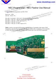
VTOOLSHOP<br />
Tel:+86-0755-27823977<br />
Web:http://www.v<strong>tool</strong>shop.com<br />
www.v<strong>tool</strong>shop.com<br />
MITSUBISHI MOTORS<br />
M.U.T.-III Owner’s <strong>Manual</strong><br />
Multi Use Tester<br />
< Ver. 7.0 ><br />
Heart-Beat Motors<br />
MITSUBISHI MOTORS
VTOOLSHOP<br />
Tel:+86-0755-27823977<br />
Web:http://www.v<strong>tool</strong>shop.com<br />
M.U.T.-III Owner's <strong>Manual</strong><br />
www.v<strong>tool</strong>shop.com<br />
Foreword<br />
This manual explains M.U.T.-III: functions, operating procedures, and other related information.<br />
By reading this manual you will obtain a basic understanding of M.U.T.-III and Vehicle<br />
Communication Interface (hereafter abbreviated as V.C.I.) functions and methods of operation.<br />
Because there are differences in M.U.T.-III methods of operation due to the vehicle electronic<br />
control system, be sure to read this manual and Online Help prior to operation.<br />
This manual was written based on the October 2006 version of the M.U.T.-III system.<br />
Please note that the information herein may not always agree with your version of the M.U.T.-III<br />
system due to system specification changes and version upgrades.<br />
Please take good care of this manual along with your M.U.T.-III product.
M.U.T.-III Owner's <strong>Manual</strong><br />
Table of Contents<br />
Chapter 1 Product Overview........................................................................................ 1<br />
1-1. Precautions...............................................................................................................................1<br />
1-2. V.C.I. Outline Drawing and Component Names........................................................................2<br />
1-3. M.U.T.-III Components Explanations ........................................................................................3<br />
1-4. Harness Connection Method ....................................................................................................5<br />
1-5. Combination Chart of Harness and Vehicle ..............................................................................6<br />
Chapter 2 M.U.T.-III Functions...................................................................................... 8<br />
2-1. Basic Functions ........................................................................................................................8<br />
2-2. V.C.I. Functions ........................................................................................................................9<br />
Chapter 3 Operating M.U.T.-III.....................................................................................11<br />
3-1. Starting and Shutting the M.U.T.-III System ........................................................................... 11<br />
3-2. Screen Explanations...............................................................................................................13<br />
3-3. Basic Flow to Start Diagnosis .................................................................................................15<br />
3-4. Option Settings .......................................................................................................................18<br />
3-5. Useful Functions.....................................................................................................................19<br />
Chapter 4 Diagnosis Function ................................................................................... 20<br />
4-1. Diagnostic Trouble Code ........................................................................................................20<br />
4-2. Data List (Service Data monitor).............................................................................................23<br />
4-3. Actuator Test...........................................................................................................................26<br />
4-4. V.C.I. Stand-alone Diagnosis ..................................................................................................29<br />
4-5. All DTCs..................................................................................................................................34<br />
Chapter 5 Special Function (Calibration & Setting)................................................. 37<br />
5-1. ECU Information .....................................................................................................................37<br />
5-2. Learned Value Reset ..............................................................................................................37<br />
5-3. Steering Angle Sensor Calibration ..........................................................................................38<br />
5-4. Lateral G Sensor Calibration ..................................................................................................40<br />
Chapter 6 Drive Recorder........................................................................................... 41<br />
6-1. How to Record the Data .........................................................................................................41<br />
6-2. Recorded Data Handling ........................................................................................................53<br />
6-3. Display and Analysis of the Recorded Data............................................................................58<br />
Chapter 7 SWS Monitor.............................................................................................. 64<br />
7-1. SWS Monitor Operation..........................................................................................................64<br />
Chapter 8 CAN Bus Diagnosis................................................................................... 73<br />
8-1. Diagnosing the CAN Bus ........................................................................................................73
M.U.T.-III Owner's <strong>Manual</strong><br />
Chapter 9 ECU Reprogramming ................................................................................ 74<br />
9-1. Process Flow Chart ................................................................................................................74<br />
9-2. Equipments.............................................................................................................................75<br />
9-3. Data preparation on PC from Update CD-ROM......................................................................76<br />
9-4. Reprogramming Operation ( V.C.I. alone )..............................................................................78<br />
9-5. Reprogramming Operation ( V.C.I. - PC connected )..............................................................85<br />
9-6. Reprogramming by CAN communication................................................................................89<br />
9-7. Troubleshooting of Reprogramming........................................................................................91<br />
Chapter 10 Measurement Functions ......................................................................... 95<br />
10-1. Injector-Type Fuel Consumption Measurement ....................................................................95<br />
10-2. Fuel pressure, Voltage, Ohmmeter, Oscilloscope .................................................................97<br />
Chapter 11 Troubleshooting Procedures................................................................ 100<br />
11-1. Individual Troubleshooting Procedures ...............................................................................100<br />
Chapter 12 Reference Material ................................................................................ 102<br />
12-1. V.C.I. Electrical Properties ..................................................................................................102<br />
Appendix ................................................................................................................... 103<br />
> .......................................................................................................................103<br />
> ..............................................................................................105
For Your Safety<br />
For Your Safety<br />
To ensure proper use of this product and prevent personal injury and property damage, various graphic<br />
displays are used in the user’s manual. The graphic displays and respective meanings are described<br />
below.<br />
Warning<br />
Warning messages alert you to a procedure or practice<br />
which, if not followed correctly, could lead to death or serious<br />
injury.<br />
Caution<br />
Caution messages alert you to a procedure or practice<br />
which, if not followed correctly, could lead to serious injury<br />
and/or property damage.<br />
Icon<br />
Examples<br />
The<br />
The<br />
symbol alerts you to a prohibited action.<br />
symbol alerts you to an action that must be enforced.<br />
Warning<br />
Drivers should not operate the unit while<br />
driving.<br />
• Operating the unit while driving may result in<br />
a traffic accident.<br />
Do not plug in or unplug the power AC adapter<br />
with wet hands.<br />
• Doing so results in the risk of electric shock.<br />
When using the cigarette lighter plug to supply<br />
power to the V.C.I. unit, be sure the power<br />
voltage supplied is DC32V or less.<br />
• Applying a voltage greater than DC32V<br />
results in the risk of fire.<br />
• M.U.T.-III as provided to dealers includes<br />
12V accessory / cigarette lighter plug<br />
adapter to power M.U.T.-III during extended<br />
test drives.<br />
Maximum voltage the V.C.I. can withstand is 40V.<br />
Do not use the V.C.I. on systems greater than the<br />
32-volt system mentioned previously.<br />
• Violating this requirement results in the risk of a<br />
ground fault, damage and/or electric shock.
For Your Safety<br />
Warning<br />
The V.C.I. screen is liquid crystal display or<br />
LCD. In the unlikely event that the display<br />
breaks due to impact, do not let your skin<br />
come in contact with the LCD fluid.<br />
• If your skin comes in contact with the LCD<br />
fluid, wash your skin thoroughly with water.<br />
If skin rash or abnormality occurs seek<br />
medical attention from a doctor.<br />
Be sure to hold the harness connector when<br />
disconnecting from the vehicle. Do not<br />
disconnect the harness by pulling on the cord.<br />
• Pulling the cord rather than the connector<br />
may result in damage to the lead wire inside<br />
the cord, thereby causing a short and<br />
possibly starting a fire.<br />
Do not use the unit if the power AC adapter plug<br />
or cord is damaged or plugging into the outlet is<br />
loose.<br />
• Use under such conditions may result in<br />
electric shock, an electric short and/or fire.<br />
Unplug the power AC adapter from the outlet<br />
when the unit is not in use.<br />
• Failure to do so may result in injury, burns,<br />
electric shock caused by insulation<br />
deterioration, or fire due to a short circuit.<br />
Warning<br />
When the harness is connected to the V.C.I., be sure to check the top and bottom of the<br />
connector and connect the harness perpendicularly to the connector of the V.C.I.<br />
Connecting at an angle may result in bending of the pins of the connector.<br />
Check for the secure connection of the harness before tightening of the screw locks.<br />
• The bent pin may contact the connector case, thereby causing an electric short which<br />
leads to damage to the V.C.I.
For Your Safety<br />
Please Note<br />
Do not expose the PC or V.C.I. to direct sunlight or high temperatures, or leave the unit in<br />
sun-heated cars. Such action may result in system failure.<br />
Store the PC and V.C.I. in a dry environment at room temperatures.<br />
Moving the PC and V.C.I. to a location with a very different temperature and humidity than that of<br />
the previous location may result in external or internal condensation. Caution is required.<br />
Protect the PC and V.C.I. from exposure to elements such as rain, dirt, dust, food and liquids.<br />
Be careful when handling the PC and V.C.I. Dropping the units may result in damage.<br />
Do not expose either unit to engine oil, gasoline, antifreeze or battery acid. Also, do not clean the<br />
PC or V.C.I. case using solutions such as thinner or benzene. Doing so may result in deterioration<br />
of the case surface.<br />
Prior to connecting the M.U.T.-III main harness between the V.C.I. and vehicle, turn the IG switch<br />
to OFF.<br />
• Connecting the V.C.I. harness with the IG switch ON may damage the V.C.I. programming.<br />
Use only the power AC adapter included with the PC (or approved replacement), power cigarette<br />
plug, other probes, main harness and other cables.<br />
• Use of unspecified parts may result in damage or malfunction due to excess voltage or<br />
insufficient contact.<br />
The LCD display of this unit turns off when the supplied voltage is less the DC 8V. This is not an<br />
error.<br />
The power supplied should be from 8VDC to 32VDC.<br />
Keep all V.C.I. connectors and openings away from dirt and static electricity. Exposure to dirt and<br />
static electricity may result in malfunction and damage.
Precautions<br />
Chapter 1 Product Overview<br />
1-1. Precautions<br />
Service Work Precautions<br />
• Be sure to follow all basic service work precautions when using M.U.T.-III during vehicle<br />
inspection and service work.<br />
• For detailed information regarding service work precautions, refer to the service instruction<br />
manual of each vehicle.<br />
Work Precautions<br />
• When performing vehicle inspection work at the work site with the engine running, either use an<br />
exhaust gas discharger or ventilate the area sufficiently.<br />
• When working on a vehicle, be sure to apply the parking brake and set wheel chocks in place to<br />
prevent the car from moving.<br />
Driving Precautions<br />
• If you wish to use M.U.T.-III while driving the target vehicle, first verify that all parts are properly<br />
assembled.<br />
• While driving, always have an assistant operate M.U.T.-III.<br />
• Be sure that the M.U.T.-III main harness and other cables will not interfere with driving.<br />
• Install and remove the PC and V.C.I. with the vehicle parked, IG switch OFF.<br />
PC Usage Limitations<br />
Do Not Install Software on the PC<br />
• The M.U.T.-III PC is a special service <strong>tool</strong>. Do not install any software other than M.U.T.-III<br />
software onto the unit. Installation of other software results in the risk of M.U.T.-III system<br />
failure.<br />
• Any unauthorized software will not be supported. Technical support for units with<br />
unauthorized software will be charged additional technical support fees to return the unit to its<br />
authorized state of operation.<br />
• All unauthorized software will be erased with each new upgrade.<br />
1
V.C.I. Outline Drawing and Component Names<br />
1-2. V.C.I. Outline Drawing and Component Names<br />
The names of the V.C.I. components are indicated in the figure below.<br />
I/F cartridges<br />
1<br />
3<br />
2 7<br />
M.U.T.-III main harness A (MB991910)<br />
4<br />
8<br />
9<br />
10<br />
M.U.T.-III main harness B (MB991911)<br />
M.U.T.-III main harness C (MB991914)<br />
(For US only)<br />
6<br />
5<br />
USB cable (MB991827)<br />
Measurement adapter (MB991825)<br />
Trigger harness (MB991826)<br />
(Not available in US)<br />
CF memory card<br />
& adapter<br />
(MB991939)<br />
(MB991853)<br />
<br />
1. I/F cartridge terminal<br />
2. LCD screen<br />
3. Indicator lamp<br />
4. Operation button<br />
(Used with V.C.I. functions)<br />
5. Memory card removal lever<br />
6. Memory card insertion port<br />
7. Power switch<br />
8. Main harness terminal<br />
9. USB terminal<br />
10. Trigger terminal<br />
2
M.U.T.-III Components Explanations<br />
1-3. M.U.T.-III Components Explanations<br />
(1) Vehicle Communication Interface (V.C.I.) (MB991824)<br />
A communication interface used to connect the vehicle<br />
ECUs and the PC.<br />
1. When connected with the PC<br />
• Vehicle diagnosis (Interactive fault diagnosis)<br />
• SWS communication & CAN communication support<br />
• Drive recorder<br />
• ECU reprogramming<br />
• Volt, Ohm, measurement<br />
• Fuel pressure measurement (Not available in US)<br />
2. When used with the V.C.I. unit (disconnected from PC)<br />
• V.C.I. Stand-alone diagnosis<br />
• Drive recorder<br />
• ECU reprogramming<br />
• Volt, Ohm measurement<br />
• Belt Tension measurement<br />
(2) Memory <strong>Car</strong>d<br />
Stores data for ECU reprogramming, drive recorder, etc.<br />
This is a standard, off-the-shelf memory card. The one<br />
provided (with reprogramming data) is a Compact Flash<br />
memory card (MB991853) inserted into the CF card adapter<br />
(MB991939).<br />
(3) M.U.T.-III Main Harness A (MB991910)<br />
Used when connecting the V.C.I. with vehicles that have<br />
only one 16-pin diagnosis connector.<br />
• Supports fault diagnosis and ECU updating on the<br />
above-described vehicles<br />
• Supports the CAN communication system<br />
(4) M.U.T.-III Main Harness B (MB991911)<br />
Used when connecting V.C.I. with vehicles that have a<br />
16-pin + 12-pin or 16-pin + 13-pin diagnosis connector.<br />
For models equipped with only 12-pin (or 12-pin + 12-pin)<br />
diagnosis connector, connect the M.U.T.-II adapter harness<br />
(MB991498) to the end of this harness in the same as<br />
M.U.T.-II, and power is supplied from the cigarette lighter<br />
socket.<br />
3
M.U.T.-III Components Explanations<br />
(5) M.U.T.-III Main Harness C (MB991914) (For US only)<br />
Used when connecting the V.C.I. with vehicles that have the<br />
420A engine and F4AC1 transaxle.<br />
(6) USB Cable (MB991827)<br />
Used to connect the PC to the V.C.I.<br />
(7) Trigger Harness (MB991826) (Not available in US)<br />
A harness with a trigger button used to manually insert a<br />
trigger point for data acquisition from the drive recorder<br />
function during data recording.<br />
(8) Measurement Adapter (MB991825)<br />
An adapter used to connect the V.C.I. and measurement<br />
probe for voltmeter and ohmmeter readings.<br />
Or used when outputting Simulated Vehicle Speed with a<br />
vehicle whose diagnosis-connecter cannot receive vehicle<br />
speed signal.<br />
(9) Measurement Test Leads (MB991499)<br />
Test leads used for voltage and / or resistance<br />
measurement.<br />
Test leads MB991499 acquire quality replacement test<br />
leads from Radio Shack or similar electronics stores.<br />
(10) I/F <strong>Car</strong>tridge<br />
Used to implement special functions that cannot be<br />
implemented with the V.C.I. unit alone. The following I/F<br />
cartridges used with M.U.T.-II can be used with M.U.T.-III as<br />
well:<br />
• SWS I/F cartridge<br />
• Daimler-Chrysler Corporate I/F cartridge<br />
4
Harness Connection Method<br />
1-4. Harness Connection Method<br />
Recommended harness connection sequence<br />
[1] Start the PC.<br />
[2] While the PC is starting, connect the USB cable to the V.C.I.<br />
[3] After the PC boots to the M.U.T.-III main screen, connect the USB cable to the PC.<br />
Note: Disconnect the USB cable from the V.C.I. after the PC has shut down. However, if the<br />
USB cable is disconnected during use, a warning message indicating device<br />
disconnection such as that shown in Figure 1 appears. Close the message display by<br />
pressing the OK button.<br />
[4] Select the appropriate M.U.T.-III main harness. Connect it to the V.C.I.<br />
[5] Connect the M.U.T.-III main harness to the vehicle diagnosis connector. See Figure 2.<br />
Note: Disconnect the harnesses by performing the above steps in the reverse order.<br />
[6] Turn the V.C.I. power switch ON and verify that the indicator lamp located in the upper right area<br />
of the LCD screen is green.<br />
[7] Turn the vehicle ignition switch ON, and begin the <strong>diagnostic</strong> process from the M.U.T.-III system<br />
screen.<br />
Note: In case the version of V.C.I. and the firmware version of V.C.I., which are mismatch, a<br />
dialog box appears on PC screen, and the V.C.I. version upgrade process begins. This<br />
upgrade typically only occurs once per M.U.T.-III system upgrade. Normal V.C.I.<br />
upgrades take about 1 minute. If a version upgrade error occurs, restart the V.C.I. by<br />
turning V.C.I. power OFF then, while pressing the Esc button, turn the V.C.I. power switch<br />
ON and begin the <strong>diagnostic</strong> process again.<br />
[6] [7]<br />
[1]<br />
[3] [2] [4] [5]<br />
<br />
<br />
<br />
<br />
Connect the trigger harness to the<br />
V.C.I. trigger terminal.<br />
(Not available in US)<br />
5<br />
Connect the measurement adapter to the V.C.I.<br />
trigger terminal. Insert the measurement leads to<br />
the adapter. For best results, match the test lead<br />
colors with those on the adapter.
Combination Chart of Harness and Vehicle<br />
1-5. Combination Chart of Harness and Vehicle<br />
Use of the M.U.T.-III main harness A, B or C (US only) is determined by the type of diagnosis<br />
connector installed in the vehicle.<br />
The main harness, indicated with “O”, is used in combination with another harness indicated with<br />
“!” depending on the vehicle and work to be performed. ECU update used below means ECU<br />
reprogramming.<br />
Vehicle<br />
Diagnosis<br />
Connector<br />
Harness Name<br />
Diagnostic<br />
Function<br />
01 02 03 04 05<br />
M.U.T.-III Main<br />
Harness A<br />
M.U.T.-III Main<br />
Harness B<br />
M.U.T.-III Main<br />
Harness C<br />
Conventional<br />
Vehicle Inspection<br />
Adapter Harness<br />
ECU Update<br />
Adapter Harness<br />
16Pin<br />
Fault diagnosis O<br />
ECU update O<br />
16Pin&12Pin<br />
Fault diagnosis O<br />
ECU update<br />
O<br />
12Pin<br />
Fault diagnosis O !<br />
ECU update - - - - -<br />
16Pin&13Pin<br />
Fault diagnosis O<br />
ECU update O !<br />
Vehicle with Fault diagnosis O<br />
420A Engine and<br />
F4AC1 Transaxle ECU update - - -<br />
Harness Name<br />
01 M.U.T.-III Main Harness A<br />
MB991910<br />
Illustration<br />
02 M.U.T.-III Main Harness B<br />
MB991911<br />
03 M.U.T.-III Main Harness C<br />
MB991914<br />
(For US only)<br />
04 Conventional Vehicle Inspection Adapter Harness<br />
(M.U.T.-II adapter harness)<br />
MB991498<br />
05 ECU Update Adapter Harness<br />
MB991855<br />
6
Combination Chart of Harness and Vehicle<br />
Vehicle <strong>diagnostic</strong> connector - 16pin type<br />
Main harness A<br />
(MB991910)<br />
to 16pin diagnosis connector<br />
Vehicle <strong>diagnostic</strong> connector - 16pin type + 12 pin type<br />
Main harness B<br />
(MB991911)<br />
to 12pin diagnosis connector<br />
to 16pin diagnosis connector<br />
Vehicle <strong>diagnostic</strong> connector - 12pin type<br />
to 12pin diagnosis connector<br />
to cigarette lighter<br />
Main harness B<br />
(MB991911)<br />
Conventional Vehicle Inspection Adapter harness<br />
(M.U.T.-II Adapter Harness)<br />
(MB991498)<br />
Vehicle <strong>diagnostic</strong> connector - 16pin type + 13 pin type<br />
to 13pin diagnosis connector<br />
to 16pin diagnosis connector<br />
Main harness B<br />
(MB991911)<br />
ECU update<br />
adapter harness<br />
(MB991855)<br />
7
Basic Functions<br />
Chapter 2 M.U.T.-III Functions<br />
2-1. Basic Functions<br />
Can be used with all vehicle installed electronic control systems (with built-in <strong>diagnostic</strong> functions)<br />
from model year 1984.<br />
Function<br />
DTC readout<br />
Data List<br />
Actuator tests<br />
Simulated<br />
vehicle speed<br />
Drive Recorder<br />
Voltmeter<br />
Ohmmeter<br />
SWS Diagnosis<br />
CAN Bus Diagnosis<br />
ECU Reprogramming<br />
Electronic service<br />
information<br />
Tension meter<br />
Fuel pressure meter<br />
Fuel consumption<br />
measurement<br />
Synopsis<br />
Reads various <strong>diagnostic</strong> codes and displays the codes by name and<br />
number.<br />
Reads RAM data inside ECU and displays the data in digital and graphic<br />
form. (Available with ECUs that support serial communication only)<br />
Permits forced operation or shutdown of various types of actuators that is<br />
required for service.<br />
(Available with ECUs that support serial communication only)<br />
Outputs vehicle speed signal to appropriate ECUs facilitating diagnosis<br />
without travel.<br />
Permits recording and displaying arbitrary service data that is determined<br />
for an arbitrarily specified time.<br />
Permits measurement of DC voltage within the range of 0- ±40V using<br />
the voltage measurement function.<br />
Permits measurement of resistance within the range of 0-100KΩ using<br />
the resistance measurement function.<br />
Permits SWS diagnosis using the SWS monitor kit (MB991806).<br />
Identifies CAN bus failures that occur in vehicle that is subject to the<br />
diagnosis and narrows down a cause.<br />
Permits updating programs in ECU for system version upgrade.<br />
Displays with Service manual data.<br />
In addition, the system supports interactive fault diagnosis. The Interactive<br />
Diagnosis permits user to use both the scan <strong>tool</strong> viewing functions and<br />
service manual troubleshooting procedures.<br />
(Not available in US and Australia)<br />
Permits measurement of belt tension using Belt tension meter set<br />
(MB991668).<br />
Permits measurement of fuel pressure using a pressure gauge set<br />
(MB991637 / MB991981), and displays it on PC. (Not available in US)<br />
Permits more precise measurement of fuel consumption by measuring<br />
injection quantity of fuel injector.<br />
8
V.C.I. Functions<br />
2-2. V.C.I. Functions<br />
<br />
2-2-1. Fault Diagnosis<br />
The system diagnoses faults by receiving instructions from<br />
the PC and communicating with the vehicle-installed ECU.<br />
When the system is connected to the PC, V.C.I. keys are<br />
disabled.<br />
[Start Screen]<br />
*When the USB cable is connected to the system, the<br />
screen illustrated on the left appears.<br />
The screen indicates the flow of signals between the PC (P)<br />
and V.C.I. (V) using “P " V” and “P # V”.<br />
2-2-2. Fuel Pressure measurement (Not available in US)<br />
The system analyzes faults by measuring fuel pressure<br />
using the Pressure gauge set (MB991637 or MB991981).<br />
Pressure gauge for LP: MB991655 or MB991979<br />
for HP: MB991708 or MB992007<br />
The V.C.I. reads the fuel pressure, which is converted into<br />
voltage value by the pressure gauge. Then the system<br />
converts it back to pressure value and displays it as text or<br />
graph on PC screen. (refer to 10-2-1.)<br />
<br />
2-2-3. Measurement Function - Voltmeter / Ohmmeter<br />
The system reads the voltage/resistance value from the trigger<br />
terminal and displays the value on the V.C.I. LCD screen.<br />
1. Connect the measurement adapter to the V.C.I., connect the<br />
test leads to the adapter.<br />
2. Connect the appropriate main harness to the V.C.I., and then<br />
to the vehicle <strong>diagnostic</strong> leak connector and turn the V.C.I.<br />
power switch ON.<br />
3. Press button to select Voltmeter or Ohmmeter in the<br />
Main Menu (see the illustration on the left), and press the<br />
(Enter) button to begin measurement.<br />
Note:<br />
• Permits measurement of DC voltage within the range of 0-<br />
±40V.<br />
• Permits measurement of resistance within the range of<br />
0-100KΩ.<br />
• Permits displaying the value as text or graph on PC<br />
screen by connecting the V.C.I. to PC. (refer to 10-2-2.)<br />
9
V.C.I. Functions<br />
2-2-4. V.C.I. Stand-alone Diagnosis<br />
You can read out DTCs with V.C.I. stand-alone by using a<br />
memory card, which is storing a <strong>diagnostic</strong> data transferred<br />
from PC. There is no need to carry PC or USB cable on the<br />
diagnosing vehicle. (For detailed operation, see 4-4)<br />
1. Transfer the <strong>diagnostic</strong> database file into a memory card.<br />
(4-4-1)<br />
2. Insert the memory card into V.C.I., then connect the V.C.I.<br />
and the vehicle with an appropriate main harness.<br />
3. Start reading out DTCs from vehicle-installed ECU by V.C.I.<br />
stand-alone. (4-4-2)<br />
Note:<br />
Until a new database file will be distributed, you do not have to<br />
operate above step1. Please proceed just step2 and 3.<br />
10
Starting and Shutting the M.U.T.-III System<br />
Chapter 3 Operating M.U.T.-III<br />
3-1. Starting and Shutting the M.U.T.-III System<br />
[Starting the PC]<br />
3-1-1. Starting the M.U.T.-III System<br />
1. Please turn on the power of M.U.T.-III PC.<br />
(Refer to the instructions of M.U.T.-III PC for<br />
details.)<br />
[To start up M.U.T.-III System]<br />
2. Double-click the M.U.T.-III icon displayed on the<br />
desktop to start up the system.<br />
[M.U.T.-III icon]<br />
Trademarks<br />
• Microsoft®, Windows 2000® and Internet Explorer® are trademarks or registered trademarks of<br />
Microsoft Corporation in the United States and/or other countries.<br />
• Adobe, the Adobe logo, Adobe Acrobat and the Adobe Acrobat logo are trademarks of Adobe<br />
Systems Incorporated.<br />
11
Starting and Shutting the M.U.T.-III System<br />
[Close the M.U.T.-III System]<br />
3-1-2. Shutting Down the M.U.T.-III System<br />
1. Press button on each <strong>diagnostic</strong> screen to return to the<br />
STV Top Menu screen (illustrated on the left).<br />
Then press button on this screen to go to the M.U.T.-III<br />
Start screen.<br />
2. Press Exit button displayed on the lower right portion of<br />
the M.U.T.-III Start screen. M.U.T.-III system will close.<br />
[Shutting down the PC]<br />
3. Click the Windows Start button (lower left portion of the<br />
screen), and select “Shut Down”.<br />
4. Select “Shut down” from the pull-down menu, and press the<br />
OK button.<br />
12
Screen Explanations<br />
3-2. Screen Explanations<br />
< M.U.T.-III Start Screen ><br />
Starts “Scan Tool Viewer (STV)” system.<br />
This manual contains information for<br />
proper operation of this system.<br />
Press this button first to start various<br />
interactive diagnoses.<br />
Exits the M.U.T.-III system.<br />
(refer to 3-1-2.)<br />
Shows “M.U.T.-III Owner’s <strong>Manual</strong>”.<br />
(refer to 3-5-2.)<br />
To set option settings, e.g. displaying<br />
language. (refer to 3-4.)<br />
Starts “Service <strong>Manual</strong> Viewer (SMV)”.<br />
For detailed operation procedure,<br />
click the SMV MANUAL bookmark<br />
on the left screen of Adobe Reader.<br />
< STV Top Menu ><br />
To diagnose vehicles by selecting<br />
each system (ECU).<br />
e.g.<br />
-Reading <strong>diagnostic</strong> trouble code<br />
-Actuator test -Drive recorder<br />
For detailed operation procedure,<br />
refer to 3-3-1.<br />
Starts the CAN bus diagnosis.<br />
refer to Chapter 8.<br />
-To display saved data<br />
(Drive recorder, SWS monitor)<br />
-V.C.I. Stand-alone Diagnosis (4-4)<br />
-All DTCs Function (4-5)<br />
-ECU reprogramming (Chapter 9)<br />
-Measurement Function (Chapter 10)<br />
13
Screen Explanations<br />
< System Selection Screen ><br />
This screen is for specifying a system that<br />
you want to diagnose.<br />
As operation procedure differs according<br />
to the vehicle’s Model Year, please select<br />
“Up to 2005MY” (2004MY in EU) or “From<br />
2006MY” (2005MY in EU) firstly.<br />
(refer to 3-3-1)<br />
<br />
The Special Function selection screen<br />
allows you to switch between major<br />
categories by selecting the tabs<br />
located on the upper part of the screen.<br />
<br />
The <strong>diagnostic</strong> screen displays three<br />
titles in layer format, informing you<br />
what is being implemented on each<br />
system. The screen does not allow<br />
you to switch systems by selecting<br />
the upper title areas.<br />
14
Basic Flow to Start Diagnosis<br />
3-3. Basic Flow to Start Diagnosis<br />
3-3-1. Basic Flow of System Select Diagnosis<br />
(1) M.U.T.-III Start Screen<br />
Press STV (Scan Tool Viewer)<br />
Start Screen.<br />
button on the M.U.T.-III<br />
(2) STV Top Menu<br />
Press System Select<br />
button on the STV Top Menu screen.<br />
(3) System Selection Screen<br />
Select either one of “Up to 2005MY” or “From 2006MY” for<br />
the Model Year of the vehicle you are diagnosing.<br />
Then follow the each operation below.<br />
*a<br />
$ When selecting “Up to 2005 MY”<br />
1. Select a system on the System List (*a), and press .<br />
2. If the system has a loading option, the Loading Option<br />
Setup list (*b) will be displayed. Then, select an item<br />
having a box checked ( ) and press button.<br />
*a<br />
*b<br />
*c<br />
$ When selecting “From 2006 MY”<br />
1. Confirm the contents of the Vehicle Information list (*c).<br />
-When the contents are not describing the vehicle, press<br />
to correct the information. (For details, refer to 3-3-2)<br />
Note:<br />
M.U.T.-III for EU countries, the options<br />
for Model Year is classified in<br />
“Up to 2004 MY” and “From 2005 MY”.<br />
2. Select a system on the System List (*a), and if the Loading<br />
Option Setup list (*b) is displayed, select an item having a<br />
box checked ( ). Then press button.<br />
15
Basic Flow to Start Diagnosis<br />
(4) Function Selection Screen<br />
After System selection, the Function selection menu of the<br />
selected system appears. Select a button that you want to<br />
perform.<br />
In the picture on the left shows the screen appears when the<br />
MPI/GDI/DIESEL system, which is a representative example,<br />
is selected. Details of each buttons are as follows.<br />
[MPI/GDI/DIESEL ‘s Function Selection menu]<br />
Note:<br />
As available functions differ between systems, there might be<br />
functions that will not appear when you select other system.<br />
Check Chart For Problem Symptoms -- To view the Symptom Chart of Service <strong>Manual</strong>.<br />
Self-diagnosis -- To read out or erase Diagnosis Trouble Codes from vehicle ECU.<br />
Also, you can read out the Freeze Frame data. (refer to 4-1.)<br />
Simulated Vehicle Speed Output --To transmit simulated vehicle speed signal into the vehicle.<br />
Data List -- To read the RAM data inside the ECU and displays the data in digital and graphic form.<br />
(refer to 4-2.)<br />
Actuator Test -- To control the ECU output device. (refer to 4-3.)<br />
Drive Recorder -- To record, display or analyze the ECU input / output signals which can be viewed<br />
using Data List function. (refer to Chapter 6)<br />
Special Function -- To execute special functions specific to the selected system. For detailed<br />
operation other than Chapter 5, please utilize each Online Help function.<br />
OBD-II Test Mode -- To read out “Monitoring test results” “Provisional DTC” and “ECU information”,<br />
which are regarding Emission Related System, from ECU.<br />
Readiness Test -- To read out the result of Readiness Test from ECU.<br />
Voltmeter -- To measure voltage value using M.U.T.-III. (same operation as 10-2-2)<br />
Ohmmeter -- To measure resistance value using M.U.T.-III. (same operation as 10-2-2)<br />
Fuel Pressure Gauge -- To measure fuel pressure using a pressure gauge, and display the result<br />
on PC screen. (Not Available in US)<br />
Check Mode – To shorten sampling time of communication by changing the communication method<br />
between M.U.T.-III and ECU. This function is available in Data List, Drive Recorder<br />
and Actuator Test.<br />
Emission Test -- To test the Evaporative Emission Control System of the vehicle.<br />
Coding -- To write the vehicle equipment specifications into ECU.<br />
SWS monitor (appears only when selecting “SWS” system) (refer to Chapter 7)<br />
Pulse Check<br />
(appears only when selecting “SWS” system)<br />
-- To confirm existence of the signal pulse to operate remote system on SWS<br />
communication line.<br />
16
Basic Flow to Start Diagnosis<br />
3-3-2. Vehicle Information Setting<br />
Pressing button, on System Selection Screen or other<br />
vehicle-confirmation screen, displays the Vehicle Information<br />
Setting Screen. This screen allows you to modify the<br />
diagnosing vehicle information.<br />
(1) Vehicle Information Setting Screen<br />
-Currently selected information is displayed in each item’s<br />
field. (Blank space means the information is not selected.)<br />
- DESTIN , TYPE , CLASS and MODEL YEAR are<br />
compulsory input.<br />
--OK (Returns to the screen on which was pressed)<br />
--Deletes whole information<br />
--Displays history of settings as open options.<br />
Press an item button to modify. -- to (2)<br />
(2) The item’s individual selection screen appears.<br />
Apply appropriate information, then press button to<br />
return to the Vehicle Information Setting screen (1).<br />
17
Option Settings<br />
3-4. Option Settings<br />
3-4-1. Edit Option Settings<br />
(1) Press Maintenance button on the lower portion of the<br />
M.U.T.-III Start Screen.<br />
[ Environment ]<br />
[ Data Update ]<br />
(2) Select a button corresponding to your purpose.<br />
[ Environment ]<br />
Change Environmental setting -- To set the driver, which<br />
the Service manual data should be installed.<br />
Show environmental setting -- To view the settings.<br />
Unit set -- To select US unit or metric unit, e.g. lbs : kg<br />
Printer set -- To set output conditions of the printer. (3-4-2.)<br />
Keyboard set -- To select row of keys: Alphabetical-order or<br />
QWERTY.<br />
Select Language for display -- To select a language<br />
displayed in whole M.U.T.-III system and Service manuals.<br />
(Service manual will not be displayed unless the selected<br />
language has been downloaded.)<br />
[ Data Update ]<br />
System Information -- To view versions of installed software<br />
on the PC.<br />
3-4-2. Set up Output conditions of Printer<br />
(1) When pressing the Printer set button on 3-4-1(2), the<br />
“Printer” window illustrated on the left appears.<br />
Select an appropriate printer icon and right-click it to open a<br />
pull-down menu; select “Printing Preferences…”.<br />
Note<br />
-Set up conditions on this window will not be reflected.<br />
(2) The “Printing Preferences” window of the selected printer<br />
appears. Please set output conditions e.g. page setup, and<br />
press OK button.<br />
18
Useful Functions<br />
3-5. Useful Functions<br />
3-5-1. Online Help Function<br />
(1) The button on each screen is the online help button for<br />
that screen.<br />
(2) The online help function allows you to view a general<br />
overview of each screen and refer to explanations of the<br />
various button functions. If you wish to move the screen up or<br />
down, select the applicable scroll button located on the right<br />
side of the screen.<br />
3-5-2. Display “M.U.T.-III Owner’s <strong>Manual</strong>”<br />
Press M.U.T.-3 <strong>Manual</strong> button at the lower-left portion of<br />
the M.U.T.-III Start Screen, then this Adobe Acrobat Reader<br />
“M.U.T.-III Owner’s <strong>Manual</strong>” starts.<br />
& Select “Bookmarks” tab at far left of the window.<br />
-When you select a title on the left column, you can jump into<br />
the corresponding page.<br />
-When you click , it turns to , and titles in lower layer are<br />
displayed.<br />
& Select “Pages” tab at far left of the window, then miniature<br />
version of pages are displayed on the left column. It shows<br />
currently displayed page with red frame so that you can see<br />
where the page is.<br />
Taskbar<br />
& Selecting M.U.T.-III system or “Adobe Reader” appearing as<br />
buttons on the Taskbar switches between the system and the<br />
manual. You can hereby readily check this manual while<br />
operating M.U.T.-III system.<br />
19
Diagnostic Trouble Code<br />
Chapter 4 Diagnosis Function<br />
4-1. Diagnostic Trouble Code<br />
4-1-1. Reading and Erasing Diagnostic Trouble Code (DTC)<br />
(1) Select a system that you want to diagnose on the System<br />
Selection screen. (For instruction on how to select a system,<br />
refer to 3-3-1)<br />
- In the explanation that follows, the method is explained<br />
using the MPI/GDI/Diesel system as a representative<br />
example.<br />
Note:<br />
If the engine is OBD, a check code appears.<br />
(2) Press Self-diagnosis button.<br />
The system automatically communicates with the vehicle<br />
ECU and obtains the <strong>diagnostic</strong> trouble codes (DTCs).<br />
(3) Diagnostic trouble codes (DTCs) of the selected system,<br />
which is currently stored in the vehicle ECU, are listed.<br />
DTC Procedures From Service <strong>Manual</strong><br />
--Switches the mode to interactive fault diagnosis mode.<br />
(refer to 4-1-2)<br />
(Not Available in US, Australia)<br />
Change Sensitivity --Allows you to increase the<br />
<strong>diagnostic</strong> code detection capability of the ECU or return<br />
the sensitivity level back to normal.<br />
Erase DTCs<br />
Freeze Frame Data<br />
--Deletes the <strong>diagnostic</strong> trouble codes.<br />
--Displays the Freeze frame data.<br />
20
Diagnostic Trouble Code<br />
4-1-2. Interactive Fault Diagnosis Mode<br />
(1) Press DTC Procedures From Service <strong>Manual</strong> button.<br />
Note:<br />
It is not necessary to select DTC code to be diagnosed..<br />
(2) Vehicle Information Setting Screen<br />
-Currently selected information is displayed in each item’s<br />
field. (Blank space means the information is not selected.)<br />
- TYPE , CLASS and MODEL YEAR are compulsory<br />
input.<br />
--OK<br />
--Deletes whole information<br />
--Displays history of settings as open options.<br />
Note:<br />
In case you want to be Interactive diagnosis mode,<br />
Workshop <strong>Manual</strong> data has to be installed into PC..<br />
(3) Diagnosis codes chart Screen<br />
Diagnosis codes of the selected vehicle are displayed.<br />
In order to diagnose for current DTC, press button to<br />
start troubleshooting.<br />
(4) Workshop <strong>Manual</strong> data of the selected DTC will be<br />
displayed.<br />
Proceed in accordance with displayed procedure on<br />
Workshop <strong>Manual</strong>, press button or button<br />
to go to next step.<br />
Press<br />
button to scroll the screen up and<br />
down, left and right movements.<br />
When you finished your operation, press button<br />
lower-left of the screen to close Workshop <strong>Manual</strong> screen.<br />
On the Workshop <strong>Manual</strong> screen, another Workshop<br />
<strong>Manual</strong>s can also be started up by pressing button.<br />
As it enables to browse multiple Workshop <strong>Manual</strong>s, so it is<br />
possible what Wiring diagram can be browsed while doing<br />
diagnosis each DTC. -- to (5)<br />
21
Diagnostic Trouble Code<br />
(5) Workshop <strong>Manual</strong> select screen<br />
Select manual to be browsed.<br />
Note:<br />
Vehicle Information button is not activated.<br />
(6) Shift of Workshop <strong>Manual</strong><br />
Select content you want from Workshop <strong>Manual</strong>s displayed<br />
on the task-bar button of the screen.<br />
Note:<br />
Workshop <strong>Manual</strong> in different kind of vehicles cannot be<br />
browsed simultaneously.<br />
(7) On Workshop <strong>Manual</strong> Viewer<br />
SMV that would be started up for the first time is called<br />
SMV(Main), and others are called SMV(Sub).<br />
- When SMV(Main) will be closed by button, other<br />
SMV(Sub) will be also closed altogether.<br />
- Each Workshop <strong>Manual</strong>(Sub) can be closed individually.<br />
- Select content you want from Workshop <strong>Manual</strong>s displayed<br />
on the task-bar bottom of the screen.<br />
22
Data List<br />
4-2. Data List (Service Data monitor)<br />
4-2-1. Display of Data List<br />
(1) Displaying Text style<br />
Press Data List button on the screen 4-1-1(2), and the<br />
left screen will be displayed.<br />
-- Select item -- to 4-2-2(1).<br />
-- 4items/4Graphs display -- to (2)<br />
-- 4items/View Graph (overwrite) -- to (3)<br />
-- Displays “Data List Reference Table”<br />
of Service <strong>Manual</strong> to view normal value.<br />
(Not available in US and Australia)<br />
(2) Displaying Graphs 1<br />
The graph screen displays the data of 4items/4graphs.<br />
-- 4items/4Graphs display<br />
-- 4items/View Graph (overwrite)<br />
-- View Text<br />
-- View1/2<br />
-- Change Time Scale<br />
-- Change Data Scale<br />
-- Pause -- to 4-2-2(2)<br />
-- Start<br />
-- View2/2<br />
Note:<br />
Record Data ( button allows you to save the portion of<br />
Data List displayed on the graph)-- refer to 4-2-2(2)<br />
(3) Displaying Graphs 2<br />
The data of displayed items are overlaid on a graph.<br />
Available function buttons are the same as Graph 1.<br />
23
Data List<br />
4-2-2. Details of Data List Screen<br />
(1) Displaying Item Selection<br />
• Item Group Select<br />
Select a group of the data to be displayed,<br />
and press button.<br />
• Item Select<br />
By default, none of the items are selected.<br />
Select an item that you wish to display, and apply the<br />
selection using or buttons.<br />
--Inserts all the items from “Available item list” into the<br />
selection areas of “Selected item list.”<br />
--Inserts the item selected in “Available item list” into the<br />
selection area of “Selected item list”.<br />
--Inserts the item selected in “Selected item list” into the<br />
lowermost area of “Available item list”.<br />
--Inserts all the items from “Selected item list” into the<br />
lowermost areas of “Available item list.”<br />
--Changes the order in which the items are displayed in<br />
the “Selected item list” and the “Available item list,” in<br />
the sequence of default setting.<br />
When complete the selection, press<br />
button.<br />
Note:<br />
-When there is no selected item, all items are displayed.<br />
-The column of item No appears in green when the service<br />
data is OBD basic items.<br />
-“Fuel pressure” and “Voltmeter” cannot be selected<br />
simultaneously.<br />
When you select the item “Fuel pressure”<br />
1. Pressure gauge list will be displayed after item selection.<br />
Select a type of pressure gauge used for fuel pressure<br />
measurement, and press button.<br />
2. Set up the calibration voltage of the pressure gauge, and<br />
press button.<br />
Note:<br />
For details on how to measure calibration voltage, refer<br />
to 10-2-1(1).<br />
24
Data List<br />
(2) Record Data<br />
1. Graph data is paused by pressing button, and the<br />
data can be saved on the PC automatically.<br />
-- OK -- to 2<br />
--Cancel (Not save the data and return to the pause<br />
screen. Pressing button starts data list again.)<br />
2. The data has been saved.<br />
The file name of the recorded data is set as<br />
”SD + YearMonthDay + Time (military time including<br />
seconds)”, using the PC time as standard.<br />
-- OK<br />
Note:<br />
For details on how to view the saved data, refer to 6-2-2(3).<br />
(3) Changing Item Display Order<br />
-On the data list display screen, you can change the display<br />
order of the items. The change is possible for both text<br />
display and graph display.<br />
-The display order change can be performed with the data<br />
list displayed continuously. (The graph display is reset.)<br />
-Selecting the name display area of an item fixes the item.<br />
Then over-scrolling only the items not selected using the<br />
vertical scroll keys changes the order.<br />
-The selection can be released by selecting the item again.<br />
-The function is not activated while a data range display<br />
area is selected. (Selection, release, and scroll functions of<br />
item are not available.)<br />
(4) Data Range Change<br />
-Select a data range display area on the graph.<br />
-When the color of the selected area turns into yellow, you<br />
can enter values.<br />
-Entering method: Use PC keyboard or scroll keys.<br />
-When use PC keyboard, enter a value, and then press the<br />
[Enter] key or release the selection of the data range<br />
display area to determine the data range change.<br />
-When the scroll keys, and , on the screen are used<br />
for the data range change, pressing the key each time<br />
changes the data range setting by +5 % of full scale and<br />
the . key changes it by −5 %. The change is determined<br />
at each key pressing.<br />
25
Actuator Test<br />
4-3. Actuator Test<br />
Press Actuator Test button on the screen 4-1-1.(2), then go to 4-3-1 or 4-3-2 to proceed,<br />
according to the type of the screen, A or B.<br />
4-3-1. Actuator Test (Type A)<br />
If the screen illustrated on the left appears….<br />
(1) Select a test item and press button to activate actuator.<br />
--Displays “Actuator test Reference Table” of Service<br />
<strong>Manual</strong>. (Not Available in US, Australia)<br />
--Data List simultaneous display (Text)<br />
--Data List simultaneous display (Graphs)<br />
(2) Actuator Test Executing<br />
If you want to interrupt Actuator Test, press<br />
button.<br />
When completes the test, a dialog box appears.<br />
Press button. " returns to screen (1).<br />
& Data List simultaneous display (Text)<br />
Refer to (1)(2).<br />
--Select items for Data list display<br />
(For details how to select items, refer to 4-2-2 (1).)<br />
& Data List simultaneous display (Graphs)<br />
Refer to (1)(2).<br />
--Select items for Data list display<br />
(For details how to select items, refer to 4-2-2 (1).)<br />
--Change Time Scale<br />
--Change Data Scale<br />
26
Actuator Test<br />
4-3-2. Actuator Test (Type B)<br />
If the screen illustrated on (2) or (3) appears….<br />
(1) Press button located next to item name, and select a test<br />
item from the pull-down menu.<br />
-When the selected item has no parameters -- to (2)<br />
-When the selected item has parameters -- to (3)<br />
--Displays “Actuator Test Reference Table” of<br />
Service manual.<br />
--Data List simultaneous display (Text)<br />
--Data List simultaneous display (Graphs)<br />
(2) Press button to execute Actuator Test. -- to (4)<br />
In case selected item has no parameter<br />
(3) The test item that you have selected need to be set some<br />
parameters. After completes the parameter setting, press<br />
button to execute the Actuator Test. -- to (4)<br />
*<br />
* “--Select the Value--” : Select the value from the pull-down.<br />
* “--Input the Value--” : Input the value using hexadecimal keys<br />
appeared by clicking the input box.<br />
In case selected item has parameters<br />
(4) Confirmation dialog box appears.<br />
Press button<br />
27
Actuator Test<br />
(5) Actuator Test Executing<br />
If you want to interrupt the Actuator Test, press<br />
button.<br />
When completes the test, a dialog box appears.<br />
Press button. " returns to screen (2) or (3).<br />
& Data List simultaneous display (Text)<br />
Refer to (1)-(5).<br />
--Select items for Data list display<br />
& Data List simultaneous display (Graphs)<br />
Refer to (1)-(5).<br />
--Select items for Data list display<br />
--Change Time Scale<br />
--Change Data Scale<br />
28
V.C.I. Stand-alone Diagnosis<br />
4-4. V.C.I. Stand-alone Diagnosis<br />
This function allows you to read out DTCs by V.C.I. alone, without carrying PC or USB cable into<br />
the vehicle, using a memory card that is storing a <strong>diagnostic</strong> data transferred from PC.<br />
Once 4-4-1 has been performed, you should precede just 4-4-2 operations until a new database<br />
will be distributed.<br />
4-4-1. Data transfer to memory card<br />
Transfers the data in hard drive to a memory card.<br />
Please perform this operation after every update of the<br />
database for V.C.I. stand-alone diagnosis.<br />
(1) Insert the memory card (MB991853) into the card adaptor<br />
(MB991939), and then insert them into m-card slot on PC.<br />
Note:<br />
If you use the same memory-card as using for ECU<br />
reprogramming, it may take time to display the next step after<br />
selecting [1.Read DTCs] on V.C.I. LCD menu. (refer to<br />
4-4-2(2)).<br />
(2) Press Special Function button on the STV Top Menu.<br />
(3) Select System Function tab,<br />
then press V.C.I. Stand-alone Diagnosis button.<br />
(4) The version of current data for V.C.I. Stand-alone Diagnosis<br />
is indicated on the left table.<br />
Please select a destination having a box checked ( ) on<br />
the right table, then press button to transfer the data.<br />
29
V.C.I. Stand-alone Diagnosis<br />
(5) Drive Selection<br />
Select the appropriate drive (removable disk drive) to save<br />
the data, then press button.<br />
(6) The data has been saved.<br />
Press button.<br />
(7) Before you remove the memory card, double-click the icon<br />
for removal of adaptor displayed on the bottom-right corner.<br />
Double click here<br />
(8) Select [PCMCIA IDE/ATAPI Controller] or the other<br />
appropriate device, then press Stop button.<br />
(9) Verify the contents of the selection, then press OK button.<br />
(10) After displayed the message “The device can now be safely<br />
removed from the system”, push the lever on the side of PC<br />
m-card slot and remove the memory card.<br />
Caution:<br />
Do not remove the memory card away unless complete<br />
above method or turn off the PC.<br />
30
V.C.I. Stand-alone Diagnosis<br />
4-4-2. Reading DTCs by V.C.I. stand-alone<br />
Connect with Main harness A or B<br />
(1) Insert the memory card, which is storing V.C.I. stand-alone<br />
diagnosis data, into the card adaptor, then insert them into<br />
V.C.I. main unit.<br />
-Connect the V.C.I. main unit and the diagnosing vehicle<br />
with an appropriate main harness securely.<br />
<br />
1 Read DTCs<br />
2 ECU Reprogram<br />
3 Voltmeter<br />
4 Ohmmeter<br />
(2) Turn the V.C.I. power ON, and the V.C.I. LCD screen<br />
displays the Main Menu as illustrated on the left.<br />
Confirm that “1. Read DTCs” is displayed, then press<br />
(Enter) button.<br />
Note:<br />
-If the memory card stores no data, the above Main Menu<br />
will not be displayed.<br />
-If the V.C.I. is set on Drive Recorder mode, the LCD<br />
displays Drive Recorder menu screen (refer to 6-1-1(18)).<br />
Please cancel the Drive recorder mode.<br />
<br />
Up to 2005MY<br />
From 2006MY<br />
For EU countries, the options are<br />
classified in “Up to 2004 MY”<br />
and “From 2005 MY”.<br />
Display Example:<br />
<br />
OUTLANDER(CW0#)<br />
・<br />
<br />
Z26A<br />
・<br />
<br />
XNLHL6<br />
・<br />
<br />
2006<br />
・<br />
Press Enter button<br />
Press Enter button<br />
Press Enter button<br />
Press Enter button<br />
(3) Press button to browse the list until the LCD displays<br />
the appropriate category for the vehicle you are diagnosing,<br />
then press (Enter) button.<br />
-When selecting “Up to 2005 MY” -- go to (5)<br />
-When selecting “From 2006 MY” -- go to (4)<br />
Note: <br />
- The display scrolls in the direction of the arrow displayed<br />
on the first line. To switch the direction, press (Esc)<br />
button once.<br />
- If you press (Esc) button twice in quick succession,<br />
the screen goes back to the Main Menu.<br />
(4) As next ‘Vehicle Select’ menu is displayed, press button<br />
to browse the list until the LCD displays the vehicle name,<br />
then press (Enter) button.<br />
After vehicle selection, the LCD menu is followed by ‘Model<br />
Select’, ‘Series Select’, and ‘Model Year Select’. Perform<br />
each selection in the same operation. " go to (6)<br />
Note:<br />
-The options are displayed in alphabetical order.<br />
31
V.C.I. Stand-alone Diagnosis<br />
Display Example:<br />
<br />
MPI/GDI/DIESEL<br />
IMMOBILIZER<br />
ELC-AT/CVT<br />
ABS/ASC/ASTC<br />
TCL<br />
・<br />
(5) System Selection<br />
Press button to browse the list until the LCD displays<br />
the system you want to diagnose, then press (Enter)<br />
button.<br />
Display Example:<br />
<br />
ABS<br />
ASC<br />
(6) Option Selection<br />
If the system has a loading option, the ‘Option Select’ menu<br />
will be displayed. (If not, go to (7) directly)<br />
Select an option, then press (Enter) button.<br />
Display Example:<br />
01/10<br />
C1234 RL Weel Sp<br />
C xxxx * Pump Motor<br />
C xxxx Brake Peda<br />
U xxxx * Bus off<br />
・<br />
RL Weel Speed Sen<br />
sor Short Circuit<br />
(7) Display of the DTCs<br />
The DTCs that have been read from ECU are displayed.<br />
-The number shown on the right edge of first line is<br />
indicating [Serial # / Total number of detected DTCs].<br />
-Press button to display the next DTC.<br />
(When having only one DTC, the arrow is not displayed<br />
on the first line.)<br />
-V.C.I. is constantly reading DTCs and updating the display.<br />
-If the system supports status recognition, current status of<br />
each DTC is expressed by the following symbols, which<br />
appears between code and name.<br />
Active : [ ] (blank)<br />
Stored : [ * ]<br />
Pending : [ # ]<br />
-Pressing (Enter) button shows full name of the DTC.<br />
(To return to the previous screen, press or once.)<br />
NOTE:<br />
The following systems, which need special process to read DTCs, are out of target for the<br />
V.C.I. Stand-alone diagnosis.<br />
-Some of ABS for MIRAGE / LANCER(CMO/CLO#)<br />
-SWS for GRANDIS(NA4W) / COLT(Z20#)<br />
32
V.C.I. Stand-alone Diagnosis<br />
4-4-3. Troubleshooting of V.C.I. Stand-alone Diagnosis<br />
No. Message Cause/Remedy<br />
1<br />
<br />
Check PC <strong>Car</strong>d<br />
<br />
Failed to access the memory card.<br />
<br />
1. Verify that the memory card is inserted into PC correctly.<br />
2. Press the V.C.I. “Enter” key to go back to the Main menu, then<br />
start the operations over again.<br />
2 Current Ver<br />
Program: **.**<br />
Database: **.**<br />
3<br />
<br />
Update Diag.data<br />
<br />
Check the system<br />
<br />
The V.C.I. stand-alone diag. database stored in memory card<br />
does not work with the V.C.I. built-in program for V.C.I.<br />
stand-alone diag.<br />
<br />
1. Press the V.C.I. “Enter” key to go back to the Main menu.<br />
2. Remove the memory card, then insert it into PC to update the<br />
database.(refer to 4-4-1)<br />
3. If the database is the latest one, connect PC and V.C.I. to<br />
update the V.C.I. built-in program.<br />
4. Start the operations over again.<br />
<br />
Failed to initialize ECU by any cause.<br />
<br />
1. Confirm that the system option that you selected is installed in<br />
the vehicle.<br />
2. Check if the communication wire between V.C.I and ECU is<br />
breaking or not.<br />
3. Verify that proper main harness is connected.<br />
4. Press the V.C.I. “Enter” key, then restart the procedures from<br />
system selection operation. (4-4-2(5))<br />
* Check the battery voltage of the diagnosing vehicle.<br />
4<br />
5<br />
6<br />
<br />
Check the system<br />
<br />
Update Diag. data<br />
<br />
Retry?<br />
<br />
Failed to read out DTCs.<br />
<br />
1. Confirm that the system option that you selected is correct.<br />
2. Press the V.C.I. “Enter” key, then restart the procedures from<br />
system selection. (4-4-2(5))<br />
<br />
The information read from ECU is not registered in the database.<br />
<br />
1. Remove the memory card, then insert it in PC to update the<br />
database. (refer to 4-4-1)<br />
2. Start the operations over again.<br />
<br />
Communication between V.C.I. and ECU got disconnected from<br />
any cause.<br />
<br />
1. Verify that the IG switch is turned ON.<br />
2. Check if the communication wire between V.C.I. and ECU is<br />
disconnected or not.<br />
3. Pressing the V.C.I. “Enter” key proceeds on the diagnosis.<br />
* Check the battery voltage of the diagnosing vehicle.<br />
33
All DTCs<br />
4-5. All DTCs<br />
4-5-1. Reading and Erasing All DTCs<br />
(1) Press Special Function button on the STV Top Menu.<br />
(2) Select System Function tab, then press All DTCs<br />
button.<br />
(3) Select a button corresponding to your purpose.<br />
Read all DTCs<br />
--Displays a list of all DTCs read from vehicle ECU.<br />
Erase and Read DTCs<br />
--Erases DTCs from system to system, and displays a list<br />
of all DTCs read from vehicle ECU.<br />
Note:<br />
-DTCs that failed to be erased are displayed on the list.<br />
-DTCs that take time to detect after being erased will<br />
not be displayed.<br />
(4) System Selection<br />
Select either one of “Up to 2005MY” or “From 2006MY” for<br />
the Model Year of the vehicle you are diagnosing.<br />
Then follow the each operation below.<br />
*a<br />
Note:<br />
M.U.T.-III for EU countries, the options<br />
for Model Year is classified in<br />
“Up to 2004 MY” and “From 2005 MY”.<br />
$ When selecting “Up to 2005 MY”<br />
The System List (*a) appears on the screen.<br />
-All the systems are selected by default.<br />
-Select systems to read DTCs having the box checked<br />
( ), then press button.<br />
(Clicking the box deletes the mark)<br />
34
All DTCs<br />
*a<br />
*b<br />
*c<br />
$ When selecting “From 2006 MY”<br />
The System List (*a) and the Vehicle Information list (*c)<br />
appear on the screen.<br />
1. Confirm the contents of the Vehicle Information list (*c).<br />
-When the contents are not describing the vehicle, press<br />
button to correct the information. (refer to 3-3-2)<br />
2. Select systems to read DTCs having the box checked<br />
( ), and its option if necessary, then press button.<br />
System List (*a)<br />
-All the systems are selected by default.<br />
-Clicking a box deletes the mark.<br />
-System, which has loading options to be chosen, is<br />
indicated by underlining the name.<br />
“system name (Select Option!)”: Not chosen<br />
“system name (option name)” : Has been chosen<br />
-Systems to read DTCs must have completed the<br />
loading-option selection.<br />
Loading Option Setup list (*b)<br />
-Only displayed when the column of the system, which<br />
has loading-options to be chosen, is being selected<br />
(appearing in yellow color) on the System List (*a).<br />
-When this list appears, select an appropriate option<br />
having the box checked ( ).<br />
Note:<br />
- button -- Sets all systems selected on System list.<br />
- button -- Sets all systems unselected on System list.<br />
-Deleting marks on systems, which are not installed in<br />
the vehicle, will shorten the processing time.<br />
-It is no problem if a system, which is not installed in the<br />
vehicle, is selected.<br />
(5) Confirmation dialog box appears.<br />
Press button<br />
35
All DTCs<br />
(6) DTCs checking<br />
(7) DTCs checking are complete.<br />
Press button.<br />
*a *d<br />
(8) Results<br />
System List (*a)<br />
-Indicates presence or absence of DTCs on the results field<br />
as below.<br />
“OK” : DTCs are not detected<br />
“TC” : DTCs are detected<br />
“ - ” : Unchecked (out of the check system)<br />
“NC” : Not equipped or communication error<br />
Diagnostic trouble code(s) (*d)<br />
-All detected DTCs are listed.<br />
-Indicates status of the DTCs as below.<br />
“Active” : The trouble occurs currently<br />
“Stored” : The trouble had occurred in past<br />
“ - ” : Not supporting status recognition<br />
-When selecting a system with “TC” result on the System<br />
List (*a), columns of corresponding DTC on the Diagnostic<br />
trouble code(s) (*d) will appear in blue color.<br />
Pressing button returns the screen to (3).<br />
NOTE:<br />
The following systems, which need special process to read DTCs, are out of target for the All<br />
DTCs diagnosis.<br />
-Air Conditioner for GRANDIS(NA4W)<br />
-SWS for DIAMANTE(F30/40#)<br />
36
ECU Information / Learned Value Reset<br />
Chapter 5 Special Function (Calibration & Setting)<br />
5-1. ECU Information<br />
5-1-1. Displays ECU Information (KWP2000 on CAN only)<br />
(1) Function Select<br />
Select a system on the System Selection screen.<br />
(For instruction on how to select a system, refer to 3-3-1)<br />
Then press Special Function button on Function<br />
selection menu of the selected system.<br />
(2) Special Function menu Select<br />
Press ECU Information button.<br />
(3) The table of ECU Information appears.<br />
5-2. Learned Value Reset<br />
5-2-1. Learned value reset<br />
(1) Special Function menu Select<br />
Press Learned value reset button.<br />
(2) Select a reset item, and press button.<br />
37
Steering Angle Sensor Calibration<br />
5-3. Steering Angle Sensor Calibration<br />
5-3-1. Steering Angle Sensor Calibration<br />
(1) System Select<br />
Select “Steering Angle Sensor” on the System Selection<br />
screen. (For instruction on how to select a system, refer to<br />
3-3-1)<br />
(2) Function Select<br />
Press Special Function<br />
button.<br />
(3) Special Function menu Select<br />
Press Steering Angle Sensor Calibration<br />
button.<br />
(4) Steering Angle Sensor Calibration<br />
Select a command item and press the button to<br />
execute.<br />
Note:<br />
When the display is “Yet” as the result of status, it is to (5).<br />
When the display is “Done” as the result of status, it is to (7).<br />
(5) Study Confirmation<br />
--Start -- to (6).<br />
--Cancel -- to (4).<br />
Note:<br />
Please execute after making a tire and a steering wheel<br />
straight.<br />
38
Steering Angle Sensor Calibration<br />
(6) Study Completed<br />
--OK -- to (4).<br />
(7) Re-calibration<br />
If the SAS needs re-calibration, press the<br />
execute SAS initialization.<br />
--Cancel -- to (4).<br />
button to<br />
(8) Initialization<br />
Press the<br />
button to execute.<br />
(9) Clear DTCs Confirmation<br />
--Start -- to (10).<br />
--Cancel -- to (8).<br />
Note:<br />
This operation will clear DTCs and all internal error.<br />
(10) Clear Completed<br />
--OK -- to (4).<br />
39
Lateral G Sensor Calibration<br />
5-4. Lateral G Sensor Calibration<br />
5-4-1. Lateral G sensor Calibration<br />
(1) System Select<br />
Select “ABS/ASC/ASTC” on the System Selection screen.<br />
(For instruction on how to select a system, refer to 3-3-1)<br />
(2) Function Select<br />
Press Special Function<br />
button.<br />
(3) Special Function menu Select<br />
Press Sensor Calibration button.<br />
(4) Execute Screen<br />
Press the button to execute.<br />
(5) Execute Confirmation<br />
--Start<br />
--Cancel -- to (4).<br />
(6) Lateral G sensor Calibration Completed<br />
-- returns to (4).<br />
40
How to Record the Data<br />
Chapter 6 Drive Recorder<br />
6-1. How to Record the Data<br />
There are two ways for recording the data, “Recording by V.C.I. alone (6-1-1)”, and “Recording on<br />
PC with displaying data (6-1-2)”. Please select one of them and follow the procedure.<br />
6-1-1. Recording by V.C.I. alone<br />
This section describes the operation for recording data<br />
using only V.C.I. without connecting to PC. However, drive<br />
recorder settings such as items to be recorded or trigger<br />
method are configured using PC.<br />
Please connect V.C.I. into PC and the vehicle, and start<br />
performing the following steps using PC first.<br />
(1) System Select<br />
Select a system for which the drive recorder is to be used<br />
on the System Selection screen.<br />
(For instruction on how to select a system, refer to 3-3-1)<br />
- The following explanation describes how to set the drive<br />
recorder settings of the MPI/GDI/DIESEL system as a<br />
representative example.<br />
(2) Function Select<br />
Press Drive Recorder<br />
button.<br />
(3) Drive Recorder Function select<br />
Press Record button on the Drive Recorder function menu.<br />
Note:<br />
Data display -- To transfer the recorded data on the V.C.I.<br />
into the PC (refer to 6-2), or display the data (refer to 6-3).<br />
Record (Read Setting Conditions) -- Restore past<br />
recording conditions so that you can execute recording<br />
under the same conditions as those used with previously<br />
recorded data files. (refer to 6-1-3)<br />
Data Storing -- The data saved in a removable disk can<br />
be stored into the PC. (refer to 6-2-2(7))<br />
41
How to Record the Data<br />
(4) Item Select<br />
• Select an item you wish to record and apply the<br />
selection-using button.<br />
--Inserts the item selected in “Available items list” into<br />
the selected area of “Selected items list”.<br />
--Inserts the item selected in “Selected items list” into<br />
the lowermost area of “Available items list”.<br />
--Inserts all the items from “Selected items list” into<br />
the lowermost areas of “Available item list”.<br />
--Changes the order in which the items are displayed<br />
in “Selected items list” and “Available items list”, in<br />
the sequence of default setting.<br />
• When complete the selection, press button.<br />
Note:<br />
-A maximum of 16 items can be recorded.<br />
-“Fuel pressure” and “Voltmeter” cannot be selected<br />
simultaneously.<br />
When you select the item “Fuel pressure”<br />
1. Pressure gauge list is displayed after the item selection.<br />
Select a type of pressure gauge used for fuel pressure<br />
measurement, and press button.<br />
2. Set up the calibration voltage of the pressure gauge,<br />
and press button.<br />
Note:<br />
For details on how to measure calibration voltage,<br />
refer to 10-2-1(1).<br />
(5) Trigger method / Recording style Select<br />
• Select trigger method and put mark(s). (Multiple selection)<br />
• Put the mark on “V.C.I. Drive recorder”.<br />
• When complete the selection, press button.<br />
“<strong>Manual</strong> Trigger” --Allows you to set the trigger manually.<br />
-- to (8)<br />
“Diagnosis Code Trigger” --Applies the trigger when the<br />
specified <strong>diagnostic</strong> code is generated. -- to (6)<br />
“Threshold Trigger”--Applies the trigger when the condition<br />
meets the set threshold. -- to (7)<br />
42
How to Record the Data<br />
(6) When “Diagnosis Code Trigger” is selected in (5), the left<br />
screen appears.<br />
• Select an item to be the trigger, and press button.<br />
-- to (8). (If Threshold Trigger is selected as well, go to (7))<br />
(7) When “Threshold Trigger” is selected in (5), the left screen<br />
appears.<br />
• Select an item and edit conditions in Condition Editing table<br />
appearing at the bottom of the screen, first.<br />
Condition Editing table<br />
“UP/DOWN”: Threshold or higher / Threshold or lower<br />
“Level/Edge”: Matching data / Data as of the time when it turns<br />
to be matching from not matching<br />
“AND/OR”:-Data matching with both of this condition and the<br />
other one upper row on Condition of Trigger table /<br />
-Data matching with either of this condition or the<br />
other one upper row on Condition of Trigger table<br />
• Then, press button to set the condition into selected<br />
area of Condition of Trigger table.<br />
(Condition of Trigger table can include up to 8 conditions.)<br />
• When completed the setting, press button.<br />
(8) Select the V.C.I. recording area on the left list.<br />
Set the sampling interval and rate distributions (before and<br />
after trigger) by moving the cursor or by pressing<br />
button.<br />
--OK -- to (10)<br />
--Display of V.C.I. data -- to (9)<br />
Note:<br />
-You can select from eight recording areas.<br />
-It is possible to set consecutive areas as well.<br />
-The sampling interval time indicates the data-recording<br />
interval for one item. A setting of 0 seconds results in the<br />
fastest sampling interval.<br />
-When a sampling interval other than the fastest interval is<br />
selected, the amount of time in which recording is possible<br />
appears. This time is a calculated estimated time and may<br />
differ from the actual amount.<br />
43
How to Record the Data<br />
(9) View V.C.I. Regeneration Data<br />
1. For the data recorded in the selected V.C.I. recording<br />
area, the settings of the items are displayed.<br />
-- Deletes data recorded in the V.C.I.<br />
Select a data you wish to delete, and press this<br />
button -- to 2<br />
-- Cancel -- to (8)<br />
2. Delete Confirmation<br />
--OK<br />
--Cancel<br />
(10) Enter the record information (memo)<br />
Enter the reference information, such as the vehicle model<br />
and diagnosed system name.<br />
--OK -- to (11)<br />
Note:<br />
-As the unit is linked with the PC keyboard, you can enter<br />
the information either using the PC keyboard or by using<br />
the screen keyboard.<br />
(11) The contents check of setting (1/3)<br />
The list of recording settings appears.<br />
-- to check set items<br />
-- to check threshold trigger conditions (if selected)<br />
Press button transmits the settings to the V.C.I.-- to (14)<br />
(12) The contents check of setting (2/3)<br />
The list of recording items appears.<br />
-- to check threshold trigger conditions (if selected)<br />
-- to check recording setting<br />
Press button transmits the settings to the V.C.I.-- to (14)<br />
44
How to Record the Data<br />
(13) The contents check of setting (3/3) (Only if selected in (7))<br />
The list of Threshold conditions appears.<br />
-- to check recording setting<br />
-- to check set items<br />
Press button transmits the settings to the V.C.I.-- to (14)<br />
(14) Transmit Confirmation<br />
By pressing button on screen (11)/(12)/(13), the record<br />
settings are transmitted to V.C.I..<br />
Press button.<br />
(15) Once the settings have been transmitted from the PC to the<br />
V.C.I., a message appears indicating that the settings have<br />
been transmitted. Please wait a second.<br />
(16) Press button.<br />
Note:<br />
-If you wish to start recording immediately, disconnect the<br />
USB cable while leaving the V.C.I. switch ON.<br />
(Disconnecting the USB cable starts to record the data on<br />
V.C.I.) -- to (17)<br />
-If you wish to just set the settings and later start recording,<br />
turn the V.C.I. switch OFF and then disconnect the USB<br />
cable.<br />
(17) Recording<br />
When you record with a manual trigger, connect the trigger<br />
harness to the V.C.I. trigger terminal as necessary.<br />
Note:<br />
-When the USB cable is connected, the V.C.I.<br />
communicates with the PC, thereby prohibiting drive<br />
recorder startup. Do not connect the USB cable.<br />
45
How to Record the Data<br />
(18) Starting Recording<br />
To start recording, turn off the engine first, and then turn the<br />
ignition switch ON or start the engine and turn the V.C.I.<br />
power switch ON. Recording begins after communication<br />
initialization.<br />
Note:<br />
-The number in parenthesis on the V.C.I. LCD screen<br />
indicates the recording area of the V.C.I. drive recorder.<br />
(19) Trigger<br />
-With a manual trigger, pressing the V.C.I. Enter key<br />
activates the trigger, displaying “T” on the screen. Once the<br />
trigger has been activated, the data after the time of the<br />
trigger are recorded.<br />
Note:<br />
-With a <strong>diagnostic</strong> trigger, the trigger is automatically<br />
activated when the specified <strong>diagnostic</strong> code is generated.<br />
-With a threshold trigger, the trigger is automatically<br />
activated when the specified conditions are met.<br />
(20) Ending Recording<br />
If you wish to end recording, regardless of whether or not<br />
the trigger has already been generated, press the V.C.I.<br />
ESC key.<br />
Once the button has been pressed you can disconnect the<br />
vehicle harness and trigger harness.<br />
(21) When you check the data recorded in V.C.I.,<br />
continue to 6-2-1.<br />
46
How to Record the Data<br />
6-1-2. Recording on PC with displaying data<br />
This section describes the operation for saving the data at a<br />
file with displaying it as the set up record conditions on PC.<br />
(1) System Select<br />
Select a system for which the drive recorder is to be used<br />
on the System Selection screen.<br />
(For instruction on how to select a system, refer to 3-3-1)<br />
- The following explanation describes how to set the drive<br />
recorder settings of the MPI/GDI/DIESEL system as a<br />
representative example.<br />
(2) Selection of function.<br />
Press Drive Recorder<br />
button.<br />
(3) Press Record button on the Drive Recorder function<br />
menu.<br />
Note:<br />
Data display -- Displays the recorded data. (refer to 6-3)<br />
or edit the data (refer to 6-2-2)<br />
Record (Read Setting Conditions) -- Allows you to<br />
restore past recording conditions so that you can execute<br />
recording under the same conditions as those used with<br />
previously recorded data files. (refer to 6-1-3)<br />
Data Storing -- The data saved in a removable disk can<br />
be stored into the PC. (refer to 6-2-2 (7))<br />
47
How to Record the Data<br />
(4) Item Select<br />
• Select an item you wish to record and apply the<br />
selection-using button.<br />
--Inserts the item selected in “Available items list” into<br />
the selected area of “Selected items list”.<br />
--Inserts the item selected in “Selected items list” into<br />
the lowermost area of “Available items list”.<br />
--Inserts all the items from “Selected items list” into<br />
the lowermost areas of “Available items list”.<br />
--Changes the order in which the items are displayed<br />
in “Selected items list” and “Available items list”, in<br />
the sequence of default setting.<br />
• When complete the selection, press button.<br />
Note:<br />
-A maximum of 16 items can be recorded.<br />
-“Fuel pressure” and “Voltmeter” cannot be selected<br />
simultaneously.<br />
When you select the item “Fuel pressure”<br />
1. Pressure gauge list is displayed after the item selection.<br />
Select a type of pressure gauge used for fuel pressure<br />
measurement, and press button.<br />
2. Set up calibration voltage of the pressure gauge,<br />
and press button.<br />
Note:<br />
For details on how to measure calibration voltage,<br />
refer to 10-2-1(1).<br />
(5) Trigger method / Recording style Select<br />
• Select trigger method, and put mark(s). (Multiple selection)<br />
• Put mark on “PC Drive recorder”.<br />
• When completed the selection, press button.<br />
“<strong>Manual</strong> Trigger” -- Allows you to set the trigger manually.<br />
-- to (8)<br />
“Diagnosis Code Trigger” -- Applies the trigger when the<br />
specified <strong>diagnostic</strong> code is generated. -- to (6)<br />
“Threshold Trigger” -- Applies the trigger when condition<br />
meets the set threshold. -- to (7)<br />
48
How to Record the Data<br />
(6) When “Diagnosis Code Trigger” is selected in (5), the left<br />
screen appears.<br />
• Select an item to be the trigger, and press button.<br />
-- to (8). (If Threshold Trigger is selected as well, go to (7))<br />
(7) When “Threshold Trigger” is selected in (5), the left screen<br />
appears.<br />
• Select an item and edit conditions in Condition Editing table<br />
appearing at the bottom of the screen. (refer to 6-1-1(7))<br />
• Then, press button to set the condition into selected<br />
are of Condition of Trigger table.<br />
(Condition of Trigger table can include up to 8 conditions)<br />
• When completed the setting, press button.<br />
(8) PC Drive recorder setup<br />
• Please confirm the contents of record setting, and set up<br />
the sampling interval with the cursor or<br />
button.<br />
• Select a display format for recording (either Graph or Text)<br />
having a circle marked “ ”.<br />
--Displaying item Select (‘Graph’ only)-- to (9)<br />
--OK -- to (10)<br />
Note:<br />
-The sampling interval time indicates the data-recording<br />
interval for one item. A setting of “0 sec” (fastest) results in<br />
the fastest sampling interval.<br />
-Recordable time computes the number of the maximum<br />
record points as 20000 points, and is displayed. This is the<br />
prediction time on calculation and differs from actually<br />
recordable time.<br />
-The configuration of the displayed file names is DR+ Year<br />
Month Day + Time (military time including seconds), using<br />
the PC time.<br />
<br />
-The setting value of a sampling interval can be chosen<br />
from 0sec(fastest)/1sec/10sec/1min.<br />
49
How to Record the Data<br />
(9) Graph display item selection<br />
Select the items you wish to display on the graph.<br />
-Selected 4items are displayed during the recording.<br />
-The items not selected are not displayed on graph but the<br />
data are recorded.<br />
-- OK -- to (8)<br />
(10) Enter the record information (memorandum).<br />
Enter the reference information, such as the vehicle model<br />
and diagnosed system name.<br />
--OK -- to (11)<br />
Note:<br />
Because the unit is linked with the PC keyboard, you can<br />
enter the information either directly using the PC keyboard<br />
or by using the screen keyboard.<br />
(11) The contents check of setting (1/3)<br />
The list of recording settings appears.<br />
-- to check set items<br />
-- to check threshold trigger conditions (if selected)<br />
Pressing starts recording – go to (14)<br />
(12) The contents check of setting (2/3)<br />
The list of set recording items appears.<br />
-- to check threshold trigger conditions (if selected)<br />
-- to check recording setting<br />
Pressing starts recording – go to (14)<br />
Note:<br />
When “Graph” is selected in (8), the background color of the<br />
name column of the item, which is to be displayed in graph<br />
during the recording, changes into yellow.<br />
(13) The contents check of setting (3/3) (Only if selected in (7))<br />
The list of threshold trigger conditions appears.<br />
-- to check recording setting<br />
-- to check set items<br />
Pressing starts recording -- go to (14)<br />
50
How to Record the Data<br />
(14) Recording Data<br />
[Graph]<br />
It saves at the file, expressing data as the set-up record<br />
conditions. The four items chosen on (9) are indicated by<br />
graph as the left screen (a).<br />
(a). Recording screen [Graph]<br />
[Text]<br />
When “Text” was chosen on (8), and a drive recorder is set<br />
up, it saves at a file, acquiring and expressing data as the<br />
set-up record conditions. (see the left screen (b))<br />
--Data record end -- to (15)<br />
When Trigger is not generated during data record, let the<br />
point at the time of a record start is time 0:00.0.<br />
--<strong>Manual</strong> Trigger occurs<br />
However, when Diagnosis Code Trigger or Threshold Trigger<br />
are chosen as trigger conditions, suppose that it is invalid.<br />
(b). Recording screen [Text]<br />
Note:<br />
-Record is continued until record end button is pushed,<br />
even if trigger occurs.<br />
-The availability of the hard disk of the PC is checked after<br />
record screen display and before record start. When the<br />
availability is 100MB or less, a message is displayed and<br />
record is stopped.<br />
-When the number of record data reaches to 20000 points,<br />
a message is displayed and record is completed.<br />
(15) Save record data<br />
On the screens of (14), pressing button ends the<br />
data acquisition and saves it, and then displays a dialog<br />
indicating completion of the record data saving.<br />
-- OK -- to Drive Recorder function select menu screen<br />
(refer to (3)).<br />
Note:<br />
*In the case that there is no record data, a dialog is<br />
displayed confirming whether to stop the recording.<br />
-- OK -- to the drive recorder function select menu<br />
-- Cancel -- to (14) to start recording again.<br />
(16) When you check the recorded data, continue to 6-2-2.<br />
51
How to Record the Data<br />
6-1-3. Reuse past setting condition<br />
Record (Read Setting Conditions) button allows you to<br />
restore past recording conditions so that you can execute<br />
recording under the same conditions as those used with<br />
previously recorded data files.<br />
(1) Press Record (Read Setting Conditions) button on the<br />
Drive Recorder function menu. (refer to 6-1-1(3))<br />
(2) Select the data you wish to restore, and press button.<br />
The data was recorded using V.C.I.: to 6-1-1(8)<br />
The data was recorded using PC : to 6-1-2(8)<br />
52
Recorded Data Handling<br />
6-2. Recorded Data Handling<br />
6-2-1. Transmit data on V.C.I. to PC<br />
To view the data recorded on V.C.I., you need to transfer it<br />
from V.C.I. to PC first. Connect V.C.I. and PC using a USB<br />
cable and operate following procedures.<br />
(1) You can transfer the data using only V.C.I. and PC, without<br />
connecting to the vehicle. Press Special Function button<br />
on the STV Top Menu.-- to (2)<br />
Or, if the V.C.I. is already connected to the vehicle, you can<br />
press Data display from the function menu of the recorded<br />
system to regenerate the data. (refer to 6-1-1(3)) -- to (4)<br />
(2) Select the System Functions tab on the upper part of the<br />
screen, and then press Drive Recorder (Display only)<br />
button.<br />
(3) Press Data display button.<br />
(4) File List<br />
Press button to view 2/2, and press button.<br />
53
Recorded Data Handling<br />
(5) Display of V.C.I. Data<br />
The status of V.C.I. recording area is displayed.<br />
Select a data to be transferred into PC, and press<br />
button. -- to (6)<br />
When you wish to delete a data, select it and press<br />
button.<br />
(6) Transfer Confirmation<br />
Press button.<br />
(7) The data is being transferred from V.C.I. to PC.<br />
Please wait for a while.<br />
(8) After completion of data transfer, a dialog box appears<br />
asking whether to delete the data on V.C.I..<br />
: Deletes the data, then returns to screen (5).<br />
: Returns to screen (5) without deleting the data.<br />
54
Recorded Data Handling<br />
6-2-2. Data Edit Functions<br />
(1) Press Special Function on the STV Top Menu.<br />
Then select System Functions tab on the upper part of the<br />
screen, then press Drive Recorder (Display only) .<br />
Or, if V.C.I. is already connected to the vehicle, you can<br />
press Data display on the function menu of the recorded<br />
system. (refer to 6-1-1(3)) -- to (3)<br />
(2) Press Data display button.<br />
(3) Recorded data file list<br />
-The file list of the drive recorder (and data list records)<br />
saved into the PC is displayed.<br />
-You can view the data details by selecting the data you<br />
wish to view from the list and pressing button.<br />
In addition, you can view graph data by pressing<br />
button. (to 6-3-1(3))<br />
-The background color of the line containing the selected<br />
file changes into yellow.<br />
-- Edit record information -- refer to (4)<br />
-- Delete the data file -- refer to (5)<br />
-- Save the data file -- refer to (6)<br />
Note:<br />
-The configuration of the displayed file names is DR+Year<br />
Month Day+Time(military time including seconds), using<br />
the PC time.<br />
-The most recent recorded data appears on top of the list.<br />
-Those file names, which begin with “SD”, contain the data<br />
of Data List records. (refer to 4-2-2.(2))<br />
Caution: About “CSV file”<br />
If you open the CSV file on M.U.T.-III using EXCEL, never<br />
overwrite and save it. (However, they are allowed after the<br />
file is transferred from M.U.T.-III to another PC or copied in<br />
another folder.)<br />
55
Recorded Data Handling<br />
(4) Edit Data Information<br />
1. Select a file to edit and press [K] button to display the<br />
screen illustrated on the left, where you can edit the<br />
record information that was entered in 6-1-1(10) or<br />
6-1-2(10).<br />
Press button.<br />
2. Edit Confirmation<br />
Press button. " returns to (3)<br />
(5) Delete Data<br />
1. To delete a data file loaded on the PC, click the check<br />
box next to file No. in the file list (refer to (3)) to place a<br />
check mark, and press button.<br />
(Two or more check marks can be placed.)<br />
Note:<br />
mark will be displayed, if cursor is moved on a check<br />
box and it clicks. (Selection)<br />
mark is eliminated by clicking again. (Selection release)<br />
2. File Delete Confirmation<br />
A message appears asking if you wish to delete the data<br />
file. Press button to delete the file.<br />
(6) Save Data<br />
1. The data file can be saved to a removable disk (floppy<br />
disk or memory card).<br />
-Insert a disk into the PC, first.<br />
-Click the check box next to the file No. in the file list to<br />
place a check mark, and press button.<br />
(Two or more file selections are possible.)<br />
Note:<br />
mark will be displayed, if cursor is moved on a check<br />
box and it clicks. (Selection)<br />
mark is eliminated by clicking again. (Selection release)<br />
56
Recorded Data Handling<br />
2. Drive Select<br />
Select a drive for saving the data files, and press<br />
button.<br />
3. Data Saved<br />
The files are saved. Press<br />
button.<br />
(7) Data Storing<br />
1. The data saved in a removable disk before can be stored<br />
into the PC.<br />
-Insert the disk into the PC, first.<br />
-Press Data Storing button on the Drive Recorder<br />
function menu. (refer to (2))<br />
2. Drive Select<br />
Select the drive storing the data.<br />
3. Data Storage Complete<br />
The data has been loaded to PC.<br />
Press button.<br />
57
Display and Analysis of the Recorded Data<br />
6-3. Display and Analysis of the Recorded Data<br />
6-3-1. Display the recorded data<br />
(1) Press Special Function on the STV Top Menu.<br />
Then select the System Functions tab on the upper part of<br />
the screen, and press Drive Recorder (Display only),.<br />
then press Data display button.<br />
-Or, if the PC is connected to the vehicle through V.C.I., you<br />
can press Data display on the function menu of the<br />
recorded system.<br />
(2) Recorded data file list<br />
Data file list that contains record of Drive recorder and Data<br />
list saved in PC will be displayed.<br />
You can view the data details by selecting the data you want<br />
to display from the list and pressing button.<br />
In addition, you can view graph data by pressing or<br />
button.<br />
-The background color of the line containing the selected<br />
file changes into yellow.<br />
(3) Displaying Text Data<br />
--Graph data 1<br />
--Graph data 2<br />
--Select item (to (4))<br />
--Edits extraction conditions (to 6-3-2.(1))<br />
--Sets search conditions (to 6-3-2.(2))<br />
--Jumps to a trigger point.<br />
--Saves data (to (6-3-2.(3))<br />
--Displays a correlation diagram (to 6-3-3.(1))<br />
--Displays a distribution chart (to 6-3-3.(2))<br />
--View 1/3<br />
--View 2/3<br />
--View 3/3<br />
58
Display and Analysis of the Recorded Data<br />
Displaying Graph 1<br />
--Text data<br />
--Graph data 2<br />
--Select item (to (4))<br />
--Edits extraction conditions (to 6-3-2.(1))<br />
--Jumps to a trigger point<br />
--Saves data (to 6-3-2.(3))<br />
--Displays a correlation diagram (to 6-3-3.(1))<br />
--Displays a distribution chart (to 6-3-3.(2))<br />
--Change Time Scale<br />
--Change Data Scale<br />
--View 1/3<br />
--View 2/3<br />
--View 3/3<br />
Displaying Graph 2<br />
Displayed items are overlaid on a graph.<br />
-The function buttons are the same as Graph1.<br />
(4) Select item<br />
button allows you to select items to be displayed from<br />
recorded data.<br />
When complete the selection, press button.<br />
The item number of service data OBD basic items appears<br />
green.<br />
-- Inserts all the items from “Available items list” into<br />
the selected areas of “Selected items list.”<br />
-- Inserts the item selected in “Available items list” into<br />
the selected area of “Selected items list”.<br />
-- Inserts the item selected in “Selected items list” into<br />
the lowermost area of “Available items list”.<br />
-- Inserts all the items from “Selected items list” into<br />
the lowermost areas of “Available items list.”<br />
-- Changes the order in which the items are displayed<br />
in “Selected items list” and “Available items list,” in<br />
the sequence of default setting.<br />
59
Display and Analysis of the Recorded Data<br />
6-3-2. Extraction and Search of the recorded data<br />
Recorded data can be extracted or retrieved for display on<br />
predetermined conditions.<br />
<br />
<br />
Time range, threshold of item etc. can be set as condition of<br />
extraction or retrieval.<br />
(1) Condition setting for data extraction<br />
Extraction condition setting screen shown on the left will be<br />
displayed after pressing button on text/graph display<br />
screen.<br />
• Select an item and edit its condition in Condition editing<br />
table appearing at the bottom of the screen.<br />
Condition editing table<br />
“UP/DOWN”: Threshold or higher / Threshold or lower<br />
“Level/Edge”: Matching data / Data as of the time when it turns<br />
to be matching from not matching<br />
“AND/OR”: -Data matching with both of this condition and the<br />
other one upper row on Extraction Setting table/<br />
-Data matching with either of this condition or the<br />
other one upper row on Extraction Setting table<br />
• Then, press button to add the condition onto Extraction<br />
Setting table.<br />
(Extraction Setting table can include up to 8 conditions.)<br />
• Press<br />
text/graph.<br />
button to display extracted data only in<br />
--Set Time extraction condition.<br />
--Delete selected extraction condition data.<br />
Time extraction condition setting<br />
After pressing button, time extraction condition setting<br />
screen shown on the left will be displayed. Set time range on<br />
this screen and press button to display extracted data<br />
only.<br />
--Return to data extraction condition setting screen.<br />
60
Display and Analysis of the Recorded Data<br />
(2) Conditions setting for data search<br />
Condition setting screen shown on the left will be displayed<br />
after pressing button on text data display screen.<br />
• Select an item and edit its condition in Condition editing<br />
table appearing at the bottom of the screen. (See (1) for<br />
more details.)<br />
• Then, press button to set the condition onto Retrieval<br />
condition table.<br />
(Retrieval condition table can include up to 8 conditions.)<br />
• Press button to display text data screen showing *<br />
(asterisk) in the Judge column of the data matching with the<br />
retrieval condition.<br />
--Set Time retrieval condition.<br />
--Delete selected condition.<br />
Time retrieval condition setting<br />
After pressing button, Time retrieval condition setting<br />
screen shown on the left will be displayed. Set time range on<br />
this screen and press button to display text data screen<br />
showing * (asterisk) in the Judge column of the record data<br />
matching with the retrieval condition.<br />
--Return to Search conditions setting screen.<br />
(3) Data save<br />
When pressing button on the screen of displaying data,<br />
you can save the extracted or retrieved data into the PC.<br />
As the left dialog box appears, press button.<br />
Note: The configuration of the file name is original data file<br />
name + alphabet (a,b..z).<br />
61
Display and Analysis of the Recorded Data<br />
6-3-3. Diagram and Chart<br />
(1) Setting the Correlation Diagram<br />
Pressing button on the screen illustrated in 6-3-1(3)<br />
displays the correlation diagram settings screen as<br />
illustrated on the left.<br />
Setting the target data time range, item names and data<br />
display range and pressing button displays the<br />
correlation diagram.<br />
<br />
(2) Setting the Distribution Chart<br />
Pressing button on the screen illustrated in 6-3-1(3)<br />
displays the distribution chart settings screen as illustrated<br />
on the left.<br />
Setting the target data time range, item names, data range,<br />
division width, and frequency range and pressing<br />
button displays the distribution chart.<br />
<br />
62
Display and Analysis of the Recorded Data<br />
6-3-4. Other Functions<br />
(1) Changing Item Display Order<br />
On the data list display screen, you can change the display<br />
order of the items. The change is possible for both text<br />
display and graph display.<br />
-Selecting the name display area of an item fixes the item.<br />
-Then over-scrolling only the items not selected using scroll<br />
keys changes the order.<br />
-The selection can be released by selecting the item again.<br />
-The function is not activated while a data range display<br />
area is selected in the data range change function.<br />
(Selection, release, and scroll functions of item are not<br />
available.)<br />
(2) Data Range Change<br />
Select a data range display area on the graph.<br />
When the color of the selected area turns into yellow, you<br />
can enter values.<br />
Entering method: Use PC keyboard or scroll keys.<br />
-When the PC keyboard is used, enter a value from the<br />
keyboard and then press the [Enter] key or release the<br />
selection of the data range display area to determine the<br />
data range change.<br />
-When the scroll keys, and , on the screen are used<br />
for the data range change, pressing the key each time<br />
changes the data range setting by +5 % of full scale and<br />
the key changes it by -5 %. The change is determined<br />
at each key pressing.<br />
63
SWS Monitor Operation<br />
Chapter 7 SWS Monitor<br />
7-1. SWS Monitor Operation<br />
Precautionary Notes<br />
Prior to connecting or disconnecting the SWS monitor and vehicle, be sure to turn the ignition<br />
switch OFF.<br />
1. If the SWS monitor is connected to the column switch connecter, connecting the SWS monitor<br />
cartridge and V.C.I. prior to V.C.I. power activation may cause damage to the V.C.I.<br />
Refer to connection instructions for more details – connect the monitor cartridge after the V.C.I.<br />
is connected to the vehicle and the V.C.I. power switch is ON.<br />
2. If you wish to use the SWS monitor continuously for a long period of time, the V.C.I. and SWS<br />
cartridge will consume power. Take extra precautions to ensure that the battery does not die<br />
during use.<br />
3. Use of cellular phones and amateur radios near the SWS monitor during use may cause the<br />
SWS monitor to not function properly. Avoid using such apparatuses near the monitor during<br />
use.<br />
4. During use, the SWS monitor may affect systems employing weak electric currents such as<br />
GPS systems.<br />
5. The tip of the door communication probe is sharp. Be careful during handling.<br />
7-1-1. SWS Monitor Function<br />
(1) System Select<br />
Select “SWS” on the System Selection screen.<br />
(For instructions on how to select a system, refer to 3-3-1)<br />
Note:<br />
SWS monitor cartridge is required in M.U.T.-III as well for SWS<br />
monitor. For details regarding how to connect the cartridge and<br />
harness, see the M.U.T.-II reference manual (Pub. No.<br />
MSSP-310B-2002) or the service manual data of each vehicle.<br />
(2) Vehicle Select<br />
Select the type of vehicle diagnoses and press<br />
button.<br />
(3) Function Select<br />
Press SWS MONITOR button on the SWS function<br />
menu.<br />
Note:<br />
If the SWS monitor cartridge is not connected to the vehicle,<br />
SWS MONITOR button does not appear.<br />
64
SWS Monitor Operation<br />
(4) This screen appears depending on vehicle SWS version.<br />
Select a specification of communication between doors of<br />
the vehicle that you monitor, and press button.<br />
[New communication between doors]<br />
Power windows are controlled by multiplex<br />
communication between driver’s seat Power window<br />
module and other Power window switches.<br />
[Old Between-doors communication]<br />
Power windows are controlled by multiplex<br />
communication between driver’s seat Power window<br />
module and other Power window motors.<br />
(5) Function Select<br />
The SWS monitor menu screen appears.<br />
ECU Comm Check -- to 7-1-2.<br />
Data List -- to 7-1-3.<br />
Function Diag. -- to 7-1-4.<br />
Drive Recorder -- to 7-1-5.<br />
Keyless Entry -- to 7-1-6.<br />
Custom Function -- to 7-1-7.<br />
Note:<br />
The Keyless Entry and Custom Function buttons will<br />
appear depending on the SWS version of vehicle.<br />
7-1-2. Checking ECU Communication<br />
(1) Item Select<br />
The item selection screen appears.<br />
Select items to check and press<br />
button.<br />
Note:<br />
All items are selected as default.<br />
(2) Displaying Graph<br />
“OK” appears if the ECU is communicating properly, and<br />
“NG” appears if there is a communication error. “NG” also<br />
appears if the system has not been installed or is installed<br />
but not communicating. Prior to performing the check,<br />
therefore, it is necessary to identify the system for the<br />
monitored vehicle.<br />
--Change Time Scale<br />
--View text style-- to (3)<br />
65
SWS Monitor Operation<br />
(3) Displaying Text style<br />
If you press How to Check ECU’s button, you can view<br />
the Service <strong>Manual</strong>. (Not Available in US, Australia)<br />
7-1-3. Data List<br />
(1) When pressing Data List on SWS monitor menu screen,<br />
some vehicle SWS version shows “Item Group List”<br />
illustrated on the left. (others will go to (2) directly).<br />
Select a group of data and press button.<br />
-When selecting “Communication Data”-- to (2)<br />
-When selecting “ETACS Switch Data” or<br />
“ETACS Analog Data” -- to (3)<br />
--Item Select (only when selecting “ETACS Switch<br />
Data” or “ETACS Analog Data”)<br />
(2) Item Select<br />
Select an ECU to monitor from the Data List, and press<br />
button.<br />
--Item Select<br />
(3) Displaying Graph<br />
--View text -- to (4)<br />
--Change Time Scale<br />
--Change Data Scale<br />
(4) Displaying Texts<br />
Data List Reference Table --Displays the Data List of the<br />
Service manual. (Not Available in US, Australia)<br />
Simulated Vehicle Speed Output --Allows you to<br />
simultaneously view the Simulated Vehicle speed and Data<br />
List. -- to (5)<br />
--View graph<br />
66
SWS Monitor Operation<br />
(5) Simulated Vehicle Speed Output<br />
The Simulated Vehicle speed output function displays the<br />
simulated vehicle speed and Data List simultaneously.<br />
Speed output can be changed in 1 mph or 10 mph<br />
increments using the speed adjusting buttons.<br />
--Unit: 1mph<br />
--Unit: 10mph<br />
--View graph<br />
7-1-4. Function Diagnosis<br />
(1) Press Function Diag. button on the screen illustrated in<br />
7-1-1(4). Select the function you wish to diagnose and<br />
press button.<br />
(2) Select a detailed function and press button.<br />
--Item Select<br />
(3) Displaying Graph<br />
--View Text -- to (4)<br />
--Change Time Scale<br />
--Change Data Scale<br />
Note:<br />
If required operating conditions are not met, the item<br />
number appears in pink color.<br />
(4) Displaying Text<br />
Data List Reference Table : (Not Available in US, Australia)<br />
Displays the Data list of the Service manual.<br />
--View Graph<br />
Note:<br />
If required operating conditions are not met, the item<br />
number appears in pink color.<br />
67
SWS Monitor Operation<br />
7-1-5. Drive Recorder Function<br />
(1) Record<br />
--Records data such as Data List in the built-in memory of<br />
SWS monitor cartridge. -- to (2).<br />
Data Display<br />
--Displays the data recorded with the drive recorder. -- to (9).<br />
(2) The left figure is displayed when the last record remains.<br />
Erase recorded data in SWS monitor cartridge, before<br />
record data. Press button.<br />
(3) Recording Data<br />
Select an item you wish to record.<br />
ECU Comm Check -- to (4)<br />
Data List -- to (4) after ECU selection<br />
Function Diag. -- to (4) after function selection.<br />
(4) Selecting the Trigger Method<br />
<strong>Manual</strong> trigger --<br />
Allows you to apply the trigger manually.<br />
Item trigger --<br />
Allows you to select one or two items and uses the ON or<br />
OFF signal of the item(s) as a trigger to start recording.<br />
68
SWS Monitor Operation<br />
(5) Setting the Recording Time<br />
The recording time can be set from 0day 0h 0min to 5days<br />
0h 0min. If you do not wish to set a recording time, press<br />
button without setting the time.<br />
The day and time are set using .<br />
-Day --Unit: 1 day<br />
-Hour-- Unit: 1h, Unit: 5h<br />
-Minute-- Unit: 1min, Unit: 10min<br />
You can also set the time using the slide bars.<br />
(6) Checking the Recording Settings<br />
Check the recording settings and press button to<br />
transmit the data to the SWS monitor cartridge.<br />
A message appears indicating that the recording settings<br />
will be transmitted to the I/F cartridge. Press button.<br />
(7) Recording Using the Drive Recorder<br />
Once the data have been transmitted to the SWS monitor<br />
cartridge, the screen shown at left appears. If the trigger set<br />
was a manual trigger, press button to start recording.<br />
If the trigger set was an item trigger, recording begins when<br />
the set conditions are met.<br />
Note:<br />
To disconnect the SWS monitor cartridge, press button.<br />
The following message appears: “Do you wish to<br />
disconnect the I/F cartridge? (If so, select YES, then wait for<br />
the ready message to appear.)” Once the ready message<br />
appears, disconnect the cartridge.<br />
(8) Ending Recording<br />
To end recording, press<br />
button.<br />
69
SWS Monitor Operation<br />
(9) Data Display<br />
Select Data Display button on the screen of (1).<br />
You can also display recorded data by returning to the STV<br />
Top Menu, selecting Special Functions, then selecting the<br />
system function SWS Drive Recorder. In this case, you<br />
can view the data without connecting V.C.I. to the vehicle by<br />
using an AC-DC adapter (MB991878).<br />
(10) You can set a time in which you wish to regenerate and<br />
view the data as described below.<br />
The day and hour can be set using<br />
buttons.<br />
After the setting, press<br />
button.<br />
(11) Displaying Recorded Data<br />
Select the items you wish to display and press<br />
button.<br />
Note:<br />
All items are selected as default.<br />
(12) Displaying Data<br />
The recorded data are displayed in graph format by default.<br />
-- View Text<br />
--Displays the previous or next data change<br />
point.<br />
--Displays the previous or next record. You can<br />
also set the settings by operating the slide bar.<br />
70
SWS Monitor Operation<br />
7-1-6. Keyless Entry Function<br />
(1) When pressing Keyless Entry button on 7-1-1.(4), the<br />
screen illustrated on the left appears.<br />
Keyless ID Regist --Delete and register ID -- to (2)<br />
Recept Inspect --Check for signal detection. -- to (5)<br />
(2) Deleting Keyless ID<br />
When pressing Keyless ID Regist button in (1), the<br />
screen illustrated on the left appears. In this screen, all of<br />
registered Key ID at present can be deleted.<br />
-- Delete all Key ID<br />
-- Cancel<br />
(3) Pressing Hazard warning lamp switch of the vehicle deletes<br />
the ID completely.<br />
Pushing the vehicle hazard switch erases ID<br />
completely.<br />
(4) Keyless ID Registration<br />
Press Lock-switch or Unlock-switch of the key to be<br />
registered three times continuously.<br />
(5) Checking for signal detection<br />
Press Recept Inspect button on (1), and the screen<br />
illustrated on the left appears.<br />
Press Lock-switch or Unlock-switch of the key to be<br />
checked. When ECU acknowledges the Lock or Unlock<br />
signal, it displays the signal name and state of the key for<br />
the vehicle.<br />
71
SWS Monitor Operation<br />
7-1-7. Customize Function<br />
(1) Displaying Data<br />
When pressing Custom Function button on 7-1-1.(4), a<br />
massage indicating that a short time is required to display<br />
the data appears.<br />
When the data illustrated on the left displayed, select an<br />
item to customize and press button.<br />
-- Initialize all adjustment value -- to (3)<br />
(2) Select adjustment value and press button.<br />
(3) Adjustment Value Initialization<br />
When pressing button in (1), you can initialize<br />
adjustment value of all functions.<br />
As a confirmation dialog box appears, press button.<br />
72
Diagnosing the CAN Bus<br />
Chapter 8 CAN Bus Diagnosis<br />
8-1. Diagnosing the CAN Bus<br />
< CAUTION ><br />
• When you execute CAN Bus diagnosis, use M.U.T.-III main harness A.<br />
• When you execute CAN Bus diagnosis, halt the vehicle.<br />
• Calibrate ohmmeter to 0 point periodically for proper diagnosis. (refer to 10-2-2.)<br />
8-1-1. CAN Bus Diagnosis<br />
(1) Start Screen<br />
Press CAN Bus Diagnosis button on the STV Top Menu<br />
(illustrated on 3-2), then the left screen appears.<br />
Confirm the contents of Diagnosis Vehicle information list<br />
on the screen.<br />
-If the contents are describing the vehicle, press . " (2)<br />
-If the contents are not describing the vehicle, press<br />
to correct the information. (refer to 3-3-2)<br />
(2) Equipping System Setup<br />
Put a check mark if the equipment is existence, and press<br />
button.<br />
Note:<br />
mark will be displayed, if you move cursor onto a check<br />
box and click it. (Selection)<br />
mark will be eliminated, if you click again.<br />
(Selection release)<br />
(3) CAN Bus Diagnosis<br />
Pressing button starts the CAN bus diagnosis process.<br />
Note:<br />
The right lower massage box shows the details of ECU<br />
names displaying on the configuration screen.<br />
(4) Results<br />
The results of the diagnosis are reflected on the<br />
configuration screen (Error locations are indicated in red),<br />
and the comment is shown on the center lower massage<br />
box.<br />
--Displays the data of the Service manual pertaining to<br />
the error locations. (Not Available in US, Australia)<br />
73
Process Flow Chart<br />
Chapter 9 ECU Reprogramming<br />
Notes:<br />
• This function enables the program installed in ECU to be reprogrammed using M.U.T.-III.<br />
• As VIN or other setting information on ECU is not erased by this reprogramming,<br />
you do not need to rewrite VIN.<br />
9-1. Process Flow Chart<br />
& Reprogramming by K-Line communication system<br />
-There are 7 different ways for ECU reprogramming as shown below.<br />
-Procedure (a) is recommendable due to the most simple in operation.<br />
-File extension code is “ .rpg”.<br />
Process flow chart<br />
(Chapter No.)<br />
Device V.C.I. alone PC + VCI (Optional)<br />
Procedure name<br />
Data selection method<br />
(a) (b) (c) (d) (e) (f) (g)<br />
Automatic<br />
Auto data<br />
ECU<br />
Database File Reprogram<br />
Load RPG file<br />
reprogramming<br />
Search<br />
retrieval<br />
reprogram<br />
Display Data Selection<br />
(K-line)<br />
Automatic<br />
Select from<br />
Data library<br />
- Automatic<br />
Select from<br />
data library in<br />
PC<br />
Select from<br />
data library in<br />
any drive<br />
Select by key<br />
of vehicle<br />
info.<br />
1 CD-Rom => PC 9-3-1 9-3-1 - 9-3-1 9-3-1 9-3-1 9-3-1<br />
2<br />
3<br />
4<br />
PC =><br />
CF memory card<br />
CF memory card<br />
=> VCI<br />
PC => VCI<br />
(Not via memory card)<br />
9-4-1 9-4-1 - - - - -<br />
9-4-2<br />
+<br />
9-4-3(a)<br />
9-4-2<br />
+<br />
9-4-3(b)<br />
- - -<br />
5 VCI => ECU 9-4-4 9-4-4<br />
Note<br />
Recommended<br />
In case of (a)<br />
failure<br />
- - - - -<br />
9-4-3(c)+<br />
9-4-4<br />
Special use<br />
only<br />
(When data<br />
stored in VCI)<br />
9-5-1<br />
+<br />
9-5-2(a)<br />
9-5-1<br />
+<br />
9-5-2(b)<br />
9-5-1<br />
+<br />
9-5-2(c)<br />
9-5-1<br />
+<br />
9-5-2(d)<br />
9-5-3 9-5-3 9-5-3 9-5-3<br />
In case<br />
memory card is<br />
N/A<br />
In case<br />
memory card is<br />
N/A and (d)<br />
failure<br />
In case<br />
memory card is<br />
N/A and (d)<br />
failure<br />
In case<br />
memory card<br />
is N/A and (d)<br />
failure<br />
& Reprogramming by CAN communication system<br />
-This is the only way for reprogramming by CAN communication system.<br />
-This procedure allows you to select an arbitrary system (ECU) to reprogram as required.<br />
-File extension code is “ .cff”.<br />
Device<br />
Process name<br />
Data selection<br />
PC+V.C.I.<br />
Automatic Reprogramming<br />
(CAN)<br />
Automatic<br />
1 CD-Rom => PC 9-3-1<br />
2 PC => VCI =>ECU 9-6<br />
74
Equipments<br />
9-2. Equipments<br />
Necessary parts for ECU reprogramming are as follows<br />
Parts Name<br />
Parts Number<br />
M.U.T.-III Personal Computer -<br />
Update CD-ROM of reprogramming data -<br />
CF Memory card(128MB)<br />
MB991853<br />
CF Memory <strong>Car</strong>d Adaptor<br />
MB991939<br />
V.C.I.<br />
MB991824<br />
M.U.T.-III Main Harness A(44-16) *1<br />
MB991910<br />
M.U.T.-III Main Harness B(44-16/12)<br />
MB991911<br />
Reprogramming adapter Harness (12-13)*2 MB991855<br />
Remarks<br />
* 1: Vehicle which is only equipped with a 16 pin diagnosis connector.<br />
* 2: Vehicle which is equipped with 16 pin and 13 pin diagnosis connector.<br />
Only when reprogramming<br />
with V.C.I. alone<br />
V.C.I.<br />
(MB991824)<br />
Power supply<br />
Switch<br />
For 16pin diagnosis<br />
connector<br />
Main Harness A<br />
(MB991910)<br />
For 12pin diagnosis<br />
connector<br />
Main Harness B<br />
(MB991911)<br />
For 16pin diagnosis<br />
connector<br />
Memory card<br />
(MB991853)<br />
PC <strong>Car</strong>d Adaptor<br />
(MB991939)<br />
<br />
For Main Harness B<br />
(12pin connector)<br />
For 13Pin Diagnosis<br />
connector<br />
Reprogramming Adaptor Harness (12-13)<br />
(MB991855)<br />
75
Data preparation on PC from Update CD-ROM<br />
9-3. Data preparation on PC from Update CD-ROM<br />
9-3-1. PC Update Operation (CD-ROM --> PC)<br />
< CASE 1 ><br />
(1) When an Update CD-ROM of ECU reprogramming data is<br />
distributed newly, insert the CD-ROM into CD-drive on PC.<br />
(2) Press Special function button on STV Top Menu.<br />
(3) Select System Function tab,<br />
and press ECU reprogramming<br />
button.<br />
(4) The message “Please update to a new database file.” is<br />
displayed when the new Update CD-ROM is recognized.<br />
Press button.<br />
(5) The message “Please wait!” is displayed during progress.<br />
When complete the updating, the message disappears.<br />
You can remove the CD-ROM from PC.<br />
76
Data preparation on PC from Update CD-ROM<br />
< CASE 2 ><br />
(1) By inserting ECU Reprogramming data CD-ROM in the<br />
CD-ROM drive of a PC, update of ECU Reprogramming<br />
data starts automatically. And by operating it according to<br />
the message displayed, it is possible to update the ECU<br />
Reprogramming data in M.U.T.-III in the newest state.<br />
(2) After terminating M.U.T.-III, insert Reprogramming data<br />
CD-ROM in the CD-ROM drive of a PC.<br />
(3) Confirmation of update<br />
Click the “Yes” button, update of the ECU Reprogramming<br />
data in M.U.T.-III is started.<br />
Remark:<br />
An end message changes by the kind of data updated at this<br />
time.<br />
(4) Update finished<br />
(Case A)<br />
Update was finished. Click the “OK” button, update of ECU<br />
Reprogramming data is ended.<br />
Double-click the M.U.T.-III icon displayed on the desktop to<br />
start up the system.<br />
(Case B)<br />
Update was finished. Click the “OK” button, the PC is<br />
rebooted automatically.<br />
After rebooting the PC, Double-click the M.U.T.-III icon<br />
displayed on the desktop to start up the system.<br />
(5) Update is unnecessary<br />
The ECU Reprogramming data in M.U.T.-III is in the newest<br />
state. It is not necessary to update ECU Reprogramming<br />
data. Click the “OK” button, this update application is ended.<br />
77
Reprogramming Operation ( V.C.I. alone )<br />
9-4. Reprogramming Operation ( V.C.I. alone )<br />
9-4-1. Data transfer (PC --> Memory <strong>Car</strong>d)<br />
(1) Start up the M.U.T.-III system.<br />
Insert the Memory card (MB991853) into the <strong>Car</strong>d Adaptor<br />
(MB991939), and then insert them into m-card slot on PC.<br />
(2) Press Special function button on STV Top Menu.<br />
(3) Select System Function tab,<br />
and press ECU reprogramming<br />
button.<br />
Caution:<br />
-In case an update CD-ROM is set in the PC with update<br />
undone, data update starts. (refer to 9-3-1(4))<br />
(4) Press Memory card transfer button.<br />
ALL reprogramming data in the M.U.T.-III PC are transferred<br />
to the memory card.<br />
Caution<br />
-Do not remove the memory card from PC.<br />
(5) Select a memory card drive, and press button to start<br />
transferring.<br />
78
Reprogramming Operation ( V.C.I. alone )<br />
(6) Press button when the message “It transfers data to<br />
the memory card. Are you ready?” appears<br />
(7) Data transfer<br />
The progress bar is displayed during the transfer.<br />
(8) The data transfer is complete.<br />
Press button.<br />
(9) Before you remove the memory card, double-click the<br />
below icon for removal of the adaptor.<br />
Double click here<br />
(10) Select [PCMCIA IDE/ATAPI Controller] or the other<br />
appropriate device, then press Stop button.<br />
79
Reprogramming Operation ( V.C.I. alone )<br />
(11) Verify the contents of the selection, then press OK button.<br />
(12) After displayed the message “The device can now be safely<br />
removed from the system”, push the lever on the side of PC<br />
card slot and remove the memory card.<br />
Caution:<br />
Do not remove the memory card away unless complete<br />
above method or turn off the PC.<br />
9-4-2. Equipment Set-Up<br />
(1) Insert the Memory card (MB991853), which is storing the<br />
reprogramming data, into the <strong>Car</strong>d adaptor (MB991939)<br />
and insert them into V.C.I. main unit (MB991824)<br />
(2) Connect M.U.T.-III Main Harness B (MB991911) or<br />
A (MB991910) to V.C.I. main unit securely. (refer to 9-2.)<br />
Note:<br />
Select appropriate harness by instruction below.<br />
- Main harness A: For vehicle only equipping 16 pin diagnosis<br />
connector.<br />
- Main harness B: For other vehicles.<br />
- Adaptor harness (MB991855): Outlander, Montero (after<br />
‘02MY)<br />
(To connect Main harness B and 13pin diagnosis connector)<br />
(3) After verifying the ignition switch position at LOCK (OFF),<br />
connect the M.U.T.-III Main harness B or A to the diagnosis<br />
connector.<br />
(4) Turn Ignition switch on, and turn V.C.I. main switch on.<br />
(Do not start engine)<br />
80
Reprogramming Operation ( V.C.I. alone )<br />
9-4-3. Data Retrieval (Memory card --> V.C.I.)<br />
(a). Automatic Data Retrieval<br />
(b). Select and Load Data<br />
(c). (Special case)<br />
(a). Automatic Data Retrieval<br />
<br />
1 Automatic RPG<br />
<br />
D/B ver. N03041<br />
(1) Select “Automatic RPG” in main menu and press Enter key.<br />
Version No.of data base file appears.<br />
By waiting 10sec or pressing Enter key, V.C.I starts<br />
communicating with ECU and retrieves reprogramming<br />
data file with the ECU’s parts No. and ROM-ID.<br />
VN02031.rpg<br />
Rewrite ECU?<br />
(2) The appropriate reprogramming data file No. is displayed.<br />
Pressing Enter key starts transferring the data file into V.C.I<br />
built-in-memory.<br />
Remark:<br />
• To search another data, press Esc key. If another<br />
appropriate reprogramming data exist, it will be displayed.<br />
No update data<br />
in PC card<br />
ECU at current<br />
level of VCI<br />
• The message bellows are displayed depends on ECU<br />
parts No, ROM-ID and condition of ECU. Press Enter Key<br />
to move back to Main menu.<br />
(a) “No update data in PC card”<br />
This message appears if no pertinent reprogramming<br />
data exists. No data will be transferred.<br />
(b) “ECU at current level of VCI”<br />
This message appears if the ECU has been already<br />
reprogrammed. No data will be transferred.<br />
Loading****<br />
(3) Progress is displayed on the monitor.<br />
* mark is increased by steps.<br />
ECU<br />
Reprogramming<br />
(4) After completing data transfer, ECU reprogramming starts<br />
sequentially.<br />
For next steps, refer to 9-4-4.<br />
81
Reprogramming Operation ( V.C.I. alone )<br />
(b). Select and Load Data<br />
<br />
3 Load RPG file<br />
(1) Select “Load RPG file” in main menu by key, and press<br />
Enter key.<br />
<br />
001 VN02031.rpg<br />
002 VN01111.rpg<br />
003 VN01093.rpg<br />
VN02031.rpg<br />
Rewrite ECU?<br />
Loading<br />
****<br />
(2) Select a reprogramming data file by key, and press Enter<br />
key.<br />
Esc key: Move back to main menu.<br />
Remark:<br />
-The data files are displayed in numeric order of data No..<br />
(From big to small; new to old)<br />
(3) Reconfirm the data file No., and press Enter key to start<br />
transferring the data into V.C.I. built-in-memory.<br />
Esc Key: Cancel<br />
(4) Progress is displayed on monitor<br />
* mark is increased by steps.<br />
ECU<br />
Reprogramming<br />
(5) After completing data transfer, ECU reprogramming starts<br />
sequentially.<br />
For next steps, refer to 9-4-4.<br />
Working,<br />
please wait<br />
(c). (Special case)<br />
<br />
2 ECU Reprogram<br />
ECU<br />
Reprogramming<br />
(1) If V.C.I. has already stored the reprogramming data, select<br />
“ECU Reprogram” in main menu, and press Enter key.<br />
(Refer to 9-4-2.(2)-(4) for setting up the equipments.)<br />
Reprogramming data file No. and program version No. in<br />
the V.C.I. memory are displayed for a few seconds, and<br />
then ECU reprogramming starts sequentially.<br />
For next steps, refer to 9-4-4.<br />
82
Reprogramming Operation ( V.C.I. alone )<br />
In case of Engine ECU<br />
Part# MD351868<br />
ROM-ID 120926<br />
Press Enter to<br />
Reprogram ECU<br />
Auto change in 4 sec*<br />
9-4-4. Reprogramming ECU (V.C.I. --> Vehicle ECU)<br />
(1) ECU parts No. and ROM-ID No. are displayed.<br />
Press Enter key to start reprogramming.<br />
ESC / key : restart V.C.I.<br />
* : By pressing key, immediately move to next.<br />
In case of PCM (Engine & A/T ECU)<br />
ENG P/N MD351868<br />
R-ID 120926<br />
Auto change in 4 sec*<br />
AT P/N MD351868<br />
R-ID B53500<br />
Note:<br />
- Reprogramming must carry out on the condition of engine<br />
stop and IG switch on.<br />
- Do not disconnect harness/ turn off the IG switch during<br />
ECU reprogramming.<br />
Auto change in 4 sec*<br />
Press Enter to<br />
Reprogram ECU<br />
Auto change in 4 sec*<br />
RPG data doesn't<br />
apply to ECU<br />
Part# MD351868<br />
ROM-ID 120926<br />
CK VCI for<br />
correct RPG data<br />
Auto change in 4 sec<br />
Auto change in 4 sec<br />
Auto change in 4 sec<br />
[Messages before/during reprogramming process]<br />
a) “RPG data doesn’t apply to ECU”<br />
Reprogramming stopped owing to the data in V.C.I. memory<br />
being not appropriate for the ECU.<br />
• Note down the displayed ECU parts No. and ROM-ID.<br />
• Restart V.C.I. by pressing Enter key, and confirm the<br />
matching of the data file No, which is displayed by reboot,<br />
and the ECU part No./ ROM-ID for reprogramming.<br />
ECU same as VCI<br />
CK for new data<br />
Auto change in 4 sec<br />
b) “ECU same as VCI, CK for new data” (CK; check)<br />
Reprogramming stopped because reprogramming has been<br />
already done.<br />
Part# MD351868<br />
ROM-ID 120926<br />
Auto change in 4 sec<br />
Turn IG SW OFF,<br />
please wait...<br />
Auto change in 4 sec<br />
83
Reprogramming Operation ( V.C.I. alone )<br />
In Progress<br />
STEP1 .......<br />
In Progress<br />
STEP2 .........<br />
In Progress<br />
STEP3 .........<br />
In Progress<br />
STEP4 .........<br />
In Progress<br />
STEP5 .........<br />
(2) 5 steps progress is displayed while reprogramming.<br />
Caution:<br />
• Do not press any key during reprogramming automatically<br />
proceeding.<br />
• Do not turn off V.C.I power or IG switch during<br />
reprogramming.<br />
STEP1: Saving the data to the back up memory.<br />
STEP2: Erasing data in ECU.<br />
STEP3: Writing reprogramming data<br />
STEP4: Verifying the data between ECU and V.C.I.<br />
STEP5: Erasing diagnosis code and back up memory<br />
Part# MD351868<br />
ROM-ID 120926<br />
Turn IG SW OFF,<br />
please wait...<br />
(3) On completion of the 5steps, new reprogrammed ECU parts<br />
No. and ROM-ID are displayed.<br />
Turn IG switch LOCK(OFF).<br />
Note:<br />
Diagnosis code might be memorized in ECU if without<br />
turning IG switch Lock (off)<br />
Completed!<br />
Restart engine.<br />
(4) ECU reprogramming completed<br />
Verify the system properly operated by starting engine.<br />
Enter key: V.C.I. restart<br />
84
Reprogramming Operation ( V.C.I. - PC connection )<br />
9-5. Reprogramming Operation ( V.C.I. - PC connected )<br />
9-5-1. Search method Selection<br />
(1) Press Special function button on STV Top Menu.<br />
(2) Press ECU Reprogramming button.<br />
(3) Select an appropriate button.<br />
Automatic Reprogramming (K-line) -- to 9-5-2(a)<br />
- Automatically searches appropriate Reprogramming<br />
data stored in PC.<br />
Database File Display -- to 9-5-2(b)<br />
- Shows the list of Reprogramming data stored in PC.<br />
Reprogramming Data Selection -- to 9-5-2(c)<br />
- Allows selecting Reprogramming data in arbitrary drive<br />
and directories.<br />
Search -- to 9-5-2(d)<br />
- Allows searching the target data by ECU No., ROM-ID,<br />
etc.<br />
$ Connect PC and V.C.I., and prepare following steps.<br />
1. Connect M.U.T.-III Main Harness B or A to V.C.I. securely.<br />
2. After verifying the ignition switch position at LOCK (OFF),<br />
connect the M.U.T.-III Main harness B or A to the<br />
vehicle’s diagnosis connector.<br />
3. Turn Ignition switch on, and turn V.C.I. main switch on.<br />
(Do not start engine)<br />
85
Reprogramming Operation ( V.C.I. - PC connection )<br />
9-5-2. Data Search & Transfer (PC --> V.C.I.)<br />
(a). Automatic Data Search<br />
(b). Database File display<br />
(c). Reprogramming Data Selection<br />
(d). Search<br />
(a). Automatic Data Search<br />
(1) Press Automatic Reprogramming (K-line) button on<br />
the function menu, then the left dialog box appears.<br />
Verify the connection of V.C.I. and harness, and press<br />
button. Applicable reprogramming data is searched from<br />
database installed in PC automatically.<br />
(2) Result of the search appears.<br />
Select an appropriate data file with scrolling the list using<br />
buttons, and press button<br />
to start transferring the data into V.C.I. memory.<br />
-After completing the data transfer, ECU reprogramming will<br />
start sequentially. (refer to 9-5-3.)<br />
Note:<br />
Press OK button when message window of device removal<br />
warning comes out at start and end of data transfer.<br />
(b). Database File display<br />
Press Database File Display button on the function<br />
menu, then the left screen appears.<br />
-Reprogramming data files in the hard disk are listed.<br />
-Select an appropriate data file with scrolling the list using<br />
buttons, and press button<br />
to start transferring the data into V.C.I memory.<br />
--10 lines scrolling<br />
-After completing the data transfer, ECU reprogramming will<br />
start sequentially. (refer to 9-5-3.)<br />
Note:<br />
Press OK button when message window of device removal<br />
warning comes out at start and end of data transfer<br />
86
Reprogramming Operation ( V.C.I. - PC connection )<br />
(c). Reprogramming Data Selection<br />
To select the reprogramming data from arbitrary directories.<br />
(1) Press Reprogramming Data Selection button on the<br />
function menu, then the left screen appears.<br />
-- to select arbitrary drive and directory " (2)<br />
On this screen, select an appropriate data file and press<br />
to start transferring the data into V.C.I memory.<br />
Note:<br />
-The displayed data as default is in the folder shown below.<br />
C:¥Program Files¥<strong>MUT</strong>3¥RPGDATA<br />
This directory is the default reprogramming data pool of<br />
M.U.T.-III, referred from 9-4-1, 9-5-2(a),(b),(d).<br />
-After completing the data transfer, ECU reprogramming will<br />
start sequentially. (refer to 9-5-3.)<br />
Drive<br />
selection<br />
side<br />
Directory<br />
selection<br />
side<br />
(2) Data selection<br />
Select a drive on the left chart, and the directories in the<br />
drive are displayed on the right chart.<br />
-To move to a lower directory, select appropriate row on the<br />
right chart and press button.<br />
-To move to an upper directory, select row on the right<br />
chart and press button.<br />
Select appropriate directory name row on the right chart,<br />
and press button to return to (1) and list the files<br />
contained in the directory.<br />
87
Reprogramming Operation ( V.C.I. - PC connection )<br />
(d). Search<br />
To search the reprogramming data by inputting ECU Part No.,<br />
ROM-ID, or Data No.<br />
(1) Press Search button on the function menu, then the left<br />
screen appears.<br />
Input search key info in the input column, then press<br />
button.<br />
Note:<br />
• To input, 2 ways can be taken.<br />
-By PC keyboard<br />
-By virtual keyboard --press<br />
• Some info need to be a combination with the other info for<br />
data search<br />
- Current ECU P/N & ROM-ID need to be together.<br />
- Data No. needs no other info.<br />
(2) Results<br />
Select appropriate data with scrolling the list using<br />
buttons and press button to start<br />
transferring the data into V.C.I memory.<br />
--10 lines scrolling<br />
-After completing the data transfer, ECU reprogramming will<br />
start sequentially. (refer to 9-5-3.)<br />
Note:<br />
Press OK button when message window of device removal<br />
warning comes out at start and end of data transfer.<br />
9-5-3. Reprogramming ECU (V.C.I. --> Vehicle ECU)<br />
Operate with<br />
buttons (in the lower right<br />
corner of the screen) according to directions of screen<br />
display.<br />
The same operation as 9-4-4. need to be performed on PC<br />
screen.<br />
88
Reprogramming by CAN communication<br />
9-6. Reprogramming by CAN communication<br />
(1) Press Special Function button on STV Top Menu.<br />
(2) Press ECU reprogramming button.<br />
(3) Press Automatic Reprogramming (CAN) button.<br />
Note:<br />
Other 5 buttons are for K-line system and not for CAN<br />
system.<br />
(4) Vehicle choice<br />
-Selected Model year and Model Code of the vehicle are indicated.<br />
-Select a system (ECU) and loading option, and press button.<br />
-If you select other Model year and Model code, press button<br />
and select model.<br />
(5) Check<br />
Check all equipment properly then press<br />
button.<br />
89
Reprogramming by CAN communication<br />
(6) Data search<br />
Searching the target reprogramming data.<br />
Unnecessary<br />
reprogramming<br />
< Unnecessary reprogramming ><br />
・ Appropriate reprogramming data<br />
is not released.<br />
・ Onboard ECU Part No. and S/W<br />
Part No. are indicated.<br />
Target data<br />
found<br />
Complete<br />
reprogramming<br />
< Complete reprogramming ><br />
・ Onboard ECU has reprogrammed.<br />
・ Onboard ECU Part No. and S/W<br />
Part No. are indicated.<br />
(7) Data check<br />
-The appropriate reprogramming data is indicated.<br />
-Press button to go to next.<br />
(8) Reprogramming data check<br />
-Check and press button.<br />
-If you select other repro. data, press<br />
button to back.<br />
(9) Reprogramming<br />
Reprogramming on board ECU starts.<br />
(10) Reprogramming completed<br />
-Reprogramming is completed properly.<br />
-Reprogrammed ECU Part No. and S/W Part No. are<br />
indicated.<br />
-Press<br />
button, and turn IG switch OFF.<br />
90
Troubleshooting of Reprogramming<br />
9-7. Troubleshooting of Reprogramming<br />
9-7-1. Trouble of Reprogramming on K-Line communication<br />
No. Message Cause/Remedy<br />
During ECU reprogramming<br />
1<br />
2<br />
3<br />
4<br />
Vehicle battery<br />
voltage is low.<br />
During ECU reprogramming<br />
Checking ECU<br />
Download error.<br />
During ECU reprogramming.<br />
ECU-Check error<br />
Press Enter key<br />
During ECU reprogramming<br />
Download error<br />
No.****<br />
Auto change in 4 sec<br />
Press Enter key<br />
to retry<br />
After select [Automatic RPG] from<br />
V.C.I. Main menu.<br />
<br />
' Due to low battery supplied to V.C.I..<br />
(The voltage of battery falls down 9.7V and below for 5 seconds.)<br />
' The V.C.I. has connected to PC without connection to vehicle<br />
during retry of reprogramming.<br />
<br />
1. Verify the connection between V.C.I. and vehicle, and check the<br />
battery carried in the vehicle. Recharge or replace it as needed.<br />
2. Press the V.C.I. “Enter” key to reboot the V.C.I.<br />
<br />
Failed to communicate with ECU during ECU- checking.<br />
<br />
1. Turn off the IG switch.<br />
2. Press the V.C.I. “Enter” key and reboot the V.C.I. to restart the<br />
procedure.<br />
<br />
Disagreement of the data in ECU and it in memory card.<br />
<br />
1. Press the V.C.I. “Enter” key<br />
The reprogramming will be continued using data in memory card.<br />
<br />
' Disconnect during reprogramming<br />
' IG OFF during reprogramming<br />
' Communication error<br />
' Voltage of battery fall down<br />
<br />
1. Verify the connection of harness, and condition of battery<br />
carried in the vehicle.<br />
2. Press the V.C.I. “Enter” key and reboot the V.C.I. to retry.<br />
(Retry the procedure until the reprogramming completed<br />
properly on the error occurred vehicle.)<br />
[Error code list]<br />
001A/B : Communication error A/B<br />
002A/B : ECU data erasing error A/B<br />
003A/B : Data writing error A/B<br />
004A/B : Data reading error A/B<br />
004C : Data verifying error<br />
005A : Diagnosis erasing error<br />
<br />
Reprogramming data base file (<strong>MUT</strong>-3REP.csv) in the memory card<br />
is incorrect.<br />
5<br />
D/B incorrect<br />
Reinstall D/B<br />
<br />
1. Press the V.C.I. “Enter” key and back to Main menu.<br />
2. Turn off the V.C.I. and eject the memory card from V.C.I..<br />
3. Insert the memory card into M.U.T.III (PC), and transfer the data<br />
to the card. Then retry the procedure.<br />
91
Troubleshooting of Reprogramming<br />
No. Message Cause/Remedy<br />
During Automatic RPG with V.C.I. <br />
alone.<br />
' There is no ECU for requiring reprogramming<br />
' IG switch not positioned “ON”.<br />
' Main Harness not connected.<br />
6<br />
7<br />
8<br />
No response from<br />
vehicle ECU<br />
During Automatic RPG with V.C.I.<br />
alone.<br />
CK VNxxxxx.rpg<br />
In PC card<br />
During automatic RPG or Load RPG<br />
with V.C.I. alone.<br />
Load error<br />
<br />
1. Turn off the V.C.I. power.<br />
2. Verify the connection of harness, and condition of harness itself.<br />
3. Verify if the ECU for required reprogramming is installed.<br />
4. Verify if the ECU can communicate with V.C.I.<br />
5. Then redo the procedures.<br />
<br />
There is no reprogramming data in memory card although ECU is<br />
affected for reprogram.<br />
<br />
1. Press the V.C.I. “Enter” key and back to Main menu.<br />
2. Turn off the V.C.I. and eject the memory card from V.C.I..<br />
3. Insert the memory card into M.U.T.-III (PC), and transfer the data<br />
to the card. Then retry the procedure.<br />
<br />
Failure of data transfer from memory card to V.C.I..<br />
<br />
1. Press the V.C.I. “Enter” key and back to Main menu.<br />
2. Retry Automatic RPG or Load RPG again.<br />
9-7-2. Trouble of Reprogramming on CAN communication<br />
No. Message Cause/Remedy<br />
1 < Cause ><br />
・ No reprogramming data exists for selected vehicle.<br />
< Remedy ><br />
・ Select vehicle type again.<br />
2 < Cause ><br />
・ Model specifying information (Model Year, Type, Class) is<br />
insufficient.<br />
< Remedy ><br />
Select vehicle type again.<br />
3 < Cause ><br />
・ No CBF file exists in PC.<br />
< Remedy ><br />
・ Reinstall M.U.T.-III.<br />
92
Troubleshooting of Reprogramming<br />
No. Message Cause/Remedy<br />
4 < Cause ><br />
・ Connection between V.C.I. and vehicle malfunctioned.<br />
・ The power switch of V.C.I. is OFF.<br />
< Remedy ><br />
・ Confirm connection between V.C.I. and vehicle.<br />
・ Confirm the power switch of V.C.I.<br />
5 < Cause ><br />
・ No reprogramming data (CFF file) exists in PC.<br />
< Remedy ><br />
・ Reinstall reprogramming data (CFF file).<br />
6 < Cause ><br />
・ While reprogramming, an error occurred.<br />
< Remedy ><br />
・ Restart reprogramming process from beginning.<br />
7 < Cause ><br />
・ Diagnosis code couldn't be erased.<br />
< Remedy ><br />
・ Erase the DTC by diagnosis function of M.U.T.-III.<br />
8 < Cause ><br />
・ An error occurred in accessing database to search<br />
reprogramming data.<br />
< Remedy ><br />
・ Reinstall M.U.T.-III.<br />
9 < Cause ><br />
・ The internal process error occurred on database to search the<br />
reprogramming data.<br />
< Remedy ><br />
・ Reinstall M.U.T.-III.<br />
93
Troubleshooting of Reprogramming<br />
9-7-3. Other Troubles of Reprogramming<br />
No. Message Cause/Remedy<br />
10 < Cause ><br />
・ M.U.T.-III Ver. is not an object version of ECU Reprogramming<br />
data CD-ROM inserted in the CD-ROM drive.<br />
< Remedy ><br />
・ Please check the M.U.T.-III Ver. and upgrade M.U.T.-III if<br />
needed.<br />
11 < Cause ><br />
・ The error occurred at the time of update of a database.<br />
< Remedy ><br />
・ Please inform the help desk of M.U.T.-III.<br />
12 < Cause ><br />
・ Application was started during M.U.T.-III starting.<br />
< Remedy ><br />
・ Please insert CD-ROM in a PC again after terminating<br />
M.U.T.-III.<br />
13 < Cause ><br />
・ M.U.T.-III system is not installed in the PC.<br />
< Remedy ><br />
・ Please use the PC with which M.U.T.-III were installed.<br />
14 < Cause ><br />
・ OS installed in the PC is except Windows2000 or WindowsXP.<br />
< Remedy ><br />
・ Please use the PC with which Windows2000 or WindowsXP<br />
was installed.<br />
15 < Cause ><br />
・ It started by users other than "Administrator" or "mut".<br />
< Remedy ><br />
・ Please log in and start by the user of "Administrator" or "mut".<br />
94
Injector-Type Fuel Consumption Measurement<br />
Chapter 10 Measurement Functions<br />
10-1. Injector-Type Fuel Consumption Measurement<br />
10-1-1. Function Select<br />
(1) Press Special function button on the STV Top Menu<br />
(illustrated on 3-2), then select Measurement Functions<br />
tab on the upper part of the screen.<br />
Press Fuel consumption measurement (Injection)<br />
button on this menu screen.<br />
(2) Function Selection<br />
Measurements in Real-time -- to 10-1-2.<br />
Data Display -- to 10-1-3.<br />
Analyze -- to 10-1-4.<br />
Print out -- To print out the view graph.<br />
Data storing -- To load the data, which is stored in a<br />
removal disk, onto the PC.<br />
10-1-2. Measurement in Real-time<br />
(1) Preparations Prior to Measurement<br />
Set the sampling interval, and select the displayed unit of<br />
measurement by pressing the buttons.<br />
If you wish to select display items, press button.<br />
When the setting complete, press button.<br />
Note:<br />
The amount of recording time is proportional determined<br />
by the length of the sampling interval.<br />
(2) Entering and Recording Record Information<br />
Enter your user name and the vehicle model type.<br />
button starts the measurement process.<br />
95
Injector-Type Fuel Consumption Measurement<br />
(3) View Graph<br />
The data of 4 items/4 graphs are displayed.<br />
-Pressing button stops recording.<br />
-Once recording has been stopped, the data is<br />
automatically saved.<br />
--View Text To (4).<br />
Note:<br />
The file name is set as “FU+Year Month Day+Time<br />
(military time including seconds)”.<br />
(4) View Text<br />
--View Graph To (3)<br />
--Stop Record<br />
10-1-3. Data Display<br />
(1) Select a record file containing the data you wish to check.<br />
Set the necessary speed range with<br />
, and<br />
select unit of measurement with .<br />
Then press button.<br />
--Delete Data<br />
--Select item<br />
--Save Data<br />
(2) View Graph<br />
The data of 4 items/4 graphs are displayed.<br />
Pressing buttons or moving the slide bar displays<br />
the value of the cursor line.<br />
--View Text To (1)<br />
--Change displayed Unit<br />
(3) View Text<br />
--View Graph To (2)<br />
--Change displayed Unit<br />
96
Injector-Type Fuel Consumption Measurement / Fuel pressure, Voltage, Ohmmeter, Oscilloscope<br />
10-1-4. Performing Simplified Analysis<br />
(1) Select a record file containing the data you wish to<br />
analyze. Set the necessary speed range and displayed<br />
unit of measurement, and then press button.<br />
--Delete Data<br />
--Save Data<br />
(2) Viewing Analysis Results<br />
--Change displayed Unit<br />
10-2. Fuel pressure, Voltage, Ohmmeter, Oscilloscope<br />
10-2-1. Measuring Fuel Pressure (Not available in US)<br />
The fuel pressure can be measured using pressure gauge<br />
(LP: MB991655 or MB991979 / HP: MB991708 or MB992007),<br />
and displayed as text or graph style on PC.<br />
(1) Measuring the Calibration Volt<br />
To adjust manufacturing difference of solid state in each<br />
pressure gauge, you need to input its calibration value.<br />
Please measure the calibration value as follows.<br />
• Connect the pressure gauge to cigarette lighter socket,<br />
and to V.C.I. (Don’t put the pressure gauge on the fuel<br />
pipeline yet.)<br />
• Press Voltmeter on the menu screen of 10-1-1(1).<br />
• The displayed voltage is the calibration value of the<br />
gauge.<br />
97
Fuel pressure, Voltage, Ohmmeter, Oscilloscope<br />
(2) Put the pressure gauge on the fuel pipeline.<br />
Press Fuel Pressure Measurement on the menu<br />
screen of 10-1-1(1).<br />
The selection screen of pressure gauge appears. Select a<br />
pressure gauge and press button.<br />
(3) Entering the Calibration value<br />
Enter the calibration volt which you measured in (1), and<br />
press button.<br />
(4) Measuring Fuel Pressure<br />
The measured value is displayed on the graph.<br />
10-2-2. Measuring Voltage and Resistance<br />
(1) Press Voltmeter or Ohmmeter on the menu<br />
screen of 10-1-1(1).<br />
The voltage or resistance value comes from the test leads<br />
connected to the trigger terminal and displayed on the PC<br />
screen.<br />
-For details on how to connect the measurement probe,<br />
and details for measuring using V.C.I. alone, refer to<br />
2-2-3.<br />
-Prior to executing the measurement process, calibrate<br />
the instrument to 0 using button.<br />
Note:<br />
-DC voltage can be measured in the range of 0-±40V.<br />
-Resistance can be measured in the range of 0-100KΩ.<br />
98
Fuel pressure, Voltage, Ohmmeter, Oscilloscope<br />
10-2-3. Oscilloscope Function<br />
(1) Press Oscilloscope on the menu screen of 10-1-1(1).<br />
This function allows you to observe the continuous<br />
waveform, which is loaded from the voltage measurement<br />
terminal, on PC screen using test leads (MB991499, etc).<br />
--Starts the waveform display<br />
--Stops the waveform display<br />
--Switches to Scale mode<br />
: to set the time axis and voltage axis --(2)<br />
--Switches to Trigger mode<br />
: to set trigger conditions --(3)<br />
Note:<br />
DC voltage can be measured in the range of 0-±40V, and<br />
resolution can be measured at 0.1V.<br />
The shortest sampling interval is 500µs.<br />
(2) Setting the Time Axis and Voltage Axis<br />
button switches to the scale mode, and the<br />
buttons can be used to set time axis and voltage axis.<br />
--Changes time axis scale<br />
--Changes voltage axis scale<br />
Note:<br />
Time scale: (10,20,40,100ms/div)<br />
Voltage scale: (1,2,5,8V/div)<br />
(3) Setting Trigger Conditions<br />
button switches to the trigger setting mode, and a<br />
trigger point can be changed by the<br />
buttons.<br />
--Up Trigger<br />
--Down Trigger<br />
99
Individual Troubleshooting Procedures<br />
Chapter 11 Troubleshooting Procedures<br />
11-1. Individual Troubleshooting Procedures<br />
This chapter describes troubleshooting guidelines for the causes of main error messages as well<br />
as error symptoms.<br />
Note:<br />
! The messages described herein sometimes appear simultaneously with other screens.<br />
! For details regarding circuit inspection, see the electrical wiring diagrams of the applicable<br />
vehicle.<br />
! Communications lines are determined by the system and communication method.<br />
! For details regarding the diagnosis connector terminal configuration, see the electrical<br />
wiring diagrams of the applicable vehicle.<br />
No. Message/Symptom Cause Remedy<br />
1. Verify that the V.C.I. switch is ON.<br />
Vehicle power supply<br />
failure due to:<br />
The V.C.I. does not ' V.C.I. switch turned<br />
power up when OFF<br />
1 connected correctly to ' Low battery<br />
the vehicle. Be sure ' Vehicle harness not<br />
the IG switch is ON. connected or a short<br />
exists<br />
' Hardware error<br />
2. Verify the vehicle battery is sufficiently charged<br />
(12V).<br />
3. Disconnect and reconnect the connector.<br />
4. Check if there is a short in the harness. (Try using a<br />
different harness.)<br />
5. If the problem is not resolved by remedies 1-4,<br />
there may be a hardware error. Request inspection<br />
with the harness.<br />
2<br />
The V.C.I. does not<br />
power up from the PC<br />
connection with the<br />
USB cable. V.C.I. is<br />
not connected to<br />
vehicle at this time.<br />
PC power supply<br />
failure due to:<br />
' PC power not<br />
activated<br />
' USB cable not<br />
connected or a short<br />
exists<br />
' Hardware error<br />
(PC or V.C.I.)<br />
1. Verify that PC is ON.<br />
2. Verify that appropriate USB cable is firmly<br />
connected between the PC and V.C.I. (Do not use a<br />
USB hub.)<br />
3. Disconnect and reconnect the connector.<br />
4. Check if there is a short in the cable. (Try using a<br />
different harness.)<br />
5. If the problem is not resolved by remedies 1-4,<br />
there may be a hardware error. Request inspection<br />
with the PC.<br />
3<br />
The screen<br />
“Maintenance Mode”<br />
appears as soon as<br />
the V.C.I. is powered<br />
up.<br />
1. Turn the V.C.I. OFF.<br />
2. Disconnect USB cable and connector.<br />
3. Turn the V.C.I. power ON.<br />
V.C.I. was powered on (Do not touch “Esc” key.)<br />
with pressing “Esc” key.<br />
4. If the “Main Menu” or “PC Communication” display<br />
does not appear, the V.C.I. may be at fault.<br />
Request inspection.<br />
100
Individual Troubleshooting Procedures<br />
No. Message/Symptom Cause Remedy<br />
1. Connect the unit to the PC (for power activation)<br />
while pressing the V.C.I. “Esc” key.<br />
2. Verify that the V.C.I. screen display indicates<br />
“Maintenance Mode”.<br />
4<br />
The screen “ECU<br />
Reprogramming”<br />
appears as soon as<br />
the V.C.I. power is<br />
activated.<br />
The V.C.I. basic<br />
application has not<br />
been installed.<br />
3. In order to install the V.C.I. basic application, using<br />
the automatic version upgrade feature, start the PC<br />
M.U.T.-III <strong>diagnostic</strong> application and attempt<br />
diagnosis. (refer to 3-3-1)<br />
4. As “Setup V.C.I.” dialog box appears on PC screen<br />
during the diagnosis, press button.<br />
5. When “Update” dialog box disappears on PC<br />
screen, the install is completed.<br />
6. If, once the application has been downloaded and<br />
the V.C.I. power has been reactivated, the “Main<br />
Menu” or “PC Communication” display does not<br />
appear, request inspection.<br />
5<br />
The screen<br />
“Drive Recorder [1]<br />
Record error ”<br />
appears during<br />
recording the Drive<br />
recorder with V.C.I.<br />
alone.<br />
Communication error<br />
1. Press the V.C.I. “Enter” key.<br />
2. Verify that the V.C.I. screen display indicates “Drive<br />
Recorder Continue? “, press the “Enter” key or wait<br />
10seconds to start recording again.<br />
101
V.C.I. Electrical Properties<br />
Chapter 12 Reference Material<br />
12-1. V.C.I. Electrical Properties<br />
<br />
Rated voltage<br />
DC12V, 24V<br />
Ground polarity (-)<br />
Power supply (guaranteed operation range)<br />
DC 8.0 - 32.0 V<br />
Power supply reverse current<br />
DC - 40 V (1 minute period)<br />
Unit current consumption (maximum)<br />
1A<br />
(When voltage is within the guaranteed operation range)<br />
( Excludes conditions when the voltage is not within the guaranteed operation range and<br />
special conditions such as when a ground short occurs on an updated control terminal, etc.<br />
The amount of current consumption when the unit is used with rated power supply is 420mA<br />
or less.<br />
102
Appendix<br />
><br />
In alphabetical order<br />
A<br />
AMT: Abbreviation for Automated <strong>Manual</strong> Transmission Electronic Controlled Unit.<br />
ASC: Abbreviation for Active Stability Control System.<br />
C<br />
CAN: Abbreviation for Controller Area Network. A system that shares data between ECUs through<br />
communication. The processing of each command (signal) is possible using a communication line<br />
only.<br />
D<br />
Data transmission: The transmission of data stored from one memory area to another memory<br />
area. In the case of M.U.T.-III, this refers to the transmission of data from the V.C.I. memory area<br />
to the PC.<br />
Default: Initial setting. A predetermined value that is set when an item that should be defined is not<br />
defined.<br />
Diagnosis: Refers to the self-diagnosis function. A system in which the ECU installed in the<br />
vehicle monitors input signals from the various sensors and switches and, when an error occurs or<br />
erroneous information is identified, records the data in memory.<br />
E<br />
ECU: Abbreviation for Electronic Control Unit. The control unit of the electronic control system.<br />
EPS: Abbreviation for Electric Power Steering<br />
iIi<br />
I/F cartridge: A cartridge used when the ECU communication method employed is a special<br />
method or when M.U.T.-III functions have been expanded and support is not possible by the<br />
M.U.T.-III unit alone. The various I/F cartridges, such as the cartridge for the SWS monitor set in<br />
M.U.T.-II or the cartridge for DCC communication, can be used as is.<br />
M<br />
Memory card: A medium used to store data. Records data such as those used for ECU updates.<br />
With M.U.T.-III, flash memory is employed which allows the user to electrically change the data as<br />
well as maintain the information even if the power is turned off. Batteries are not required.<br />
103
O<br />
Online help: Also referred to as the online manual. An operation manual loaded on M.U.T.-III,<br />
which gives easy-to-understand explanations on how to use the various functions. It also<br />
provides processing methods related to the operation currently performed when the user is unsure<br />
how to perform an operation during application use.<br />
R<br />
RAM: Abbreviation for Random Access Memory. A memory device that is capable of both read<br />
and writes operations. The information stored in this device is lost when the power is turned off.<br />
ROM: Abbreviation for Read Only Memory. A memory device that is capable of read operations<br />
only. The information stored in this device is maintained even when the power is turned off.<br />
S<br />
Serial communication: A method in which the bits that make up digital data are transmitted in<br />
series one bit at a time on the communication line. The reading of <strong>diagnostic</strong> code via<br />
communication from the ECU using the M.U.T. is referred to as “Pattern Diagnosis.”<br />
Slide bar: A method in which a value is entered by moving a bar.<br />
SWS: Abbreviation for Smart Wiring System. A system that centrally controls multiple electrical<br />
signals on one harness, thereby minimizing the number of harnesses used. The SWS lead to the<br />
development of the multiplex transmission system, making harness weight reduction and the<br />
development of multifunctional electrical components possible.<br />
V<br />
V.C.I.: Abbreviation for Vehicle Communication Interface. The communication interface used to<br />
connect the ECU mounted in the vehicle with a PC.<br />
104
Screen Button Explanations<br />
><br />
The name and function of each button icon are described below.<br />
Button<br />
Image<br />
Button Name<br />
Button Function<br />
Button<br />
Image<br />
Button Name<br />
Button Function<br />
Main menu<br />
Returns the screen to<br />
the M.U.T.-III Start screen.<br />
Add<br />
Adds items.<br />
Home<br />
Returns the screen to<br />
the top menu screen.<br />
View V.C.I.<br />
Regeneration data<br />
Displays a list of V.C.I.<br />
Regeneration data.<br />
Return one level<br />
Returns the screen to the upper<br />
layer screen.<br />
Delete file<br />
Deletes files.<br />
OK or YES Determines an outcome. Previous page Displays the previous page.<br />
Cancel<br />
Cancels the operation or closes<br />
the screen.<br />
Next page<br />
Displays the next page.<br />
Help Displays online help. Record end Ends the recording<br />
Print screen Print the screen image. <strong>Manual</strong> trigger Generates a manual trigger.<br />
Information Displays information. Transmit data Transmits the data of the<br />
selected block to the PC.<br />
View<br />
vehicle information<br />
Displays vehicle information. Save data Saves the selected data files to<br />
a removable disk.<br />
Erase Erases diagnosis data Alphanumeric input<br />
screen<br />
Opens the alphanumeric input<br />
screen.<br />
History<br />
Displays history of vehicle<br />
information settings.<br />
Trigger point data<br />
Jumps to the trigger point.<br />
View graph1<br />
Displays four items on four<br />
graphs.<br />
Data extraction<br />
settings<br />
Opens the extraction condition<br />
setting screen.<br />
View graph2<br />
Displays (overwrites) four items<br />
on one graph.<br />
Data search settings Opens the search condition<br />
setting screen.<br />
View text Displays text. Correlation chart Opens the correlation chart<br />
setting screen.<br />
Change time scale<br />
Changes the graph display time<br />
scale.<br />
Distribution map<br />
Opens the distribution chart<br />
setting screen.<br />
Change data scale<br />
Changes the graph display data<br />
scale.<br />
Time setting<br />
Opens the Time<br />
extraction/search condition<br />
setting screen.<br />
Select item Opens the Item selection screen. 1/2 Change of function button<br />
(1/2 display)<br />
Sort Sorts the list into default order. 2/2 Change of function button<br />
(2/2 display)<br />
Run Starts the item. 1/3 Change of function button<br />
(1/3 display)<br />
Stop Stops the item. 2/3 Change of function button<br />
(2/3 display)<br />
Pause Pause 3/3 Change of function button<br />
(3/3 display)<br />
105
Screen Button Explanations<br />
www.v<strong>tool</strong>shop.com<br />
Button<br />
Image<br />
Button Name<br />
Button Function<br />
Button<br />
Image<br />
Button Name<br />
Button Function<br />
Save to HDD Save to Hard drive. Esc ESC Key function of V.C.I.<br />
Disconnect cartridge Disconnects the SWS monitor<br />
cartridge.<br />
Enter<br />
Enter Key function of V.C.I.<br />
Start diagnosis<br />
Starts diagnosis and displays the<br />
result.<br />
Down arrow<br />
Down arrow Key function of<br />
V.C.I.<br />
Related information Displays related information Bookmark Displays bookmarks (pages with<br />
bookmarks).<br />
Zero point<br />
calibration<br />
Corrects the calibration on<br />
measurement function.<br />
View MSB<br />
Displays MSB to check revision<br />
points of the Service manual.<br />
Change unit<br />
Changes the displayed unit of<br />
measurement.<br />
Document<br />
information<br />
Displays document information.<br />
Change scale Changes the scale. Connector index Displays the connector index.<br />
Trigger setting<br />
Sets the Oscilloscope function<br />
trigger.<br />
Search List<br />
Returns the screen to the search<br />
list screen.<br />
Up trigger<br />
Down trigger<br />
Generates a trigger at the time<br />
of a rise.<br />
Generates a trigger at the time<br />
of a fall.<br />
Group top<br />
Previous display<br />
Returns the screen to the list of<br />
the presently displayed groups<br />
(or to the list of reference<br />
Returns the screen to the<br />
previously displayed screen.<br />
Select drive<br />
Opens the drive selection<br />
screen.<br />
Zoom in<br />
Enlarges the display.<br />
Select folder Opens the selected folder. Zoom out Reduces the display.<br />
VTOOLSHOP 106<br />
Tel:+86-0755-27823977<br />
Web:http://www.v<strong>tool</strong>shop.com