MES MarApr09 with the MILCOTS SFF supplement - Military ...
MES MarApr09 with the MILCOTS SFF supplement - Military ...
MES MarApr09 with the MILCOTS SFF supplement - Military ...

Create successful ePaper yourself
Turn your PDF publications into a flip-book with our unique Google optimized e-Paper software.
MIL-EMBEDDED.COM<br />
<strong>Military</strong><br />
EMBEDDED SYSTEMS<br />
Featuring: Rugged Small Form Factors<br />
VOLUME 5 NUMBER 2<br />
MAR/APR 2009<br />
INCLUDING:<br />
Chris A. Ciufo<br />
OpenVPX controversy brews<br />
Duncan Young<br />
Core 2 Duo magnifies VME<br />
John Wemekamp<br />
JPEG2000 ramps up digital video<br />
Guest Column<br />
QNX Software Systems<br />
Non-scary multicore migration<br />
Legacy<br />
software:<br />
Still flying high<br />
Also:<br />
Case study: Direct spray<br />
cools avionics boards<br />
MicroTCA digs in on <strong>the</strong><br />
modern battlefield<br />
16626 E AVENUE OF THE FOUNTAINS, STE. 203, FOUNTAIN HILLS, AZ 85268<br />
PRST STD<br />
U.S. POSTAGE<br />
PAID<br />
OpenSystems Media
<strong>Military</strong><br />
EMBEDDED SYSTEMS<br />
Columns<br />
Field Intelligence<br />
8 VMEbus supports 64-bit Core 2 Duo<br />
processors<br />
By Duncan Young<br />
Mil Tech Insider<br />
10 JPEG2000 cuts delays in digital video<br />
distribution<br />
By John Wemekamp<br />
Crosshairs Editorial<br />
46 OpenVPX Industry Working Group:<br />
Open for business, or just controversy?<br />
By Chris A. Ciufo<br />
depaRTMENTS<br />
12-13 Daily Briefing: News Snippets<br />
By Sharon Schnakenburg<br />
40-43 Editor’s Choice Products<br />
ON THE COVER:<br />
A B-52 Stratofortress leads a formation of Japanese Air Self Defense Force F-2s, U.S. Air Force<br />
F-16 Fighting Falcons, and a U.S. Navy EA-6B Prowler over Guam on Feb. 10, 2009. There is no better<br />
poster child for “legacy software” than <strong>the</strong> Old Buff, which started flying in <strong>the</strong> 1950s and remains<br />
in active service running DoD and COTS software. Today, that code is characterized as “legacy”<br />
but still requires upgrades and system modifications. Refer to our cover story on keeping legacy<br />
software viable and functional, page 16. (U.S. Air Force photo by Master Sgt. Kevin J. Gruenwald,<br />
courtesy of U.S. DoD DefenseLink)<br />
E-CAST<br />
March/April 2009 Volume 5 Number 2<br />
http://ecast.opensystemsmedia.com<br />
Ruggedized MicroTCA – <strong>with</strong> Conference Concepts<br />
April 8th • 2 pm EDT<br />
Presented by: Emerson Network Power, Performance Technologies,<br />
Elma, Hybricon Corporation<br />
WEB RESOURCES<br />
Subscribe to <strong>the</strong> magazine or E-letter<br />
Live industry news • Submit new products<br />
http://submit.opensystemsmedia.com<br />
White papers:<br />
Read: http://whitepapers.opensystemsmedia.com<br />
Submit: http://submit.opensystemsmedia.com<br />
Legacy software: It’s <strong>the</strong> “new” thing<br />
14 Legacy Software Migration:<br />
Migrating legacy applications to multicore:<br />
Not as scary as it sounds<br />
By Bill Graham, QNX Software Systems<br />
16 “Legacy” is not a four-letter word<br />
By Robert Dewar, AdaCore<br />
Hardware: Real-world hardware<br />
20 Case study: Direct spray maximizes<br />
environmental isolation and flexibility on<br />
airborne platforms<br />
By Andy Finch and Jeff Weiler, SprayCool<br />
26 ARINC 818 tackles tough sensor fusion issues<br />
By Jon Alexander and Tim Keller, Great River Technology<br />
Technology: Rugged <strong>SFF</strong>s<br />
30 Meeting <strong>the</strong> challenges of portable military<br />
devices <strong>with</strong> low-power design techniques<br />
By Lee Brindel, InHand Electronics<br />
36 MicroTCA’s role expands in modern battlefields<br />
By David Pursley, Kontron<br />
Special pullout <strong>supplement</strong>: Rugged <strong>SFF</strong>s<br />
6 Rugged <strong>SFF</strong>s for vehicles<br />
By Don Dingee<br />
9 Rugged <strong>SFF</strong>s for spaceflight<br />
By Don Dingee<br />
10 Leveraging rugged <strong>SFF</strong>s to power wearable<br />
technology<br />
By Mike Southworth, Parvus<br />
EVENTS<br />
www.opensystemsmedia.com/events<br />
Embedded Systems Conference – Silicon Valley<br />
March 30-April 3 • San Jose, CA<br />
http://esc-sv09.techinsightsevents.com<br />
<strong>Military</strong> & Aerospace Electronics Forum<br />
June 1-2 • San Diego, CA<br />
http://mtc09.events.pennnet.com/fl/index.cfm<br />
Sensors Expo & Conference<br />
June 8-10 • Rosemont, IL<br />
www.sensorsexpo.com/sensorsexpo/v42/index.cvn<br />
Published by:<br />
All registered brands and trademarks <strong>with</strong>in <strong>Military</strong> Embedded Systems magazine are <strong>the</strong> property<br />
of <strong>the</strong>ir respective owners.<br />
© 2009 OpenSystems Media © 2009 <strong>Military</strong> Embedded Systems<br />
4 March/April 2009 <strong>Military</strong> EMBEDDED SYSTEMS
ADVERTISER INFORMATION<br />
Page<br />
Advertiser/Ad title<br />
11 ACCES I/O Products, Inc. – USB embedded I/O<br />
22 ACT/Technico – Solid state rugged storage<br />
28 Advantech Corporation – Scalability for<br />
convergence<br />
14 MIL/COTS Advantech Corporation – Performance and<br />
reliability<br />
39 Aitech Defense Systems – On land or in <strong>the</strong><br />
air … <strong>the</strong>re is no “or equal.”<br />
35 Alphi Technology Corporation – Modular<br />
solutions for MIL-STD-1553<br />
3 Annapolis Micro Systems, Inc. – WILDSTAR 5<br />
34 Ballard Technology – Innovation sets us apart<br />
2 CM Computer – Enjoy <strong>the</strong> art<br />
12 MIL/COTS Connect Tech, Inc. (CTI) – Mass storage and<br />
FPGA computing solutions<br />
48 Curtiss-Wright – Your data is critical.<br />
7 Data Device Corp. (DDC) – DDC introduces<br />
MIL-STD-1553 Total-ACE<br />
27 Elma Electronic – Tailored to your exact<br />
specifications<br />
10 Equipment Reliability Institute – No matter<br />
what your needs<br />
11 MIL/COTS Excalibur Systems, Inc. – Ready for <strong>the</strong><br />
unexpected?<br />
23 Excalibur Systems, Inc. – Winning hands<br />
47 GE Fanuc Intelligent Platforms, Inc. – Barriers<br />
were made to be broken.<br />
17 Great River Technology, Inc. – ARINC 818<br />
15 Green Hills Software, Inc. – If it’s not<br />
INTEGRITY ...<br />
19 Innodisk – SATA/IDE SSD 12GB<br />
37 Interface Concept – Trust a worldwide expert<br />
9 Jacyl Technology Inc. – The Mission<br />
Workstation<br />
2 MIL/COTS Jacyl Technology Inc. – For systems that<br />
demand <strong>the</strong> most<br />
7 MIL/COTS Kaparel Corporation – For perfect system<br />
integration<br />
18 LiPPERT Embedded Computers – Embedded<br />
efficiency<br />
44 Nallatech – High performance FPGA solutions<br />
38 Parvus Corporation – Rugged COTS<br />
C4 subsystems<br />
13 MIL/COTS Parvus Corporation – Rugged IPv6<br />
5 Pentek, Inc. – Introducing <strong>the</strong> one board<br />
33 Performance Technologies – What’s on<br />
your radar?<br />
41 Phoenix International – Data storage<br />
5 MIL/COTS RTD Embedded Technologies, Inc. – Stackable<br />
modules and custom rugged enclosures<br />
32 Sealevel Systems, Inc. – High-speed<br />
USB solution<br />
43 Sensoray Co., Inc. – Advanced imaging for land,<br />
sea, air and space<br />
31 Technobox, Inc. – BYOB<br />
9 MIL/COTS Technologic Systems – 7" Touch Panel<br />
Computer<br />
41 TEWS Technologies LLC – COTS I/O solutions<br />
21 Trident Space and Defense – Protect your data<br />
29 Tri-M Systems Inc. – Engineering<br />
32 Tri-M Systems Inc. – PC/104 solutions<br />
6 MIL/COTS Tri-M Systems Inc. – TRI-M Engineering<br />
14 MIL/COTS Tri-M Systems Inc. – TRI-M Systems<br />
42 VersaLogic Corp. – When you’re at 30,000 feet<br />
quality matters<br />
15 MIL/COTS VersaLogic Corp. – When you’re at 30,000 feet<br />
quality matters<br />
24-25 White Electronic Designs – I’ve lost 300mm<br />
16 MIL/COTS WinSystems, Inc. – PC/104 analog modules<br />
45 WinSystems, Inc. – A 1 GHz fanless rugged SBC<br />
<strong>Military</strong> <strong>Military</strong><br />
EMBEDDED SYSTEMS<br />
EMBEDDED SYSTEMS<br />
Militar y<br />
EMBEDDED SYSTEMS<br />
<strong>Military</strong> & Aerospace Group<br />
Chris Ciufo, Group Editorial Director<br />
cciufo@opensystemsmedia.com<br />
Don Dingee, Contributing Editor<br />
ddingee@opensystemsmedia.com<br />
Jennifer Hesse, Senior Associate Editor<br />
jhesse@opensystemsmedia.com<br />
Sharon Schnakenburg, Associate Editor<br />
sschnakenburg@opensystemsmedia.com<br />
Terri Thorson, Senior Editor (columns)<br />
tthorson@opensystemsmedia.com<br />
Monique DeVoe, Copy Editor<br />
Sales Group<br />
Dennis Doyle, Senior Account Manager<br />
ddoyle@opensystemsmedia.com<br />
Tom Varcie, Senior Account Manager<br />
tvarcie@opensystemsmedia.com<br />
Doug Cordier, Account Manager<br />
dcordier@opensystemsmedia.com<br />
Andrea Stabile,<br />
Advertising/Marketing Coordinator<br />
astabile@opensystemsmedia.com<br />
Christine Long, Digital Content Manager<br />
clong@opensystemsmedia.com<br />
International Sales<br />
Dan Aronovic, Account Manager – Israel<br />
daronovic@opensystemsmedia.com<br />
Sam Fan, Account Manager – Asia<br />
sfan@opensystemsmedia.com<br />
Editorial/Business Office<br />
16626 E. Ave of <strong>the</strong> Fountains, Ste 203<br />
Fountain Hills, AZ 85268<br />
Tel: 480-967-5581 n Fax: 480-837-6466<br />
Website: www.opensystemsmedia.com<br />
Publishers: John Black, Michael Hopper,<br />
Wayne Kristoff<br />
Hermann Strass, European Representative<br />
hstrass@opensystemsmedia.com<br />
Konrad Witte, Senior Web Developer<br />
Steph Sweet, Creative Director<br />
Joann Toth, Senior Designer<br />
David Diomede, Art Director<br />
Phyllis Thompson,<br />
Circulation/Office Manager<br />
subscriptions@opensystemsmedia.com<br />
Regional Sales Managers<br />
Ernest Godsey, Central and Mountain States<br />
egodsey@opensystemsmedia.com<br />
Barbara Quinlan, Midwest/Southwest<br />
bquinlan@opensystemsmedia.com<br />
Denis Seger, Sou<strong>the</strong>rn California<br />
dseger@opensystemsmedia.com<br />
Sydele Starr, Nor<strong>the</strong>rn California<br />
sstarr@opensystemsmedia.com<br />
Ron Taylor, East Coast/Mid Atlantic<br />
rtaylor@opensystemsmedia.com<br />
Reprints and PDFs<br />
Nan Lamade<br />
800-259-0470<br />
license@opensystemsmedia.com<br />
Vice President Editorial: Rosemary Kristoff<br />
Vice President Marketing & Sales:<br />
Patrick Hopper<br />
phopper@opensystemsmedia.com<br />
Business Manager: Karen Layman<br />
ISSN: Print 1557-3222<br />
<strong>Military</strong> Embedded Systems (USPS 019-288) is published eight times a year (January/February,<br />
March/April, May, June, July/August, September, October, November/December) by OpenSystems<br />
Media, 16626 E. Ave of <strong>the</strong> Fountains, Ste 203, Fountain Hills, AZ 85268. Subscriptions are free<br />
to persons interested in <strong>the</strong> design or promotion of <strong>Military</strong> Embedded Systems. For o<strong>the</strong>rs inside<br />
<strong>the</strong> US and Canada, subscriptions are $28/year. For 1st class delivery outside <strong>the</strong> US and Canada,<br />
subscriptions are $50/year (advance payment in US funds required).<br />
Canada: Publication agreement number 40048627.<br />
Return address WDS, Station A PO Box 54, Windsor, ON N9A 615<br />
POSTMASTER: Send address changes to <strong>Military</strong> Embedded Systems<br />
16626 E. Ave of <strong>the</strong> Fountains, Ste 203, Fountain Hills, AZ 85268<br />
6 March/April 2009 <strong>Military</strong> EMBEDDED SYSTEMS
Field Intelligence<br />
By Duncan Young<br />
VMEbus supports<br />
64-bit Core 2 Duo<br />
processors<br />
Contrary to many industry pundits’ gloomy predictions, VMEbus<br />
continues to survive and flourish. The simple reason is that it still<br />
offers real value, whe<strong>the</strong>r this is measured in cost, time, performance,<br />
or its unique blend of functionality for many new applications.<br />
In addition, it provides <strong>the</strong> most cost-effective upgrade<br />
path for <strong>the</strong> very large base of existing VME implementations,<br />
in both industrial and military systems. VME has managed to<br />
maintain backward compatibility through its extraordinarily long<br />
lifetime, preventing its market from becoming fragmented by<br />
customers exploring o<strong>the</strong>r options. Embedded applications are<br />
now realizing <strong>the</strong> performance and ease-of-use benefits of Intel’s<br />
Core 2 Duo processors which, when combined <strong>with</strong> <strong>the</strong> extensive<br />
and flexible I/O capability possible <strong>with</strong>in <strong>the</strong> VME profile,<br />
extends VME’s potential to a much broader application base.<br />
Support of embedded applications<br />
The Intel x86 family has not been first choice for real-time,<br />
embedded military applications due, in part, to commercial decisions<br />
made during <strong>the</strong> early years of COTS adoption. High power<br />
dissipations of certain devices have also demonstrated unfavorable<br />
MIPS-per-watt comparisons when implemented <strong>with</strong>in <strong>the</strong><br />
constraints of VME and o<strong>the</strong>r similar modular systems. As a<br />
result, <strong>the</strong> x86/Pentium was never featured as <strong>the</strong> primary processor<br />
choice for VMEbus systems. However, <strong>the</strong> commercial<br />
environment that prompted those earlier decisions has gradually<br />
swung back toward longer product life cycles and support of<br />
embedded applications; this, in turn, makes VMEbus a market to<br />
be taken seriously. In addition, <strong>the</strong> new 45 nm process technology<br />
of Intel’s T9400 Penryn family of Core 2 Duo devices now<br />
provides 64-bit, dual-core processors clocked at 2.53 GHz and<br />
a 1,067 MHz front side bus <strong>with</strong> an overall power dissipation of<br />
35 W: well <strong>with</strong>in <strong>the</strong> power dissipation envelope of VME.<br />
Although unlikely to challenge <strong>the</strong> dominant position of Freescale’s<br />
e-600 core-based PowerPC line in <strong>the</strong> military’s critical, real-time,<br />
and signal processing applications, <strong>the</strong> x86/Pentium is well<br />
established in infrastructure projects such as logistics and battle<br />
management. It is additionally deployed in embedded form in<br />
combat systems, test equipment, simulation, and training systems.<br />
Compared to many prepackaged, commercial alternatives,<br />
VME-based products still offer <strong>the</strong> greater choice of I/O capability<br />
and performance. The primary reason is that VME is supported<br />
by an industry infrastructure honed to <strong>the</strong> needs of <strong>the</strong> embedded<br />
developer, including vital longevity of supply and support. Many<br />
small form factor products, such as MicroTCA or PC/104, might<br />
seem to offer a more economical alternative at first sight but <strong>the</strong>y<br />
tend to be I/O or performance bound. Often <strong>the</strong> addition of all <strong>the</strong><br />
required capabilities results in overall system size and costs that<br />
compare badly to a VME alternative.<br />
The wealth of I/O capability traditionally offered by VMEbus<br />
products has been fur<strong>the</strong>r boosted by <strong>the</strong> widespread introduction<br />
of PCI Express, rapidly displacing PCI and PCI-X as <strong>the</strong><br />
preferred form of I/O connection. PCI Express provides significant<br />
board real estate and routing savings, <strong>with</strong> <strong>the</strong> capability<br />
to be routed to PMC/XMC mezzanine expansion sites offering<br />
greater flexibility and performance for <strong>the</strong> latest generation of<br />
SBCs. PCI Express can also be used for board-to-board expansion,<br />
adding more PMC/XMC sites <strong>with</strong>in <strong>the</strong> two-slot envelope<br />
of just an SBC and an adjacent expansion board.<br />
Even though VME has so many associated standards for connecting<br />
fabrics, mezzanines, and I/O, it continues to offer scope for<br />
competitive differentiation of processor cards. The x86/Pentium<br />
SBCs must, of course, offer basic PC functionality, BIOS, and<br />
Windows support as necessary prerequisites. However, vendors<br />
will eternally innovate to achieve additional flexibility, performance,<br />
or I/O channels in <strong>the</strong>ir latest products. This is illustrated<br />
by <strong>the</strong> V7875 Core 2 Duo SBC from GE Fanuc Intelligent<br />
Platforms shown in Figure 1. It includes support for <strong>the</strong> VXS<br />
(VITA 41.3) switched data plane using GbE and has a unique<br />
PCI Express extension capability to add three PMC/XMC sites<br />
via an expansion board. This provides a site supporting 16-lane<br />
PCI Express intended for demanding graphical applications such<br />
as simulation and training that require high-performance, highdefinition<br />
3D rendering using advanced graphics engines such as<br />
ATI’s Radeon E2400.<br />
Figure 1: VME continues to offer scope for competitive differentiation of<br />
processor cards, but vendors will eternally innovate to achieve additional<br />
flexibility, performance, or I/O channels in <strong>the</strong>ir latest products.<br />
The T9400 Core 2 Duo Penryn family offers an ideal processor<br />
platform for new VMEbus product development. It provides<br />
unmatched 64-bit performance for <strong>the</strong> vast majority of applications.<br />
It also provides power consumption and longevity of supply<br />
and support that are firmly aligned <strong>with</strong> <strong>the</strong> needs of <strong>the</strong> VME and<br />
military communities. Meanwhile, <strong>the</strong> Core 2 Duo appears set for<br />
more widespread adoption in future military embedded programs.<br />
To learn more, e-mail Duncan Young at<br />
young.duncan1@btinternet.com.<br />
8 March/April 2009 <strong>Military</strong> EMBEDDED SYSTEMS
Mil Tech Insider<br />
JPEG2000 cuts delays in digital<br />
video distribution<br />
By John Wemekamp<br />
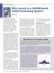
Digital video distribution is a major<br />
growth area – and not just on traditional<br />
surveillance platforms such as naval combat<br />
systems, maritime patrol aircraft, or<br />
armored scout vehicles. Digital distribution<br />
removes <strong>the</strong> straitjacket of wired<br />
analog distribution, <strong>with</strong> discrete cables<br />
per video source, enabling video to be<br />
distributed over multiple carriers over<br />
long distances and at high quality and high<br />
resolutions. In addition, many armored<br />
vehicles are now being equipped <strong>with</strong><br />
local situational awareness systems offering<br />
all-around vision <strong>with</strong> <strong>the</strong> hatches<br />
closed. These vehicles may also receive<br />
downlinked images of <strong>the</strong> battlefield from<br />
Unmanned Aerial Vehicle (UAV) sensors<br />
in real time.<br />
Digital video applications<br />
The most common applications are large,<br />
multisensor platforms <strong>with</strong> many crew<br />
stations, each one potentially able to view<br />
any-from-many video sources on one or<br />
several screens simultaneously. Distribution<br />
of analog video requires considerable<br />
cabling plus complex switching and<br />
scaling hardware at each crew station. The<br />
complexity of such systems is magnified<br />
by <strong>the</strong> recent introduction of higherresolution,<br />
point-to-point digital video/<br />
audio interfaces <strong>with</strong> <strong>the</strong>ir restricted<br />
transmission distances and cable routing<br />
issues. These include <strong>the</strong> PC standards<br />
such as High-Definition Multimedia<br />
Interface (HDMI) found in modern flatpanel<br />
TVs and monitors. Some military<br />
applications achieve uncompressed digital<br />
video transmission using <strong>the</strong> ARINC 818<br />
standard, which is based on Fibre<br />
Channel signaling (specifically FC-AV).<br />
Video compression and distribution as<br />
IP packets over an E<strong>the</strong>rnet network is<br />
a solution being adopted for large platforms.<br />
The same principles are being<br />
applied to many smaller platforms <strong>with</strong><br />
multisensor payloads that may be required<br />
to share data and images externally across<br />
<strong>the</strong> digital battlefield.<br />
However, compression can cause loss of<br />
clarity and detail and introduce delays<br />
into signal paths. Delay is usually unacceptable<br />
when used for fire direction or<br />
for driving a ground vehicle, making <strong>the</strong><br />
choice of compression algorithm critical.<br />
The most familiar standards for video<br />
compression, MPEG-2 and MPEG-4,<br />
add delays of typically 300 mS by using<br />
multiple frames to discriminate changes.<br />
There may also be a loss of picture<br />
integrity plus some additional recovery<br />
time if one frame is lost or corrupted<br />
during transmission. The alternative is<br />
to use frame-by-frame compression of<br />
JPEG2000, where coding and decoding<br />
operate at frame rate and any delays are<br />
limited to transmission times through a<br />
network. JPEG2000 also offers selectable<br />
compression ratios for optimum use<br />
of bandwidth. For example, <strong>with</strong> a typical<br />
compression ratio of 30:1, TV rate video<br />
only requires a bandwidth of 1 Mbps<br />
through a network.<br />
Managing costs and distribution<br />
JPEG2000 is appropriate for all types of<br />
video distribution, offering better quality<br />
and response at similar overall cost<br />
compared to MPEG. One example where<br />
<strong>the</strong> solution is often strongly dictated<br />
by budget is local situational awareness<br />
in an armored vehicle. This uses a number<br />
of cameras at TV resolution and will<br />
require little image processing. A typical<br />
configuration is for each camera to incorporate<br />
JPEG2000 compression, hooking<br />
up directly to <strong>the</strong> vehicle’s local network<br />
and using onboard embedded computing<br />
10 March/April 2009 <strong>Military</strong> EMBEDDED SYSTEMS
esources to decompress and display <strong>the</strong><br />
images on one or two local displays. By<br />
using embedded computing resources,<br />
images and annotations added by <strong>the</strong><br />
crew could also be distributed externally<br />
through radio or satellite links to command<br />
posts or to o<strong>the</strong>r vehicles on <strong>the</strong><br />
ground. Larger platforms such as naval<br />
combat systems or surveillance aircraft<br />
will host more complex applications<br />
requiring additional image or display<br />
processing; <strong>the</strong>se include target tracking,<br />
identification, and classification; sensor<br />
fusion; and windowing. The image processing<br />
will be more closely integrated<br />
<strong>with</strong> many embedded computing systems<br />
and will deal <strong>with</strong> video of much higher<br />
quality. This application will distribute<br />
not only compressed sensor video via <strong>the</strong><br />
network, but it will also have many cooperative<br />
participants sharing processed/<br />
syn<strong>the</strong>tic video from many sources (for<br />
example, from one combat system display<br />
console to many o<strong>the</strong>rs).<br />
Figure 1: JPEG2000 is now a well-accepted standard for high-quality video distribution, particularly in<br />
embedded systems modules such Curtiss-Wright’s Orion JPEG2000 PMC module.<br />
JPEG2000 is now a well-accepted standard<br />
for high-quality video distribution,<br />
particularly in embedded systems modules<br />
such <strong>the</strong> Orion JPEG2000 PMC<br />
module from Curtiss-Wright Controls<br />
Embedded Computing (CWCEC) shown<br />
in Figure 1. Technology improvements<br />
are set to greatly improve packaging and<br />
performance of this class of product;<br />
PCI Express is replacing older PCI and<br />
PCI-X parallel interfaces. Secondly, an<br />
FPGA can now be used for real-time<br />
JPEG2000 compression and decompression<br />
on multiple channels at HD resolutions<br />
and beyond, up to 1,920 x 1,200.<br />
These improvements make it possible to<br />
implement capability onto just a single<br />
XMC/PMC module, compatible <strong>with</strong> off<strong>the</strong>-shelf<br />
embedded computing standards,<br />
to support DVI as well as PAL/NTSC<br />
sensor and display video streams. In addition,<br />
such a module could operate as a<br />
JPEG2000 coprocessor for <strong>the</strong> interplatform,<br />
console-to-console, or platformto-platform<br />
class of video distribution.<br />
Moving compressed video as IP packets<br />
through a network saves space, weight, and<br />
cost by making more efficient use of what<br />
is often underutilized existing infrastructure.<br />
The new generation of JPEG2000<br />
products provides <strong>the</strong> capability to incorporate<br />
HD levels of video resolution <strong>with</strong><br />
<strong>the</strong> compression ratios and video quality<br />
to match current and future network,<br />
sensor, and display performance.<br />
To learn more, e-mail John at<br />
john.wemekamp@curtisswright.com.<br />
<strong>Military</strong> EMBEDDED SYSTEMS March/April 2009 11
Daily Briefing: News Snippets<br />
By Sharon Schnakenburg, Associate Editor<br />
www.mil-embedded.com/dailybriefing<br />
Photo courtesy of Boeing<br />
GPU computer sales plummet – Q4’08<br />
They’re high, <strong>the</strong>y’re low. They’re fast, <strong>the</strong>n <strong>the</strong>y’re slow. What<br />
are <strong>the</strong>y? 2008 shipments of GPU-equipped computers, according<br />
to a recent report by graphics research firm Jon Peddie<br />
Research (JPR). First <strong>the</strong> good news: Q3-2008’s tallies were<br />
atypically high, even for oft-successful third quarters. The bad<br />
news: Total GPU shipments for Q4-2008 hit a sluggish 72.35<br />
million, a significant decline from <strong>the</strong> 111.26 million shipped in<br />
Q3-2008 and 100.5 million in Q4-2007. Consequently, AMD,<br />
Intel, and NVIDIA market shares decreased between Q3-2008<br />
and Q4-2008 (Table 1). Meanwhile, desktop sales dropped<br />
39.5 percent and notebook shipments decreased 29 percent<br />
between <strong>the</strong> third and fourth quarters of 2008. Dr. Jon Peddie,<br />
JPR president, says, “We’re forecasting a strong Q3 and Q4 for<br />
2009 and bracing for what will probably be <strong>the</strong> worst Q1 and Q2<br />
decline we’ve seen since <strong>the</strong> Internet bubble pop of 2000.”<br />
Vendor Q3-2008 Market share Q4-2008 Market share<br />
AMD 22.90 20.6% 14.00 19.3%<br />
Intel 54.95 49.4% 34.59 47.8%<br />
NVIDIA 30.93 27.8% 22.20 30.7%<br />
Table 1: Source: JPR<br />
‘Avenger’ system defies old-time<br />
smoke screens<br />
While old TV and movies depict smoke screens as <strong>the</strong> best<br />
tactical maneuver in avoiding enemy detection, Boeing has successfully<br />
completed testing on a high-tech alternative: <strong>the</strong> Laser<br />
Avenger laser system. Laser Avenger fires a laser beam at enemy<br />
UAVs <strong>with</strong>out <strong>the</strong> gun flashes or missile exhaust produced by<br />
traditional weapons that can reveal troops’ locales. While a<br />
2007 demonstration of <strong>the</strong> laser system confirmed its ability to<br />
neutralize Unexploded Ordnance (UXO) and IEDs, recent tests<br />
conducted at White Sands Missile Range in New Mexico – and<br />
observed by U.S. Army Cruise Missile Defense Systems reps –<br />
showed Laser Avenger combat-vehicle capable of UAV disablement.<br />
To ready Laser Avenger for its recent exams, laser power<br />
was doubled, <strong>the</strong> design ruggedized and simplified, and sophisticated<br />
pointing and tracking capability added – all <strong>with</strong>in less<br />
than one year, Boeing reports.<br />
NASA’s Orion takes hands-off<br />
approach<br />
It would seem logical to have hardware physically present to<br />
develop it, modify it, or integrate it into a system – unless one<br />
uses a virtual platform. Case in point: Honeywell’s recent selection<br />
of Virtutech’s Simics virtual platform for NASA’s Orion<br />
spacecraft. Touted to reduce hardware iterations by one-half,<br />
Simics will provide a software development platform nearly a<br />
year before <strong>the</strong> crew exploration vehicle’s hardware is physically<br />
available. The Simics full systems simulator’s capabilities<br />
include resuming/saving execution, reverse and forward execution,<br />
fault injection, full deterministic behavior, and noninvasive<br />
debug and trace, among o<strong>the</strong>rs. Lockheed Martin is prime on<br />
Orion, which will transport crew members to <strong>the</strong> moon, <strong>the</strong><br />
International Space Station, and someday Mars.<br />
Laser pulses: Not <strong>the</strong> speed<br />
of light<br />
Though <strong>the</strong> speed of light was quantified long ago, <strong>the</strong> speed<br />
of laser pulses is still up for debate. However, a recent Phase II<br />
Small Business Technology Transfer (STTR) contract for<br />
$500,000 between <strong>the</strong> Naval Air Warfare Center (NAVAIR)<br />
and “ultrafast” laser producer Raydiance, Inc. aims to solve <strong>the</strong><br />
ambiguity. The contract fur<strong>the</strong>rs <strong>the</strong> work recently finished in<br />
Phase I, surrounding <strong>the</strong> ongoing development of new fiber technology<br />
that can be used to transmit “high-power Ultrashort Pulse<br />
(USP) or ‘ultrafast’ lasers over fiber.” The new technology’s<br />
target: NAVAIR apps including Electronic Countermeasures<br />
(ECM), LiDAR, and explosives detection, among o<strong>the</strong>rs.<br />
Phase II finds Raydiance renewing its Phase I collaboration <strong>with</strong><br />
MIT in enhancing <strong>the</strong> ultrafast laser’s weight, form factor, capabilities,<br />
and cost.<br />
For consideration in Daily Briefings, submit your press<br />
releases at http://submit.opensystemsmedia.com<br />
Submission does not guarantee inclusion.<br />
Artist rendering courtesy of NASA<br />
12 March/April 2009 <strong>Military</strong> EMBEDDED SYSTEMS
USAF thwarts critical interruptions<br />
Getting interrupted during a conversation can prove highly annoying<br />
to civilians. But an interruption in battlefield communications<br />
can prove much more frustrating – and even deadly. Accordingly,<br />
<strong>the</strong> U.S. Air Force commissioned Thales Communications<br />
to provide more than 700 of its 50-watt AN/VRC-111 Vehicle<br />
Adapter Amplifier (VAA) systems, along <strong>with</strong> more than 200<br />
20-watt AN/VRC-111 systems for <strong>the</strong> USAF’s Tactical Air<br />
Control Party Modernization Office (TACP-M). With several<br />
deliveries to Hanscom Air Force Base recently completed, each<br />
VAA includes dual AN/PRC-148 JTRS Enhanced Multiband<br />
Inter/Intra Team Radios (JEMs), rendering cable-free, fast radio<br />
dismount in under two seconds <strong>with</strong> no communications loss.<br />
The two-channel AN-VRC-111 VAA is an SDR-based system<br />
providing 50 W at frequencies of 30 to 88 MHz, or 20 W at frequencies<br />
of 90 to 512 MHz. The AN-VRC-111 system, on <strong>the</strong><br />
o<strong>the</strong>r hand, provides 20 W at frequencies of 30 to 512 MHz.<br />
Largest investment to produce<br />
smallest technology<br />
In what is purported as Intel’s “largest-ever investment for a<br />
new manufacturing process,” <strong>the</strong> company will invest $7 billion<br />
to build U.S. “advanced manufacturing facilities” to produce<br />
its smallest offering: 32 nm technology. The investment’s designated<br />
locations in Arizona, Oregon, and New Mexico are earmarked<br />
to support about 7,000 high-skill, high-paying positions.<br />
“We’re investing in America to keep Intel and our nation at <strong>the</strong><br />
forefront of innovation,” Intel CEO and President Paul Otellini<br />
said in a statement to <strong>the</strong> media. First up in Intel’s upcoming<br />
32 nm plan is <strong>the</strong> “Westmere” processor, which melds Nehalem<br />
technology <strong>with</strong> integrated graphics capabilities and is scheduled<br />
to begin production this year.<br />
Software companies experience<br />
economic gains<br />
In contrast to <strong>the</strong> downward spiral many industries and companies<br />
are experiencing, two software companies are reporting<br />
growth: Middleware specialist Real-Time Innovations (RTI)<br />
claims “record revenue for <strong>the</strong> seventh consecutive year” and a<br />
Compounded Annual Growth Rate (CAGR) of more than 44 percent<br />
for its core middleware offerings. International design wins,<br />
up by 80 percent from 2007, were among <strong>the</strong> primary growth factors.<br />
In addition, Tensoft, Inc. announced an increase in software<br />
revenue of 100 percent in 2008. Tensoft CEO Bob Scarborough<br />
credits a solid customer base and partnership <strong>with</strong> Microsoft as<br />
key to Tensoft’s 2008 success.<br />
LM stays ahead of <strong>the</strong> curve<br />
Lockheed Martin (LM) recently earned – five years earlier than<br />
required – <strong>the</strong> Italian Ministry of Defense’s (MoD’s) “industrial<br />
benefit requirement” signoff surrounding <strong>the</strong> acquisition of<br />
twenty-two C-130J airlifters. The industrial benefit requirement<br />
includes a broad spectrum of Italian companies and comprises<br />
initiatives such as license establishment, technology transfers,<br />
and LM’s direct investment in Italian industry. Italy’s Aeronautica<br />
Militare was one of <strong>the</strong> original C-130J customers in 1997,<br />
and its pilots have logged more than 75,000 flight hours <strong>the</strong>reon.<br />
The C-130J airlifter was developed to fulfill missions ranging<br />
from air-to-air refueling, to disaster relief, combat delivery, special<br />
operations, and more.<br />
Open source database reduces<br />
unknowns<br />
In association <strong>with</strong> a contract <strong>with</strong> <strong>the</strong> U.S. Department of Homeland<br />
Security, Coverity announced recent publication of its forpublic-use<br />
online “Scan” database of application architectures.<br />
Scan contains data “compiled” from more than 2,500 open source<br />
projects (www.scan.coverity.com), ga<strong>the</strong>red via <strong>the</strong> Coverity<br />
Architecture Analyzer. The website features software data from<br />
Postfix, Samba, Perl, Amanda, OpenPAM, TCL, NTP, Overdose,<br />
and Python, among many o<strong>the</strong>rs. Scan helps reduce design issues<br />
by enabling comparison of an architecture to various code bases,<br />
lending developers increased structural understanding. Scan also<br />
assists designers who are developing a module or plug-in by<br />
ensuring that <strong>the</strong> design meshes <strong>with</strong> expectations relevant to <strong>the</strong><br />
target open source project.<br />
U.S. Army ‘virtually’ scores<br />
accolades<br />
In 2002, <strong>the</strong> U.S. Army released its America’s Army PC game to<br />
give civilians virtual experience in soldiering on battlefields and<br />
in barracks. Its developers were even required to discharge weapons,<br />
conquer obstacle courses, participate in combat training, and<br />
observe paratrooper instruction to lend as much realism as possible.<br />
Those taking note include <strong>the</strong> game’s 9.7 million registered<br />
users (or “virtual army”) as well as <strong>the</strong> Guinness World Records<br />
organization. Accordingly, <strong>the</strong> 2009 Guinness Gamer’s Edition<br />
will grant America’s Army five awards: Largest Virtual Army;<br />
Most Downloaded War Video Game (42.6 million downloads);<br />
Most Hours Spent Playing a Free Online Shooter (230.9 million<br />
hours); Earliest <strong>Military</strong> Website to Support a Video Game<br />
(www.americasarmy.com); and Largest Traveling Game Simulator<br />
– Virtual Army Experience accommodates as many as<br />
50 players. America’s Army version 3.0 is set for release this year.<br />
Photo courtesy of U.S. Army. Soldiers in “America’s Army: True Soldiers” attack an enemy<br />
encampment in <strong>the</strong> fictional country of Ganzia. The player controls <strong>the</strong> weapon in <strong>the</strong> foreground.<br />
Before using a weapon in combat, players must meet Army training standards.<br />
<strong>Military</strong> EMBEDDED SYSTEMS March/April 2009 13
Legacy Software Migration<br />
By Bill Graham<br />
Migrating legacy applications to multicore:<br />
Not as scary as it sounds<br />
Multicore processors bring significant<br />
performance and power usage benefits<br />
to embedded systems, but <strong>the</strong>y also add<br />
<strong>the</strong> complexity of multiprocessing to <strong>the</strong><br />
legacy migration workload. None<strong>the</strong>less,<br />
development teams can successfully<br />
manage <strong>the</strong>ir transition to multicore<br />
by following some straightforward<br />
techniques.<br />
Port to a portable standard<br />
Often, migrating to multicore involves<br />
more than moving to a new processor. In<br />
many cases, developers must first port <strong>the</strong><br />
legacy code to a new programming language,<br />
compiler, or OS. Using an open<br />
standard such as POSIX is highly recommended,<br />
in light of its support of many<br />
general-purpose and real-time operating<br />
systems. Doing so will help ensure that<br />
large portions of <strong>the</strong> application, including<br />
its interface <strong>with</strong> <strong>the</strong> OS, are portable. Just<br />
as important, <strong>the</strong> POSIX standard has a<br />
proven history in multiprocessing systems,<br />
and a multicore processor is simply a<br />
multiprocessing System-on-Chip (SoC).<br />
Divide and conquer<br />
The OSs that support Symmetric Multiprocessing<br />
(SMP) are <strong>the</strong> best option for<br />
homogenous multicore processors. SMP<br />
leaves <strong>the</strong> complex details of allocating<br />
CPU resources to <strong>the</strong> OS, ra<strong>the</strong>r than to<br />
<strong>the</strong> application. From <strong>the</strong> application’s<br />
point of view, <strong>the</strong> interface to <strong>the</strong> OS<br />
remains <strong>the</strong> same, regardless of <strong>the</strong> number<br />
of cores, from 1 to N. Consequently,<br />
<strong>the</strong> application can scale easily as more<br />
cores are added.<br />
A multicore system running in SMP mode<br />
provides true parallelism, but some legacy<br />
applications were never designed for<br />
parallel execution. Often, large portions<br />
of <strong>the</strong> code do not use threads, which<br />
would allow different parts of <strong>the</strong> application<br />
to run in parallel or use threads<br />
only to isolate blocking system calls such<br />
as file or network I/O.<br />
Ano<strong>the</strong>r typical pitfall occurs when code<br />
uses a priority scheme to control access<br />
to shared memory. For instance, in a<br />
uniprocessor embedded system, <strong>the</strong> software<br />
developer can often assume that a<br />
high-priority thread and a low-priority<br />
thread will not access <strong>the</strong> memory simultaneously,<br />
since <strong>the</strong> high-priority thread<br />
will always preempt <strong>the</strong> low-priority<br />
thread. Thus, many programs fail to use<br />
a mutual exclusion lock (mutex) to properly<br />
synchronize access to <strong>the</strong> memory. In<br />
an SMP multicore system, however, both<br />
of <strong>the</strong>se threads can run in parallel and, as<br />
a result, access memory simultaneously<br />
<strong>with</strong> unpredictable results. O<strong>the</strong>r insidious<br />
problems might exist due to synchronization<br />
errors that work perfectly on a single<br />
processor system but surface only in<br />
multiprocessor execution.<br />
“... Insidious problems<br />
might exist due to<br />
synchronization errors<br />
that work perfectly on<br />
a single processor system<br />
but surface only in<br />
”<br />
multiprocessor execution.<br />
To solve such problems, developers can<br />
divide and conquer: isolate <strong>the</strong> problem<br />
code on a single core of <strong>the</strong> multicore<br />
chip until <strong>the</strong> code can be fixed. To do<br />
this, developers can use Bound Multiprocessing<br />
(BMP), an extension to SMP<br />
that allows selected processes to run on<br />
only a specified core or CPU. In effect,<br />
BMP provides a single-core, nonparallel<br />
execution environment for legacy code<br />
while allowing o<strong>the</strong>r code to leverage<br />
<strong>the</strong> full parallelism of SMP. The development<br />
team can subsequently remove <strong>the</strong><br />
CPU binding once <strong>the</strong>y have modified <strong>the</strong><br />
legacy code to behave properly in its new<br />
parallel environment.<br />
Leverage <strong>the</strong> tools<br />
Development teams must also use <strong>the</strong><br />
right tools. In particular, <strong>the</strong>y need visualization<br />
tools that help <strong>the</strong>m pinpoint areas<br />
where code is misbehaving in a parallel<br />
environment. Mostly, this effort involves<br />
<strong>the</strong> detection and correction of <strong>the</strong><br />
synchronization bugs mentioned earlier.<br />
Once an application is operating properly,<br />
it may still fail to take advantage of all<br />
of <strong>the</strong> multicore chip’s CPU capacity.<br />
Visualization tools can help here, too, by<br />
allowing developers to reduce contention<br />
for shared resources (hot spots), eliminate<br />
excessive thread migration or communication<br />
between cores, and find opportunities<br />
for parallelizing code. As <strong>the</strong><br />
number of cores increases in multicore<br />
platforms, visualization tools will be <strong>the</strong><br />
key to successfully leveraging <strong>the</strong> performance<br />
benefits that multicore offers.<br />
To provide such analysis, multicore<br />
visualization tools must reach beyond<br />
<strong>the</strong> scope of conventional debug tools.<br />
They must, for example, track threads<br />
as <strong>the</strong>y migrate from one core to ano<strong>the</strong>r<br />
and diagnose messages flowing between<br />
cores. They must also offer flexible control<br />
over which events are recorded and<br />
when, so that developers can focus on<br />
areas of concern.<br />
Making <strong>the</strong> transition<br />
“Multicore” does not need to be a bad<br />
word nor add ano<strong>the</strong>r roadblock to legacy<br />
migration. Adopting portable programming<br />
standards such as POSIX, using<br />
OSs designed for multicore platforms,<br />
isolating legacy code to run on a single<br />
core, and using visualization tools all<br />
make <strong>the</strong> transition less daunting.<br />
Bill Graham is product marketing<br />
manager at QNX Software Systems. He<br />
has more than 20 years of experience<br />
in <strong>the</strong> software industry, including<br />
embedded and real-time systems development,<br />
software development processes<br />
and techniques, UML modeling, and<br />
object-oriented design. He holds<br />
Bachelor’s and Master’s degrees in<br />
Electrical Engineering from Carleton<br />
University in Ottawa, Canada. He<br />
can be reached at bgraham@qnx.com.<br />
14 March/April 2009 <strong>Military</strong> EMBEDDED SYSTEMS
Legacy software: It’s <strong>the</strong> “new” thing<br />
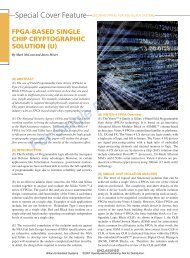
‘Legacy’ is not a four-letter word<br />
By Robert Dewar<br />
Though “legacy” code is often viewed negatively, it is proving itself a success in modern apps, thanks to its benefits of<br />
increased reliability and reduced effort. Two key aspects of this code reuse include developing reusable code and choosing<br />
appropriate legacy code.<br />
787 “Dreamliner” photo courtesy of Boeing<br />
I am often asked whe<strong>the</strong>r any new applications are being started<br />
from scratch in Ada. There are indeed some examples, a notable<br />
one being iFacts[1], a land-based component of <strong>the</strong> new air traffic<br />
control system for <strong>the</strong> United Kingdom’s National Air Traffic<br />
Services (NATS). This application is being developed in Ada,<br />
using <strong>the</strong> SPARK dialect <strong>with</strong> rigorous formal methods. However,<br />
that project is an exception. Most new large applications<br />
are not started from scratch in Ada, or in any o<strong>the</strong>r language for<br />
that matter. Instead, <strong>the</strong>y make varying use of so-called “legacy”<br />
components, reusing code from earlier systems.<br />
The word “legacy” is perhaps ill-chosen. For many, it seems to<br />
denote rusty old junkware, and many programmers would clearly<br />
prefer to invent (and often reinvent) by writing new code. But<br />
“legacy software” can also mean effectively deploying reusable<br />
modules and systems, an obviously desirable goal.<br />
There are many reasons why reuse beats writing new code.<br />
First, and most obviously, developing complex software is an<br />
increasingly expensive proposition, and anything that can reduce<br />
this effort and its associated costs is highly desirable. But perhaps<br />
even more importantly, tried-and-true code that has been<br />
effectively deployed is likely to be reliable.<br />
Paths to reliable code<br />
There are two ra<strong>the</strong>r different ways to demonstrate reliability<br />
for new applications. The first is to use powerful techniques that<br />
prevent defects from being introduced. The iFacts system exemplifies<br />
this approach. It is written almost entirely in SPARK<br />
(Figure 1) using ma<strong>the</strong>matical proof techniques to ensure freedom<br />
from such defects as unanticipated arithmetic overflow or<br />
out-of-range array indices.<br />
The use of formal methods will become more prominent as more<br />
applications have strenuous safety and security requirements. For<br />
example, <strong>the</strong> increased rigor associated <strong>with</strong> formal approaches<br />
helps developers address <strong>the</strong> higher levels of safety standards such<br />
as DO-178B[2] for commercial avionics. And <strong>the</strong> highest level of<br />
security in <strong>the</strong> Common Criteria[3], EAL7, actually requires fully<br />
formal techniques (Figure 2). The recently released Tokeneer system[4],<br />
a demonstration project sponsored by NSA and engineered<br />
using SPARK, illustrates this formal approach to ensuring freedom<br />
from defects. Tokeneer is a program that controls access to a secure<br />
enclave using biometric data. The project’s goal is to show that it<br />
is feasible (and practical) to create such an application by formally<br />
proving <strong>the</strong> necessary security properties.<br />
Figure 1: The iFacts system, a land-based component of <strong>the</strong> new<br />
air traffic control system for <strong>the</strong> United Kingdom’s National Air Traffic<br />
Services (NATS), is being developed in Ada, using <strong>the</strong> SPARK dialect<br />
<strong>with</strong> rigorous formal methods.<br />
However, <strong>the</strong>re is ano<strong>the</strong>r path to reliability: long-term deployment<br />
of code in real-world systems. Over years of use, such<br />
strenuous testing can bring large systems to effectively converge<br />
to a state of impressive reliability. Examples are <strong>the</strong> Apache<br />
server[5], <strong>the</strong> PARS airline reservation system[6], and versions<br />
Figure 2: The increased rigor associated <strong>with</strong> formal approaches helps<br />
developers address <strong>the</strong> higher levels of safety standards such as DO-178B<br />
for commercial avionics.<br />
16 March/April 2009 <strong>Military</strong> EMBEDDED SYSTEMS
of <strong>the</strong> AIX operating system[7]. The latter is an interesting data<br />
point, since <strong>the</strong> iFacts application is built on top of AIX, and<br />
<strong>the</strong>re would not be much point in creating a highly reliable application<br />
if <strong>the</strong> underlying operating system itself was not trusted.<br />
This trust comes not from a formal demonstration of correctness<br />
(which is beyond <strong>the</strong> state of <strong>the</strong> art), but from NATS experience<br />
in deploying AIX in live air traffic control systems for more than<br />
a decade. Of course, past performance is not a guarantee against<br />
bugs appearing in <strong>the</strong> future, but in <strong>the</strong> practical world of system<br />
development, <strong>with</strong> finite time and resources, <strong>the</strong>re is good<br />
rationale for <strong>the</strong> position, “If it ain’t broke, don’t rewrite it.”<br />
It seems obvious, <strong>the</strong>n, that reusing legacy code is a good thing.<br />
However, many program managers almost seem to apologize<br />
for going this route. Interestingly, <strong>the</strong>y might have some quite<br />
understandable rationale. Let’s look at two aspects of reuse that<br />
can cause problems if not handled carefully: developing reusable<br />
code and choosing appropriate legacy code.<br />
Developing reusable code<br />
How does one create reusable code in <strong>the</strong> first place? If a component<br />
is to be effectively reused, it must be written in a highly<br />
portable manner, since it will likely be redeployed in a different<br />
environment – one that uses a different architecture or compiler<br />
from <strong>the</strong> original. A software component’s portability depends on<br />
<strong>the</strong> chosen programming language and how <strong>the</strong> language’s features<br />
are used. Undefined or implementation-dependent behaviors<br />
are particularly problematic, and <strong>the</strong>se vary across languages. For<br />
example, <strong>the</strong> effect of integer overflow is undefined in C, but many<br />
compilers have implemented “wraparound” treatment and many<br />
C programmers have come to rely on this as <strong>the</strong> expected behavior.<br />
The integer overflow’s effect is well-defined in Java (wraparound<br />
semantics, which might, however, cause o<strong>the</strong>r problems) and in<br />
Ada (raising an exception). O<strong>the</strong>r potential sources of nonportability<br />
are data alignment and pointer size assumptions, compilerdependent<br />
extensions, and target-system-specific libraries.<br />
For effective reuse, program components must be well designed<br />
and documented. From an interface specification, programmers<br />
must be able to tell exactly what <strong>the</strong> code is supposed to do and<br />
how it should be (re)used. Equally important, internal comments<br />
must provide sufficient detail and be consistent <strong>with</strong> <strong>the</strong> code<br />
so that a programmer needing to modify <strong>the</strong> component years<br />
later can understand how it works. Designing for effective reuse<br />
definitely takes skill and can increase <strong>the</strong> expense and time<br />
required for <strong>the</strong> original implementation. Consequently, <strong>the</strong> extra<br />
benefits are potential and long term, but <strong>the</strong> additional costs are<br />
actual and short term. It is easy to understand why, faced <strong>with</strong><br />
that tradeoff, software project managers are not rushing to make<br />
design for reuse one of <strong>the</strong>ir major priorities.<br />
Choosing appropriate legacy code<br />
The second vital factor in successfully reusing code is ensuring<br />
fitness-for-purpose. To benefit from well-used code’s reliability,<br />
code must be used correctly in its new context. Neglecting to<br />
follow this essential principle led to <strong>the</strong> spectacular destruction<br />
of <strong>the</strong> Ariane 5 rocket[8] during its initial launch. Some reused<br />
code from Ariane 4 caused a catastrophic system failure because<br />
<strong>the</strong> specifications for an important flight parameter of <strong>the</strong> new<br />
rocket did not match those of <strong>the</strong> earlier rocket. An unexpected<br />
out-of-range condition occurred during a conversion from floating<br />
point to integer, which led to a guidance system shutdown.<br />
Fortunately, <strong>the</strong>re are certainly also many instances of successful<br />
legacy software use. Payroll systems, typically written in COBOL,<br />
<strong>Military</strong> EMBEDDED SYSTEMS March/April 2009 17
Legacy software: It’s <strong>the</strong> “new” thing<br />
serve as an illustration. Tax laws change annually, often radically,<br />
but <strong>the</strong> design of parameterizable modular components obviates<br />
<strong>the</strong> need to rewrite <strong>the</strong>se systems each year. Appropriate<br />
languages, programming styles, libraries, and management practices<br />
are crucial factors in such successful legacy code use.<br />
In <strong>with</strong> <strong>the</strong> old, out <strong>with</strong> <strong>the</strong> new<br />
Despite failures in some cases such as Ariane 5, proper legacy<br />
code reuse can reduce costs and increase reliability and safety.<br />
A recent highly visible example is <strong>the</strong> avionics system of <strong>the</strong><br />
Boeing 787 “Dreamliner.” (See photo, first page of this article.)<br />
Dreamliner is an all-new plane <strong>with</strong> all-new hardware technology<br />
and materials, but <strong>the</strong> software aboard has a significant proportion<br />
of reused modules from o<strong>the</strong>r Boeing airplanes. So when someone<br />
asks you, “What’s new in your latest software system?” let’s hope<br />
you can answer, “Same old, same old.” Whe<strong>the</strong>r it’s called “legacy<br />
code” or “reusable components,” <strong>the</strong> benefits can be huge.<br />
References<br />
1. “NATS Pioneers Biggest ATC Advance Since Radar,” www.nats.co.uk/<br />
article/218/62/nats_pioneers_biggest_atc_advance_since_radar.html<br />
2. RTCA SC-167/EUROCAE WG-12. RTCA/DO-178B. Software<br />
Considerations in Airborne Systems and Equipment Certification.<br />
Dec. 1992.<br />
3. The Common Criteria Portal. Common Criteria for Information<br />
Technology Security Evaluation. Vers. 3.1. Sept. 2006,<br />
www.commoncriteriaportal.org/<strong>the</strong>cc.html<br />
4. The Tokeneer Project, www.adacore.com/home/gnatpro/tokeneer<br />
5. The Apache Software Foundation, www.apache.org<br />
6. Origins and Development of Transaction Processing Facility,<br />
www.blackbeard.com/tpf/tpfhist.htm<br />
7. IBM AIX, www-03.ibm.com/systems/power/software/aix/index.html<br />
8. J.L. Lyons, Report of <strong>the</strong> Inquiry Board into <strong>the</strong> Failure of Flight 501 of<br />
<strong>the</strong> Ariane 5 Rocket. European Space Agency Report, Paris, July 1996<br />
(annotated), www.jacobs.com.au/_lib/pdf/Ariane%20501%20Failure.pdf<br />
Dr. Robert Dewar is cofounder,<br />
president, and CEO of AdaCore; he<br />
has also had a distinguished career as<br />
a professor of Computer Science at <strong>the</strong><br />
Courant Institute of New York University.<br />
He has been involved <strong>with</strong> <strong>the</strong> Ada<br />
programming language since its inception<br />
in <strong>the</strong> early 1980s and, as codirector of<br />
both <strong>the</strong> Ada-Ed and GNAT projects, led <strong>the</strong> NYU team that<br />
developed <strong>the</strong> first validated Ada compiler. He has coauthored<br />
compilers for SPITBOL (SNOBOL), Realia COBOL for <strong>the</strong> PC<br />
(now marketed by Computer Associates), and Alsys Ada. He is<br />
also a principal architect of AdaCore’s GNAT Ada technology.<br />
He has also written several real-time operating systems for<br />
Honeywell Inc. He can be reached at dewar@adacore.com.<br />
The full-length version of this article appears at<br />
www.mil-embedded.com/articles/id/?3729.<br />
AdaCore<br />
212-620-7300<br />
www.adacore.com<br />
18 March/April 2009 <strong>Military</strong> EMBEDDED SYSTEMS
Hardware: Real-world hardware<br />
Case study: Direct spray maximizes<br />
environmental isolation and flexibility<br />
on airborne platforms<br />
By Andy Finch and Jeff Weiler<br />
<strong>Military</strong> embedded systems experience harsh and rugged environments.<br />
In recent years, <strong>the</strong> power levels of <strong>the</strong> electronics deployed in <strong>the</strong>se systems<br />
have been rising rapidly. The combination of <strong>the</strong> harsh environments <strong>with</strong> <strong>the</strong><br />
rising heat loads of <strong>the</strong> electronics has forced vendors to develop more effective<br />
packaging technology. Meanwhile, direct spray cooling is proving itself an<br />
acceptable alternative to air and conduction cooling, providing exceptional<br />
environmental isolation and enabling lower lifetime cost of ownership. A case<br />
study is presented on Northrop Grumman’s (NG’s) Airborne Signals Intelligence<br />
Payload (ASIP), which includes a configuration of <strong>the</strong> direct spray cooled Multi-<br />
Platform Enclosure (MPE) and appears on NG’s manned U-2 high-altitude<br />
reconnaissance plane and <strong>the</strong> Global Hawk UAV.<br />
Existing and emerging applications running<br />
on military embedded systems are<br />
demanding ever-increasing computational<br />
power and communications bandwidths.<br />
For example, UAVs running signal intelligence<br />
systems or executing real-time<br />
image processing are driving impressive<br />
power densities at <strong>the</strong> board, chassis, and<br />
platform levels. Even more impressive<br />
are <strong>the</strong> demands created by radar processing<br />
systems, <strong>with</strong> system-level power<br />
consumption in <strong>the</strong> tens of kilowatts. At<br />
<strong>the</strong> same time, platform integrators are<br />
requiring smaller, lighter, and more efficient<br />
board and chassis-level products.<br />
Thus, platform integrators are forced to<br />
look for alternative cooling solutions.<br />
A number of liquid-based cooling approaches<br />
exist. Most familiar to end users<br />
Platform Requirements<br />
are conduction-cooled systems. In addition,<br />
<strong>the</strong> Liquid Flow Through (LFT)<br />
cooling approach is emerging, which typically<br />
uses PolyAlphaOlefin (PAO) as <strong>the</strong><br />
coolant but differs from conduction cooling<br />
by delivering coolant to liquid-cooled<br />
cold plates mounted to components on<br />
<strong>the</strong> electronics[1]. Increasingly, direct<br />
spray is being viewed as an acceptable<br />
alternative to air and conduction cooling,<br />
providing excellent environmental isolation<br />
(Table 1) and enabling lower lifetime<br />
Temperature (°C) -65 to +71<br />
Altitude (ft) 25,000-70,000<br />
Temperature Gradients Air Conduction Direct Spray<br />
Enclosure<br />
20 March/April 2009 <strong>Military</strong> EMBEDDED SYSTEMS<br />
ΔT°C (T slot n - T slot 1 ) 20 10 2<br />
Available Cooling Capacity (W/slot) 100 100¹ 500<br />
Projected Enclosure Capability<br />
Cooling Capacity (W/slot) 200² 200³ 850-1,000<br />
¹Industry data for conduction. Few applications achieve this power density.<br />
²Industry data for Air Flow Thru (AFT) boards and enclosure<br />
³Industry data for Liquid Cold Plate <strong>with</strong> conduction enclosure and boards<br />
TABLE 1: Temperature requirements and cooling capacity comparison – Increasingly, direct spray<br />
is being viewed as an acceptable alternative to air and conduction cooling, providing excellent<br />
environmental isolation.
Multi-Platform Enclosure (MPE) for<br />
today’s military embedded systems<br />
It is critical to protect <strong>the</strong> payload electronics<br />
on military platforms from <strong>the</strong> effects of<br />
vibration, shock, sand, salt spray, and EMI,<br />
while simultaneously providing effective<br />
<strong>the</strong>rmal management. The Multi-Platform<br />
Enclosure (MPE) shown in Figure 1 utilizes<br />
direct spray technology and is designed to<br />
provide environmental isolation from <strong>the</strong><br />
harsh environments experienced during<br />
military use. Rugged or commercial-grade<br />
electronics can be housed inside <strong>the</strong> sealed<br />
enclosure, isolating electronics from sand,<br />
blowing dust, humidity, and many o<strong>the</strong>r<br />
undesirable operating conditions.<br />
Figure 1: The Multi-Platform Enclosure (MPE)<br />
utilizes direct spray technology and is designed<br />
to provide environmental isolation from <strong>the</strong><br />
harsh environments experienced during<br />
military use.<br />
The MPE’s predecessor was first developed for <strong>the</strong> Navy’s EA-6B Prowler platform, specifically<br />
for <strong>the</strong> Prowler’s aft power supply, to provide <strong>the</strong> necessary environmental isolation<br />
and <strong>the</strong>rmal management. At <strong>the</strong> time of engagement <strong>with</strong> <strong>the</strong> Navy, <strong>the</strong> EA-6B’s air-cooled<br />
aft power supply had a failure rate in <strong>the</strong> low 100s of hours. In preparation for flight testing,<br />
<strong>the</strong> power supply and its chassis were subjected to a full suite of MIL-STD testing, including<br />
catapult launches, arresting hook, shock, vibration, turbulence, and constant acceleration<br />
testing. In addition, <strong>the</strong> direct spray enclosure accumulated more than 400 hours of<br />
Prowler testing. By <strong>the</strong> conclusion of <strong>the</strong> testing, it was estimated that <strong>the</strong> MTBF of <strong>the</strong><br />
aft power supply had risen by more than 1,900 percent (to 3,000 hours). In recent years,<br />
DoD adoption of <strong>the</strong> MPE has been accelerating, and <strong>the</strong> Global Hawk ASIP is a relevant<br />
example.<br />
cost of ownership. These principles are<br />
illustrated in <strong>the</strong> following case study on<br />
<strong>the</strong> Airborne Signals Intelligence Payload<br />
(ASIP), to be installed on all Block 30<br />
Global Hawk aircraft.<br />
USAF Airborne Signals<br />
Intelligence Payload (ASIP)<br />
ASIP, developed by Northrop Grumman<br />
(NG) for <strong>the</strong> U.S. Air Force, is <strong>the</strong> nextgeneration<br />
signals intelligence sensor.<br />
The system detects, identifies, and locates<br />
radar and o<strong>the</strong>r types of electronic and<br />
modern communication signals[2]. The<br />
sensor first flew on Global Hawk in 2005<br />
and recently completed extensive qualification<br />
flights on <strong>the</strong> U-2 high-altitude<br />
reconnaissance plane.<br />
Environmental isolation<br />
Figure 2 shows <strong>the</strong> ASIP’s enclosure, a<br />
configuration of <strong>the</strong> direct spray cooled<br />
MPE (see sidebar) designed to environmentally<br />
isolate <strong>the</strong> sensitive electronics<br />
and provide necessary <strong>the</strong>rmal management.<br />
Flying on <strong>the</strong> U-2 or UAV, <strong>the</strong> payload<br />
housed in <strong>the</strong> unpressurized areas in<br />
<strong>the</strong> aircraft is subjected to extreme environmental<br />
conditions: temperatures as<br />
high as +70 °C at sea level and -65 °C at<br />
70,000 feet.<br />
The electronics packaging enabled by<br />
<strong>the</strong> direct spray system allows NG to<br />
Figure 2: The ASIP’s enclosure, a configuration<br />
of <strong>the</strong> direct spray cooled MPE, is designed to<br />
environmentally isolate sensitive electronics<br />
and provide necessary <strong>the</strong>rmal management.<br />
field commercial grade electronics. Even<br />
in harsh environments, <strong>the</strong> commercial<br />
grade electronics successfully survive<br />
<strong>the</strong> rigors of <strong>the</strong> airborne platform. Typical<br />
ratings for fully rugged boards are<br />
in excess of 10 Grms and can be as high<br />
as 20 Grms. The vibration profile for<br />
Global Hawk is 2.5 Grms. Many of <strong>the</strong><br />
electronics were only rated for 2.7 and<br />
5.1 Grms sine profile from 15-2,000 Hz<br />
for operational and endurance profiles,<br />
respectively. Depending on <strong>the</strong> vehicle<br />
profile, stiffening ribs may be added<br />
to commercial cards. With <strong>the</strong> cost of<br />
fully rugged boards often double that of<br />
commercial grade electronics, significant<br />
life-cycle cost savings can be gleaned<br />
<strong>with</strong> less rugged cards.<br />
<strong>Military</strong> EMBEDDED SYSTEMS March/April 2009 21
Hardware: Real-world hardware<br />
Ano<strong>the</strong>r intrinsic flexibility of direct<br />
spray enclosures is acceptance of varying<br />
heat densities. In ASIP, different card sets<br />
are used for applications ranging from<br />
600 to 1,700 W in enclosure power, yet<br />
<strong>the</strong> enclosure is identical between all use<br />
cases. For diverse heat loads, an external<br />
heat exchanger easily scales <strong>with</strong> power<br />
densities. Heat rejection options include<br />
fuel, PAO, EGW, RAM air, ambient air,<br />
or skin/hull. Dependence on platform<br />
infrastructure for cooling options is eliminated<br />
as <strong>the</strong> direct spray enclosure and<br />
heat exchanger act as a self-contained<br />
system in pressurized or unpressurized<br />
environments.<br />
Several ASIP cards are RF receiver cards<br />
tuned to between 20 and 3,000 MHz,<br />
while o<strong>the</strong>r cards range up to 18 GHz.<br />
With air-cooled systems, <strong>the</strong> electronics<br />
closest to <strong>the</strong> air supply are coolest while<br />
those near <strong>the</strong> air exhaust operate hotter.<br />
Conduction cards also create a <strong>the</strong>rmal<br />
“<br />
NG took advantage<br />
of <strong>the</strong> innate ability of<br />
direct spray to limit<br />
<strong>the</strong> temperature gradient<br />
to less than 2 °C across<br />
a 20-slot system <strong>with</strong><br />
power densities<br />
ranging from 30 to<br />
60 W per board.<br />
”<br />
gradient from <strong>the</strong> middle of <strong>the</strong> enclosure<br />
to <strong>the</strong> first and last slots. Due to temperature<br />
sensitivity of <strong>the</strong> RF electronics,<br />
compensation is usually required between<br />
cards in <strong>the</strong> enclosure. NG took advantage<br />
of <strong>the</strong> innate ability of direct spray to limit<br />
<strong>the</strong> temperature gradient to less than 2 °C<br />
across a 20-slot system <strong>with</strong> power densities<br />
ranging from 30 to 60 W per board.<br />
In <strong>the</strong> ASIP enclosure, <strong>the</strong> electronics are<br />
maintained between +30 °C and +50 °C<br />
while <strong>the</strong> ambient temperature ranges<br />
from -65 °C to +71 °C.<br />
Also, heat fluxes up to 50 W/cm 2 are found<br />
on bare die processors such as <strong>the</strong> 1.8 GHz<br />
Pentium M and are similar to those used in<br />
ASIP. With 70 °C inlet fluid, direct spray<br />
is able to maintain die temperatures at or<br />
below 90 °C. This is at least 10 °C lower<br />
than conduction-cooled enclosures. For<br />
electronics, it is widely accepted that for<br />
every 10 °C in temperature rise, reliability<br />
is reduced by 50 percent. The reliability<br />
impact of pumps, valves, and controllers<br />
is easily overcome by doubling <strong>the</strong> reliability<br />
of twenty 6U cards.<br />
Efficient technology refresh means<br />
lower ownership costs<br />
Integrators face <strong>the</strong> challenge of integrating<br />
air- and conduction-cooled boards on<br />
<strong>the</strong> same aircraft. Traditionally, it is not<br />
possible to mix electronics in <strong>the</strong> same<br />
enclosure due to constraints in both board<br />
and enclosure designs. For <strong>the</strong> ASIP sensor,<br />
NG was able to do just that by com-<br />
22 March/April 2009 <strong>Military</strong> EMBEDDED SYSTEMS
ining proprietary boards, commercial<br />
grade air-cooled SBCs, and o<strong>the</strong>r commercial<br />
Radio Frequency (RF) receiver<br />
cards into <strong>the</strong> enclosure. The enclosure<br />
consists of 20 user slots <strong>with</strong> inherent<br />
flexibility to mix and match electronics<br />
in unconditioned space and pressurized<br />
locations on <strong>the</strong> platform.<br />
This electronics packaging technology<br />
enables smaller, lighter, power-efficient<br />
systems that can go through a technology<br />
refresh in a matter of months as opposed<br />
to years, providing for significantly lower<br />
total cost of ownership over <strong>the</strong> lifetime<br />
of <strong>the</strong> program.<br />
Jeff Weiler is a technical director for SprayCool. Since<br />
joining <strong>the</strong> company in 1992, he has held a variety of<br />
engineering and management positions, <strong>with</strong> responsibilities<br />
including technical oversight into product development, concept<br />
development, sales and business development, and customer<br />
interface. Jeff earned a BSME from Washington State University.<br />
He can be contacted at jweiler@spraycool.com.<br />
SprayCool<br />
866-993-2665<br />
www.spraycool.com<br />
Direct spray enclosures meet<br />
today’s demands<br />
The direct spray enclosures have been<br />
thoroughly evaluated for performance,<br />
reliability, and maintainability in harsh<br />
environments. The ability to protect<br />
sensitive electronics under extreme altitude,<br />
temperature, and vibration has been<br />
proven on platforms like U-2 and Global<br />
Hawk. The inherent flexibility in <strong>the</strong><br />
selection of electronics enhances <strong>the</strong> utility<br />
of direct spray enclosures on legacy<br />
platforms and developmental aircraft,<br />
resulting in lower ownership costs.<br />
References:<br />
1. Harvey, R., and Odar, A., 2007, “Liquid<br />
Cooling Facilitates Tomorrow’s Embedded<br />
Systems,” <strong>Military</strong> Embedded Systems,<br />
Vol. 3, No. 6, Nov/Dec 2007.<br />
2. Avionics Magazine, 2007, “Northrop<br />
Grumman Completes ASIP Testing,” May 17,<br />
2007 edition (see also www.aviationtoday.com/<br />
av/topstories/11724.html).<br />
Andy Finch is a<br />
product manager<br />
for SprayCool. Since<br />
joining SprayCool<br />
in 2000, he has<br />
held engineering<br />
and management<br />
positions supporting<br />
program management, product<br />
development, and systems engineering.<br />
Prior to SprayCool, he developed<br />
control systems and automated<br />
equipment for <strong>the</strong> food processing,<br />
agricultural, and HVAC industries.<br />
Andy earned a BSME from <strong>the</strong> University<br />
of Idaho, an MS in Engineering<br />
from Purdue University, and an MBA<br />
from Indiana University. He can be<br />
contacted at afinch@spraycool.com.<br />
<strong>Military</strong> EMBEDDED SYSTEMS March/April 2009 23
Hardware: Real-world hardware<br />
ARINC 818 tackles<br />
tough sensor fusion issues<br />
By Jon Alexander and Tim Keller<br />
Sensor fusion systems continue to proliferate in military applications like surveillance, target tracking, and missile defense,<br />
but <strong>the</strong>y bring <strong>the</strong>ir share of system-level challenges such as sensor synchronization, cabling weight, distance restrictions, and<br />
EMI. The authors discuss how ARINC 818 (Avionics Digital Video Bus) can be used as a flexible sensor interface to solve <strong>the</strong>se<br />
system-level issues. Additionally, a bidirectional ARINC 818 system architecture scheme for time multiplexing multiple sensors<br />
onto a single fiber and implementing a return-path for sensor command and control is described.<br />
U.S. Air Force photo by Staff Sgt. Aaron Allmon II<br />
As sensor fusion systems proliferate in<br />
applications like enhanced vision, surveillance,<br />
target tracking, and missile defense,<br />
many system-level challenges exist when<br />
processing is executed remotely from <strong>the</strong><br />
sensor pod including: sensor synchronization,<br />
cabling weight, distance restrictions,<br />
and EMI. The ARINC 818 protocol, which<br />
has been used extensively in aerospace<br />
video systems such as cockpit displays,<br />
can be used as a flexible sensor interface<br />
to solve <strong>the</strong>se system-level issues. A bidirectional<br />
ARINC 818 system architecture<br />
is described including a scheme for<br />
time multiplexing multiple sensors onto<br />
a single fiber and implementing a return<br />
path for sensor command and control.<br />
Overview of ARINC 818 protocol<br />
ARINC 818 is relatively new, and many<br />
engineers are not yet familiar <strong>with</strong> <strong>the</strong> protocol.<br />
Before describing how to use ARINC<br />
818 in sensor fusion systems, an overview<br />
of <strong>the</strong> protocol will aid <strong>the</strong> discussion.<br />
The standard, titled Avionics Digital<br />
Video Bus (ADVB), is based on <strong>the</strong> Fibre<br />
Channel Audio Video (FC-AV) standard<br />
and is an adaptation of Fibre Channel<br />
that adds video transport capabilities.<br />
But where <strong>the</strong> FC-AV standard intends to<br />
support a very broad set of industries and<br />
applications, ADVB focuses on <strong>the</strong> critical<br />
needs of avionics video. ADVB is simplified<br />
from FC-AV <strong>with</strong> no requirements for<br />
link initialization, flow control, or o<strong>the</strong>r<br />
Fibre Channel exchanges such as port<br />
login. ADVB is defined as a unidirectional<br />
link, and although simplified, ADVB<br />
retains attributes of Fibre Channel that<br />
are beneficial for mission-critical video<br />
applications, such as high speed, high<br />
reliability, low latency, and flexibility.<br />
Additionally, ARINC 818 is a pointto-point,<br />
8B/10B encoded protocol for<br />
serial transmission of video and data. The<br />
protocol is packetized, video-centric, and<br />
very flexible, supporting an array of complex<br />
video implementations including<br />
<strong>the</strong> multiplexing of several video streams<br />
onto a single link. ARINC 818 and FC-AV<br />
define link speeds from 1 Gbps to 8 Gbps<br />
<strong>with</strong> a bandwidth up to 800 MBps, which<br />
accommodates <strong>the</strong> most demanding<br />
sensor-fusion applications.<br />
ADVB packet structure<br />
The ADVB frame shown in Figure 1 is<br />
ARINC 818’s basic transport mechanism.<br />
It is important to refer to <strong>the</strong>se packets as<br />
“ADVB frames” ra<strong>the</strong>r than simply as<br />
“frames,” to eliminate potential confusion<br />
<strong>with</strong> video frames.<br />
FC Frame<br />
SOF FC Header Payload CRC EOF<br />
Figure 1: The ADVB frame is <strong>the</strong> basic<br />
transport mechanism for ARINC 818.<br />
The start of an ADVB frame is signaled<br />
by a Start-Of-Frame (SOF) 4-byte ordered<br />
set and terminated <strong>with</strong> an End-Of-Frame<br />
(EOF) ordered set. Every ADVB frame<br />
has a standard Fibre Channel header<br />
comprised of six 32-bit words. These<br />
header words pertain to such things as<br />
ADVB frame origin and intended destination<br />
and ADVB frame position <strong>with</strong>in<br />
<strong>the</strong> sequence. The Source ID (SID) field<br />
in <strong>the</strong> ADVB frame header allows video<br />
from each sensor to be distinguished from<br />
<strong>the</strong> o<strong>the</strong>r sensors.<br />
26 March/April 2009 <strong>Military</strong> EMBEDDED SYSTEMS
The “payload” contains ei<strong>the</strong>r video,<br />
video parameters, or ancillary data. The<br />
payload can vary in size but is limited to<br />
2,112 bytes per ADVB frame. To ensure<br />
data integrity, all ADVB frames have a<br />
32-bit Cyclic Redundancy Check (CRC)<br />
calculated for data between <strong>the</strong> SOF and<br />
<strong>the</strong> CRC word. The CRC is <strong>the</strong> same<br />
32-bit polynomial calculation defined for<br />
Fibre Channel.<br />
ADVB container structure<br />
The ARINC 818 specification defines<br />
a “container” as a set of ADVB frames<br />
used to transport video. In o<strong>the</strong>r words,<br />
a video image and data are encapsulated<br />
into a “container” that spans many ADVB<br />
frames. The “payload” of each ADVB<br />
frame contains ei<strong>the</strong>r data or video.<br />
Within a container, ARINC 818 defines<br />
“objects” that contain certain types of<br />
data. That is, certain ADVB frames<br />
<strong>with</strong>in <strong>the</strong> container are part of an object.<br />
The four types of objects found <strong>with</strong>in a<br />
container are shown in Table 1.<br />
ceiver. In <strong>the</strong> example, <strong>the</strong> command and<br />
control path is shown as ARINC 818, but<br />
it could be achieved <strong>with</strong> an RS-422 or<br />
similar data bus if a high-speed bus like<br />
ARINC 818 isn’t required. In this example,<br />
ARINC 818 (3.187 Gbps) is more than<br />
300 times faster than RS-422 (10 Mbps).<br />
LWIR<br />
Sensor 1<br />
SID 1<br />
SWIR<br />
Sensor 2<br />
SID 2<br />
Optical<br />
Sensor 3<br />
SID 3<br />
FIFO<br />
FIFO<br />
FIFO<br />
Priority<br />
Scheduler<br />
The sensors may also have ARINC 818<br />
interfaces. An ARINC 818 interface can<br />
be designed into <strong>the</strong> sensors using ei<strong>the</strong>r<br />
a COTS converter board (for example,<br />
RS-170 to ARINC 818) or an ARINC 818<br />
IP core implemented in an FPGA.<br />
Sensor<br />
Mux<br />
Command & Control<br />
Remote ARINC 818 Sensor Interface Box<br />
ADVB<br />
Frame<br />
Maker<br />
ARINC 818 Video<br />
ARINC 818<br />
Command<br />
Mission<br />
Processor<br />
Mission Processor ARINC 818<br />
Sensor Interface<br />
Figure 2: A sensor interface module, colocated <strong>with</strong> <strong>the</strong> sensors, is used to time multiplex video from<br />
three sensors onto a single ADVB link.<br />
Object<br />
Data<br />
0 Ancillary data<br />
1 Audio (not used)<br />
2 Video: progressive or odd field<br />
3 Video: even field<br />
TABLE 1: ADVB frames <strong>with</strong>in <strong>the</strong> container are<br />
part of an object, and four types of objects are<br />
found <strong>with</strong>in a container.<br />
In most cases, a single container maps<br />
exactly to a single video frame. An example<br />
will clarify how video is transported:<br />
To transport an XGA video frame (1,024<br />
x 768, 24-bit color), ARINC 818 will<br />
use a total of 1,537 ADVB frames. The<br />
payload of <strong>the</strong> first ADVB frame holds<br />
container header information and ancillary<br />
data; this will be followed by 1,536<br />
ADVB frames, where <strong>the</strong> payload of each<br />
ADVB frame holds half a line of video.<br />
ARINC 818 sensor fusion interface<br />
architecture<br />
Figure 2 shows an architecture for<br />
interfacing <strong>with</strong> three sensors. A sensor<br />
interface module, colocated <strong>with</strong> <strong>the</strong><br />
sensors, is used to time multiplex video<br />
from three sensors onto a single ADVB<br />
link. In this example, <strong>the</strong>re are two IR sensors,<br />
each <strong>with</strong> 14 bits per pixel and 640 x<br />
512 resolution at 60 Hz and a 1,024 x 768,<br />
24-bit color optical sensor. Toge<strong>the</strong>r, <strong>the</strong>se<br />
sensors require 220 MBps of throughput<br />
and can be multiplexed onto a single<br />
3.1875 Gbps ARINC 818 link.<br />
The architecture includes an ARINC 818<br />
command and control path from <strong>the</strong> re-<br />
<strong>Military</strong> EMBEDDED SYSTEMS March/April 2009 27
Hardware: Real-world hardware<br />
Time multiplexing video<br />
onto a single link<br />
ARINC 818 is built on a networking<br />
protocol where packet header IDs allow<br />
for multiplexing multiple sensors onto<br />
a single fiber. Multiplexing onto a single<br />
fiber reduces <strong>the</strong> number of cables and<br />
connectors, reducing weight. The Source<br />
ID field in <strong>the</strong> ADVB header is used to<br />
distinguish video or data from <strong>the</strong> different<br />
sensors. In our example, SID=1 is an<br />
LW IR sensor, SID=2 is an SW IR sensor,<br />
and SID=3 is an optical sensor. Figure 3<br />
shows how packetized video lines in <strong>the</strong><br />
ADVB frames are interleaved on <strong>the</strong> link.<br />
Command and control interface<br />
A primary focus of ARINC 818 is flight<br />
deck video connections, and <strong>the</strong> standard<br />
defines only a unidirectional link. However,<br />
a second link can be added in <strong>the</strong><br />
reverse direction for command and control.<br />
As a command and control link, <strong>the</strong> ancillary<br />
data field in Object 0 is used for small<br />
data packets such as a sync pulse, whereas<br />
Objects 2 or 3 are used to send “image<br />
size” data such as bad pixel replacement<br />
Sensor 1 Sensor 2 Sensor 3 Sensor 1 Sensor 2 Sensor 3<br />
Object 0: Headers and Data<br />
Object 2 - Video Line Data<br />
Sensor 1 Container (S_ID = 1) Sensor 2 Container (S_ID = 2)<br />
Object 2 - Video Line Data<br />
maps or Non-Uniformity Correction (NUC)<br />
gain and offset values. The command<br />
and control link can have a faster or slower<br />
update rate than <strong>the</strong> video link.<br />
Typical parameters to be sent over <strong>the</strong><br />
command and control link may include:<br />
integration time, sync signals, NUC,<br />
sensor mode (standby, BIT, or normal),<br />
test pattern, bad pixel replacement, read<br />
temperature, pixel gain/offset data, and<br />
calibration and test pattern data. These<br />
parameters are <strong>the</strong> payload of <strong>the</strong> ADVB<br />
frames and are inserted into Objects 0,<br />
2, or 3 on <strong>the</strong> command and control link<br />
depending on <strong>the</strong> type of data.<br />
Sensor 3 Container (S_ID = 3)<br />
Sensor 1 Sensor 2 Sensor 3 Sensor 1 Sensor 2 Sensor 3<br />
Figure 3: Packetized video lines in <strong>the</strong> ADVB frames are interleaved on a link.<br />
ARINC 818: Combating<br />
system-level issues<br />
We will now examine <strong>the</strong> four systemlevel<br />
challenges alleviated by ARINC 818:<br />
video synchronization, along <strong>with</strong> weight,<br />
distance, and EMI.<br />
Video synchronization<br />
With <strong>the</strong> sensor pod located remotely<br />
from <strong>the</strong> fusion engine, <strong>the</strong> first step in<br />
complex image fusion processing requires<br />
time synchronization of images. Current<br />
approaches for this involve buffering<br />
several image frames from each sensor<br />
so that <strong>the</strong> image-processing algorithm<br />
can apply <strong>the</strong> right time offsets to <strong>the</strong><br />
28 March/April 2009 <strong>Military</strong> EMBEDDED SYSTEMS
stored data. However, buffering several<br />
video frames creates a delay on <strong>the</strong> order<br />
of 16 ms to 48 ms that can be too much<br />
for tight-latency budgets of time-critical<br />
applications such as Head-Up Display<br />
(HUD) takeoff and landing assist.<br />
In contrast, an ARINC 818 return link<br />
offers a way to genlock sensors so that <strong>the</strong><br />
received image data will be very closely<br />
correlated in time. For example, <strong>the</strong> sensor<br />
interface block can use <strong>the</strong> arrival of <strong>the</strong><br />
OBJ 0 frame as a genlock trigger for <strong>the</strong><br />
sensors. This can be as simple as sending<br />
a genlock sync pulse upon detection of<br />
each SOFi. (A SOFi is <strong>the</strong> first SOF in a<br />
sequence.) But more likely, for enhanced<br />
vision applications using heterogeneous<br />
sensors <strong>with</strong> differing internal latencies<br />
(microseconds to milliseconds), <strong>the</strong> sensor<br />
interface box command and control<br />
will need to apply independent delays to<br />
<strong>the</strong> sensor triggers. Trigger delay values<br />
can be included in <strong>the</strong> ARINC 818 return<br />
link data, <strong>the</strong>reby allowing <strong>the</strong> receiver<br />
to directly control <strong>the</strong> skew between<br />
incoming sensor images. Trigger delays<br />
can be set during start-up calibration,<br />
or if needed, changed in real time. This<br />
system-level approach can allow for<br />
sensor images to be very closely correlated<br />
in time, eliminating <strong>the</strong> burden in <strong>the</strong><br />
receiver for buffering several full images.<br />
More importantly, this approach reduces<br />
latency contribution from full-frame<br />
times (10s of milliseconds) to line time<br />
(100s of microseconds).<br />
Weight, distance, and EMI<br />
In addition to video synchronization,<br />
ARINC 818 also has many advantages<br />
in weight, distance, and EMI. First, an<br />
ARINC 818 fiber optic implementation<br />
significantly reduces weight for <strong>the</strong><br />
system. For instance, if <strong>the</strong> sensor pod is<br />
located 15 meters from <strong>the</strong> image processing<br />
and typical copper interfaces are<br />
used, <strong>the</strong>re will be three sets of coax cable<br />
carrying <strong>the</strong> video signals and three sets<br />
of twisted, shielded cable to carry a command<br />
and control signal such as RS-422.<br />
The cable weight of aerospace-grade coax<br />
is 15 g/m, and twisted, shielded is 20 g/m.<br />
The total cable weight will be 1,575 g. An<br />
ARINC 818 system will include a sensor<br />
interface box weighing 380 g and a dualfiber<br />
cable weighing 15 g/m, for a total<br />
weight of 605 g yielding a 62 percent<br />
weight savings. (Connectors were not<br />
included in <strong>the</strong> calculations because <strong>the</strong>re<br />
is such a wide variety of connectors that<br />
could be used.)<br />
Since ARINC 818 uses ei<strong>the</strong>r single-mode<br />
(up to 10 KM) or multimode (500 M) fiber,<br />
distance is typically not an issue. Compared<br />
to a 10 M limitation on CameraLink<br />
or 5 M on IEEE 1394 (Firewire) or DVI,<br />
even ARINC 818 over copper is superior,<br />
<strong>with</strong> distances of 25 M at 1 Gbps and 15 M<br />
at 2 Gbps. Most commercial and military<br />
aerospace applications use ARINC 818<br />
over multimode fiber. The added advantage<br />
of fiber optic cabling is EMI immunity,<br />
which eliminates <strong>the</strong> need for shielding<br />
inherent in all copper cables Using fiber<br />
for high-frequency transmissions like<br />
ARINC 818 eliminates issues <strong>with</strong> both<br />
radiated emissions that interfere <strong>with</strong> o<strong>the</strong>r<br />
electronics and EMI susceptibility that<br />
degrades data integrity.<br />
ARINC 818 benefits modern<br />
sensor fusion systems<br />
In sensor fusion systems where sensors are<br />
located remotely from <strong>the</strong> sensor fusion engine,<br />
ARINC 818 offers advantages in synchronization,<br />
bandwidth, weight, distance,<br />
and EMI immunity. COTS components<br />
like interface converters and ARINC 818 IP<br />
cores facilitate implementing ARINC 818<br />
in demanding sensor-fusion applications.<br />
For more information on ARINC 818, visit<br />
www.ARINC818.com.<br />
Jon Alexander<br />
(MSEE) is senior<br />
engineer, CEO, and<br />
founder of Great<br />
River Technology,<br />
which specializes in<br />
high-performance<br />
digital video systems<br />
for aerospace and military customers.<br />
Jon has 20 years of experience in<br />
electronics design and served on <strong>the</strong><br />
ARINC 818 standards committee.<br />
He has also been a chief designer of<br />
numerous ARINC 818, FC-AV, and<br />
HOTLink systems. He can be contacted<br />
at jalexand@greatrivertech.com.<br />
Tim Keller (MSEE)<br />
is director of product<br />
development at Great<br />
River Technology.<br />
He served on <strong>the</strong><br />
ARINC 818 committee<br />
and drafted<br />
key specification<br />
sections. Prior to joining Great River<br />
Technology in 2005, Tim worked for<br />
16 years as a control systems engineer<br />
for real-time embedded systems at<br />
Honeywell. He can be contacted at<br />
tkeller@greatrivertech.com.<br />
Great River Technology<br />
505-881-6262<br />
www.GreatRiverTech.com<br />
<strong>Military</strong> EMBEDDED SYSTEMS March/April 2009 29
Technology: Rugged <strong>SFF</strong>s<br />
U.S. Navy photo by Photographer’s Mate 1st Class David C. Lloyd<br />
Meeting <strong>the</strong> challenges of<br />
portable military devices <strong>with</strong><br />
low-power design techniques<br />
By Lee Brindel<br />
Today’s portable military devices have strict requirements when it comes to Size,<br />
Weight, and Power (SWaP), which can make designing a field-appropriate device<br />
very challenging. A successful low-power mil-spec design <strong>with</strong> extended runtime<br />
is possible; however, designers must focus on specific feature and component<br />
selection, utilize careful hardware management, and select power-efficient<br />
displays and software.<br />
Size, Weight, and Power (SWaP) are <strong>the</strong><br />
three most important elements in portable<br />
military device design. If <strong>the</strong> system is too<br />
bulky, it cannot be carried, and if it runs<br />
out of power, it cannot be used. A focus<br />
on power can help solve all three SWaP<br />
requirements, because <strong>the</strong> power needed<br />
directly impacts <strong>the</strong> size of <strong>the</strong> required<br />
batteries, and larger batteries compromise<br />
<strong>the</strong> size and weight constraints of<br />
portable devices. In order to design a successful<br />
portable device by maximizing<br />
power and minimizing size, electronics<br />
and applications must be designed for<br />
low power. The problem is that selection<br />
of some feature sets and components or<br />
even displays can significantly reduce<br />
battery life, as can running <strong>the</strong>m on inefficient<br />
enabling software.<br />
Accordingly, extending battery life begins<br />
<strong>with</strong> strategic selection of <strong>the</strong> feature set<br />
and components, followed by careful hardware<br />
management. Displays must be vigilantly<br />
researched and managed, as displays<br />
are often <strong>the</strong> most power-hungry feature<br />
of a portable device. However, displays<br />
have become crucial to successful military<br />
device design as evidenced by <strong>the</strong> increased<br />
popularity of touch screens in such devices.<br />
Effective software management should also<br />
be utilized to minimize power consumption<br />
(and thus device size) <strong>with</strong>out compromising<br />
system performance.<br />
Targeted feature and component<br />
selection<br />
Careful selection of a feature set and<br />
components is required to maximize<br />
battery life while maintaining optimum<br />
functionality. When choosing a feature<br />
set or components, target only essential<br />
features, hence avoiding spending energy<br />
on unused components. Power consumption<br />
of common features is often underestimated,<br />
so it is important to understand<br />
<strong>the</strong> power impact of each major feature.<br />
For example, power consumption of some<br />
interfaces, such as UARTs and GPIOs, is<br />
negligible, while o<strong>the</strong>r interfaces such<br />
as cellular modems are capable of using<br />
up to 3 W. Unexpected power consumption<br />
can also occur <strong>with</strong> wired interfaces,<br />
which are generally assumed to be low<br />
power. For example, higher-speed wired<br />
interfaces, such as USB or E<strong>the</strong>rnet, can<br />
consume as much power as a wireless<br />
interface (Table 1). This power consumption<br />
is in addition to increased processor<br />
power to parse data from <strong>the</strong>se devices.<br />
Max power consumption of<br />
common interfaces<br />
Cellular modem<br />
Wi-Fi modem<br />
E<strong>the</strong>rnet controller<br />
USB hub<br />
GPS receiver<br />
Bluetooth modem<br />
3 W<br />
800 mW<br />
400 mW<br />
800 mW<br />
200 mW<br />
300 mW<br />
TABLE 1: Higher-speed wired interfaces, such<br />
as USB or E<strong>the</strong>rnet, can consume as much<br />
power as a wireless interface.<br />
Managing <strong>the</strong> hardware<br />
After establishing <strong>the</strong> appropriate feature<br />
set and selecting <strong>the</strong> necessary low-power<br />
components, managing hardware is <strong>the</strong><br />
necessary next step in creating a military<br />
device that meets SWaP requirements.<br />
Power-saving techniques must be implemented<br />
to reduce <strong>the</strong> power of hardware<br />
when not in use, and thus reduce <strong>the</strong> need<br />
for a larger battery that could compromise<br />
<strong>the</strong> SWaP of a portable military device.<br />
The most common technique is using<br />
switchable voltage rails on unused hardware.<br />
The primary advantage of switching<br />
off voltage rails is that <strong>the</strong> hardware will<br />
use no power. This technique will offer<br />
best results when <strong>the</strong> device interconnection<br />
to <strong>the</strong> rest of <strong>the</strong> system is simple such<br />
as a USB port or UART. But designers<br />
should be aware that when powered-down<br />
hardware has I/O lines going to several<br />
powered system components, interference<br />
<strong>with</strong> <strong>the</strong> remainder of <strong>the</strong> system might<br />
occur as a result of <strong>the</strong>se lines behaving<br />
30 March/April 2009 <strong>Military</strong> EMBEDDED SYSTEMS
unexpectedly. From this state, it is also<br />
quite possible that hardware might not reinitialize<br />
smoothly after being switched<br />
on again. Proper power sequencing and<br />
re-initialization of <strong>the</strong> disabled hardware<br />
must be executed to ensure that <strong>the</strong> device<br />
is again working properly.<br />
Ano<strong>the</strong>r power-saving hardware management<br />
technique is <strong>the</strong> proper use of<br />
low-power modes, including reduced<br />
functionality and sleep states. Unlike<br />
switchable voltage rails, <strong>the</strong> data lines<br />
will go to a safer high-impedance mode<br />
that will generally not interfere <strong>with</strong> overall<br />
system operation. Ano<strong>the</strong>r advantage<br />
is that <strong>the</strong> device will typically recover<br />
more quickly than a switchable rail<br />
when resuming to full operation and will<br />
not require as much re-initialization. A<br />
device does still consume some power in<br />
sleep mode, but consumption is generally<br />
nominal. Some components offer limited<br />
functionality states where not every feature<br />
is available, or <strong>the</strong> capabilities are<br />
limited. For example, many processors<br />
have <strong>the</strong> ability to scale core frequency<br />
and voltage, which is called Dynamic<br />
Voltage and Frequency Scaling (DVFS).<br />
The processor is still running but at a<br />
reduced frequency and cannot process<br />
data as quickly. A combination of <strong>the</strong>se<br />
hardware management techniques will<br />
substantially reduce <strong>the</strong> power consumption<br />
of a portable military device.<br />
Selecting <strong>the</strong> right display<br />
When it comes to balancing power budgets<br />
<strong>with</strong> performance, displays provide<br />
a unique challenge – particularly in<br />
military devices, where power and size<br />
requirements are among <strong>the</strong> strictest.<br />
Therefore, LCDs are typically not <strong>the</strong><br />
best choice because mil-spec devices<br />
often require extended runtime, along<br />
<strong>with</strong> daylight readability as <strong>the</strong> devices<br />
are often used outdoors in direct sunlight<br />
for prolonged periods of time. Although<br />
<strong>the</strong> trend has been to increase display<br />
brightness, this greatly impacts devices’<br />
battery life, leading to a larger battery<br />
and device or to shorter runtime. To<br />
manage <strong>the</strong> balance between display<br />
usability and military requirements, a<br />
number of power-savvy display options<br />
are available. The most interesting and<br />
promising are emerging technologies such<br />
as Active Matrix Organic Light-Emitting<br />
Diodes (AMOLED) displays and Electrophoretic<br />
Displays (EPDs).<br />
AMOLED displays (left, Figure 1) provide<br />
high-contrast, vivid colors, are<br />
viewable in sunlight, and do not require<br />
a backlight, unlike its LCD predecessor<br />
(right, Figure 1). Most of <strong>the</strong> power of an<br />
LCD is consumed driving <strong>the</strong> backlight,<br />
which must be on in order to view <strong>the</strong><br />
display. In contrast, <strong>the</strong> organic material<br />
used in each cell of <strong>the</strong> AMOLED emits<br />
light when voltage is applied, hence<br />
AMOLEDs do not require a backlight.<br />
This greatly reduces <strong>the</strong> display’s portion<br />
of power consumption in <strong>the</strong> device when<br />
displaying bright colors on only portions<br />
of <strong>the</strong> display. Ano<strong>the</strong>r key aspect of<br />
AMOLEDs that makes <strong>the</strong>m well-suited<br />
for mobile devices is <strong>the</strong>ir high contrast<br />
ratio, which is typically 10,000:1,<br />
whereas, LCD displays are typically on<br />
<strong>the</strong> order of 300:1 or 500:1. This high<br />
contrast ratio means that when comparing<br />
an AMOLED <strong>with</strong> an LCD of <strong>the</strong> same<br />
brightness, <strong>the</strong> AMOLED will be more<br />
daylight readable.<br />
Figure 1: An AMOLED display (left) provides<br />
high-contrast, vivid colors, is viewable in<br />
sunlight, and does not require a backlight,<br />
unlike its LCD predecessor (right).<br />
Even more power efficient than AMOLED<br />
displays are EPDs, or electronic paper.<br />
EPDs are a persistent, bi-stable display,<br />
meaning <strong>the</strong>y only require power to<br />
update <strong>the</strong> image, not to maintain <strong>the</strong><br />
image. EPDs have characteristics of<br />
paper and can be viewed in ambient<br />
lighting or <strong>with</strong> night-vision devices<br />
Commercially, EPDs can be found in<br />
products like Sony PRS readers or <strong>the</strong><br />
Amazon Kindle. Militarily, <strong>the</strong> EPD<br />
can be found in rugged mil-spec devices<br />
such as <strong>the</strong> Soldier Flex Personal Digital<br />
Assistant (SFPDA), which was created<br />
by InHand Electronics in cooperation<br />
<strong>with</strong> Natick Soldier Research Development<br />
and Engineering Center and Army<br />
Research Lab, Sensors Electronic Device<br />
Directorate, and in collaboration <strong>with</strong><br />
Artisent, Inc., E-Ink Corp., and <strong>the</strong> Flexible<br />
Display Center (FDC) at Arizona<br />
State University (ASU).<br />
<strong>Military</strong> EMBEDDED SYSTEMS March/April 2009 31
Technology: Rugged <strong>SFF</strong>s<br />
The SFPDA (Figure 2), designed for<br />
longer missions in <strong>the</strong> field, has a typical<br />
power consumption well under 1 W,<br />
including device display and a standard<br />
peripheral set. The SFPDA combines both<br />
low-power military handheld and flexible<br />
display technology. The SFPDA’s<br />
reduced power consumption is due to EPD<br />
low-power characteristics, careful feature<br />
selection, and InHand’s BatterySmart software,<br />
resulting in a ruggedized, mil-spec<br />
handheld providing more than six hours of<br />
continuous runtime and weighing less than<br />
one pound.<br />
Managing software<br />
As mentioned in <strong>the</strong> SFPDA example,<br />
advanced runtime is pivotal in military<br />
devices, and software plays a large part in<br />
managing power consumption. Even <strong>with</strong><br />
careful selection and management, it is<br />
possible to have a device capable of consuming<br />
3 to 5 W in interfaces and display<br />
alone. Therefore, hardware usage must be<br />
carefully managed through software to<br />
ensure sufficient battery life while maintaining<br />
performance. Decreasing power<br />
Figure 2: The SFPDA, designed for longer<br />
missions in <strong>the</strong> field, has a typical power<br />
consumption well under 1 W, including device<br />
display and a standard peripheral set.<br />
consumption through well-written code<br />
is essential to increasing battery life and<br />
decreasing device size.<br />
Software applications written for portable<br />
devices that make effective use of processors’<br />
Dynamic Voltage and Frequency<br />
Scaling (DVFS) will dramatically reduce<br />
power consumption. Ideally, <strong>the</strong> system<br />
processor should be fully powered only<br />
when needed, <strong>the</strong>n turned back down when<br />
32 March/April 2009 <strong>Military</strong> EMBEDDED SYSTEMS
Technology: Rugged <strong>SFF</strong>s<br />
<strong>the</strong> system is idle. Intense processing<br />
from video and communications does not<br />
allow processors’ voltage and frequency<br />
to be manipulated <strong>with</strong>out affecting performance.<br />
Strategies such as applications<br />
using interrupts instead of polling, using<br />
thread suspend states, and attempts to<br />
minimize communications will permit<br />
<strong>the</strong> processor to make <strong>the</strong> most of DVFS.<br />
When managing DVFS, a separate application<br />
will likely be required to prevent<br />
specific unit applications from fighting<br />
over <strong>the</strong> system processor’s state. The<br />
example in Table 2 shows how much power<br />
can be saved by utilizing a power management<br />
suite. [The example in Table 2<br />
uses InHand Electronics’ BatterySmart<br />
software on a Fingertip4 (COTS PXA270<br />
SBC) running WinCE, which shows more<br />
than 500mW of saved power <strong>with</strong> just <strong>the</strong><br />
use of <strong>the</strong> BatterySmart suite.]<br />
Meeting today’s demand for<br />
low-power mil applications<br />
Achieving <strong>the</strong> strict SWaP requirements<br />
of today’s portable military devices truly<br />
centers around power consumption, as<br />
size and weight are dependent <strong>the</strong>reon.<br />
Accordingly, achieving low power consumption<br />
begins <strong>with</strong> feature set and component<br />
selections. To minimize power<br />
consumption, feature sets must be limited<br />
to only <strong>the</strong> necessities, while employing<br />
low-power hardware management.<br />
Often <strong>the</strong> largest component, displays can<br />
compromise system life and SWaP if not<br />
properly chosen. Thus, it is important to<br />
manage all aspects of <strong>the</strong> design – including<br />
InHand Fingertip4 52 MHz at 1,400 mV core voltage<br />
(Evaluation of system in an idle state: includes a Fingertip4, daughtercard, LCD, and CF card)<br />
Input voltage 5 V 9 V 14 V<br />
Idle FT4, no power management 2.415 W 2.241 W 2.268 W<br />
Idle FT4 <strong>with</strong> BatterySmart enabled 1.810 W 1.746 W 1.792 W<br />
TABLE 2: An analysis of InHand Electronics’ BatterySmart software on a Fingertip4 (COTS PXA270 SBC)<br />
running WinCE, showing more than 500 mW in saved power.<br />
utilizing power-efficient software. With<br />
proper software management, system<br />
power consumption can decrease up to<br />
30 percent, which, in turn, will minimize<br />
size and weight. Ultimately, <strong>the</strong>se tactics<br />
can help engineers successfully design a<br />
portable military device that meets all of<br />
its SWaP requirements.<br />
Lee Brindel is a<br />
systems engineer at<br />
InHand Electronics,<br />
supporting <strong>the</strong><br />
sales and marketing<br />
teams as <strong>the</strong><br />
technical lead for<br />
embedded systems<br />
and managing customer requirements<br />
through <strong>the</strong> design process. Prior<br />
to InHand, he worked as a project<br />
engineer, focusing on utility power<br />
management. Lee holds a BSEE from<br />
Purdue University. He can be contacted<br />
at lbrindel@inhand.com.<br />
InHand Electronics<br />
240-558-2014, ext. 227<br />
www.inhand.com<br />
<strong>Military</strong> EMBEDDED SYSTEMS March/April 2009 35
Technology: Rugged <strong>SFF</strong>s<br />
MicroTCA’s role expands in modern battlefields<br />
By David Pursley<br />
Even against military embedded mainstays CompactPCI and VME and <strong>the</strong> up-and-coming VPX, MicroTCA is proving<br />
itself a powerful design option in harsh environments <strong>with</strong>: high bandwidth in a small form factor and proven ruggedness,<br />
multicore support, and high availability. Additionally, standards development is fueling MicroTCA’s rapid movement as a<br />
military design choice from command centers to shelters to <strong>the</strong> battlefield.<br />
DoD photo by Lance Cpl. Kelsey J. Green, U.S. Marine Corps<br />
Standardization initiatives throughout <strong>the</strong><br />
military are driving integrated battlefield<br />
management, moving designers and technology<br />
evolution well past legacy architectures<br />
and toward more powerful yet<br />
standard solutions that can be deployed<br />
quickly and cost effectively. <strong>Military</strong> designers<br />
tend to need something deployable<br />
<strong>with</strong>in a very well-defined timeframe<br />
and budget: Time and costs to modernize<br />
must remain under control, especially when<br />
contractors are used for developing designs<br />
that are <strong>the</strong>n funded for production.<br />
At <strong>the</strong> same time, high-tech military<br />
programs supporting network-centric operations<br />
such as Future Combat Systems<br />
(FCS), Joint Tactical Radio Systems<br />
(JTRS), and Warfighter Information<br />
Network-Tactical (WIN-T) are heavily<br />
communication-centric, requiring orders<br />
of magnitude more bandwidth than previous<br />
generation programs. Couple this<br />
<strong>with</strong> a growing demand for improvements<br />
in issues of Size, Weight, and Power<br />
(SWaP), and <strong>the</strong> military is fast driving<br />
toward smaller form factors offering<br />
portability and very high performance.<br />
With military design expertise deeply<br />
rooted in VME and CompactPCI, designers<br />
face new challenges in learning<br />
about <strong>the</strong> functional differences between<br />
<strong>the</strong>se options – along <strong>with</strong> <strong>the</strong> muchnewer<br />
contender VPX – versus MicroTCA.<br />
Today’s MicroTCA is proving that it can<br />
meet <strong>the</strong> demands of <strong>the</strong> front lines, <strong>with</strong><br />
its SWaP-savvy high bandwidth, militaryproven<br />
ruggedness, as well as its multicore<br />
support and High Availability (HA).<br />
Bandwidth mingled <strong>with</strong> SWaP:<br />
In context<br />
VME and CompactPCI are 6U and 3U<br />
architectures that provide communication<br />
via a shared data bus. They provide<br />
enough bandwidth between master and<br />
slave devices (320 MBps for VME64)<br />
for many onboard vetronic, navtronic,<br />
and avionics applications, but newer programs<br />
require more bandwidth. Switched<br />
fabric extensions to <strong>the</strong>se architectures<br />
(VITA 31, VITA 41, and PICMG 2.16)<br />
offer additional interfaces such as dual<br />
GbE to improve overall bandwidth, but<br />
<strong>the</strong>y are only available in a 6U form<br />
factor, which can be prohibitive to smaller<br />
designs. Moreover, many of today’s communications-centric<br />
military applications<br />
require even more bandwidth.<br />
However, <strong>the</strong> MicroTCA standard has<br />
risen to address <strong>the</strong> issue of meeting<br />
both SWaP and bandwidth requirements.<br />
MicroTCA was ratified in July 2006<br />
as PICMG MTCA.0. (See sidebar on<br />
MicroTCA standards update.) MicroTCA<br />
is defined by <strong>the</strong> high processing capacity<br />
and extremely high communication bandwidth<br />
it brings to a small 2U form factor.<br />
When compared <strong>with</strong> 6U, MicroTCA<br />
achieves greater bandwidth in smaller<br />
spaces, meeting <strong>the</strong> growing need for<br />
SWaP considerations in high-end military<br />
designs. MicroTCA offers up to 21 highspeed<br />
serial connections on <strong>the</strong> backplane<br />
– versus <strong>the</strong> two generally found in<br />
VME and CompactPCI implementations<br />
– each giving up to 2.5 Gbps bandwidth.<br />
Additionally, MicroTCA delivers more<br />
communication bandwidth and higher<br />
computational abilities using multiple<br />
processors on a single backplane. 6U<br />
VME or CompactPCI designs can deliver<br />
this too, but necessary form factor<br />
adjustments to 3U limit <strong>the</strong> bandwidth<br />
compared to MicroTCA. MicroTCA falls<br />
at <strong>the</strong> large end of <strong>the</strong> small form factor<br />
universe, but at 2U x 3-6HP x 183.5 mm,<br />
it is a smaller form factor than even 3U<br />
VME and Compact PCI.<br />
The rugged decision:<br />
VPX or MicroTCA?<br />
When considering MicroTCA, designers<br />
could also explore VITA 46, known as<br />
<strong>the</strong> VPX architecture. Mission-critical<br />
applications functioning in very rugged<br />
environments – such as conductioncooled<br />
ground mobile installations – are<br />
ideal for <strong>the</strong> uniquely rugged processing<br />
power of VPX. Specifically targeted to<br />
high-end, ultra-rugged military applications,<br />
VPX technology tends to be<br />
expensive. As a result, MicroTCA meets<br />
<strong>the</strong> design cost parameters of a greater<br />
group of applications, and is well suited to<br />
moderately rugged applications.<br />
36 March/April 2009 <strong>Military</strong> EMBEDDED SYSTEMS
Rugged MicroTCA standards update<br />
Standard COTS MicroTCA systems are more than rugged enough for environments such as ground<br />
installations or on airborne platforms. MicroTCA boards and systems are designed to meet NEBS<br />
Level 3, which includes requirements such as <strong>the</strong>rmal margins, fire suppression, emissions, and <strong>the</strong><br />
ability to remain operational during a severe earthquake. But fur<strong>the</strong>r ruggedization of MicroTCA holds<br />
significant interest for <strong>the</strong> mil/aero design community – and it’s coming.<br />
A working group of <strong>the</strong> PICMG standards body is driving standardized rugged implementations of<br />
MicroTCA, including rugged air-cooled MicroTCA (MTCA.1 and MTCA.2) and conduction-cooled<br />
MicroTCA (MTCA.3). These efforts are leveraging work done in <strong>the</strong> ANSI/VITA 47 specification to<br />
define <strong>the</strong> environments in which <strong>the</strong> boards will perform.<br />
The first of <strong>the</strong>se MicroTCA specifications, MTCA.1, is currently under draft review for ratification.<br />
MTCA.2 extends MTCA.1 into more rugged military environments such as those defined by ANSI/<br />
VITA 47’s EAC6 environmental class and V2 vibration class. Meanwhile, <strong>the</strong> MTCA.3 specification<br />
defines a conduction-cooled interface that allows AdvancedMCs to meet <strong>the</strong> <strong>the</strong>rmal, shock, and<br />
vibration profiles defined in ANSI/VITA 47: temperature ranges of -40 °C to +85 °C at <strong>the</strong> card edge,<br />
40 g, 11 ms operational/operating shock, and random vibration profile suitable for rugged ground<br />
mobile applications.<br />
Additionally, MTCA.3 will address systems that are conduction cooled <strong>with</strong> no airflow in sealed<br />
environments. MCTA.3 is underway <strong>with</strong> PICMG, and designers can anticipate that this will pit VPX<br />
against MicroTCA as competing design options. Initial testing has been promising, and rugged<br />
MicroTCA options are already available and being deployed in advance of <strong>the</strong>se standards.<br />
Accordingly, when considering whe<strong>the</strong>r<br />
a new project should utilize VPX or<br />
MicroTCA, architectural choice is vital<br />
(Table 1). At a very basic level, MicroTCA<br />
and VPX are targeting <strong>the</strong> same problem<br />
for <strong>the</strong> military but from two completely<br />
different perspectives: VPX is extremely<br />
rugged and currently has no real path to a<br />
less costly, more widely applicable solution.<br />
MicroTCA by contrast is starting<br />
out as a less-rugged, lower-cost solution,<br />
but is now specializing its rugged features<br />
through follow-on specs designed for<br />
specific rugged elements. However, both<br />
form factors have <strong>the</strong>ir place.<br />
If development time is slightly less of<br />
a factor – say, for an application being<br />
deployed sometime next year – and if <strong>the</strong><br />
application is running in a ground vehicle<br />
ra<strong>the</strong>r than an aircraft, VPX could be an<br />
excellent design choice for its ruggedness.<br />
If <strong>the</strong> application in question is running<br />
on a jet or fighter plane, a platform such<br />
as MicroTCA – proven both in terms of<br />
communication bandwidth and ruggedness<br />
– could be <strong>the</strong> best design choice.<br />
Hence, MicroTCA is being used in more<br />
rugged applications <strong>the</strong>se days. In fact,<br />
BAE Systems has conducted tests that<br />
reveal that MicroTCA is rugged enough<br />
for even ground mobile applications<br />
(Figure 1). In this testing, <strong>the</strong>y found that<br />
<strong>the</strong> MicroTCA edge connector was sufficient<br />
for vibration profiles necessary for<br />
<strong>the</strong> WIN-T JC4ISR radio. Specifically,<br />
testing showed that <strong>the</strong>re were no discontinuities<br />
and that <strong>the</strong> contacts did not abrade<br />
after <strong>the</strong> equivalent of a 25-year life cycle.<br />
Figure 1: MicroTCA is proven rugged enough<br />
for even ground mobile applications.<br />
CompactPCI VME PICMG 2.16 VPX MicroTCA<br />
Form factor 3U x 160 mm 6U x 160 mm 6U x 160 mm 3U x 160 mm<br />
CPU to CPU<br />
communication<br />
Peripheral<br />
communication<br />
Hot swap of<br />
line cards<br />
73.5 mm x<br />
181.5 mm<br />
1 CPU board typical VMEbus GbE GbE, 10 GbE GbE, 10 GbE<br />
PCI Bus VMEbus PCI Bus<br />
PCI Express,<br />
Serial Rapid IO<br />
PCI Express,<br />
Serial RapidIO<br />
Peripherals only No Yes No Yes<br />
Rugged Yes Yes Yes Yes Underway<br />
Widely<br />
applicable<br />
Yes Yes Yes<br />
<strong>Military</strong>centric<br />
TABLE 1: When considering whe<strong>the</strong>r a new project should utilize VPX, MicroTCA, or ano<strong>the</strong>r form factor,<br />
architectural choice is vital.<br />
Yes<br />
<strong>Military</strong> EMBEDDED SYSTEMS March/April 2009 37
Technology: Rugged <strong>SFF</strong>s<br />
Multicore and high availability:<br />
Mission critical<br />
MicroTCA’s high bandwidth for both<br />
communications and computing can<br />
accommodate 12 compute blades on<br />
a single backplane. Now imagine that<br />
same 2U system, but <strong>with</strong> those 12 blades<br />
each utilizing a multicore processor. If<br />
that becomes a 3U or even 4U system,<br />
it could have as many as 24 cores today.<br />
That would be achieved in a very small<br />
footprint, which is perhaps <strong>the</strong> most<br />
unique advantage of MicroTCA. In addition,<br />
communication bandwidth capabilities<br />
range from 40 Gbps to >1 Tbps. This<br />
wide range is realistic because actual<br />
bandwidth will depend on <strong>the</strong> implementation.<br />
Meanwhile, typical PICMG 2.16<br />
or VITA 31 applications offer 2 Gbps.<br />
In addition to its expansive multicore<br />
computing capabilities, MicroTCA also<br />
provides high-availability capabilities.<br />
High availability was not always a requirement<br />
for earlier military systems,<br />
but that is changing as integrated battlefield<br />
management demands maximum<br />
system uptime. Monitoring <strong>the</strong> health of a<br />
system and <strong>the</strong>n “healing” it in <strong>the</strong> field is<br />
a plus <strong>with</strong> MicroTCA. (MicroTCA and<br />
AdvancedTCA were built <strong>with</strong> HA in<br />
mind, which means that HA doesn’t<br />
add much to <strong>the</strong> cost because <strong>the</strong> infrastructure<br />
already supports it.) Through<br />
an Intelligent Platform Management<br />
Interface (IPMI), users can be notified<br />
when <strong>the</strong> system is not running at peak<br />
performance. Fans can be turned on and<br />
off automatically as temperature thresholds<br />
change, and if a board fails, it can<br />
be removed and replaced <strong>with</strong> <strong>the</strong> system<br />
up and running. IPMI-based health monitoring,<br />
along <strong>with</strong> full redundancy <strong>with</strong><br />
fail-over, prevents any single point of<br />
failure in <strong>the</strong> system.<br />
MicroTCA in today’s battlefield<br />
Modern military systems require high computing<br />
and communications bandwidth<br />
to link soldiers to vehicles, aircraft, ships,<br />
and command centers. These complex<br />
systems also require greater communication<br />
bandwidth and smaller footprints,<br />
which means that high-end processing in<br />
small form factors is a key design element<br />
moving forward. Designers of modern<br />
warfare systems must consider choices<br />
beyond traditional VME and CompactPCI<br />
architectures, recognizing where <strong>the</strong>se<br />
legacy platforms fit and where o<strong>the</strong>r newer<br />
form factors such as VPX or MicroTCA<br />
hold <strong>the</strong> most promise for <strong>the</strong>ir rugged<br />
military system design. Multicore support<br />
and high availability are also important<br />
considerations when planning for today’s<br />
battlefield technology.<br />
David Pursley is<br />
a field applications<br />
engineer <strong>with</strong> Kontron.<br />
He is responsible for<br />
business development<br />
of Kontron’s<br />
MicroTCA,<br />
AdvancedTCA,<br />
CompactPCI, and ThinkIO product<br />
lines in North America and is based<br />
in Pittsburgh, PA. Previously, he held<br />
various positions as a field applications<br />
engineer, technical marketing<br />
engineer, and marketing manager.<br />
David holds a Bachelor of Science in<br />
Computer Science and Engineering<br />
from Bucknell University and a Master’s<br />
degree in Electrical and Computer<br />
Engineering from Carnegie Mellon<br />
University. He can be contacted at<br />
david.pursley@us.kontron.com.<br />
Kontron<br />
888-294-4558<br />
www.kontron.com<br />
38 March/April 2009 <strong>Military</strong> EMBEDDED SYSTEMS
Editor’s Choice Products<br />
Really rugged Pentium M ‘shoebox’ for kicks<br />
With DoD budgets sure to be adjusted as President Obama changes U.S. foreign policy, <strong>the</strong> demand for low-cost yet rugged electronics is<br />
bound to accelerate. ADLINK is betting heavily on this trend, using <strong>the</strong>ir Ampro group to design mil-style industrial PCs that can go <strong>the</strong> distance.<br />
The company’s 8" x 10" x 3" MilSystem 800 uses <strong>the</strong> shipboard-deployed RuffSystem 800 <strong>with</strong> uprating, derating, and ruggedizing tricks<br />
pulled right from <strong>the</strong> conduction-cooled board market. This 1.4 GHz Pentium M system boasts 1 GB of DDR memory, optional 32 GB of SSD,<br />
and up to 16 GB of rugged CF, or an HDD.<br />
I/O comes out <strong>the</strong> front in <strong>the</strong> form of 38999-style military connectors, fed by 10/100/1000 E<strong>the</strong>rnet, four USB 2.0 ports, four serial<br />
ports, audio/video, PS/2, IDE, SATA, and an additional 55 user-defined I/O signals. But <strong>the</strong> core of this system is its rugged cost effectiveness.<br />
Designed to operate over -40 °C to +75 °C, <strong>the</strong> system uses a derated and guard-banded PSU, soldered CPU and Northbridge, thicker 0.093"<br />
PWB, and is backed by 901, 810, and HALT testing to prove survivability on <strong>the</strong> battlefield. This is one shoebox that can get kicked around.<br />
ADLINK Technology • www.adlinktech.com • RSC# 41449<br />
Low power Core 2 Duo rugged ‘shoebox’<br />
As <strong>the</strong> image shows, <strong>the</strong> PIP22 from MPL AG is made in Switzerland – and has just about as many features as <strong>the</strong> famous army<br />
knife. Designed for rugged industrial applications, <strong>the</strong> PC product relies on a Core 2 Duo L7400 off of Intel’s rugged roadmap in<br />
order to promise a minimum five-year product life cycle. Operating from -40 °C to +65 °C, <strong>the</strong> fanless design is impressive in that<br />
it requires no CPU derating but still consumes a mere 30 W, fed from a range of 8-28 VDC (optionally 18-48 VDC). The case<br />
size is 270 mm x 162 mm, <strong>with</strong> heights ranging from 62, 83, or 120 mm depending upon internal options.<br />
Promising a high MTBF due to mostly soldered components, <strong>the</strong> PIP22 can accommodate up to 3 GB of DRAM (1 GB soldered)<br />
but comes equipped <strong>with</strong> graphics (via Intel’s 945GME), dual 10/100/1000 E<strong>the</strong>rnet, FireWire 800, USB 2.0, and<br />
RS-232/422/485 (two plus two optional). The unit talks to a variety of HDDs via one EIDE and two SATA ports; it also includes<br />
<strong>the</strong> standard PC/2, parallel, and even a legacy bootable floppy port. Best of all for defense applications, <strong>the</strong> shoebox is internally<br />
expandable via optional modules on PCIe minicard, PC/104-Plus, PMC, or PCI. Finally, really rugged specs are achieved via EMC (EN 55022, EN 55024, EN 61000, and MIL-STD-461E) and shock<br />
and vibration (EN 60068). Here’s ano<strong>the</strong>r shoebox ready to be kicked around.<br />
MPL AG Elektronik-Unternehmen • www.mpl.ch • RSC# 41454<br />
High-voltage aircraft DC-DC converters<br />
Those of us in <strong>the</strong> digital realm are used to sub-5 VDC voltages … and occasionally we can think in terms of 28 VDC in vetronics<br />
applications. But avionics guys and gals dream of bigger numbers: on <strong>the</strong> order of 270 VDC. Higher voltages mean lower currents and smaller<br />
diameter wires (but <strong>with</strong> fancier dielectric insulation, to be sure). Running <strong>the</strong>se kinds of voltages around airframes requires up- and downconverters<br />
at equipment nodes. Vicor’s MIL-COTS Bus Converter Modules are designed to do just that, at efficiencies exceeding 95 percent.<br />
The VMB0004MFJ (J-lead) and VMB0004MFT (through-hole) are designed to work <strong>with</strong> <strong>the</strong> company’s 28 VDC PRM interface<br />
device to power loads operating from 1-50 VDC. Accepting inputs from 240-330 VDC, <strong>the</strong> BCM spits out an unregulated secondary<br />
voltage of 30-41.25 V at a nominal 235 W. The 95 percent efficient Sine Amplitude Converter (SAC) boasts an astounding 829 W/in 3<br />
and Vicor claims a system footprint reduction of more than 40 percent. Built-in undervoltage, overvoltage lockout, overcurrent protection,<br />
short circuit protection, and overtemperature protection make at-<strong>the</strong>-node voltage conversion much easier and safer. Priced at around $105 in OEM quantities, avionics voltages might be<br />
complex, but designing <strong>the</strong> power conversion nodes doesn’t need to be.<br />
Vicor VI Chip • www.vicorpower.com • RSC# 41455<br />
High-power airborne ECM microwave transmitters<br />
Since we seem to be on an avionics kick this month, here’s ano<strong>the</strong>r airborne product set worthy of distinction: dB Control’s<br />
Electronic Countermeasure (ECM) Microwave Power Modules (MPMs). This family of four MPMs provides up to a whopping<br />
1,500 W in Continuous Wave (CW) or pulsed varieties. The RAM- or ECS air-cooled transmitters are conduction cooled and<br />
designed for extremely rugged environments while providing high reliability and EMI compliance to MIL-STD-461E.<br />
Available in four flavors, <strong>the</strong> LRU-style MPMs are modularly designed to meet off-<strong>the</strong>-shelf and custom requirements:<br />
High-band transmitter, 6-18 GHz <strong>with</strong> 1,500 W at 5 percent duty cycle; high-band CW transmitter, 6-18 GHz <strong>with</strong> 100 W<br />
CW pulse; dual high-band transmitter, 6.5-18 GHz, 200 W per channel CW or pulse; and single low-band transmitter, 2-7 GHz,<br />
200 W CW or pulse. All use highly efficient, mini-helix Traveling Wave Tube (TWT) technology <strong>with</strong> a low-noise, solid-state<br />
driver amplifier. They’re also extremely compact and offer flexible packages for easy customization.<br />
dB Control • www.dbcontrol.com • RSC# 41456<br />
40 March/April 2009 <strong>Military</strong> EMBEDDED SYSTEMS
Rugged PDA <strong>with</strong> GPS, camera, altimeter<br />
We city wimps whine when we miss an off-ramp or if <strong>the</strong> 12 V connector dislodges from our suction-cup-mounted GPS nav unit. But what do soldiers<br />
and Marines do when <strong>the</strong>y’re humping through <strong>the</strong> mountains and need a sit rep? They just might pull a GETAC PS535F rugged PDA from <strong>the</strong>ir rucksack.<br />
This handheld is not only a useful computer, but it also contains a 3 megapixel autofocus camera, altimeter, and E-compass.<br />
The sunlight-readable 3.5" VGA touch screen is useful for moving maps, waypoints, or o<strong>the</strong>r Windows Mobile 6.1 software apps. Powered by<br />
a 533 MHz Samsung 2450 CPU <strong>with</strong> 128 Mb of MDDR and 2 GB of NAND flash, <strong>the</strong> unit can last up to eight hours on a battery charge. The altimeter<br />
and E-compass functions provide advanced navigation including longitude, latitude, and altitude, and <strong>the</strong> unit can connect to GIS servers or military<br />
databases via Bluetooth modem or mobile phone. Wi-Fi (802.11b/g) can be used when up-/down-loading collected telemetry or images.<br />
The PS535F weighs only 10.6 oz.<br />
GETAC, a subsidiary of MiTAC Technology Corporation • www.getac.com • RSC# 41503<br />
VME SBC does DSP, XMC, and graphics<br />
If vendors like GE Fanuc Intelligent Platforms are going to introduce VME boards like <strong>the</strong> V8775, <strong>the</strong>y’re going<br />
to follow <strong>the</strong> desktop PC trend: Intel Core 2 Duo CPUs and lots of I/O. GE’s new SBC is no exception. It uses<br />
Intel’s 2.53 GHz T9400 mobile CPU <strong>with</strong> 6 MB of L2 cache, backed up by 4 GB of DDR3 SDRAM and a x16 PCIe<br />
interface <strong>with</strong> <strong>the</strong> GM45 chipset. This CPU is noted for its ability to execute decent DSP math computation, and<br />
<strong>the</strong> super large memory makes matrix operations possible. But this is a VME board, and <strong>the</strong> VME ecosystem<br />
hasn’t been ignored in favor of desktop-like I/O.<br />
For instance, <strong>the</strong>re’s a VXS (VITA 41.3) GbE option, and <strong>the</strong> onboard twin GbE ports are routed to <strong>the</strong> front panel.<br />
Also included are dual SATA, four USB 2.0, and two serial ports. The board includes one PMC/XMC site, but an optional<br />
mezzanine board adds three more. An optional ATI Radeon E2400 GPU provides ano<strong>the</strong>r x16 PCIe, 1,920 x 1,080<br />
resolution, and full HD HDMI. Designers can eschew <strong>the</strong> optional VXS and onboard PMC/XMC in favor of an eSATA port,<br />
one USB 2.0, and two more GbE ports.<br />
GE Fanuc Intelligent Platforms • www.gefanuc.com • RSC# 41504<br />
Continued on page 43<br />
<strong>Military</strong> EMBEDDED SYSTEMS March/April 2009 41
Editor’s Choice<br />
Atom-based COM Express board for low-power handhelds<br />
PICMG’s COM Express form factor puts <strong>the</strong> CPU subsystem on <strong>the</strong> mezzanine and <strong>the</strong> system-specific I/O on <strong>the</strong> carrier card. This<br />
approach keeps <strong>the</strong> portion of <strong>the</strong> system that changes most <strong>with</strong> <strong>the</strong> market – <strong>the</strong> CPU – on a life-cycle upgradeable COTS daughtercard.<br />
American Portwell’s PCOM-B214VG Type II COM Express board uses Intel’s latest 1.8 GHz N270 Atom processor and up to 2 GB of single<br />
channel DDR2 SDRAM in a small form factor that measures a mere 125 mm x 95 mm (L x W).<br />
The board uses industry standard 200-pin SODIMM memory, 945GSE and ICH7-M chipsets, and consumes only 10 W in fanless,<br />
portable military designs. I/O includes EIDE (<strong>with</strong> Ultra DMA 100/66/33), two SATA ports, three x1 PCIe, four PCI, and AC97 for high-def<br />
audio, along <strong>with</strong> eight USB ports and one for GbE. Graphics support via <strong>the</strong> Intel chipset is 2,048 x 1,536 at 85 Hz driving CRT, LVDS,<br />
TV-out, and SDVO.<br />
American Portwell • www.portwell.com • RSC# 41505<br />
Static source code analysis for C# and .NET assists <strong>with</strong> quality, security<br />
You may have noticed a growing number of embedded PCs in defense applications. (Just look at any small form factor product.)<br />
Increasingly, <strong>the</strong>se devices run a variation of Windows because deployed applications can be easily ported from <strong>the</strong> lab to <strong>the</strong> field <strong>with</strong>in <strong>the</strong><br />
Windows framework. Ano<strong>the</strong>r trend is that some enterprise-like applications will use Microsoft’s Visual Studio 2008 and <strong>the</strong> C# programming<br />
language. Thus, Klocwork, a company known for automated source code analysis tools, has recently added C# static source code analysis to<br />
Klocwork Insight as a means of finding critical bugs in C# code, including resource management and runtime failure errors.<br />
Used <strong>with</strong> both C# and .NET, Insight’s capabilities work <strong>with</strong> Microsoft Visual Studio 2008 to allow analysis at <strong>the</strong> earliest point in<br />
<strong>the</strong> development cycle: before code check-in. Out-of-<strong>the</strong>-box checkers include Invalid Object References, Incorrect Contractual Obligations,<br />
NULL Object Dereferences, Invalid Cast Operators, and Reverse NULL Object Deferences. Custom C# checkers can also be created through<br />
Klocwork’s Checker Studio, an extensible GUI-based environment. The company’s Insight tool also supports C, C++, and Java. The tool is useful<br />
for quality and security purposes. For example, security specialists can push security and architectural policies out to developers’ desktops.<br />
Klocwork • www.klocwork.com • RSC# 36761<br />
<strong>Military</strong> EMBEDDED SYSTEMS March/April 2009 43
Crosshairs Editorial<br />
Continued from page 46<br />
by <strong>the</strong> existing VSO VPX dot specs. VITA<br />
is trying to capitalize on <strong>the</strong> groundswell<br />
of VPX activity by endorsing Mercury’s<br />
fast-track approach. And vendors like<br />
CWCEC (and <strong>the</strong>ir customers) are crying<br />
“foul” because <strong>the</strong>y’re purposefully<br />
being excluded from what is<br />
supposed to be a fair and “open” process.<br />
I think that everyone is individually<br />
right on this one – adding up to one big<br />
controversy that you’ll hear more about<br />
in weeks to come.<br />
That was <strong>the</strong>n, this is now<br />
Clearly, ultra-recent events denote that<br />
<strong>the</strong>se controversial issues must be weighing<br />
heavily on Mercury, <strong>the</strong>ir OpenVPX<br />
partners, and many of <strong>the</strong> end-user primes<br />
who are supporting <strong>the</strong> OpenVPX concept:<br />
The week <strong>Military</strong> Embedded Systems<br />
shipped to printer, a press conference<br />
was held to announce <strong>the</strong> opening up of<br />
<strong>the</strong> OpenVPX Industry Working Group<br />
to all VITA members in good standing.<br />
Specifically, companies such as CWCEC,<br />
TekMicro Systems, and any o<strong>the</strong>r interested<br />
VPX supporter can now join.<br />
The group will hold a two-day ga<strong>the</strong>ring<br />
(March 16-17) preceding <strong>the</strong> next VSO<br />
meeting in Orlando on March 18-19. Following<br />
confab on <strong>the</strong> newly established<br />
OpenVPX Steering and Working Group<br />
procedures, new members will also need<br />
to sign a memorandum of understanding<br />
and possibly pay a small administrative<br />
fee to cover overhead. Since Mercury<br />
assures me that OpenVPX is trying to<br />
mirror VSO’s procedures, it should be<br />
straightforward to take <strong>the</strong> group’s documentation<br />
back into VSO <strong>with</strong>in six<br />
months. As well, <strong>the</strong> OpenVPX Industry<br />
Working Group isn’t specifically worrying<br />
about Ex Ante and ITAR issues – but<br />
is certainly cognizant of <strong>the</strong> law since<br />
VSO will overlay its own bureaucracy<br />
onto <strong>the</strong> documents once back in VSO.<br />
So I’m heartened that at <strong>the</strong> 11th hour,<br />
Mercury and its partners are putting <strong>the</strong><br />
“open” spirit into OpenVPX by allowing<br />
any company to join. This certainly<br />
is consistent <strong>with</strong> one of <strong>the</strong>ir stated goals<br />
toward interoperability. In fact, Bob Ford,<br />
a Boeing representative familiar <strong>with</strong><br />
OpenVPX, told me that interoperability<br />
between vendors will “reduce <strong>the</strong> market<br />
fragmentation in <strong>the</strong> types of [VPX]<br />
cards.” Getting companies like CWCEC<br />
involved is <strong>the</strong> only way that can realistically<br />
happen.<br />
Still, I’m troubled by <strong>the</strong> timing of all of<br />
this. Although Mercury and Friends have<br />
ultimately relented by allowing newcomers<br />
to join, <strong>the</strong> fact is that this effort<br />
was going on <strong>with</strong>in Mercury from October<br />
2008 until January 2009 when o<strong>the</strong>r<br />
companies quietly signed up. And ano<strong>the</strong>r<br />
two months have passed before more companies<br />
could enter <strong>the</strong> group. Will <strong>the</strong>y<br />
really have a chance to alter six months of<br />
nonpublic momentum? I suspect not, and<br />
more controversy will be brewing when<br />
<strong>the</strong> reality of forced board redesigns by<br />
non-OpenVPX vendors sinks in.<br />
Chris A. Ciufo<br />
Group Editorial Director<br />
cciufo@opensystemsmedia.com<br />
Note: Though as we went to press, <strong>the</strong><br />
OpenVPX Industry Working Group announced<br />
that all interested VITA members could join,<br />
that still doesn’t resolve <strong>the</strong> controversy of<br />
those 20 dot specs in VITA … and what’s to<br />
become of <strong>the</strong>m. Check out <strong>the</strong> April issue<br />
of VME and Critical Systems for our first<br />
Q&A <strong>with</strong> Mercury.<br />
44 March/April 2009 <strong>Military</strong> EMBEDDED SYSTEMS
Crosshairs Editorial<br />
By Chris A. Ciufo, Editor<br />
OpenVPX Industry<br />
Working Group:<br />
Open for business,<br />
or just controversy?<br />
Important editor’s note: OpenSystems Media,<br />
publisher of <strong>Military</strong> Embedded Systems,<br />
has relationships <strong>with</strong> many of <strong>the</strong> companies<br />
mentioned in this column. Some of <strong>the</strong>se<br />
companies are advertisers or partners, and<br />
o<strong>the</strong>rs – such as VITA Executive Director<br />
Ray Alderman – are regular article contributors<br />
to this magazine or its sister magazine<br />
VME and Critical Systems. It’s important for<br />
you to be aware of <strong>the</strong>se relationships, which<br />
might affect my “objective impartiality,”<br />
even though I’ve done my best to represent<br />
all sides accurately and factually.<br />
Chris A. Ciufo.<br />
We’ve been here before. About five years<br />
ago, VITA (formerly <strong>the</strong> VMEbus International<br />
Trade Association) announced<br />
a roadmap for <strong>the</strong> future, and its VPX<br />
(VITA 46) specification was clearly<br />
identified as <strong>the</strong> next-generation version<br />
of <strong>the</strong> venerable VME64 bus. Sure,<br />
<strong>the</strong>re was some confusion over <strong>the</strong> VXS<br />
(VITA 41) specification versus VME, but<br />
<strong>the</strong> key distinction was that in order to<br />
switch your system to VPX you needed<br />
an entirely new and different backplane.<br />
VME, you might recall, is <strong>the</strong> number one<br />
open standard, COTS embedded board<br />
form factor used in harsh environment,<br />
deployed defense systems. VME is used<br />
in everything from missiles and large<br />
torpedoes, to avionics, ships, armored<br />
vehicles, and spacecraft. In a nutshell:<br />
What happens in <strong>the</strong> VME ecosystem is<br />
hugely important to <strong>the</strong> defense industry.<br />
The background<br />
The not-really-open OpenVPX Industry<br />
Working Group (www.mc.com/openvpx)<br />
was recently started by Mercury Computer<br />
Systems to essentially create <strong>the</strong> systemlevel<br />
specification for VPX that <strong>the</strong>y hope<br />
will become <strong>the</strong> next generation of VME.<br />
But wasn’t that what VITA’s own efforts<br />
were supposed to create? What has VITA’s<br />
Standards Organization (VSO) been doing<br />
all <strong>the</strong>se years? And wasn’t Mercury<br />
one of <strong>the</strong> two leading proponents of<br />
VPX? (The o<strong>the</strong>r one is Curtiss-Wright<br />
Controls Embedded Computing or<br />
“CWCEC.”) If you’re confused already,<br />
it’s going to get worse as I peel away <strong>the</strong><br />
layers for you.<br />
You see, VSO has announced about 20<br />
different “dot specs” ranging from ANSI/<br />
VITA 46.0 “VPX: Base Specification” to<br />
<strong>the</strong> brand new VITA 46.21 (covering a<br />
distributed switch architecture). After all<br />
<strong>the</strong>se years of work and what might be a<br />
million man hours by dozens of companies,<br />
why would Mercury suddenly decide<br />
to work outside of <strong>the</strong> VSO to create what<br />
looks like an entirely new next-generation<br />
VME? Is this a brilliant marketing feint to<br />
bifurcate <strong>the</strong> market? Are <strong>the</strong>y so angry at<br />
<strong>the</strong> VSO that <strong>the</strong>y’ve decided to start <strong>the</strong>ir<br />
own standards organization? Many VSO<br />
member companies and military primes<br />
counting on <strong>the</strong> VSO version of VPX are<br />
asking <strong>the</strong> same questions. Programs specifying<br />
VPX include several subsystems<br />
in <strong>the</strong> Army’s Future Combat Systems, <strong>the</strong><br />
Marine Corps’ G/ATOR, and <strong>the</strong> counter-<br />
IED program JCREW.<br />
Much has been written about this Mercury<br />
versus VSO situation in <strong>the</strong> past several<br />
weeks. My esteemed journalist colleagues<br />
at <strong>Military</strong> & Aerospace Electronics,<br />
John McHale and John Keller, have both<br />
weighed in on this subject. In my extensive<br />
interviews and research, I’ve determined<br />
that Mercury – and presumably <strong>the</strong>ir partners<br />
including Aitech, Boeing, GE Fanuc<br />
Intelligent Platforms, Hybricon, Tracewell,<br />
and o<strong>the</strong>rs – sees three deficiencies <strong>with</strong><br />
<strong>the</strong> VSO’s version of VPX:<br />
• The lack of backplane interoperability<br />
between board-level vendors<br />
• The lack of a cohesive system<br />
architecture versus a series of<br />
board-level subsystem architectures<br />
(and <strong>the</strong> lack of data/control/<br />
management/user plane features)<br />
• How long it’s taking VSO to move<br />
from Working Group specs to<br />
Released ANSI/VITA specs while<br />
vendors need to build and ship<br />
“ratified” hardware<br />
Citing <strong>the</strong> PCI Industrial Computer<br />
Manufacturers Group’s AdvancedTCA<br />
specification set (PICMG 3.0) as <strong>the</strong> right<br />
way to leverage COTS into defense, <strong>the</strong><br />
Industry Working Group wants to sort<br />
<strong>the</strong>se issues out and present back to VSO<br />
a revised VPX system document <strong>with</strong>in<br />
six months. Ironically, VITA’s own management<br />
supports this unorthodox vote<br />
of “no confidence” in VSO’s Standard<br />
Operating Procedure (SOP). VITA Executive<br />
Director Ray Alderman told me<br />
that while “a lot of good work” was put<br />
into characterizing <strong>the</strong> bottom-up (boardfocused)<br />
VPX architecture, “that activity<br />
hasn’t captured <strong>the</strong> computer science<br />
of <strong>the</strong> system itself,” and <strong>the</strong> non-VSO<br />
efforts represent a “unified approach.”<br />
Yikes: Sounds to me like he’s saying GM<br />
spent too much time designing nuts and<br />
bolts instead of cars. Alderman asserts<br />
that PICMG’s own AMC specs were created<br />
by an outside group <strong>with</strong> Intel, <strong>the</strong>n<br />
later spun into PICMG and fast-tracked to<br />
become a standard.<br />
For <strong>the</strong>ir part, Curtiss-Wright Controls<br />
Embedded Computing is greatly concerned,<br />
as <strong>the</strong> company is hands-down <strong>the</strong><br />
leader in VPX and has doubtless invested<br />
millions of dollars in designing VPX<br />
boards, backplanes, and systems. Worse,<br />
Mercury’s “open” Working Group won’t<br />
disclose any details about <strong>the</strong>ir version<br />
of VPX and <strong>the</strong>y won’t let CWCEC join<br />
<strong>the</strong> party until sometime in March 2009<br />
when “all will be revealed.” Does this<br />
merely give Mercury and Friends time<br />
to sort out <strong>the</strong>ir specs <strong>with</strong>out worrying<br />
about naysayers and arguments – or time<br />
to create a system that nicely excludes<br />
CWCEC? And how can all of this possibly<br />
be condoned by VITA while leaving<br />
its own largest VPX supporter – CWCEC<br />
– out in <strong>the</strong> cold?<br />
On <strong>the</strong> surface, everyone’s motives seem<br />
pure. The OpenVPX Industry Working<br />
Group is trying to solve some legitimate<br />
technical issues that are not well defined<br />
Continued on page 44<br />
46 March/April 2009 <strong>Military</strong> EMBEDDED SYSTEMS
The Defense Electronic Product Source<br />
In This Issue<br />
Rugged can be small: from<br />
boards to “shoeboxes”<br />
If <strong>the</strong> March Embedded Systems<br />
Conference is anything like last<br />
year, odds are <strong>the</strong>re will be loads of<br />
Small Form Factor (<strong>SFF</strong>) boards and<br />
systems. In defense – where applications<br />
range from benign shipboard<br />
fire control, to desert-deployable<br />
tactical operations centers, all <strong>the</strong><br />
way to space-borne payload controllers<br />
– <strong>SFF</strong>s are fast becoming<br />
<strong>the</strong> dominant COTS system.<br />
In <strong>the</strong> following special<br />
MIL/COTS DIGEST on “Rugged<br />
Small Form Factors,” you’ll find a<br />
range of products from prepackaged<br />
shoebox systems complete <strong>with</strong><br />
38999-style connectors, to openstandard<br />
form factors such as<br />
PC/104-Plus, COM Express, EPIC,<br />
and o<strong>the</strong>rs. As well, many of <strong>the</strong>se<br />
boards are essentially PCs, so<br />
desktop software and tools are<br />
especially important to rugged<br />
<strong>SFF</strong>s. Accordingly, we’ve chosen a<br />
collection of software products for<br />
you. Finally, many rugged <strong>SFF</strong>s can<br />
be found in nondefense industries<br />
including industrial control, transportation,<br />
and automotive, so we’ve<br />
added a handful of products (and<br />
even a tester) from those industries.<br />
And in this special issue of<br />
MIL/COTS DIGEST, compiled in<br />
conjuction <strong>with</strong> our sister publication<br />
PC/104 and Small Form Factors,<br />
contributing editor Don Dingee has<br />
written several interesting systemlevel<br />
<strong>SFF</strong> articles. In his article<br />
“Rugged <strong>SFF</strong>s for vehicles” on<br />
page 6, Don examines <strong>SFF</strong>s used<br />
in all kinds of “vehicles,” such as<br />
automobiles, airplanes, and even<br />
UAVs. His point: “While we often<br />
think of rugged boxes as big, armorplated<br />
behemoths [<strong>the</strong>re is a] range<br />
of innovative technologies being<br />
designed into <strong>SFF</strong> platforms.”<br />
Chris A. Ciufo, Editor<br />
Fanless PC/104 SBC<br />
Rugged <strong>SFF</strong> PC<br />
March/April 2009<br />
Dual-core mission<br />
computer<br />
The DuraCOR 810-Duo from Parvus Corporation is a rugged<br />
dual-core mission processor subsystem targeted for<br />
harsh military and homeland security C4ISR deployments.<br />
Measuring 10.60" (L) x 5.30" (W) x 5.30" (H) (269.24 mm x<br />
134.62 mm x 134.62 mm), <strong>the</strong> platform has a PC/104 card cage<br />
<strong>with</strong> up to six spare slots for PCI-104 or PC/104-Plus expansion. Based on an open architecture<br />
COTS design <strong>with</strong> a low-power 1.5 GHz Intel Core 2 Duo processor, <strong>the</strong> DuraCOR 810-Duo is<br />
designed for compliance <strong>with</strong> MIL-STD-810F, MIL-STD-461E, MIL-STD-704E, and MIL-STD-1275D.<br />
The watertight vehicle-mount computer comes <strong>with</strong> a 79-pin MIL-C-38999 connector, vehiclegrade<br />
DC/DC converter, and integrated EMI/EMC filtering. Connectivity includes GbE and Fast<br />
E<strong>the</strong>rnet, six USB ports, two RS-232 serial ports, and LCD/VGA dual video display.<br />
www.parvus.com<br />
Parvus Corporation<br />
The Diamond Systems Helios is a ruggedized, compact,<br />
low-power, and low-cost PC/104 SBC. Helios<br />
utilizes <strong>the</strong> DMP Vortex86SX/DX single-chip processor<br />
operating at up to 800 MHz and has up to 256 MB<br />
of DRAM soldered onboard. The board offers standard<br />
PC peripheral features, including four USB 2.0 ports, one<br />
10/100BASE-T E<strong>the</strong>rnet interface, four RS-232 ports (two<br />
<strong>with</strong> RS-232/422/485 capability), an IDE interface, and VGA/LCD graphics. It operates fanless<br />
over a -40 °C to +85 °C extended temperature range. Optional onboard data acquisition circuitry<br />
includes 16 16-bit analog inputs, four 12-bit analog outputs, up to 40 digital I/O lines, a 512-sample<br />
FIFO, and two counter/timers.<br />
www.diamondsystems.com<br />
Diamond Systems<br />
www.colmek.com<br />
CodaOctopus Colmek’s Stinger 553 is a rugged,<br />
tactical, small form factor PC built to MIL-STD-810F<br />
and MIL-STD-461E environmental standards as<br />
well as MIL-STD-704E power supply voltage standards,<br />
making it suitable for both military and civil applications.<br />
Designed to comply <strong>with</strong> IP65 and NEMA 4, its rugged<br />
aluminum chassis is built to take on harsh environments<br />
while operating over a temperature range of -40 °C to<br />
+85 °C. With an Intel Atom Z510/Z530 processor plus<br />
2 GB of SDRAM and 4 GB solid-state disk onboard, <strong>the</strong><br />
5" x 5" x 3" (127 mm x 127 mm x 76.2 mm) unit can handle<br />
heavy computing loads.<br />
CodaOctopus Colmek
www.milcotsdigest.com<br />
on <strong>the</strong><br />
MARKET<br />
March/April 2009 • PAGE 3<br />
Atom-powered COM Express<br />
The Toradex Woodpecker Z530 is a micro COM Express<br />
board based on <strong>the</strong> Intel Atom Z530 1.6 GHz processor<br />
<strong>with</strong> 533 MHz Front Side Bus (FSB). Compatible <strong>with</strong><br />
COM Express Pinout Type 2, this 3.74" x 3.74" (95 mm x 95 mm)<br />
module includes 32 KB instruction cache, 24 KB L1 cache,<br />
and 512 KB L2 cache plus a SODIMM connector for up to<br />
2 GB of DDR2 533 memory. In addition to an integrated Intel<br />
graphics video controller, <strong>the</strong> Woodpecker Z530 offers two<br />
PCI Express x1 lanes, a PCI interface, up to six Hi-Speed<br />
USB ports, a master and slave PATA interface, and two<br />
SATA interfaces. A 30-pin FFC connector provides two additional<br />
SDIO channels for Bluetooth and IrDA adapters, RFID<br />
readers, and GPS modules.<br />
www.toradex.com<br />
PCI Express XMC module<br />
Toradex<br />
Innovative Integration’s X5-COM<br />
is an XMC module <strong>with</strong> four serial<br />
ports directly connected to a<br />
Virtex-5 SXT or FXT FPGA computing<br />
core, 512 MB of DDR2 DRAM memory,<br />
and an eight-lane PCI Express host<br />
interface. It has four communications<br />
ports: Gigabit E<strong>the</strong>rnet, Aurora,<br />
InfiniBand, and Serial RapidIO,<br />
which requires supporting IP in FPGA.<br />
Industry-standard SFP modules support<br />
up to 4.125 Gbps over copper<br />
or fiber-optic cables, where rates depend on FPGA speed and cable. Equipped <strong>with</strong> 4 MB<br />
QDR-II SRAM for computations and four RocketIO links for data planes using P16, <strong>the</strong> 2.95" x<br />
5.91" (75 mm x 150 mm) module features conduction cooling and <strong>the</strong>rmal monitoring. It can be<br />
easily adapted to desktop, CompactPCI, cabled PCI Express, and o<strong>the</strong>r systems.<br />
www.innovative-dsp.com<br />
Innovative Integration<br />
USB-to-serial<br />
adapters<br />
Sealevel Systems’ SeaLINK/PC.SC (oneport)<br />
and SeaLINK+2/PC.SC (two-port)<br />
embedded USB-to-serial adapters <strong>with</strong><br />
a PC bracket can be used to add serial ports<br />
to any PC using an internal USB connection.<br />
The standard operating temperature range<br />
is 0 °C to +70 °C, and extended temperature<br />
range (-40 °C to +85 °C) models are available.<br />
The adapters offer software-configurable<br />
RS-232/422/485 serial ports and automatic<br />
RS-485 enable/disable while supporting data<br />
rates to 921.6 Kbps. DB9M connectors <strong>with</strong><br />
full modem control signals are implemented<br />
in RS-232 mode.<br />
www.sealevel.com<br />
Sealevel Systems, Inc.<br />
High-performance<br />
smart cameras<br />
Compact ARM9 SBC<br />
Artila Electronics’ iPAC-5070 is a<br />
180 MHz ARM9-based SBC <strong>with</strong><br />
advanced data acquisition capabilities.<br />
The board measures 6.30" x 4.09"<br />
x 1.26" (160 mm x 104 mm x 32 mm) and<br />
offers 64 MB SDRAM plus 16 MB flash.<br />
Equipped <strong>with</strong> four channels of 16-bit<br />
sigma-delta A/D, <strong>the</strong> iPAC-5070’s fully<br />
isolated design allows accurate measurement<br />
<strong>with</strong>in harsh and noisy environments<br />
at an operating temperature<br />
of 0 °C to +70 °C. The SBC features industrial DIN-rail mounting along <strong>with</strong> four channels of isolated<br />
16-bit multiplexed analog inputs, eight channels of opto-isolated digital inputs, eight channels of<br />
500 mA high-drive output, two 10/100 Mbps E<strong>the</strong>rnet ports, one RS-232 and one RS-485 port, two<br />
USB 2.0 host ports for add-on functions, and one SD memory card slot for storage expansion.<br />
www.artila.com<br />
Artila Electronics Co., Ltd.<br />
Vision Components’ VCSBC64xx family<br />
of single board stereo smart cameras<br />
from targets 3D machine vision and<br />
robot applications. Measuring 2.4" x 4"<br />
(60.96 mm x 101.6 mm), each smart camera<br />
has an industrial rugged design <strong>with</strong> two fast<br />
image sensor heads and two programmable<br />
fast triggers. The VCSBC64xx family operates<br />
<strong>with</strong> an internal, real-time, multitasking<br />
operating system and provides 7,200 MIPS<br />
of computational power. Insensitive to shock<br />
and vibration, <strong>the</strong> smart cameras offer 256 MB<br />
RAM, 16 MB flash, and GbE.<br />
www.vision-comp.com<br />
Vision Components<br />
Continued on page 4
PAGE 4 • March/April 2009<br />
on <strong>the</strong><br />
MARKET<br />
www.milcotsdigest.com<br />
H.264 codec on<br />
PC/104-Plus<br />
Advanced Micro Peripherals’ VCODEC-<br />
H264 is a single-channel H.264 codec<br />
on a PC/104-Plus form factor. The<br />
board captures high-quality real-time video<br />
and audio for H.264 compression and offers<br />
an additional path for uncompressed video.<br />
It also allows for simultaneous decompression<br />
and replay of recordings from storage to<br />
<strong>the</strong> host system’s display. Maximum decoded<br />
video image size is 720 x 480 (NTSC) or 720 x<br />
576 (PAL). The VCODEC-H264 is available in a<br />
-40 °C to +85 °C extended temperature option<br />
<strong>with</strong> +5 V at less than 1.75 A power supply.<br />
www.ampltd.com<br />
Advanced Micro Peripherals, Ltd.<br />
E<strong>the</strong>rnet media<br />
converter<br />
SAFE33/50 storage enclosure<br />
The MobileSTOR MS2UT+ from Sans Digital<br />
is a two-bay external hard drive enclosure<br />
<strong>with</strong> two hot-swappable 3.5" hard drive<br />
trays as well as USB 2.0 and eSATA host interfaces.<br />
With 3 TB maximum capacity, this 8.0" (D) x<br />
4.8" (W) x 4.0" (H) (203.2 mm x 121.92 mm x 101.6 mm)<br />
storage unit uses <strong>the</strong> latest Silicon Image 5744<br />
chipset supporting RAID 0, RAID 1, spanning,<br />
JBOD, SAFE33, and SAFE50. In contrast <strong>with</strong><br />
SAFE (RAID 1) mode, SAFE33 and SAFE50 create<br />
two hard drive volumes where one-third or onehalf<br />
of <strong>the</strong> hard drive volume is used for mirroring<br />
and <strong>the</strong> rest is used for spanning. MS2UT+ also offers removable trays for fast access to additional<br />
hard drives and a temperature-controlled cooling fan for quiet operation.<br />
www.sansdigital.com<br />
Sans Digital<br />
Speedy GPU engine for MATLAB<br />
Jacket from AccelerEyes is a GPU engine for<br />
MATLAB that enables standard MATLAB<br />
code to run on <strong>the</strong> GPU, connecting MATLAB<br />
directly to <strong>the</strong> speed and visual computing<br />
capability of <strong>the</strong> GPU. Jacket is a complete and<br />
transparent system that automatically transfers<br />
memory and executes optimization decisions.<br />
Using a compile on-<strong>the</strong>-fly system, GPU functions<br />
can run in MATLAB’s interpretive style. Built on<br />
NVIDIA’s CUDA technology, Jacket includes <strong>the</strong><br />
Graphics Toolbox for MATLAB, which integrates<br />
<strong>the</strong> Jacket computational engine <strong>with</strong> <strong>the</strong> full<br />
OpenGL capabilities of <strong>the</strong> GPU. The coupling of computation and graphics allows users to develop<br />
true visual computing applications. New features in <strong>the</strong> Jacket v1.0 release include simultaneous<br />
for-loops on <strong>the</strong> GPU, trace saving, subscripting on logical data, and a new FDTD example.<br />
www.accelereyes.com<br />
AccelerEyes<br />
The MPL TX2FX is an E<strong>the</strong>rnet media<br />
converter that translates transmission<br />
signals from a twisted-pair 10/100/<br />
1000BASE-TX to a 100/1000BASE-X fiber-optic<br />
cable. It expands network data transmission<br />
distances beyond <strong>the</strong> 100 m limitation of<br />
copper wire to more than 10 km using singlemode<br />
fiber-optic cable. The SFP transceiver<br />
module allows users to select <strong>the</strong> appropriate<br />
module required for <strong>the</strong> optical interface.<br />
The TX2FX features a single-wide power supply<br />
input at 5 V to 28 V. An -40 °C to +85 °C<br />
extended temperature option is available.<br />
www.mpl.ch<br />
MPL AG<br />
Lightweight radio test set<br />
Aeroflex’s 3500A is a lightweight 1 GHz handheld<br />
radio test set upgraded from <strong>the</strong> previous<br />
3500 model, <strong>with</strong> improved audio analysis, integrated<br />
audio test connections, and a new microphone<br />
interface for easier operation. It weighs less than 8 lbs,<br />
offers five hours of battery life <strong>with</strong> continuous use, and<br />
includes a spectrum analyzer <strong>with</strong> less than -136 dBm<br />
noise floor. Able to operate at -20 °C to +50 °C, <strong>the</strong> 3500A<br />
meets MIL-28800F Class II specifications for humidity,<br />
altitude, shock, and vibration and can support P25 testing<br />
as additional features are added. The unit includes<br />
testing capabilities for AM and FM radio systems<br />
including power measurements, RSSI, frequency error,<br />
FM deviation, AM modulation index, SINAD, distortion,<br />
and AF level.<br />
www.aeroflex.com<br />
Aeroflex<br />
Continued on page 8
Rugged <strong>SFF</strong>s for vehicles<br />
By Don Dingee, Contributing Editor<br />
A vehicle in today’s environment can be almost anything from a fully rugged land<br />
combat vehicle to an Unmanned Aerial Vehicle (UAV) or helicopter to a marine vessel.<br />
The degree of harshness a computer must endure varies, as do <strong>the</strong> types of interfaces <strong>the</strong><br />
platform needs to support. Several examples show <strong>the</strong> range of Small Form Factor (<strong>SFF</strong>)<br />
platforms designed for today’s vehicle-based needs.<br />
The VMC-10 mobile computer<br />
from Digital Systems Engineering<br />
(Scottsdale, Arizona,<br />
www.digitalsys.com) provides<br />
a ruggedized platform <strong>with</strong><br />
quick-release mounting. Targeting<br />
applications like electronic flight<br />
bags, sea-based vehicles, and<br />
vehicles used for aircraft maintenance,<br />
<strong>the</strong> platform combines<br />
Digital Systems Engineering VMC-10<br />
ruggedness <strong>with</strong> fanless operation of an Intel Celeron M processor, memory, and disk<br />
drive. Open interfaces like LVDS, E<strong>the</strong>rnet, and USB fill out <strong>the</strong> 5.5 lb. package.<br />
Smaller and more rugged is<br />
<strong>the</strong> General Micro Systems (Rancho<br />
Cucamonga, California, www.gms4sbc.com)<br />
S702, which GMS CEO and founder<br />
Ben Sharfi likes to call “<strong>the</strong> most powerful<br />
processor for its size and weight available.”<br />
At 5.25" x 5.25" x 2" and 2.5 lbs.,<br />
<strong>with</strong> a fanless 2.16 GHz Intel Core 2 Duo<br />
and chipsets inside, he might be right.<br />
Interfaces include SATA, dual GbE,<br />
graphics, USB, and a Mini PCI socket<br />
for user I/O. Sharfi indicates that units<br />
General Micro Systems S702<br />
are undergoing test drives at facilities<br />
in Aberdeen and Fort Huachuca in a couple of unnamed vehicle applications.<br />
Something this small could certainly go on most UAVs.<br />
Ano<strong>the</strong>r platform targeting land vehicles is<br />
<strong>the</strong> Azonix (Houston, Texas, www.azonix.com)<br />
BattleTRAC. It’s a fully functional computer<br />
<strong>with</strong> processor, USB, E<strong>the</strong>rnet, graphics, audio,<br />
and more. It comes in a tough box sealed to<br />
IP54 watertight protection and engineered to<br />
MIL-STD-810F testing for shock, vibration, and<br />
environmental protection. But <strong>the</strong> interesting<br />
features are <strong>the</strong> vehicle-specific wrinkles. The<br />
Azonix BattleTRAC<br />
platform is designed <strong>with</strong> a modular I/O panel<br />
to avoid rewiring vehicles by matching <strong>the</strong> panel to <strong>the</strong> application. It has dedicated<br />
DC input filtering and conditioning to guard against things like load dumping, jump<br />
starting, and o<strong>the</strong>r inductive transients in vehicle electrical systems. The unit also has<br />
a run-on timer to keep it going after <strong>the</strong> driver has left <strong>the</strong> vehicle, perhaps while<br />
uploading or downloading data.<br />
PAGE 6 • March/April 2009<br />
www.milcotsdigest.com
In a different direction<br />
aimed at marine<br />
navigation is <strong>the</strong><br />
Nauticomp (Lindsay,<br />
Ontario, Canada,<br />
www.nauticomp.com)<br />
NINA processor.<br />
These <strong>SFF</strong> systems<br />
contain boards and<br />
Nauticomp NINA<br />
components treated<br />
<strong>with</strong> VCI-III corrosion-resistant coating to provide water and salt<br />
spray resistance. The boards are <strong>the</strong>n shock-mounted inside <strong>the</strong><br />
chassis to form a semi-rugged unit. All <strong>the</strong> usual desktop features<br />
are <strong>the</strong>re – Intel Core 2 Duo processor, SATA hard drive, DVI-I<br />
video output, GbE, USB, and even a three-year onsite limited<br />
warranty from Dell. These are probably not full MIL-SPEC<br />
capable, but certainly can serve <strong>the</strong> needs for commercial<br />
or personal maritime craft.<br />
In a portable<br />
application<br />
intended for <strong>the</strong><br />
war fighter’s or<br />
first responder’s<br />
pocket is <strong>the</strong><br />
Ray<strong>the</strong>on Solipsys<br />
(Laurel, Maryland,<br />
www.solipsys.com)<br />
iTAC solution. Using<br />
a wireless handheld<br />
PDA like <strong>the</strong> HP<br />
iPAQ, iTAC provides<br />
real-time access to<br />
vehicle and sensor<br />
data, along <strong>with</strong><br />
Ray<strong>the</strong>on Solipsys iTAC<br />
high-resolution<br />
maps, wea<strong>the</strong>r information, and more to deliver a full situational<br />
awareness picture into <strong>the</strong> hands of those who need immediate<br />
feedback. The device fits <strong>with</strong>in an open architecture framework<br />
ga<strong>the</strong>ring information from C4ISR data feeds and is designed<br />
to download <strong>the</strong> application over a secure VPN, so nothing<br />
needs to be installed or maintained on <strong>the</strong> PDA.<br />
While we often think of rugged boxes as big, armor-plated<br />
behemoths, this sample shows <strong>the</strong> range of innovative technologies<br />
being designed into <strong>SFF</strong> platforms. Putting <strong>the</strong> right amount<br />
of compute power in <strong>the</strong> right space is making vehicles smarter,<br />
getting information into <strong>the</strong> right hands faster, and creating better<br />
experiences for users.<br />
www.milcotsdigest.com<br />
March/April 2009 • PAGE 7
PAGE 8 • March/April 2009<br />
on <strong>the</strong><br />
MARKET<br />
www.milcotsdigest.com<br />
Fanless EPIC<br />
system<br />
AR Infotek’s Pipal 2025 is an EPIC embedded<br />
system that supports add-on<br />
PC/104 modules and provides ultralow<br />
power consumption via its AMD Geode<br />
LX800 500 MHz processor. The unit features<br />
a fanless platform <strong>with</strong> a 90° perpendicular<br />
I/O design, 9 V to 36 V wide range power supply,<br />
and onboard 266/400 MHz DDR memory<br />
up to 512 MB. With support for a 4/5 resistortype<br />
touch screen, Pipal 2025 offers USB 2.0,<br />
RJ-45 LAN, and DB9 RS-232/485 interfaces<br />
and operates at 0 °C to +60 °C.<br />
www.arinfotek.com.tw<br />
AR Infotek Inc.<br />
Ultra-small IPsec<br />
toolkit<br />
Robust TFT LCD monitor<br />
Advantech’s FPM-5171G is a 17" SXGA industrial<br />
monitor <strong>with</strong> a resistive touch screen.<br />
The color TFT LCD flat-panel monitor features<br />
Direct-VGA and DVI-D signal transmission<br />
and an on-screen display function that allows<br />
users to adjust images on <strong>the</strong> screen. FPM-5171G<br />
offers resolution up to 1,280 x 1,024, lockable OSD<br />
keys <strong>with</strong> two user-defined contrast/brightness<br />
settings, front-accessible USB connector, combo<br />
RS-232 and optional USB interface for a touchscreen<br />
function, 10 VDC to 30 VDC power input, and<br />
0 °C to +50 °C operating temperature. The 18.9" x<br />
14" x 2.3" (481.9 mm x 355.9 mm x 58.5 mm) monitor<br />
has a robust design <strong>with</strong> an antirust chassis and an aluminum die-case NEMA 4/IP65-compliant front<br />
panel. Supported mounting types include panel, wall, desktop, VESA arm, or 19" rack mount.<br />
www.advantech.com/ea<br />
Advantech eAutomation Group<br />
Low-power COM Express<br />
The conga-CA945 from congatec is a COM Expresscompatible<br />
module based on <strong>the</strong> Intel Atom<br />
processor N270 and <strong>the</strong> full-featured Mobile<br />
Intel 945GSE Express chipset in conjunction <strong>with</strong> <strong>the</strong><br />
Intel I/O Controller Hub 7-M. The Intel Graphics Media<br />
Accelerator 950 integrated in <strong>the</strong> Mobile Intel 945GSE<br />
Express chipset allows for more than 10 GBps bandwidth<br />
to a maximum of 224 MB video memory allocation,<br />
providing power-efficient 32-bit 3D graphics. Two SATA<br />
drives can be connected as fast mass storage devices,<br />
and parallel ATA is available to support CompactFlash<br />
cards. The conga-CA945 has eight USB 2.0 ports, three PCI Express lanes, one EIDE, PCI, and I2C.<br />
Measuring 3.74" x 3.74" (95 mm x 95 mm), <strong>the</strong> module’s low power consumption and ACPI 3.0 battery<br />
management make it suitable for mobile embedded applications.<br />
www.congatec.us<br />
congatec AG<br />
The Mocana NanoSec is a standardsbased,<br />
full-featured, RFC-compliant<br />
IPsec toolkit for securing voice, video,<br />
and data communications. The microfootprint,<br />
high-performance toolkit requires<br />
65 KB of ROM and is available for more than<br />
100 processor/OS combinations, <strong>with</strong> ports<br />
to new platforms typically completed in<br />
two hours. Offering granular IPsec feature<br />
controls and advanced cryptography algorithm<br />
support, <strong>the</strong> toolkit can be used to<br />
control Internet Key Exchanges (IKEs) and<br />
noncompliant security policy packets. The<br />
zero-threaded asynchronous architecture<br />
supports IKE v1/v2, MOBIKE, PF_KEY interface,<br />
XAUTH, ModeConfig, and nanoEAP for<br />
EAP au<strong>the</strong>ntication.<br />
www.mocana.com Mocana<br />
Spartan-3 FPGA integration module<br />
The Opal Kelly XEM3050 is an FPGA integration<br />
module based on a 4 million<br />
gate Xilinx Spartan-3 FPGA. In addition<br />
to <strong>the</strong> high gate count FPGA, XEM3050<br />
utilizes <strong>the</strong> high transfer rate of USB 2.0 for<br />
configuration downloads, enabling quick<br />
FPGA reprogramming. Featuring 64 MB<br />
2x16-bit wide SDRAM and 8 Mb nonvolatile<br />
flash, <strong>the</strong> module is designed to be fully<br />
compatible <strong>with</strong> XEM3010 expansion connectors.<br />
An onboard clock generator offers<br />
three independent phase-locked loops and<br />
five outputs for <strong>the</strong> FPGA, SDRAM, and expansion connectors. Measuring 2.95" x 1.97" x 0.63" (75 mm x<br />
50 mm x 15.9 mm), XEM3050 can be added to a new board design to provide turnkey USB integration.<br />
A DC power jack (P1) and expansion connector (JP3) provide regulated voltage of 4.5 V to 5.5 V.<br />
www.opalkelly.com<br />
Opal Kelly
Rugged <strong>SFF</strong>s for spaceflight<br />
By Don Dingee, Contributing Editor<br />
Turning attention to three examples of rugged <strong>SFF</strong> computers for spaceflight, <strong>the</strong>se<br />
appear to be dominated by Power Architecture processors, FPGAs, and VxWorks<br />
operating system support. Also of note in <strong>the</strong>se applications is <strong>the</strong> use of SpaceWire, a<br />
nine-pin serial interface defined by <strong>the</strong> European Space Agency (similar to IEEE 1355)<br />
but gaining use in space programs worldwide.<br />
First, <strong>the</strong> Application Independent<br />
Processor from SEAKR Engineering<br />
(Centennial, Colorado, www.seakr.com) is<br />
a 7.8" x 11.41" x 10", 18 lb. platform<br />
<strong>with</strong> both a Power Architecture computer<br />
board and a reconfigurable computing<br />
board <strong>with</strong> three Xilinx Virtex-4 parts. Flying<br />
on <strong>the</strong> Air Force Research Laboratory’s<br />
TacSat-3 program later in 2009, <strong>the</strong> unit processes<br />
hyperspectral imagery, pulls targets<br />
from queues, and updates war-fighter info via<br />
downlink in real time. It has mezzanine-based<br />
I/O for interfaces like Camera Link and<br />
SpaceWire and is supported <strong>with</strong> VxWorks.<br />
SEAKR Engineering Application<br />
Independent Processor<br />
Next, a brand-new System-on-Chip (SoC) and processor board are taking shape<br />
at Broad Reach Engineering (Tempe, Arizona, www.broadreachengineering.com).<br />
CompactPCI backplane<br />
128 KB<br />
EEPROM<br />
(x3)<br />
BRE440<br />
Rad-Hard<br />
Processor/<br />
System-on-Chip<br />
512 MB<br />
DRAM<br />
Power<br />
Regulation<br />
3.3 V to 2.5<br />
3.3 V to 1.8<br />
16 MB<br />
Flash (x3)<br />
optional<br />
33.3333<br />
MHz OSC<br />
LVDS<br />
buffer<br />
RS-422<br />
buffer<br />
RS-422<br />
buffer<br />
RS-422<br />
buffer<br />
E<strong>the</strong>rnet<br />
over RMII<br />
UART<br />
JTAG<br />
UART<br />
Broad Reach Engineering Mirideon<br />
Mirideon Funconal Block Diagram<br />
25-Pin Connector<br />
21-Pin Connector<br />
BRE has licensed IBM’s<br />
PowerPC 440 core and<br />
designed it into a purposebuilt<br />
1 MRad total dose (TID)<br />
hardened SoC, which in turn<br />
serves as <strong>the</strong> processor on<br />
<strong>the</strong> company’s Mirideon SBC<br />
coming later in 2009. In a<br />
3U CompactPCI format,<br />
Mirideon has 10/100 E<strong>the</strong>rnet<br />
and RS-422 interfaces and is<br />
supported <strong>with</strong> VxWorks. BRE<br />
is keeping <strong>the</strong> base computer<br />
simple and looking at I/O like<br />
SpaceWire and sensor interfaces<br />
on additional 3U boards.<br />
Finally, <strong>the</strong> Space Micro Inc. (San Diego,<br />
California, www.spacemicro.com) Proton400k<br />
SBC is in a CompactPCI 3U or 6U form factor.<br />
The latest version of <strong>the</strong> board is designed <strong>with</strong> a<br />
Freescale P2020 processor – not rad-hard itself,<br />
but mitigated <strong>with</strong> patented technologies like<br />
time-triple modular redundancy for Single Event<br />
Upset (SEU) mitigation and H-Core for Single<br />
Event Functional Interrupt (SEFI) mitigation –<br />
<strong>with</strong> a complement of Actel FPGAs. The board<br />
is supported under ei<strong>the</strong>r Linux or VxWorks,<br />
<strong>with</strong> multiple I/O options including PCI Express,<br />
SpaceWire, RS-422, and more.<br />
Space Micro Proton400k<br />
www.milcotsdigest.com
operations, every soldier, weapon, and<br />
vehicle becomes a node on a massive<br />
tactical information network through<br />
wireless connectors. The U.S. military<br />
sees net-centric operations as a compelling<br />
mechanism for coordinating<br />
diverse resources in field operations.<br />
This immense data sharing enables field<br />
and strategic commanders to obtain realtime<br />
situational awareness for tactical<br />
planning, give deployed units immediate<br />
access to intelligence information, and<br />
track both troop and enemy movement<br />
across an entire battlefield.<br />
Leveraging<br />
rugged <strong>SFF</strong>s<br />
to power<br />
wearable<br />
technology<br />
By Mike Southworth<br />
Mounting a full-function computer on a person takes <strong>the</strong> right blend of<br />
miniaturization and ruggedization, along <strong>with</strong> a vision for functionality and<br />
usability. This application shows <strong>the</strong> technology and thinking behind a wearable<br />
unit used in today’s military programs.<br />
The interaction between humans and<br />
computers is a subject that has captured<br />
<strong>the</strong> imagination of filmmakers, writers,<br />
and scientists alike. The idea that computers<br />
can become so tightly integrated<br />
into our lives that we hardly notice<br />
<strong>the</strong>ir presence is no longer reserved for<br />
science fiction, but ra<strong>the</strong>r is quickly<br />
turning into reality.<br />
Seamlessly assimilating this humancomputer<br />
interaction is <strong>the</strong> concept<br />
behind wearable computers. Different<br />
from mobile devices, wearable computers<br />
are targeted for applications that<br />
PAGE 10 • March/April 2009<br />
require computational support while<br />
<strong>the</strong> user’s hands, voice, eyes, and mind<br />
are actively engaged in <strong>the</strong> physical<br />
environment. Wearable computing gives<br />
military programs <strong>the</strong> freedom to equip<br />
soldiers <strong>with</strong> wearable networks that<br />
create a competitive advantage in networkcentric<br />
warfare.<br />
Actualizing network-centric<br />
warfare<br />
The DoD’s net-centric military strategy<br />
aims to create a robustly networked force<br />
<strong>with</strong> improved situational awareness and<br />
thus mission effectiveness. In net-centric<br />
This net-centric approach proves that<br />
computers are playing an increasingly<br />
critical role on <strong>the</strong> battlefield. Wearable<br />
computing technology provides soldiers<br />
<strong>with</strong> <strong>the</strong> computing power needed for<br />
combat, <strong>the</strong>reby increasing <strong>the</strong> success<br />
of net-centric warfare.<br />
Only one piece of <strong>the</strong> puzzle<br />
In <strong>the</strong>ir own right, wearable computers<br />
provide a vital technology for improving<br />
mission effectiveness and troop<br />
safety. However, <strong>the</strong> value of wearable<br />
computers depends on <strong>the</strong> functionality<br />
and ruggedness of <strong>the</strong> networking<br />
equipment deployed across <strong>the</strong> rest of <strong>the</strong><br />
battlefield.<br />
For example, computers and network<br />
equipment in military vehicles, aircraft,<br />
and mission control centers are used<br />
to create an accurate analysis of a current<br />
battlefield situation. To achieve<br />
success in net-centric warfare, battlefield<br />
networking equipment must meet<br />
<strong>the</strong> following criteria:<br />
■■Ruggedized to handle temperature<br />
extremes as well as severe<br />
mechanical shock and vibration<br />
■■Portable enough to address space and<br />
weight concerns<br />
■■Compatible <strong>with</strong> a wide range of<br />
communications platforms, including<br />
wire-line, spread-spectrum RF,<br />
optical, and satellite links<br />
■■Based on COTS technology to<br />
meet <strong>the</strong> modern military’s budget<br />
constraints<br />
www.milcotsdigest.com
To ensure that each piece of <strong>the</strong> netcentric<br />
puzzle meets <strong>the</strong>se rigorous<br />
requirements, Parvus developed a line of<br />
ultra-rugged COTS vehicle mission computers<br />
and IP network routers and switches<br />
for demanding military programs.<br />
For example, <strong>the</strong> DuraMAR ruggedized<br />
Mobile IP access router (Figure 1) is<br />
based on a PC/104 stacking architecture<br />
<strong>with</strong> Cisco IOS routing. The router<br />
includes an isolated MIL-STD-704<br />
compliant power supply that accepts<br />
a wide range of input DC and provides<br />
isolation against voltage spikes and transients<br />
experienced by military aircraft<br />
and vehicles.<br />
The Zypad WL1000 pictured in Figure 2 gives users quick and easy computer access.<br />
Figure 1 shows <strong>the</strong> DuraMAR Mobile<br />
IP access router based on a PC/104<br />
architecture <strong>with</strong> Cisco IOS routing.<br />
Because a router by itself is not enough<br />
to provide a network link, <strong>the</strong> ruggedized<br />
subsystem supports a distributed<br />
architecture that enables peripheral devices<br />
to be connected, offering radio and<br />
o<strong>the</strong>r communications links as well as<br />
end-user nodes. This architecture uses<br />
Power over E<strong>the</strong>rnet (PoE) and Power<br />
<strong>with</strong> Serial (PwS) to supply power to<br />
<strong>the</strong>se peripherals.<br />
Designed for mission<br />
operations<br />
In a parallel development, Eurotech<br />
created <strong>the</strong> wearable Zypad WL1000<br />
computer (Figure 2) <strong>with</strong> <strong>the</strong> goal of<br />
designing a product that completely integrates<br />
itself <strong>with</strong>in users’ personal space<br />
<strong>with</strong>out monopolizing <strong>the</strong>ir attention<br />
and at <strong>the</strong> same time gives <strong>the</strong>m computer<br />
access <strong>with</strong>out interrupting <strong>the</strong>ir<br />
activities.<br />
www.milcotsdigest.com March/April 2009 • PAGE 11
Creating this wearable computer required<br />
designers to overcome many significant<br />
technological challenges. Studies on<br />
ergonomics highlighted <strong>the</strong> importance<br />
of weight, wearability, and screen size<br />
in a wearable electronic device. To satisfy<br />
<strong>the</strong>se prerequisites, designers miniaturized<br />
<strong>the</strong> computer’s circuit card assemblies<br />
to make it easy to use and comfortable<br />
to wear. Designers used stacked<br />
PCBs connected <strong>with</strong> rigid flex circuits<br />
(see Figure 3) to integrate functionality,<br />
As shown in Figure 3, flex circuits<br />
connect stacked PCBs to incorporate<br />
wireless functionality in a wearable<br />
computer.<br />
including all <strong>the</strong> antennas for GPS, Wi-Fi,<br />
and ZigBee.<br />
The latest rugged version of <strong>the</strong> Zypad,<br />
<strong>the</strong> WR1100 (Figure 4), is designed to<br />
meet MIL-STD-810F environmental and<br />
MIL-STD-461E EMI requirements, making<br />
it suitable for military, homeland<br />
defense, first responder, security, emergency<br />
service, and in-vehicle applications.<br />
This device was designed specifically<br />
<strong>with</strong> soldiers in mind, offering <strong>the</strong><br />
following enhanced features:<br />
■■Mission mode: With <strong>the</strong> mode<br />
selector, users can change <strong>the</strong><br />
device’s configuration from normal<br />
to mission mode. In mission mode,<br />
<strong>the</strong> user cannot inadvertently switch<br />
off <strong>the</strong> unit. The selector also exposes<br />
a programmable alarm button that<br />
can be programmed to perform<br />
special functions such as erase<br />
memory, turn off <strong>the</strong> LCD backlight,<br />
switch off radios, or send a distress<br />
call acting as a locator beacon.<br />
Figure 4 displays <strong>the</strong> latest version<br />
of <strong>the</strong> Zypad, <strong>the</strong> WR1100, designed<br />
to meet strict military requirements.<br />
■■Biometric fingerprint sensor:<br />
By identifying <strong>the</strong> user, this sensor<br />
protects <strong>the</strong> unit from unauthorized<br />
access. In normal mode, users can<br />
access <strong>the</strong> common menu, but only<br />
authorized users can access info<br />
while <strong>the</strong> device is in mission mode.<br />
PAGE 12 • March/April 2009<br />
www.milcotsdigest.com
■■Wi-Fi, ZigBee, and Bluetooth<br />
wireless connections: These<br />
standardized wireless technologies<br />
provide users <strong>with</strong> options<br />
depending on data transfer size<br />
and number of nodes.<br />
■■Accelerometer:<br />
The patented<br />
orientation sensor saves battery<br />
power by changing <strong>the</strong> system to<br />
standby mode when <strong>the</strong> user<br />
lowers his/her arm.<br />
■■Modular expansion: An integrated,<br />
hot-swappable 12-channel<br />
GPS receiver module or custom I/O<br />
module enables <strong>the</strong> system to handle<br />
specialized I/O or communication<br />
requirements (such as 3G or<br />
WiMAX) in <strong>the</strong> field.<br />
Outfitting civil defenders<br />
Intelligent wearable technology that can<br />
exchange data in real time under extreme<br />
conditions is no longer a goal for <strong>the</strong><br />
future, as evidenced by <strong>the</strong> recent deployment<br />
of <strong>the</strong> Zypad in <strong>the</strong> Civil Defense<br />
Unit of Friuli-Venezia Giulia, Italy. Italian<br />
civil defense operators are outfitted <strong>with</strong> a<br />
fully wearable and noninvasive computer<br />
system for computation and communications<br />
purposes in extreme conditions. The<br />
uniform for <strong>the</strong> Italian Civil Defense Unit<br />
integrates health monitoring sensors, a<br />
helmet fitted <strong>with</strong> day/night-vision video<br />
cameras, and <strong>the</strong> wrist-worn computer.<br />
This technology allows <strong>the</strong> civil corps to<br />
work hands-free, simultaneously communicating<br />
and exchanging multimedia data<br />
<strong>with</strong> <strong>the</strong> command and control center.<br />
The objective of this project is to improve<br />
safety for squad members in <strong>the</strong> field and<br />
equip <strong>the</strong>m <strong>with</strong> <strong>the</strong>ir own mini command<br />
and control center to receive in real<br />
time all multimedia information (maps,<br />
videos, information, and audio) needed to<br />
optimize mission coordination and management.<br />
In addition, <strong>the</strong> new uniform is<br />
fitted <strong>with</strong> internal sensors that continuously<br />
monitor emergency workers’ vital<br />
physiological traits, recording heart rate,<br />
body temperature, hydration levels, and<br />
overall health status.<br />
All <strong>the</strong> devices and <strong>the</strong>ir functions are<br />
coordinated through <strong>the</strong> wearable computer,<br />
on which images and data can be<br />
seen and transmitted to <strong>the</strong> emergency<br />
dispatcher. An integrated GPS system<br />
pinpoints <strong>the</strong> wearer’s exact location and<br />
generates a map of <strong>the</strong> area.<br />
Besides <strong>the</strong> Italian Civil Defense Unit,<br />
several U.S. prime defense contractors<br />
are currently evaluating <strong>the</strong> role of wearable<br />
computers in various programs.<br />
Some think <strong>the</strong>se computers will greatly<br />
empower commanders and war fighters<br />
<strong>with</strong> actionable knowledge that can provide<br />
a strategic advantage for networkcentric<br />
operations. O<strong>the</strong>rs view wearable<br />
computers as more ergonomic or functional<br />
replacements for <strong>the</strong> rugged PDAs<br />
or tablet PCs used today.<br />
Beyond military applications<br />
The most challenging aspect of designing<br />
wearable technology is concentrating<br />
<strong>the</strong> calculation power and multimedia<br />
applications in a unit small enough to<br />
be worn by <strong>the</strong> user. This is where Small<br />
Form Factors (<strong>SFF</strong>s) play a critical role<br />
in making wearable technology possible.<br />
In addition, wearable computers take<br />
advantage of <strong>the</strong> constant innovations in<br />
COTS technologies being developed for<br />
portable consumer electronics.<br />
www.milcotsdigest.com March/April 2009 • PAGE 13
While hundreds of wearable computers are already deployed in homeland security and<br />
military applications, technological advancements are making <strong>the</strong>se devices more practical<br />
for a host of industrial applications that can benefit from hands-free computer<br />
access and a constant network connection. Nonmilitary deployments include <strong>the</strong> following<br />
application areas:<br />
■ ■First responder: In emergency situations, wearable computers can help<br />
coordinate teams and rescue workers by permitting on-scene workers to exchange<br />
information in real time and locate workers’ exact locations.<br />
■■Health care: Wearable computers can provide medical personnel and<br />
paramedics <strong>with</strong> real-time updates on patients’ clinical status. In addition,<br />
medical staff in first aid situations can have wireless connections to <strong>the</strong> ambulance,<br />
which can <strong>the</strong>n communicate <strong>with</strong> <strong>the</strong> control center via radio. This allows<br />
PAGE 14 • March/April 2009<br />
www.milcotsdigest.com
medical staff to exchange information <strong>with</strong> <strong>the</strong> control<br />
center directly from <strong>the</strong> emergency site while maintaining<br />
contact <strong>with</strong> <strong>the</strong> patient.<br />
■■Logistics:<br />
Wearable computers can save time by simplifying<br />
inventory tasks, goods sorting in courier hubs, and<br />
pickup and delivery from express couriers (see Figure 5).<br />
Wearable computer technology can be useful in industrial<br />
applications such as inventory handling, depicted in Figure 5.<br />
Future possibilities<br />
The military’s demand for wearable technology is steadily<br />
increasing, especially <strong>with</strong> programs such as <strong>the</strong> Future Force<br />
Warrior of Future Combat Systems and o<strong>the</strong>rs pushing technology<br />
advancement forward. Recent market research indicates that<br />
wearable computers are expected to surpass <strong>the</strong> early adopter<br />
phase and become more widely deployed in <strong>the</strong> next 4-8 years.<br />
Wearable technology architecture may soon be based on new<br />
lower-power Intel CPU architectures. This development would<br />
provide more processing power while improving operating<br />
system compatibility and allowing <strong>the</strong> device to work <strong>with</strong><br />
additional operating system types. Wearable computers are<br />
quickly proving that <strong>the</strong> world of computing has <strong>the</strong> potential to<br />
profoundly influence <strong>the</strong> way we interact <strong>with</strong> technology.<br />
Mike Southworth serves as director<br />
of marketing for Salt Lake City-based<br />
Parvus Corporation, a manufacturer of<br />
rugged COTS computing and IP networking<br />
subsystems for military and aerospace<br />
applications. In his role at Parvus, Mike<br />
oversees <strong>the</strong> product management and<br />
marketing communications programs.<br />
Mike holds an MBA from <strong>the</strong> University of Utah and<br />
a BA in Public Relations from Brigham Young University.<br />
Parvus<br />
801-433-6331<br />
msouthworth@parvus.com • www.parvus.com<br />
www.milcotsdigest.com<br />
March/April 2009 • PAGE 15