Orthogonal Frequency Division Multiplexing (OFDM)
Orthogonal Frequency Division Multiplexing (OFDM)
Orthogonal Frequency Division Multiplexing (OFDM)

You also want an ePaper? Increase the reach of your titles
YUMPU automatically turns print PDFs into web optimized ePapers that Google loves.
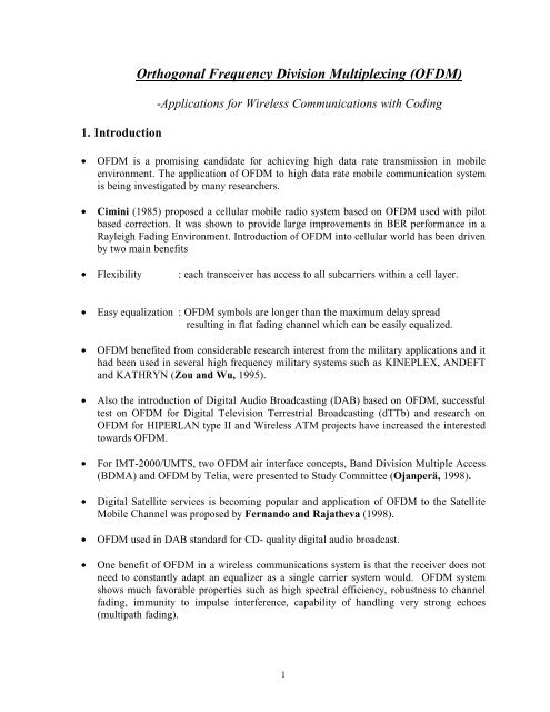
1. Introduction<br />
<strong>Orthogonal</strong> <strong>Frequency</strong> <strong>Division</strong> <strong>Multiplexing</strong> (<strong>OFDM</strong>)<br />
-Applications for Wireless Communications with Coding<br />
• <strong>OFDM</strong> is a promising candidate for achieving high data rate transmission in mobile<br />
environment. The application of <strong>OFDM</strong> to high data rate mobile communication system<br />
is being investigated by many researchers.<br />
• Cimini (1985) proposed a cellular mobile radio system based on <strong>OFDM</strong> used with pilot<br />
based correction. It was shown to provide large improvements in BER performance in a<br />
Rayleigh Fading Environment. Introduction of <strong>OFDM</strong> into cellular world has been driven<br />
by two main benefits<br />
• Flexibility<br />
: each transceiver has access to all subcarriers within a cell layer.<br />
• Easy equalization : <strong>OFDM</strong> symbols are longer than the maximum delay spread<br />
resulting in flat fading channel which can be easily equalized.<br />
• <strong>OFDM</strong> benefited from considerable research interest from the military applications and it<br />
had been used in several high frequency military systems such as KINEPLEX, ANDEFT<br />
and KATHRYN (Zou and Wu, 1995).<br />
• Also the introduction of Digital Audio Broadcasting (DAB) based on <strong>OFDM</strong>, successful<br />
test on <strong>OFDM</strong> for Digital Television Terrestrial Broadcasting (dTTb) and research on<br />
<strong>OFDM</strong> for HIPERLAN type II and Wireless ATM projects have increased the interested<br />
towards <strong>OFDM</strong>.<br />
• For IMT-2000/UMTS, two <strong>OFDM</strong> air interface concepts, Band <strong>Division</strong> Multiple Access<br />
(BDMA) and <strong>OFDM</strong> by Telia, were presented to Study Committee (Ojanperä, 1998).<br />
• Digital Satellite services is becoming popular and application of <strong>OFDM</strong> to the Satellite<br />
Mobile Channel was proposed by Fernando and Rajatheva (1998).<br />
• <strong>OFDM</strong> used in DAB standard for CD- quality digital audio broadcast.<br />
• One benefit of <strong>OFDM</strong> in a wireless communications system is that the receiver does not<br />
need to constantly adapt an equalizer as a single carrier system would. <strong>OFDM</strong> system<br />
shows much favorable properties such as high spectral efficiency, robustness to channel<br />
fading, immunity to impulse interference, capability of handling very strong echoes<br />
(multipath fading).<br />
1
• The mobile radio channel suffers from multipath propagation and the channel is time<br />
variant, depending on the speed of the mobile station. Thus, Forward Error Correcting<br />
schemes should be used in <strong>OFDM</strong> system to improve the performance better. Application<br />
of suitable coding scheme to <strong>OFDM</strong> provides a diversity effect through exploitation of<br />
the multipath nature of the fading channel.<br />
Problems<br />
• There are some obstacles in using <strong>OFDM</strong> in transmission system in contrast to its<br />
advantages. A major obstacle is that the <strong>OFDM</strong> signal exhibits a very high Peak to<br />
Average Power Ratio (PAPR).<br />
• Therefore, RF power amplifiers should be operated in a very large linear region.<br />
Otherwise, the signal peaks get into non-linear region of the power amplifier causing<br />
signal distortion. This signal distortion introduces intermodulation among the subcarriers<br />
and out of band radiation. Thus, the power amplifiers should be operated with large<br />
power back-offs. On the other hand, this leads to very inefficient amplification and<br />
expensive transmitters. Thus, it is highly desirable to reduce the PAPR.<br />
• The other limitation of <strong>OFDM</strong> in many applications is that it is very sensitive to<br />
frequency errors caused by frequency differences between the local oscillators in the<br />
transmitter and the receiver.<br />
• Carrier frequency offset causes a number of impairments including attenuation and<br />
rotation of each of the subcarriers and intercarrier interference (ICI) between subcarriers.<br />
In the mobile radio environment, the relative movement between transmitter and receiver<br />
causes Doppler frequency shifts, in addition, the carriers can never be perfectly<br />
synchronized. These random frequency errors in <strong>OFDM</strong> system distort orthogonality<br />
between subcarriers and thus intercarrier interference (ICI) occurs. A Number of methods<br />
have been developed to reduce this sensitivity to frequency offset.<br />
2
2. <strong>OFDM</strong> Overview<br />
• The <strong>Orthogonal</strong> <strong>Frequency</strong> <strong>Division</strong> <strong>Multiplexing</strong> (<strong>OFDM</strong>) transmission scheme is the<br />
optimum version of the multicarrier transmission scheme. In the past, as well as in the<br />
present, the <strong>OFDM</strong> is refered in the literature Multi-carrier, Multi-tone and Fourier<br />
Transform.<br />
• The concept of using parallel data transmission and frequency multiplexing was<br />
published in the mid 1960s. After more than thirty years of research and development,<br />
<strong>OFDM</strong> has been widely implemented in high speed digital communications. Due to<br />
recent advances of digital signal Processing (DSP) and Very Large Scale Integrated<br />
circuit (VLSI) technologies, the initial obstacles of <strong>OFDM</strong> implementation such as<br />
massive complex computation, and high speed memory do not exist anymore.<br />
• The use of Fast Fourier Transform (FFT) algorithms eliminates arrays of sinusoidal<br />
generators and coherent demodulation required in parallel data systems and makes the<br />
implementation of the technology cost effective (Weinstein and Ebert, 1971).<br />
• The <strong>OFDM</strong> concept is based on spreading the data to be transmitted over a large number<br />
of carriers, each being modulated at a low rate. The carriers are made orthogonal to<br />
each other by appropriately choosing the frequency spacing between them.<br />
• In contrast to conventional <strong>Frequency</strong> <strong>Division</strong> <strong>Multiplexing</strong>, the spectral overlapping<br />
among sub-carriers are allowed in <strong>OFDM</strong> since orthogonality will ensure the subcarrier<br />
separation at the receiver, providing better spectral efficiency and the use of<br />
steep bandpass filter was eliminated.<br />
• <strong>OFDM</strong> transmission system offers possibilities for alleviating many of the problems<br />
encountered with single carrier systems. It has the advantage of spreading out a frequency<br />
selective fade over many symbols. This effectively randomizes burst errors caused by<br />
fading or impulse interference so that instead of several adjacent symbols being<br />
completely destroyed, many symbols are only slightly distorted.<br />
• This allows successful reconstruction of majority of them even without forward error<br />
correction. Because of dividing an entire signal bandwidth into many narrow subbands,<br />
the frequency response over individual subbands is relatively flat due to subband are<br />
smaller than coherence bandwidth of the channel. Thus, equalization is potentially<br />
simpler than in a single carrier system and even equalization may be avoided altogether if<br />
differential encoding is implemented.<br />
• The orthoganality of subchannles in <strong>OFDM</strong> can be maintained and individual<br />
subchannels can be completely separated by the FFT at the receiver when there are no<br />
intersymbol interference (ISI) and intercarrier interference (ICI) introduced by the<br />
transmission channel distortion.<br />
3
• Since the spectra of an <strong>OFDM</strong> signal is not strictly band limited, linear distortions such as<br />
multipath propagation causes each subchannel to spread energy into the adjacent<br />
channels and consequently cause ISI.<br />
• One way to prevent ISI is to create a cyclically extended guard interval, where each<br />
<strong>OFDM</strong> symbol is preceded by a periodic extension of the signal itself. When the guard<br />
interval is longer than the channel impulse response or multipath delay, the ISI can be<br />
eliminated.<br />
• By using time and frequency diversity, <strong>OFDM</strong> provides a means to transmit data in a<br />
frequency selective channel. However, it does not suppress fading itself. Depending on<br />
their position in the frequency domain, individual subchannels could be affected by<br />
fading.<br />
• This requires the use of channel coding to further protect transmitted data. Coded <strong>OFDM</strong><br />
combined with frequency and time interleaving is considered the most effective means for<br />
a frequency selective fading channel (Shelswell, 1995).<br />
4
x bits<br />
d 0<br />
Serial<br />
Data I/P<br />
Serial-to-<br />
Parallel<br />
Converter<br />
.<br />
.<br />
d 1<br />
Signal<br />
Mapper .<br />
IFFT .<br />
.<br />
.<br />
P/S<br />
Guard<br />
Interval<br />
Insertion<br />
D/A<br />
LPF<br />
Serial<br />
Data<br />
O/P<br />
P/S<br />
x bits<br />
.<br />
.<br />
d N-1<br />
Down<br />
Converter Channel<br />
d 0<br />
d 1<br />
Signal<br />
One<br />
Mapper .<br />
tap<br />
.<br />
FFT<br />
. Equ.<br />
d 1<br />
.<br />
d N-1<br />
S/P<br />
Up<br />
Converter<br />
Guard<br />
Interval<br />
Removal<br />
LPF<br />
A/D<br />
Figure 2.1 General <strong>OFDM</strong> System (Zou and Wu, 1995)<br />
• Figure 2.1 illustrates the process of a typical <strong>OFDM</strong> system.<br />
• The incoming serial data is first converted from serial to parallel and grouped into x bits<br />
each to form a complex number. The complex numbers are modulated in a baseband<br />
fashion by the IFFT. And converted back to serial data for transmission.<br />
• A guard interval is inserted between symbols to avoid intersymbol interference (ISI)<br />
caused by multipath distortion. The discrete symbols are converted to analog and lowpass<br />
filtered for RF up-conversion.<br />
• The receiver performs the inverse process of the transmitter. One tap equalizer is used to<br />
correct channel distortion. The tap coefficients of the filter are calculated based on<br />
channel information (Zou and Wu, 1995).<br />
5
2.2 <strong>OFDM</strong> in Cellular Mobile System<br />
• Severe multipath propagation, arising from multiple scattering by buildings and other<br />
structures in the vicinity of a mobile unit, makes the design of a mobile communication<br />
channel very challenging.<br />
• The scattering produces rapid random amplitude and phase variations in the received<br />
signal as the vehicle moves in the multipath field. In addition, the whole motion<br />
introduces a Doppler shift, which causes a broadening of the signal spectrum.<br />
• Since <strong>OFDM</strong> has the property of robustness to multipath propagation and other favorable<br />
properties, it is likely to be considered for mobile communication systems. Cimini<br />
(1985) proposed a cellular mobile radio system based on <strong>OFDM</strong>.<br />
• <strong>OFDM</strong> combined with CDMA and TDMA is being investigated by many researchers.<br />
Various Multicarrier (MC) transmission schemes have been recently introduced into<br />
Direct Sequence- Code <strong>Division</strong> Multiple Access(DS-CDMA) systems to acquire<br />
benefits such as higher rate data transmission, bandwidth efficiency, frequency diversity<br />
and interference reduction.<br />
• A Multicarrier DS-CDMA system with adaptive frequency hopping system has shown<br />
significant performance improvement over some existing systems in terms of the average<br />
BER performance (Elvino 1996). Covolutional coded CDMA system combined with<br />
<strong>OFDM</strong> allows to perform maximum likelihood detection (MLD), to use the spectrum in<br />
an efficient way, to exploit frequency diversity and time diversity provided by channel<br />
coding and to retain many advantages of a CDMA system (Fazel and Papke,1998).<br />
Multicarrier technique has been proposed for the downlink in Wideband cdmaOne<br />
approach in IMT-2000/UMTS (Ojanperä and Prasad, 1998).<br />
• Rohling and Grunheid (1996) analyzed <strong>OFDM</strong> transmission technique in combination<br />
with a TDMA/TDD multiple access schemes for a cellular mobile communication<br />
system. Space-time coded <strong>OFDM</strong> scheme was proposed for providing high data rate<br />
wireless communication over wideband channels, capable of reliable transmission at<br />
relatively lower SNR in a variety of delay profiles making it a robust alternative<br />
(Agrawal, Tarokh, Naguib and Seshadri, 1998).<br />
• <strong>Orthogonal</strong> <strong>Frequency</strong> <strong>Division</strong> Multiple Access (<strong>OFDM</strong>A) system for mobile<br />
communication was proposed by Nogueroles, Bossert, Donder and Zyablov (1998)<br />
based on Multicarrier FDMA, where each user has a set of randomly selected<br />
subchannels. Baum (1998) proposed a new air interface concept for future <strong>OFDM</strong> based<br />
cellular systems called Synchronous Coherent <strong>Orthogonal</strong> <strong>Frequency</strong> <strong>Division</strong><br />
<strong>Multiplexing</strong> (SC-<strong>OFDM</strong>). It is based on a combination of synchronized cells, orthogonal<br />
pilot codes and cyclic extension which is large enough to absorb both delay spread and<br />
inter-cell propagation delay.<br />
• Cimini (1997) proposed an asymmetric wireless Internet Service for mobile users in<br />
macrocells with peak downlink bit rates of 1 to 2 Mbps. This technique, for the high<br />
speed downlink, <strong>OFDM</strong> with transmit and receive antenna diversity and Reed Solomon<br />
6
coding, is a promising approach to overcome the link budget and dispersive-fading<br />
limitation of the cellular mobile radio environment. For IMT-2000/UMTS, two <strong>OFDM</strong><br />
air interface concepts, BDMA and <strong>OFDM</strong> by Telia, were presented to Study Committee<br />
(Ojanperä,1998).<br />
Peak to Average power Ratio (PAPR)<br />
• <strong>OFDM</strong> has several properties, which make it an attractive modulation scheme for high<br />
speed transmission links. However, one major difficulty is its large Peak to Average<br />
Power Ratio (PAPR).<br />
• These large peaks cause saturation in power amplifiers, leading to intermodulation<br />
products among the subcarriers and disturbing out of band energy. Therefore, it is<br />
desirable to reduce the PAPR.<br />
• To reduce the PAPR, several techniques have been proposed such as clipping, coding ,<br />
peak windowing, Tone Reservation and Tone Injection. But, most of these methods are<br />
unable to achieve simultaneously a large reduction in PAPR with low complexity, with<br />
low coding overhead, without performance degradation and without transmitter receiver<br />
symbol handshake.<br />
• The complex envelope of the <strong>OFDM</strong> signal, consisting of N carriers is given by (Müller<br />
and Huber, 1997),<br />
S<br />
total<br />
=<br />
∞<br />
∑<br />
k=−∞<br />
N−1<br />
∑<br />
n=<br />
0<br />
a<br />
n<br />
, k . g(<br />
t − kT).<br />
e<br />
2π<br />
jn t<br />
T<br />
(2.1)<br />
Where g(t) is rectangular pulse of duration T and T is <strong>OFDM</strong> symbol duration.<br />
• Peak to Average power Ratio is defined by (Müller and Huber, 1997),<br />
PAPR<br />
max S(<br />
t)<br />
t∈[0,<br />
T ]<br />
= (2.2)<br />
2<br />
ε{<br />
S(<br />
t)<br />
2<br />
}<br />
where ε {⋅ } denotes the expectation.<br />
7
• From the central limit theorem, for large values of N , the real and imaginary values of<br />
S(t) become Gaussian distributed. The amplitude of the <strong>OFDM</strong> signal therefor has a<br />
Rayleigh distribution with zero mean and a variance of N times the variance of one<br />
complex sinusoid.<br />
• Assuming the samples to be mutually uncorrelated, the cumulative distribution function<br />
for the Peak Power per <strong>OFDM</strong> symbol can be given by (Müller and Huber, 1997),<br />
−γ<br />
N<br />
( 1−<br />
(1 − e )<br />
Pr{ PAPR γ } = )<br />
> (2.3)<br />
From this, it is seen that large PAPR occurs only infrequently.<br />
• In literature, two kinds of approaches are investigated which assure that the transmitted<br />
<strong>OFDM</strong> signal does not exceed the amplitude A 0 if a given back off is used.<br />
• The first method makes use of redundancy in such a way that any data sequence leads to<br />
the magnitude of <strong>OFDM</strong> signal greater than A 0 or that at least the probability of higher<br />
amplitude peaks is greatly reduced. This approach does not result in interference of the<br />
<strong>OFDM</strong> signal.<br />
• In the second approach, the <strong>OFDM</strong> signal is manipulated by a correcting function, which<br />
eliminates the amplitude peaks. The out of band interference caused by the correcting<br />
function is zero or negligible. However, interference of the <strong>OFDM</strong> signal itself is<br />
tolerated to a certain extent.<br />
• Peak to Average power Ratio effect is described by Peak Envelop and Crest-Factor (CF)<br />
which is defined as the square root of Peak to Average Power Ratio. Here, we will refer it<br />
as Peak to Average power Ratio (PAPR). In the following section, some significant<br />
methods to reduce PAPR are described.<br />
• Block Coding<br />
A block coding scheme for reduction of PAPR proposed by Jones, Wilkinson and Barton<br />
(1994) is to find code words with minimum PAPR from a given set of code words and to<br />
map the input data blocks of these selected code words. Thus, it avoids transmitting the code<br />
words which generates high Peak Envelop Power. But, this reduction of PAPR is at the<br />
expense of a decrease in coding rate. It has 2.48 dB with ¾ rate block code for four carrier<br />
signal. For large number of carriers, necessary code sets exist but encoding and decoding is<br />
also difficult task. It is not suitable for higher order bit rates or large number of carriers.<br />
8
• M sequences<br />
The use of m-sequences for PAPR reduction is proposed by Li and Ritcey (1997). This is<br />
done by mapping a block of m input bits to an m-sequences [C 0 …..C N-1 ] of length N=2 m -1.<br />
This results in a code rate of (m/2 m -1). The m-sequences are a class of (2 m -1,m) cyclic codes<br />
obtained from a primitive polynomial of degree m over GF(2). Tellambura (1997) showed<br />
that the achievable PAPR is only between 5dB to 7.3 dB for m between 3 and 10. The<br />
problem with this approach is the extremely low rate for large values of m.<br />
• Selective Scrambling<br />
Eetvelt, Wade and Tomlinson (1996) proposed this technique to reduce PAPR. The method<br />
is to form four code words in which the first two bits are 00,01,10 and 11 respectively. The<br />
message bits are first scrambled by four fixed cyclically inequivalent m-sequences. Then the<br />
one with the lowest PAPR is selected and one of the pair of bits defined earlier is appended at<br />
the beginning of the selected sequence. At the receiver, these first two bits are used to select<br />
the suitable descrambler. When a scrambled binary sequence with high proportion of 1s or 0s<br />
is applied to N- point IFFT <strong>OFDM</strong> modulator, it will give a signal with high PAPR. A<br />
scrambled binary sequence of length 2N with a Hamming weight close to N will often<br />
generate low PAPR. Selecting structured scrambled sequence is critical. PAPR is typically<br />
reduced to 2% of the maximum possible value while incurring negligible redundancy in a<br />
practical system.<br />
• Clipping and Filtering<br />
Deliberate clipping is a simple approach and, since the large peaks occur with a very low<br />
probability, clipping could be on effective technique for the reduction of the PAPR (O'Neill<br />
and Lopes, 1995). However, clipping is a nonlinear process and may cause significant inband<br />
distortion, which degrades the bit error rate performance, and out of band noise, which<br />
reduces the spectral efficiency. Filtering after clipping can reduce the spectral splatter but<br />
may also cause some peak regrowth (Li and Cimini, 1998). If digital signals are clipped<br />
directly, the resulting clipping noise will all fall in-band and can not be reduced by filtering.<br />
To avoid this aliasing problem, oversample each <strong>OFDM</strong> block by padding the original input<br />
with zeros and taking a longer IFFT. Filtering after clipping is required to reduce the out of<br />
band clipping noise. The other approach to clipping is to use Forward Error Correcting codes<br />
and bandpass filtering with clipping (Wulich and Goldfeld, 1999). This method improves<br />
the bit error rate performance and spectral efficiency.<br />
• Peak Windowing<br />
The simplest way to reduce the PAPR is to clip the signal, but this significantly increases the<br />
out of band radiation. A different approach is to multiply large signal peak with a Gaussian<br />
shaped window proposed by Pauli and Kuchenbeeker (1997). But, in fact any window can<br />
be used, provided it has good spectral properties (Van Nee and Wild, 1998). Since the<br />
<strong>OFDM</strong> signal is multiplied with several of these windows the resulting spectrum is a<br />
convolution of the original <strong>OFDM</strong> spectrum with the spectrum of the applied window. So,<br />
9
ideally the window should be as narrow band as possible. On the other hand, the window<br />
should not be too long in the time domain, because that implies that many signal samples are<br />
affected, which increases the bit error ratio. Examples of suitable window functions are the<br />
Cosine, Kaiser and Hamming window. Van Nee and Wild (1998) showed that PAPR could<br />
be achieved independent from number of sub-carriers, at the cost of a slight increase in BER<br />
and out of band radiation.<br />
• Bandwidth Efficient Reduction of the Crest Factor (BERC)<br />
This procedure, the BERC scheme proposed by Pauli and Kuchenbeeker (1998) is to<br />
multiply the envelope m E (t) with a weighting function b(t). Thus, we have<br />
m<br />
( t)<br />
m ( t).<br />
b ( t)<br />
E = E<br />
(2.4)<br />
The function b(t) is composed of a sum of Gaussian pulses.<br />
where<br />
g(<br />
t)<br />
= e<br />
( t)<br />
= 1−<br />
∑ ∞ an.<br />
g(<br />
t − t n<br />
n=<br />
−∞<br />
(2.5)<br />
2<br />
−γ<br />
t<br />
b )<br />
Gaussian pulses are chosen because they are optimally concentrated both in time and<br />
frequency domain. t n denotes the position of a local maximum of the envelope m E (t) above a<br />
certain threshold S that is normalized to the root mean square value m Eff . The coefficients a n<br />
are chosen in way that the envelop m E<br />
(t)<br />
does no longer cross the threshold S<br />
a<br />
n<br />
1−<br />
S.<br />
m<br />
m<br />
E<br />
Eff<br />
= (2.6)<br />
( t)<br />
The factor γ is used for the optimization of the weighting function. A small value for γleads<br />
to narrow band weighting function and higher bit error rate follows.<br />
• Additive Correcting Function<br />
Proposed by May and Rohling (1998), this approach is similar to peak windowing but<br />
additive correction function is used instead of multiplicative correction function. <strong>OFDM</strong><br />
signal is modified in such a way that given amplitude threshold of the signal is not exceeded<br />
after the correction. With the restriction that the correcting function dose not causes any out<br />
of band interference, the correcting function has been given with minimal power and thus<br />
causes minimal interference power within the <strong>OFDM</strong> band.<br />
The corrected signal can be written as,<br />
10
c ( t)<br />
S(<br />
t)<br />
+ k(<br />
t)<br />
where k t)<br />
= ∑ A . g(<br />
t − t )<br />
= (2.7)<br />
( n n<br />
A<br />
n<br />
S(<br />
t<br />
).<br />
S(<br />
t<br />
)<br />
n<br />
= −( S(<br />
t)<br />
− A0<br />
(2.8)<br />
n )<br />
This correction limits the signal S(t) to A o at the positions t n of amplitude peaks.<br />
jπBt<br />
g( t)<br />
≈ sin c(π Bt).<br />
e<br />
(2.9)<br />
• This function can correct an amplitude peak in the <strong>OFDM</strong> signal with minimal<br />
interference of the signal without any out of band interference. For practical application,<br />
however, the extent of the sinc function in time must be limited by windowing.<br />
• Selected Mapping (SLM)<br />
Bäuml, Fischer and Huber (1996) proposed this method to reduce PAPR for a wide<br />
range of applications. Because of the statistical independence of the carriers, the<br />
corresponding time domain samples v[k] ,k=1,… .D in the equivalent complex valued<br />
lowpass domains are approximately Gaussian distributed. This results in a high peak to<br />
average power ratio.<br />
Because of varying assignment of data to the transmit signal, this method is called<br />
“Selected Mapping”. The core is to choose one particular signal, which exhibits some desired<br />
properties out of N signal representing the same information. Generating <strong>OFDM</strong> frames<br />
representing the same information is as follows.<br />
Define N distinct vectors P (n) = [ P 1 (n) …..P D (n) ] with<br />
P<br />
( n)<br />
φ µ<br />
( n)<br />
j<br />
µ = e<br />
(2.10)<br />
( n)<br />
where φ µ ∈[0,2π<br />
] µ=1… .D and n=1… ..N<br />
After mapping the information to the carriers V[µ] each <strong>OFDM</strong> frame is multiplied<br />
carrierwise with the N vectors P (n) , resulting in a set of N different frames with components<br />
( n)<br />
( n)<br />
jφ µ<br />
V<br />
[ µ ] = V[<br />
µ ]. e<br />
(2.11)<br />
11
• Then all N frames are transformed into the time domain and the one with the lowest<br />
PAPR is selected for transmission. To recover data, the receiver has to know which<br />
vector P (n) has actually used and the number n of the vector is transmitted to the receiver<br />
as side in formation. This method can be used for arbitrary number of carriers and any<br />
signal constellation. It provides significant gain against moderate additional complexity.<br />
• Partial Transmit Sequence(PTS)<br />
The main idea of this scheme proposed by Müller and Huber (1997) is that the<br />
(v)<br />
subcarier vector A µ is partitioned into V pairwise disjoint sub blocks A µ ; v=1,… ,V<br />
All subcarrier positions in<br />
to zero so that<br />
A<br />
(v)<br />
A µ , which are already represented in another subblock, are set<br />
= ∑<br />
V ( v)<br />
µ Aµ<br />
(2.12)<br />
v=<br />
1<br />
Modified subcarrier vector = ∑<br />
V ( v ) ( v)<br />
Aµ bµ<br />
. Aµ<br />
(2.13)<br />
v=<br />
1<br />
(v)<br />
represents the same information as A µ , if the set { b µ , v=1,… ..,V}is known for each µ.<br />
b µ is complex rotation factors with = 1<br />
( v0<br />
b µ for v=1,… …,V<br />
( v)<br />
( v)<br />
and partial transmit sequence is a µ = IDFT{<br />
Aµ<br />
}<br />
(2.14)<br />
Based on them, a peak value optimization is performed by suitably choosing the free<br />
(v)<br />
(v) (v)<br />
parameters b µ such that PAPR is minimized for b µ . The b µ may be chosen with<br />
continuous valued phase angel.<br />
Then, the optimum transmit sequence is<br />
( v ) ( v)<br />
µ a<br />
(2.15)<br />
a = ∑bµ<br />
. µ<br />
• This scheme requires that the receiver has knowledge about the generation of the<br />
(v)<br />
transmitted <strong>OFDM</strong> in symbol period µ. Thus, the set with all rotation factors b µ has<br />
to be transmitted to the receiver so that this one can derotate the subcarriers appropriately<br />
12
. This side information is the redundancy introduced by PTS. This is the distortionless<br />
scheme and it works with arbitrary and any type of modulation on them while inserting<br />
only little redundancy.<br />
• Tone Reservation<br />
Proposed by Tellado and Cioffi (1998), the PAPR is reduced by adding time domain<br />
signals to the data sequences that lay in disjoint frequency space to the multicarrier data<br />
symbols. With this formation, optimizing the time domain signal leads to a convex<br />
optimization problem that can be transformed into a linear program (LP). Solving the LP<br />
exactly leads to PAPR reduction of 6-10dB, but a simple gradient algorithm could achieve<br />
most of this reduction after a few iterations. These additive signals can be easily removed<br />
from the received signal without transmitter receiver symbol handshake.<br />
If we do not transmit data on all tone, i.e. some values of data vector are zero, we can<br />
use these values for reducing PAPR. If data vector Xj=0 for j ∈ {j 1 ,…j L }, then the transmitter<br />
can add any vector c that satisfies, c j =0 for j ∉ {j 1 …j L } to the data vector and remove it at<br />
the receiver.<br />
IDFT (X+C) = Q(X+C) =x+QC =x+c where Q denotes IDFT matrix.<br />
2<br />
x + c<br />
∞<br />
PAR(<br />
x + c)<br />
=<br />
(2.16)<br />
2<br />
ε{<br />
x }<br />
2<br />
N<br />
To minimize the PAPR of (x+c), we must compute the vector c* that minimizes the<br />
maximum peak value.<br />
x + c = x + Qˆ Cˆ<br />
min min<br />
(2.17)<br />
c<br />
∞<br />
c ∞<br />
Using gradient algorithm iteratively, PAPR can be reduced. This algorithm has<br />
complexity, O(N) and can be applied to any number of carriers. But, there is little increases<br />
in transmit power and little data rate loss.<br />
13
Carrier <strong>Frequency</strong> Offset<br />
• Another limitation of <strong>OFDM</strong> in many applications is that it is very sensitive to frequency<br />
errors caused by frequency differences between the local oscillators in the transmitter and<br />
the receiver. Carrier frequency offset causes a number of impairments.<br />
• There are two deleterious effects caused by frequency offset; one is the reduction of<br />
signal amplitude in the output of the filters matched to each of the carriers and the second<br />
is the introduction of inter carrier interference (ICI) from the other carriers which are<br />
now no longer orthogonal to the filter.<br />
• Because, in <strong>OFDM</strong>, the carriers are inherently closely spaces in frequency compared to<br />
the channel bandwidth, the tolerable frequency offset becomes a very small fraction of<br />
the channel bandwidth.<br />
• Maintaining sufficient open loop frequency accuracy can become difficult in links, such<br />
as satellite links with multiple frequency translation or mobile digital radio links that<br />
may also introduce significant Doppler shift. <strong>OFDM</strong> is orders of magnitude more<br />
sensitive to frequency offset and phase noise than single carrier system (Pollet, Van<br />
Bladel and Moeneclaey, 1995).<br />
• ICI counter measures are divided into three groups.<br />
• The most commonly used method is frequency-domain equalization, which uses training<br />
signals (Ahn and Lee, 1993).<br />
• The time-domain windowing method can also reduce ICI through multiplying the<br />
transmitted time-domain signals by a well-designed windowing function (Li and Stette,<br />
1995).<br />
• The third method is called the ICI self-cancellation scheme (Zhao and Häggman, 1996).<br />
• A main feature of these methods is that bandwidth efficiency might be reduced either by<br />
training signals or by using redundant subcarriers Moose (1994) described the maximum<br />
likelihood estimator of the carrier frequency offset, based on the observation of two<br />
consecutive and identical symbols.<br />
• Li and Stette (1995) proposed a Windowing method to reduce ICI by cyclically<br />
extending by v samples the time domain signal associated with each symbol. The whole<br />
of the resulting signal is then shaped with the window function. It is important to note<br />
that DFT transform in the receiver is N point whereas that in the transmitter is N/2 point.<br />
If v< N/2, then the signal corresponding to each symbol is zero padded at the receiver to<br />
give length N.<br />
14
• The outputs of the DFT with even numbered subscripts, in which actual data is<br />
modulated in transmitter, are used as estimates of the transmitted data and the odd<br />
numbered ones are discarded. Because not all of the received signal power is being used<br />
in generating data estimates, the method has a reduced overall SNR compared with<br />
<strong>OFDM</strong> without windowing. A number of different windows, including the Hanning<br />
window (Gudmundson and Anderson, 1996), windows satisfying the Nyquist criterion,<br />
and the Kaiser window (Muschallik, 1996) have been used to reduce ICI.<br />
• Zhao and Häggman (1996) proposed a method ,called “Self ICI Cancellation”, for<br />
reducing sensitivity to frequency errors. The method maps the data to be transmitted onto<br />
adjacent pairs of subcarriers with a 180-phase difference between them rather than onto<br />
single subcarriers. The disadvantage of this method is that it is less bandwidth efficient as<br />
two subcarriers are used to transmit one complex value.<br />
• Armstrong (1999) proposed a method based on self ICI cancellation method to improve<br />
the SNR while ICI is reduced. He showed that by mapping data onto larger groups of<br />
subcarriers, higher order ICI cancellation could be achieved.<br />
• Zhao, Leclercq and Häggman (1998) proposed a Correlative Coding between signals<br />
modulated on subsequent subcarriers to compress ICI in <strong>OFDM</strong> systems. They showed<br />
that carrier to interference power ratio is increased by 3.5 dB without decreasing<br />
bandwidth efficiency or increasing system complexity.<br />
15
3. SYSTEM MODEL<br />
3.1 Configuration<br />
• Block diagram of lowpass equivalent representation of the overall simulation model is<br />
shown in Figure 3.1.<br />
TRANSMITTER<br />
x bits<br />
Random<br />
Data<br />
Generator<br />
Coding<br />
S/P<br />
Converter<br />
.<br />
.<br />
Multicarrier<br />
Modulator<br />
.<br />
. window<br />
-in<br />
P/S<br />
Con.<br />
MOBILE RADIO CHANNEL<br />
Rayleigh Fading<br />
Channel<br />
Delay<br />
RECEIVER<br />
AWGN<br />
x bits<br />
Comparator<br />
Decoding<br />
P/S<br />
Converter<br />
.<br />
.<br />
Multicarrier<br />
Demodulator<br />
.<br />
. S/P<br />
Con.<br />
BER Out put<br />
Figure 3.1 Block Diagram of Lowpass Equivalent System Model<br />
(based on Zou and Wu, 1995)<br />
16
3.2 Transmitter Section<br />
Convolutional Code<br />
• In this study, the following convolutional encoder for (2,1,6) code with constraint length<br />
seven considered.<br />
+<br />
Input<br />
T<br />
T<br />
T<br />
T<br />
T<br />
T<br />
Output<br />
+<br />
Figure 3.2 ½ Rate Linear Convolutional Encoder with Constraint Length 7<br />
The Generator matrices for the encoder shown in Figure 3.2, is given by,<br />
G =[ 1 1 0 1 1 0 1 , 1 0 0 1 1 1 1 ] (3.1)<br />
or g 11 =[ 1 1 0 1 1 0 1 ]<br />
g 12 =[ 1 0 0 1 1 1 1 ]<br />
The two outputs are read into a serial data stream.<br />
QPSK Modulation<br />
QSPK modulation is a bandwidth efficient simple modulation scheme widely used in<br />
digital transmission systems. It has been proposed to use in Third Generation wireless<br />
communication system. The QPSK modulator is shown in Figure 3.3 and corresponding<br />
signal constellation diagram is shown in Figure 3.4.<br />
17
cos w c<br />
t<br />
a i<br />
X<br />
Binary input<br />
R bits/s<br />
Store two<br />
bits<br />
+<br />
b i<br />
X<br />
QPSK out put<br />
R/2 symbols /s<br />
1/T switch<br />
T=2/R<br />
sin w c<br />
t<br />
Figure 3.3 QPSK Modulator<br />
I m<br />
01<br />
00<br />
R e<br />
11 10<br />
Figure 3.4 QPSK Signal constellations<br />
FFT Implementation<br />
• In order to combat a multipath delay spread channel, the guard interval for the <strong>OFDM</strong><br />
signal should be longer than the multipath delay spread, τ<br />
max<br />
(Ziemer and Wickert,<br />
1997).<br />
δ . s ≥τ max<br />
t (3.2)<br />
Where δ is the fraction of the signaling interval, that is devoted to guard time and<br />
t s T + T T is guard interval and T is <strong>OFDM</strong> symbol duration.<br />
= ∆ where ∆<br />
• From these design criteria, the following equation can be derived to calculate the number<br />
of subcarriers (Ziemer and Wickert, 1997).<br />
18
R<br />
τ<br />
( mN)<br />
b max<br />
min = (3.3)<br />
δ . Rc<br />
where R c is the code rate, R b is the bit rate, m is the bits per subcarrier and N is number of<br />
subcarriers.<br />
N=128 was selected for the analysis in order to employ any modulation scheme. Thus, the<br />
size of the FFT is 128.<br />
<strong>OFDM</strong> symbol duration can be expressed as,<br />
T<br />
( mN)<br />
R<br />
c<br />
= (3.4)<br />
Rb<br />
To satisfy orthoganality of subcarriers,<br />
T = NTs<br />
(3.5)<br />
where T<br />
s<br />
is sampling rate and can be expressed as,<br />
mRc<br />
T s = (3.6)<br />
R<br />
b<br />
Oversampling<br />
• When calculating the PAPR, we have to consider the actual time domain signal that is in<br />
analog form. The IFFT outputs, which are symbol spaced sampling values, will miss<br />
some of the signal peaks.<br />
• If we calculate PAPR by using these sample values, then the calculated PAPR is less than<br />
the actual PAPR. This is an optimistic result and will not illustrate the real situation.<br />
However, they are enough for signal reconstruction.<br />
• To account for this issue, oversampling is performed by low pass filtering the IFFT signal<br />
and then sampled at a higher rate. Now, the increased samples are close to the real analog<br />
signal and calculation of PAPR based on these samples will give the true PAPR.<br />
19
3.3 Proposal to Reduce PAPR<br />
Motivation:<br />
• PAPR increases when number of subcarrier increases. It can be shown that for a<br />
baseband <strong>OFDM</strong> signal with N subcarriers has a PAPR=N 2 /N =N (Leonard J. Cimini,<br />
1997). One way to reduce PAPR is reduce the number of subcarriers as low as possible<br />
even when a PAPR reduction scheme is employed.<br />
• The simplest way to reduce the PAPR is to clip the <strong>OFDM</strong> signal before amplification<br />
(O’Neill and Lopes, 1995). It is possible to remove the peaks at the cost of slight amount<br />
of self-interference since large peaks occur with very low probability.<br />
• However, clipping is a nonlinear process and may cause significant in-band distortion,<br />
which degrades the bit-error-rate (BER) performance, and out of band noise, which<br />
reduces the spectral efficiency. Filtering after clipping can reduce the spectral splatter and<br />
it is a promising technique to reduce PAPR (Li and Cimini, 1998). Another approach is<br />
the clipping with Forward Error Correcting codes. Wulich and Goldfeld (1999) showed<br />
the improved performance in PAPR and spectral efficiency when clipping is used with a<br />
forward error correcting code.<br />
• A different approach to clipping is peak windowing where large signal peaks are<br />
multiplied by certain window function, which has good spectral properties (Van Nee and<br />
Wild, 1998). Ideally, the window should be as narrowband as possible but it should not<br />
be too long in the time domain. Examples of suitable window functions are the Cosine,<br />
Kasier and Hamming window. The signal is no longer composed of orthogonal carriers<br />
after multiplying the <strong>OFDM</strong> signal by windowing function. Thus, there will be an<br />
increase in BER and out of band radiation.<br />
Methodology:<br />
• Among the existing methods, Peak Windowing exhibits good properties such as very<br />
simple to implement, independent of number of carriers, no affect in coding rate and<br />
large reduction in PAPR. In this study, peak windowing with forward error correcting<br />
codes will be analyzed since it may compensate the increase in BER and give better<br />
performance that can be implemented in a small inexpensive mobile unit. Then, we<br />
propose a method to be used with peak windowing to reduce the PAPR further.<br />
• Windowing parameters, window width and attenuation factor, should be selected such a<br />
way that it will reduce the PAPR. However, it is difficult to find a relationship between<br />
windowing parameters and PAPR since the PAPR is random. Generally, the window<br />
width should be small in order to avoid distorting many sample values and the attenuation<br />
20
factor should be selected by considering PAPR reduction and signal distortion. Further, it<br />
is necessary to relate <strong>OFDM</strong> parameters with peak windowing.<br />
• In this study, we consider peak windowing method, by defining clipping ratio. When<br />
clipping is employed to reduce PAPR, the <strong>OFDM</strong> signal is clipped whenever it exceeds a<br />
clip level, A. Normalized clipping level, which is called clipping ratio (CR), is defined as<br />
(Li and Cimini, 1998),<br />
A<br />
CR = (3.7)<br />
σ<br />
Where σ is the rms power of the <strong>OFDM</strong> signal and it can be shown that, for an <strong>OFDM</strong> signal<br />
with N subchannels, σ = N for a baseband signal and σ = N / 2 for a bandpass signal.<br />
(Li and Cimini, 1998).<br />
• <strong>OFDM</strong> signal is multiplied by the window function when the signal peak exceeds the<br />
clipping level. Unlike the clipping, the <strong>OFDM</strong> signal within the windowing width is<br />
modified. This results in a smoothed <strong>OFDM</strong> signal. The following modified Hanning<br />
window function is used in this study.<br />
1−<br />
w [ n]<br />
=<br />
c<br />
k<br />
c<br />
(0.5−<br />
0.5cos(2π<br />
n / M ))<br />
0<br />
0 ≤ n ≤ M<br />
otherwise<br />
(3.8)<br />
where k<br />
c<br />
is the attenuation factor of the window function.<br />
• The PAPR reduction is achieved at the expense of bit error rate (BER) performance<br />
degradation and the out of band radiation. On the other hand PAPR can not be reduced<br />
beyond a certain limit by removing peaks, as the average value of the <strong>OFDM</strong> signal, also<br />
decreases, which in turn increases the PAPR. This can be realized from the following<br />
definition of PAPR<br />
• One simple way to reduce PAPR further is increase the average value of the <strong>OFDM</strong><br />
signal. Here, we propose a method, called “Pre-amplification” to employ with Peak<br />
windowing to reduce the PAPR further.<br />
• Peak windowing method concerns only removing the peak values, which have low<br />
probability of occurrence. <strong>OFDM</strong> signal exhibits some low values, we will call it<br />
"bottoms", with low probability of occurrence, like peaks. By increasing these bottoms<br />
above certain level, the average value of <strong>OFDM</strong> signal can be shifted up. This results in<br />
PAPR reduction. Basically, this is like inverted windowing. Now, the sample values are<br />
amplified and thus we call it "Pre-amplification".<br />
21
• In Pre-amplification, output signal from peak windowing is multiplied by the modified<br />
window function when the signal falls below the bottom level. Like, peak windowing, the<br />
signal within the window width is modified. This will cause BER degradation and out of<br />
band radiation. We analyze these effects in this study. The following modified Hanning<br />
window function is used in this analysis.<br />
1+<br />
w [ n]<br />
=<br />
a<br />
k<br />
a<br />
(0.5−<br />
0.5cos(2π<br />
n / M ))<br />
0<br />
0 ≤ n ≤ M<br />
otherwise<br />
(3.10)<br />
where k<br />
a<br />
is the amplification factor of the window function.<br />
22
3.4 Channel Model<br />
• The typical mobile radio channel is one suffering from severe multipath fading and this<br />
leads to severe degradation of the bit error rate (BER) performance.<br />
• In an <strong>OFDM</strong> system, as the signals in each channel are of low flow rate, having larger<br />
symbol duration, channel can be considered as frequency flat. This is true when the<br />
coherence bandwidth of the channel is greater than the symbol rate.<br />
• But, the real channel is frequency selective and the <strong>OFDM</strong> system exhibits diversity<br />
effect in a frequency selective channel. This is the major benefit in using <strong>OFDM</strong><br />
system in a multipath fading channel.<br />
The impulse response of the multipath fading channel can be expressed as follows.<br />
L<br />
∑ − 1<br />
m<br />
m=<br />
0<br />
jφ<br />
h(<br />
t)<br />
= h e<br />
mδ<br />
( t −τ<br />
m<br />
)<br />
(3.11)<br />
where<br />
h m is Rayleigh distributed and m<br />
φ is uniformly distributed.<br />
Following assumptions are made before taking the frequency response of the impulse<br />
response in order to apply it in an <strong>OFDM</strong> system.<br />
1. The channel is static during an <strong>OFDM</strong> symbol duration.<br />
2. The delay between consecutive paths is equal to the sample duration (T).<br />
3. AWGN posses same statistical properties both in time and frequency domain.<br />
Then, the frequency response of the channel can be expressed as follows.<br />
H<br />
n<br />
nm<br />
− j2π<br />
= ∑ h N<br />
me<br />
n=0,1,… ….,N-1 (3.12)<br />
• The multipath channel is assumed to be a symbol spaced taped delay line model and<br />
characterized by a multipath intensity profile. For practical purposes, the tapped delay<br />
line channel model can be truncated at L taps given by (Proakis, 1995)<br />
⎡T<br />
max ⎤<br />
L =<br />
+ 1<br />
(3.13)<br />
⎢ T s ⎥<br />
23
where T max is the total multipath excess delay. Assuming a typical urban / suburban outdoor<br />
environment having 3µs multipath spread and T s<br />
= 0.5µ<br />
s , we can model the channel with L<br />
=7 taps.<br />
• The multipath intensity profile varies as physical channel changes with time. It is also<br />
varies when the receiver changes its relative position to the transmitter. Statistically, the<br />
different multipaths are assumed to follow exponentially decaying power delay profile.<br />
This can be realized by assigning different variances to noise sources of individual taps.<br />
The total average power of the channel is normalized to unity.<br />
L<br />
∑ − 1<br />
n=<br />
0<br />
2<br />
{ } =<br />
E α 1<br />
(3.14)<br />
n<br />
• Following exponential power delay profile is used to calculate average power of each<br />
taps.<br />
e<br />
−<br />
L<br />
∑ − 1<br />
n=<br />
0<br />
nT<br />
T<br />
d<br />
Q ( n)<br />
=<br />
(3.15)<br />
nTc<br />
e<br />
−<br />
c<br />
T<br />
d<br />
where T<br />
d<br />
is the decaying factor and it is assumed to be 1µ s .<br />
The standard deviation of noise sources for each path can be expressed as,<br />
n =<br />
Q(n)<br />
2<br />
σ for n=0,1,… .(L-1) (3.16)<br />
• Mathematically a random signal with Rayleigh distributed magnitude and uniformly<br />
distributed phase can be generated by generating its real and imaginary parts from two<br />
independent Gaussian noise sources, which have zero mean and identical variance. The<br />
average gain of the channel is determined by the variance of noise sources, since the rms<br />
value of the Rayleigh distributed envelope is 2 σ<br />
m<br />
where σm<br />
is the standard deviation of<br />
its Gausian components.<br />
24
• The effect of Doppler shift due to the movement of the mobile station will be introduced<br />
by using classical Doppler filters for filtering complex Gaussian noise samples. The<br />
Doppler filter is same for all taps since it is determined by the mobile speed and carrier<br />
frequency.<br />
• Gaussian random numbers are generated and filtered by the normalized Doppler filter.<br />
Filtered samples are generated independently for each path. Then, the frequency response<br />
of the channel is obtained by taking the IFFT of the generated filtered samples of all<br />
paths. It is assumed that delay in the signal due to multipath arrival is equal to duration of<br />
symbol time. The average signal power and the total multipath power can be normalized<br />
to one, without loss of generality. .Such a frequency selective fading channel model used<br />
for the simulation is shown in Figure 3.5.<br />
• In addition to the fading caused by the channel, the signal is also distorted by noise. The<br />
noise variance depends on the E<br />
b<br />
/ No<br />
, code rate and spectral efficiency. The noise<br />
variance can be expressed as<br />
1<br />
. .10<br />
2n<br />
coderate<br />
E<br />
(<br />
/ N<br />
2 1 − 1 b o<br />
n =<br />
σ (3.20)<br />
10<br />
)<br />
where n is the modulation density of the digital modulation scheme being used.<br />
.<br />
25
White<br />
Gaussian Noise<br />
Source<br />
White<br />
Gaussian Noise<br />
Source<br />
White<br />
Gaussian Noise<br />
Source<br />
White<br />
Gaussian Noise<br />
Source<br />
…<br />
White<br />
Gaussian Noise<br />
Source<br />
White<br />
Gaussian Noise<br />
Source<br />
Doppler<br />
Filter<br />
j<br />
Doppler<br />
Filter<br />
Doppler<br />
Filter<br />
j<br />
Doppler<br />
Filter<br />
…<br />
Doppler<br />
Filter<br />
j<br />
Doppler<br />
Filter<br />
FFT<br />
Transmitted Signal<br />
White<br />
Gaussian Noise<br />
Source<br />
Received<br />
Signal<br />
Figure 3.5 <strong>Frequency</strong> Selective Fading channel model for the simulation (Jayalath , 1998)<br />
3.5 Receiver Section<br />
• The following assumptions are made in this study.<br />
• Perfect synchronization in the receiver<br />
• Receiver has the full knowledge of the channel.<br />
• If we assume that the channel is static during an <strong>OFDM</strong> symbol duration, then the<br />
channel is slow fading and the received signal is obtained by multiplying the data<br />
sequence by channel frequency response and adding additive white Gaussian noise.<br />
Then, the received signal corrupted by both AWGN and multipath fading is given by,<br />
R = H A + Z where n=0,1,… ..,N-1 (3.21)<br />
n<br />
n<br />
n<br />
where { Z n } are zero mean complex Gaussian independent random variables representing<br />
AWGN.<br />
n<br />
26
BER Simulation Method<br />
• For the bit error rate simulation , the Monte Carlo Method is used. Although this method<br />
is not suitable for very low BER because of the increase in computer run time, this is<br />
widely used to simulate cellular mobile systems.<br />
Source<br />
data bits<br />
Transmitter<br />
Channel<br />
Model<br />
AWGN<br />
+<br />
Receiver<br />
Detected<br />
Sequence<br />
Delay<br />
Comparison<br />
Error Sequence<br />
Figure 3.6 Implementation of Monte Carlo BER simulation procedure (Kafle, 1998)<br />
• Figure 3.6 shows the implementation of Monte Carlo estimation procedure. Comparing<br />
the source data bits known from the transmitted sequence, with the output detected<br />
sequence bit provides an error bit. The BER is calculated by dividing the number of error<br />
bits by the number of data bits.<br />
27
4. Some Results<br />
4.1 AWGN Channel<br />
Parameters and system configuration used for the simulation are summarized below.<br />
Source data rate 2 Mbits/s<br />
Carrier <strong>Frequency</strong><br />
2 GHz<br />
Coding Scheme Convolutional code with K=7<br />
Channel coding rate<br />
½<br />
Modulation scheme<br />
QPSK<br />
Oversampling Factor 4<br />
Number of carriers 32<br />
<strong>OFDM</strong> symbol duration<br />
Guard interval<br />
Required Bandwidth<br />
16 µ s<br />
1.6µ<br />
s<br />
2 MHz<br />
Window width 5<br />
Attenuation factor for window function 0.5<br />
Amplification factor for window function 0.5<br />
Link<br />
Synchronous downlink<br />
Channel Model<br />
AWGN<br />
Decoding<br />
Viterbi Soft Decoding<br />
Gain correction 10%<br />
BER simulation<br />
Monte Carlo method<br />
28
• Figure 4.1 shows the BER performance of the <strong>OFDM</strong> system in an AWGN channel with<br />
½ rate convoluational code with constraint length 7. Soft input Viterbi decoding<br />
algorithm shows better performance than hard decision Viterbi decoding. The uncoded<br />
<strong>OFDM</strong> system is also shown for comparison.<br />
1.E+00<br />
1.E-01<br />
BER<br />
1.E-02<br />
1.E-03<br />
1.E-04<br />
1.E-05<br />
1.E-06<br />
no coding<br />
hard decoding<br />
soft decoding<br />
1 3 5 7 9 11 13<br />
Eb/No (dB)<br />
Figure 4.1 Performance Comparison of Decoding Scheme in AWGN Channel<br />
• QPSK modulation is used with Gray Mapping. Soft decision Viterbi decoding has a gain<br />
of about 2 dB at any BER over the soft decision decoding. But, in a fading channel,<br />
channel estimate is necessary to make use of the soft decision Viterbi decoding. In this<br />
study, Soft decision Viterbi decoding will be considered.<br />
• Figure 4.2 shows the Cumulative Probability Distribution of PAPR of an <strong>OFDM</strong> signal<br />
when over sampling is performed. Oversampling is necessary to more accurately<br />
approximate the true PAPR. This is because the symbol spaced sampling will miss some<br />
of the signal peaks and result is optimistic values for PAPR.<br />
29
1<br />
0.9<br />
Pr{PAPR
number of carriers is chosen to be power of two in order to make DFT calculation faster.<br />
The number of subcarriers chosen for following analysis is 32.<br />
• Figure 4.4 shows the comparison of the signal envelope after and before windowing.<br />
Signal peaks exceeding a certain level are removed by windowing. From the figure we<br />
can observe that these peaks occur rarely. It is obvious that the subcarriers are no longer<br />
orthogonal to each other after windowing and will cause performance degradation.<br />
1<br />
Pr{PAPR>PAPRo}<br />
0.1<br />
0.01<br />
no window<br />
CR=1.4<br />
CR=1.6<br />
CR=1.8<br />
CR=2.0<br />
0.001<br />
4 6 8 10 12 14<br />
PAPR o (dB)<br />
Figure 4.5 Cumulative Probability Distribution of PAPR of an <strong>OFDM</strong> Signal<br />
• Figure 4.5 shows the Cumulative Probability Distribution of the PAPR of an <strong>OFDM</strong><br />
signal after windowing. For different clipping ratios (CR), the PAPR reductions are<br />
different and PAPR is not reduced much by increasing the clipping ratio further.<br />
31
1.E+00<br />
1.E-01<br />
BER<br />
1.E-02<br />
1.E-03<br />
1.E-04<br />
1.E-05<br />
CR=1.4<br />
CR=1.6<br />
CR=1.8<br />
CR=2.0<br />
No window<br />
1.E-06<br />
1 2 3 4 5 6<br />
E b<br />
/N o<br />
(dB)<br />
Figure 4.6 BER Performance with Peak Windowing<br />
• Peak Windowing distorts the <strong>OFDM</strong> signal causing inband distortion and out of band<br />
radiation. Inband distortion causes to BER performance degradation. Figure 4.6 shows<br />
the BER performance of an <strong>OFDM</strong> signal after windowing for different value of clipping<br />
ratio. When clipping ratio is increased the BER performance is better, but, the reduction<br />
in PAPR is not much. When clipping ratio is low, the amount of peaks removed is high.<br />
Thus, signal has been distorted very much and BER performance degrades. When<br />
clipping ratio is 1.8, there is about 0.5dB loss in SNR at 10 -4 BER and PAPR is reduced<br />
by 5dB.<br />
Power Spectral Density (dB)<br />
0<br />
-10<br />
-20<br />
-30<br />
-40<br />
0 2 4 6 8<br />
CR=1.8<br />
no window<br />
<strong>Frequency</strong> (MHz)<br />
Figure 4.7 Power Spectral Density of an <strong>OFDM</strong> Signal<br />
32
• Figure 4.7 shows the power spectral density of an <strong>OFDM</strong> signal after and before<br />
windowing. After windowing, the <strong>OFDM</strong> signal is distorted and the subcarriers are no<br />
more orthogonal. The required sampling rate is not obvious and it can’t be predicted. We<br />
take over sampling by a factor of eight, which will be good enough to satisfy sampling<br />
requirement and bandwidth. From the Figure 4.7, we can see the out of band radiation<br />
due to peak windowing. The <strong>OFDM</strong> signal bandwidth has increased. The out of band<br />
noise is about 20 dB below the inband signal level.<br />
• From Figure 4.4, we can observe that windowing removes peaks, which have low<br />
probability of occurrence, while reducing the average value. We observe the occurrence<br />
of some bottoms with low probability, like peaks. By increasing these bottoms above<br />
certain level, the average value of <strong>OFDM</strong> signal can be shifted up. This results in PAPR<br />
reduction.<br />
Pr{PAPR>PAPRo}<br />
1<br />
0.1<br />
0.01<br />
0.001<br />
2 4 6 8 10 12 14<br />
PAPRo (dB)<br />
no window<br />
CR=1.8<br />
bottom level=2, CR=1.8<br />
bottom level=3, CR=1.8<br />
bottom level=4,CR=1.8<br />
bottom level=5,CR=1.8<br />
Figure 4.8 Cumulative Probability Distribution of PAPR of an <strong>OFDM</strong> Signal<br />
• Figure 4.8 shows the Cumulative Probability Distribution of the PAPR of an <strong>OFDM</strong><br />
signal after windowing and pre-amplification. For different bottom levels, the PAPR<br />
reductions are different. On the other hand, it increases the signal distortion further<br />
causing BER degradation.<br />
• Figure 4.9 shows the BER performance of an <strong>OFDM</strong> signal after windowing and preamplification<br />
for different value of bottom level. When bottom level goes up, the BER<br />
performance goes down. Thus, we should make trade off between PAPR reduction and<br />
BER degradation. With CR=1.8 and bottom level=3, the PAPR is reduced by 6dB at the<br />
expense of about 1dB loss in SNR at 10 -4 BER. This is 1dB improvement in PAPR<br />
reduction by using pre-amplification with peak windowing.<br />
33
1.E+00<br />
BER<br />
1.E-01<br />
1.E-02<br />
1.E-03<br />
1.E-04<br />
1.E-05<br />
bottom level=2 & CR=1.8<br />
bottom level=3 & CR=1.8<br />
bottom level=4 & CR=1.8<br />
bottom level=5 & CR=1.8<br />
no window<br />
CR=1.8<br />
1.E-06<br />
1 2 3 4 5 6 7<br />
Eb/No (dB)<br />
Figure 4.9 BER Performance with Peak Windowing and Pre-amplification<br />
Power Spectral Density (dB)<br />
0<br />
-10<br />
-20<br />
-30<br />
-40<br />
0 2 4 6 8<br />
CR=1.8<br />
bottom level=3 &<br />
CR=1.8<br />
no window<br />
<strong>Frequency</strong> (MHz)<br />
Figure 4.10 Power Spectral Density of an <strong>OFDM</strong> Signal<br />
• Figure 4.10 shows the power spectral density of an <strong>OFDM</strong> signal after windowing and<br />
pre-amplification. There is no significant out of band radiation due to pre-amplification<br />
and it is almost same as the spectrum after peak windowing. This is an advantage of preamplification<br />
and PAPR is reduced at the expense of BER degradation.<br />
• We have analyzed the PAPR reduction and performance degradation due to PAPR<br />
reduction schemes. Peak windowing and our proposed method, Peak windowing and Preamplification,<br />
causes BER performance degradation and out of band radiation. These are<br />
the price for the PAPR reduction. However, Peak windowing will not reduce PAPR<br />
beyond a certain limit at any cost. Peak windowing and Pre-amplification has the<br />
34
capability to reduce the PAPR further at the cost of BER degradation. So, there is trade<br />
off between PAPR reduction and performance degradation.<br />
4.2 Multipath Slow Fading Channel<br />
Parameters and system configuration used for the simulation are summarized below.<br />
Source data rate 2 Mbits/s<br />
Carrier <strong>Frequency</strong><br />
2 GHz<br />
Coding Scheme Convolutional code with K=7<br />
Channel coding rate<br />
½<br />
Modulation scheme<br />
QPSK<br />
Oversampling Factor 4<br />
Number of carriers 128<br />
<strong>OFDM</strong> symbol duration<br />
64 µ s<br />
Guard interval<br />
6.4µ<br />
s<br />
Required Bandwidth<br />
2 MHz<br />
Window width 5<br />
Attenuation factor for window function 0.5<br />
Amplification factor for window function 0.5<br />
Multipath Delay Spread<br />
3 µ s<br />
Number of paths 7<br />
Mobile Speed<br />
100 km/h<br />
Link<br />
Synchronous downlink<br />
Channel Model<br />
Multipath Slow Fading<br />
Decoding<br />
Viterbi Soft Decoding<br />
Gain correction 10%<br />
BER simulation<br />
Monte Carlo method<br />
• <strong>OFDM</strong> system consisting of 128 subcarriers was selected to satisfy required data rate in<br />
mobile environment. This is necessary to remove the multipath delay spread effect and<br />
take it account into guard time. But, increasing the number of subcarriers will increase<br />
the PAPR. Here, we briefly present the PAPR values and corresponding BER<br />
performance in AWGN and Multipath slow fading channel.<br />
35
Table 4.1 PAPR values for pre-amplification with peak windowing<br />
Method Average PAPR (dB) Maximum PAPR (dB)<br />
No windowing<br />
8.6<br />
Windowing<br />
6.0 7.4<br />
CR=1.8<br />
CR=1.8 & Bottom 5.4 6.7<br />
level=6<br />
CR=1.8 & Bottom 5.1 6.4<br />
level=7<br />
CR=1.8 & Bottom 4.7 6.1<br />
level=8<br />
• Figure 4.11 shows the BER performance of an <strong>OFDM</strong> signal in AWGN channel after<br />
windowing and pre-amplification for different value of bottom level and the<br />
corresponding PAPR values are shown in Table 4.1. We see the same phenomena as in<br />
the case of subcarriers of 32. When bottom level goes up, the BER performance goes<br />
down. With CR=1.8 and bottom level=6, the PAPR is reduced by 7dB at the expense of<br />
about 1.5dB loss in SNR at 10 -3 BER. This is about 1dB improvement in PAPR reduction<br />
by using pre-amplification with peak windowing.<br />
14.9<br />
10 0 Eb/No (dB)<br />
10 -1<br />
no window<br />
CR=1.8<br />
bottom level=6 & CR=1.8<br />
bottom level=7 & CR=1.8<br />
bottom level=8 & CR=1.8<br />
10 -2<br />
BER<br />
10 -3<br />
10 -4<br />
10 -5<br />
1 1.5 2 2.5 3 3.5 4 4.5 5<br />
Figure 4.11 BER Performance in AWGN Channel<br />
36
• Figure 4.12 shows the BER performance of an <strong>OFDM</strong> signal in multipath slow fading<br />
channel after windowing and pre-amplification for different value of bottom level. With<br />
CR=1.8 and bottom level=6, the PAPR is reduced by 7dB at the expense of about 3dB<br />
loss in SNR at 10 -3 BER. This is about 1dB improvement in PAPR reduction by using<br />
pre-amplification with peak windowing. However, there is only about 0.5dB loss in SNR<br />
at 10 -3 BER when peak windowing with CR=1.8 is used. These results show that there is<br />
trade off between PAPR reduction and BER degradation.<br />
10 0 Eb/No (dB)<br />
10 -1<br />
no window<br />
CR=1.8<br />
bottom level=6 & CR=1.8<br />
bottom level=7 & CR=1.8<br />
bottom level=8 & CR=1.8<br />
10 -2<br />
BER<br />
10 -3<br />
10 -4<br />
10 -5<br />
2 4 6 8 10 12 14 16 18<br />
Figure 4.12 BER Performance in Multipath Fading Channel<br />
• We analyzed the BER performance in AWGN channel and Multipath slow fading<br />
channel. Here, we assumed that the guard time is good enough to remove the Intersymbol<br />
Interference (ISI) and there is no Intercarrier Interference (ICI) due to carrier frequency<br />
shift. So, the main cause of the system degradation is only signal distortion at the<br />
transmitter due to windowing, except the channel attenuation and noise.<br />
• Peak windowing with CR=1.8 shows a loss of 0.6dB in SNR at 10 -3 BER in AWGN<br />
channel and it shows a loss of 0.4dB in SNR at 10 -3 in Multipath fading channel. The<br />
gain is that maximum PAPR is reduced by 7.5dB. This shows that BER performance of<br />
peak windowing method does not change much in AWGN and Multipath fading channel.<br />
37
• On the other hand, the proposed method with CR=1.8 and Bottom level=6, shows a loss<br />
of 1.5dB in SNR at 10 -3 BER in AWGN channel and it shows a loss of 2.2dB in SNR at<br />
10 -3 in Multipath fading channel. The gain is that maximum PAPR is reduced by 8.2dB.<br />
Therefore, the proposed method is very sensitive to the channel distortion. This is due to<br />
much signal distortion in the proposed method comparing with peak windowing. In the<br />
proposed method, the <strong>OFDM</strong> signal is distorted very much by peak windowing and preamplification<br />
and any further very small distortion leads to much error.<br />
38
REFERENCES<br />
Ahn, J. and Lee, H.S. (1993), "<strong>Frequency</strong> domain equalization of <strong>OFDM</strong> signal over<br />
frequency non selective Rayleigh fading channels", Electronic Letters, Vol. 29, No. 16, pp.<br />
1476-1477.<br />
Armstrong, J (1999) “Analysis of new and existing methods of intercarrier interference due<br />
to carrier frequency offset in <strong>OFDM</strong>”, IEEE transactions on communications, Vol 47, No.3,<br />
March, pp 365-369.<br />
Baml, R.W., Fischer, R.F.H. and Huber, J.B. (1997), “Reducing the Peak to Average<br />
Power Ratio of Multicarrier Modulation by Selected Mapping”. IEE Electronics Letters, Vol.<br />
32, No. 22, September, pp 2056-2057<br />
Cimini, J. and Sollenberger, N.R. (1998), "<strong>OFDM</strong> with diversity and coding for advanced<br />
cellular internet services", IEEE conference proceedings VTC.<br />
Cimini, L.J. (1985), “ Analysis and simulation of digital mobile channel using orthogonal<br />
frequency division multiplexing”, IEEE transactions on communications. Vol. 33, No. 7,<br />
July, pp 665-675<br />
Dakshi Agrawal, Vahid Tarokh, Ayman Naguib and Nambi Seshadri (1998), “ Space-<br />
Time Coded <strong>OFDM</strong> for High Data-Rate Wireless Communication Wideband Channels”,<br />
IEEE conference proceedings VTC, pp 2232-2236.<br />
Eetvelt, P.V., Wade, G. and Tomlinson, M. (1996) “Peak to Average Power Reduction for<br />
<strong>OFDM</strong> Schemes by Selective Scrambling”. IEE Electronics Letters, August.<br />
Fernando, W.A.C and Rajatheva, R.M.A.P (1998), “Performance of C<strong>OFDM</strong> for LEO<br />
satellite channels in global mobile communications”, IEEE conference proceedings VTC,<br />
Ottawa, Canada, Vol. 1, pp. 412-416.<br />
Gudmundson, M. and Anderson, P.O. (1996), “Adjacent Channel Interference in an<br />
<strong>OFDM</strong> System”, IEEE conference proceedings VTC.<br />
Jayalath, A.D.S (1998), “Application of <strong>Orthogonal</strong> <strong>Frequency</strong> <strong>Division</strong> <strong>Multiplexing</strong> with<br />
Concatenated Coding in Wireless ATM”, Master Thesis, Asian Institute of Technology,<br />
Bangkok, Thailand.<br />
Jones, A.E, Wilkinson, T.A, and Barton, S.K (1994), “Block coding scheme for reduction<br />
of peak to mean envelope power ratio of multicarrier transmission schemes”, Electronics<br />
Letters, Vol.30, No. 25, pp. 2098-2099, Dec.<br />
39
Kafle, P. (1998), “Performance of parallel concatenated interleaved codes in correlated<br />
multipath fading channels", Master Thesis, Asian Institute of Technology, Bangkok,<br />
Thailand.<br />
Kevin L. Baum (1998), “ A Synchronous Coherent <strong>OFDM</strong> Air Interface Concept for High<br />
Data Rate Cellular Systems”, IEEE conference proceedings VTC, pp 2222-2226<br />
Li, R. and Stette, G. (1995) “Time limited orthogonal multicarrier modulation schemes",<br />
IEEE transactions on communications, Vol. 43, Feb/March/April, pp. 1269-1272.<br />
Li, X. and Cimini, L.J. (1998), “Effects of Clipping and Filtering on the Performance of<br />
<strong>OFDM</strong>”, Communication Letters, Vol. 2, No. 5, May, pp. 131-133.<br />
Li, X. and Ritcey, J.A. (1997), "m-sequences for <strong>OFDM</strong> PAPR reduction and error<br />
correction", Electronic Letters, Vol. 33, pp. 545-546.<br />
May, T. and Rohling, H. (1998), “Reducing the Peak to Average Power Ratio in <strong>OFDM</strong><br />
Radio Transmission Systems”, IEEE conference proceedings VTC pp. 2474-2478.<br />
Moose, P.H. (1994), “A Technique for <strong>Orthogonal</strong> <strong>Frequency</strong> <strong>Division</strong> <strong>Multiplexing</strong><br />
<strong>Frequency</strong> Offset Correction”, IEEE transactions on communications. Vol. 42, No. 10,<br />
October, pp 2908-2914<br />
Muller, S.H. and Huber, J.B (1997), “<strong>OFDM</strong> with Reduced Peak to Average Power Ratio<br />
by Optimum Combination of Partial Transmit Sequences”. IEE Electronics Letters, Vol. 33,<br />
No. 5, February, pp 368-369<br />
Muller, S.H. and Huber, J.B. (1997), “A novel peak power reduction scheme for <strong>OFDM</strong>",<br />
IEEE conference proceedings PIMRC.<br />
Muschallik, C. "Improving <strong>OFDM</strong> reception using an adaptive Nyquist windowing", IEEE<br />
communications letters, Vol. 42, August.<br />
Nogueroles, R., Bossert, M. Donder, A. and Zyablov, V. (1998), "Improved performance<br />
of a random <strong>OFDM</strong>A mobile communication system", IEEE conference proceedings VTC.<br />
O’Neill, R. and Lopes, L.B. (1995), “Envelope Variations and Spectral Splatter in Clipped<br />
Multicarrier Signals”, IEEE conference proceedings PMIRC, pp. 71-76.<br />
Ojanpera, T and Prasad, R. (1998), “ An Overview of Air Interface Multiple Access for<br />
IMT-2000/UMTS”, IEEE communications magazine, September, pp 82-95.<br />
Ojanpera, T. (1998), “ Overview of Research Activities for Third Generation Mobile<br />
Communication”, Wireless Communications TDMA versus CDMA", Kluwer Academic<br />
Publishers, pp 437-439<br />
40
Pauli, M. and Kuchenbecker, H.P. (1998), “On the reduction of the out of band radiation of<br />
<strong>OFDM</strong> signals”, IEEE conference proceedings ICC, Vol. 3, 1304-1308.<br />
Pollet, T., Van Bladel, M. and Moeneclaey, M. (1995), “BER Sensitivity of <strong>OFDM</strong><br />
Systems to Carrier <strong>Frequency</strong> Offset and Wiener Phase Noise”, IEEE transactions on<br />
communications. Vol. 43, No. 2/3/4, February/March/April, pp 191-193.<br />
Proakis J (1995), “Digital Communications”, McGraW Hill, Inc.<br />
Rohling, H and Grunheid, R (1996), “Performance of an <strong>OFDM</strong>-TDMA Mobile<br />
Communication System”, IEEE conference proceedings VTC, pp 1589-1593<br />
Shelswell, P. (1995), “The C<strong>OFDM</strong> modulation system: The heart of digital audio<br />
broadcasting”, Electronics & Communication Engineering Journal, June, pp 127-135<br />
Shepherd, S., Orriss, J. and Barton, S. (1998), “Asymptotic Limits in peak envelope power<br />
reduction by redundant coding in orthogonal frequency division multiplexing modulation",<br />
IEEE transactions on communications, Vol. 46, No. 1, January, pp. 5-10.<br />
Shrestha, N (1995), “Compensation of co-channel interference in equalization", Master<br />
Thesis, Asian Institute of Technology, Bangkok, Thailand.<br />
Tellado, J and Cioffi, J.M (1998), “Peak power reduction for multicarrier transmission”,<br />
IEEE conference proceedings Globcom.<br />
Tellambura, C (1997), “Use of m-sequences for <strong>OFDM</strong> peak to average power ratio<br />
reduction”, Electronics Letters, Vol. 33, No. 15, May, pp 1300-1301.<br />
Van Nee, R. and Wild, A. (1998), “Reducing the Peak to Average Power Ratio of <strong>OFDM</strong>”.<br />
”, IEEE conference proceedings VTC, pp. 2072-2076.<br />
Weinstein, S.B. and Ebert, P.M (1997), “Data transmission by frequency division<br />
multiplexing using the discrete Fourier transform", IEEE transactions on communication<br />
technology, Vol. 19, No. 5, pp. 628-634.<br />
Wicker, S.B. (1995), "Error control systems for digital communication and storage", Prince<br />
hall International, Inc.<br />
Wulich, D and Goldfeld, L (1999), “Reduction of peak factor in orthogonal multicarrier<br />
modulation by amplitude limiting and coding”, IEEE Transactions on Communications, Vol.<br />
47, No. 1, January, pp 18-21.<br />
Zhao, Y. and Häggman, S.G. (1996), “Sensitivity to Doppler Shift and Carrier <strong>Frequency</strong><br />
Errors in <strong>OFDM</strong> Systems-The Consequences and Solutions”, IEEE conference proceedings<br />
VTC, pp. 2474-2478.<br />
41
Zhao, Y., Leclercq, J.D. and Häggman, S.G. (1998) “Intercarrier Interference of<br />
Compression in <strong>OFDM</strong> Communication Systems by Using Correlative Coding”, IEEE<br />
communications letters, Vol. 2, No. 8, August, pp 214-216<br />
Ziemer, R.E and Wickert, M.A. (1996), “Link design for third generation wireless systems<br />
for rural communities using <strong>OFDM</strong> and ATM ”, IEEE conference proceedings VTC.<br />
Zou, W.Y. and Wu, Y. (1995), “C<strong>OFDM</strong> : An Overview”, IEEE transactions on<br />
broadcasting, Vol. 41, No. 1, March, pp 1-8.<br />
42
APPENDIX A<br />
DERIVATION OF FORMULAS USED IN SIMULATION<br />
A.1 Received Signal<br />
Consider the general <strong>OFDM</strong> system shown in Figure 2.1.<br />
Let the modulated data be X n , where n=0,1… ……..(N-1)<br />
<strong>OFDM</strong> signal can be expressed as,<br />
x<br />
x<br />
n<br />
n<br />
=<br />
=<br />
IFFT{<br />
X<br />
N<br />
∑ − 1<br />
k = 0<br />
X<br />
k<br />
e<br />
n<br />
}<br />
j 2π<br />
nk<br />
N<br />
(A.1)<br />
The impulse response of the multipath channel can be expressed as,<br />
L<br />
∑ − 1<br />
jΦ<br />
m<br />
h(<br />
t)<br />
= hme<br />
δ ( t − τm<br />
m = 0<br />
where h m is Rayleigh distributed and Φ m is uniformly distributed.<br />
Then, the <strong>Frequency</strong> response of the channel can be expressed as,<br />
H<br />
n<br />
− j 2πnm<br />
= hme<br />
N<br />
∑<br />
)<br />
n=0,1… ….N-1<br />
(A.2)<br />
(A.3)<br />
Received Signal can be expressed as<br />
r = x ⊗ h + ω<br />
n=0,1… ….N-1 (A.4)<br />
n<br />
n<br />
n<br />
n<br />
Where ω n is zero mean complex Gaussian independent random variable representing<br />
AWGN.<br />
r<br />
n<br />
= IFFT{<br />
FFT ( x ). FFT ( h )} +<br />
n<br />
n<br />
ω<br />
n<br />
= IFFT{<br />
X H } + ω<br />
` (A.5)<br />
n n n<br />
Received signal after taking FFT is,<br />
R = FFT{<br />
r }<br />
R<br />
n<br />
n<br />
=<br />
X<br />
n<br />
H<br />
n<br />
n<br />
+<br />
FFT ( ω<br />
n<br />
)<br />
(A.6)<br />
Rn<br />
= X<br />
nH<br />
n<br />
+ Zn<br />
Z n is also zero mean complex Gaussian independent random variable representing AWGN.<br />
43
A.2 AWGN Noise<br />
Band pass power spectrum,<br />
G (f)<br />
No/2<br />
f<br />
B<br />
B<br />
Baseband power spectrum,<br />
G (f)<br />
No<br />
f<br />
2<br />
Noise Power σ = NoB and Band width<br />
B<br />
1<br />
B = (A.7)<br />
2<br />
T s<br />
T b<br />
T c<br />
T c =code rate. T b<br />
(A.8)<br />
If m bits are modulated into a symbol,<br />
Symbol duration T s = m.code rate. T b (A.9)<br />
2<br />
σ<br />
= 2<br />
× m<br />
No<br />
× coderate<br />
×<br />
T b<br />
(A.10)<br />
σ<br />
2<br />
=<br />
Pr<br />
2mcoderate(<br />
E<br />
b<br />
/ No)<br />
(A.11)<br />
44
1 ⎛ Eb<br />
⎞<br />
− ⎜ ⎟dB<br />
10 ⎝ No ⎠<br />
2 PT<br />
σ = 10<br />
2mcoderate<br />
A.3 Theoretical Analysis of Signal Distortion in <strong>OFDM</strong><br />
(A.12)<br />
Consider the <strong>OFDM</strong> system shown in Figure 3.1. <strong>OFDM</strong> signal, IFFT output,<br />
exhibits PAPR and is multiplied by a window function to reduce PAPR. This will cause<br />
signal distortion.<br />
Let, the modulated data be X<br />
n<br />
where n=0,1,… …..N-1<br />
<strong>OFDM</strong> signal can be expressed as,<br />
x = IFFT{ X n<br />
}<br />
(A.13)<br />
x<br />
n<br />
n<br />
=<br />
N<br />
∑<br />
k = 0<br />
X<br />
k<br />
e<br />
j 2πnk<br />
The <strong>OFDM</strong> signal after multiplication by window function can be expressed as,<br />
N<br />
(A.14)<br />
z<br />
n<br />
x<br />
w<br />
n ± j M ± j<br />
= 2<br />
x<br />
n<br />
if<br />
x n<br />
> clip _ level ; j=0,1,… ,M/2<br />
otherwise (A.15)<br />
Therfore, we can express (A.15) as,<br />
z = K x<br />
(A.16)<br />
n<br />
n<br />
n<br />
Received signal after FFT without noise is,<br />
y = FFT{ K x } n<br />
(A.17)<br />
y<br />
y<br />
y<br />
n<br />
n<br />
n<br />
n<br />
=<br />
=<br />
FFT<br />
X<br />
n<br />
n<br />
n<br />
{ IFFT{<br />
FFT ( xn)<br />
⊗ FFT ( Kn<br />
⊗<br />
n<br />
FFT{ K n<br />
}<br />
= α X<br />
(A.18)<br />
where α<br />
n<br />
is equal to one if no windowing applied and less than equal to one if windowing<br />
applied.<br />
Therefore, the windowing manipulate the signal constellation randomly.<br />
Pr{ α < 1} ≈ Pr{ clip _ level}<br />
(A.19)<br />
n<br />
x n<br />
><br />
Since the peaks occur rarely, the windowing will not much affect the signal constellation.<br />
However, the effective transmitted power varies sample to sample by little amount.<br />
1 E<br />
P − ( b ) N o<br />
2<br />
dB<br />
t<br />
10<br />
Noise variance σ<br />
n<br />
=<br />
10<br />
(A.20)<br />
2m<br />
* coderate<br />
Here, P<br />
t<br />
is equal to average received power since we can consider that IFFT and FFT will<br />
cancel each other.<br />
)}}<br />
45
2<br />
P = (A.21)<br />
t<br />
y n<br />
46