ME162 - Technical Description - Iskraemeco UK
ME162 - Technical Description - Iskraemeco UK
ME162 - Technical Description - Iskraemeco UK

You also want an ePaper? Increase the reach of your titles
YUMPU automatically turns print PDFs into web optimized ePapers that Google loves.
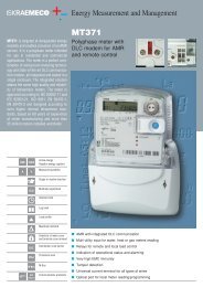
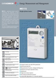
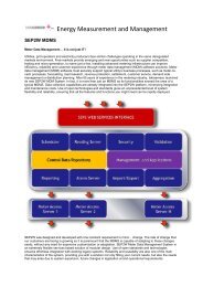
<strong>ME162</strong> ─ Electronic single-phase kWh-meter<br />
1. Meter appearance<br />
6<br />
5 4 3<br />
2<br />
1<br />
7<br />
1 2 3<br />
1. Current terminals - phase 3. Auxiliary terminals<br />
2. Current terminals - neutral<br />
Fig. 2: Terminal block in compliance<br />
with the DIN 43857 standard<br />
8<br />
Fig. 1: Meter parts<br />
1. Meter base 5. LED - pulse emitting<br />
2. Meter cover 6. Optical port<br />
3. Scroll push-button 7. Terminal block cover<br />
4. LCD 8. Fixing screw of<br />
terminal block cover<br />
A screw for fixing the terminal block cover (item 8) is<br />
sealed with a seal of electric utility.<br />
1.1. Meter case<br />
A compact meter case consists of a meter base (item<br />
1) with a terminal block and two fixing elements for<br />
mounting the meter, a meter cover (item 2) and a<br />
terminal block cover (item 7). The meter case is made<br />
of self-extinguishing UV stabilized polycarbonate<br />
which can be recycled. The meter case ensures<br />
double insulation and IP53 (IEC 60529) protection<br />
level against dust and water penetration.<br />
The meter cover is made of polycarbonate. It is permanently<br />
stuck to the meter base so that access to<br />
the meter interior is not possible. Meter data are<br />
engraved in the meter cover.<br />
A nickel-plated iron ring is positioned in the left top<br />
corner and is used for attaching an optical probe to<br />
the optical port (item 6). A push-button for data<br />
scrolling is in the right top angle (item 3).<br />
1.2. Terminal block<br />
The terminal block complies with the DIN 43857 or<br />
the BS 5685 standard. It accommodates current<br />
terminals and optional auxiliary terminals. There is no<br />
potential link as the metering element is based on a<br />
shunt. Therefore during the meters testing they<br />
should be connected via an isolation transformer.<br />
1 2<br />
1. Current terminals - mains 3. Auxiliary terminals<br />
2. Current terminals – load<br />
Fig. 3: Terminal block in compliance<br />
with the BS 5685 standard<br />
Current terminals (items 1 and 2) are made of solid<br />
brass. At the DIN terminal block version the bore<br />
diameter is 8.5 mm and enables connection of conductors<br />
with cross sections up to 25 mm 2 . At the BS<br />
terminal block version the bore diameter is 9.5 mm<br />
and enables connection of conductors with cross<br />
sections up to 35 mm 2 . The conductors are fixed with<br />
two screws. The recommended torque for fixing the<br />
conductors is 2.5 Nm.<br />
Up to six auxiliary terminals (item 3) for optional<br />
inputs and outputs can be built into the meter on<br />
request. The bore diameter of the auxiliary terminals<br />
is 3.5 mm. Wires are fixed with a screw. In addition,<br />
two auxiliary voltage terminals for power supply of an<br />
external device can be built-in on request too.<br />
Both current and auxiliary terminals are nickel-plated<br />
at a tropical meter version.<br />
The terminal cover can be long or short and is fixed<br />
with a sealing screw. A meter connection diagram is<br />
stuck on the inner side of the terminal cover.<br />
3<br />
4 of 14