ME162 - Technical Description - Iskraemeco UK
ME162 - Technical Description - Iskraemeco UK
ME162 - Technical Description - Iskraemeco UK

You also want an ePaper? Increase the reach of your titles
YUMPU automatically turns print PDFs into web optimized ePapers that Google loves.
Energy Measurement and Management<br />
<strong>ME162</strong><br />
Single-Phase Electronic Meter<br />
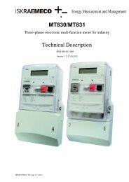
<strong>Technical</strong> <strong>Description</strong><br />
Version 1.1, 02.06. 2006<br />
Index:<br />
<strong>ME162</strong> – Electronic single-phase time-of-use<br />
kWh-meter ................................................................ 3<br />
1. Meter appearance ................................................ 4<br />
1.1. Meter case ...................................................... 4<br />
1.2. Terminal block................................................. 4<br />
1.3. Meter over-all dimensions............................... 5<br />
2. Meter configuration ............................................. 5<br />
2.1. Metering elements .......................................... 5<br />
2.2. Power supply stage......................................... 5<br />
2.3. Microcontroller ................................................ 5<br />
2.3.1. Billing results keeping .............................. 6<br />
2.4. Real-time clock ............................................... 6<br />
2.4.1. RTC back-up power supply...................... 6<br />
2.4.2. Testing RTC accuracy.............................. 6<br />
2.4.3. Time-of-use registration ........................... 6<br />
2.5. LCD................................................................. 6<br />
2.5.1. LCD testing............................................... 7<br />
2.5.2. Data display.............................................. 7<br />
2.5.3. Signal flags............................................... 7<br />
2.6. Communication channel(s) ............................. 7<br />
2.6.1. Optical port ............................................... 7<br />
2.6.2. CS interface.............................................. 8<br />
2.6.3. Data downloaded via communication<br />
channel(s) ...........................................................8<br />
2.6.4. Error register description ..........................9<br />
2.6.5. Communication protocol...........................9<br />
2.7. LED..................................................................9<br />
2.8. Data scroll push-button ...................................9<br />
2.9. Tariff Inputs......................................................9<br />
2.10. Outputs ........................................................10<br />
2.10.1. Pulse outputs ........................................10<br />
2.10.2. Tariff outputs.........................................10<br />
3. Antifraud protection...........................................10<br />
3.1. Meter seal......................................................10<br />
3.2. Always positive registration ...........................10<br />
3.3. Password.......................................................10<br />
3.4. Reverse energy flow indicator.......................10<br />
4. Handling with the meter ....................................10<br />
5. Meter maintenance.............................................10<br />
6. Meter connection ...............................................10<br />
7. Meter connection diagrams ..............................11<br />
8. <strong>Technical</strong> data ....................................................12<br />
9. Meter type designation......................................12
Energy Measurement and Management
<strong>ME162</strong> ─ Electronic single-phase kWh-meter<br />
<strong>ME162</strong> – Electronic single-phase<br />
time-of-use kWh-meter<br />
The <strong>ME162</strong> electronic single-phase meters are<br />
designed for measurement and registration of<br />
active energy in single-phase two-wire networks<br />
for direct connection. The metering and technical<br />
properties of the meters comply with the EN<br />
50470-1 and -3 European standards classes A and<br />
B as well as with the IEC 62053-21 and IEC 62052-<br />
11 (former IEC 61036) international standards for<br />
electronic meters of active energy for classes 2<br />
and 1.<br />
A built-in time switch complies with the IEC<br />
62054-21 and IEC 62052-21 standards. It enables<br />
energy registration in up to four tariffs.<br />
The meters are designed and manufactured in<br />
compliance with the ISO 9001 standard.<br />
<strong>ME162</strong> meter properties:<br />
• Meter of active energy<br />
• Accuracy class 1 or 2<br />
• Accuracy class A or B by EN 50470-1<br />
• Modes of energy measurement and<br />
registration<br />
• For one-way energy flow direction (import),<br />
with an electronic reverse running stop<br />
• For two energy flow directions (import, export)<br />
• For one-way energy flow direction, with always<br />
positive registration, i.e. energy flowing<br />
in the export direction is registered as it flows<br />
in import direction too<br />
• Meter quality:<br />
• Due to high accuracy and long term stability<br />
of the metering elements no meter recalibration<br />
over its life-time is required<br />
• Long meter life-time and high meter reliability<br />
• High immunity to EMC<br />
• Time-of-use registration (up to 4 tariffs):<br />
• Tariffs change-over by internal real-time clock<br />
• Optional tariff inputs<br />
• Communication channel:<br />
• Infrared optical port in compliance with the<br />
IEC 62056-21 for local meter programming<br />
and data down-loading<br />
• CS interface (20-mA current loop - option)<br />
• IEC 62056 – 21, mode C protocol<br />
• LCD:<br />
• 7-segment, with 8 characters and 7 signal<br />
flags<br />
• Optional no-power data display<br />
• Data display modes:<br />
• Automatic cyclic data display with display<br />
time of 8 sec (adjustable)<br />
• Manual data display mode (by pressing the<br />
Scroll push-button)<br />
• Indicators:<br />
• LCD:<br />
- Valid tariff at the moment<br />
- Meter status and alarms<br />
- Energy flow direction<br />
• LED:<br />
- Imp / kWh<br />
• Pulse output:<br />
• Class A by IEC 62053-31 (option)<br />
• Optomos relay with make contact (option)<br />
• Plastic meter case:<br />
• Made of high quality self-distinguishing UV<br />
stabilized material that can be recycled<br />
• Double insulation<br />
• IP53 protection against dust and water<br />
penetration (by IEC 60529)<br />
3 of 14
<strong>ME162</strong> ─ Electronic single-phase kWh-meter<br />
1. Meter appearance<br />
6<br />
5 4 3<br />
2<br />
1<br />
7<br />
1 2 3<br />
1. Current terminals - phase 3. Auxiliary terminals<br />
2. Current terminals - neutral<br />
Fig. 2: Terminal block in compliance<br />
with the DIN 43857 standard<br />
8<br />
Fig. 1: Meter parts<br />
1. Meter base 5. LED - pulse emitting<br />
2. Meter cover 6. Optical port<br />
3. Scroll push-button 7. Terminal block cover<br />
4. LCD 8. Fixing screw of<br />
terminal block cover<br />
A screw for fixing the terminal block cover (item 8) is<br />
sealed with a seal of electric utility.<br />
1.1. Meter case<br />
A compact meter case consists of a meter base (item<br />
1) with a terminal block and two fixing elements for<br />
mounting the meter, a meter cover (item 2) and a<br />
terminal block cover (item 7). The meter case is made<br />
of self-extinguishing UV stabilized polycarbonate<br />
which can be recycled. The meter case ensures<br />
double insulation and IP53 (IEC 60529) protection<br />
level against dust and water penetration.<br />
The meter cover is made of polycarbonate. It is permanently<br />
stuck to the meter base so that access to<br />
the meter interior is not possible. Meter data are<br />
engraved in the meter cover.<br />
A nickel-plated iron ring is positioned in the left top<br />
corner and is used for attaching an optical probe to<br />
the optical port (item 6). A push-button for data<br />
scrolling is in the right top angle (item 3).<br />
1.2. Terminal block<br />
The terminal block complies with the DIN 43857 or<br />
the BS 5685 standard. It accommodates current<br />
terminals and optional auxiliary terminals. There is no<br />
potential link as the metering element is based on a<br />
shunt. Therefore during the meters testing they<br />
should be connected via an isolation transformer.<br />
1 2<br />
1. Current terminals - mains 3. Auxiliary terminals<br />
2. Current terminals – load<br />
Fig. 3: Terminal block in compliance<br />
with the BS 5685 standard<br />
Current terminals (items 1 and 2) are made of solid<br />
brass. At the DIN terminal block version the bore<br />
diameter is 8.5 mm and enables connection of conductors<br />
with cross sections up to 25 mm 2 . At the BS<br />
terminal block version the bore diameter is 9.5 mm<br />
and enables connection of conductors with cross<br />
sections up to 35 mm 2 . The conductors are fixed with<br />
two screws. The recommended torque for fixing the<br />
conductors is 2.5 Nm.<br />
Up to six auxiliary terminals (item 3) for optional<br />
inputs and outputs can be built into the meter on<br />
request. The bore diameter of the auxiliary terminals<br />
is 3.5 mm. Wires are fixed with a screw. In addition,<br />
two auxiliary voltage terminals for power supply of an<br />
external device can be built-in on request too.<br />
Both current and auxiliary terminals are nickel-plated<br />
at a tropical meter version.<br />
The terminal cover can be long or short and is fixed<br />
with a sealing screw. A meter connection diagram is<br />
stuck on the inner side of the terminal cover.<br />
3<br />
4 of 14
<strong>ME162</strong> ─ Electronic single-phase kWh-meter<br />
1.3. Meter over-all dimensions<br />
Meter fixing dimensions comply with the DIN 43857<br />
and the BS5695 standards.<br />
1. Measuring element<br />
2. Meter power supply unit<br />
3. Microprocessor with EEPROM<br />
4. RTC with a Li-battery<br />
5. LCD<br />
6. Impulse LED<br />
7. Scroll key<br />
8. IR optical port<br />
9. CS interface (option)<br />
10. Pulse or tariff output (option)<br />
11. Tariff input (option)<br />
2.1. Metering elements<br />
The metering element enables precise measurement<br />
of active energy in a wide metering and a temperature<br />
range.<br />
Fig. 4 – Meter with a long terminal cover<br />
The metering element consists of a current and a<br />
voltage sensor. The current sensor is a shunt, while<br />
the voltage sensor is a resistive voltage divider.<br />
Signals of currents and voltages are fed to the A/D<br />
converters. They are digitally multiplied so that instanttaneous<br />
power is calculated. The instantaneous<br />
power is integrated in a microcontroller, where it is<br />
further processed.<br />
Fig. 5 – Meter with a short terminal cover<br />
2. Meter configuration<br />
Fig. 7: Metering element<br />
The metering element ensures excellent metering<br />
properties:<br />
1. Negligible effect of electromagnetic disturbances<br />
and influence quantities<br />
2. High long-term stability so that meter re-calibration<br />
is not required over its lifetime<br />
3. Long meter lifetime and high reliability in use<br />
2.2. Power supply stage<br />
The power supply stage is a capacitor type, which<br />
enables a meter to operate accurately in a voltage<br />
range from 80% to 120% of the rated voltage.<br />
Fig. 6: Meter block-diagram<br />
The meter consists of:<br />
2.3. Microcontroller<br />
The microcontroller acquires signals from the metering<br />
elements, processes them and calculates values<br />
of measured energy. The results are stored in energy<br />
registers for particular tariffs and stores energy data<br />
5 of 14
<strong>ME162</strong> ─ Electronic single-phase kWh-meter<br />
in previous billing periods. The microcontroller also<br />
generates pulses for the LED and pulse output,<br />
drives the LCD and enables two-way communication<br />
via the optical port and CS interface (if it is built-in).<br />
All measured data are stored in a non-volatile<br />
memory (EEPROM) and are kept for more than 10<br />
years period without external power supply.<br />
2.3.1. Billing results keeping<br />
The meter keeps billing results (energy values registered<br />
by tariffs and total) for up to last 8 billing periods<br />
(months). A number of billing periods (months) for<br />
which billing results are kept is set in the factory and<br />
can not be changed subsequently. The billing results<br />
are stored in a FIFO memory, so that they are always<br />
available for the last n (n = 1, 2, …8) billing periods<br />
(months), regardless if the meter billing reset was<br />
performed by means of the RTC, via the optical port or<br />
remotely via CS interface. The metering results of the<br />
past billing periods (months) can not be displayed but<br />
can be down-loaded via the optical port or remotely by<br />
means of CS interface (20.mA current loop).<br />
The billing reset can be set to be executed by the<br />
RTC:<br />
• Once a year on a specified date and time<br />
• Every month on specified day in a month and<br />
time<br />
• Every month on a specified day in a week after<br />
specified day in a month and specified time<br />
• Every week on a specified day in a week and<br />
time<br />
• Every day<br />
2.4. Real-time clock<br />
A real-time clock is controlled with a 32.768 kHz<br />
quartz crystal which is digitally trimmed. Its accuracy<br />
is better than requested by the IEC 62054-21<br />
standard for time switches. The RTC involves an<br />
internal calendar that assures information on year,<br />
month, day, day in a week, hour, minute, second and<br />
leap year.<br />
The RTC enables:<br />
• Time-of-use registration,<br />
• Automatic meter billing reset at the end of the<br />
billing period (month)<br />
• Automatic change-over to day-light saving<br />
period and back (winter – summer time).<br />
2.4.1. RTC back-up power supply<br />
An Li-battery is used as the RTC back-up power<br />
supply. It assures 5 years of the RTC operation reserve<br />
and has 15-year lifetime. The lithium battery is<br />
positioned on the meter printed circuit board under<br />
the meter cover.<br />
On request the Li-battery also supports data display<br />
on LCD in a meter no-power state.<br />
2.4.2. Testing RTC accuracy<br />
The RTC accuracy can be tested via the imp/kWh<br />
LED (Fig. 1, item 5) when the meter is in the RTC test<br />
mode. The meter is set in the RTC test mode via the<br />
optical port by means of the <strong>Iskraemeco</strong> Meter-View<br />
software so that a command Clock control is sent to<br />
the meter. When the meter is in the RTC test mode,<br />
the RTC 4096 Hz test frequency is fed to the<br />
imp/kWh LED. The meter will stay in the RTC test<br />
mode approximately 18 hours. Then it will return back<br />
into the meter mode automatically. Other ways to exit<br />
from the RTC test mode are:<br />
• By sending a command to exit RTC test<br />
mode by means of the MeterView software<br />
• By disconnecting a meter from the voltage<br />
supply<br />
2.4.3. Time-of-use registration<br />
The meter is designed as a multi-tariff with maximum<br />
four tariffs. A tariff change-over time is defined with<br />
hour and minute. Minimal time period between<br />
change-over is five minute. The real-time clock enables<br />
complex daily and weekly tariff structures, as well<br />
as a couple of seasons in a year:<br />
• Up to 8 seasons in a year (i.e. 8 weekly tariff<br />
programs)<br />
• Up to 8 daily definitions of the tariff change-over<br />
program<br />
• Up to 10 tariff change-over inside individual daily<br />
tariff programs<br />
• Up to 30 holidays (including those based on a<br />
lunar calendar) in which a special tariff program<br />
is defined<br />
2.5. LCD<br />
The 7-segment LCD has 7 + 1 characters, 8 signal<br />
flags and an energy flow-direction indicator. Large<br />
characters and a wide angle of view, as well as<br />
optional LCD back-light, enable easy data reading.<br />
Fig.8: LCD<br />
The data characters are 8 mm high. For data identification<br />
one character is employed, it is 6 mm high.<br />
Bellow the data characters there are 8 signal flags<br />
that indicate current tariff and different meter status<br />
and alarms. The meaning of signal flags are engraved<br />
on the meter name plate below them.<br />
An indicator of energy flow direction is displayed in<br />
the right bottom corner.<br />
6 of 14
<strong>ME162</strong> ─ Electronic single-phase kWh-meter<br />
2.5.1. LCD testing<br />
The LCD can be tested automatically so that all LCD<br />
segments are displayed (Fig. 8) for 2 seconds to<br />
check if they are in order. The LCD test can be<br />
performed either:<br />
• After voltage is applied to the meter<br />
• In Auto scroll sequence or<br />
• In Manual scroll sequence<br />
2.5.2. Data display<br />
Data defined in Auto scroll sequence and in Manual<br />
scroll sequence are displayed on the LCD. Data from<br />
Auto scroll sequence are displayed in a circle, and<br />
each data is displayed for 8 sec. On request, longer<br />
data display time can be set via the meter optical port<br />
by means of <strong>Iskraemeco</strong> MeterView software. At<br />
Manual scroll sequence the blue push-button should<br />
be pressed for displaying the next piece of data. Data<br />
in Manual scroll sequence remains displayed until the<br />
push-button is pressed again or until time for<br />
automatic return into the Auto scroll sequence is<br />
elapsed.<br />
Data that can be displayed at different meter configurations<br />
are listed in the table bellow. Which of them<br />
will be displayed depends on a customer request at<br />
meter ordering.<br />
DATA ID<br />
CODE<br />
ON LCD<br />
DATA DESCRIPTION<br />
Total positive active energy (A+)<br />
0<br />
Total absolute active energy |A|<br />
Positive active energy in first tariff (T1)<br />
1<br />
Absolute active energy in first tariff |T1|<br />
Positive active energy in second tariff (T2)<br />
2<br />
Absolute active energy in second tariff |T2|<br />
Positive active energy in third tariff (T3)<br />
3<br />
Absolute active energy in third tariff |T3|<br />
Positive active energy in fourth tariff (T4)<br />
4 Absolute active energy in fourth tariff |T4|<br />
Energy registered in a single-wire mode<br />
5 Total negative active energy (A-)<br />
6 Negative active energy in first tariff (T1)<br />
7 Negative active energy in second tariff (T2)<br />
8 Negative active energy in third tariff (T3)<br />
9 Negative active energy in fourth tariff (T4)<br />
t Time hh:mm:ss<br />
d Date YY-MM-DD<br />
F Fatal error<br />
Optionally, data can be displayed on the LCD in a nopower<br />
meter state by pressing the Data scroll pushbutton.<br />
Energy data can be displayed in data formats given in<br />
a table bellow.<br />
Data format No. of integers No. of decimals<br />
6.0 6 0<br />
7.1 6 1<br />
7.0 7 0<br />
By pressing the pushbutton on the meter front side it<br />
is possible to enter into the meter test mode in which<br />
energy data are displayed with higher resolution, i.e.<br />
in data format 7.3 (i.e. 4 integers + 3 decimals). At<br />
the same time imp/kWh LED starts to emit pulses<br />
with pulse rate 200,000 imp/kWh. In this way, time<br />
needed for meter accuracy testing at low load is<br />
shortened.<br />
2.5.3. Signal flags<br />
The signal flags in the display bottom row indicate<br />
certain meter status and alarms.<br />
The signal flags from left to right have the following<br />
functions:<br />
No. FLAG STATUS MEANING<br />
1 T1 Lit Active first tariff<br />
2 T2 Lit Active second tariff<br />
3 T3 Lit Active third tariff<br />
4 T4 Lit Active fourth tariff<br />
5 Not used<br />
6 PD Lit<br />
Data display on LCD in<br />
a no-power meter state<br />
7 FF Lit Meter fatal error<br />
8 DRO Lit<br />
Meter data downloading<br />
is in progress<br />
← Lit Import energy (+A)<br />
→<br />
Lit<br />
Export energy (-A) or<br />
reversed energy flow<br />
* If the FF signal flag is displayed, the meter<br />
should be dismounted from a place of measurement<br />
and sent to an authorized repair shop or<br />
to the manufacturer for examination.<br />
2.6. Communication channel(s)<br />
The meters are equipped with an optical port for local<br />
meter programming and data downloading. Optionally<br />
they can be also equipped with a CS serial interface<br />
for remote meter programming and data downloading<br />
2.6.1. Optical port<br />
The optical port complies with the IEC 62056-21 and<br />
is used for local meter programming and data downloading.<br />
It is located in the right top corner of the<br />
meter. The communication protocol complies with<br />
IEC 62056-21, mode C. The communication is serial<br />
asynchronous with data transmission rate from 300<br />
bit/sec to 19,200 bit/sec. If data transmission rate of<br />
the used optical probe is lower than 19,200 bit/sec,<br />
the maximum permissible data transmission rate is<br />
equal to that value. If higher data transmission rate is<br />
7 of 14
<strong>ME162</strong> ─ Electronic single-phase kWh-meter<br />
set, communication via optical port will not be possible.<br />
The optical port wavelength is 660 nm and luminous<br />
intensity is min. 1 mW/sr for the ON state.<br />
2.6.2. CS interface<br />
On request the meters are equipped with a CS<br />
interface (20 mA current loop) in compliance with the<br />
DIN 66348 standard. It is used for remote data downloading<br />
and the meter programming. If a CS interface<br />
is built into the meter, than only one pulse output or<br />
one tariff input (or output) can be built in besides it.<br />
The communication has master-slave architecture,<br />
where the <strong>ME162</strong> meters are slaves and a communicator<br />
(e.g. <strong>Iskraemeco</strong> P2CA) is a master. A number<br />
of meters built-in a CS loop depends on their distance<br />
from a communicator. Up to 6 meters can be built into<br />
a CS loop if they are not far away from the<br />
communicator. If a communicator is 1,200 meters<br />
away from the meters, maximum 4 meters can be<br />
built into the CS loop.<br />
The communication protocol complies with IEC<br />
62056-21, mode C. Data transmission rate is 2,400<br />
Baud.<br />
2.6.3. Data downloaded via communication<br />
channel(s)<br />
Data downloaded via communication channels, i.e.<br />
via optical port and CS interface (if it is built into the<br />
meter are identified with EDIS codes. Besides data<br />
for a current billing period, historical data for previous<br />
billing periods can also be down-loaded via the communication<br />
channels on request. Historical data can<br />
be down-loaded for the maximum 8 last billing<br />
periods. The following data can be down-loaded via<br />
the communication channels.<br />
EDIS<br />
CODE<br />
DATA DESCRIPTION<br />
F.F. Meter fatal error<br />
0.0.0 Device address<br />
C.1.0 Meter serial number<br />
0.9.1 Time ( data format: hh:mm:ss)<br />
0.9.2 Date (data format: YY.MM.DD)<br />
1.8.0 Total positive active energy (A+)<br />
1.8.1 Positive active energy in first tariff (T1)<br />
1.8.2 Positive active energy in second tariff (T2)<br />
1.8.3 Positive active energy in third tariff (T3)<br />
1.8.4 Positive active energy in fourth tariff (T4)<br />
2.8.0 Total negative active energy (A-)<br />
2.8.1 Negative active energy in first tariff (T1)<br />
2.8.2 Negative active energy in second tariff (T2)<br />
2.8.3 Negative active energy in third tariff (T3)<br />
2.8.4 Negative active energy in fourth tariff (T4)<br />
15.8.0 Total absolute active energy |A|<br />
15.8.1 Absolute active energy in first tariff |T1|<br />
15.8.2 Absolute active energy in second tariff |T2|<br />
15.8.3 Absolute active energy in third tariff |T3|<br />
15.8.4 Absolute active energy in fourth tariff |T4|<br />
0.1.2*xx Meter billing reset time stamp of past months<br />
1.8.0*xx Total positive act. energy (A+) previous value<br />
1.8.1*xx Positive act. ener. in tariff T1 previous value<br />
1.8.2*xx Posit. act. energy in tariff T2 previous value<br />
1.8.3*xx Posit. act. energy in tariff T3 previous value<br />
1.8.4*xx Posit. act. energy in tariff T4 previous value<br />
2.8.0*xx Total negative act. ener. (A-) previous value<br />
2.8.1*xx Negat. act. energy in tariff T1 previous value<br />
2.8.2*xx Negat. act. energ. in tariff T2 previous value<br />
2.8.3*xx Negat. act. energ. in tariff T3 previous value<br />
2.8.4*xx Negat. act. energ. in tariff T4 previous value<br />
15.8.0*xx Total absolute active ener. |A| prev. value<br />
15.8.1*xx Abs. active energy in tar. T1 previous value<br />
15.8.2*xx Abs. active energy in tar. T2 previous value<br />
15.8.3*xx Abs. active energy in tar.T3 previous value<br />
15.8.4*xx Abs. active energy in tar. T4 previous value<br />
0.1.2*xx Previous value time stamp<br />
xx = 01, 02, … 08 index of previous billing periods<br />
(months)<br />
8 of 14
<strong>ME162</strong> ─ Electronic single-phase kWh-meter<br />
2.6.4. Error register description<br />
The error register F.F is a hexadecimal value and<br />
generates the following alarms when particular bits<br />
are set to 1.<br />
Bit<br />
Error description<br />
0 Check sum error in energy registers in<br />
EEPROM<br />
1 Check sum error of meter parameters in<br />
EEPROM<br />
2 Check sum error of meter parameters in RAM<br />
3 Check sum error of program code<br />
4 False tariff table<br />
5 Not implemented<br />
6 Not implemented<br />
7 Not implemented<br />
2.6.5. Communication protocol<br />
The communication protocol is IEC 62056-21 (former<br />
IEC 61107), mode C. The communication is asynchronous<br />
half-duplex.<br />
Data format:<br />
1 start bit, 7 data bits, 1 parity bit, 1 stop bit<br />
The entire data block is protected by a control mark in<br />
compliance with the DIN 66219 standard.<br />
After receiving the calling telegram at a 300 baud<br />
data transmission rate,<br />
/ ? Device address ! CR LF or / ? ! CR LF<br />
the meter reveals its identification at a 300 baud data<br />
transmission rate:<br />
/ I S K 5 M E 162 – “Program version”<br />
The meter address refers to the contents of the 0.0.0<br />
or 0.0.1 registers. Then the meter waits for 2 sec. so<br />
that the proposed data transmission rate is confirmed:<br />
ACK 0 5 0 CR LF.<br />
If the proposed baud rate is confirmed, communication<br />
at a 9,600 baud rate follows; if it is not confirmed,<br />
communication at 300 baud continues. The<br />
meter transmits the data telegram:<br />
where<br />
2.7. LED<br />
STX Data ! CR LF ETX BCC<br />
STX: stands for the start of a text;<br />
Data: refers to codes and data<br />
! CR LF: stands for the end of data<br />
ETX: stands for the end of a text<br />
BCC: stands for Block Check Character –<br />
parity check<br />
The meter is provided with a LED on the front plate.<br />
The imp/kWh LED has two functions depending on<br />
the meter mode. In the meter mode it is used for<br />
testing the meter accuracy and blinks with a pulse<br />
rate 1,000 imp/kWh, the pluses width is 40 ms.<br />
LED STATUS INDICATION<br />
Imp/kWh<br />
Blinks<br />
Lit<br />
OFF<br />
Energy is registered. The<br />
pulse rate is proportional to<br />
demand<br />
Voltage applied to the meter,<br />
but load current is lower than<br />
the meter starting current.<br />
No voltage is applied to the<br />
meter.<br />
In the RTC testing mode it is used for testing the RTC<br />
accuracy and blinks with 4096 Hz test frequency (see<br />
item 2.4.2 Testing RTC accuracy).<br />
2.8. Data scroll push-button<br />
There is a Scroll push-button on the meter front side.<br />
Its primary function is to scroll data from the Manual<br />
scroll sequence on the LCD. It should be pressed<br />
again and again for each next data to be displayed.<br />
It also enables data displaying on the LCD when the<br />
meter is in no-power state if such a function was<br />
requested at meter ordering. If no voltage is applied<br />
to the meter and the Scroll pushbutton is pressed, the<br />
first data from the Manual scroll sequence appears<br />
on the LCD and, at the same time, the PD signal flag<br />
is displayed indicating that the meter is in a no-power<br />
state. The LCD remains turned-on for a period of<br />
Manual sequence time-out (i.e. 60 sec.) if the Scroll<br />
pushbutton is not pressed again. After that time the<br />
LCD turns off automatically.<br />
2.9. Tariff Inputs<br />
Optionally the meter can be equipped with one (tworate<br />
meters) or two (3- and 4-rate meters) tariff inputs<br />
that are used for external tariff changeover. If a CS<br />
interface is built into the meter, than only one tariff<br />
input can be built in besides it.<br />
The tariff input control voltage is a phase voltage. The<br />
tariff input is set into logic 1 state if voltage applied to<br />
the tariff input is Ut > 0.8Ur, and is set into logic 0<br />
state if voltage applied to the tariff input is Ut < 0.2Ur.<br />
A combination of voltages applied to the tariff inputs<br />
determines which tariff is valid, e.g.:<br />
Tariff input 13 Tariff input 33 Valid tariff<br />
0 0 T1<br />
1 0 T2<br />
0 1 T3<br />
1 1 T4<br />
On request, a ground of the tariff inputs can be<br />
connected internally to the meter ground.<br />
9 of 14
<strong>ME162</strong> ─ Electronic single-phase kWh-meter<br />
2.10. Outputs<br />
The <strong>ME162</strong> meters can be equipped either with pulse<br />
or tariff outputs. If a CS interface is built into the<br />
meter, than only one pulse or tariff output can be built<br />
in besides it.<br />
2.10.1. Pulse outputs<br />
Optionally the meter can be equipped with one or two<br />
pulse outputs. Two pulse outputs are built-in only at<br />
two energy flow-directions (an output for each energy<br />
flow direction).<br />
The pulse output can be either an IEC 62053-31<br />
class A, (S0 by DIN 43864) or an opto-MOS relay type.<br />
The pulse transmission distance is 0,5 and 1,000 m<br />
respectively. The optomos relay has a make contact<br />
with switching capability 25 VA (100 mA at 250 V).<br />
2.10.2. Tariff outputs<br />
Optionally the meter can be equipped with one or two<br />
tariff outputs. The tariff output is an optomos relay with<br />
a make contact with switching capability 25 VA (100<br />
mA at 250 V).<br />
3. Antifraud protection<br />
Special attention is paid to a system of meter data<br />
protection in order to prevent meter tampering by use<br />
of hardware and software counter measures as well<br />
as a meter design itself.<br />
3.1. Meter seal<br />
The meter cover is permanently stuck to the meter<br />
base thus preventing access to the meter interior.<br />
The terminal block cover is fixed with a screw and is<br />
secured with a wire and a led or plastic seal.<br />
3.2. Always positive registration<br />
The option of always positive energy registration<br />
regardless in which direction energy flows through<br />
the metering element prevents meter misuse by<br />
wrong connection of the conductors into the terminal<br />
block. In addition, a reverse energy flow direction<br />
arrow is displayed when energy flows in reversed<br />
direction.<br />
3.3. Password<br />
A password is implemented for protection of meter<br />
parameters setting that influence in the meter<br />
measuring.<br />
3.4. Reverse energy flow indicator<br />
Meters designed for energy measurement in one<br />
energy flow direction have a reverse energy flow<br />
indicator. In case that energy flows in opposite direction<br />
through the meter, the arrow for export energy<br />
flow (-A) is displayed in the LCD and at the same<br />
time the kWh LED is lit.<br />
4. Handling with the meter<br />
Two sets of tools are available:<br />
• For service programming and readout:<br />
• MeterView (<strong>Iskraemeco</strong> software)<br />
• An optical probe<br />
• PC: a desk-top, a laptop<br />
The tool is intended for the operators who service or<br />
reprogram the meters in the laboratory or in the field.<br />
• For billing readout and programming:<br />
• MeterRead (<strong>Iskraemeco</strong> software) for all types of<br />
Palm-top PCs operating in the Windows CE<br />
environment<br />
• An optical probe<br />
The tool is intended for meter readers in the field.<br />
5. Meter maintenance<br />
The meter is designed and manufactured in such a<br />
way that no maintenance is required in the entire<br />
meter lifetime. Measuring stability assures that no<br />
recalibration is required. If a battery is built into the<br />
meter, its capacity is sufficient to backup all functions<br />
for the entire meter lifetime.<br />
6. Meter connection<br />
When the terminal cover is removed a user can be<br />
exposed to voltage that can cause injuries or death.<br />
Therefore only a qualified personal is allowed to install<br />
the meters.<br />
The meter installation procedure is as follows:<br />
1. Check if network voltage corresponds with the<br />
meter rated voltage printed on the meter name<br />
plate and current to be measured is lower than the<br />
meter maximum current Imax.<br />
2. Place the meter to a metering place and fix it with<br />
two screws.<br />
3. Connect the meter to network in compliance with<br />
the meter connection diagram that is stuck on the<br />
inner side of the terminal cover. Tight the terminal<br />
screws with recommended 2.5 Nm torque.<br />
4. Check connection indication:<br />
• LED is lit (voltage applied, load current is less<br />
than starting current)<br />
• LED is blinking (with frequency proportional to<br />
load current)<br />
5. Check time and date set in the meter and, if<br />
necessary, enter correct values.<br />
6. If automatic billing reset is implemented, perform<br />
meter billing reset and seal the Reset pushbutton.<br />
7. Place the terminal cover in its position and fix it<br />
with a screw. Seal the terminal cover screw.<br />
10 of 14
<strong>ME162</strong> ─ Electronic single-phase kWh-meter<br />
7. Meter connection diagrams<br />
The meter connection diagrams in compliance with<br />
BS 5685 and DIN 43857 standards respectively are<br />
shown in the figure 9.<br />
Fig. 9 – Meter connection diagrams<br />
11 of 14
<strong>ME162</strong> ─ Electronic single-phase kWh-meter<br />
8. <strong>Technical</strong> data<br />
Accuracy class<br />
by IEC 62053-21<br />
by EN 50470-1<br />
Basic current Ib<br />
Max. current Imax<br />
Thermal current<br />
Min. current<br />
Staring current<br />
Rated voltage Un<br />
Voltage range<br />
Rated frequency<br />
Meter constant<br />
Clock accuracy (25°C)<br />
2 or 1<br />
A or B<br />
5, 10, 20 A<br />
85 A (at DIN meters)<br />
100 A (at BS meters)<br />
1.2 Imax<br />
0.05 Ib<br />
0.004 Ib<br />
120, 220, 230, 240 V<br />
0.8 Un ... 1.15 Un<br />
50 Hz, 60 Hz<br />
1,000 imp/kWh<br />
≤6 ppm i.e.<br />
≤±3 min / year<br />
RTC control<br />
Quartz crystal 32 kHz<br />
Temperature range of<br />
-25°C ... +60°C<br />
operation<br />
Extended temperature<br />
- 40°C ... +70°C<br />
range of operation<br />
Storing temperature -40°C ... +85°C<br />
Current circuit burden
13 of 14<br />
<strong>ME162</strong> ─ Electronic single-phase kWh-meter
<strong>ME162</strong> ─ Electronic single-phase kWh-meter<br />
Owing to periodically improvements of our products the supplied products<br />
can differ in some details from data stated in this technical description.<br />
<strong>Iskraemeco</strong> d.d., Energy Measurement and Management<br />
4000 Kranj, Savska loka 4, Slovenia<br />
Telephone (+386 4) 206 40 00, Fax: (+386 4) 206 43 76<br />
http://www.iskraemeco.si, E-mail: info@iskraemeco.si<br />
Published: Iskraeeco, Marketing, Data subjected to alteration without notice.<br />
<strong>ME162</strong>_TD_v11_Eng.doc<br />
14 of 14