Flanged Connections for PE pipes, restraint
Flanged Connections for PE pipes, restraint
Flanged Connections for PE pipes, restraint
You also want an ePaper? Increase the reach of your titles
YUMPU automatically turns print PDFs into web optimized ePapers that Google loves.
<strong>Flanged</strong> <strong>Connections</strong> <strong>for</strong> <strong>PE</strong> <strong>pipes</strong>, <strong>restraint</strong><br />
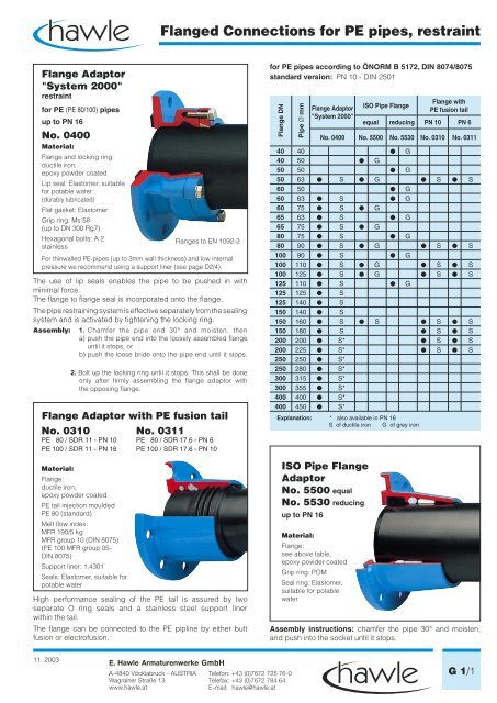
Flange Adaptor<br />
"System 2000"<br />
<strong>restraint</strong><br />
<strong>for</strong> <strong>PE</strong> (<strong>PE</strong> 80/100) <strong>pipes</strong><br />
up to PN 16<br />
No. 0400<br />
Material:<br />
Flange and locking ring:<br />
ductile iron,<br />
epoxy powder coated<br />
Lip seal: Elastomer, suitable<br />
<strong>for</strong> potable water<br />
(durably lubricated)<br />
Flat gasket: Elastomer<br />
Grip ring: Ms 58<br />
(up to DN 300 Rg7)<br />
Hexagonal bolts: A 2<br />
stainless<br />
The use of lip seals enables the pipe to be pushed in with<br />
minimal <strong>for</strong>ce.<br />
The flange to flange seal is incorporated onto the flange.<br />
The pipe restraining system is effective separately from the sealing<br />
system and is activated by tightening the locking ring.<br />
Assembly:<br />
Flanges to EN 1092-2<br />
For thinwalled <strong>PE</strong>-<strong>pipes</strong> (up to 3mm wall thickness) and low internal<br />
pressure we recommend using a support liner (see page D2/4).<br />
1. Chamfer the pipe end 30° and moisten, then<br />
a) push the pipe end into the loosely assembled flange<br />
until it stops, or<br />
b) push the loose bride onto the pipe end until it stops.<br />
2. Bolt up the locking ring until it stops. This shall be done<br />
only after firmly assembling the flange adaptor with<br />
the opposing flange.<br />
Flange Adaptor with <strong>PE</strong> fusion tail<br />
No. 0310 No. 0311<br />
<strong>PE</strong> 80 / SDR 11 - PN 10 <strong>PE</strong> 80 / SDR 17.6 - PN 6<br />
<strong>PE</strong> 100 / SDR 11 - PN 16 <strong>PE</strong> 100 / SDR 17.6 - PN 10<br />
Material:<br />
Flange:<br />
ductile iron,<br />
epoxy powder coated<br />
<strong>PE</strong> tail injection moulded<br />
<strong>PE</strong> 80 (standard)<br />
Melt flow index:<br />
MFR 190/5 kg<br />
MFR group 10 (DIN 8075)<br />
(<strong>PE</strong> 100 MFR group 05-<br />
DIN 8075)<br />
Support liner: 1.4301<br />
Seals: Elastomer, suitable <strong>for</strong><br />
potable water<br />
High per<strong>for</strong>mance sealing of the <strong>PE</strong> tail is assured by two<br />
separate O ring seals and a stainless steel support liner<br />
within the tail.<br />
The flange can be connected to the <strong>PE</strong> pipline by either butt<br />
fusion or electrofusion.<br />
<strong>for</strong> <strong>PE</strong> <strong>pipes</strong> according to ÖNORM B 5172, DIN 8074/8075<br />
standard version: PN 10 - DIN 2501<br />
Flange DN<br />
Pipe Ø mm<br />
ISO Pipe Flange<br />
Adaptor<br />
No. 5500 equal<br />
No. 5530 reducing<br />
up to PN 16<br />
Material:<br />
Flange:<br />
see above table,<br />
epoxy powder coated<br />
Grip ring: POM<br />
Flange Adaptor<br />
"System 2000"<br />
Seal ring: Elastomer,<br />
suitable <strong>for</strong> potable<br />
water<br />
ISO Pipe Flange<br />
Flange with<br />
<strong>PE</strong> fusion tail<br />
equal reducing PN 10 PN 6<br />
No. 0400 No. 5500 No. 5530 No. 0310 No. 0311<br />
40 40 G<br />
40 50 G<br />
50 50 G<br />
50 63 S G S S<br />
60 50 G<br />
60 63 S G<br />
60 75 S G<br />
65 63 S G<br />
65 75 S G<br />
80 75 S G<br />
80 90 S G S S<br />
100 90 S G<br />
100 110 S G S S<br />
100 125 S G S S<br />
125 110 S G<br />
125 125 S<br />
125 140 S<br />
150 140 S<br />
150 160 S S S S<br />
150 180 S S S<br />
200 200 S* S S<br />
200 225 S* S S<br />
250 250 S*<br />
250 280 S*<br />
300 315 S*<br />
300 355 S*<br />
400 400 S*<br />
400 450 S*<br />
Explanation: * also available in PN 16<br />
S of ductile iron G of grey iron<br />
Assembly instructions: chamfer the pipe 30° and moisten,<br />
and push into the socket until it stops.<br />
11. 2003<br />
G 1/1
<strong>Flanged</strong> <strong>Connections</strong> <strong>for</strong> <strong>PE</strong> <strong>pipes</strong>, <strong>restraint</strong><br />
No. 0400<br />
No. 0400 / No. 5500<br />
Flange<br />
DN<br />
Pipe<br />
Ø mm<br />
D<br />
K<br />
b - No. ˜ L (assembled) E - No. Bolts Weight No.<br />
0400 5500 0400 5500 0400 5500 Qty. Thread 0400 5500<br />
40 50 150 112 23 97 93 4 M 16 2,6<br />
50 63 165 125 19 23 90 94 80 80 4 M 16 3,6 3,2<br />
60 63 175 135 19 90 80 4 M 16 3,8<br />
60 75 175 138 19 24 92 105 82 100 4 M 16 4,0 3,9<br />
65 63 185 145 19 90 80 4 M 16 4,3<br />
65 75 185 145 19 24 92 105 82 99 4 M 16 4,3 4,0<br />
80 75 200 160 19 92 82 8 M 16 5,0<br />
80 90 200 160 19 24 95 101 85 96 8 M 16 5,5 4,2<br />
100 90 220 180 19 95 85 8 M 16 6,8<br />
100 110 220 180 19 25 95 124 85 119 8 M 16 6,2 6,7<br />
100 125 220 180 19 25 97 173 87 162 8 M 16 7,0 8,2<br />
125 110 250 210 19 95 85 8 M 16 7,8<br />
125 125 250 210 19 97 87 8 M 16 8,2<br />
125 140 250 210 19 103 93 8 M 16 8,5<br />
150 140 285 240 19 103 93 8 M 16 11,3<br />
150 160 285 240 19 19 115 155 105 148 8 M 20 10,5 9,3<br />
150 180 285 240 19 125 115 8 M 20 11,6<br />
200 200 340 295 20 135 125 8 M 20 18,0<br />
200 225 340 295 20 138 128 8 M 20 16,0<br />
250 250 400 350 22 155 145 12 M 20 22,0<br />
250 280 400 350 22 158 148 12 M 20 29,0<br />
300 315 455 400 25 184 174 12 M 20 44,0<br />
300 355 455 400 25 277 237 12 M 20 61,0<br />
400 400 565 515 25 242 230 16 M 24 97,0<br />
400 450 565 515 25 302 260 16 M 24 81,0<br />
No. 5530<br />
No. 0310 / No. 0311<br />
Flange<br />
DN<br />
Pipe<br />
Ø mm<br />
D K b L E Bolts<br />
Qty.<br />
Thread<br />
Weight<br />
kg<br />
40 40 150 110 21 85 80 4 M 16 2,4<br />
50 50 165 125 23 97 93 4 M 16 3,0<br />
60 50 175 135 24 97 94 4 M 16 3,4<br />
60 63 175 135 24 94 90 4 M 16 3,9<br />
65 63 185 145 24 94 90 4 M 16 4,2<br />
80 75 200 160 24 105 100 8 M 16 5,0<br />
100 90 220 180 25 101 96 8 M 16 5,9<br />
125 110 250 210 26 124 119 8 M 16 8,8<br />
No. 0310 / No. 0311<br />
Flange<br />
DN<br />
Pipe<br />
Ø mm<br />
D K b L L 1 s Bolts<br />
(PN 6)* (PN 10)* Qty. Thread<br />
Weight<br />
kg<br />
50 63 165 125 19 106 291 3,6 5,8 4 M 16 4,0<br />
80 90 200 160 20 125 305 5,1 8,2 8 M 16 6,7<br />
100 110 220 180 21 142 327 6,3 10,0 8 M 16 9,3<br />
100 125 220 180 19 190 373 7,1 11,4 8 M 16 12,4<br />
150 160 285 240 23 175 358 9,1 14,6 8 M 20 16,0<br />
150 180 285 240 19 260 437 10,2 16,4 8 M 20 23,0<br />
200 200 340 295 20 210 403 11,4 18,3 8 M 20 28,0<br />
200 225 340 295 20 210 403 12,8 20,5 8 M 20 28,0<br />
*SDR 17.6 *SDR 11<br />
G 1/2<br />
Illustrations, technical data, dimensions and weights are subject to alteration without notice. 11. 2003


