

Crown Low Power Transmitters - Crown Broadcast
Crown Low Power Transmitters - Crown Broadcast
Crown Low Power Transmitters - Crown Broadcast

You also want an ePaper? Increase the reach of your titles
YUMPU automatically turns print PDFs into web optimized ePapers that Google loves.
4.2 Audio Processor Circuit Board<br />
The audio processor board provides the audio control functions of a compressor,<br />
limiter, and expander. Illustration 6–5 and accompanying schematic may be useful<br />
to you during this discussion.<br />
Audio<br />
Processor<br />
Board<br />
FM250<br />
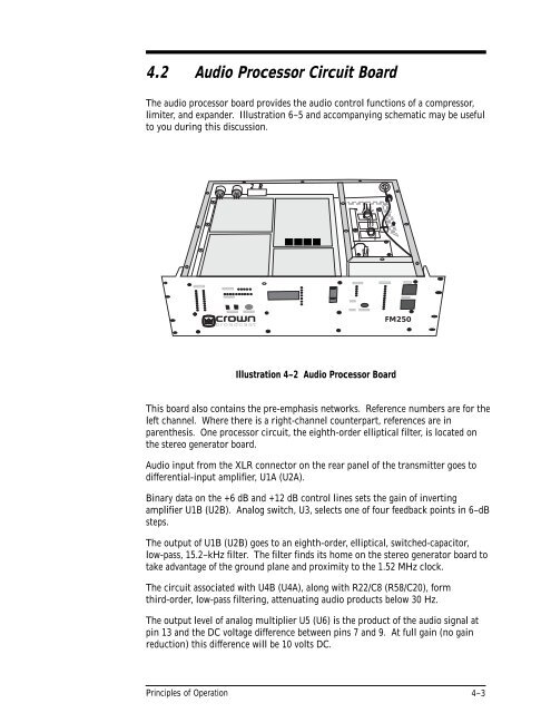
Illustration 4–2 Audio Processor Board<br />
This board also contains the pre-emphasis networks. Reference numbers are for the<br />
left channel. Where there is a right-channel counterpart, references are in<br />
parenthesis. One processor circuit, the eighth-order elliptical filter, is located on<br />
the stereo generator board.<br />
Audio input from the XLR connector on the rear panel of the transmitter goes to<br />
differential-input amplifier, U1A (U2A).<br />
Binary data on the +6 dB and +12 dB control lines sets the gain of inverting<br />
amplifier U1B (U2B). Analog switch, U3, selects one of four feedback points in 6–dB<br />
steps.<br />
The output of U1B (U2B) goes to an eighth-order, elliptical, switched-capacitor,<br />
low-pass, 15.2–kHz filter. The filter finds its home on the stereo generator board to<br />
take advantage of the ground plane and proximity to the 1.52 MHz clock.<br />
The circuit associated with U4B (U4A), along with R22/C8 (R58/C20), form<br />
third-order, low-pass filtering, attenuating audio products below 30 Hz.<br />
The output level of analog multiplier U5 (U6) is the product of the audio signal at<br />
pin 13 and the DC voltage difference between pins 7 and 9. At full gain (no gain<br />
reduction) this difference will be 10 volts DC.<br />
Principles of Operation<br />
4–3


