KFX400 Dyna FS Ignition (Programmable)
KFX400 Dyna FS Ignition (Programmable)
KFX400 Dyna FS Ignition (Programmable)

You also want an ePaper? Increase the reach of your titles
YUMPU automatically turns print PDFs into web optimized ePapers that Google loves.
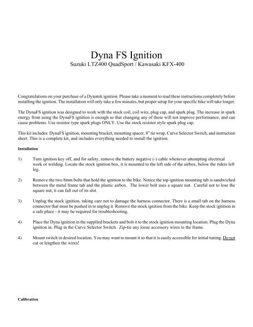
<strong>Dyna</strong> <strong>FS</strong> <strong>Ignition</strong><br />
Suzuki LTZ400 QuadSport / Kawasaki KFX-400<br />
Congratulations on your purchase of a <strong>Dyna</strong>tek ignition. Please take a moment to read these instructions completely before<br />
installing the ignition. The installation will only take a few minutes, but proper setup for your specific bike will take longer.<br />
The <strong>Dyna</strong><strong>FS</strong> ignition was designed to work with the stock coil, coil wire, plug cap, and spark plug. The increase in spark<br />
energy from using the <strong>Dyna</strong><strong>FS</strong> ignition is enough so that changing any of these will not improve performance, and can<br />
cause problems. Use resistor type spark plugs ONLY. Use the stock resistor style spark plug cap.<br />
This kit includes: <strong>Dyna</strong><strong>FS</strong> ignition, mounting bracket, mounting spacer, 8” tie wrap, Curve Selector Switch, and instruction<br />
sheet. This is a complete kit, and includes everything needed to install the ignition.<br />
Installation<br />
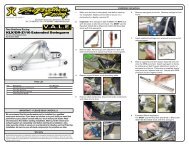
1) Turn ignition key off, and for safety, remove the battery negative (-) cable whenever attempting electrical<br />
work or welding. Locate the stock ignition box, it is mounted to the left side of the airbox, below the riders left<br />
leg.<br />
2) Remove the two 8mm bolts that hold the ignition to the bike. Notice the top ignition mounting tab is sandwiched<br />
between the metal frame tab and the plastic airbox. The lower bolt uses a square nut. Careful not to lose the<br />
square nut, it can fall out of its slot.<br />
3) Unplug the stock ignition, taking care not to damage the harness connector. There is a small tab on the harness<br />
connector that must be pushed in to unplug it. Remove the stock ignition from the bike. Keep the stock ignition in<br />
a safe place - it may be required for troubleshooting.<br />
4) Place the <strong>Dyna</strong> ignition in the supplied brackets and bolt it to the stock ignition mounting location. Plug the <strong>Dyna</strong><br />
ignition in. Plug in the Curve Selector Switch. Zip-tie any loose accessory wires to the frame.<br />
4) Mount switch in desired location. You may want to mount it so that it is easily accessible for initial tuning. Do not<br />
cut or lengthen the wires!<br />
Calibration
The <strong>Dyna</strong> <strong>FS</strong> ignition is preprogrammed with 4 timing curves. The curves are selected by the curve selector switch.<br />
Removing the switch will cause the ignition to default to the curve in position 4(labeled STOCK on the curve switch)<br />
which is the stock timing curve.<br />
Curve 4 is identical to the curve that came with the stock ignition module. Due to improved microprocessor control and<br />
significantly higher spark energy, the performance of this curve will be enhanced. A quicker throttle response and increased<br />
power over stock is still achieved with the stock ignition curve. For the other 3 timing curves, see the attached chart for the<br />
timing information.<br />
Use of this ignition may require rejetting of the carburetor to supply more fuel to maximize performance gains. If you are<br />
unsure of this tuning process, the services of a competent mechanic should be employed. Curve 4, the stock curve, is least<br />
likely to require any sort of jetting adjustment.<br />
Using the other curves may result in a lean misfire condition at high RPMs when the jetting is not properly set. Do not<br />
operate the engine in a lean condition for extended periods or damage may result.<br />
This ignition will allow the engine to rev to a higher RPM than what it has before. The rev limit is programmable from<br />
2000rpm to 12,000rpm. Stock rev limit is 9100rpm. The revlimit is pre-programmed to 10,500. Because the rev limit is<br />
increased, the performance limits of other engine parts (valvetrain for example) may be found. It may be necessary to<br />
replace these parts for best engine performance. Consult with an engine builder for answers on what works best for your<br />
engine.<br />
<strong>Programmable</strong> ignitions<br />
Lap-top/PC <strong>Programmable</strong> versions (suffixed with a P in the part number) require a separate programming kit to reprogram<br />
them. It is not supplied with the ignition. If the programmable ignition was not purchased directly from <strong>Dyna</strong>tek, the dealer<br />
may have programmed a custom set of ignition curves. The dealer should be consulted with any questions regarding the<br />
curves that are programmed into the ignition.<br />
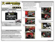
The Launch RPM is programmable and can be wired to a separate clutch switch (not included) for a “two step/low side”<br />
launch limiter. See attached wiring diagram for installation.<br />
<strong>Programmable</strong> ignitions are shipped with additional leads coming out of the ignition. These leads allow the ignition to<br />
control other features. To program these features, follow the instructions in the programming kit.<br />
PURPLE – <strong>Programmable</strong> launch limiter. Ground this wire to activate (requires separate clutch switch)<br />
GREEN – Tachometer output, for a standard 12v, two pulse per rev aftermarket tach.<br />
WHITE – Optional 2-amp switch to ground, referenced as “Power Jet” in PC Software.<br />
BLUE – Optional 2-amp switch to ground, referenced as “PV Solenoid” in PC Software.<br />
The White & Blue 2-amp switches can be used to activate a solenoid or relay. Connect the relay with hot +12v wired<br />
to one side of the relay coil, and the other side connected to White or Blue. When the rpm activates the switch, it will<br />
be grounded inside the ignition box, causing current to flow through the relay coil. DO NOT connect any device which<br />
requires more than 2 Amps (Amps=Volts/Resistance). See attached wiring diagram for wiring the relay.<br />
Troubleshooting<br />
2
Troubleshooting the <strong>Dyna</strong> ignition is simple. If the bike will not start or run at all, reinstall the stock ignition. If this fixes<br />
the problem, then the <strong>Dyna</strong> ignition should be returned to <strong>Dyna</strong>tek for testing. If this does not fix the problem, then the<br />
problem is somewhere else on the bike. Follow the troubleshooting procedures outlined in your bike shop manual.<br />
If the bike runs, but poorly, put the stock ignition back on the bike. If this fixes the problem, reinstall the <strong>Dyna</strong> ignition. If<br />
you are using non-stock plug wires, plug cap, ignition coil, spark plug, or stator, replace them with OEM units. Then follow<br />
the procedures in the calibration section to set the <strong>Dyna</strong> ignition up to work with your bike. If calibration doesn't fix the<br />
problem, the ignition should be returned for testing. If the problem persists when using the stock ignition then the problem<br />
is external to the <strong>Dyna</strong> ignition. Note: The <strong>Dyna</strong> <strong>FS</strong> ignition for the LTZ400 uses the 12-pole “rotor rotation detection”<br />
signal for accurate RPM information. If this signal is lost, the ignition will resort to TDC firing at all RPM. The engine<br />
will feel sluggish and won’t want to rev-out. Follow the test procedures outlined in your bike shop manual for the Signal<br />
Coil to pinpoint the problem.<br />
WARNING:<br />
Installation of a grounded tether kill switch to the ignition coil signal will<br />
damage the CDI and void the warranty.<br />
12V DC-CDI (LTZ400/<strong>KFX400</strong>/etc.): Use a normally closed tether kill switch connected in series with the<br />
+12V input to the ignition. When the tether is removed, it should disconnect the +12V power to the ignition.<br />
LTZ400/<strong>KFX400</strong> +12V POWER INPUT: BLACK/ORANGE at the ignition module.<br />
The RUN/STOP SWITCH is another +12V input into the ignition module. Either wire (ORANGE/WHITE or<br />
ORANGE) can be disconnected to remove +12V from the ignition.<br />
2801162 Rev. A 5-13-03<br />
3