Download - Guraba Telecom Ltd.
Download - Guraba Telecom Ltd.
Download - Guraba Telecom Ltd.

Create successful ePaper yourself
Turn your PDF publications into a flip-book with our unique Google optimized e-Paper software.
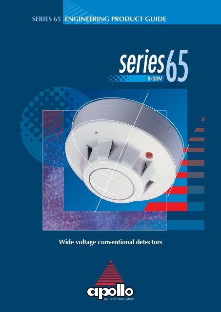
SERIES 65 ENGINEERING PRODUCT GUIDE<br />
Wide voltage conventional detectors
Series 65 incorporates well-proven sensing<br />
technologies, including an IC based on that used<br />
in XP95 analogue addressable detectors.<br />
The Series 65 range has a wide operating voltage<br />
of 9–33V and consists of ionisation, integrating<br />
ionisation and optical smoke detectors, four<br />
grades of heat detector and a range of bases.<br />
This product guide aims to provide engineers with<br />
comprehensive information on Series 65, in order<br />
to be able to design optimum solutions to fire<br />
protection problems.<br />
Apollo Fire Detectors <strong>Ltd</strong>, part of the Halma plc<br />
group of companies, operates from one site at<br />
Havant, near Portsmouth, England. All<br />
departments – Research and Development, Sales<br />
and Marketing, Manufacturing and Finance – are<br />
located here. Apollo applies the most modern<br />
production techniques and has invested in<br />
sophisticated manufacturing equipment to ensure<br />
consistent high quality of product and fast<br />
response to customer requirements. Through<br />
planned expansion Apollo has reached a leading<br />
position in the market for professional fire<br />
detectors and exports over half of its production<br />
to countries around the world.<br />
Apollo Fire Detectors is certified to ISO9001:2000<br />
by the Loss Prevention Certification Board.<br />
Information in this guide is given in good faith, but Apollo Fire<br />
Detectors Limited cannot be held responsible for any omissions<br />
or errors. The company reserves the right to change<br />
specifications of products at any time without prior notice.
SERIES 65 TABLE OF CONTENTS<br />
Ionisation Smoke Detector<br />
Operating principles 4<br />
Integrating version 5<br />
Options 5<br />
Safety note 5<br />
Environmental characteristics 5<br />
Technical data 6<br />
Optical Smoke Detector<br />
Operating principles 7<br />
Options 7<br />
Technical data 8<br />
Heat Detector<br />
Operating principles 9<br />
Options 9<br />
Response tine 10<br />
Technical data 11<br />
Mounting Base<br />
Specification 12<br />
page<br />
3<br />
Mini Disc Remote Indicator<br />
Specification 13<br />
Interchangeability 14<br />
Control Panel Compatibility 14<br />
EMC 14<br />
Approvals and Regulatory Compliance 14
SERIES 65 IONISATION SMOKE DETECTOR<br />
page<br />
4<br />
Series 65 Standard Ionisation Smoke Detector<br />
▲ Part nos<br />
Ionisation detector 55000-217<br />
Detector with flashing LED 55000-216<br />
Detector with reed switch & flashing LED 55000-215<br />
Series 65 Integrating Ionisation Smoke Detector<br />
Ionisation detector 55000-220<br />
Detector with flashing LED 55000-219<br />
Detector with reed switch & flashing LED 55000-218<br />
OPERATING<br />
PRINCIPLES<br />
The detector has a moulded<br />
self-extinguishing white<br />
polycarbonate case with<br />
wind resistant smoke inlets.<br />
Nickel plated stainless steel<br />
wiper contacts connect the<br />
detector to the base.<br />
Inside the detector case a<br />
printed circuit board has the<br />
ionisation chamber mounted<br />
on one side and the signal<br />
processing electronics on<br />
the other.<br />
The ionisation chamber<br />
consists of a reference<br />
chamber contained inside a<br />
smoke chamber (Fig. 1). The<br />
outer smoke chamber has<br />
inlet apertures fitted with<br />
insect resistant mesh. The<br />
radioactive source holder<br />
and smoke chamber form<br />
positive and negative<br />
electrodes respectively.<br />
An Americium 241<br />
radioactive source mounted<br />
within the reference chamber<br />
irradiates the air in both<br />
chambers, producing<br />
positive and negative ions. A<br />
voltage across the electrodes<br />
produces an electric field.<br />
Ions are attracted to the<br />
electrode of the opposite sign<br />
to their own charge. Many<br />
recombine but a small electric<br />
current flows between the<br />
electrodes. At the junction<br />
between reference and smoke<br />
chambers the sensing<br />
electrode converts variations<br />
in chamber current into<br />
voltage changes.<br />
When smoke particles enter<br />
the ionisation chamber ions<br />
become attached to them<br />
with the result that the current<br />
flowing through the chambers<br />
decreases. This effect is<br />
greater in the smoke chamber<br />
than in the reference<br />
chamber, and the imbalance<br />
causes the sensing electrode<br />
to become more positive.<br />
The voltage at the sensing<br />
electrode is fed to a<br />
comparator where it is<br />
compared with a factory-set<br />
clean air reference voltage. If<br />
the monitored voltage exceeds<br />
the reference voltage, the<br />
comparator switches the<br />
alarm latch on, increasing the<br />
current drawn from the<br />
supply from about 40µA to a<br />
maximum of 75mA. This fall<br />
in the impedance of the<br />
detector is recognised by the<br />
Lid moulding<br />
Reference chamber<br />
PCB<br />
Smoke chamber<br />
Inner cover<br />
control panel as an alarm<br />
signal.<br />
The alarm latch current also<br />
illuminates the detector<br />
integral LED. A remote<br />
indicator connected between<br />
the L1 IN terminal and the –R<br />
terminal will have a voltage<br />
equal to the supply voltage<br />
less 1 volt across it and so<br />
will illuminate. See page 13<br />
for details of the remote<br />
indicator.<br />
To ensure correct operation<br />
of the detector the control<br />
panel must be arranged to<br />
supply a maximum of 33<br />
volts DC and a minimum<br />
of 9 volts DC in normal<br />
operation.<br />
The supply may fall to 6 volts<br />
DC in alarm conditions if a<br />
supply current of at least<br />
10mA is available at this<br />
voltage. To ensure effective<br />
illumination of the integral<br />
LED and any remote indicator,<br />
the supply to the detector<br />
should exceed 12 volts.<br />
To restore the detector to<br />
quiescent condition, it is<br />
necessary to expel any<br />
smoke and interrupt the<br />
electrical supply to the<br />
detector for a minimum of<br />
one second.<br />
Positive supply on foil holder<br />
Radioactive foil<br />
Integrated circuit<br />
0V<br />
LED<br />
Sensing<br />
electrode<br />
Fig.1<br />
Side view, Series 65 Optical Smoke Detector
INTEGRATING<br />
VERSION<br />
Circuitry in the Integrating<br />
Ionisation Smoke Detector<br />
protects against transient<br />
levels of smoke above the<br />
normal threshold level for 10<br />
to 20 seconds. The sensitivity<br />
of the detector is not affected<br />
by this modification.<br />
OPTIONS<br />
(Apply to standard and<br />
integrating versions)<br />
1. Flashing LED: The alarm<br />
indicating LED flashes<br />
when the detector is in a<br />
quiescent state.<br />
2. Reed Switch and Flashing<br />
LED: A reed switch in the<br />
circuit of the detector can<br />
be magnetically activated<br />
from outside the case to<br />
initiate an alarm<br />
condition for test and<br />
commissioning purposes.<br />
A flashing LED, as<br />
outlined above, is also<br />
included.<br />
SAFETY NOTE<br />
In the United Kingdom,<br />
ionisation smoke detectors<br />
are subject to the<br />
requirements of the<br />
Radioactive Substances Act<br />
1993 and to the Ionising<br />
Radiations Regulations 1999<br />
made under the provisions of<br />
the Health and Safety at<br />
Work Act 1974.<br />
The detectors, independently<br />
tested by the National<br />
Radiological Protection<br />
Board (NRPB), conform to all<br />
the requirements specified in<br />
the ‘Recommendations for<br />
ionisation smoke detectors in<br />
implemetation of radiation<br />
standards’ published by the<br />
Nuclear Energy Agency of<br />
the Organisation for<br />
Economic Co-operation and<br />
Development (OECD) 1977.<br />
There is no limit to the<br />
number of ionisation smoke<br />
detectors which may be<br />
installed in any fire protection<br />
system within the United<br />
Kingdom. See Certificate of<br />
Approval no TA1 issued by<br />
the Health & Safety Executive<br />
for further details.<br />
Storage regulations depend<br />
on local standards and<br />
legislation, but, in the UK,<br />
the number of ionisation<br />
smoke detectors in any<br />
building or premises shall be<br />
less than 500. See Certificate<br />
of Approval no TA3 of 1999<br />
issued by the Health & Safety<br />
Executive for further details.<br />
At the end of their<br />
recommended working life<br />
of ten years, ionisation<br />
smoke detectors should be<br />
returned to Apollo for safe<br />
disposal or disposed of in an<br />
otherwise locally approved<br />
and environmentally safe<br />
manner. Please see “A guide<br />
to the care, maintenance and<br />
servicing of Apollo<br />
products”, PP2055.<br />
Guidance on storage and<br />
handling can be given by<br />
Apollo Fire Detectors and full<br />
details can be requested<br />
from:<br />
Radioactive Substances<br />
Regulation Function<br />
Environment Agency<br />
Rio House<br />
Waterside Drive<br />
Aztec West, Almondsbury<br />
Briston BS32 4UD<br />
Outside the UK, please<br />
contact the relevant national<br />
agency.<br />
ENVIRONMENTAL<br />
CHARACTERISTICS<br />
Series 65 ionisation smoke<br />
detectors operate over a<br />
temperature range of –20°C<br />
to +60°C.<br />
Ionisation detectors have<br />
some sensitivity to air<br />
movement (wind). The extent<br />
to which the sensor output<br />
will change depends on the<br />
wind speed and on the<br />
orientation of the detector<br />
relative to the wind direction.<br />
Relatively small changes in<br />
wind direction can cause<br />
significant changes in sensor<br />
output.<br />
For wind speeds up to 1m/s<br />
(200ft/min) sensitivity will<br />
change by less than 20%.<br />
Continuous operation in<br />
wind speeds greater than<br />
2m/s (400ft/min) is not<br />
recommended. However,<br />
wind speeds up to 10m/s<br />
(2000ft/min) can be tolerated<br />
for short periods and will not<br />
under any conditions<br />
increase the probability of<br />
false alarms.<br />
Series 65 ionisation smoke<br />
detectors are supplied in<br />
individual packing with a red<br />
lid serving as a dust cover<br />
which can be left in place<br />
after fitting to prevent ingress<br />
of foreign material until<br />
commissioning of the system<br />
takes place. At this point the<br />
covers must be removed.<br />
page<br />
5
page<br />
6<br />
TECHNICAL DATA<br />
Specifications are typical<br />
and given at 23°C and 50%<br />
relative humidity unless<br />
specified otherwise.<br />
Detector Type:<br />
Point type smoke detector<br />
for fire detection and alarm<br />
systems for buildings<br />
Detection Principle:<br />
Ionisation chamber<br />
Chamber Configuration:<br />
Twin compensating<br />
chambers using one singlesided<br />
ionising radiation<br />
source<br />
Radioactive Isotope:<br />
Americium 241<br />
Activity:<br />
33.3 k Bq, 0.9 µCi<br />
Supply Wiring:<br />
Two wire monitored supply,<br />
polarity insensitive<br />
Terminal Functions:<br />
L1 IN and L2: supply in<br />
connections (polarity<br />
insensitive)<br />
L1 OUT and L2:<br />
supply out connections<br />
(polarity insensitive).<br />
–R:<br />
remote indicator negative<br />
connection<br />
Supply Voltage:<br />
9 to 33V DC<br />
Ripple Voltage:<br />
2V peak to peak maximum<br />
at 0.1Hz to 100kHz<br />
Quiescent Current:<br />
20–45µA at 24V<br />
Switch-on Surge Current:<br />
110µA<br />
Alarm Voltage:<br />
6 to 33V<br />
Normal Alarm Current:<br />
61mA at 28V<br />
52mA at 24V<br />
18mA at 10V<br />
Alarm Indicator:<br />
Red, Light Emitting Diode<br />
(LED)<br />
Design Alarm Load:<br />
420Ω in series with a 2V<br />
drop<br />
Holding Voltage:<br />
6V (min)<br />
Holding Current:<br />
10mA (min)<br />
Minimum Voltage Required<br />
to Illuminate Indicator:<br />
12V<br />
Alarm Reset Time:<br />
1 second<br />
Remote Output<br />
Characteristics:<br />
Remote is a current sink to<br />
the negative line limited to<br />
17mA<br />
Calibration:<br />
Factory set to ∆V of 0.8V<br />
Sensitivity:<br />
Nominal threshold Y value<br />
of 0.7 to EN 54–7: 2000<br />
Temperature Range:<br />
Maximum continuous<br />
operating temperature 60°C<br />
Minimum continuous<br />
operating temperature 0°C<br />
Minimum operating<br />
temperature –20°C<br />
(no condensation or icing)<br />
Storage –30°C to +80°C<br />
Temperature Compensation:<br />
Automatic compensation by<br />
dual chambers to comply<br />
with EN 54–7: 2000 across<br />
the operating temperature<br />
range<br />
Humidity:<br />
0% to 95% relative humidity<br />
(no condensation)<br />
Atmospheric Pressure:<br />
Automatic compensation by<br />
dual chambers to maintain<br />
sensitivity up to a height of<br />
2000m<br />
Wind Speed:<br />
10m/s maximum<br />
IP Rating:<br />
23D in accordance with<br />
BS EN 60529<br />
EMC, approvals and<br />
regulatory compliance:<br />
Refer to Page 14 of this<br />
document<br />
Dimensions: (dia. x height)<br />
Detector: 100x42mm<br />
Detector in Base: 100x50mm<br />
Weights:<br />
Detector: 102g<br />
Detector in Base: 153g<br />
Materials:<br />
Detector housing: White<br />
polycarbonate rated V-0 in<br />
accordance with UL 94.<br />
Terminals: Nickel plated<br />
stainless steel<br />
CE 3852<br />
Alarm Reset Voltage:<br />
1V<br />
technical data
SERIES 65 OPTICAL SMOKE DETECTOR<br />
Optical Smoke Detector<br />
▲ Part nos<br />
Standard detector 55000-317<br />
Detector with flashing LED 55000-316<br />
Detector with reed switch & flashing LED 55000-315<br />
OPERATING<br />
PRINCIPLES<br />
The Series 65 Optical Smoke<br />
Detector has a moulded selfextinguishing<br />
white<br />
polycarbonate case with<br />
wind resistant smoke inlets.<br />
Nickel plated stainless steel<br />
wiper contacts connect the<br />
detector to the base. Inside<br />
the case a printed circuit<br />
board has the optical system<br />
mounted on one side and<br />
the signal processing<br />
electronics on the other.<br />
The sensing chamber is a<br />
black moulding configured<br />
as a labyrinth which<br />
prevents penetration of<br />
ambient light. The labyrinth<br />
has a fine gauze insectresistant<br />
cover. The chamber<br />
houses an infrared light<br />
emitting diode (LED) and a<br />
photo-diode which has an<br />
integral visible-light filter as<br />
extra protection against<br />
ambient light.<br />
Every 3 seconds the LED<br />
emits a burst of collimated<br />
light, modulated at 4kHz. In<br />
clear air, light from the LED<br />
does not fall directly on the<br />
diode because the LED is<br />
positioned at an obtuse<br />
angle to the diode (as<br />
shown in Fig 2).<br />
When smoke enters the<br />
chamber, a fraction of the<br />
collimated light is scattered<br />
onto the photo-diode. If the<br />
resulting signal from the<br />
photo-diode is above a<br />
preset threshold, the LED<br />
emits two more bursts of<br />
light, this time at two-second<br />
intervals. If light is scattered<br />
onto the photo-diode by<br />
both these pulses – due to<br />
the presence of smoke – the<br />
detector signals an alarm<br />
state by switching the alarm<br />
latch on, increasing the<br />
current drawn from the<br />
supply from about 40µA to a<br />
maximum of 75mA. This fall<br />
in the impedance of the<br />
detector is recognised by the<br />
control panel as an alarm<br />
signal.<br />
The alarm current also<br />
illuminates the detector<br />
integral LED. A remote<br />
indicator connected<br />
between the L1 IN terminal<br />
and the –R terminal will<br />
have a voltage equal to the<br />
supply voltage less 1 volt<br />
across it and so will<br />
illuminate.<br />
To ensure correct operation<br />
of the detector the control<br />
panel must be arranged to<br />
supply a maximum of 33<br />
volts DC and a minimum of<br />
9 volts DC in normal<br />
operation. The supply may<br />
OPTICAL CHAMBER<br />
PCB COVER<br />
CASE MOULDING<br />
fall to 6 volts DC in alarm<br />
conditions if a supply<br />
current of at least 10mA is<br />
available at this voltage. To<br />
ensure effective illumination<br />
of the integral LED and any<br />
remote indicator, the supply<br />
to the detector should<br />
exceed 12 volts.<br />
To restore the detector to<br />
quiescent condition, it is<br />
necessary to expel any<br />
smoke and interrupt the<br />
electrical supply to the<br />
detector for a minimum of<br />
one second.<br />
OPTIONS<br />
1. Flashing LED: The<br />
integral LED flashes<br />
when the detector is in a<br />
quiescent state.<br />
2. Reed Switch and<br />
Flashing LED: A reed<br />
switch in the circuit of<br />
the detector can be<br />
magnetically activated<br />
from outside the case to<br />
initiate an alarm<br />
condition for test and<br />
commissioning<br />
purposes. A flashing<br />
LED, as outlined above,<br />
is also included.<br />
PHOTO-DIODE<br />
INFRA-RED LED<br />
page<br />
7<br />
© Apollo Fire Detectors LImited 1991/RHD<br />
Fig.2<br />
Top section, Series 65 Optical Smoke Detector
page<br />
8<br />
TECHNICAL DATA<br />
Specifications are typical<br />
and given at 23°C and 50%<br />
relative humidity unless<br />
specified otherwise.<br />
Detector Type:<br />
Point type smoke detector<br />
for fire detection and alarm<br />
systems for buildings<br />
Detection Principle:<br />
Photo-electric detection of<br />
light scattered in a forward<br />
direction by smoke particles<br />
Chamber Configuration:<br />
Horizontal optical bench<br />
housing an infra-red emitter<br />
and sensor arranged radially<br />
to detect forward scattered<br />
light<br />
Sensor:<br />
Silicon PIN photo-diode<br />
Emitter:<br />
GaAs Infra-red light emitting<br />
diode<br />
Sampling Frequency:<br />
Once every 3 seconds<br />
Confirmation Frequency:<br />
Once every 3 seconds<br />
Number of Consecutive<br />
Sensed Alarm Signals<br />
Needed To Trigger<br />
Detector Alarm:<br />
3<br />
Supply Wiring:<br />
Two wire monitored supply,<br />
polarity insensitive<br />
Terminal Functions:<br />
L1 IN and L2: supply in<br />
connections (polarity<br />
insensitive).<br />
L1 OUT and L2:<br />
supply out connections<br />
(polarity insensitive).<br />
–R:<br />
remote indicator negative<br />
connection<br />
Supply Voltage:<br />
9 to 33V DC<br />
Ripple Voltage:<br />
2V peak to peak maximum<br />
at 0.1Hz to 100kHz<br />
Quiescent Current:<br />
30–50µA at 24V<br />
Switch-on Surge Current:<br />
115µA at 24V<br />
Alarm Voltage:<br />
6 to 28V<br />
Normal Alarm Current:<br />
61mA at 28V<br />
52mA at 24V<br />
18mA at 10V<br />
Alarm Indicator:<br />
Clear light emitting diode<br />
(LED) emitting red light<br />
Design Alarm Load:<br />
420Ω in series with 2V drop<br />
Holding Voltage:<br />
6V (min)<br />
Holding Current:<br />
10mA (min)<br />
Minimum Voltage Required<br />
to Illuminate Indicator:<br />
12V<br />
Alarm Reset Voltage:<br />
1V<br />
Alarm Reset Time:<br />
1 second<br />
Remote Output<br />
Characteristics:<br />
Remote is a current sink to<br />
the negative line limited to<br />
17mA<br />
Sensitivity:<br />
Nominal alarm threshold of<br />
0.15dB/m obscuration,<br />
measured in accordance<br />
with EN 54–7: 2000<br />
Temperature Range:<br />
–20° to +60°C<br />
(no condensation or icing).<br />
Humidity:<br />
0% to 95% relative<br />
humidity (no condensation)<br />
Wind Speed:<br />
Insensitive to wind<br />
Atmospheric Pressure:<br />
Insensitive to atmospheric<br />
pressure<br />
Wind Speed:<br />
10m/s maximum<br />
IP Rating:<br />
23D in accordance with<br />
BS EN 60529<br />
EMC, approvals and<br />
regulatory compliance:<br />
Refer to Page 14 of this<br />
document<br />
Dimensions: (dia. x height)<br />
Detector: 100x42mm<br />
Detector in Base: 100x50mm<br />
Weights:<br />
Detector: 99g<br />
Detector in Base: 150g<br />
Materials:<br />
Detector housing: White<br />
polycarbonate rated V-0 in<br />
accordance with UL 94.<br />
Terminals: Nickel plated<br />
stainless steel<br />
CE 3852<br />
technical data
SERIES 65 HEAT DETECTOR<br />
Series 65 Heat Class A1R<br />
▲ Part nos<br />
Standard detector 55000-122<br />
Detector with flashing LED 55000-121<br />
Detector with reed switch & flashing LED 55000-120<br />
Series 65 Heat Class BR<br />
Standard detector 55000-127<br />
Detector with flashing LED 55000-126<br />
Detector with reed switch & flashing LED 55000-125<br />
Series 65 Heat Class CR<br />
Standard detector 55000-132<br />
Detector with flashing LED 55000-131<br />
Detector with reed switch & flashing LED 55000-130<br />
Series 65 Heat Class CS<br />
Standard detector 55000-137<br />
Detector with flashing LED 55000-136<br />
Detector with reed switch & flashing LED 55000-135<br />
OPERATING<br />
PRINCIPLES<br />
The detector has a moulded<br />
self-extinguishing white<br />
polycarbonate case. Nickel<br />
plated stainless steel wiper<br />
contacts connect the<br />
detector to the base. Inside<br />
the case a printed circuit<br />
board holds the signal<br />
processing electronics.<br />
A pair of matched negative<br />
temperature coefficient<br />
thermistors are mounted on<br />
the PCB in such a way that<br />
one thermistor is exposed to<br />
give good thermal contact<br />
with the surrounding air<br />
while the other thermistor is<br />
thermally insulated.<br />
Under stable conditions<br />
both thermistors are in<br />
thermal equilibrium and<br />
have the same value of<br />
resistance. If air temperature<br />
increases rapidly the<br />
resistance of the exposed<br />
thermistor becomes less<br />
than that of the insulated<br />
thermistor. The ratio of the<br />
resistance of the thermistors<br />
is monitored electronically<br />
and an alarm is initiated if<br />
the ratio exceeds a factory<br />
preset level. This feature<br />
determines the ‘rate of rise’<br />
response of the detector.<br />
If air temperature increases<br />
slowly, no significant<br />
resistance difference<br />
develops between the<br />
thermistors, but at high<br />
temperatures a fixed value<br />
resistance connected in<br />
series with the insulated<br />
thermistor becomes<br />
significant.<br />
When the sum of the<br />
resistance of the insulated<br />
thermistor and the fixed<br />
resistor compared to the<br />
resistance of the exposed<br />
thermistor reaches a preset<br />
value, an alarm is initiated.<br />
The value of the fixed<br />
resistor is selected to set the<br />
detector into alarm state at a<br />
specified fixed temperature.<br />
The detector signals an<br />
alarm state by switching an<br />
alarm latch on, increasing<br />
the current drawn from the<br />
supply from about 50µA to<br />
a maximum of about 75mA.<br />
This fall in the impedance<br />
of the detector is recognised<br />
by the control panel as an<br />
alarm signal.<br />
The alarm current also<br />
illuminates the detector<br />
integral LED. A remote<br />
indicator connected<br />
between the L1 IN terminal<br />
and the –R terminal will<br />
have a voltage equal to the<br />
supply voltage less 1 volt<br />
across it and so will<br />
illuminate.<br />
To ensure correct operation<br />
of the detector the control<br />
panel must be arranged to<br />
supply a maximum of 33<br />
volts DC and a minimum of<br />
9 volts DC in normal<br />
operation. The supply may<br />
fall to 6 volts DC in alarm<br />
conditions if a supply<br />
current of at least 10mA is<br />
available at this voltage.<br />
To ensure effective<br />
illumination of the integral<br />
LED and any remote<br />
indicator, the supply to the<br />
detector should exceed 12<br />
volts.<br />
To restore the detector to<br />
quiescent condition, it is<br />
necessary to restore a<br />
normal temperature level<br />
and interrupt the electrical<br />
supply to the detector for a<br />
minimum of one second.<br />
OPTIONS<br />
1. Flashing LED: The<br />
integral LED flashes<br />
when the detector is in a<br />
quiescent state.<br />
2. Reed Switch and<br />
Flashing LED: A reed<br />
switch in the circuit of<br />
the detector can be<br />
magnetically activated<br />
from outside the case to<br />
initiate an alarm<br />
condition for test and<br />
commissioning<br />
purposes. A flashing<br />
LED, as outlined above,<br />
is also included.<br />
page<br />
9
page<br />
10<br />
RESPONSE TIME<br />
European Standard<br />
EN54–5:2000 classifies<br />
heat detectors according<br />
to the alarm temperature<br />
and ambient operating<br />
temperature.<br />
Each heat detector<br />
classification has a static<br />
response (changing to alarm<br />
at a preset temperature) and<br />
may also have a rate of rise<br />
response (changing to alarm<br />
at or above a preset<br />
increase of temperature).<br />
The heat detector classes<br />
available in Series 65 are<br />
A1R, BR, CR, CS.<br />
The suffix R indicates that<br />
the detector has been tested<br />
and approved as a ‘rate-ofrise’<br />
detector. The suffix ‘S’<br />
indicates that the detector<br />
has been tested and<br />
approved as a ‘static’<br />
detector.<br />
Supply<br />
Voltage<br />
(V)<br />
Table 1<br />
A1R Standard<br />
A1R Flashing LED<br />
A1R Flashing LED/<br />
Reed Switch<br />
Quiescent Alarm Quiescent Alarm Quiescent Alarm<br />
24 45µA 52mA 55µA 52mA 55µA 52mA<br />
9 40µA 17mA 50µA 17mA 50µA 17mA<br />
Class<br />
Typical current against voltage charateristics for quiescent and alarm states<br />
Max<br />
application<br />
temperature<br />
°C<br />
Max static<br />
response<br />
temperature<br />
°C<br />
Standard<br />
Part number<br />
Flashing LED<br />
Flashing LED/<br />
Reed Switch<br />
A1R 50 65 55000-122 55000-121 55000-120<br />
BR 65 85 55000-127 55000-126 55000-125<br />
CR 80 100 55000-132 55000-131 55000-130<br />
Table 2<br />
CS 80 100 55000-137 55000-136 55000-135<br />
Series 65 Heat Detector Temperatures and part numbers<br />
Fig. 3<br />
Choosing a heat detector
TECHNICAL DATA<br />
Specifications are typical<br />
and given at 23°C and 50%<br />
relative humidity unless<br />
otherwise specified.<br />
Detector Type:<br />
Point type heat detector for<br />
fire detection and alarm<br />
systems for buildings<br />
Supply Wiring:<br />
Two wire monitored supply,<br />
polarity insensitive<br />
Terminal Functions:<br />
L1 IN and L2:<br />
supply in connections<br />
(polarity insensitive).<br />
L1 OUT and L2:<br />
supply out connections<br />
(polarity insensitive)<br />
–R:<br />
remote indicator negative<br />
connection<br />
Supply Voltage:<br />
9 to 33V<br />
Ripple Voltage:<br />
2V peak to peak maximum<br />
at 0.1 Hz to 100 kHz<br />
Quiescent Current:<br />
See table 1<br />
Switch-on Surge Current:<br />
As per Quiescent Current<br />
Alarm Voltage:<br />
6 to 28V<br />
Alarm Current:<br />
See table 1<br />
Alarm Indicator:<br />
Red light emitting diode<br />
Design Alarm Load:<br />
420Ω in series with a 2V<br />
drop<br />
Holding Voltage:<br />
6V<br />
Minimum Voltage Required<br />
to Light Alarm Indicator:<br />
12V<br />
Remote Output<br />
Characteristics:<br />
Remote is a current sink to<br />
the negative line limited to<br />
17mA<br />
Storage Temperature<br />
Range:<br />
–30°C to 120°C.<br />
Operating Temperature:<br />
–20°C to +90°C (no icing)<br />
Humidity:<br />
0% to 95% relative<br />
humidity<br />
Atmospheric Pressure:<br />
Unaffected<br />
IP Rating:<br />
23D in accordance with BS<br />
EN 60529<br />
EMC, approvals and<br />
regulatory compliance:<br />
Refer to Page 14 of this<br />
document<br />
Dimensions: (dia. x height)<br />
Detector: 100x42mm<br />
Detector in Base: 100x50mm<br />
Weights:<br />
Detector:<br />
80g<br />
Detector in Base: 131g<br />
Materials:<br />
Detector housing: White<br />
polycarbonate rated V-0 in<br />
accordance with UL 94.<br />
Terminals: Nickel plated<br />
stainless steel<br />
CE 3852<br />
Holding<br />
technical<br />
Current:<br />
data<br />
10mA<br />
page<br />
11
SERIES 65 MOUNTING BASE<br />
Series 65 Mounting Base<br />
▲<br />
page<br />
12<br />
SPECIFICATION<br />
Full details of all bases and<br />
accessories are given in<br />
PP1089. All detectors in the<br />
Series 65 range fit into Series<br />
60 standard mounting bases.<br />
The bases are of 100mm<br />
diameter and have five<br />
terminals marked according<br />
to their function: Line 1 in,<br />
line 1 out, line 2 in and out,<br />
remote indicator negative,<br />
earth.<br />
Detectors are polarity<br />
insensitive, so that<br />
identification of positive and<br />
negative lines is only required<br />
if a remote LED is fitted.<br />
An earth connection is not<br />
required for either safety or<br />
correct operation of detectors.<br />
The earth terminal is<br />
provided for tidy termination<br />
of earthed conductors or<br />
cable screens and to<br />
maintain earth continuity<br />
where necessary.<br />
Bases have a wide interior<br />
diameter for ease of access<br />
to cables and terminals and<br />
there are two slots for fixing<br />
screws at a spacing of 51 to<br />
69mm.<br />
Detectors fit into bases one<br />
way only and require<br />
clockwise rotation without<br />
push force to be plugged in.<br />
They can be locked into the<br />
base by a grub screw using a<br />
1.5mm hexagonal driver,<br />
part no 29600-095.<br />
OPTIONS<br />
For conventional systems<br />
which are required to<br />
operate normally when one<br />
or more detector heads have<br />
been removed, a base with a<br />
Schottky diode in LINE 1 is<br />
available (part no. 45681-<br />
201). The diode conducts<br />
when the associated detector<br />
is removed, allowing power<br />
to reach devices<br />
downstream. Active<br />
monitoring can be used in<br />
systems with diode bases.
SERIES 65 MINI DISC REMOTE INDICATOR<br />
Mini Disc Remote Indicator<br />
▲<br />
SPECIFICATION<br />
page<br />
13<br />
The MiniDisc remote<br />
indicator is only 20mm high<br />
and 80mm in diameter. It<br />
comprises two parts–the base<br />
which is installed onto a wall<br />
or soffit and the lid which is<br />
fitted to the base with a<br />
bayonet lock.<br />
An anti-tamper screw in the<br />
lid locks the unit together. A<br />
1.5mm hexagonal driver, part<br />
number 29600-095, is<br />
available from Apollo.<br />
Two pairs of keyholes are<br />
provided–one for 50mm and<br />
the other for 60mm fixing<br />
centres.<br />
The MiniDisc Remote<br />
Indicator is polarity sensitive.<br />
Connect positive line to<br />
Terminal A or B and negative<br />
line to Terminal C.<br />
+<br />
From<br />
control<br />
panel<br />
–<br />
Fig.3<br />
L1 IN<br />
L1OUT<br />
EARTH<br />
L2<br />
—R<br />
L1 IN<br />
L1OUT<br />
EARTH<br />
L2<br />
—R<br />
L1 IN<br />
—R<br />
L1OUT End-of-line<br />
device<br />
EARTH<br />
L2<br />
Schematic wiring diagram of Series 65 monitored detector<br />
circuit with a common remote indicator.<br />
Remote LED<br />
+<br />
From<br />
control<br />
panel<br />
L1 IN<br />
L1OUT<br />
EARTH<br />
L2<br />
—R<br />
L1 IN<br />
L1OUT<br />
EARTH<br />
L2<br />
—R<br />
L1 IN<br />
L1OUT<br />
EARTH<br />
L2<br />
—R<br />
End-of-line<br />
device<br />
–<br />
Fig.4<br />
Schematic wiring diagram of Series 65 monitored<br />
detector circuit
page<br />
14<br />
INTERCHANGEABILITY<br />
Any detector in the Series 65<br />
range may be replaced with<br />
any other type in the range.<br />
If, for example, a smoke<br />
detector proved unsuitable<br />
for a particular application,<br />
it could simply be replaced<br />
with a heat detector.<br />
The bases are designed<br />
specifically for Series 65<br />
detectors and will not accept<br />
devices from other Apollo<br />
product ranges, including<br />
earlier Apollo models but<br />
with the expection of<br />
Series 60.<br />
CONTROL PANEL<br />
COMPATIBILITY<br />
Series 65 has been designed<br />
to be connected to any<br />
conventional control panel<br />
that will operate existing<br />
ranges of Apollo<br />
conventional detectors.<br />
When engineering systems<br />
with Series 65, it should be<br />
borne in mind that the alarm<br />
impedance of a detector be<br />
considered as 420 Ohms in<br />
series with a 2 volt drop<br />
with LED open circuit.<br />
Typical current against<br />
voltage characteristics for<br />
quiescent and alarm states<br />
for heat detectors are shown<br />
in Table 1.<br />
EMC<br />
All Series 65 detectors and<br />
relay bases comply with the<br />
requirements of the<br />
following EMC standards:<br />
Generic Emission Standard<br />
EN 61000–6–3 Emission<br />
standards for residential,<br />
commercial and light<br />
industrial environments<br />
Generic Emission Standard<br />
EN 61000–6–4 Emission<br />
standards for industrial<br />
environments<br />
EN 50130–4: Alarm Systems<br />
Electromagnetic compatibility<br />
– product family standard:<br />
immunity requirements for<br />
components of fire, intruder<br />
and social alarm systems<br />
EN 61000–4–2<br />
Electrostatic discharge<br />
EN 61000–4–3<br />
Radiated immunity<br />
EN 61000–4–4<br />
Fast transient bursts<br />
EN 61000–4–5<br />
Surge immunity<br />
EN 61000–4–6<br />
Conducted immunity<br />
All standard detectors and<br />
the relay bases have been<br />
assessed to the additional<br />
VdS EMC requirements shown<br />
below and have demonstrated<br />
full compliance:<br />
30V/m with 80% Am sine<br />
and 100% pulse modulation<br />
depth over the frequency<br />
ranges 415 to 467MHz and<br />
890 to 960 MHz.<br />
Series 65 optical detector,<br />
part no 55000-317, and heat<br />
detector, part no 55000-122,<br />
have been declared to be<br />
compliant with the standard<br />
EN 50155: Railway<br />
applications : Electronic<br />
equipment used on rolling<br />
stock.<br />
APPROVALS AND<br />
REGULATORY<br />
COMPLIANCE<br />
The Series 65 range of<br />
detectors and relay bases is<br />
approved by a large number<br />
of certification bodies.<br />
These include approvals to<br />
EN54 : 2000 with LPCB,<br />
VdS, DIBT, BOSEC, and FG.<br />
For further information on<br />
approvals held by<br />
Apollo contact us on<br />
sales@apollo-fire.co.uk or<br />
phone 023 9249 2412.<br />
Information on approvals is<br />
also held on our website<br />
www.apollo-fire.co.uk<br />
Series 65 complies with the<br />
requirements of a number of<br />
European New Approach<br />
Directives such as the EMC<br />
Directive 89/336/EEC and<br />
the Construction Products<br />
Directive 89/106/EEC. Visit<br />
the Apollo website to view<br />
EC certificates of conformity<br />
issued by LPCB as a<br />
Notified Body. Copies of<br />
Declarations of Conformity<br />
issued by Apollo for all<br />
applicable New Approach<br />
Directives are available<br />
from Apollo on request.<br />
All Series 65 products will<br />
comply with the marking<br />
requirements of the WEEE<br />
Directive, 2002/96/EC. For<br />
further information on<br />
disposing of applicable<br />
electrical and electronic<br />
waste contact Apollo<br />
directly.
PP2061/2005/Issue 1<br />
© Apollo Fire Detectors <strong>Ltd</strong> 1999 - 2005<br />
Assessed to ISO 9001: 2000<br />
Certificate number 010<br />
36 Brookside Road, Havant, Hampshire PO9 1JR, UK. Tel: +44 (0)23 9249 2412. Fax: +44 (0)23 9249 2754.<br />
Email: sales@apollo-fire.co.uk Website: www.apollo-fire.co.uk<br />
Apollo GmbH, Am Anger 31, 33332 Gütersloh, Germany. Tel: +49 5241 33060. Fax: +49 5241 330629<br />
Air Products and Controls Inc., 1749 E Highwood, Pontiac, MI 48340, USA. Tel: +1 248 332 3900. Fax: +1 248 332 8807