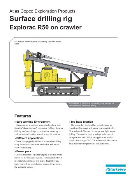
Surface drilling rig Explorac R50 on crawler - Atlas Copco
Surface drilling rig Explorac R50 on crawler - Atlas Copco
Surface drilling rig Explorac R50 on crawler - Atlas Copco

You also want an ePaper? Increase the reach of your titles
YUMPU automatically turns print PDFs into web optimized ePapers that Google loves.
<strong>Atlas</strong> <strong>Copco</strong> Explorati<strong>on</strong> Products<br />
<str<strong>on</strong>g>Surface</str<strong>on</strong>g> <str<strong>on</strong>g>drilling</str<strong>on</strong>g> <str<strong>on</strong>g>rig</str<strong>on</strong>g><br />
<str<strong>on</strong>g>Explorac</str<strong>on</strong>g> <str<strong>on</strong>g>R50</str<strong>on</strong>g> <strong>on</strong> <strong>crawler</strong><br />
It is a robust and reliable drill unit, making it ideal for remote<br />
areas.<br />
It is designed to perform an outstanding base platform for<br />
“down-the-hole” percussi<strong>on</strong> <str<strong>on</strong>g>drilling</str<strong>on</strong>g>.<br />
Features<br />
»»Safe Working Envir<strong>on</strong>ment<br />
• It is designed to perform an outstanding base platform<br />
for ”down-the-hole” percussi<strong>on</strong> <str<strong>on</strong>g>drilling</str<strong>on</strong>g>. Separate<br />
drill <str<strong>on</strong>g>rig</str<strong>on</strong>g> subframe design permits stable mounting <strong>on</strong><br />
various standard carriers as well as special vehicles.<br />
»»Different applicati<strong>on</strong>s<br />
• It can be equipped for mineral explorati<strong>on</strong> <str<strong>on</strong>g>drilling</str<strong>on</strong>g><br />
using the reverse circulati<strong>on</strong> method as well as for<br />
water well <str<strong>on</strong>g>drilling</str<strong>on</strong>g>.<br />
»»Power pack<br />
• A deck mounted 4-cylinder engine is used as prime<br />
mover for the hydraulic system. The model BF4L914<br />
is a naturally aspirated, four cycle, direct injected,<br />
turbo charged, air-cooled diesel engine, for powering<br />
the hydraulic pumps.<br />
»»Top head rotati<strong>on</strong><br />
• The heavy duty top head has been designed to<br />
provide <str<strong>on</strong>g>drilling</str<strong>on</strong>g> speed and torque characteristics for<br />
”down-the-hole” hammer technique and light rotary<br />
<str<strong>on</strong>g>drilling</str<strong>on</strong>g>. The rotati<strong>on</strong> head is a single reducti<strong>on</strong> oil<br />
bath gear box, ratio 3,89:1, equipped with two hydraulic<br />
motors type OMT 250 as standard. The motors<br />
have maximum torque at near stall c<strong>on</strong>diti<strong>on</strong>s.
Quick reference<br />
<str<strong>on</strong>g>Explorac</str<strong>on</strong>g> range<br />
<str<strong>on</strong>g>Explorac</str<strong>on</strong>g> <str<strong>on</strong>g>R50</str<strong>on</strong>g> C Unit ready to drill <strong>crawler</strong> mounted, external compressor<br />
<str<strong>on</strong>g>Explorac</str<strong>on</strong>g> <str<strong>on</strong>g>R50</str<strong>on</strong>g> T Unit ready to drill truck mounted with <strong>on</strong>board mudpump and external compressor<br />
Specificati<strong>on</strong>s<br />
Mast<br />
• Mast overall length .....................................................6 200 mm<br />
• Feed travel length.........................................................4 400 mm<br />
• Max distance between floating sub and break-out table<br />
......................................................................................4 200 mm<br />
• Drill pipe std length.....................................................3 000 mm<br />
The out<str<strong>on</strong>g>rig</str<strong>on</strong>g>gers, mast tilt and slide are operated from a separate<br />
valve block located <strong>on</strong> the <str<strong>on</strong>g>rig</str<strong>on</strong>g>ht hand side of the <str<strong>on</strong>g>rig</str<strong>on</strong>g>.<br />
• Out<str<strong>on</strong>g>rig</str<strong>on</strong>g>gers, Bore ..............................................................80 mm<br />
• Pist<strong>on</strong> rod..........................................................................50 mm<br />
• Stroke..............................................................................900 mm<br />
• Tilt cylinder, Bore...........................................................100 mm<br />
• Pist<strong>on</strong> rod..........................................................................50 mm<br />
• Stroke..............................................................................600 mm<br />
• Slide cylinder, Bore...........................................................80 mm<br />
• Pist<strong>on</strong> rod..........................................................................40 mm<br />
• Stroke .............................................................................800 mm<br />
Feed system<br />
The feed system is activated by <strong>on</strong>e hydraulic traverse cylinder<br />
mounted inside the mast. The force is transmitted to the<br />
top head by a heavy duty chain.<br />
• Feed cylinder stroke ....................................................2 200 mm<br />
• Pist<strong>on</strong> Ø ..........................................................................100 mm<br />
• Pist<strong>on</strong> rod Ø ..................................................................63,5 mm<br />
• Feed force (theor.) .......................................................... 48,8 kN<br />
• Pull down speed, slow ...............................................16,8 m/min<br />
• Pull down speed, rapid ..............................................48,2 m/min<br />
• Pull up capacity (theor.) ................................................. 80,9 kN<br />
• Pull up speed, slow ...................................................10,2 m/min<br />
• Pull up speed, rapid ...................................................29,1 m/min<br />
Rotati<strong>on</strong> unit (Top head)<br />
Main shaft Alloy steel with 50 mm through hole<br />
• Rotati<strong>on</strong> input power......................................................... 38 kW<br />
• Torque max. at 210 bar with standard two motors....... 5 750 Nm<br />
• Speed range for standard motors.................................0 – 97 rpm<br />
• Floating spindle............................................................................<br />
Direct flanged to gear box with3 ½” reg box thread.<br />
Winch<br />
• Pull capacity, empty drum.................................................. 17 kN<br />
• Rope speed, empty drum............................................18,6 m/min<br />
• Wire rope supplied..............................................30 m, Ø 10 mm<br />
Air system and lubricator<br />
• A complete 50 mm (2 in) air system for 25 bar (360 psi) pressure<br />
is mounted <strong>on</strong> the <str<strong>on</strong>g>rig</str<strong>on</strong>g>. There is also a pressure regulator<br />
c<strong>on</strong>nected to a branch line reducing maximum outlet pressure to<br />
7 bar (100 psi) for simultaneously running of opti<strong>on</strong>al pneumatic<br />
equipment when high pressure is used for the <str<strong>on</strong>g>drilling</str<strong>on</strong>g> operati<strong>on</strong>.<br />
• An in-line lubricator is mounted in the air line for lubricating<br />
percussi<strong>on</strong> tools. An oil tank with 10 lit capacity is included as<br />
well.<br />
• Use <strong>on</strong>ly lubricati<strong>on</strong> oil recommended by tool manufacturer.<br />
• Check that oil actually reaches the hammer before <str<strong>on</strong>g>drilling</str<strong>on</strong>g><br />
starts.<br />
C<strong>on</strong>trol panel<br />
Following c<strong>on</strong>trols and instruments are mounted in the c<strong>on</strong>trol<br />
panel<br />
• Slow and rapid feed c<strong>on</strong>trol including press. gauges<br />
• Rotati<strong>on</strong> c<strong>on</strong>trol and press. gauge<br />
• Rotati<strong>on</strong> speed c<strong>on</strong>trol<br />
• Feed and hold back press.<br />
• Winch c<strong>on</strong>trol<br />
• Valves, air press. gauge, main air valve, rpm counter, panel<br />
light and emergency stop<br />
• C<strong>on</strong>trols for opti<strong>on</strong>al equipment are also installed in the panel<br />
Work light / electrical system<br />
The 24V electric system is c<strong>on</strong>nected to the separate diesel<br />
engine. Circuits are protected by fuses.<br />
• Alternator .......................................................... 27A, 28V<br />
• Lights<br />
• mast ................................................. 2 x 100W floodlights<br />
• c<strong>on</strong>trol panel ......................................2 x 5W panel lights<br />
• work area ..........................................1 x 100W floodlight<br />
• work area ............................................1 x 24W floodlight<br />
Crawler<br />
The <str<strong>on</strong>g>rig</str<strong>on</strong>g> unit is mounted <strong>on</strong> a not oscillating <strong>crawler</strong> chassi<br />
with hydraulically driven axial pist<strong>on</strong> type motors.<br />
• Hyd. motor displacement ................................................. 32 cm 3<br />
• Reducti<strong>on</strong> gear ratio ...................................................... 115,5 : 1<br />
• Speed <strong>on</strong> level ground ..............................................2,4 km/hour<br />
• This opti<strong>on</strong> adds appr. .................................................. 2 790 kg.<br />
Technical specificati<strong>on</strong> <str<strong>on</strong>g>Explorac</str<strong>on</strong>g> <str<strong>on</strong>g>R50</str<strong>on</strong>g> Crawler
Specificati<strong>on</strong>s<br />
Power pack<br />
A deck mounted turbo charged 4-cylinder Deutz engine is<br />
used as prime mover for the hydraulic system.<br />
• Model ................................................................ Deutz BF4L914<br />
• Number of cylinders ................................................................. 4<br />
• Power .........................................................69 kW at 2300 r/min<br />
• Torque ......................................................355 Nm at 1600 r/min<br />
• Displacement ...................................................................4,3 dm 3<br />
• Fuel c<strong>on</strong>sumpti<strong>on</strong> .......... 225g/kWh at max torque, 12,7 lit/hour<br />
• Fuel tank volume .................................................................90 lit<br />
• Air cleaner .....Dry heavy duty with replaceable main and safety<br />
elements with dust load indicator.<br />
• Engine safety................................................................................<br />
Low oil pressure, high oil temperature and V-belt failure.<br />
• Installati<strong>on</strong> includes.....................................................................<br />
24 V electrical system, fuel filters, lube oil filter, instruments<br />
and c<strong>on</strong>trols, muffler and heavy duty base.<br />
Hydraulic system<br />
All <str<strong>on</strong>g>drilling</str<strong>on</strong>g> and associated functi<strong>on</strong>s are powered by an open<br />
loop hydraulic system. Three pumps, two fixed gear pumps<br />
and <strong>on</strong>e variable volume pist<strong>on</strong> pump, of heavy duty type<br />
provide a l<strong>on</strong>g trouble free operati<strong>on</strong>. All hydraulic circuits<br />
are protected by safety valves.<br />
• Fixed wing pump for rotati<strong>on</strong> circuit...........................................<br />
...............................25VQTxxx12 max. flow 92 lit/min, 40 cm 3 /r<br />
• Fixed wing pump for rapid feed and auxiliary functi<strong>on</strong>s circuit,<br />
................................ V20xxx11 max. flow 82 lit/min, 35,7 cm3/r<br />
• Variable pist<strong>on</strong> pump for slow feed circuit..................................<br />
..................................................................... max. flow 25 lit/min<br />
•<br />
• Rated volumes refer to 2300 rpm with separate diesel engine<br />
power pack.<br />
Oil cooler<br />
A heat exchanger package provides cooling for the hydraulic<br />
oil system. The system is thermostatically c<strong>on</strong>trolled to maintain<br />
minimum operating temperatures.<br />
• System design temp. ........................................................... 48ºC<br />
• Cooling fan size .........................................................Ø 538 mm<br />
• Cooling fan speed .................................................... 2 200 r/min<br />
• Fan drive ......................................................................hydraulic<br />
Rotati<strong>on</strong> motor alternatives<br />
• The standard rotati<strong>on</strong> unit is equipped with dual hydraulic<br />
motors as per alternative 7 below. By selecting different size of<br />
motors, different torque and rpm opti<strong>on</strong>s will be available. There<br />
is a choice of using a single motor or dual motors with a selector<br />
valve. Below table illustrates the different opti<strong>on</strong>s.<br />
Motor type RPM Torque<br />
Dual motor OMT Nm kpm<br />
Alt 1 160 0-148 1860 190 serie<br />
0-75 3725 380 parallel<br />
Alt 2 200 0-120 2310 236 serie<br />
0-60 4630 472 parallel<br />
Alt 3 250 0-97 2870 293 serie<br />
0-46 5750 586 parallel<br />
Alt 4 315 0-74 3725 380 serie<br />
0-37 7470 762 parallel<br />
Helpers platform<br />
On the <str<strong>on</strong>g>rig</str<strong>on</strong>g>ht side of the mast a helpers platform is mounted to<br />
simplify handling of drill pipes.<br />
• This opti<strong>on</strong> adds appr. ............................................ 120 kg<br />
Water / Foam injecti<strong>on</strong> pump<br />
The water injecti<strong>on</strong> pump CAT1010 type has an incorporated<br />
pulse pump with independent supply lines for water<br />
and foam c<strong>on</strong>centrate. The pump is driven by a hydraulic<br />
gear type motor. Water is supplied from external supply.<br />
Valves for operati<strong>on</strong> of the pump and metering of mixture are<br />
mounted <strong>on</strong> the operators c<strong>on</strong>trol panel.<br />
A sucti<strong>on</strong> hose ¾”, 3m l<strong>on</strong>g, with foot valve for use of separate<br />
tank or barrel is provided separately. A hose with quick<br />
coupling and nozzle for washing purpose is included.<br />
• Max flow ..................................................................... 45 lit/min<br />
• Max pressure .....................................................................30 bar<br />
• Rpm ....................................................................................... 900<br />
• This opti<strong>on</strong> adds appr. ....................................................... 70 kg.<br />
Hold back scale<br />
The hold back gauge can is fitted with a scale ring. When the<br />
drill string is balanced the scale is set and when <str<strong>on</strong>g>drilling</str<strong>on</strong>g> starts<br />
(hold back pressure reduced) the correct bit load can be read<br />
off the scale.<br />
Fixed pipe rack<br />
A fixed pipe rack mounts <strong>on</strong> <str<strong>on</strong>g>rig</str<strong>on</strong>g>ht hand side of the <str<strong>on</strong>g>rig</str<strong>on</strong>g>. Can<br />
hold up to 20 pcs of 114 mm (4 ½”) OD drill pipes.<br />
Technical specificati<strong>on</strong>s <str<strong>on</strong>g>Explorac</str<strong>on</strong>g> <str<strong>on</strong>g>R50</str<strong>on</strong>g> Crawler
Opti<strong>on</strong>al equipment<br />
JIB boom, fixed explorati<strong>on</strong><br />
For handling drill pipe <strong>on</strong> angles up to 30 º from vertical. The<br />
fixed boom is manually pinned in positi<strong>on</strong> to suit the choosen<br />
angle of <str<strong>on</strong>g>drilling</str<strong>on</strong>g>. This opti<strong>on</strong> requires the helpers platform as<br />
well as the winch kit for RC pipe handling.<br />
The winch is hydraulically driven and mounted <strong>on</strong> the boom.<br />
• Operating angle: ..........................................................................<br />
0 – 30 º , mast is manually locked in 5 º increments.<br />
• Jib boom capacity ............................................................ 2,5 kN<br />
• This opti<strong>on</strong> adds appr. ....................................................... 60 kg.<br />
Alternative mast<br />
The standard mast for 3 m drill pipe can be replaced by a<br />
l<strong>on</strong>ger mast to accomodate 6m l<strong>on</strong>g drill pipe.<br />
• Mast overall length ............................................................8,8 m<br />
• Feed travel length ...............................................................7,0 m<br />
• Max distance between floating sub and B-O table..............6,8 m<br />
• Drill pipe length ......................................................6,0 m (20 ft)<br />
• This opti<strong>on</strong> adds appr. ..................................................... 700 kg.<br />
Cycl<strong>on</strong>e<br />
A cycl<strong>on</strong>e is located at the <str<strong>on</strong>g>rig</str<strong>on</strong>g>ht rear of the machine. Cycl<strong>on</strong>e<br />
assembly reduces the velocity of the cuttings to allow<br />
complete sample recovery. The cycl<strong>on</strong>e can, if desired, be<br />
delivered separatly free standing. An air operated cylinder<br />
activates a door releasing the sample.<br />
• The assembly includes a 3” hose c<strong>on</strong>necting the top head and<br />
the cycl<strong>on</strong>e and a duct diverting hose<br />
• Capacity ....................... 350 lit/sec (750 cfm), 3 ½”,4½” system<br />
• This opti<strong>on</strong> adds appr. ..................................................... 300 kg.<br />
Three tiers riffle splitter<br />
Used in c<strong>on</strong>juncti<strong>on</strong> with the cycl<strong>on</strong>e, the splitter provides a<br />
method to reduce the volume of the collected material, while<br />
maintaining a representative sample.<br />
• This opti<strong>on</strong> adds appr. ....................................................... 90 kg.<br />
Saver sub<br />
To the rotati<strong>on</strong> head is a floating sub flanged and the floating<br />
sub has a 3 ½” reg box tool joint.<br />
In order to minimize wear and tear of the floating sub it is<br />
recommended to use a saver sub. In additi<strong>on</strong> the saver sub<br />
can functi<strong>on</strong> as a cross over sub to pin instead of box or<br />
another type of thread.<br />
• This opti<strong>on</strong> adds appr. .............................................. 10 kg<br />
Holding spanners<br />
Holding keys, manually inserted, fitting into the break-out<br />
table are available in a range of sizes to fit key slots <strong>on</strong> drill<br />
pipes, DTH drills, subs, collars, stabilizers etc.<br />
• This opti<strong>on</strong> adds appr. ...............................................10 kg each.<br />
Bit breaker plates<br />
Bit breaker plates are designed to fit in the break-out table to<br />
keep drill bit from rotating or falling through when the tool<br />
joint is loosened. Specify bit type, size and manufacturer. If<br />
not available, bit breaker plates can be supplied blank (bit<br />
profile not cut into the plate) for final fitting in the field.<br />
• This opti<strong>on</strong> adds appr. .................................................7 kg each.<br />
Top head for RC Drilling<br />
A standard <str<strong>on</strong>g>Explorac</str<strong>on</strong>g> <str<strong>on</strong>g>R50</str<strong>on</strong>g> top head is adapted to a 4 ½”, 4”<br />
or 3 ½” RC <str<strong>on</strong>g>drilling</str<strong>on</strong>g> system. Designed for using dual tube<br />
reverse circulati<strong>on</strong> air <str<strong>on</strong>g>drilling</str<strong>on</strong>g> method. The cuttings are<br />
c<strong>on</strong>veyed to the surface through the top head and collected.<br />
A special discharge swivel and top head shaft wear sleeve are<br />
provided with this opti<strong>on</strong>. Side inlet swivel is not included in<br />
this item. Floating sub is not provided.<br />
• Head wear tube ID 40 mm ................................3 ½” RC system<br />
• 50 mm ..................................................................................... 4”<br />
• 50 mm ................................................................................. 4 ½”<br />
• This opti<strong>on</strong> adds appr. ..................................................... 120 kg.<br />
Break out table inserts<br />
There are two sizes of inserts, 203 mm and 150 mm standard<br />
delivered with the <str<strong>on</strong>g>rig</str<strong>on</strong>g>. To guide selected drill pipes inserts<br />
are available for 114 mm, 100 mm, 89 mm and 76 mm. Other<br />
sizes are available <strong>on</strong> request.<br />
• This opti<strong>on</strong> adds appr. .................................................30 kg/ set.<br />
Side inlet swivel (less sub)<br />
Introduces the flushing air into the dual pipe annulus and<br />
ports the sample cuttings through the top head for collecti<strong>on</strong>.<br />
Includes installati<strong>on</strong> to the top head, but not sub for the drill<br />
pipe.<br />
Model 3 ½” 4” 4 ½”<br />
Upper thread:<br />
Lower thread:<br />
3 ½” RC<br />
Metzke box<br />
3 ½” RC<br />
Metzke pin<br />
4” RC Metzke<br />
box<br />
4” RC Metzke<br />
short pin<br />
4” RC Metzke<br />
l<strong>on</strong>g box<br />
4 ½” RC<br />
Metzke pin<br />
Side port: 1 ½” BSP 2 ½” NPT 2 ½” NPT<br />
I.D. of shaft: 62,3 mm 68,6 mm 68,6 mm<br />
• This opti<strong>on</strong> adds appr. ........................................................ 30 kg<br />
Technical specificati<strong>on</strong> <str<strong>on</strong>g>Explorac</str<strong>on</strong>g> <str<strong>on</strong>g>R50</str<strong>on</strong>g> Crawler
Technical specificati<strong>on</strong>s <str<strong>on</strong>g>Explorac</str<strong>on</strong>g> <str<strong>on</strong>g>R50</str<strong>on</strong>g> Crawler
Measurements & weights<br />
3510<br />
2510<br />
2550<br />
4000<br />
2480<br />
© Copy<str<strong>on</strong>g>rig</str<strong>on</strong>g>ht 20XX, <strong>Atlas</strong> <strong>Copco</strong> Craelius AB, Märsta Sweden. Any unauthorized use or copying of the c<strong>on</strong>tents or any part thereof is prohibited. This applies in<br />
particular to trademarks, model denominati<strong>on</strong>s, part numbers and drawings. Illustrati<strong>on</strong>s and photos in this document may show equipment with opti<strong>on</strong>al extras.<br />
Specificati<strong>on</strong>s and equipment subjects to change without notice. C<strong>on</strong>sult your <strong>Atlas</strong> <strong>Copco</strong> Customer Center for specific informati<strong>on</strong>.<br />
6580<br />
Dimensi<strong>on</strong>s<br />
Crawler versi<strong>on</strong> (kg)<br />
Drill <str<strong>on</strong>g>rig</str<strong>on</strong>g> 7 010* * Ready to drill RC applicati<strong>on</strong><br />
Carrier 2 790<br />
Total: 9 800<br />
6991 5021 01 Märsta,Sweden, 14 June 2009<br />
<strong>Atlas</strong> <strong>Copco</strong> Geotechnical Drilling and Explorati<strong>on</strong><br />
www.atlascopco.com