MSAN 81-242 - BTK
MSAN 81-242 - BTK
MSAN 81-242 - BTK

You also want an ePaper? Increase the reach of your titles
YUMPU automatically turns print PDFs into web optimized ePapers that Google loves.
SPLIT SYSTEM<br />
<strong>81</strong> - <strong>242</strong><br />
<strong>MSAN</strong> <strong>81</strong>-<strong>242</strong><br />
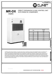
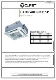
AIR COOLED CONDENSING UNIT HEAT PUMP VERSION FOR OUTDOOR INSTALLATION<br />
<strong>MSAN</strong> <strong>81</strong> - <strong>242</strong> (R-407C)<br />
Size<br />
Cooling<br />
Heating<br />
[kW]<br />
[kW]<br />
<strong>81</strong> 21.8 22.6<br />
91 25.8 26.7<br />
101 30.9 31.7<br />
121 37.6 38.9<br />
142 39.2 42.0<br />
162 44.1 45.9<br />
182 50.3 54.6<br />
202 62.8 65.2<br />
<strong>242</strong> 72.8 77.7<br />
REPLACE: BT02E003GB-02<br />
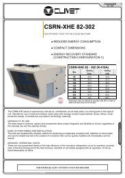
These units are the outdoor section of a "SPLIT SYSTEM" installation. They can be matched either to our CED, CED-V, UVCN-V (cooling<br />
only) CN, CN-V, UVCN-V (heat pump) series or to the exchange coil of air handling units. The combination of low speed propeller fans<br />
with external rotor, a specially designed compressor housing with acoustic and thermal insulation, the variable fan speed and the<br />
"SCROLL" compressors, makes the <strong>MSAN</strong> units particularly silent. The unit compactness allow an easy installation even in reduced<br />
available space. All units are equipped with a new microprocessor control system optimising their performances.<br />
BT04G011GB-01(EC1)<br />
CERTIFIED QUALITY SYSTEM ISO 9001 : 2008
SPLIT SYSTEM<br />
<strong>81</strong> - <strong>242</strong><br />
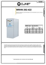
The condensing unit versatile for every application<br />
ELECTRONIC CONTROL MODULE- including the<br />
display to show the operating status and separate<br />
display of the alarms (high pressure - low pressure -<br />
compressor overload - condenser probe) - condenser<br />
control according to the outside air temperature<br />
(modulating variation of the fan speed) - defrost<br />
control - compressor operating hour counter - possibility<br />
of connection to supervisor<br />
high and low pressure gauges<br />
high efficiency scroll compressors<br />
CONNECTION KIT<br />
Unit supplied complete with kit for the connection of<br />
the refrigerant circuit and the dewatering filter<br />
BT04G011GB-00<br />
A special detail in the refrigerant circuit of the<br />
outside unit prevents the formation of frost on the<br />
bottom of the air exchanger during operation in<br />
heat pump mode. If the ICE PROTECTION<br />
SYSTEM is not sufficient, the controller starts the<br />
defrost cycles. During the defrost phase, an<br />
auxiliary heater installed on the indoor unit is<br />
activated so as to prevent the introduction of cold<br />
air into the room.<br />
2
SPLIT SYSTEM<br />
<strong>81</strong> - <strong>242</strong><br />
STANDARD UNIT SPECIFICATIONS<br />
COMPRESSOR<br />
hermetic orbiting scroll compressor complete with motor over-temperature and<br />
over-current devices and protection against excessive gas discharge<br />
temperature. Fitted on rubber antivibration mounts and complete with oil<br />
charge<br />
STRUCTURE<br />
structure made from “aluzink” plate, providing excellent mechanical<br />
characteristics and extensive corrosion strength<br />
PANELLING<br />
external panels in prepainted aluminium especially indicated in outdoor<br />
installation due to its superior resistance to corrosion avoiding periodic<br />
painting. Side panels are easily removable and allow complete access to unit<br />
components. Internal sound proof lining reduces sound pressure levels.<br />
EXTERNAL EXCHANGER<br />
direct expansion finned exchanger, made from copper pipes in staggered rows<br />
and mechanically expanded to the fin collars. The fins are made from<br />
aluminium with a corrugated surface and adequately distanced to ensure the<br />
maximum heat exchange efficiency.<br />
FAN<br />
Low speed axial fan directly driven by single phase external rotor motor with<br />
incorporated thermal overload. Housed in aerodynamically shaped enclosures<br />
to increase the efficiency and reduce the noise level. Complete with fan guard<br />
in order to help against fortuitous contact with the blades.<br />
compressor power supply remote control switch<br />
compressor fuses<br />
auxiliary circuit fuse<br />
compressor overload protection and timer<br />
current limiter for compressor protection<br />
microprocessor control section:<br />
compressor overload protection and timer<br />
Separate alarms visualization (high pressure, low pressure, overload<br />
compressor, probe breakdown).<br />
centralised alarms with remote signalling<br />
condenser control allows the unit to operate, in coolnig only, at low outside air<br />
temperatures ( temperature actuated fans speed control).<br />
compressor and unit operating hour counter<br />
Free contacts for cumulative signals of the alarms and defrost state.<br />
defrost management<br />
ACCESSORIES<br />
copper / aluminium condenser coils with acrylic lining<br />
copper / copper condenser coils<br />
finned coil protection grill.<br />
remote keypad (TR)<br />
serial communication module to supervisor (MODBUS)<br />
phase monitor to check the presence and correct sequence of the power<br />
supply phases<br />
pressure-type low outside temperature device<br />
rubber antivibration mounts<br />
connecting set: thermal expansion valve, filter dryer, sight glass, check valve.<br />
REFRIGERANT CIRCUIT<br />
The circuit is complete with:<br />
high pressure switch<br />
low pressure switch<br />
liquid and gas shut-off valves with service fitting<br />
high compressor discharge temperature safety thermostat<br />
4-way reverse cycle valve<br />
liquid receiver<br />
Ice Protection System: system to prevent ice on the bottom of air coil<br />
high and low pressure gauges<br />
expansion device<br />
non-return valve<br />
ELECTRICAL PANEL<br />
Terminals for the link to internal unit and power supply .<br />
main line isolator switch<br />
CONFIGURATION CODE<br />
<strong>MSAN</strong>-2 S <strong>81</strong> ST T<br />
(1) VERSION<br />
Standard (S)<br />
standard<br />
(2) ACOUSTIC CONFIGURATION<br />
Standard (ST)<br />
see description on page 2<br />
1 2 3<br />
(3) ENERGY EFFICIENCY<br />
Temperate Climate (T)<br />
standard<br />
BT04G011GB-00<br />
CONVERSION TABLE : DEW / MID POINT<br />
DP (°C)<br />
3<br />
5<br />
7<br />
8<br />
9.5<br />
12<br />
THE FOLLOWING VALUES ARE REFERRED TO DEW POINT. AN INDICATION OF THE<br />
CORRESPONDING MEDIUM EVAPORATING TEMPERATURE (MID POINT) IS GIVEN IN THE TABLE.<br />
MP (°C)<br />
1<br />
3<br />
5<br />
6<br />
7.5<br />
10<br />
3
SPLIT SYSTEM<br />
<strong>81</strong> - <strong>242</strong><br />
GENERAL TECHNICAL SPECIFICATIONS<br />
COOLING<br />
Cooling capacity 1 kW 21.79 25.84 30.92 37.56 39.2 44.1 50.3 62.8 72.8<br />
Compressor power input 1 kW 6.53 8.31 9.25 11.7 12.6 14.7 17.8 20.3 25.2<br />
Total power input 1 kW 6.82 8.6 9.83 12.28 13.4 15.5 18.6 21.5 26.4<br />
HEATING<br />
Heat output 2 kW 22.62 26.72 31.74 38.86 42 45.9 54.6 65.2 77.7<br />
Compressor power input 2 kW 4.83 5.94 6.82 8.32 8.3 9.7 11.9 13.6 16.6<br />
Total power input 2 kW 5.12 6.23 7.4 8.9 9.1 10.5 12.7 14.8 17.8<br />
COMPRESSOR<br />
Type of compressors<br />
SCROLL SCROLL SCROLL SCROLL SCROLL SCROLL SCROLL SCROLL SCROLL<br />
No. of Compressors Nr 1 1 1 1 2 2 2 2 2<br />
Std Capacity control steps Nr 1 1 1 1 2 2 2 2 2<br />
Oil charge (C1) l 4.1 4.1 4.1 4.1 1.8 4.1 4.1 4.1 4.1<br />
Oil charge (C2) l 0 0 0 0 1.8 4.1 4.1 4.1 4.1<br />
Refrigerant charge (C1) 3 kg 6.4 6.5 9.6 9.8 6.5 6.8 9 9.6 9.8<br />
Refrigerant charge (C2) 3 kg 0 0 0 0 6.5 6.8 9 9.6 9.8<br />
Refrigerant circuits Nr 1 1 1 1 2 2 2 2 2<br />
EXTERNAL SECTION FANS<br />
Number of fans Nr 2 2 4 4 4 4 4 6 6<br />
Standard air flow l/s 2286 2286 3622 3424 4230 4230 4230 6100 6100<br />
Installed unit power kW 0.145 0.145 0.145 0.145 0.15 0.15 0.15 0.15 0.15<br />
CONNECTIONS<br />
Gas connection 28 28 35 35 28 28 28 35 35<br />
Liquid connection 18 18 22 22 16 18 18 22 22<br />
POWER SUPPLY<br />
Standard power supply V 400/3/50+N 400/3/50+N 400/3/50+N 400/3/50+N 400/3/50+N 400/3/50+N 400/3/50+N 400/3/50+N 400/3/50+N<br />
DIMENSIONS<br />
Length mm 1373 1373 1573 1573 1563 1563 1563 2098 2098<br />
Depth mm 557 557 557 557 1107 1107 1107 1107 1107<br />
Height mm 1225 1225 1225 1225 1570 1570 1570 1570 1570<br />
(1) saturated suction temperature (SST) = 9.5 °C (Dew Point)<br />
outside air temperature 35°C<br />
(2) external exchanger air intake = 6.1 °C W.B.<br />
condensing temperature = 40°C<br />
(3) charge to be completed during start-up<br />
SOUND LEVELS<br />
BT04G011GB-00<br />
Acoustic configuration: Standard (ST)<br />
Size<br />
Sound Power Level (dB)<br />
Octave band (Hz)<br />
Sound<br />
pressure<br />
level<br />
Sound<br />
power level<br />
63 125 250 500 1000 2000 4000 8000 dB(A) dB(A)<br />
<strong>81</strong> 84 80 76 72 69 67 63 60 60 75<br />
91 83 78 78 74 69 69 60 55 61 76<br />
101 78 84 77 76 70 64 59 52 60 76<br />
121 77 80 80 73 67 71 60 63 61 77<br />
142 87 80 74 73 71 69 66 63 60 77<br />
162 87 <strong>81</strong> 76 73 70 69 65 62 60 77<br />
182 84 78 78 74 69 70 62 55 60 77<br />
202 86 79 78 77 72 67 62 54 61 78<br />
<strong>242</strong> 86 82 <strong>81</strong> 75 70 73 63 65 62 79<br />
the sound levels refer to the unit at full load, in the rated test conditions.<br />
The sound pressure level refers to a distance of 1m from the external surface of the<br />
units operating in an open field.<br />
4
Voltage: 400/3/50+N<br />
SPLIT SYSTEM<br />
<strong>81</strong> - <strong>242</strong><br />
ELECTRICAL DATA<br />
Size <strong>81</strong> 91 101 121 142 162 182 202 <strong>242</strong><br />
F.L.A. - FULL LOAD CURRENT AT MAX ADMISSIBLE CONDITIONS<br />
F.L.A. - Total A 15.98 18.78 22.58 26.78 30 32.2 37.8 42.8 53.2<br />
F.L.I. FULL LOAD POWER INPUT AT MAX ADMISSIBLE CONDITION<br />
F.L.I. - Total kW 8.7 10.9 12.5 15.2 15.8 17.4 21.3 24.7 30.1<br />
M.I.C. MAXIMUM INRUSH CURRENT<br />
M.I.C. - Value A 95.7 118.9 129.8 161.3 118.2 111.3 136.6 151.4 188.1<br />
ELECTRICAL DATA<br />
Voltage: 400/3/50<br />
Size <strong>81</strong> 91 101 121 142 162 182 202 <strong>242</strong><br />
F.L.A. - FULL LOAD CURRENT AT MAX ADMISSIBLE CONDITIONS<br />
F.L.A. - Compressor 1 A 14.65 17.45 20.04 24.28 13.6 14.7 17.5 20 25.2<br />
F.L.A. - Compressor 2 A 0 0 0 0 13.6 14.7 17.5 20 25.2<br />
F.L.A. - Single External Fan A 0.64 0.64 0.64 0.64 0.7 0.7 0.7 0.7 0.7<br />
F.L.A. - Total A 15.93 18.73 22.6 26.84 30 32.2 37.8 42.8 53.2<br />
L.R.A. LOCKED ROTOR AMPERES<br />
L.R.A. - Compressor 1 A 94 116.5 127.5 159 102 94 116.5 127.5 159<br />
L.R.A. - Compressor 2 A 0 0 0 0 102 94 116.5 127.5 159<br />
F.L.I. FULL LOAD POWER INPUT AT MAX ADMISSIBLE CONDITION<br />
F.L.I. - Compressor 1 kW 8.4 10.35 11.89 14.61 7.6 8.4 10.4 11.9 14.6<br />
F.L.I. - Compressor 2 kW 0 0 0 0 7.6 8.4 10.4 11.9 14.6<br />
F.L.I. - Single External Fan kW 0.15 0.15 0.15 0.15 0.15 0.15 0.15 0.15 0.15<br />
F.L.I. - Total kW 8.7 10.7 12.5 15.2 15.8 17.4 21.3 24.7 30.1<br />
M.I.C. MAXIMUM INRUSH CURRENT<br />
M.I.C. - Value A 95.28 117.78 130.06 161.56 118.2 111.3 136.6 151.4 188.1<br />
power supply: 400/3/50 Hz +/-6%<br />
voltage unbalance: max 2 %<br />
ELECTRICAL DATA<br />
Voltage: 230/3/50<br />
Size <strong>81</strong> 91 101 121 142 162 182 202 <strong>242</strong><br />
F.L.A. - FULL LOAD CURRENT AT MAX ADMISSIBLE CONDITIONS<br />
F.L.A. - Compressor 1 A 24.1 31.2 35.8 45.2 25.3 24.1 31.2 35.8 45.2<br />
F.L.A. - Compressor 2 A 0 0 0 0 25.3 24.1 31.2 35.8 45.2<br />
F.L.A. - Single External Fan A 0.64 0.64 0.64 0.64 0.7 0.7 0.7 0.7 0.7<br />
F.L.A. - Total A 25.38 32.48 38.36 47.76 53.3 50.8 65 75.5 94.3<br />
L.R.A. LOCKED ROTOR AMPERES<br />
L.R.A. - Compressor 1 A 166 210.5 224 279.5 171 166 210.5 224 279.5<br />
L.R.A. - Compressor 2 A 0 0 0 0 171 166 210.5 224 279.5<br />
F.L.I. FULL LOAD POWER INPUT AT MAX ADMISSIBLE CONDITION<br />
F.L.I. - Compressor 1 kW 8.4 10.35 11.89 14.61 7.6 8.4 10.4 11.9 14.6<br />
F.L.I. - Compressor 2 kW 0 0 0 0 7.6 8.4 10.4 11.9 14.6<br />
F.L.I. - Single External Fan kW 0.15 0.15 0.15 0.15 0.15 0.15 0.15 0.15 0.15<br />
F.L.I. - Total kW 8.7 10.65 12.49 15.21 15.8 17.4 21.3 24.7 30.1<br />
M.I.C. MAXIMUM INRUSH CURRENT<br />
M.I.C. - Value A 167.28 211.78 226.56 282.06 198.9 192.7 244.3 263.7 328.6<br />
OPERATING LIMITS (COOLING)<br />
Size <strong>81</strong> 91 101 121 142 162 182 202 <strong>242</strong><br />
EXTERNAL EXCHANGER<br />
Max air intake temperature 1 °C 47 46 46 46 45 44.5 42.5 46 43<br />
Min. air intake temperature 2 °C -10 -10 -10 -10 -5 -5 -9 -5 -9<br />
COMPRESSOR<br />
Max saturated suction temperature (SST) °C 14.5 14.5 14.5 14.5 14.5 14.5 14.5 14.5 14.5<br />
Minimum saturated suction temperature (SST) °C 2 2 2 2 2 2 2 2 2<br />
BT04G011GB-00<br />
OPERATING LIMITS (HEATING)<br />
EXTERNAL EXCHANGER<br />
Max air temperature inlet (WB) 3 °C 18 18 18 18 18 18 18 18 18<br />
Min air inlet temperature (W.B.) °C -6 -6 -6 -6 -6 -6 -6 -6 -6<br />
Max condensing temperature 4 °C 64 64 64 64 64 64 64 64 64<br />
Min. condensing temperature °C 30 30 30 30 30 30 30 30 30<br />
DB = dry bulb<br />
WB = wet bulb<br />
In case of below zero air ambient temperature with a long period of heat pump operating<br />
mode it is necessary to help the evacuation of the water produced during the defrost cycle;<br />
this to avoid the formation of ice in the unit basement. Pay attention that the evacuation will<br />
not create inconveniences to things or persons.<br />
(1) saturated suction temperature (SST) = 7°C (Dew Point)<br />
suction gas superheating +5° K<br />
(2) external exchanger air in quiet<br />
(3) condensing temperature = 45°C<br />
(4) air 10°C DB / 8.3 °C WB<br />
5
SPLIT SYSTEM<br />
<strong>81</strong> - <strong>242</strong><br />
ACOUSTIC CONFIGURATION: STANDARD (ST)<br />
COOLING PERFORMANCE<br />
Size<br />
SST<br />
(°C)<br />
EXTERNAL EXCHANGER AIR TEMPERATURE (°C)<br />
25 30 32 35 43<br />
kWf kWe kWf kWe kWf kWe kWf kWe kWf kWe kWf kWe<br />
46<br />
3<br />
19.8 4.99 18.7 5.52 18.2 5.76 17.5 6.12 15.6 7.18 14.9 7.62<br />
5<br />
21.2 5.08 20.0 5.62 19.5 5.86 18.8 6.23 16.8 7.32 16.1 7.77<br />
<strong>81</strong><br />
7<br />
8<br />
22.6 5.18 21.4 5.74 20.8 5.98 20.1 6.36 18.1 7.48 17.3 7.94<br />
23.4 5.24 22.0 5.80 21.5 6.04 20.8 6.43 18.7 7.56 18.0 8.03<br />
9.5<br />
24.5 5.32 23.1 5.90 22.6 6.14 21.8 6.53 19.8 7.70 19.0 8.18<br />
12<br />
26.4 5.48 24.9 6.07 24.4 6.33 23.6 6.74 21.5 7.95<br />
3<br />
23.6 6.48 22.3 7.18 21.7 7.48 20.9 7.94 18.6 9.26 17.8 9.80<br />
5<br />
25.3 6.59 23.8 7.29 23.2 7.59 22.4 8.06 20.0 9.39 19.0 9.93<br />
91<br />
7<br />
8<br />
27.0 6.69 25.4 7.40 24.8 7.70 23.9 8.17 21.3 9.52 20.4 10.1<br />
27.8 6.75 26.3 7.46 25.6 7.76 24.7 8.23 22.0 9.58<br />
9.5<br />
29.2 6.82 27.5 7.54 26.9 7.84 25.8 8.31 23.1 9.67<br />
12<br />
31.5 6.95 29.7 7.67 29.0 7.97 27.9 8.44 24.9 9.80<br />
3<br />
27.9 7.19 26.3 7.98 25.7 8.31 24.7 8.83 22.1 10.3 21.1 11.0<br />
5<br />
29.9 7.30 28.2 8.10 27.6 8.44 26.5 8.96 23.8 10.5 22.7 11.1<br />
101<br />
7<br />
8<br />
32.0 7.41 30.2 8.22 29.5 8.56 28.4 9.09 25.5 10.6 24.4 11.3<br />
33.1 7.47 31.3 8.28 30.5 8.62 29.4 9.16 26.4 10.7<br />
9.5<br />
34.7 7.56 32.8 8.37 32.1 8.72 30.9 9.25 27.8 10.8<br />
12<br />
37.6 7.71 35.6 8.53 34.7 8.88 33.5 9.42 30.2 11.0<br />
3<br />
34.3 8.98 32.3 9.91 31.5 10.3 30.3 10.9 26.9 12.8 25.6 13.6<br />
5<br />
36.7 9.18 34.6 10.1 33.8 10.5 32.5 11.2 28.9 13.1 27.5 13.9<br />
121<br />
7<br />
8<br />
39.2 9.38 37.0 10.3 36.1 10.7 34.7 11.4 30.9 13.3 29.5 14.1<br />
40.4 9.49 38.2 10.4 37.2 10.9 35.8 11.5 32.0 13.5<br />
9.5<br />
42.4 9.64 40.0 10.6 39.0 11.0 37.6 11.7 33.5 13.7<br />
12<br />
45.7 9.92 43.1 10.9 42.1 11.3 40.5 12.0 36.3 14.0<br />
3<br />
36.0 9.50 34.4 10.6 33.7 11.1 32.4 11.8 28.2 14.0 26.4 14.9<br />
5<br />
38.3 9.73 36.6 10.8 35.8 11.3 34.4 12.1 30.1 14.3<br />
142<br />
7<br />
8<br />
40.5 9.96 38.8 11.1 37.9 11.6 36.5 12.3 31.9 14.6<br />
41.7 10.1 39.9 11.2 39.0 11.7 37.6 12.5 32.9 14.7<br />
9.5<br />
43.4 10.3 41.6 11.4 40.7 11.9 39.2 12.6 34.3 14.9<br />
12<br />
46.5 10.6 44.5 11.7 43.5 12.2 41.9 13.0<br />
BT04G011GB-00<br />
162<br />
3<br />
5<br />
7<br />
8<br />
9.5<br />
12<br />
40.4 11.2 38.3 12.4 37.3 12.9 35.7 13.8 30.7 16.2 28.5 17.2<br />
43.1 11.5 40.9 12.7 39.9 13.2 38.2 14.1 33.0 16.5<br />
45.8 11.8 43.6 13.0 42.5 13.5 40.8 14.4 35.3 16.8<br />
47.3 11.9 44.9 13.2 43.8 13.7 42.1 14.5 36.5 16.9<br />
49.4 12.2 47.0 13.4 45.9 13.9 44.1 14.7 38.3 17.2<br />
53.1 12.5 50.6 13.8 49.4 14.3 47.5 15.1<br />
3<br />
46.3 13.7 44.0 15.1 43.0 15.7 41.3 16.7 35.9 19.4<br />
5<br />
49.2 14.0 46.9 15.5 45.8 16.1 44.0 17.0 38.3 19.8<br />
182<br />
7<br />
8<br />
52.3 14.4 49.8 15.8 48.6 16.4 46.7 17.4<br />
53.8 14.6 51.3 16.0 50.1 16.6 48.1 17.5<br />
9.5<br />
56.2 14.9 53.5 16.3 52.3 16.9 50.3 17.8<br />
12<br />
60.2 15.4 57.3 16.8 56.0 17.4 53.9 18.3<br />
SST = satured suction temperature corresponds to the pressure at the compressor (°C) (dew point)<br />
kWe = Compressor power input in kW<br />
kWf = Cooling capacity in kW<br />
suction gas superheating +5° K<br />
6
SPLIT SYSTEM<br />
<strong>81</strong> - <strong>242</strong><br />
ACOUSTIC CONFIGURATION: STANDARD (ST)<br />
COOLING PERFORMANCE<br />
Size<br />
SST<br />
(°C)<br />
EXTERNAL EXCHANGER AIR TEMPERATURE (°C)<br />
25 30 32 35 43<br />
kWf kWe kWf kWe kWf kWe kWf kWe kWf kWe kWf kWe<br />
46<br />
202<br />
<strong>242</strong><br />
3<br />
5<br />
7<br />
8<br />
9.5<br />
12<br />
3<br />
5<br />
7<br />
8<br />
9.5<br />
12<br />
57.2 15.7 54.6 17.3 53.3 18.0 51.3 19.1 45.1 22.4 42.3 23.7<br />
60.9 16.0 58.1 17.6 56.8 18.3 54.7 19.4 48.1 22.7 45.2 24.1<br />
64.7 16.4 61.8 18.0 60.4 18.7 58.2 19.8 51.3 23.1 48.3 24.4<br />
66.6 16.5 63.6 18.2 62.3 18.9 60.0 20.0 52.9 23.3 49.8 24.6<br />
69.6 16.8 66.5 18.4 65.1 19.2 62.8 20.3 55.4 23.6<br />
74.6 17.3 71.4 18.9 69.9 19.6 67.5 20.8 59.7 24.1<br />
66.7 19.4 63.5 21.4 62.0 22.2 59.5 23.6 51.6 27.6<br />
71.2 19.8 67.7 21.8 66.1 22.7 63.5 24.1 55.1 28.2<br />
75.7 20.2 72.1 22.3 70.4 23.1 67.6 24.6 58.7 28.8<br />
78.1 20.4 74.3 22.5 72.5 23.4 69.7 24.8 60.5 29.1<br />
<strong>81</strong>.6 20.8 77.6 22.8 75.8 23.7 72.8 25.2 63.3 29.5<br />
87.6 21.3 83.4 23.4 <strong>81</strong>.4 24.3 78.2 25.8<br />
SST = satured suction temperature corresponds to the pressure at the compressor (°C) (dew point)<br />
kWe = Compressor power input in kW<br />
kWf = Cooling capacity in kW<br />
suction gas superheating +5° K<br />
BT04G011GB-00<br />
7
SPLIT SYSTEM<br />
<strong>81</strong> - <strong>242</strong><br />
ACOUSTIC CONFIGURATION: STANDARD (ST)<br />
HEATING PERFORMANCE<br />
Size<br />
Ta<br />
(°C)<br />
DB/WB<br />
CONDENSING TEMPERATURE (°C)<br />
40 45 50 55<br />
60<br />
kWt kWe kWt kWe kWt kWe kWt kWe kWt kWe<br />
-5 / -5.4<br />
16.3 4.89 16.1 5.44 16.0 6.05 15.8 6.69<br />
0 / -0.6<br />
18.7 4.85 18.4 5.41 18.2 6.02 17.9 6.69 17.5 7.40<br />
<strong>81</strong><br />
5 / 3.9<br />
7 / 6.1<br />
21.3 4.83 20.9 5.40 20.6 6.02 20.3 6.71 19.9 7.45<br />
22.6 4.83 22.3 5.40 21.9 6.03 21.6 6.73 21.4 7.49<br />
10 / 8.12<br />
24.0 4.83 23.6 5.40 23.2 6.05 23.0 6.75 22.8 7.53<br />
15 / 13<br />
27.6 4.85 26.9 5.44 26.6 6.09 26.5 6.83 26.7 7.65<br />
-5 / -5.4<br />
19.6 5.90 19.5 6.57 19.3 7.29 19.2 8.06<br />
0 / -0.6<br />
22.4 5.94 22.2 6.63 21.9 7.38 21.7 8.20 21.5 9.07<br />
91<br />
5 / 3.9<br />
7 / 6.1<br />
25.5 5.95 25.1 6.65 24.8 7.43 24.5 8.27 24.2 9.18<br />
27.1 5.94 26.7 6.66 26.3 7.44 26.0 8.29 25.7 9.22<br />
10 / 8.12<br />
28.7 5.94 28.3 6.65 27.8 7.44 27.4 8.30 27.1 9.23<br />
15 / 13<br />
33.1 5.90 32.4 6.61 31.8 7.41 31.2 8.28 30.8 9.23<br />
-5 / -5.4<br />
22.7 6.85 22.6 7.62 22.5 8.44<br />
0 / -0.6<br />
25.8 6.85 25.6 7.64 25.3 8.51 25.2 9.44<br />
101<br />
5 / 3.9<br />
7 / 6.1<br />
29.3 6.84 28.9 7.65 28.5 8.54 28.2 9.51 27.9 10.6<br />
31.2 6.83 30.7 7.65 30.3 8.55 29.9 9.53 29.5 10.6<br />
10 / 8.12<br />
33.1 6.82 32.5 7.64 32.0 8.55 31.5 9.55 31.1 10.6<br />
15 / 13<br />
38.0 6.78 37.3 7.61 36.6 8.53 35.9 9.55 35.3 10.7<br />
-5 / -5.4<br />
28.2 8.16 27.9 9.08 27.4 10.1<br />
0 / -0.6<br />
32.1 8.22 31.8 9.17 31.4 10.2 30.8 11.3<br />
121<br />
5 / 3.9<br />
7 / 6.1<br />
36.6 8.29 36.1 9.26 35.5 10.3 34.9 11.5 34.2 12.8<br />
39.0 8.33 38.4 9.30 37.8 10.4 37.1 11.6 36.4 12.9<br />
10 / 8.12<br />
41.4 8.36 40.7 9.33 39.9 10.4 39.2 11.7 38.6 13.0<br />
15 / 13<br />
47.8 8.45 46.6 9.40 45.6 10.5 44.8 11.8 44.2 13.2<br />
-5 / -5.4<br />
29.3 8.23 29.0 9.36 28.7 10.6 28.5 12.1<br />
0 / -0.6<br />
34.0 8.20 33.5 9.29 33.1 10.5 32.7 11.9 32.2 13.4<br />
142<br />
5 / 3.9<br />
7 / 6.1<br />
39.2 8.22 38.6 9.29 37.9 10.5 37.3 11.8 36.5 13.3<br />
42.0 8.25 41.3 9.32 40.6 10.5 39.8 11.8 38.9 13.3<br />
10 / 8.12<br />
44.8 8.29 44.0 9.35 43.2 10.5 42.2 11.8 41.2 13.3<br />
15 / 13<br />
52.1 8.43 51.1 9.48 50.0 10.7 48.8 11.9 47.4 13.4<br />
BT04G011GB-00<br />
162<br />
-5 / -5.4<br />
0 / -0.6<br />
5 / 3.9<br />
7 / 6.1<br />
10 / 8.12<br />
15 / 13<br />
32.8 9.77 32.4 10.9 32.0 12.1 31.5 13.4<br />
37.8 9.69 37.3 10.8 36.7 12.0 36.2 13.4 35.6 14.8<br />
43.1 9.66 42.5 10.8 41.8 12.1 41.1 13.4 40.3 14.9<br />
45.9 9.66 45.2 10.8 44.5 12.1 43.7 13.5 42.8 15.0<br />
48.7 9.67 47.9 10.8 47.1 12.1 46.2 13.5 45.1 15.1<br />
55.8 9.72 55.0 10.9 53.9 12.2 52.6 13.7 51.0 15.3<br />
-5 / -5.4<br />
39.3 11.8 39.0 13.1 38.7 14.6 38.4 16.1<br />
0 / -0.6<br />
44.9 11.9 44.5 13.3 44.2 14.8 44.0 16.4 44.0 18.2<br />
182<br />
5 / 3.9<br />
7 / 6.1<br />
51.1 11.9 50.5 13.3 50.0 14.9 49.7 16.6 49.5 18.4<br />
54.6 11.9 53.8 13.3 53.1 14.9 52.6 16.6 52.2 18.4<br />
10 / 8.12<br />
57.9 11.9 57.0 13.3 56.1 14.9 55.3 16.6 54.6 18.5<br />
15 / 13<br />
66.7 11.8 65.4 13.2 63.9 14.8 62.2 16.5 60.3 18.4<br />
Ta = external exchanger air intake temperature<br />
kWt = heating capacity (kW)<br />
kWe = Compressor power input in kW<br />
WB = wet bulb<br />
DB = dry bulb<br />
8
SPLIT SYSTEM<br />
<strong>81</strong> - <strong>242</strong><br />
ACOUSTIC CONFIGURATION: STANDARD (ST)<br />
HEATING PERFORMANCE<br />
Size<br />
Ta<br />
(°C)<br />
DB/WB<br />
CONDENSING TEMPERATURE (°C)<br />
40 45 50 55<br />
60<br />
kWt kWe kWt kWe kWt kWe kWt kWe kWt kWe<br />
202<br />
<strong>242</strong><br />
-5 / -5.4<br />
0 / -0.6<br />
5 / 3.9<br />
7 / 6.1<br />
10 / 8.12<br />
15 / 13<br />
-5 / -5.4<br />
0 / -0.6<br />
5 / 3.9<br />
7 / 6.1<br />
10 / 8.12<br />
15 / 13<br />
47.5 13.7 46.7 15.3 46.2 16.9<br />
53.8 13.7 53.1 15.3 52.5 17.0 52.1 18.9<br />
61.2 13.7 60.2 15.3 59.4 17.1 58.7 19.1 58.1 21.2<br />
65.2 13.6 64.1 15.3 63.2 17.1 62.3 19.1 61.5 21.2<br />
69.2 13.6 68.0 15.3 66.9 17.1 65.8 19.1 64.8 21.3<br />
80.0 13.5 78.3 15.2 76.7 17.0 75.1 19.1 73.6 21.3<br />
56.1 16.3 55.5 18.1 54.7 20.1<br />
64.0 16.4 63.2 18.3 62.5 20.4 61.9 22.7<br />
72.9 16.6 71.8 18.5 70.9 20.7 70.3 23.0 69.9 25.6<br />
77.7 16.6 76.5 18.6 75.4 20.8 74.6 23.2 74.0 25.9<br />
82.5 16.7 <strong>81</strong>.0 18.7 79.8 20.9 78.7 23.3 77.8 26.0<br />
95.1 16.9 93.2 18.8 91.2 21.0 89.1 23.5 86.9 26.3<br />
Ta = external exchanger air intake temperature<br />
kWt = heating capacity (kW)<br />
kWe = Compressor power input in kW<br />
WB = wet bulb<br />
DB = dry bulb<br />
BT04G011GB-00<br />
9
SPLIT SYSTEM<br />
<strong>81</strong> - <strong>242</strong><br />
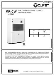
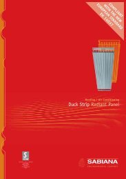
DIMENSIONAL DRAWING<br />
4<br />
C<br />
3<br />
800<br />
5 8<br />
200<br />
6<br />
N<br />
E<br />
F<br />
2<br />
H<br />
B<br />
H<br />
A<br />
G<br />
1<br />
I<br />
200<br />
(1) COMPRESSOR<br />
(2) LIQUID FITTINGS<br />
(3) SUCTION LINE CONNECTIONS<br />
(4) ELECTRICAL PANEL<br />
(5) HELICAL FANS<br />
(6) POWER INPUT<br />
(7) EXTERNAL EXCHANGER<br />
(8) ACCESS TO THE ELECTRICAL PANEL<br />
200<br />
7<br />
BT04G011GB-00<br />
Size <strong>81</strong> 91 101 121<br />
A mm 1373 1373 1573 1573<br />
B mm 557 557 557 557<br />
C mm 1225 1225 1225 1225<br />
E mm 80 80 80 80<br />
F mm 75 75 75 75<br />
G mm 508 508 508 508<br />
H mm 42 42 42 42<br />
I mm 1343 1343 1543 1543<br />
N mm 125 125 125 125<br />
10
SPLIT SYSTEM<br />
<strong>81</strong> - <strong>242</strong><br />
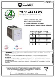
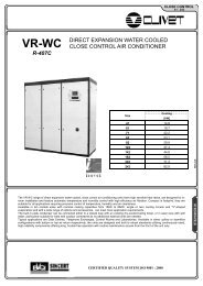
DIMENSIONAL DRAWING<br />
(1) COMPRESSOR<br />
(4) ELECTRICAL PANEL<br />
(2) LIQUID LINE CONNECTION C1<br />
(2) LIQUID LINE CONNECTION C2<br />
(3) SUCTION LINE CONNECTION C1<br />
(3) SUCTION LINE CONNECTION C2<br />
(5) HELICAL FANS<br />
(6) POWER INPUT<br />
(7) EXTERNAL EXCHANGER<br />
(8) ACCESS TO THE ELECTRICAL PANEL<br />
Size 142 162 182 202 <strong>242</strong><br />
A mm 1563 1563 1563 2098 2098<br />
B mm 1107 1107 1107 1107 1107<br />
C mm 1570 1570 1570 1570 1570<br />
D mm 128 128 128 128 128<br />
E mm 130 130 130 130 130<br />
F mm 75 75 75 75 75<br />
G mm 1058 1058 1058 1058 1058<br />
H mm 42 42 42 42 42<br />
I mm 1077 1077 1077 1612 1612<br />
L mm 900 900 900 900 900<br />
O mm 153 153 153 153 153<br />
CLIVET S.P.A.<br />
Feltre (BL) - ITALY<br />
Tel. +39 0439 3131<br />
Fax +39 0439 313300<br />
info@clivet.it<br />
CLIVET ESPAÑA S.A.<br />
Madrid - SPAIN<br />
Tel. +34 91 6852344<br />
Fax +34 91 6852353<br />
info@clivet.es<br />
CLIVET UK LTD<br />
Sevenoaks (Kent) - U.K.<br />
Tel. +44 (0) 1732 464141<br />
Fax +44 (0) 1732 741575<br />
info@clivet-uk.co.uk<br />
CLIVET NEDERLAND B.V.<br />
Amersfoort - Netherlands<br />
Tel. +31 (0) 33 7503420<br />
Fax +31 (0) 33 7503424<br />
info@clivet.nl<br />
CLIVET TUNISIE S.a.r.l.<br />
Sidi Rezig - TUNISIE<br />
Tel. +216 71 426 285<br />
Fax +216 71 429 285<br />
clivet.tunisie@planet.tn<br />
The data contained in this bulletin is not binding and may be changed by the manufacturer without prior notice. All reproduction, even partial, is prohibited.<br />
© Copyright - CLIVET S.p.A. - Feltre (BL) - Italy