- Page 1 and 2:
European Laboratory for Structural
- Page 3 and 4:
Proceedings of a Course on: Numeric
- Page 5:
Programme of the Course 1. Introduc
- Page 10 and 11:
Credits & Acknowledgments • Struc
- Page 12 and 13:
Introductory Example (4) 7 Applicat
- Page 14 and 15:
x Computational Framework • Gover
- Page 16 and 17:
n+ 1 n ∆t n n+ 1 u = u + ( u + u
- Page 18 and 19:
Scheme start-up and marching (2)
- Page 20 and 21:
Stress Update • To solve the equi
- Page 22 and 23:
Geometric non-linearities (3) Set u
- Page 24 and 25:
Essential Boundary Conditions Essen
- Page 26 and 27:
Exercise 0 - Ideal ballistics • M
- Page 28 and 29:
Exercise 0 - Ideal ballistics (5)
- Page 30 and 31:
Exercise 1 - Suspended mass (3) •
- Page 32 and 33:
Exercise 1 - Suspended mass (7) •
- Page 34 and 35:
Exercise 2 - Wave propagation (4)
- Page 36 and 37:
Exercise 3 - Impact on Cooling Towe
- Page 41 and 42:
TITLE: PMAT04: motion of projectile
- Page 43 and 44:
sinon; tra2 = tra2 et ele; finsi; f
- Page 45 and 46:
Some results: horizontal and vertic
- Page 47:
PMAT01E This test is similar to PMA
- Page 50 and 51:
Hence: 11 −8 ES 2× 10 ⋅ 2.5×
- Page 52 and 53:
The stress history is: Note that th
- Page 54 and 55:
Analytical TEST11 Same as TEST01 bu
- Page 56 and 57:
Comparison of natural vs. engineeri
- Page 58 and 59:
The total external forces at the tw
- Page 61 and 62:
TEST13 Same as TEST01 but uses a 10
- Page 63 and 64:
The mass returns at the initial pos
- Page 65 and 66:
TEST22 To verify the independence o
- Page 67 and 68:
Linear dynamic analysis Consider th
- Page 69 and 70:
• The two waves f and g propagate
- Page 71 and 72:
Analytical solution For the bar imp
- Page 73 and 74:
Note that we have also put the Pois
- Page 75 and 76:
BARI08 We study the effect of the t
- Page 77 and 78:
ENDPLAY *==========================
- Page 79:
BARI10 Same as BARI09 but compares
- Page 82 and 83:
The system is initially at rest, an
- Page 84 and 85:
CAST MESH TRID NONL LAGR $ $ Dimens
- Page 86:
Final deformation (with superposed
- Page 90 and 91:
Detailed Contents • Modeling the
- Page 92 and 93:
Modeling the fluid domain • The f
- Page 94 and 95:
Euler equations (3) • For a compr
- Page 96 and 97:
Time integration Each time incremen
- Page 98 and 99:
Time integration (5) 10. Account fo
- Page 100 and 101:
Euler Equations (FV) • They are w
- Page 102 and 103:
Mesh rezoning - motivations • Rez
- Page 104 and 105:
Giuliani’s automatic rezoning •
- Page 106 and 107:
• Analytical solution (self-simil
- Page 108 and 109:
Shock tube (6) • Influence of pse
- Page 110 and 111:
Exercise 2 - Explosion in air-fille
- Page 112 and 113:
Exercise 3 - Bubble expansion in a
- Page 114 and 115:
Exercise 4 - External blast on two
- Page 119 and 120:
Geometric data: The calculation is
- Page 121 and 122:
SHOC01 Eulerian, “average” pseu
- Page 123 and 124:
COUR 7 'ro_a' ECRO COMP 2 ELEM LECT
- Page 125 and 126:
Analytical Conclusion: the pseudo-v
- Page 127 and 128:
SHOC13 Eulerian, very low pseudo-vi
- Page 129 and 130:
Analytical General conclusions: •
- Page 131 and 132:
The inverse path is not so straight
- Page 133 and 134:
The input files (mesh generation by
- Page 135 and 136:
Geometric data: The calculation is
- Page 137 and 138:
COUR 1 'dx_4' DEPL COMP 1 NOEU LECT
- Page 139 and 140:
TANK02 Eulerian solution: the whole
- Page 141:
The final pressure distribution is:
- Page 144 and 145:
TUBE06 Lagrangian solution: the who
- Page 146 and 147:
And the final velocity distribution
- Page 148 and 149:
The computed displacements are: To
- Page 150 and 151:
43 30 30 43 44 31 31 44 45 32 32 45
- Page 153 and 154:
Geometric data: External blast in a
- Page 155 and 156:
abs4 = dall (p4 d 28 p4u) (p4u d 40
- Page 157 and 158:
Geometric data: Internal blast in a
- Page 159 and 160:
air = air1 ET air2 ET air3 ET air4
- Page 161 and 162:
COURBE 8 'P e_p12' ECROU COMP 1 lec
- Page 163 and 164:
3D axisymmetric simulation: JWLS3G
- Page 165 and 166:
point lect 1 term elem lect 1 term
- Page 169 and 170:
Universitat Politècnica de Catalun
- Page 171 and 172:
• Motivation Detailed Contents
- Page 173 and 174:
FSI Classification FSI for compress
- Page 175 and 176:
The 2-D plane case (2) Use geometri
- Page 177 and 178:
Classification of FSI algorithms
- Page 179 and 180:
The FSA algorithm (4) The case of s
- Page 181 and 182:
The FSCR algorithm Combination of F
- Page 183 and 184:
Application to Finite Volumes (3) 2
- Page 185 and 186:
Exercise 2 - Explosions in simple d
- Page 187 and 188:
Exercise/Example 3 - Wave propagati
- Page 189 and 190:
Exercise/Example 4 - CONT problem (
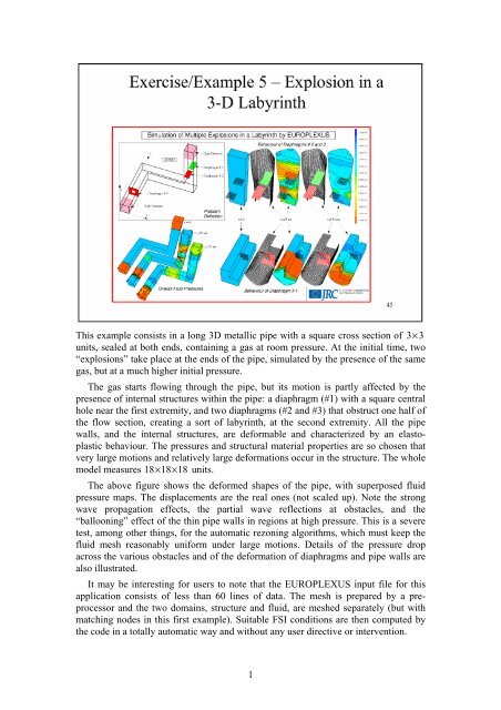
- Page 191 and 192: Exercise/Example 5 - Explosion in a
- Page 193 and 194: Exercise/Example 6 : Woodward-Colel
- Page 195 and 196: Geometry: Exercise/Example 8 Steam
- Page 197 and 198: Exercise/Example 9 Explosion in Sec
- Page 199 and 200: Exercise/Example 9 Explosion in Sec
- Page 201 and 202: Boundary Condition Elements: CLxx (
- Page 203 and 204: Exercise/Example 11 - Perforated Pl
- Page 205 and 206: Exercise/Example 12 - Sloshing (3)
- Page 207 and 208: Exercise/Example 12 - Sloshing (7)
- Page 209: Exercise/Example 12 - Sloshing (11)
- Page 214 and 215: DIME PT3L 23 PT2L 143 FL24 145 ED01
- Page 216 and 217: The final pressure field in the flu
- Page 218 and 219: ALE solution with FSA: it is not po
- Page 220 and 221: 120 119 138 139 121 120 139 140 122
- Page 222 and 223: and the final velocity field: The s
- Page 224 and 225: The final velocities: The final liq
- Page 226 and 227: *----------------------------------
- Page 228 and 229: TWIS07 We study the phenomenon by a
- Page 231 and 232: This is a well-known reactor safety
- Page 233 and 234: 1.53330E+00 1.32310E+01 1.15000E+00
- Page 235 and 236: 200 199 239 240 200 200 200 240 241
- Page 237 and 238: *----------------------------------
- Page 239 and 240: The final fluid pressures: CONT02 T
- Page 241: The final fluid velocities: The fin
- Page 245 and 246: GEOM FL38 flui Q4GS stru TERM COMP
- Page 248 and 249: Detail of first diaphragm: Detail o
- Page 250 and 251: BOUNDARY CONDITIONS: The step is en
- Page 252 and 253: The EUROPLEXUS input file reads: WO
- Page 254 and 255: WOCO3D The mesh generation file (K2
- Page 256 and 257: * RESU ALIC GARD PSCR * SORT GRAP *
- Page 258 and 259: PT3L 16389 PT6L 504 NBLE 16389 NALE
- Page 260 and 261: Final pressure distribution: 4
- Page 262 and 263: BOUNDARY CONDITIONS: The vessel is
- Page 264 and 265: as01=daller c1 c2 c3 c4 plan; * c1=
- Page 266 and 267: *trac oeil cach fluidstr; *opti don
- Page 268 and 269: cam3=cam31 et cam32; camb=cam1 et c
- Page 270 and 271: log 1 dtml REZO GAM0 0.5 FLMP EPS1
- Page 272 and 273: Final structure deformation: Final
- Page 274 and 275: LOADING: The event is initiated by
- Page 276 and 277: FLUT RO .242777373 EINT 6.865E5 GAM
- Page 278 and 279: Final structure velocities: 6
- Page 280 and 281: RESULTS: A paper by Bermudez and Ro
- Page 282 and 283: The applied displacement and the co
- Page 284 and 285: PROBLEM: A rigid tank with a deform
- Page 286: The EUROPLEXUS input file reads: GR
- Page 289 and 290: PROBLEM: A rigid tank with rigid or
- Page 291 and 292: COMP EPAI 0.005 LECT 101 102 103 10
- Page 293 and 294:
Numerical Solution (flexible bottom
- Page 295 and 296:
! VARI DEPL VITE ECRO ! fich alic t
- Page 297 and 298:
The final pressures in the rigid an
- Page 299 and 300:
LOADING: A constant gravity in the
- Page 301 and 302:
Some results: intermediate and fina
- Page 305 and 306:
Universitat Politècnica de Catalun
- Page 307 and 308:
ALE description of structures (2)
- Page 309 and 310:
Example 1 - Taylor bar impact (3) B
- Page 311 and 312:
Example 3 - Coining (3) Influence o
- Page 313 and 314:
• Tentative classification: Non-c
- Page 315 and 316:
Example 4 - Explosion in a 2D box (
- Page 317 and 318:
Example 6 - LOCA in the HDR (2) A -
- Page 319 and 320:
Examples of “Slow” Transient Co
- Page 321 and 322:
Examples of Fast Transient Impact
- Page 323 and 324:
Components of Contact-Impact Method
- Page 325 and 326:
Shortcomings • Slender or distort
- Page 327 and 328:
Example - Bar impact • (See Part
- Page 329 and 330:
Example 7b - Indentation (2) • 2D
- Page 331 and 332:
Example 7b - Indentation (6) • 3D
- Page 333 and 334:
Smoothed Particles Hydrodynamics (C
- Page 335 and 336:
SPH Formulation (2) • Basic idea:
- Page 337 and 338:
SPH impact [Courtesy of Samtech/Son
- Page 339 and 340:
PRGL01: Example 8 - SPH impacts (Co
- Page 341 and 342:
Spectral Elements • Motivation: l
- Page 343 and 344:
Spectral Elements (5) Convergence p
- Page 345 and 346:
Example 9 - Closed FE/SE interface
- Page 347 and 348:
Example 11 - Cylindrical valley 85
- Page 349 and 350:
Performance Optimization • All ex
- Page 351 and 352:
Time Step Partitioning (4) • Intr
- Page 353 and 354:
Time Step Partitioning (8) • Acti
- Page 355 and 356:
Treatment of links in partitioning
- Page 357 and 358:
Example 12a - Taylor bar impact rev
- Page 359 and 360:
Coupling at the Interfaces • Two
- Page 361 and 362:
Coupling at the Interfaces (5) MU T
- Page 363 and 364:
Coupling at the Interfaces (9) Time
- Page 365 and 366:
Multiple scales in time (3) • Exp
- Page 367 and 368:
Multiple scales in space • Furthe
- Page 369 and 370:
Multiple scales in frequency • So
- Page 371 and 372:
Example: power plant 133 Example: p
- Page 373 and 374:
Example: aircraft (3) Thanks to CPU
- Page 375 and 376:
Example 14 - Domains in 3D • Thic
- Page 377:
Example 15 - Bar Impact Revisited (
- Page 382 and 383:
* mesh=stru et symax et viti et lil
- Page 384 and 385:
The displacements are: 4
- Page 386 and 387:
c2=p1 d 8 p2; c3=p2 d 20 p3; c4=p3
- Page 388 and 389:
The resulting final deformed mesh w
- Page 390 and 391:
TERM *-----------------------------
- Page 393 and 394:
Geometric data and materials: The b
- Page 395 and 396:
BET0 1 KINT 0 AHGF 0 CL 0.5 CQ 2.56
- Page 397 and 398:
INFS02 We use a twice finer fluid m
- Page 399 and 400:
FREQ 1 GOTR LOOP 60 OFFS FICH AVI C
- Page 401 and 402:
Problem description: This example i
- Page 403 and 404:
*----------------------------------
- Page 405:
The final velocities: The final for
- Page 408 and 409:
*----------------------------------
- Page 410 and 411:
The final deformed mesh is: The fin
- Page 412 and 413:
pc = 4.5 -1 -1.5; pd = 5.5 -1 -1.5;
- Page 414 and 415:
The initial configuration (with par
- Page 417 and 418:
TITLE: Indentation problem. PROBLEM
- Page 419 and 420:
cp = p0 d 10 p13; elim tol (piece e
- Page 421 and 422:
The final velocities: The final dis
- Page 423 and 424:
The input file is: INDE - 13 ECHO !
- Page 425 and 426:
The final displacement norm: The fi
- Page 427 and 428:
elim tol (piece et cp); c_p = piece
- Page 429 and 430:
The final deformed shape is: 13
- Page 431 and 432:
Numerical Solutions PRGL01 Simplifi
- Page 433 and 434:
FOV 2.48819E+01 SCEN GEOM NAVI FREE
- Page 435 and 436:
ROMA01 Final plastic streen in the
- Page 437 and 438:
SONA01 7
- Page 439:
Final density in the projectile: Fi
- Page 442 and 443:
opti echo 0; opti donn 'D:\Users\Fo
- Page 444 and 445:
* opti dime 2 elem qua4; p0 = 0 0;
- Page 446 and 447:
The final X-displacement in the hyb
- Page 448 and 449:
* opti dime 2 elem qua4; opti titr
- Page 450 and 451:
VALLPS This calculation assumes a p
- Page 452 and 453:
The receiver signal in the coupled
- Page 455 and 456:
Problem description: This example r
- Page 457 and 458:
CALC TINI 0. TFIN 40.E-3 *=========
- Page 459 and 460:
REPETER BCL2 (2); REPETER BCL3 (2);
- Page 461 and 462:
*----------------------------------
- Page 463 and 464:
The tip displacement in the referen
- Page 465 and 466:
Problem description: This example r
- Page 467 and 468:
LOG 1 DPSD *-----------------------
- Page 469 and 470:
TRAC CACH OEIL2 ZONE1; TRAC CACH OE
- Page 471 and 472:
The tip displacement in the referen
- Page 473 and 474:
Problem description: This example r
- Page 475 and 476:
$ INIT VITE 2 -227. LECT VITI TERM
- Page 477 and 478:
* AXTE 1000.0 'Time [ms]' * COUR 1
- Page 479 and 480:
sq41=sq41 coul 'TURQ'; sq42=sq42 co
- Page 481 and 482:
The displacements in the case with
- Page 485 and 486:
European Commission DG Joint Resear