The LINOS Laser Modulators and Pockels Cells - Qioptiq Q-Shop
The LINOS Laser Modulators and Pockels Cells - Qioptiq Q-Shop
The LINOS Laser Modulators and Pockels Cells - Qioptiq Q-Shop

You also want an ePaper? Increase the reach of your titles
YUMPU automatically turns print PDFs into web optimized ePapers that Google loves.
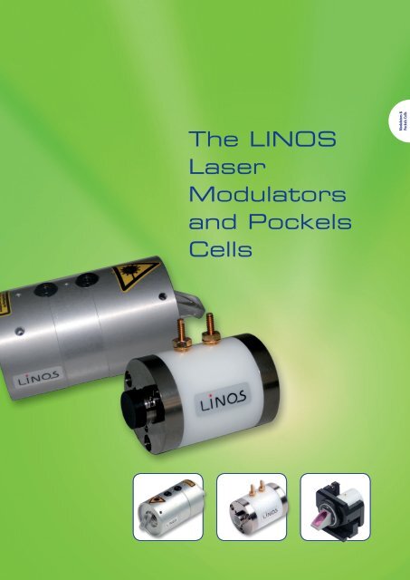
<strong>The</strong> <strong>LINOS</strong><br />
<strong>Laser</strong><br />
<strong>Modulators</strong><br />
<strong>and</strong> <strong>Pockels</strong><br />
<strong>Cells</strong><br />
<strong>Modulators</strong> &<br />
<strong>Pockels</strong> <strong>Cells</strong>
<strong>The</strong> <strong>LINOS</strong> <strong>Laser</strong> <strong>Modulators</strong><br />
<strong>and</strong> <strong>Pockels</strong> <strong>Cells</strong><br />
Electro-optical modulators are divided into<br />
modulators (for applications outside of laser<br />
cavity) <strong>and</strong> <strong>Pockels</strong> cells (for applications<br />
within laser cavity) on the following pages.<br />
You can choose from a large selection of crystals<br />
for a variety of applications, apertures<br />
<strong>and</strong> laser outputs, covering the entire wavelength<br />
range from 250 nm to 3 µm. <strong>The</strong> consistently<br />
high <strong>LINOS</strong> quality <strong>and</strong> incomparable<br />
value of our products is assured by a<br />
combination of our many years of experience,<br />
an intelligent design, modern engineering<br />
with computer simulations <strong>and</strong> sophisticated<br />
processing.<br />
In addition we offer a broad range of fast<br />
<strong>and</strong> high-performance high-voltage drivers.<br />
For details, please contact our staff from the<br />
customer service.<br />
<strong>LINOS</strong> quality criteria:<br />
• Best possible extinction ratio<br />
for each crystal<br />
• High transmission<br />
• Patented isolation system minimizes<br />
piezoelectric oscillation for<br />
exceptionally precise switching<br />
operations (optional)<br />
!<br />
Special features:<br />
On request we can modify any<br />
product for wavelengths in the<br />
250 nm to 3 µm range, even for<br />
one-time orders. .<br />
Ideal areas of application:<br />
Phase <strong>and</strong> intensity modulation;<br />
Q-switching; pulse picking.<br />
More information:<br />
Contact us to receive our comprehensive<br />
new brochure, "Crystal<br />
Technology," by mail, or download<br />
it from: www.linos.com/ct<br />
646<br />
US-Phone +1 585 223-2370 UK-Phone +44 2380 744 500
<strong>Laser</strong> <strong>Modulators</strong> <strong>and</strong> <strong>Pockels</strong> <strong>Cells</strong><br />
<strong>Laser</strong> <strong>Modulators</strong> ___________________________<br />
Introduction 648<br />
Technincal Overview 648<br />
Phase Modulator PM 25 650<br />
Phase Modulator PM-C-BB 651<br />
<strong>Laser</strong> <strong>Modulators</strong> LM 13 652<br />
<strong>Laser</strong> <strong>Modulators</strong> LM 0202 654<br />
Digital Pulse Amplifier LIV 20 656<br />
Analog Amplifier LAV 400 657<br />
<strong>Pockels</strong> <strong>Cells</strong> ________________________________<br />
Technical Information 658<br />
Product Overview 660<br />
KD*P <strong>Pockels</strong> <strong>Cells</strong> LM Series 661<br />
KD*P <strong>Pockels</strong> <strong>Cells</strong> MIQS 8 Series 662<br />
KD*P-<strong>Pockels</strong> <strong>Cells</strong> CPC Series 663<br />
KD*P <strong>Pockels</strong> <strong>Cells</strong> CIQS Series 664<br />
KD*P <strong>Pockels</strong> <strong>Cells</strong> SPC 4 Series 665<br />
KD*P Double <strong>Pockels</strong> <strong>Cells</strong> DPZ Series 666<br />
KD*P Brewster <strong>Pockels</strong> Cell BPC 8 667<br />
LiNbO 3<br />
<strong>Pockels</strong> <strong>Cells</strong> 668<br />
BBO <strong>Pockels</strong> <strong>Cells</strong> BBPC Series 669<br />
BBO Double <strong>Pockels</strong> <strong>Cells</strong> DBBPC Series 670<br />
RTPC <strong>Pockels</strong> <strong>Cells</strong> Series 671<br />
<strong>Pockels</strong> <strong>Cells</strong> Positioner 672<br />
Germany-Phone: +49 (0) 551/ 6935-0 France-Phone: +33 - 47 25 20 420<br />
647
Isolators<br />
<strong>Laser</strong> <strong>Modulators</strong>, Introduction<br />
Technincal Overview<br />
Electro-optical crystals are characterized<br />
by their ability to change optical path<br />
length in function of an applied<br />
external voltage. This change depends<br />
on the direction of polarization of the<br />
irradiated light. At λ/2 voltage, the path<br />
length difference of orthogonally<br />
polarized beams is just half of the<br />
wavelength. With a suitable orientation<br />
of the crystals, the polarization direction<br />
of the irradiated light is rotated 90°: in<br />
this state the light is extinguished by a<br />
polarizer. Varying the applied voltage<br />
allows quick modulation of the laser<br />
beam intensity. <strong>The</strong> performance of an<br />
electro-optic modulator can be understood<br />
very simply as that of a retardation<br />
plate with electrically adjustable<br />
retardation.<br />
Series LM 0202 <strong>Modulators</strong> use the<br />
transverse electro-optical effect: the<br />
direction of the light beam <strong>and</strong> electric<br />
field are orthogonal. In this configuration,<br />
long crystals with a small cross<br />
section have a low half wave voltage<br />
Since most of the electro-optical crystals<br />
operate with a strong background of<br />
natural birefringence, a compen sation<br />
scheme is used. Each modulator in the<br />
LM 0202 series has four crystals as a<br />
matched ensemble. <strong>The</strong>se crystals are<br />
fabricated with deviations in length less<br />
than 100 nm. <strong>The</strong> crystals are operated<br />
optically in series <strong>and</strong> electrically parallel.<br />
<strong>The</strong> crystal orientation of the LM 0202<br />
<strong>and</strong> LM 0202P modulators has been<br />
optimized to minimize the retar da tion<br />
caused by natural birefringence. Just as<br />
in an ordina ry retardation plate, the<br />
polarization of the laser beam has to be<br />
adjusted at 45° to the optical axis in<br />
order to achieve a proper 90° rotation.<br />
If the laser beam is polarized in the<br />
direction of the optical axis, no polarization<br />
rotation, but pure phase retardation<br />
will occur. In principle this allows the user<br />
to operate the LM 0202 modulator as a<br />
phase modulator. In this configu ration,<br />
optimized for minimum background<br />
retar da tion, two of the four crystals are<br />
electro-optically active for phase<br />
modulation. A special model, LM 0202<br />
PHAS, is available with a crystal configuration<br />
that uses all four crystals for phase<br />
modulation.<br />
<strong>The</strong> PM 25 Phase Modulator, is a<br />
Brewster modulator of high optical<br />
quality <strong>and</strong> should be used for loss<br />
sensitive applications, especially intracavity<br />
modulation. Mounting the modulator<br />
in the resonator is simple, as there is<br />
no beam deviation or displacement.<br />
All modulators use electro-optical crystals<br />
that possess strong natural birefringence.<br />
<strong>The</strong> crystals are used in order of compensation<br />
<strong>and</strong> there is no beam deviation or<br />
displacement.<br />
Electro-optic modulators generally<br />
require linearly polarized laser light. If<br />
the laser light is not sufficiently polarized<br />
by itself, an additional polarizer must be<br />
used.<br />
<strong>The</strong> Intensity Modulator LM 0202 P has<br />
an integrated polarizer that is used as an<br />
analyzer.<br />
<strong>The</strong> modulator voltage input plugs are<br />
isolated from the housing <strong>and</strong> directly<br />
connected to the crystals. A change of<br />
the laser intensity can be observed when<br />
the applied voltage is changed. By<br />
subsequently adjusting voltage <strong>and</strong><br />
rotation, an extinction better than 250:1<br />
can be achieved. Selected models with<br />
better extinction ratios are available on<br />
request.<br />
Operating an electro-optical modulator<br />
between crossed, or parallel, polarizers<br />
yields an intensity variation given by the<br />
following formula:<br />
I = I o<br />
· sin 2 (U/U λ/2<br />
· π/2)<br />
U λ/2<br />
- half wave voltage<br />
I o<br />
- input intensity<br />
U - signal voltage<br />
It has been assumed that the appropriate<br />
offset voltage has been applied for<br />
maximum extinction. <strong>The</strong> offset voltage<br />
causes a shift of the intensity curve over<br />
the voltage. <strong>The</strong> half wave voltage is<br />
proportionally to the wavelength λ, to<br />
the crystal thickness d <strong>and</strong> in reverse<br />
proportional to the crystal length l:<br />
Here n 0<br />
is the refractive index of the<br />
ordinary beam <strong>and</strong> r 63<br />
the electro-optical<br />
coefficient of the crystal.<br />
In many cases it is advantageous to select<br />
an offset voltage such that the first order<br />
intensity varies linearly with voltage. This<br />
is achieved by setting the offset voltage<br />
to the value required for maximum<br />
extinction minus<br />
½ · U λ/2<br />
.<br />
<strong>The</strong> LM 0202 series modulators are<br />
hermetically sealed. <strong>The</strong>y can be<br />
operated at pressures from 100 mbar to<br />
1500 mbar <strong>and</strong> at a temperature range<br />
between 0 °C to 50 °C.<br />
St<strong>and</strong>ard models are designed for<br />
horizontal operation. <strong>Modulators</strong> for<br />
vertical use are available by request. <strong>The</strong><br />
modulator windows are easily cleaned<br />
with a mild organic solvent.<br />
648<br />
US-Phone +1 585 223-2370 UK-Phone +44 2380 744 500
<strong>Laser</strong> <strong>Modulators</strong> <strong>and</strong> <strong>Pockels</strong> <strong>Cells</strong><br />
Applications<br />
Selection Criteria<br />
<strong>The</strong> series LM 0202 or LM 13 electrooptical<br />
modulators are typically used<br />
when intensity, power, phase or polarization<br />
state modulation is required. <strong>The</strong><br />
devices are ideal for continuous or pulsed<br />
laser applications. St<strong>and</strong>ard models, in<br />
many configurations, are available for<br />
wavelength ranges or for definite<br />
wavelengths between 250 to 1100 nm<br />
<strong>and</strong> operation up to 3000 nm is possible<br />
with special crystals.<br />
<strong>The</strong> modulators are typically used with<br />
diode lasers, solid state lasers, ion lasers,<br />
gas lasers or white light lasers.<br />
<strong>The</strong> required wavelength <strong>and</strong> aperture<br />
are determined based on the existing<br />
laser system. Very high laser power, in<br />
the multiwatt range, requires a large<br />
aperture. <strong>Laser</strong> lines in the short wave<br />
spectral region can work problem free<br />
with modulators having low electrooptical<br />
sensi tivity: this gives rise to<br />
advantages in b<strong>and</strong>width <strong>and</strong> size. A<br />
Brewster modu lator of high optical<br />
quality should be used for loss sensitive<br />
applications, especially intra cavity<br />
modulation.<br />
<strong>Modulators</strong> &<br />
<strong>Pockels</strong> <strong>Cells</strong><br />
<strong>The</strong>se devices are being used in the fields<br />
of reprography, stereo lithography, laser<br />
projection, optical storage, printing,<br />
research <strong>and</strong> development <strong>and</strong> communication<br />
engineering in the laser<br />
industry.<br />
<strong>The</strong> PM 25 <strong>and</strong> PM-CBB series are<br />
typically used for fast intra-cavity phase<br />
modulation. <strong>The</strong>refore very fast control<br />
loops, with high feedback gain for<br />
frequency <strong>and</strong> phase stabili zation, can be<br />
constructed for precision lasers.<br />
Germany-Phone: +49 (0) 551/ 6935-0 France-Phone: +33 - 47 25 20 420<br />
649
Isolators<br />
Phase Modulator PM 25<br />
• Two crystals at Brewster angle<br />
in orderof compensation<br />
• With Brewster windows<br />
• Very high transmission<br />
• Connectors: 4 mm banana plugs<br />
• Different versions for wavelength<br />
ranges between 250 <strong>and</strong> 1100 nm<br />
• Please specify the wavelength or<br />
wavelength range <strong>and</strong> laser<br />
parameters when ordering.<br />
• Wavefront distortion < λ/10<br />
at 633nm<br />
• B<strong>and</strong>width (3 dB) 100 MHz<br />
• Capacitance 30 pF<br />
• Max. continuous voltage 1500 V<br />
• Operating temperature 10 - 45 °C<br />
• Weight approx. 500 g<br />
Phase Modulator PM 25<br />
Product<br />
Wavelengths<br />
(nm)<br />
Power capability (W)<br />
Transmission<br />
(%)<br />
Aperture<br />
(mm)<br />
λ/10-voltage at<br />
633 nm(V)<br />
Order-No<br />
PMADP 400-650 100 W (> 400 nm), 10 W (< 400nm) > 98 5 x 5 200 ±10 % 84 50 2030 000<br />
PMKD*P 250-1100 100 W (> 400 nm), 10 W (< 400nm) > 98 5 x 5 200 ±10 % 84 50 2031 000<br />
650<br />
US-Phone +1 585 223-2370 UK-Phone +44 2380 744 500
<strong>Laser</strong> <strong>Modulators</strong> <strong>and</strong> <strong>Pockels</strong> <strong>Cells</strong><br />
Phase Modulator PM-C-BB<br />
• Brewster-cut MgO-LiNbO3 crystal<br />
• High photorefractive damage<br />
threshold<br />
• Broad wavelength range<br />
450 – 3000nm<br />
• High transmission<br />
• Compact design<br />
• Small residual amplitude modulation<br />
• Connector: 1 x SMA<br />
• Built-in active temperature<br />
stabilization (< 10 mK) on request<br />
• Wavefront distortion < λ/4 at 633 nm<br />
• B<strong>and</strong>width DC – 500 MHz<br />
(> 10 MHzresonance-free)<br />
<strong>Modulators</strong> &<br />
<strong>Pockels</strong> <strong>Cells</strong><br />
Phase Modulator PM-C-BB<br />
ItemTiltle<br />
Wavelength<br />
(nm)<br />
Power capability Transmis sion 2) Aperture<br />
at 1064nm 1) (ClearApertur)<br />
λ/10-Voltage at<br />
1064 nm<br />
Order-No<br />
PM-C-BB 450-3000 > 100 W / mm 2 > 98 % 1.9 mm (1.5 mm) 100 V ± 10 % 84 51 2090 0006<br />
1) CW operation, depends on wavelength<br />
2) excluded: LiNbO3 absorption at 2.82 - 2.84 µm<br />
Germany-Phone: +49 (0) 551/ 6935-0 France-Phone: +33 - 47 25 20 420<br />
651
Isolators<br />
<strong>Laser</strong> <strong>Modulators</strong> LM 13<br />
• Different versions: Universalmodulator,<br />
Intensity modulator (P)with thin<br />
film polarizer, Phasemodulator (PHAS)<br />
• With 2 crystals in order of<br />
compensation<br />
• Connectors: 4 mm banana plugs<br />
• Different versions for wavelength<br />
ranges between 250 <strong>and</strong> 1100 nm<br />
• Extinction 1) > 250 : 1 (VIS, IR)<br />
or > 100 :1 (UV)<br />
• Wavefront distortion < λ /4 at 633 nm<br />
• B<strong>and</strong>width (3 dB) 100 MHz<br />
• Capacitance 46 pF<br />
• Max. continuous voltage 800 V<br />
• Operating temperature 10 - 45 °C<br />
• Weight approx. 500 g<br />
• 1) Extinction: measured at continuous<br />
wave between crossed polarizers.<br />
• Please specify the wavelength or<br />
wavelength range <strong>and</strong> laser<br />
parameters when ordering.<br />
LM 13 (P) (PHAS)<br />
St<strong>and</strong>ardPlus<br />
<strong>Modulators</strong> series LM 13 are also available with the crystal LiTaO 3<br />
- as<br />
universal or intensity modulator.<br />
LM 13 UV KD*P<br />
Product<br />
Wavelengths<br />
(nm)<br />
Power capability<br />
(W)<br />
Transmission 2) <br />
(%)<br />
Aperture<br />
(mm)<br />
λ/2-voltage at 355 nm<br />
(V)<br />
Order-No<br />
LM 13 250-310 0.1 > 91 / 88 Ø 1.5 240 ± 10 % 84 50 2020 020<br />
LM 13 250-310 0.1 > 91 / 88 Ø 3.5 390 ± 10 % 84 50 2021 020<br />
LM 13 300-390 1.0 > 95 / 92 Ø 1.5 240 ± 10 % 84 50 2023 019<br />
LM 13 300-390 1.0 > 95 / 92 Ø 3.5 390 ± 10 % 84 50 2024 019<br />
LM 13 P 250-310 0.1 > 91 / 88 Ø 1.5 240 ± 10 % 84 50 2026 020<br />
LM 13 P 250-310 0.1 > 91 / 88 Ø 3.5 390 ± 10 % 84 50 2027 020<br />
LM 13 P 300-390 1.0 > 95 / 92 Ø 1.5 240 ± 10 % 84 50 2029 019<br />
LM 13 P 300-390 1.0 > 95 / 92 Ø 3.5 390 ± 10 % 84 50 2030 019<br />
LM 13PHAS 250-310 0.1 > 91 / 88 Ø 1.5 240 ± 10 % 84 50 2032 020<br />
LM 13PHAS 250-310 0.1 > 91 / 88 Ø 3.5 390 ± 10 % 84 50 2033 020<br />
LM 13PHAS 300-390 1.0 > 95 / 92 Ø 1.5 240 ± 10 % 84 50 2035 019<br />
LM 13PHAS 300-390 1.0 > 95 / 92 Ø 3.5 390 ± 10 % 84 50 2036 019<br />
2) Transmission: measured without / with polarizing beamsplitter cube.<br />
652<br />
US-Phone +1 585 223-2370 UK-Phone +44 2380 744 500
<strong>Laser</strong> <strong>Modulators</strong> <strong>and</strong> <strong>Pockels</strong> <strong>Cells</strong><br />
LM 13 VIS KD*P<br />
Product<br />
Wavelengths<br />
(nm)<br />
Power capability<br />
(W)<br />
Transmission 2) <br />
(%)<br />
Aperture<br />
(mm)<br />
λ/2-voltage at 633 nm<br />
(V)<br />
Order-No<br />
LM 13 400-850 0.1 > 98 / 95 3 x 3 420 ± 10 % 84 50 2020 000<br />
LM 13 400-850 0.1 > 98 / 95 5 x 5 700 ± 10 % 84 50 2021 000<br />
LM 13 400-850 5.0 > 95 / 92 3 x 3 420 ± 10 % 84 50 2023 000<br />
LM 13 400-850 5.0 > 95 / 92 5 x 5 700 ± 10 % 84 50 2024 000<br />
LM 13 P 400-850 0.1 > 98 / 95 3 x 3 420 ± 10 % 84 50 2026 000<br />
LM 13 P 400-850 0.1 > 98 / 95 5 x 5 700 ± 10 % 84 50 2027 000<br />
LM 13 P 400-850 5.0 > 95 / 92 3 x 3 420 ± 10 % 84 50 2029 000<br />
LM 13 P 400-850 5.0 > 95 / 92 5 x 5 700 ± 10 % 84 50 2030 010<br />
LM 13PHAS 400-850 0.1 > 98 / 95 3 x 3 420 ± 10 % 84 50 2032 000<br />
LM 13PHAS 400-850 0.1 > 98 / 95 5 x 5 700 ± 10 % 84 50 2033 000<br />
LM 13PHAS 400-850 5.0 > 95 / 92 3 x 3 420 ± 10 % 84 50 2035 000<br />
LM 13PHAS 400-850 5.0 > 95 / 92 5 x 5 700 ± 10 % 84 50 2036 000<br />
<strong>Modulators</strong> &<br />
<strong>Pockels</strong> <strong>Cells</strong><br />
2) Transmission: measured without / with polarizing beamsplitter cube.<br />
LM 13 IR KD*P<br />
Product<br />
Wavelengths<br />
(nm)<br />
Power capability<br />
(W)<br />
Transmission 2) <br />
(%)<br />
Aperture<br />
(mm)<br />
λ/2-voltage at 1064 nm<br />
(V)<br />
Order-No<br />
LM 13 650-1000 5.0 > 95 / 92 3 x 3 710 ± 10 % 84 50 2023 015<br />
LM 13 950-1100 5.0 > 94 / 91 3 x 3 710 ± 10 % 84 50 2023 016<br />
LM 13 P 650-1000 5.0 > 95 / 92 3 x 3 710 ± 10 % 84 50 2029 015<br />
LM 13 P 950-1100 5.0 > 94 / 91 3 x 3 710 ± 10 % 84 50 2029 016<br />
LM 13PHAS 650-1000 5.0 > 95 / 92 3 x 3 710 ± 10 % 84 50 2035 015<br />
LM 13PHAS 650-1000 5.0 > 95 / 92 5 x 5 1180 ± 10 % 84 50 2036 015<br />
LM 13PHAS 950-1100 5.0 > 94 / 91 3 x 3 710 ± 10 % 84 50 2035 016<br />
LM 13PHAS 950-1100 5.0 > 94 / 91 5 x 5 1180 ± 10 % 84 50 2036 016<br />
2) Transmission: measured without / with polarizing beamsplitter cube.<br />
LM 13 IR KD*P High Power<br />
Product<br />
Wavelengths<br />
(nm)<br />
Power capability<br />
(W)<br />
Transmission 2) <br />
(%)<br />
Aperture<br />
(mm)<br />
λ/2-voltage at 1064 nm<br />
(V)<br />
Order-No<br />
LM 13 700-950 10 > 94 / 91 Ø1.0 710 ± 10 % 84 50 2023 017<br />
LM 13 950-1100 20 > 93 / 90 Ø1.0 710 ± 10 % 84 50 2023 018<br />
LM 13 P 700-950 10 > 94 / 91 Ø1.0 710 ± 10 % 84 50 2029 017<br />
LM 13 P 950-1100 20 > 93 / 90 Ø1.0 710 ± 10 % 84 50 2029 018<br />
LM 13PHAS 700-950 10 > 94 / 91 Ø1.0 710 ± 10 % 84 50 2035 017<br />
LM 13PHAS 700-950 10 > 94 / 91 Ø3.0 1180 ± 10 % 84 50 2036 017<br />
LM 13PHAS 950-1100 20 > 93 / 90 Ø1.0 710 ± 10 % 84 50 2035 018<br />
LM 13PHAS 950-1100 20 > 93 / 90 Ø3.0 1180 ± 10 % 84 50 2036 018<br />
2) Transmission: measured without / with polarizing beamsplitter cube<br />
Germany-Phone: +49 (0) 551/ 6935-0 France-Phone: +33 - 47 25 20 420<br />
653
Isolators<br />
<strong>Laser</strong> <strong>Modulators</strong> LM 0202<br />
• Different versions: Universalmodulator,<br />
Intensity modulator (P)with thin<br />
film polarizer, Phasemodulator (PHAS)<br />
• With 4 crystals in order of<br />
compensation<br />
• Connectors: 4 mm banana plugs<br />
• Different versions for wavelength<br />
ranges between 250 <strong>and</strong> 1100 nm<br />
• Extinction 1) > 250 : 1 (VIS, IR) or<br />
> 100 :1 (UV)<br />
• Wavefront distortion < λ/4 at 633 nm<br />
• B<strong>and</strong>width (3 dB) 100 MHz<br />
• Capacitance 82 pF<br />
• Max. continuous voltage 800 V<br />
• Operating temperature 10 - 45 °C<br />
• Weight approx. 800 g<br />
LM 0202 (P) (PHAS)<br />
• 1) Extinction: measured at continuous<br />
wave between crossed polarizers.<br />
• Please specify the wavelength or<br />
wavelength range <strong>and</strong> laserparameters<br />
when ordering.<br />
St<strong>and</strong>ardPlus<br />
<strong>Modulators</strong> series LM 0202 are also available with the crystal LiTaO 3<br />
-<br />
as universal or intensity modulator.<br />
LM 0202 UV KD*P<br />
Product<br />
Wavelengths<br />
(nm)<br />
Power capability<br />
(W)<br />
Transmission 1) <br />
(%)<br />
Aperture <br />
(mm)<br />
λ/2-voltage (355nm)<br />
(V)<br />
Order-No<br />
LM 0202 250-310 0.1 > 88 / 85 Ø 1.5 120 ± 10 % 84 50 2040 003<br />
LM 0202 250-310 0.1 > 88 / 85 Ø 3.5 200 ± 10 % 84 50 2041 003<br />
LM 0202 300-390 1 > 93 / 90 Ø 1.5 120 ± 10 % 84 50 2049 007<br />
LM 0202 300-390 1 > 93 / 90 Ø 3.5 200 ± 10 % 84 50 2050 011<br />
LM 0202 P 250-310 0.1 > 88 / 85 Ø 1.5 120 ± 10 % 84 50 2043 003<br />
LM 0202 P 250-310 0.1 > 88 / 85 Ø 3.5 200 ± 10 % 84 50 2044 004<br />
LM 0202 P 300-390 1 > 93 / 90 Ø 1.5 120 ± 10 % 84 50 2052 013<br />
LM 0202 P 300-390 1 > 93 / 90 Ø 3.5 200 ± 10 % 84 50 2053 006<br />
LM 0202PHAS 250-310 0.1 > 88 / 85 Ø 1.5 120 ± 10 % 84 50 2046 004<br />
LM 0202PHAS 250-310 0.1 > 88 / 85 Ø 3.5 200 ± 10 % 84 50 2047 004<br />
LM 0202PHAS 300-390 1 > 93 / 90 Ø 1.5 120 ± 10 % 84 50 2055 010<br />
LM 0202PHAS 300-390 1 > 93 / 90 Ø 3.5 200 ± 10 % 84 50 2056 006<br />
1) Transmission: measured without / with polarizing beamsplitter cube<br />
LM 0202 VIS ADP<br />
Product<br />
Wavelengths<br />
(nm)<br />
Power capability<br />
(W)<br />
Transmission 1)<br />
(%)<br />
Aperture<br />
(mm)<br />
λ/2-voltage (633nm)<br />
(V)<br />
Order-No<br />
LM 0202 400-650 0.1 > 97 / 94 3 x 3 210 ± 10 % 84 50 2001 000<br />
LM 0202 400-650 0.1 > 97 / 94 5 x 5 350 ± 10 % 84 50 2002 000<br />
LM 0202 400-650 5.0 > 92 / 89 3 x 3 210 ± 10 % 84 50 2010 000<br />
LM 0202 400-650 5.0 > 92 / 89 5 x 5 350 ± 10 % 84 50 2011 000<br />
LM 0202 P 400-650 0.1 > 97 / 94 3 x 3 210 ± 10 % 84 50 2004 000<br />
LM 0202 P 400-650 0.1 > 97 / 94 5 x 5 350 ± 10 % 84 50 2005 000<br />
LM 0202 P 400-650 5.0 > 92 / 89 3 x 3 210 ± 10 % 84 50 2013 000<br />
LM 0202 P 400-650 5.0 > 92 / 89 5 x 5 350 ± 10 % 84 50 2014 000<br />
LM 0202PHAS 400-650 0.1 > 97 / 94 3 x 3 210 ± 10 % 84 50 2007 000<br />
LM 0202PHAS 400-650 0.1 > 97 / 94 5 x 5 350 ± 10 % 84 50 2008 000<br />
LM 0202PHAS 400-650 5.0 > 92 / 89 3 x 3 210 ± 10 % 84 50 2016 000<br />
LM 0202PHAS 400-650 5.0 > 92 / 89 5 x 5 350 ± 10 % 84 50 2017 000<br />
1) Transmission: measured without / with polarizing beamsplitter cube<br />
654<br />
US-Phone +1 585 223-2370 UK-Phone +44 2380 744 500
<strong>Laser</strong> <strong>Modulators</strong> <strong>and</strong> <strong>Pockels</strong> <strong>Cells</strong><br />
LM 0202 VIS KD*P<br />
Product<br />
Wavelengths<br />
(nm)<br />
Power capability<br />
(W)<br />
Transmission 1) <br />
(%)<br />
Aperture<br />
(mm)<br />
λ/2-voltage (633nm)<br />
(V)<br />
Order-No<br />
LM 0202 400-850 0.1 > 97 / 94 3 x 3 210 ± 10 % 84 50 2040 000<br />
LM 0202 400-850 0.1 > 97 / 94 5 x 5 350 ± 10 % 84 50 2041 000<br />
LM 0202 400-850 5.0 > 92 / 89 3 x 3 210 ± 10 % 84 50 2049 000<br />
LM 0202 400-850 5.0 > 92 / 89 5 x 5 350 ± 10 % 84 50 2050 005<br />
LM 0202 P 400-850 0.1 > 97 / 94 3 x 3 210 ± 10 % 84 50 2043 000<br />
LM 0202 P 400-850 0.1 > 97 / 94 5 x 5 350 ± 10 % 84 50 2044 000<br />
LM 0202 P 400-850 5.0 > 92 / 89 3 x 3 210 ± 10 % 84 50 2052 000<br />
LM 0202 P 400-850 5.0 > 92 / 89 5 x 5 350 ± 10 % 84 50 2053 000<br />
LM 0202PHAS 400-850 0.1 > 97 / 94 3 x 3 210 ± 10 % 84 50 2046 000<br />
LM 0202PHAS 400-850 0.1 > 97 / 94 5 x 5 350 ± 10 % 84 50 2047 000<br />
LM 0202PHAS 400-850 5.0 > 92 / 89 3 x 3 210 ± 10 % 84 50 2055 000<br />
LM 0202PHAS 400-850 5.0 > 92 / 89 5 x 5 350 ± 10 % 84 50 2056 000<br />
<strong>Modulators</strong> &<br />
<strong>Pockels</strong> <strong>Cells</strong><br />
1) Transmission: measured without / with polarizing beamsplitter cube<br />
LM 0202 IR KD*P<br />
Product<br />
Wavelengths<br />
(nm)<br />
Power capability<br />
(W)<br />
Transmission 1) <br />
(%)<br />
Aperture<br />
(mm)<br />
λ/2-voltage (1064nm)<br />
(V)<br />
Order-No<br />
LM 0202 650-1000 5.0 > 92 / 89 3 x 3 360 ± 10 % 84 50 2049 001<br />
LM 0202 650-1000 5.0 > 92 / 89 5 x 5 590 ± 10 % 84 50 2050 006<br />
LM 0202 950-1100 5.0 > 90 / 87 3 x 3 360 ± 10 % 84 50 2049 004<br />
LM 0202 950-1100 5.0 > 90 / 87 5 x 5 590 ± 10 % 84 50 2050 007<br />
LM 0202 P 650-1000 5.0 > 92 / 89 3 x 3 360 ± 10 % 84 50 2052 001<br />
LM 0202 P 650-1000 5.0 > 92 / 89 5 x 5 590 ± 10 % 84 50 2053 001<br />
LM 0202 P 950-1100 5.0 > 90 / 87 3 x 3 360 ± 10 % 84 50 2052 004<br />
LM 0202 P 950-1100 5.0 > 90 / 87 5 x 5 590 ± 10 % 84 50 2053 002<br />
LM 0202PHAS 650-1000 5.0 > 92 / 89 3 x 3 360 ± 10 % 84 50 2055 006<br />
LM 0202PHAS 650-1000 5.0 > 92 / 89 5 x 5 590 ± 10 % 84 50 2056 001<br />
LM 0202PHAS 950-1100 5.0 > 90 / 87 3 x 3 360 ± 10 % 84 50 2055 001<br />
LM 0202PHAS 950-1100 5.0 > 90 / 87 5 x 5 590 ± 10 % 84 50 2056 002<br />
1) Transmission: measured without / with polarizing beamsplitter cube<br />
LM 0202 IR KD*P High Power<br />
Product<br />
Wavelengths<br />
(nm)<br />
Power capability<br />
(W)<br />
Transmission 1) <br />
(%)<br />
Aperture<br />
(mm)<br />
λ/2-voltage (1064nm)<br />
(V)<br />
Order-No<br />
LM 0202 700-950 10 > 91 / 88 Ø 1.0 360 ± 10 % 84 50 2049 006<br />
LM 0202 700-950 10 > 91 / 88 Ø 3.0 590 ± 10 % 84 50 2050 010<br />
LM 0202 950-1100 20 > 89 / 86 Ø 1.0 360 ± 10 % 84 50 2049 005<br />
LM 0202 950-1100 20 > 89 / 86 Ø 3.0 590 ± 10 % 84 50 2050 008<br />
LM 0202 P 700-950 10 > 91 / 88 Ø 1.0 360 ± 10 % 84 50 2052 012<br />
LM 0202 P 700-950 10 > 91 / 88 Ø 3.0 590 ± 10 % 84 50 2053 005<br />
LM 0202 P 950-1100 20 > 89 / 86 Ø 1.0 360 ± 10 % 84 50 2052 011<br />
LM 0202 P 950-1100 20 > 89 / 86 Ø 3.0 590 ± 10 % 84 50 2053 003<br />
LM 0202PHAS 700-950 10 > 91 / 88 Ø 1.0 360 ± 10 % 84 50 2055 009<br />
LM 0202PHAS 700-950 10 > 91 / 88 Ø 3.0 590 ± 10 % 84 50 2056 005<br />
LM 0202PHAS 950-1100 20 > 89 / 86 Ø 1.0 360 ± 10 % 84 50 2055 008<br />
LM 0202PHAS 950-1100 20 > 89 / 86 Ø 3.0 590 ± 10 % 84 50 2056 004<br />
1) Transmission: measured without / with polarizing beamsplitter cube<br />
Germany-Phone: +49 (0) 551/ 6935-0 France-Phone: +33 - 47 25 20 420<br />
655
Isolators<br />
Digital Pulse Amplifier LIV 20<br />
• For all laser modulators with<br />
λ/2 voltageup to 400 V<br />
• High repetition rate<br />
• Compact design<br />
• Output Specifications:<br />
- Signal voltage 1) 2) : 70 - 420 V<br />
- Rise-/falltime (10 - 90 %) 3) :<br />
< 15 ns, typ.10 ns<br />
- Repetition rate 4) : 2 to 20 MHz<br />
(dependson signal voltage)<br />
- Offset-voltage 1) 2) : 0 - 400 V<br />
• Input Specifications:<br />
- Impedance 5) : pulse 50 / 600 Ω /<br />
mod.600 Ω<br />
- Low state: 0 V to + 0.4 V<br />
- High state: 2.4 V to + 5.5 V<br />
- Trigger threshold: + 1.5 V<br />
- Minimum pulse width : > 30 ns<br />
- Input-output delay, typ.: 50 ns<br />
- Input-output jitter: < 1 ns<br />
- Line Voltage: 230 / 115 V<br />
- Line Frequency: 50 / 60 Hz<br />
• Housing Specifications:<br />
- Dimensions (WxLxH) 260x330x<br />
155mm<br />
- Weight: app. 9.5 kg<br />
- Power cord <strong>and</strong> connecting cable<br />
toModulator included<br />
• 1) Relative to ground<br />
• 2) This voltage can be set manually or<br />
externally with a control voltage 0 to<br />
+10 V (input impendance 5 k)<br />
• 3) Optical risetime achieved with a<br />
modulator LM 0202, connected with<br />
special cable (l = 80 cm)<br />
• 4) Maximum signal voltage for 5 MHz<br />
operation is 200 V. maximum<br />
repetition rate for 400 V signal voltage<br />
is 2 MHz<br />
• 5) Modulation allows gating of signal<br />
output<br />
LIV 20<br />
Product<br />
Order-No<br />
Digital Pulse Amplifier LIV 20 84 50 2060 000<br />
656<br />
US-Phone +1 585 223-2370 UK-Phone +44 2380 744 500
<strong>Laser</strong> <strong>Modulators</strong> <strong>and</strong> <strong>Pockels</strong> <strong>Cells</strong><br />
Analog Amplifier LAV 400<br />
• For all laser modulators with<br />
λ/2 voltageup to 400 V<br />
• High repetition rate<br />
• Compact design<br />
• Output Specifications:<br />
- Signal voltage: 400 V pp<br />
max.<br />
- Output current: 200 mA max.<br />
- Signal output: BNC connector<br />
- Frequency range: DC, 2 MHz 1)<br />
- Offset voltage: 0 - 400 V<br />
- Offset output: SMA connector<br />
<strong>Modulators</strong> &<br />
<strong>Pockels</strong> <strong>Cells</strong><br />
• Input Specifications:<br />
- Impedance: 600 Ω<br />
- Input voltage range: 0 - 10 V<br />
- Signal input: BNC connector<br />
- Line voltage: 230/115 V (V AC<br />
±10 %)<br />
- Line frequency: 50/60 Hz<br />
• 1) <strong>The</strong> maximum frequency range<br />
depends on input voltage.<br />
• Housing Specifications:<br />
- Dimensions (WxLxH) 260x330x<br />
155mm<br />
- Weight - app. 9 kg<br />
- Power cord <strong>and</strong> connecting cable<br />
toModulator included<br />
LAV 400<br />
Product<br />
Order-No<br />
Analog Amplifier LAV 400 84 50 2060 001<br />
Germany-Phone: +49 (0) 551/ 6935-0 France-Phone: +33 - 47 25 20 420<br />
657
Isolators<br />
<strong>Pockels</strong> <strong>Cells</strong>, Technical Information<br />
<strong>The</strong> Electro-Optic Effect<br />
5<br />
<strong>The</strong> linear Electro-Optic effect, also<br />
known as the <strong>Pockels</strong> effect, describes the<br />
variation of the refractive index of an<br />
optical medium under the influence of an<br />
external electrical field. In this case certain<br />
crystals become birefringent in the<br />
direction of the optical axis which is<br />
isotropic without an applied voltage.<br />
Off Q-Switching<br />
1<br />
2<br />
3<br />
4<br />
When linearly polarized light propagates<br />
along the direction of the optical axis of<br />
the crystal, its state of polarization<br />
remains unchanged as long as no voltage<br />
is applied. When a voltage is applied, the<br />
light exits the crystal in a state of polarization<br />
which is in general elliptical.<br />
This way phase plates can be realized in<br />
analogy to conventional polarization<br />
optics. Phase plates introduce a phase<br />
shift between the ordinary <strong>and</strong> the<br />
extraordinary beam. Unlike conventional<br />
optics, the magnitude of the phase shift<br />
can be adjusted with an externally<br />
applied voltage <strong>and</strong> a λ/4 or λ/2 retardation<br />
can be achieved at a given wavelength.<br />
This presupposes that the plane of<br />
polarization of the incident light bisects<br />
the right angle between the axes which<br />
have been electrically induced. In the<br />
longitudinal <strong>Pockels</strong> effect the direction<br />
of the light beam is parallel to the<br />
direction of the electric field. In the<br />
transverse <strong>Pockels</strong> cell they are perpendicular<br />
to each other. <strong>The</strong> most common<br />
application of the <strong>Pockels</strong> cell is the<br />
switching of the quality factor of a laser<br />
cavity.<br />
Q-Switching<br />
<strong>Laser</strong> activity begins when the threshold<br />
condition is met: the optical amplification<br />
for one round trip in the laser resonator is<br />
greater than the losses (output coupling,<br />
diffraction, absorption, scattering). <strong>The</strong><br />
laser continues emitting until either the<br />
stored energy is exhausted, or the input<br />
from the pump source stops. Only a<br />
fraction of the storage capacity is<br />
effectively used in the operating mode. If<br />
it were possible to block the laser action<br />
long enough to store a maximum energy,<br />
then this energy could be released in a<br />
very short time period.<br />
A method to accomplish this is called<br />
Q-switching. <strong>The</strong> resonator quality, which<br />
represents a measure of the losses in the<br />
resonator, is kept low until the maximum<br />
energy is stored. A rapid increase of the<br />
resonator quality then takes the laser<br />
high above threshold, <strong>and</strong> the stored<br />
energy can be released in a very short<br />
time. <strong>The</strong> resonator quality can be<br />
controlled as a function of time in a<br />
number of ways. In particular, deep<br />
modulation of the resonator quality is<br />
possible with components that influence<br />
the state of polarization of the light.<br />
Rotating the polarization plane of linearly<br />
polarized light by 90°, the light can be<br />
guided out of the laser by a polarizer.<br />
<strong>The</strong> modulation depth, apart from the<br />
homogeneity of the 90° rotation, is only<br />
determined by the degree of extinction of<br />
the polarizer. <strong>The</strong> linear electro-optical<br />
(<strong>Pockels</strong>) effect plays a predominant role<br />
besides the linear magneto-optical<br />
(Faraday) <strong>and</strong> the quadratic electro-optical<br />
(Kerr) effect. Typical electro-optic<br />
Q-switches operate in a so called λ/4<br />
mode.<br />
a) Off Q-Switching<br />
Light emitted by the laser rod (1) is<br />
linearly polarized by the polarizer (2). If a<br />
λ/4 voltage is applied to the <strong>Pockels</strong> cell<br />
(3), then on exit, the light is circularly<br />
polarized. After reflection from the<br />
resonator mirror (4) <strong>and</strong> a further passage<br />
through the <strong>Pockels</strong> cell, the light is once<br />
again polarized, but the plane of<br />
polarization has been rotated by 90°. <strong>The</strong><br />
light is deflected out of the resonator at<br />
the polarizer, but the resonator quality is<br />
low <strong>and</strong> the laser does not start to<br />
oscillate. At the moment the maximum<br />
storage capacity of the active medium has<br />
been reached, the voltage of the <strong>Pockels</strong><br />
cell is turned off very rapidly; the<br />
resonator quality increases immediately<br />
<strong>and</strong> a very short laser pulse is emitted.<br />
<strong>The</strong> use of a polarizer can be omitted for<br />
active materials which show polarization<br />
dependent amplification (eg. Nd:YalO3,<br />
Alex<strong>and</strong>rite, Ruby, etc.).<br />
b) On Q-Switching<br />
Unlike off Q-switching, a λ/4 plate (6) is<br />
used between the <strong>Pockels</strong> cell (3) <strong>and</strong> the<br />
resonator mirror (4). If no voltage is<br />
applied to the <strong>Pockels</strong> cell the laser<br />
resonator is blocked: no laser action<br />
takes place. A voltage pulse opens the<br />
resonator <strong>and</strong> permits the emission of<br />
laser light.<br />
Pulse Picking<br />
5<br />
On Q-Switching<br />
1<br />
Typically Femto-Second-<strong>Laser</strong>s emit<br />
pulses with a repetition rate of several<br />
10 MHz. However many applications like<br />
regenerative amplifying require slower<br />
repetition rates. Here a <strong>Pockels</strong> cell can<br />
be used as an optical switch: by applying<br />
ultra fast <strong>and</strong> precisely timed λ/2-voltage<br />
pulses on the <strong>Pockels</strong> cell, the polarization<br />
of the <strong>Laser</strong> light can be controlled<br />
pulse wise. Thus, combined with a<br />
polarizer the <strong>Pockels</strong> cell works as an<br />
optical gate.<br />
2<br />
3<br />
6<br />
4<br />
658<br />
US-Phone +1 585 223-2370 UK-Phone +44 2380 744 500
<strong>Laser</strong> <strong>Modulators</strong> <strong>and</strong> <strong>Pockels</strong> <strong>Cells</strong><br />
Selection Criteria<br />
<strong>The</strong> selection of the correct Q-switch for a<br />
given application is determined by the<br />
excitation of the laser, the required pulse<br />
parameters, the switching voltage, the<br />
switching speed of the<strong>Pockels</strong> cell, the<br />
wavelength, polarization state <strong>and</strong><br />
degree of coherence of the light.<br />
Type of Excitation<br />
Basically, both off <strong>and</strong> on Q-switching are<br />
equivalent in physical terms for both cw<br />
<strong>and</strong> for pulse pumped lasers. On<br />
Q-switching is, however, recommended in<br />
cw operation because a high voltage<br />
pulse <strong>and</strong> not a rapid high voltage<br />
switch-off is necessary to generate a laser<br />
pulse. This method also extends the life<br />
time of the cell. Over a long period of<br />
time, the continuous application of a<br />
high voltage would lead to electrochemical<br />
degradation effects in the KD*P<br />
crystal. We advice the use of an on<br />
Q-switching driver.<br />
Off Q-switching is more advantageous for<br />
lasers stimulated with flash lamps<br />
because the λ/4 plate is not required. In<br />
order to prevent the electrochemical<br />
degradation of the KD*P crystal in the off<br />
Q-switching mode we recommend a<br />
trigger scheme in which the high voltage<br />
is turned off between the flashlamp<br />
pulses <strong>and</strong> turned on to close the laser<br />
cavity before the onset of the pump<br />
pulse.<br />
<strong>The</strong> cell CPC <strong>and</strong> SPC series are recommended<br />
for diode pumped solid state<br />
lasers. <strong>The</strong>se cells are ultra compact <strong>and</strong><br />
will operate in a short length resonator:<br />
this is necessary to achieve very short<br />
laser pulses.<br />
Pulse Parameters<br />
<strong>The</strong> series LM n, LM n IM, <strong>and</strong> LM n SG<br />
cells are recommended for lasers with a<br />
power density of up to 500 MW/cm². <strong>The</strong><br />
LM n <strong>and</strong> LM n SG cells are used for lasers<br />
with very high amplification. <strong>The</strong> SG cells<br />
with sol-gel technology have the same<br />
transmission as the immersion cells <strong>and</strong><br />
both are typically used when a higher<br />
transmission is required. At high pulse<br />
energies LMx cells are preferred.<br />
Brewster <strong>Pockels</strong> cells are recommended<br />
for lasers with low amplification, such as<br />
Alex<strong>and</strong>rite lasers. <strong>The</strong> passive resonator<br />
losses are minimal due to a high transmission<br />
of 99 %.<br />
<strong>The</strong> CPC <strong>and</strong> SPC series cells are suitable<br />
for small, compact lasers <strong>and</strong> especially<br />
for OEM applications. <strong>The</strong>y are available<br />
as dry cells <strong>and</strong> immersion cells.<br />
<strong>The</strong> level of deuterium content in an<br />
electro-optic crystal influences the<br />
spectral position of the infrared edge.<br />
<strong>The</strong> higher the deuterium level the<br />
further the absorption edge is shifted<br />
into the infrared spectral region: for Nd:<br />
YAG at 1064 nm, the laser absorption<br />
decreases. Crystals, which are deuterated<br />
to > 98 %, are available for lasers with a<br />
high repetition rate or a high average<br />
output power.<br />
<strong>Pockels</strong> Cell Switching Voltage<br />
Using double <strong>Pockels</strong> cells can half the<br />
switching voltage. This is achieved by<br />
switching two crystals electrically in<br />
parallel <strong>and</strong> optically in series. <strong>The</strong><br />
damage threshold is very high <strong>and</strong> the<br />
cells are mainly used outside the<br />
resonator.<br />
Electro optic material<br />
<strong>The</strong> selection of the electro-optic material<br />
depends on its transmission range.<br />
Further on the <strong>Laser</strong> parameters <strong>and</strong> the<br />
application as well have to be taken into<br />
account.<br />
For wavelengths from 0.25 μm to 1.1 μm,<br />
longitudinal <strong>Pockels</strong> cells made of KD*P<br />
<strong>and</strong> a deuterium content of 95 % should<br />
be considered. If the deuterium content is<br />
higher the absorption edge of the<br />
material is shifted further into the<br />
infrared. KD*P crystal cells with a<br />
deuterium content > 98 % can be used<br />
up to 1.3 μm.<br />
KD*P can be grown with high optical<br />
uniformity <strong>and</strong> is therefore recommended<br />
for large apertures.<br />
<strong>The</strong> spectral window of BBO also ranges<br />
from 0.25 μm to 1.3 μm. In addition BBO<br />
crystals provides a low dielectric constant<br />
<strong>and</strong> a high damage threshold. <strong>The</strong>refore<br />
BBO is recommended for <strong>Laser</strong>s with high<br />
repetition rate <strong>and</strong> high average powers.<br />
RTP, with an optical b<strong>and</strong>width from<br />
0.5 μm up to 1.5 μm, combines low<br />
switching voltage <strong>and</strong> high laser induced<br />
damage threshold. Together with its<br />
relative insensitivity for Piezo effects RTP<br />
is best suited for precise switching in high<br />
repetition rate lasers with super fast<br />
voltage drivers.<br />
For wavelengths from 1.5 μm up to 3 µm<br />
we recommend LiNbO 3<br />
.<br />
Suppression of Piezo effects<br />
Like any other insulating material electro<br />
optical crystals show Piezo effects when<br />
high voltage is applied. <strong>The</strong> extend of the<br />
Piezo ringing depends on the electro<br />
optic material <strong>and</strong> usually its effect on<br />
the extinction ratio is negligible when<br />
used for Q-switching. However for pulse<br />
picking applications, which require highly<br />
precise switching behaviour, <strong>LINOS</strong> offers<br />
specially Piezo damped <strong>Pockels</strong> cells<br />
which suppress these ringing effects<br />
efficiently.<br />
State of Polarization<br />
<strong>The</strong> MIQS <strong>and</strong> CIQS series cells are<br />
supplied with an integrated polarizer:<br />
the alignment of the <strong>Pockels</strong> cell relative<br />
to the polarizer thus becomes unnecessary.<br />
<strong>The</strong> rotational position of the cell<br />
relative to the resonator axis can be<br />
chosen at will. However, should the<br />
polarization state of the light in the<br />
resonator be determined by other<br />
components, such as anisotropic<br />
amplification of the laser crystal or<br />
Brewster surfaces of the laser rod, then<br />
the rotational position of the cell will be<br />
determined by these factors. Thin film<br />
polarizers are used <strong>and</strong> the substrate is<br />
mounted at the Brewster angle. A<br />
parallel beam displacement of 1 mm<br />
results from this configuration <strong>and</strong> can<br />
be compensated by adjusting the<br />
resonator.<br />
<strong>Modulators</strong> &<br />
<strong>Pockels</strong> <strong>Cells</strong><br />
Germany-Phone: +49 (0) 551/ 6935-0 France-Phone: +33 - 47 25 20 420<br />
659
Isolators<br />
Faraday Isolators<br />
Product Overview<br />
<strong>Pockels</strong> <strong>Cells</strong><br />
Product Overview<br />
<strong>Laser</strong> <strong>Modulators</strong><br />
<strong>Pockels</strong> <strong>Cells</strong><br />
26<br />
www.linos.com/pockelscells<br />
660<br />
US-Phone +1 585 223-2370 UK-Phone +44 2380 744 500
<strong>Laser</strong> <strong>Modulators</strong> <strong>and</strong> <strong>Pockels</strong> <strong>Cells</strong><br />
KD*P <strong>Pockels</strong> <strong>Cells</strong> LM Series<br />
• KD*P-based <strong>Pockels</strong> cell<br />
• High crystal deuteration (typical)<br />
> 98 %<br />
• Wave front deformation: < λ/4<br />
• Damage threshold: > 500 MW/cm 2<br />
at1064 nm, 10 ns, 1 Hz (typical, not<br />
guaranteed)<br />
<strong>Modulators</strong> &<br />
<strong>Pockels</strong> <strong>Cells</strong><br />
• Optionally available as dry, immersion<br />
(IM) or SolGel (SG) version<br />
• Optionally available with λ/4 disk:<br />
LMn (IM) (SG) WP<br />
• Optionally available with dust<br />
protection caps for hermetically sealed<br />
installation: LM n (IM) (SG) DT<br />
LM 8 (IM) (SG)<br />
• Other specifications upon request<br />
• Please state the applied wavelength<br />
when ordering<br />
LM 10 (IM) (SG)<br />
LM 12 (IM) (SG)<br />
KD*P <strong>Pockels</strong> <strong>Cells</strong> LM Series<br />
Product<br />
Clear Aperture<br />
(mm)<br />
Transmission typical<br />
(%)<br />
Extinction ratio<br />
(voltage-free)<br />
λ/4 voltage Capacity<br />
(pF)<br />
Order-No<br />
LM 8 Ø 8 91 > 1000:1 3.2 kV at 1064 nm,20°C 4 84 50 3001 005<br />
LM 8IM Ø 8 98 > 1000:1 3.2 kV at 1064 nm,20°C 4 84 50 3011 002<br />
LM 8SG Ø 7.5 98 > 1000:1 3.2 kV at 1064 nm,20°C 4 84 50 3006 001<br />
LM10 Ø 10 91 > 1000:1 3.2 kV at 1064 nm,20°C 5 84 50 3002 001<br />
LM10 IM Ø 10 98 > 1000:1 3.2 kV at 1064 nm,20°C 5 84 50 3012 001<br />
LM10 SG Ø 9.5 98 > 1000:1 3.2 kV at 1064 nm,20°C 5 84 50 3007 005<br />
LM12 Ø 12 91 > 1000:1 3.2 kV at 1064 nm,20°C 6 84 50 3003 001<br />
LM12 IM Ø 12 98 > 1000:1 3.2 kV at 1064 nm,20°C 6 84 50 3013 003<br />
LM12 SG Ø 11 98 > 1000:1 3.2 kV at 1064 nm,20°C 6 84 50 3008 001<br />
All order numbers valid for 1064 nm.<br />
Germany-Phone: +49 (0) 551/ 6935-0 France-Phone: +33 - 47 25 20 420<br />
661
Isolators<br />
KD*P <strong>Pockels</strong> <strong>Cells</strong> MIQS 8 Series<br />
• KD*P-based <strong>Pockels</strong> cell<br />
• With integrated, pre-adjusted<br />
Brewster polarizer<br />
• Compact design for OEM applications<br />
• High crystal deuteration (typical)<br />
> 98 %<br />
• Wave front deformation: < λ/4<br />
• Damage threshold: > 500 MW/cm 2<br />
at1064 nm, 10 ns, 1 Hz (typical, not<br />
guaranteed)<br />
MIQS 8 (IM) (SG)<br />
• Optionally available as dry, immersion<br />
(IM) or SolGel (SG) version<br />
• Optionally available with λ/4 disk:<br />
MIQS 8 (IM) (SG) WP<br />
• Other specifications upon request<br />
• Please state the applied wavelength<br />
when ordering<br />
KD*P <strong>Pockels</strong> <strong>Cells</strong> MIQS 8 Series<br />
Product<br />
Clear aperture<br />
(mm)<br />
Transmission<br />
typical (%)<br />
Extinction ratio<br />
(voltage-free)<br />
λ/4 voltage Capacity<br />
(pF)<br />
Order-No<br />
MIQS8 Ø 8 88 > 500:1 3.2 kV at 1064 nm,20°C 4 84 50 3070 001<br />
MIQS8 IM Ø 8 95 > 500:1 3.2 kV at 1064 nm,20°C 4 84 50 3071 017<br />
MIQS8 SG Ø 7.5 95 > 500:1 3.2 kV at 1064 nm,20°C 4 84 50 3071 024<br />
All order numbers valid for 1064 nm.<br />
662<br />
US-Phone +1 585 223-2370 UK-Phone +44 2380 744 500
<strong>Laser</strong> <strong>Modulators</strong> <strong>and</strong> <strong>Pockels</strong> <strong>Cells</strong><br />
KD*P-<strong>Pockels</strong> <strong>Cells</strong> CPC Series<br />
• KD*P-based <strong>Pockels</strong> cell<br />
• Compact design for OEM applications<br />
• High crystal deuteration (typical)<br />
> 98 %<br />
• Wave front deformation: < λ/4<br />
• Damage threshold: > 500 MW/cm 2<br />
at1064 nm, 10 ns, 1 Hz (typical, not<br />
guaranteed)<br />
<strong>Modulators</strong> &<br />
<strong>Pockels</strong> <strong>Cells</strong><br />
• Optionally available as dry, immersion<br />
(IM) or SolGel (SG) version<br />
• Optionally available with λ/4 disk:<br />
CPC n (IM) (SG) WP<br />
CPC 8 (IM) (SG)<br />
• Other specifications upon request<br />
• Please state the applied wavelength<br />
when ordering<br />
CPC 10 (IM) (SG)<br />
CPC 12 (IM) (SG)<br />
KD*P <strong>Pockels</strong> <strong>Cells</strong> CPC Series<br />
Product<br />
Clear Aperture<br />
(mm)<br />
Transmission<br />
typical(%)<br />
Extinction ratio 1)<br />
(voltage-free)<br />
λ/4 voltage Capacity<br />
(pF)<br />
Order-No<br />
CPC 8 Ø 8 91 > 3000:1 3.2 kV at 1064 nm,20°C 4 84 50 3091 001<br />
CPC 8IM Ø 8 98 > 3000:1 3.2 kV at 1064 nm,20°C 4 84 50 3092 001<br />
CPC 8SG Ø 7.5 98 > 3000:1 3.2 kV at 1064 nm,20°C 4 84 50 3093 000<br />
CPC10 Ø 10 91 > 3000:1 3.2 kV at 1064 nm,20°C 6 84 50 3094 000<br />
CPC10 IM Ø 10 98 > 3000:1 3.2 kV at 1064 nm,20°C 6 84 50 3094 001<br />
CPC10 SG Ø 9.5 98 > 3000:1 3.2 kV at 1064 nm,20°C 6 84 50 3096 000<br />
CPC12 Ø 12 91 > 3000:1 3.2 kV at 1064 nm,20°C 8 84 50 3097 000<br />
CPC12 IM Ø 12 98 > 3000:1 3.2 kV at 1064 nm,20°C 8 84 50 3098 000<br />
CPC12 SG Ø 11 98 > 3000:1 3.2 kV at 1064 nm,20°C 8 84 50 3099 000<br />
1) > 1000 : 1 λ/2-voltage applied<br />
All order numbers valid for 1064 nm.<br />
Germany-Phone: +49 (0) 551/ 6935-0 France-Phone: +33 - 47 25 20 420<br />
663
Isolators<br />
KD*P <strong>Pockels</strong> <strong>Cells</strong> CIQS Series<br />
• KD*P-based <strong>Pockels</strong> cell<br />
• With integrated, pre-adjusted<br />
Brewster polarizer<br />
• Compact design for OEM applications<br />
• High crystal deuteration (typical)<br />
> 98 %<br />
• Wave front deformation: < λ/4<br />
• Damage threshold: > 500 MW/cm 2<br />
at1064 nm, 10 ns, 1 Hz (typical, not<br />
guaranteed)<br />
CIQS 8 (IM) (SG)<br />
• Optionally available as dry, immersion<br />
(IM) or SolGel (SG) version<br />
• Optionally available with λ/4 disk:<br />
CIQS n (IM) (SG) WP<br />
• Other specifications upon request<br />
• Please state the applied wavelength<br />
when ordering<br />
CIQS 10 (IM) (SG)<br />
CIQS 12 (IM) (SG)<br />
KD*P <strong>Pockels</strong> <strong>Cells</strong> CIQS Series<br />
Product<br />
Clear Aperture<br />
(mm)<br />
Transmission<br />
typical(%)<br />
Extinction ratio<br />
(voltage-free)<br />
λ/4 voltage Capacity<br />
(pF)<br />
Order-No<br />
CIQS8 Ø 8 88 > 500:1 3.2 kV at 1064 nm,20°C 4 84 50 3070 000<br />
CIQS8 IM Ø 8 95 > 500:1 3.2 kV at 1064 nm,20°C 4 84 51 3010 0004<br />
CIQS8 SG Ø 7.5 95 > 500:1 3.2 kV at 1064 nm,20°C 4 84 50 3071 022<br />
CIQS10 Ø 10 88 > 500:1 3.2 kV at 1064 nm,20°C 6 84 50 3073 000<br />
CIQS10 IM Ø 10 95 > 500:1 3.2 kV at 1064 nm,20°C 6 84 50 3074 001<br />
CIQS10 SG Ø 9.5 95 > 500:1 3.2 kV at 1064 nm,20°C 6 84 50 3075 001<br />
CIQS12 Ø 12 88 > 500:1 3.2 kV at 1064 nm,20°C 8 84 50 3076 000<br />
CIQS12 IM Ø 12 95 > 500:1 3.2 kV at 1064 nm,20°C 8 84 50 3077 000<br />
CIQS12 SG Ø 11 95 > 500:1 3.2 kV at 1064 nm,20°C 8 84 50 3078 002<br />
All order numbers valid for 1064 nm.<br />
A closer look<br />
<strong>The</strong> integrated brewster polarizer enables quick use - without additional<br />
adjustment of pockels cell <strong>and</strong> polarizer.<br />
664<br />
US-Phone +1 585 223-2370 UK-Phone +44 2380 744 500
<strong>Laser</strong> <strong>Modulators</strong> <strong>and</strong> <strong>Pockels</strong> <strong>Cells</strong><br />
KD*P <strong>Pockels</strong> <strong>Cells</strong> SPC 4 Series<br />
• KD*P-based <strong>Pockels</strong> cell<br />
• Very compact design for OEM<br />
applications<br />
• High crystal deuteration (typical)<br />
> 98 %<br />
• Wave front deformation: < λ/4<br />
• Damage threshold: > 500 MW/cm 2<br />
at1064 nm, 10 ns, 1 Hz (typical, not<br />
guaranteed)<br />
<strong>Modulators</strong> &<br />
<strong>Pockels</strong> <strong>Cells</strong><br />
• Optionally available as dry, immersion<br />
(IM) or SolGel (SG) version<br />
• Optionally available with integrated,<br />
pre-adjusted Brewster polarizer<br />
• Optionally available with λ/4 disk:<br />
SPC4 (IM) (SG) WP<br />
SPC 4 (IM) (SG)<br />
• Other specifications upon request<br />
• Please state applied wavelength when<br />
ordering<br />
A closer look<br />
<strong>The</strong> compact size of approx. 13 x 15 x 16 mm² enables size critical OEMapplications.<br />
KD*P <strong>Pockels</strong> <strong>Cells</strong> SPC 4 Series<br />
Product<br />
Clear aperture<br />
(mm)<br />
Transmission<br />
typical(%)<br />
Extinction ratio<br />
(voltage-free)<br />
λ/4 voltage Capacity<br />
(pF)<br />
Order-No<br />
SCP 4 Ø 4 91 > 3000:1 3.2 kV at 1064 nm,20°C 2 84 50 3036 007<br />
SCP 4IM Ø 4 98 > 3000:1 3.2 kV at 1064 nm,20°C 2 84 50 3036 004<br />
SPC 4SG Ø 3.5 98 > 3000:1 3.2 kV at 1064 nm,20°C 2 84 50 3052 001<br />
All order numbers valid for 1064 nm.<br />
Germany-Phone: +49 (0) 551/ 6935-0 France-Phone: +33 - 47 25 20 420<br />
665
Isolators<br />
KD*P Double <strong>Pockels</strong> <strong>Cells</strong> DPZ Series<br />
• KD*P-based <strong>Pockels</strong> cell<br />
• Two crystals in series<br />
• High crystal deuteration (typical)<br />
> 98 %<br />
• Damage threshold: > 500 MW/cm 2 at<br />
1064 nm, 10 ns, 1 Hz (typical, not<br />
guaranteed)<br />
• Optionally available as dry, immersion<br />
(IM) or SolGel (SG) version<br />
• λ/4 voltage: 1.6 kV at 1064 nm, 20 °C<br />
DPZ 8<br />
• Other specifications on request<br />
• Please state the applied wavelength<br />
when ordering<br />
DPZ 8 (IM)<br />
DPZ 8 (SG)<br />
KD*P Double <strong>Pockels</strong> <strong>Cells</strong> DPZ Series<br />
Product<br />
Clear aperture<br />
(mm)<br />
Transmission<br />
typical(%)<br />
Extinction ratio<br />
(voltage-free)<br />
λ/2- voltage<br />
Capacity<br />
(pF)<br />
Order-No<br />
DPZ 8 Ø 8 84 > 500:1 3.2 kV at 1064 nm,20°C 8 84 50 3041 001<br />
DPZ 8IM Ø 8 95 > 1000:1 3.2 kV at 1064 nm,20°C 8 84 50 3042 000<br />
DPZ 8SG Ø 7.5 95 > 1000:1 3.2 kV at 1064 nm,20°C 8 84 50 3043 005<br />
All order numbers valid for 1064 nm.<br />
666<br />
US-Phone +1 585 223-2370 UK-Phone +44 2380 744 500
<strong>Laser</strong> <strong>Modulators</strong> <strong>and</strong> <strong>Pockels</strong> <strong>Cells</strong><br />
KD*P Brewster <strong>Pockels</strong> Cell BPC 8<br />
• KD*P-based <strong>Pockels</strong> cell<br />
• High crystal deuteration (typical)<br />
> 98 %<br />
• Crystal with Brewster angle cut<br />
• High transmission for lasers with low<br />
amplification<br />
<strong>Modulators</strong> &<br />
<strong>Pockels</strong> <strong>Cells</strong><br />
• Beam offset: 8.4 mm<br />
• Wave front deformation: < λ/4<br />
• Damage threshold: > 500 MW/cm 2<br />
at1064 nm, 10 ns, 1 Hz (typical, not<br />
guaranteed)<br />
• Other specifications on request<br />
• Please state the applied wavelength<br />
when ordering<br />
KD*P Brewster <strong>Pockels</strong> Cell BPC 8<br />
Product<br />
Clear aperture<br />
(mm)<br />
Transmission<br />
typical(%)<br />
Extinction ratio<br />
(voltage-free)<br />
λ/4 voltage Capacity<br />
(pF)<br />
Order-No<br />
BPC 8 Ø 7.4 99 > 1000:1 2.5 kV at 755 nm,20 °C 4 84 50 3034 001<br />
Germany-Phone: +49 (0) 551/ 6935-0 France-Phone: +33 - 47 25 20 420<br />
667
Isolators<br />
LiNbO 3<br />
<strong>Pockels</strong> <strong>Cells</strong><br />
• LiNbO 3<br />
-based <strong>Pockels</strong> cell<br />
• Preferably for Er:YAG-, Ho:YAG-,<br />
Tm:YAG laser<br />
• For wavelengths up to 3 μm<br />
• Brewster cells BPZ 5 IR for laser<br />
withlow amplification<br />
• Compact design<br />
• Wave front deformation: < λ/4<br />
• Damage threshold: > 100 MW/cm 2<br />
at1064 nm, 10 ns, 1 Hz (typical, not<br />
guaranteed)<br />
LM 7 IR<br />
• Other specifications on request<br />
• Please state the applied wavelength<br />
when ordering<br />
LM 9 IR<br />
BPZ 5 IR<br />
LiNbO 3<br />
<strong>Pockels</strong> Cell<br />
Product Clear aperture (mm) Transmission typical (%) Extinction ratio (voltage-free) λ/4-voltage (kV) Order-No<br />
LM 7 IR 1) 7.45 x 7.45 > 98 >100:1 3kV 84 50 3030 001<br />
LM 9 IR 1) 9 x 9 > 98 >100:1 3kV 84 50 3032 001<br />
BPZ 5 IR 1) 5 x 5 > 99 >100:1 3kV 84 50 3036 000<br />
BPZ 5 IR 2) 5 x 5 > 99 >100:1 3kV 84 50 3038 000<br />
1) At 2 μm wavelength<br />
2) At 3 μm wavelength<br />
668<br />
US-Phone +1 585 223-2370 UK-Phone +44 2380 744 500
<strong>Laser</strong> <strong>Modulators</strong> <strong>and</strong> <strong>Pockels</strong> <strong>Cells</strong><br />
BBO <strong>Pockels</strong> <strong>Cells</strong> BBPC Series<br />
• BBO-based <strong>Pockels</strong> cell<br />
• Suited for Q-switch applications with<br />
high repetition rates<br />
• Wave front deformation: < λ/4<br />
• Damage threshold: > 300 MW/cm 2<br />
at1064 nm, 10 ns, 1 Hz (typical, not<br />
guaranteed)<br />
<strong>Modulators</strong> &<br />
<strong>Pockels</strong> <strong>Cells</strong><br />
• Optionally available with integrated<br />
Brewster polarizer: BBPC n BP<br />
• Optionally available with integrated<br />
λ/ 4 disk: BBPC n WP<br />
• Optionally available with Piezo<br />
attenuator: BBPC n pp<br />
BBPC<br />
• Other specifications on request<br />
• Please state the applied wavelength<br />
when ordering<br />
BBO <strong>Pockels</strong> <strong>Cells</strong> BBPC Series<br />
Product<br />
Clear aperture<br />
(mm)<br />
Transmission typical<br />
(%)<br />
Extinction ratio<br />
(voltage-free)<br />
λ/4-voltage 1)<br />
Capacity<br />
(pF)<br />
Order-No<br />
BBPC 3 Ø2.8 98 >1000:1 3.6kV 4 84 50 3083 012<br />
BBPC 4 Ø3.6 98 >1000:1 4.8kV 4 84 50 3083 008<br />
BBPC 5 Ø4.6 98 >1000:1 6.0kV 4 84 50 3083 020<br />
1) DC at 1064 nm<br />
All order numbers valid for 1064 nm<br />
Germany-Phone: +49 (0) 551/ 6935-0 France-Phone: +33 - 47 25 20 420<br />
669
Isolators<br />
BBO Double <strong>Pockels</strong> <strong>Cells</strong> DBBPC Series<br />
• BBO-based double <strong>Pockels</strong> cell<br />
• Two crystals in series<br />
• With Piezo attenuator<br />
• Suited for Q-switch applications with<br />
high repetition rates<br />
• Damage threshold: > 300 MW/cm 2<br />
at1064 nm, 10 ns, 1 kHz (typical, not<br />
guaranteed)<br />
• Other specifications on request<br />
• Please state the applied wavelength<br />
when ordering<br />
DBBPC<br />
High quality<br />
All pockels cells series DBBPC feature a piezodamping <strong>and</strong> are ideally<br />
suited for applications which require a precise switch.<br />
Double BBO <strong>Pockels</strong> <strong>Cells</strong> DBBPC Series<br />
Product<br />
Clear aperture<br />
(mm)<br />
Transmission typical<br />
(%)<br />
Extinction ratio<br />
(voltage-free)<br />
λ/4-voltage 1)<br />
Capacity<br />
(pF)<br />
Order-No<br />
DBBPC3 Ø2.6 97 > 500:1 1.8kV 8 84 51 3020 0010<br />
DBBPC4 Ø3.6 97 > 500:1 2.4kV 8 84 51 3020 0011<br />
DBBPC5 Ø4.6 97 > 500:1 3.0kV 8 84 51 3020 0001<br />
DBBPC6 Ø5.6 97 > 500:1 3.6kV 8 84 51 3020 0008<br />
1) DC at 1064 nm<br />
All order numbers valid for 1064 nm<br />
670<br />
US-Phone +1 585 223-2370 UK-Phone +44 2380 744 500
<strong>Laser</strong> <strong>Modulators</strong> <strong>and</strong> <strong>Pockels</strong> <strong>Cells</strong><br />
RTPC <strong>Pockels</strong> <strong>Cells</strong> Series<br />
• RTP-based <strong>Pockels</strong> cell<br />
• Suited for Q-switch applications with<br />
high repetition rates<br />
• Two crystals in compensation layout<br />
• Wave front deformation: < λ/4<br />
• Damage threshold: > 600 MW/cm 2<br />
at1064 nm, 10 ns, 1 Hz (typical, not<br />
guaranteed)<br />
• SC version with short crystals<br />
<strong>Modulators</strong> &<br />
<strong>Pockels</strong> <strong>Cells</strong><br />
• Optionally available with integrated<br />
Brewster polarizer: RTPC n BP<br />
• Optionally available with integrated<br />
λ/4 disk: RTPC n WP<br />
RTPC 4 SC<br />
• Other specifications on request<br />
• Please state the applied wavelength<br />
when ordering<br />
RTPC 4<br />
RTPC <strong>Pockels</strong> Cell Series<br />
Product<br />
Clear aperture<br />
(mm)<br />
Transmission<br />
typical(%)<br />
Extinction ratio<br />
(voltage-free)<br />
λ/4 voltage 1) Capacity<br />
(pF)<br />
Order-No<br />
RTPC 4SC Ø3.6 98 > 200:1 1.3kV 3 84 50 3080 021<br />
RTPC 4 Ø3.6 98 > 200:1 0.65kV 3 84 51 3030 0007<br />
1) DC at 1064 nm<br />
All order numbers valid for 1064 nm<br />
High quality<br />
An extremely low switch-voltage combined with high damaging<br />
threshold enable applications where a precise switching with high repetition<br />
rates <strong>and</strong> very fast drivers is essential.<br />
Germany-Phone: +49 (0) 551/ 6935-0 France-Phone: +33 - 47 25 20 420<br />
671
Isolators<br />
<strong>Pockels</strong> <strong>Cells</strong> Positioner<br />
• Compact <strong>and</strong> stable design<br />
• Easy adjustment of yaw, pitch<br />
<strong>and</strong>rotation<br />
• Adjustment via fine thread screws<br />
• For <strong>Pockels</strong> cells with a diameter of<br />
upto 35 mm<br />
• Optionally special OEM modifications<br />
available<br />
Positioner 25<br />
Positioner 35<br />
<strong>Pockels</strong> <strong>Cells</strong> Positioner<br />
Product<br />
Diameter <strong>Pockels</strong> cell<br />
(mm)<br />
Tilt range<br />
Beam height<br />
(mm)<br />
Dimensions<br />
(mm 3 )<br />
Order-No<br />
Positioner 25 12.7 ±4° 24 46 x 46 x 40 84 50 3021 127<br />
Positioner 25 19 ±4° 24 46 x 46 x 40 84 50 3021 190<br />
Positioner 25 21 ±4° 24 46 x 46 x 40 84 50 3021 210<br />
Positioner 25 23 ±4° 24 46 x 46 x 40 84 50 3021 230<br />
Positioner 25 25 ±4° 24 46 x 46 x 40 84 50 3021 250<br />
Positioner 25 25.4 ±4° 24 46 x 46 x 40 84 50 3021 254<br />
Positioner 35 35 ±4° 24 56 x 54 x 40 84 50 3021 350<br />
672<br />
US-Phone +1 585 223-2370 UK-Phone +44 2380 744 500